Embed Size (px)
Citation preview

PowerSOC Workshop 1
Performance Analysis of Lateral
and Trench Power MOSFETs for
Multi-MHz Switching Operation
Z. John Shen and Patrick Shea
Florida Power Electronics CenterSchool of Electrical Engineering and Computer Science
University of Central FloridaOrlando, Florida, USA
PowerSOC Workshop 2
Outline
• Introduction
• Trench and lateral power MOSFETs
• Definition of individual loss terms of power MOSFETs
• Figure-of-Merit (FOM) in the MHz frequency range
• Comparison of lateral and trench power MOSFETs
• Conclusion

PowerSOC Workshop 3
Introduction
• Power SoC/SiP concept pushes operating
frequency into 10’s or even 100’s MHz ranges
• Power MOSFET performance in the MHz range
become critical to achieve reasonable efficiency
• Focus on the case study of 1-10MHz hard
switching buck topology (similar investigation on
10-100MHz resonant topologies in process)

PowerSOC Workshop 4
Open Issues• What power MOSFET technologies are suitable for
MHz operation?
• What are the individual power loss contributions of the
power MOSFETs?
• Does the RDS(ON)×QG Figure of Merit (FOM) still
correlate to the overall converter efficiency into the
MHz frequency range?
PowerSOC Workshop 5
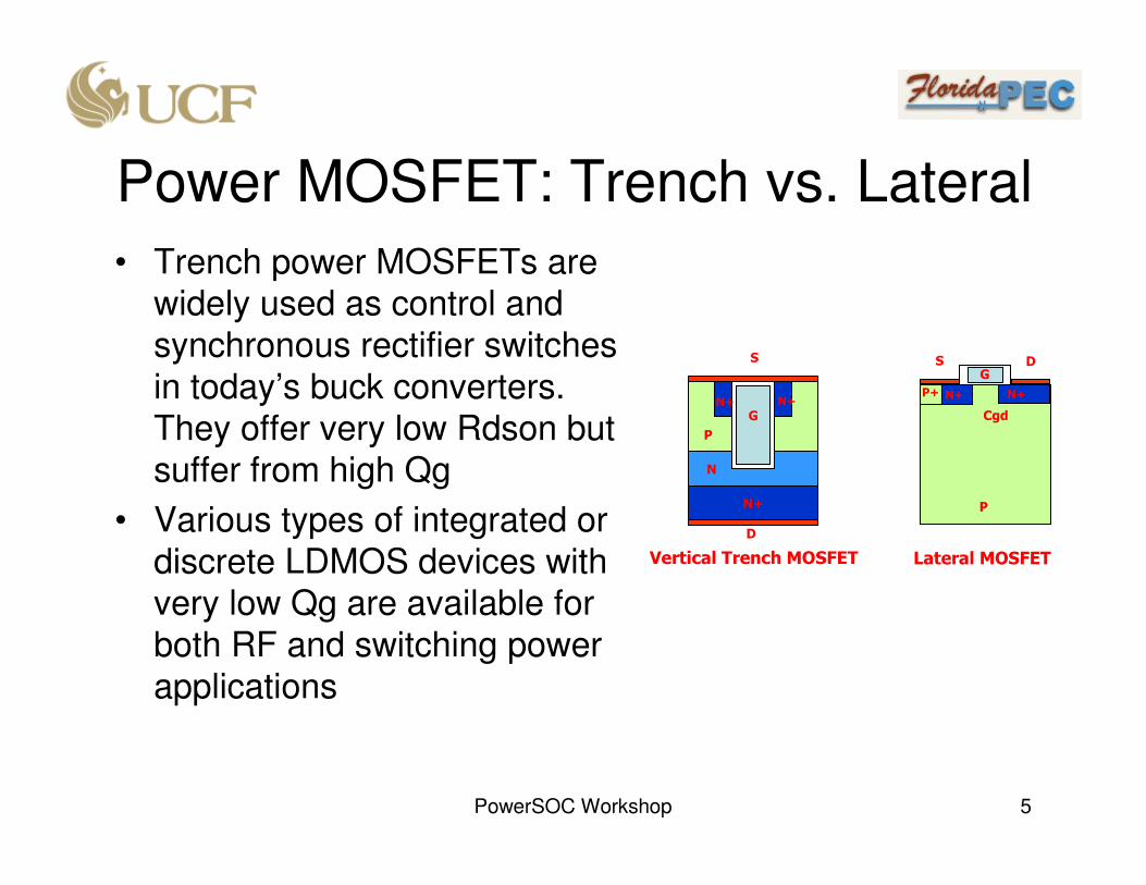
Power MOSFET: Trench vs. Lateral
• Trench power MOSFETs are widely used as control and synchronous rectifier switches in today’s buck converters. They offer very low Rdson but suffer from high Qg
• Various types of integrated or discrete LDMOS devices with very low Qg are available for both RF and switching power applications
N+
N
P
N+
G
S
D
P
S
Cgd
G
N+ N+P+
D
Vertical Trench MOSFET Lateral MOSFET
N+

PowerSOC Workshop 6
Various Trench Power MOSFETs
p-
body
n-epi
p-
body
poly
gate
n
+
n
+
n
+
n
+
p-
body
poly
gate
Base Line Thick Bottom Floating poly plug
Narrow Trench High DensityLow Density
n+
p-
body
n-epi
n+
p-
body
poly
gate
30V trench MOS cell density has increased from 20M to 450M cell/in2 and Rdson has decreased from 30 mΩmm2 to 10 mΩmm2 in the past decade.

PowerSOC Workshop 7
Various Lateral Power MOSFETsS
G
N+ N+P+
D
Basic RESURF LDMOS Structure widely used in power ICs up to over 100V. Benchmark Rdsonfor 30V LDMOS is 20 mΩmm2 P+ substrate
P epi
P-base
N-drift Very low Qg!!!But metal interconnect resistance is a limiting
factor!
S S S S
D D D
S S S S
D D D
S
G
N+ N+
D
P+ substrate
P epi
P-base
N-drift
Great Wall Semiconductor
chip scale LDMOS approach
P+
Bottom-Source LDMOS
(widely used in RF power
amplifier applications)
D
G
N+
S
N+ substrate
P epiP-base
N-driftP+
N-buffer
Bottom-Drain LDMOS
(Ciclon Semiconductor’s
new benchmark device)
N+

PowerSOC Workshop 8
Comparison of 30V Trench and Lateral Power MOSFETs
Ciclon LDMOS(CSD16401Q5)
PowerSOC Workshop 9
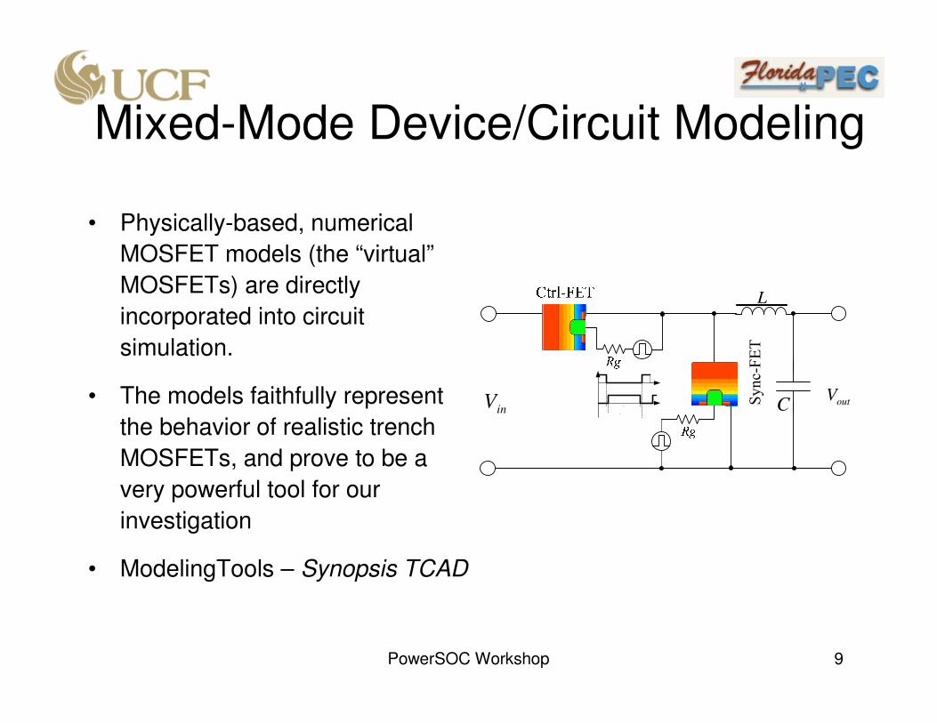
Mixed-Mode Device/Circuit Modeling
Sync-FET
inV outVC
L
2ont
T
• Physically-based, numerical
MOSFET models (the “virtual”
MOSFETs) are directly
incorporated into circuit
simulation.
• The models faithfully represent
the behavior of realistic trench
MOSFETs, and prove to be a
very powerful tool for our
investigation
• ModelingTools – Synopsis TCAD

PowerSOC Workshop 10
Mixed-Mode Device/Circuit Modeling
• 30V “virtual” trench
MOSFET device
structure (4µm cell pitch)
outVC
L
2ont
T
V12Ω05.0
20/1 AV
• Buck converter circuit:
Typical VRM design spec,
Vin=12V, Vout=1V, Iout=20A

PowerSOC Workshop 11
Power MOSFET Characteristics:Modeling vs. Measurement
Gatecharacteristics
Capacitancecharacteristics
Output characteristics
Virtual MOSFETCharacteristics
IRF6617 Measured Characteristics
Ctrl-FET
PowerSOC Workshop 12
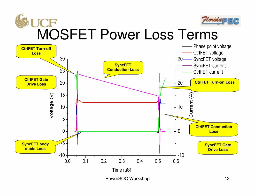
MOSFET Power Loss Terms
SyncFET
Conduction Loss
CtrlFET Turn-off Loss
CtrlFET Turn-on Loss
SyncFET body diode Loss
CtrlFET Gate Drive Loss
SyncFET Gate Drive Loss
CtrlFET Conduction Loss
PowerSOC Workshop 13
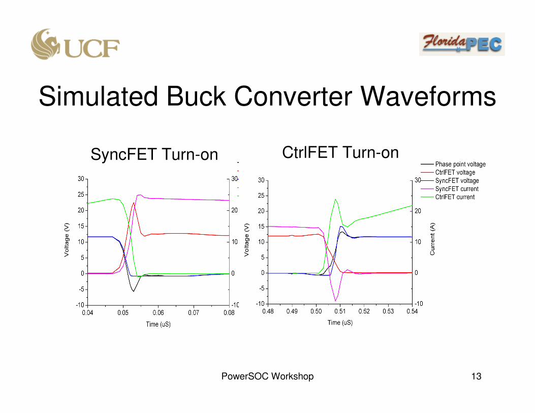
Simulated Buck Converter Waveforms
SyncFET Turn-on CtrlFET Turn-on

PowerSOC Workshop 14
MOSFET Power Loss Contributions
• Turn-on and turn-off
switching losses of
CtrlFET and body
diode loss of
SyncFET dominate
the total power loss
at MHz switching
frequency
• Sync-FET gate drive
loss is also
significant
PowerSOC Workshop 15
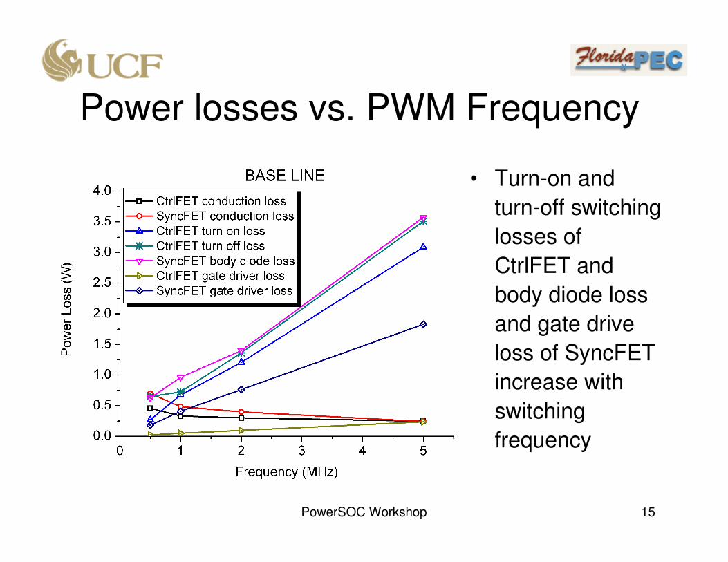
Power losses vs. PWM Frequency
• Turn-on and
turn-off switching
losses of
CtrlFET and
body diode loss
and gate drive
loss of SyncFET
increase with
switching
frequency
PowerSOC Workshop 16
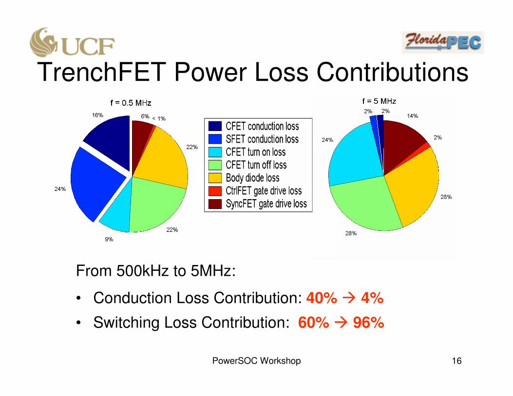
TrenchFET Power Loss Contributions
From 500kHz to 5MHz:
• Conduction Loss Contribution: 40% 4%
• Switching Loss Contribution: 60% 96%

PowerSOC Workshop 17
Comparison of Trench Power MOSFET Technologies
106.22180.85611.319.2457.25724042813189.41.94Low density
45.12128.6394.813.68518.09610512615469.40.622High density
47.94114.685.112.233.097106.923313039.41.106Narrow
trench
42.3109.984.511.736.296118.9227.31410.39.41.138Floating poly
plug
39.4898.7474.210.50528.14109.2212.21230.89.41.04Thick bottom
47127.71785.013.58731.99214423412639.41Base line
Ron*Qgd
(mΩ*nC)
Ron*Qg
(mΩ*nC)
Qgd
(nC)
Qg
(nC)
Qrr
(nC)
Crss
(pF)
Coss
(pF)
Ciss
(pF)
Ron
(mΩ)
Area
FactorType

PowerSOC Workshop 18
Comparison of Trench Power MOSFET Technologies
• The thick bottom
trench MOSFET
technology offers the
highest efficiency in
the MHz frequency
range.

PowerSOC Workshop 19
Comparison of Trench Power MOSFET Technologies
9.4/2.2
9.4/2.2
9.4/2.2
9.4/2.2
9.4/2.2
9.4/2.2
Ron
Ctrl/Sync
(mΩ)
Low Density
High Density
Narrow Trench
Floating Poly Plug
Thick Bottom
Baseline
11.319.2457.257
4.813.68518.096
5.112.233.097
4.511.736.296
4.210.50528.14
5.013.58731.992
Qgd
(nC)
Qg
(nC)
Qrr
(nC)
PowerSOC Workshop 20
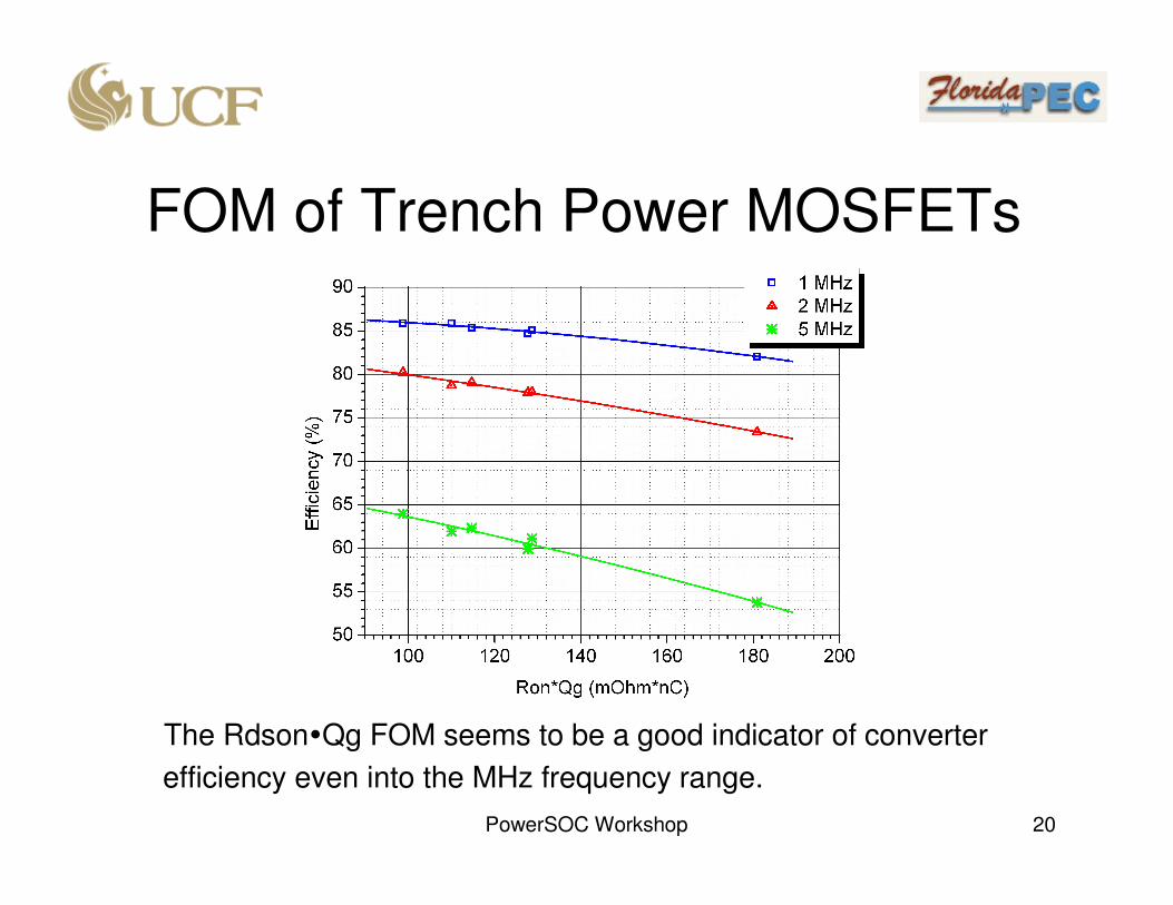
FOM of Trench Power MOSFETs
The RdsonQg FOM seems to be a good indicator of converter
efficiency even into the MHz frequency range.

PowerSOC Workshop 21
Trench vs. Lateral MOSFETs

PowerSOC Workshop 22
Trench vs. Lateral MOSFETs

PowerSOC Workshop 23
Trench vs. Lateral MOSFETs

PowerSOC Workshop 24
Summary• The RDS(ON)×QG Figure of Merit (FOM) still correlate well to buck
converter efficiency in the low MHz frequency range
• LDMOS offers significant efficiency improvement (up to 5 percent
points at 5 MHz) over trench power MOSFETs in buck converters.
The improvement mainly comes from the reduced gate drive power
losses and switching times due to low Qg.
• The efficiency of the hard switching buck topology is limited to 80%
at 2MHz and 65% at 5MHz even with lateral MOSFETs. CtrlFET
switching loss and SyncFET body diode loss predominantly limit the
efficiency of hard switching buck converters using either trench or
lateral MOSFET chipset.
• Soft switching topology and resonant gate drive technology are needed for even higher MHz ranges. A new MOSFET FOM may be needed for those new circuits.