Embed Size (px)
Citation preview
Performance Analysis of FSO Communication Systems
with Higher-Order Spatial Diversity Schemes Using BPSK-
SIM over Log-Normal Atmospheric Turbulence Channels
Okikiade A. Layioye1, Thomas J. O. Afullo
1, and Pius A. Owolawi
2
1 University of KwaZulu-Natal, Durban, 4001, South Africa
2 Tshwane University of Technology, Pretoria, South Africa
Email: [email protected]; [email protected]; [email protected]
Abstract—Free Space Optical (FSO) communication system is
an optical wireless connectivity operating at an unlicensed
optical spectrum, with lots of advantages over the conventional
Radio Frequency (RF) transmission. However, the performance
of the FSO channel is limited due to atmospheric turbulence and
severe weather conditions. There are many authors who have
worked on mitigating these effects by using Spatial Diversity
(SD) with 2X2-MIMO systems and few have worked up to
4X4-MIMO systems, blended with BPSK-Sub-carrier Intensity
Modulation (BPSK-SIM) under the log-normal atmospheric
turbulence model. However, in this paper, we extended the SD
technique to higher-order configurations such as 8X8-MIMO
system in order to improve the performance obtained from
lower-order FSO systems. This study was considered at log-
irradiance variance values of 0.1 and 0.9, representing the
mildly weak and moderately weak atmospheric turbulence
regimes respectively. This work has presented the performance
analysis of various FSO-SD techniques. As a result, at BER of
10-9 the 1X8, 4X4, 6X6 and 8X8 higher-order SD systems were
≈46%, 55%, 61% and 69% respectively better than the "non-
diversity" FSO system during the moderately weak atmospheric
condition. Also, their channel capacities were ≈74%, 77%,
85% and 89% respectively better than the "non-diversity" FSO
system at SNR of 30 dB. Index Terms—Atmospheric turbulence, BPSK-Sub-Carrier
intensity modulation, free space optical communication systems,
higher-order spatial diversity technique, log-normal atmospheric
turbulence model
I. INTRODUCTION
Free Space Optical (FSO) Communication System is
an Optical Wireless Communication (OWC) system that
can be described as a robust technology that provides
users with a superior mobility, flexibility as well as high
data rate. The FSO communication system conveys
information by transmitting laser beams through the
atmosphere to a photodetector. In the recent years, it has
attracted applications in both indoor and outdoor wireless
communications. It has proven to be a good and viable
substitute to other traditional wireless communication
systems due to its large bandwidth, easy deployment and
Manuscript received May 25, 2017; revised July 13, 2017.
Corresponding author email: [email protected]. doi:10.12720/jcm.12.7.379-394
commissioning, and cost effectiveness. The sophisticated
outdoor wireless capabilities of the FSO system, with lots
of other optimal services mentioned above are part of its
advantages over other types of wireless communication
systems. Based on its numerous and broad applications,
the FSO communication system has attracted great
attention and has become a widely used OWC system for
the improvement of the Average Channel Capacity (ACC)
of communication systems [1]-[5].
The motivation for alternative technology that meets
today’s wireless access platform is as a result of the last-
mile bottleneck. This is coupled with continually
increasing demand placed on the need for higher
bandwidth and transmission rate, along with certain
Radio Frequency (RF) limitations due to frequency
spectrum congestion [1], [6], [7]. The FSO system has
proved to be a communication system with allocation for
high speed, broad (wide) bandwidth, interference-free,
highly directional, reasonable security, license-free,
robust communication services with less time of
deployment and also importantly it has a low
maintenance cost. Another advantage of the FSO is its
ability to equal the speed of the Fiber optics, which is as
high as 1.25 Gbps and as a matter of fact, it has the ability
to surpass this speed to reach 10 Gbps. The reason being
that it transmits data faster through air than in the glass
fibers used in fiber optics [1], [8], [9].
However, the effects of the atmospheric conditions
greatly determine the reliability and efficiency of the FSO
communication system by causing a fluctuation in the
irradiance of the optical signal which is known as
atmospheric scintillation [10]-[12]. The main
disadvantages of the FSO communication system arise
from the occurrences associated with atmospheric
conditions resulting into atmospheric turbulence or
adverse weather conditions. The atmospheric turbulence
effects are caused by the differences detected in the
refractive index as a result of the in-homogeneities in
temperature and also by fluctuations obtained in air
pressure along the transmission pathway of the laser
beam [4], [12], [13]. The effects of the index in-
homogeneities obviously have a great deteriorating
impact on the quality of the received signal and at the
same time it can cause variations in both the received
379
Journal of Communications Vol. 12, No. 7, July 2017
©2017 Journal of Communications

signals’ intensity and phase. As a matter of fact, the long
run effects of these variations can result into an
increasing link error probability, thereby causing a
limitation to the performance of the FSO communication
system. These atmospheric turbulence conditions can be
categorized into weak, intermediate and strong
atmospheric turbulence regimes depending on the level of
the atmospheric turbulence strength [4], [5], [12], [14].
The Received Optical Signal Level (ROSL) at the
receiver can be adversely affected as a result of
atmospheric disorders such as the occurrence of Fog and
haze which leads to beam scattering, thereby reducing the
ROSL. Also, the higher the magnitude of the fog, the
higher the attenuation that it produces. Attenuation
exceeding 300 dB/km is caused by heavy fog, which in
turn limits the length of the FSO link to a range that is
less than 100m [6], [15], [16]. The effects of some
atmospheric conditions such as rain and snow are not
quite harmful to FSO communication systems, but it has
been observed that they mainly cause serious attenuation
to the radio and microwave frequencies [6], [16], [17].
Overcoming the corruption effects on optical signals
caused by fading that has been induced by turbulence can
be achieved by several diversity techniques. The
employment of different methods under the diversity
techniques can be used to improve the channel
performance of the FSO communication links. The
conventional diversity techniques used in FSO
communication system are space diversity, time diversity,
wavelength diversity, frequency diversity and temporal
diversity [18]-[20]. As sited by several authors, spatial
diversity technique can be considered as a promising
mitigating technique for FSO communication to produce
a high data rate. This led to an investigation into the
spatial correlation amongst a pair of configured
transmitters in a Multiple Input Multiple Output (MIMO)
structure as presented in [21]. However, the atmospheric
effects are controllable and can be greatly minimized to a
reasonable level through the use of the MIMO technique.
This includes the application of multiple lasers at the
transmitter end as well as multiple photodetectors at the
receiver end [18], [22], [23]. Another work discussed the
performance investigation of multi-beam Free Space
Optical system using diversity techniques [24].
The choice of the appropriate modulation scheme to
achieve an optimum FSO performance is a key factor in
mitigating against the induced fading which is as a result
of atmospheric turbulence. The modulation techniques
that are the simplest as well as most extensively
employed for FSO systems are the On-Off Keying (OOK)
scheme and the Pulse Position Modulation (PPM) [6], [9],
[13]. Though the OOK scheme has shown that it doesn’t
deliver any form of protection or resistance to induced
fading caused by the atmospheric turbulence [4], [6], [14],
[25]. The level of the optical intensity obtained at the
position of the receiver sometimes experiences a random
instability which is caused by the non-predictive behavior
of the atmospheric turbulence level. Therefore, all these
suggest that for the OOK technique to produce an
optimum performance when it is applied, it will definitely
need an adaptive thresholding scheme. However, due to
the formation of this scheme, the implementation tends to
be complex and practically not suitable [6], [17], [26].
Meanwhile, the PPM modulation technique on the other
hand seems to have a poor bandwidth efficiency, despite
its low cost and simplicity [13]. Applying the modulation
schemes that convey the required information in either
the frequency or the phase of the carrier signal has
become a reasonable and better approach. This is because
the level of the optical intensity in FSO communication
system is drastically affected by fog and scintillation [6].
Therefore, following the trend of current researches, a
proposition has been made that the limitations obtained
from the employment of the OOK or PPM can be
overcome by the employment of Sub-carrier (SC)
Intensity Modulation (SIM) schemes. The various types
of Sub-carrier Intensity Modulation schemes that can be
applied are: Sub-carrier Binary Phase Shift Keying (SC-
BPSK) and Sub-carrier Quadrature Amplitude
Modulation (SC-QAM). However, this paper employed
the former. As a matter of fact, the Binary Phase Shift
Keying (BPSK) based SIM does not need any adaptive
thresholding scheme and it is moderately bandwidth
efficient. This makes it a better option when compared to
the operations of the OOK and PPM in the presence of
fading channels that have been induced by the
atmospheric turbulence [14], [20], [27], [28]. Thus, a
comprehensive investigation of the FSO communication
system performance using SC-PSK has been shown in
[17], [25], [28], [29], but without considering the spatial
diversity technique. Wilson et al. in [30]-[32], considered
the FSO MIMO communication system using the Pulse
Position Modulation (PPM) and the Q-ary PPM under
two turbulent induced fading channels which are: the log-
normal and Rayleigh fading channels, and then made
expressions and analysis on the Bit Error Probability
(BER) and the Symbol Error Probability (SER).
Apart from the usual study of Average Bit Error Rate
(ABER) and Average Symbol Error Rate (ASER)
performance for MIMO-FSO communication systems,
the average capacity performance of these systems are
now recently studied in [13], [33]. The Average Channel
Capacity (ACC) is also a standard metric system for
determining the maximum possible data rate (in b/s/Hz)
consistently transmitted between the transmit lasers and
the receive photodetectors in the FSO communication
regime [34]. In addition to the BER and the ACC
performance analysis studied in this paper for higher-
order spatial diversity FSO systems, the Outage Channel
Capacities (OCC) of these FSO systems were also studied
under the weak turbulence regime.
Thus, from the foregoing, the performance on the ACC
of FSO-MIMO Communication systems under different
atmospheric turbulence induced fading channels such as
the weak, intermediate and strong atmospheric turbulence
fading channels has not been fully investigated. This
380
Journal of Communications Vol. 12, No. 7, July 2017
©2017 Journal of Communications

work investigates the BPSK-SIM over MIMO and other
Spatial Diversity (SD) techniques (such as Single Input
Multiple Output (SIMO) and Multiple Input Single
Output (MISO)); whereby the Subcarrier Intensity
Modulation is employed to improve the capacity of the
FSO system by making sure that the multiple sources are
being modulated at different sub-carriers. Though, to
obtain a preferred BER performance, the penalty that is
paid is the higher SNR. Therefore, in situations whereby
we place great priority on the increase in capacity of the
system more than the power requirement, then it will be
proper to choose the multiple SIM technique.
The arrangement of this paper is given as follows:
Section 2 explains explicitly the system and channel
models that were used in this work. The performance
analysis showing the BER, ACC and OCC of the various
higher-order spatial diversity schemes are presented in
Section 3. Numerical results as well as the graphical
analysis of the higher-order spatial diversity schemes
under the mildly weak and moderately weak atmospheric
turbulence regimes are shown in Section 4. Finally, the
last section states the conclusion with remarks of this
paper.
II. SYSTEM AND CHANNEL MODELS
A. System Model
1) FSO-SISO systems using BPSK
The whole system model in this case involves the Free
Space Optical SISO system using BPSK modulation
technique with a structure that consists of a single
transmitter at the input and a single receiver at the output
of the optical link. This type of FSO system employs
BPSK signaling to modulate the intensity of the optical
signal produced by the single transmit laser by means of a
carrier signal created by the modulator.
A simple block diagram to describe the Free Space
Optical SISO system which uses the BPSK-SIM
modulation technique is shown in Fig. 1. The source
input data (di) which carries the information to be
conveyed to a user at a distant destination, becomes
modulated by the BPSK modulator onto the created RF
subcarrier. It is then relayed onto a laser which is
described as an optical carrier. The g(t) in the FSO SISO
BPSK-SIM block diagram denotes the rectangular pulse
shaping function of the BPSK modulator. In order to bias
the optical carrier appropriately, the created complex RF
signal is being mixed with a DC bias signal bo. This
synchronization ensures that the optical carrier totally
accepts the full swing of the time varying RF subcarrier
signal. Thus, after synchronization with the DC bias
signal, the intensity of the optical source becomes
modulated by the RF subcarrier. However, the modulated
optical information produced by the laser is transmitted
over the free space which is an atmospheric channel. The
atmospheric channel considered in this paper is a weak
turbulent regime. The log-normal distribution is used to
model the weak turbulence effect which results into
fading of the transferred optical signal intensity. Using a
Coherent Detection (CD) technique at the receiver, we
can conveniently recover the complex Sub-carrier
Intensity Modulated signal that has been superimposed on
the covering of the inbound optical signal. In order to
capture the sub-carriers, the Electrical Bandpass filters
are used. Following this is the standard RF coherent
detector which is also the BPSK demodulator that, thus
recovers the transferred data series given as Di.
Fig. 1. The block diagram of BPSK sub-carrier intensity modulated SISO-FSO link under the log-normal atmospheric channel.
In this SISO case, a single RF sub-carrier that has
BPSK sub-carrier amplitude, sub-carrier phase and sub-
carrier frequency as Ac, ac, and fc is being used [6]. It is
confirmed that as the photodetector (PD) optically detects
381
Journal of Communications Vol. 12, No. 7, July 2017
©2017 Journal of Communications
and collects optical signal at the receiver end, this process
is done in the presence of the following: signal distortion,
noise interference and background radiation [8]. The
expression for the transmitted optical signal intensity
from the single laser driver is expressed as [14]:
ba ePts 1)( (1)
where Pa represents the average optical signal power per
bit and κ denotes the index of modulation which is given
as 10 . However, the Peak transmitted optical
signal power (Pp) is related to the average optical signal
power per bit as follows: 2/pa PP .
The electrical BPSK sub-carrier signal )]([ teb is
given as [6], [25]:
)2cos()()( cccb atftgAte (2)
where t is the time in seconds and all other parameters
remain as earlier described. Thus, (1) becomes:
)]2cos([12
)( ccc
patfA
Pts (3)
After modulation, the transmitted optical signal from
the laser is transmitted over the atmospheric turbulence
regime where it gets distorted by atmospheric effects,
such as scintillation, fog, rain, snow and so on. Thus, in
an FSO communication system with the effects of
scintillation and the likes, the received optical signal
intensity r(t) at the input of the single photodetector is
given as [35]:
)()()( tPtaCtr o (4)
In (4), parameter a denotes the atmospheric attenuation
factor contributed by other effects rather than scintillation,
C(t) is the signal scintillation factor due to the effects of
the atmospheric turbulence, which can then be
demonstrated as a stationary random process. Po(t)
represents the received signal intensity without
considering the effects of scintillation. However, it can be
said that s(t) = Po(t).
Therefore, for BPSK systems in an FSO
communication system, the received optical signal
intensity at the input of the single photodetector is given
as [14]:
)()()( tstaCtr (5)
)]2cos([12
)()( ccc
patfA
PtaCtr (6)
This received optical signal intensity has already been
distorted while being transmitted over the atmospheric
turbulence channel. Consequently, since we are
considering the weak atmospheric turbulence channel in
this paper, C(t) can be modelled with the Log-normal
distribution as a stationary random process.
The mean amplitude )2
)((pP
taC of the received
electrical signal which is also called the DC term of the
signal can be filtered out using a bandpass filter, which is
incorporated into the receiving end of the FSO system.
Hence, at the output of the photodetector, after it has been
filtered and converted from the optical form, we can
obtain the expression for the electrical signal as follows
[14].
)()(2
)()( tteP
taCtr b
p
e
)()2cos(2
)()( tatfAP
taCtr ccc
p
e (8)
where is the Photodetector’s responsivity; this is a
parameter that gives the responsivity of the photodetector
or how reactive the photodetector is. )(t represents the
total receiver noise. This noise factor contributed or
accumulated at the receiver can be modelled as an
Additive White Gaussian Noise (AWGN) process which
has a power spectral density 0N .
Finally, the received electrical signal undergoes BPSK
demodulation and then afterwards becomes sampled in
order to recover the original information (data). Hence,
for the BPSK demodulation of the received electrical
signal )(tre , the output signal )(tR that contains the
original data can be finally obtained after the received
electrical signal )(tre is demodulated by the reference
signal )2cos( tfA cc and given as [14]:
)2cos()()( tfAtrtR cce (9)
)(22
)()( tAP
taCtR cp (10)
Therefore, after the BPSK-SIM coherent detection
demodulation, baseband electrical signal that will be
obtained at the end of the FSO SISO communication link
is given as [14], [35]:
)()(4
1)( tAPtaCtR cp (11)
2) FSO spatial diversity systems using BPSK
The Spatial Diversity technique involves employing
multiple antennas on either the transmitter or receiver
(MISO or SIMO respectively), or having more than one
antenna on both the transmitter and receiver as in the case
of MIMO. However, as shown in Fig. 2, a universal
RT NM FSO Diversity system using the BPSK-SIM
modulation technique can be considered and deduced.
Hence, this generic formulation can be used to handle the
FSO-MISO, FSO-SIMO and FSO-MIMO systems.
382
Journal of Communications Vol. 12, No. 7, July 2017
©2017 Journal of Communications
(7)

Fig. 2. The block diagram of BPSK sub-carrier intensity modulated spatial diversity FSO links under the log-normal atmospheric channel
In this paper, the systems described above employed
BPSK signaling with a set of TM transmitting lasers
directed towards a set of aligned RN receiving
Photodetectors (PD). The TM transmitting lasers
individually provide an explicit perfect synchronized data
transmission which employs similar BPSK signals. These
data transmission, with seamless synchronization by each
of the transmitting lasers, provide a stream of data
transmitted through an atmospheric turbulence channel
directed towards the RN photodetectors at the receiving
end. However, in order to justify the performance
analysis, it is important to make certain assumptions such
as assuming that each transmit telescope’s light beam-
width is sufficiently broad to make sure that the receiver
array is being completely illuminated. Also, it is essential
to include the assumption that irrespective of TM , the
same total optical power is being produced by the
transmitter’s telescope array. This is done in order to
impose a reasonable evaluation with the case of a system
having a single transmit telescope. The spatial correlation
has to be insignificant when considering these spatial
diversity techniques. Thus, for this to be negligible, it has
to be assumed that the distance between the discrete
transmit and receive telescopes is sufficient.
The model for the turbulence channels of the various
Diversity systems can be represented by an atmospheric
turbulence channel C , having an RT NM matrix
which describes the configurations of the Diversity
turbulence channel, and it is given as [13], [14]:
RT NM
nmmn tCC,
1,)]([ (12)
However, at the input of the BPSK demodulator, the
electrical signal is given as [13], [14]:
)()()](][][][2
][[)(1 1
ttCteP
atrT RM
m
N
n
mnb
p
e
(13)
m = 1, 2 …, MT and n = 1, 2 …, NR,
where )(tCmn represents the stationary random process
which describes the atmospheric turbulence channel
between the mth transmit laser to the nth photodetector,
and )(t denotes the Additive White Gaussian Noise
with zero mean and a noise power )(
0
nN .
The transmitted electrical signal can be estimated at
the receiving end by employing the means of a Maximum
Ratio Combining (MRC) Detector. The MRC was chosen
in this paper due to the fact that in terms of optimum
performance, it has a combining gain advantage which
adds benefits to the FSO system. This is as a result of the
fact that the required SNR expected to reach a certain
BER performance is slightly lower for MRC compared to
other combining schemes such as Equal Gain Combining
(EGC) and Selection Combining (SC). Unlike other
combiners, the MRC performs its operation by estimating
the gains of all the channels of the diversity system.
Therefore, as a result of this, a finite sum of the
individual sub-channel Signal to Noise Ratios can be
obtained. This respectively gives an expression for the
Instantaneous Electrical SNR (IE-SNR), and it is given as
follows [13], [14]:
2
1 1
)(
T RM
m
N
n
mn (14)
2
1 1
)(
T RM
m
mn
N
n
mn C (15)
383
Journal of Communications Vol. 12, No. 7, July 2017
©2017 Journal of Communications

The factor mn is obtained as Random Variables (RVs)
of arbitrary sizes and it describes the component of the
Instantaneous Electrical SNR. This component is caused
by the signal that results from the sub-channel. Each of
the sub-channels that exist from the mth transmit laser
to the nth photodetector contributes to the Instantaneous
Electrical SNR (IE-SNR). Thus, mn is expressed as
follows [13], [14]:
mnmn
amn
RTmn C
N
PaCNM 2
0
2)1
(
(16)
where 0N is a representation of the total noise power of
the system. However, from a combination of the various
instantaneous electrical SNR components obtained from
the various sub-channels in the middle of the mth
transmit laser and the nth photodetector, the average
electrical SNR )( mn can be found and it is contributed
by the various sub-channels. From (16), mn is obtained
as [13], [14]:
0
2)1
(
N
PaNM
a
RT
(17)
Hence, for FSO SISO communication system, the
average electrical signal to noise ratio is given as:
0
2)(
N
Pa a
(18)
(since m = n = 1, for SISO systems).
B. Channel Model
1) Atmospheric turbulence model
The irradiance fluctuations that arise in the FSO
system as a result of certain atmospheric turbulence
conditions within the link regime can be described using
various statistical models. However, the irradiance
fluctuations can be described in various levels based on
the impact of the atmospheric turbulence. This has led to
the fact that the atmospheric turbulence condition can be
categorized as weak, intermediate (moderate) or strong
turbulent conditions.
The atmospheric turbulence induced fading that
describes perfectly the weak atmospheric turbulence
condition used in this paper is expected to be a random
process that has the same pattern like the log-normal
distribution [13], [17]. On the other hand, the random
process for the atmospheric turbulence induced fading for
the intermediate and the strong turbulence conditions
follows the Gamma-Gamma distribution [13], [20].
2) The log-normal turbulence model
The Random process of the turbulence induced fading
as a result of the influence of the weak atmospheric
turbulence condition, can be modelled using the log-
normal distribution function. This Log-normal turbulence
model offers an opportunity to describe the weak
atmospheric turbulence induced fading channel during
the propagation of signal from the transmitter to the
photodetector.
The Probability Density Function (PDF) that
mathematically expresses the log-normal fading channel
for an irradiance with log-normal Random Variable (RV),
when 0mnC , is given as follows [5], [14], [35]:
)2
)2
)(ln(
exp()2(
1)(
2
22
I
Imn
Imn
mnmn
C
CCf
(19)
where m = 1, 2 …, MT and n = 1, 2 …, NR.
The variance parameter of the distribution used in this
case is called the Rytov Variance which is denoted by the
parameter 2
I , and it is expressed as follows [6]:
)6/11()6/7(22 23.1 LkCnI (20)
Under the weak scintillation theory, this Rytov
Variance expression in (20) is mostly used when we
assume a plane wave propagation. However, it can be
said that the Rytov variance is proportional to the
scintillation index. In the expression above showing the
Rytov variance, the atmospheric turbulence strength or
the refractive index parameter is represented using 2
nC .
This parameter depends on the altitude of the optical link,
and according to the atmospheric turbulence condition, it
has a range that varies from 1710
to 1310
3/2m [13],
[14].
The expression for the normalized Log-irradiance
variance also called the scintillation index )( 2
s is given
as [13], [14]:
1)exp( 21
2 s (21)
where parameters 1 and 2 respectively are given as
[13]:
6/75/122
2
1)56.018.01(
)49.0(
I
I
d
(22)
6/55/122
2
1)62.09.01(
)51.0(
I
I
d
(23)
From the above expressions, we have the following
parameters: the optical parameter, d , which is given as:
LkD 4/)( 2 , and also, the optical wave number, k , is
given as: /2 . Where D represents the receiver
aperture diameter of the Photodetector, the optical Link
distance in meters is represented by L , and the optical
wavelength in meters is denoted by .
384
Journal of Communications Vol. 12, No. 7, July 2017
©2017 Journal of Communications

III. PERFORMANCE ANALYSIS
A. Bit Error Rate Analysis for Log-normal Channel
Model Using BPSK-SIM
Considering the same transmitted data symbols, that is,
when the system allows the transmission of a data symbol
‘1’, the Bit Error Rate (BER) can be derived as the
probability of the output signal after demodulation to be
less than zero )0)(( tR . Therefore, it can be said that
the theoretical unconditional BER per subcarrier channel
is given as [14], [35]:
0
)( )()( dCCfCPP ciee (24)
where )()( CP ie represents the instantaneous probability
of error that is the same as the probability of obtaining
0)( tR , whereby )(tR is considered as a Gaussian
random process that has an instantaneous mean given as
cp APtC )(4
1 and a noise variance of 2
N . The
parameter )(Cfc represents the PDF of the random
process which is as a result of the atmospheric
scintillation within the system. Thus, the instantaneous
error probability is given as [35]:
0
2
2
)( ]2
)4
)((
exp[2
1dR
ACPtR
PN
cp
N
ie
(25)
)4
( CAP
QN
cp
(26)
Q (27)
where (.)Q denotes the Gaussian Q-function and it is
given as [35]:
y
dttyQ )2exp(2
1)( 2
(28)
and the noise variance 2
N at the input of the BPSK
modulator is given as [35]:
fFR
TkfCPFqG N
L
BpAN )4()4
(2 22 (29)
Also, 2
0 2 NN , such that 0N represents the Noise
Power Spectral Density (PSD) and where
BNA kFfTFGq ,,,,,, and LR all represent the
charge of the electron, average Avalanche Photo-Detector
(APD) gain, additional noise factor, receiver noise
temperature, effective noise bandwidth, noise figure of
the amplifier, Boltzmann’s constant and load resistance
respectively.
During the weak atmospheric turbulence event in an
FSO communication system, it is already a fact that the
log-normal distribution perfectly describes the primary
influence of turbulence ))(( tC which is identified as a
random process [35]. The PDF ))(( Cfc for an FSO
system described by a log-normal distribution can be
expressed using the expression given in (19). The
variance parameter 2
I in this expression also represents
the log-irradiance variance, which determines the strength
of the atmospheric turbulence condition and it is a value
that is dependent on the characteristics of the channel.
This log-normal PDF continues to be valid for the
Scintillation Index (S.I) which is given as [35]:
1.2
2 IeIS s
. (30)
Thus, using Eq. 30, the scintillation indices chosen for
this research work were obtained from the selected log-
irradiance variance values. These scintillation indices
values are within the range of values that the log-normal
model can handle. Therefore, we used these set of values
to determine the minimum and maximum effects of weak
atmospheric turbulence on the channels of the FSO
communication links. Since the limit of the log-irradiance
variance values that the log-normal model can handle for
the weak atmospheric turbulence regime is 1.2 [6], thus,
in this paper we chose to limit ourselves to log-irradiance
variance values from 0.1 to 0.9.
The BER expression for the FSO system can be
obtained by substituting (19) and (26) into (24), and this
is shown below:
0
)4
( CAP
QPN
cp
e
dCC
C I
I
I
]2
)2/)(ln(exp[
2
12
22
(31)
B. Average (Ergodic) Channel Capacity Analysis
1) Average Spectral Efficiency (ASE)
The Average Channel Capacity (ACC) is a very
essential metric which can be used to determine or
evaluate the optimal performance of the optical link. It
can as well be used to determine the data rate that
communicates between the available M-transmitter and
N-photodetector. However, if the channel frequency
response is known, and since the ACC is a system for
obtaining the maximum achievable data rate, then we can
also conveniently express the ACC of the systems in
terms of the Average Spectral Efficiency (ASE) which
will then be given in bits/seconds/Hertz [13], [14].
In the presence of weak atmospheric turbulences with
fading strength less than one, the ACC can be derived
analytically as shown in this section, for both the SISO-
FSO link and the spatial diversity-FSO links including
the RT NM MIMO-FSO link.
385
Journal of Communications Vol. 12, No. 7, July 2017
©2017 Journal of Communications

The following assumptions were taken into
consideration for this work in order to determine the ASE
of the system:
(a). The optical channel of the FSO communication
system is presumed to be tractable, stationary, ergodic
with independent and identically distributed (i.i.d.)
turbulence statistics and memoryless.
(b). A seamless (perfect) Channel State Information
(CSI) is present at the M-transmitting optical lasers as
well as at the N-receiving apertures [14].
Therefore, the ASE of the system can be expressed as
follows [13], [14]:
dfHzsbitsB
CC R
c )()1(log)//( 2 (32)
where RC is the channel’s bit rate, B is the
transmission bandwidth of the ergodic optical channel,
denotes the total Signal to Noise Ratio (SNR) of the
optical channels, )(f represents the joint Probability
Density Function for the available array of optical
channels present in the atmospheric turbulent regime and
then the parameter is a matrix representation of the
MIMO atmospheric turbulence induced optical channels,
and it is given as follows [5]:
Tmn Mm ,,1,{ },,1 RNn (33)
The expression in (32) above which can likewise be
referred to as the ACC of the system is also defined as the
ratio of the channel’s bit rate )( RC to the channel’s
bandwidth )(B .
Since we have assumed that the channel is ergodic,
therefore we can find the ergodic channel capacity for
SISO, MISO, SIMO and MIMO as presented in the next
sub-sections.
2) Ergodic channel capacity of MIMO-FSO channels
According to the arrangement of a MIMO system with
multiple transmit TM and receive RN antennas, the
channel will be represented by a matrix C which is
given as C RT NM . However, the transmitted and
received signals can both be represented as vectors given
as [36], [37]:
(34)
The symbol vector )(x for the transmitted signal
consists of TM unrelated input symbol vectors:
TMxxx ,,, 21 . The received signal )(y can be
expressed in matrix system as [36], [37]:
n
T
x CxM
Ey (35)
where xE denotes the energy of the transmitted optical
signal and n is the noise vector and it is given as:
1),,,(
21
R
RN
NT
nnnn C .
However, the capacity of a channel can be generally
defined as follows [36], [37]:
):(max
)( yxIC xfc bits/channel use (36)
where )(xf is presented as the PDF of the transmitted
optical signal vector )(x in consideration and the mutual
information for both the transmit and received signal is
represented with ):( yxI . Therefore, the capacity of a
channel can be defined as the maximum mutual
information obtained as a result of frequently changing
the PDF of the transmitted optical signal vector.
Using the principle of information theory, the mutual
information is given as [36]:
HzbpsCCINM
EIyxI H
M
T
x
N TR/)det(log):(
0
2 (37)
where the Hermitian symmetric matrix HCC represents
the channel matrix obtained from the auto-correlation
matrix of the received signal y. RNI and
TMI
respectively represent the information about the receive
and transmit antennas.
From (36) and (37), the channel capacity of a MIMO
channel in cases where a deterministic MIMO channel is
assumed, is given in bps/Hz as [36], [37]:
)det(log0
2
max H
M
T
xNMc CCI
NM
EIC
TRTMIMO (38)
In cases where a random MIMO channel is assumed,
thus, the channel matrix C is considered as a random
matrix. Therefore, this suggest that the capacity of the
MIMO channel is also obtained as randomly time-varying.
As a result of this, the capacity of the MIMO channel can
best be described using the time average. Since it is
known that an ergodic process practically describes a
random channel, then the ergodic channel capacity of a
random MIMO channel is given in terms of expected
value as [36], [37]:
)det(log0
2
max H
M
T
x
NM
cc
CCINM
EIE
CEC
TRT
MIMOMIMO
(39)
Thus, when CSI is available at the transmitter end, the
ergodic channel capacity expression for the MIMO
system is presented as shown in (39). However, when
CSI is not available at the transmitter end, then the
expression is simplified into the following [36], [37]:
386
Journal of Communications Vol. 12, No. 7, July 2017
©2017 Journal of Communications

)(log0
2
max H
T
x
NMc CCNM
EIEC
RTMIMO (40)
Meanwhile,
2
1 1
2)(
T RM
i
N
j
ij
H
FcCCTrC (41)
The FSO channel’s total power gain is given as the
squared Frobenius norm of the FSO-MIMO channel [36].
3) Ergodic channel capacity of SISO-FSO channels
For a SISO-FSO system that consists of a single
transmit antenna TM and a single receive antenna RN ,
the received signal )(y can be written in linear form in
terms of the transmitted signal x as:
n
T
x CxM
Ey (42)
where 1TM and C represents the single FSO
channel.
Thus, similarly to (38), the deterministic SISO channel
capacity can be expressed as:
)det(log0
2
max H
M
T
x
NMc CCINM
EIC
TRTSISO (43)
In cases where maximum number of channel =1,
1TMI and 1
RNI , therefore, the ergodic channel
capacity with Channel State Information (CSI) at the
transmitter becomes [36]:
)1(log2
0
2 FT
x
cc CNM
EECEC
SISOSISO (44)
Since 1 RT NM , and where the channel’s total
power gain RTFNMC
2, then the ergodic
channel capacity for a SISO channel in (44) becomes [36]:
HzbpsN
EEC x
cSISO/)1(log
0
2
(45)
Therefore, regardless of CSI available either at the
transmitter and/or receiver sides, the channel capacity for
SISO remains the same.
4) Ergodic channel capacity of SIMO-FSO and
MISO-FSO channels
The SIMO channel to be described has a single TM
transmit antenna along with multiple RN receive
antennas. Since the channel gain can be expressed as
C1RN
, then the time average of the channel
capacity for SIMO system (regardless of CSI availability
at the transmitter) is given in terms of the expected value
as [36]:
)1(log2
0
2 F
x
cc CN
EECEC
SIMOSIMO (46)
where the channel’s total power gain RFNC
2, then
the ergodic SIMO channel capacity expression becomes:
HzbpsNN
EEC R
xcSIMO
/)1(log0
2
(47)
However, for the ergodic MISO channel capacity, we
have the following when CSI is not available at the
transmitter, and when the channel gain is given as
C TM1 [36]:
)1(log2
0
2 FT
x
cc CNM
EECEC
MISOMISO(48)
where TFMC
2, then the expression becomes:
HzbpsN
EEC x
cMISO/)1(log
0
2
(49)
Hence, it can be noticed that the ergodic channel
capacity is the same for the SISO and MISO channels, if
no CSI is available at the transmitter side.
Finally, if the transmitter side of the MISO channel has
the CSI, then the expression becomes [36]:
HzbpsMN
EEC T
xcMISO
/)1(log0
2
(50)
C. Outage Channel Capacity Analysis
The Outage Channel Capacity (OCC), , is an
alternative statistical concept of the channel capacity
which is defined in terms of the outage probability of the
FSO systems. Therefore, to evaluate the OCC in terms of
the rate of transmission )//( HzsbR , we can use the
following outage probability expression [36]:
RCCPRP Cout )(()( )/ Hzbps (51)
whereby for the FSO MIMO channels we can say that
MIMOCC CCC )( . Therefore, (51) becomes:
)(log()(0
2
max RCCNM
EIPRP H
T
x
NMout RT
(52)
In order words, the OCC can be defined as the
maximum attainable data rate obtained when the outage
probability as defined in (51) is less than the outage
387
Journal of Communications Vol. 12, No. 7, July 2017
©2017 Journal of Communications

388
Journal of Communications Vol. 12, No. 7, July 2017
©2017 Journal of Communications
channel capacity. It is required that the decoding error
probability be made arbitrarily small in accordance with
the rate of transmission R . However, in cases where this
is not so, this suggests that the FSO system may
experience an outage. Thus, the ergodic channel capacity
of the spatial diversity FSO systems when there is no
Channel State Information (CSI) at the transmitter end, is
given in terms of the Cumulative Distribution Function
(CDF).
IV. PERFORMANCE RESULTS AND DISCUSSION
In this section, as discussed earlier, the two various
cases of weak atmospheric turbulence (i.e. mildly weak
and moderately weak) analyzed in this paper are
modelled using the Log-normal distribution model with
BPSK signaling to provide a better performance. The
analytical results obtained from the expressions derived
in section 3 are used to make comparative studies on the
performance analysis of the SISO and spatial diversity
FSO systems in Log-normal fading. The analysis shows
the evaluation of the BER, ACC and OCC for various
atmospheric turbulence conditions of turbulence strength:
1.02 I and 9.02 I for respective cases of mildly
weak and moderately weak atmospheric turbulence
regimes. Here, the diameter of the Photo-detector’s
receiver aperture was taken to be 10 cm, the optical
wavelength 850 nm, responsivity of the photo-
detector 1 and for the range of the atmospheric
turbulence links we chose distances of 2 km, 4 km and 6
km.
A. BER Performance Results
Table I shows the input parameters used for obtaining
the BER for the FSO systems considered. The predicted
and calculated BER performance as derived in (31)
against the Signal to Noise ratio in dB for SISO (“non-
diversity”) and spatial diversity schemes employing the
BPSK-SIM through the weak atmospheric turbulence
induced channels is illustrated in Fig. 3. The log-
irradiance variance values of 1.0{2 I and }9.0 were
considered for the log-normal fading channels and also an
ideal channel (with no atmospheric turbulence) was used
as a benchmark for the performance analysis.
TABLE I: INPUT PARAMETERS
Parameter Value
Operating Wavelength 850 nm
Rytov Variance Values at 0.1 and 0.9
Photodetector Responsivity 1
Refractive Index 3/216109 m
Irradiance 0.01 to 5 (500 samples)
Modulation Index 1
Subcarrier Signal Amplitude 1
To achieve a better system performance, we need to
achieve Bit Error probability with values as low as the
order of 910 or less. Fig. 3 shows the BER performance
of various FSO spatial diversity channels from the less
complex ones (such as 21 and 22 systems) up to
very high-order MIMO systems (such as 44 , 66 and
88 MIMO systems) as a function of the SNR, for two
various values of atmospheric turbulence strength (i.e.
1.02 I and 9.02 I ) representing the mildly weak
and moderately weak atmospheric turbulence regimes
respectively. The performance of the “non-diversity”
FSO system (SISO) is also included in the analysis shown
in Fig. 3 for the purpose of comparison and as a
benchmark to measure the diversity gain of the BER or
SNR. The performance analysis as clearly observed from
the figure, shows significant improvement as number of
the transmit lasers and receive photo-detectors increases
in a certain order, but more significantly for FSO systems
with higher-order antenna configurations such as the
66 and 88 MIMO systems. More explicitly, a
significant BER performance degradation results from an
increase in the strength of the atmospheric turbulence
from 1.02 I to 9.02 I . On the other hand, this
performance degradation becomes absolutely
insignificant when the 88 MIMO system is used, since
at BER of 910 , the SNR required by the 88 MIMO
system is approximately the same for both the mildly
weak and moderately weak atmospheric turbulence
regimes. Thus, as expected, as the order of the spatial
diversity increases from the “non-diversity” case
)1( NM to higher-order diversity case
)8( NM , the BER decreases significantly. Also, in
order to reach a BER of 910 , it was noticed that the
required SNR decreased by approximately 28 dB, 31 dB
and 35 dB, as the system increases from the “non-
diversity” FSO system to 44 , 66 and 88 MIMO
systems respectively at 9.02 I . Therefore, this
analysis has shown the various influence of the Log-
irradiance variance value )( 2
I on the BER performance
of various antenna-order configurations of the FSO
system. On the other hand, the AWGN channel (no
turbulence channel) can also be used as a benchmark to
determine the required SNR loss. From the results in Fig.
3, we observed that in the non-atmospheric turbulence
regime, the required SNR is approximately 16 dB over
the AWGN channel at a BER of 910 , thus, the required
SNR loss is approximately 2.4 dB, 1.4 dB, 1 dB and 0 dB
for the 81 , 44 , 66 and 88 diversity systems to
attain similar BER in the mildly weak atmospheric
turbulence regime at 1.02 I . But at that same BER,
the SNR loss is 11.5 dB, 7 dB, 3.75 dB and 0.1 dB for the
81 , 44 , 66 and 88 diversity systems under a
moderately weak atmospheric turbulence regime at
9.02 I . However, the 88 MIMO system possesses
no significant SNR loss at both 1.02 I and 9.0 , since

389
Journal of Communications Vol. 12, No. 7, July 2017
©2017 Journal of Communications
the required SNR is still approximately 16 dB at the same BER of 910 .
Fig. 3. BER performance against the SNR for the FSO-SISO and FSO-Spatial diversity schemes of SIMO and MIMO in log-normal channel for
1.02 I and 9.02 I .
Fig. 4. BER performance against the SNR for FSO-SISO and FSO-Spatial diversity schemes of SIMO, MISO and MIMO in log-normal
channel with refractive index 162 109 nC 3/2m for distance
L = 2000 m.
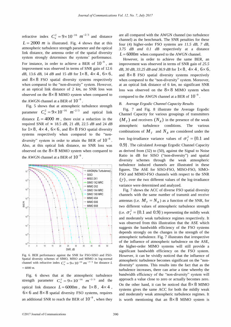
Figs. 4, 5 and 6 show the BER performance analysis of
various FSO spatial diversity channels from the single-
order (SISO) FSO system up to very high-order MIMO
FSO systems (such as 44 , 66 and 88 MIMO
systems) as a function of the SNR, for atmospheric
turbulence strength parameter of 162 109 nC 3/2m ,
representing the weak atmospheric turbulence regime,
with three diverse optical link distances (i.e. 2 km, 4 km
and 6 km). These figures depict the influence of the
various optical link distances over the BER performance
of various antenna order configurations of the spatial
diversity FSO system.
Fig. 5. BER performance against the SNR for FSO-SISO and FSO-Spatial diversity schemes of SIMO, MISO and MIMO in log-normal
channel with refractive index 162 109 nC 3/2m for distance
L = 4000 m.
From Fig. 4, the BER performance analysis for the
SISO-FSO, MISO-FSO, SIMO-FSO and the MIMO-FSO
systems over the Log-normal fading channel with
390
Journal of Communications Vol. 12, No. 7, July 2017
©2017 Journal of Communications
refractive index 162 109 nC
3/2m and distance
2000L m is illustrated. Fig. 4 shows that at this
atmospheric turbulence strength parameter and the optical
link distance, the antenna order of the spatial diversity
system strongly determines the systems’ performance.
For instance, in order to achieve a BER of 910
, an
improvement was observed in terms of SNR gain of 12.6
dB, 13.6 dB, 14 dB and 15 dB for 81 , 44 , 66 ,
and 88 FSO spatial diversity systems respectively
when compared to the “non-diversity” system. However,
at an optical link distance of 2 km, no SNR loss was
observed on the 88 MIMO system when compared to
the AWGN channel at a BER of 910
.
Fig. 5 shows that at atmospheric turbulence strength
parameter 162 109 nC 3/2m and optical link
distance 4000L m , there exist a reduction in the
required SNR of 18.5 dB, 21 dB, 22.5 dB and 24 dB
for 81 , 44 , 66 , and 88 FSO spatial diversity
systems respectively when compared to the “non-
diversity” system in order to attain the BER of 910
.
Also, at this optical link distance, no SNR loss was
observed on the 88 MIMO system when compared to
the AWGN channel at a BER of 910
.
Fig. 6. BER performance against the SNR for FSO-SISO and FSO-
Spatial diversity schemes of SIMO, MISO and MIMO in log-normal
channel with refractive index 162 109 nC3/2m for distance L
= 6000 m.
Fig. 6 shows that at the atmospheric turbulence
strength parameter 162 109 nC3/2m and the
optical link distance 6000L m , the 81 , 44 ,
66 and 88 spatial diversity FSO systems, requires
an additional SNR to reach the BER of 910
, when they
are all compared with the AWGN channel (no turbulence
channel) as the benchmark. The SNR penalties for these
four (4) higher-order FSO systems are 11.5 dB, 7 dB,
3.75 dB and 0.1 dB respectively at a distance
6000L m when compared to the AWGN channel.
However, in order to achieve the same BER, an
improvement was observed in terms of SNR gain of 25.5
dB, 30 dB, 33.25 dB and 36.9 dB for 81 , 44 , 66 ,
and 88 FSO spatial diversity systems respectively
when compared to the “non-diversity” system. Moreover,
at an optical link distance of 6 km, no significant SNR
loss was observed on the 88 MIMO system when
compared to the AWGN channel at a BER of 910
.
B. Average Ergodic Channel Capacity Results
Fig. 7 and Fig. 8 illustrate the Average Ergodic
Channel Capacity for various groupings of transmitters
)( TM and receivers )( RN in the presence of the weak
atmospheric turbulence conditions. The various
combinations of TM and RN are considered under the
two log-irradiance variance values of 1.0{2 I and
}9.0 . The calculated Average Ergodic Channel Capacity
as derived from (32) to (50), against the Signal to Noise
Ratio in dB for SISO (“non-diversity”) and spatial
diversity schemes through the weak atmospheric
turbulence induced channels are illustrated in these
figures. The ASE for SISO-FSO, MISO-FSO, SIMO-
FSO and MIMO-FSO channels with respect to the SNR
)( , over the two different values of the log-irradiance
variance were determined and analyzed.
Fig. 7 shows the ACC of diverse FSO spatial diversity
channels with the same number of transmit and receive
antennas (i.e. RT NM ) as a function of the SNR, for
two different values of atmospheric turbulence strength
(i.e. 1.0{2 I and }9.0 ) representing the mildly weak
and moderately weak turbulence regimes respectively. It
was observed from this illustration that the ASE which
suggests the bandwidth efficiency of the FSO systems
depends strongly on the changes in the strength of the
atmospheric turbulence. Fig. 7 illustrates that irrespective
of the influence of atmospheric turbulence on the ASE,
the higher-order MIMO systems will still provide a
significant bandwidth efficiency on the FSO system.
However, it can be vividly noticed that the influence of
atmospheric turbulence becomes significant on the "non-
diversity" systems. This results into the fact that as the
turbulence increases, there can arise a time whereby the
bandwidth efficiency of the “non-diversity” system will
approach a value close to zero or actually becomes zero.
On the other hand, it can be noticed that 88 MIMO
systems gives the same ACC for both the mildly weak
and moderately weak atmospheric turbulence regimes. It
is worth mentioning that an 88 MIMO system is

391
Journal of Communications Vol. 12, No. 7, July 2017
©2017 Journal of Communications
unaffected by the level of turbulence within the range of
the weak atmospheric turbulence regime, whereby at
SNR of 30 dB it yields a bandwidth efficiency of up to 71
bps/Hz. Using the "non-diversity" FSO system as the
benchmark, at SNR of 30 dB, we noticed a bandwidth
efficiency gain of 63 bps/Hz, 45 bps/Hz, 27 bps/Hz and
8 bps/Hz for 88 , 66 , 44 and 22 MIMO
systems respectively at 9.02 I .
Fig. 7. Ergodic channel capacity analysis for FSO-SISO and FSO-
Spatial diversity systems over a log-normal channel with 1.02 I
and 9.02 I .
Fig. 8 shows the ACC of diverse FSO spatial diversity
channels with the different number of transmit and
receive antennas (i.e. RT NM ) as a function of the
SNR, for atmospheric turbulence strength 9.02 I
representing the moderately weak turbulence regime.
This explains the disparity in the Average (Ergodic)
Channel Capacity of the transmit diversity against the
receive diversity with MRC technique. Also in this figure,
using the "non-diversity" system as the benchmark, at
9.02 I , we deduced that the bandwidth efficiency
provided by the receive diversity systems with MRC
technique is far greater than that obtained from the
transmit diversity. As the order of the spatial diversity
increases, a tremendous increase in ACC was noticed.
This suggests that the higher-order SIMO spatial diversity
systems provide significant improvement to the ACC.
Therefore, using the "non-diversity" FSO system as the
benchmark, at SNR of 30 dB, we noticed that the ACC
gain was approximately 1 bps/Hz for 18 transmit
diversity FSO system, while it extends up to 24 bps/Hz,
16 bps/Hz, 8 bps/Hz and 6.5 bps/Hz for 81 , 61 ,
41 and 21 receive diversity FSO systems
respectively.
Therefore, from Figs. 7 and 8, it can be noticed that
channel performance improves only if there is an increase
in the number of transmit and receive antennas. But this
is greatly noticed when there is an increase in the receive
antennas, suggesting that the MIMO and SIMO FSO
systems provide a better channel performance than the
SISO and MISO FSO systems considered. However,
from the analysis, it is clearly noticed that the ACC
depends strongly on the strength of the atmospheric
turbulence which determines the log-irradiance variance
value. As the log irradiance variance values increases, the
ACC of the considered systems reduces.
Fig. 8. Ergodic Channel Capacity analysis for transmit and receive FSO-
Spatial diversity systems over a log-normal channel with 9.02 I .
C. Outage Probability Results
The CDFs of the channel capacities for the spatial
diversity FSO systems under the Log-normal fading are
illustrated in Figs. 9 and 10 when the SNR is 10 dB and
20 dB respectively, at optical link distance L = 6 km,
optical wavelength 850 nm and the atmospheric
turbulence strength 162 109 nC
3/2m . Fig. 9
illustrates the CDF of some spatial diversity FSO systems
as a function of the transmission rate R, at SNR of 10 dB,
optical link distance L = 6 km and under a weak
turbulence condition of atmospheric turbulence strength 162 109 nC 3/2m . At the indicated OCC of
1.0 , it can be observed that the higher-order spatial
diversity systems yields significant data rate of 5.25
b/s/Hz, 7 b/s/Hz, 11.3 b/s/Hz, 11.6 b/s/Hz and 15.5 b/s/Hz
for 42 , 44 , 66 , 84 and 88 MIMO FSO
systems. However, it can also be noticed that the 84
and 66 MIMO FSO systems have almost the same
data rate at 1.0 when the SNR is 10 dB, despite the
difference in their antenna order configurations. In
contrast, as expected, the “non-diversity” FSO system
(SISO) shows no significant improvement in its channel
capacity unlike the spatial diversity FSO systems.

392
Journal of Communications Vol. 12, No. 7, July 2017
©2017 Journal of Communications
Fig. 9. Cumulative Distribution Function of the FSO-SISO and FSO-
Spatial diversity channel capacities as a function of the transmission rate
over a Log-normal channel with 162 109 nC 3/2m , at SNR = 10
dB and distance L = 6 km.
Fig. 10 illustrates the CDF of some spatial diversity
FSO systems as a function of the transmission rate R, at
SNR of 20 dB, optical link distance L = 6 km and under
atmospheric turbulence strength 162 109 nC3/2m .
At the indicated OCC of 1.0 , the data transmission
rate of the higher-order spatial diversity systems are 11
b/s/Hz, 16.5 b/s/Hz, 24 b/s/Hz, 26 b/s/Hz and 35.5 b/s/Hz
for 42 , 44 , 84 , 66 and 88 MIMO FSO
systems, while the “non-diversity” FSO system yields a
data rate of 2.5 b/s/Hz.
Fig. 10. Cumulative Distribution Function of the FSO-SISO and FSO-
Spatial diversity channel capacities as a function of the transmission rate
over a Log-normal channel with 162 109 nC 3/2m , at SNR = 20
dB and distance L = 6 km.
However, when the SNR is 20 dB, one of the notable
facts is that at 1.0 , the CDF of the 84 and 66
MIMO systems are not quite close unlike the CDF at
SNR = 10 dB. The 66 MIMO system has a data rate
gain of about 2 b/s/Hz over the 84 MIMO system
when the SNR increases from 10 dB to 20 dB. This can
also be as a result of the fact that the number of channels
of the 66 MIMO system is greater than that of the
84 MIMO system. Thus, these two figures (9 and 10)
have shown that channel capacities of the higher-order
spatial diversity FSO systems improve optimally as the
number of the transmit antennas and receive antennas
increases.
V. CONCLUSION
The optical SISO and spatial diversity systems
employing the BPSK-SIM across optical sources with
Coherent Detection over the Log-normal model for weak
atmospheric turbulence condition, with two chosen
scintillation indices have been analyzed. The two
scintillation indices for this analysis were given in terms
of the log-irradiance variance values of 1.02 I and
9.02 I , respectively representing mildly weak and
moderately weak atmospheric turbulence conditions. The
analyses made in this report were necessary for observing
the best performance improvement that can ever be
obtained from higher-order spatial diversity systems for
Free Space Optical communications. This knowledge can
be used to avoid reduction in transmission capacity as
well as any possible outages. However, according to the
results of the BER performance analysis for all the
scenarios considered, it was observed that the SNR (dB)
needed to obtain an optimal BER increases along with the
increase in the atmospheric turbulence level which is
indicated by the scintillation indices. Among the higher-
order spatial diversity systems that were considered under
the weak atmospheric turbulence regime, 88 MIMO
system gave the optimum BER and channel capacity
performances.
Therefore, the efficiency and power of the higher-order
spatial diversity system especially the 88 MIMO
system was established in the presence of weak
atmospheric turbulence and considered for average BER
of 910
. As a matter of fact, it is important to note that
as the spatial diversity antenna order configuration
increases, there exist a practical complexity limitation
introduced into the system. This practical limitation is as
a result of the complexities of the higher-order spatial
diversity techniques with higher number of transmit and
receive antennas involved in the build-up of the FSO
communication system design. This makes it complicated
in the practical sense. This form of advance spatial
diversity techniques has been suggested to provide
improvement on the system performance in FSO
communications when considering relatively severe
scintillation channels.
Thus, when implementation is not focused on the
complexity of the design, higher-order spatial diversity
techniques and BPSK-SIM can be employed in FSO

393
Journal of Communications Vol. 12, No. 7, July 2017
©2017 Journal of Communications
communications through channels that are induced by
atmospheric turbulence. This results into improving the
FSO link performance as well as to reduce transmission
power.
ACKNOWLEDGMENT
One of the authors of this paper hereby wishes to
acknowledge the financial support of the University of
KwaZulu-Natal, Durban, South Africa, towards his on-
going PhD.
REFERENCES
[1] E. Bayaki, R. Schober, and R. K. Mallik, “Performance
analysis of MIMO free-space optical systems in gamma-
gamma fading,” IEEE Transactions on Communications,
vol. 57, no. 11, pp. 3415–3424, 2009.
[2] K. Prabu and D. S. Kumar, “BER analysis of DPSK–SIM
over MIMO free space optical links with misalignment,”
Optik-International Journal for Light and Electron Optics,
vol. 125, no. 18, pp. 5176–5180, 2014.
[3] S. M. Aghajanzadeh and M. Uysal, “Diversity–
multiplexing trade-off in coherent free-space optical
systems with multiple receivers,” Journal of Optical
Communications and Networking, vol. 2, no. 12, pp. 1087–
1094, 2010.
[4] X. Zhu and J. M. Kahn, “Free-space optical
communication through atmospheric turbulence channels,”
IEEE Transactions on Communications, vol. 50, no. 8, pp.
1293–1300, 2002.
[5] T. H. Duyen and A. T. Pham, “Performance analysis of
MIMO/FSO systems using SC-QAM signaling over
atmospheric turbulence channels,” IEICE Transactions on
Fundamentals of Electronics, Communications and
Computer Sciences, vol. 97, no. 1, pp. 49–56, 2014.
[6] X. Tang, S. Rajbhandari, W. O. Popoola, Z. Ghassemlooy,
E. Leitgeb, S. S. Muhammad, and G. Kandus,
“Performance of BPSK subcarrier intensity modulation
free-space optical communications using a log-normal
atmospheric turbulence model,” in Proc. Symposium on
Photonics and Optoelectronic, 2010, pp. 1–4.
[7] M. Ijaz, Z. Ghassemlooy, H. L. Minh, S. Rajbhandari, and
J. Perez, “Analysis of fog and smoke attenuation in a free
space optical communication link under controlled
laboratory conditions,” in Proc. International Workshop on
Optical Wireless Communications, 2012, pp. 1–3.
[8] Y. Gao, M. Wu, and W. Du, “Performance research of
modulation for optical wireless communication system,”
Journal of Networks, vol. 6, no. 8, pp. 1099–1105, 2011.
[9] J. Park, E. Lee, and G. Yoon, “Average bit-error rate of the
Alamouti scheme in gamma-gamma fading channels,”
Photonics Technology Letters, vol. 23, no. 4, pp. 269–271,
2011.
[10] B. Barua and D. Barua, “Evaluate the performance of FSO
communication link with different modulation technique
under turbulent condition,” in Proc. 14th International
Conference on Computer and Information Technology,
2011, pp. 191–195.
[11] A. Garcıa-Zambrana, C. Castillo-V azquez, and B.
Castillo-V´azquez, “On the capacity of FSO links over
gamma-gamma atmospheric turbulence channels using
OOK signaling,” EURASIP Journal on Wireless
Communications and Networking, p. 64, 2010.
[12] O. A. Layioye, T. J. O. Afullo, and P. A. Owolawi,
“Variation of altitude on the variance of angle of arrival
fluctuations for beam propagation in free space optical
communications,” in Proc. 3rd IEEE International
Conference on Advances in Computing Communication
and Engineering, 2016, pp. 120-125.
[13] H. D. Trung, D. H. Ai, and A. T. Pham, “Average channel
capacity of free-space optical MIMO systems over
atmospheric turbulence channels,” The University of Aizu
Aizuwakamatsu-shi, Fukushima, Japan, 2014, pp. 965–
8580.
[14] H. D. Trung, B. T. Vu, and A. T. Pham, “Performance of
free space optical MIMO systems using SC-QAM over
atmospheric turbulence channels,” in Proc. IEEE
International Conference on Communications, 2013, pp.
3846–3850.
[15] S. Zvanovec, J. Perez, Z. Ghassemlooy, S. Rajbhandari,
and J. Libich, “Route diversity analyses for free-space
optical wireless links within turbulent scenarios,” Optics
Express, vol. 21, no. 6, pp. 7641–7650, 2013.
[16] B. Barua and D. Barua, “Channel capacity of MIMO FSO
system under strong turbulent condition,” IJECS-IJENS,
vol. 11, no. 2, 2011.
[17] J. Li, J. Q. Liu, and D. P. Taylor, “Optical communication
using subcarrier PSK intensity modulation through
atmospheric turbulence channels,” IEEE Transactions on
Communications, vol. 55, no. 8, pp. 1598–1606, 2007.
[18] C. Abou-Rjeily, “On the optimality of the selection
transmit diversity for MIMO-FSO links with feedback,”
Communications Letters, IEEE, vol. 15, no. 6, pp. 641–643,
2011.
[19] E. Bayaki and R. Schober, “Performance and design of
coherent and differential space-time coded FSO systems,”
Journal of Lightwave Technology, vol. 30, no. 11, pp.
1569–1577, 2012.
[20] O. A. Layioye, T. J. O. Afullo, and P. A. Owolawi,
“Calculations of the influence of diverse atmospheric
turbulence conditions on free space optical communication
system using BPSK-SIM over the gamma-gamma model,”
in Proc. South Africa Telecommunications Networks and
Applications Conference, Western Cape, South Africa,
2016, pp. 362-367.
[21] Z. Chen, S. Yu, T. Wang, G. Wu, H. Guo, and W. Gu,
“Spatial correlation for transmitters in spatial MIMO
optical wireless links with gaussian-beam waves and
aperture effects,” Optics Communications, vol. 287, pp.
12–18, 2013.
[22] J. Zhang, L. Dai, Y. Han, Y. Zhang, and Z. Wang, “On the
ergodic capacity of MIMO free-space optical systems over
turbulence channels,” IEEE Journal on Selected Areas in
Communications, vol. 33, no. 9, pp. 1925–1934, 2015.
[23] K. P. Peppas and P. T. Mathiopoulos, “Free-Space optical
communication with spatial modulation and coherent
394
Journal of Communications Vol. 12, No. 7, July 2017
©2017 Journal of Communications
detection over HK atmospheric turbulence channels,”
Journal of Lightwave Technology, vol. 33, no. 20, pp.
4221–4232, 2015.
[24] M. Safari and S. Hranilovic, “Diversity and multiplexing
for near-field atmospheric optical communication,” IEEE
Transactions on Communications, vol. 61, no. 5, pp. 1988–
1997, 2013.
[25] W. O. Popoola and Z. Ghassemlooy, “BPSK subcarrier
intensity modulated free-space optical communications in
atmospheric turbulence,” Journal of Lightwave Technology,
vol. 27, no. 8, pp. 967–973, 2009.
[26] S. M. Haas and J. H. Shapiro, “Capacity of wireless optical
communications,” IEEE Journal on Selected Areas in
Communications, vol. 21, no. 8, pp. 1346–1357, 2003.
[27] E. J. Lee and V. W. S. Chan, “Diversity coherent receivers
for optical communication over the clear turbulent
atmosphere,” in Proc. International Conference on
Communications, 2007, pp. 2485–2492.
[28] X. Song, M. Niu, and J. Cheng, “Error rate of subcarrier
intensity modulations for wireless optical
communications,” Communications Letters, vol. 16, no. 4,
pp. 540–543, 2012.
[29] A. T. Pham, T. C. Thang, S. Guo, and Z. Cheng,
“Performance bounds for turbo-coded SC-PSK/FSO
communications over strong turbulence channels,” in Proc.
International Conference on Advanced Technologies for
Communications, 2011, pp. 161–164.
[30] S. G. Wilson, M. Brandt-Pearce, M. Baedke, and Q. Cao,
“Optical MIMO transmission with multipulse PPM,” in
Proc. International Symposium on Information Theory,
2004, p. 289.
[31] S. G. Wilson, M. Brandt-Pearce, Q. Cao, and J. H.
Leveque III, “Free-Space optical MIMO transmission with
Q-ary PPM,” IEEE Transactions on Communications, vol.
53, no. 8, pp. 1402–1412, 2005.
[32] S. G. Wilson, M. Brandt-Pearce, Q. Cao, and M. Baedke,
“Optical repetition MIMO transmission with multipulse
PPM,” IEEE Journal on Selected Areas in
Communications, vol. 23, no. 9, pp. 1901–1910, 2005.
[33] D. A. Luong and A. T. Pham, “Average capacity of MIMO
free-space optical gamma-gamma fading channel,” in Proc.
IEEE International Conference on Communications, 2014,
pp. 3354–3358.
[34] C. E. Shannon, “A mathematical theory of
communication,” ACM SIGMOBILE Mobile Computing
and Communications Review, vol. 5, no. 1, pp. 3–55, 2001.
[35] D. A. Luong, C. T. Truong, and A. T. Pham, “Effect of
APD and thermal noises on the performance of SC-
BPSK/FSO systems over turbulence channels,” in Proc.
18th Asia-Pacific Conference on Communications, 2012,
pp. 344–349.
[36] Y. S. Cho, J. Kim, W. Y. Yang, and C. G. Kang, MIMO-
OFDM Wireless Communications with MATLAB, John
Wiley & Sons, 2010.
[37] K. D. Rao, Channel Coding Techniques for Wireless
Communications, Springer, 2015.
Okikiade A. Layioye received his B. Tech degree in Physics
(with Electronics) from the Federal University of Technology,
Akure, in 2008. He holds a Masters degree in Electronic
Communications and Computer Engineering from the
University of Nottingham, England, United Kingdom in 2012.
He is currently a PhD student at the University of KwaZulu-
Natal, Durban, South Africa. His research interests are in optical
communications, wireless communications, telecommunications
engineering and electronic communications.
Thomas J. O. Afullo is a Professor of Electronic Engineering
and he was the former Discipline Academic Leader of the
School of Electrical, Electronic and Computer Engineering at
the University of KwaZulu-Natal, Durban, South Africa. He has
about 36 years working experience in the Telecommunications
industry and academia. His research interests are in modeling of
radio wave propagation, telecommunications engineering,
wireless networks and power line communications.
Pius A. Owolawi is a professor and HOD of the Department of
Computer Engineering at Tshwane University of Technology,
Pretoria, South Africa. He received his B.Tech degree in
Physics/Electronics from the Federal University of Technology,
Akure, in 2001. He obtained an MSc and PhD degrees in
Electronic Engineering from the University of KwaZulu-Natal
in 2006 and 2010, respectively. His research interests are in the
modeling of radio wave propagation, fiber optic communication,
radio planning and optimization techniques.