Embed Size (px)
Citation preview
1
PEMFC Electrodes
2
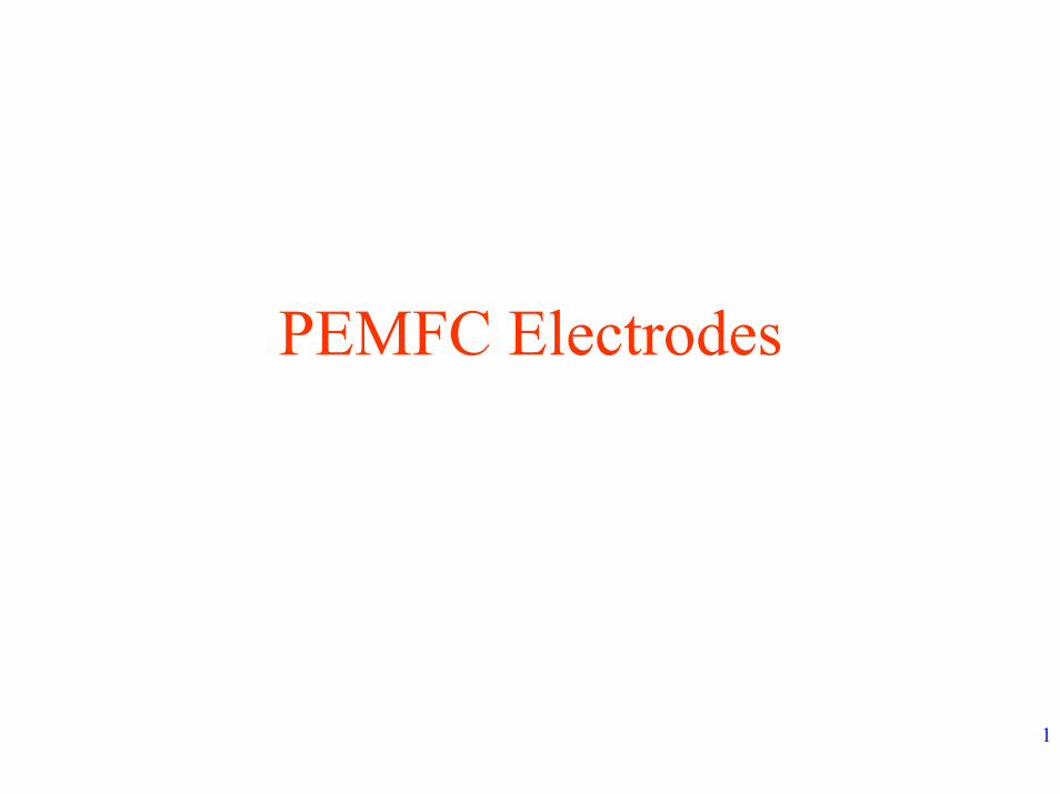
Cross Section of Proton Exchange Membrane Fuel CellCross Section of Proton Exchange Membrane Fuel Cell
Anode Cathode
3
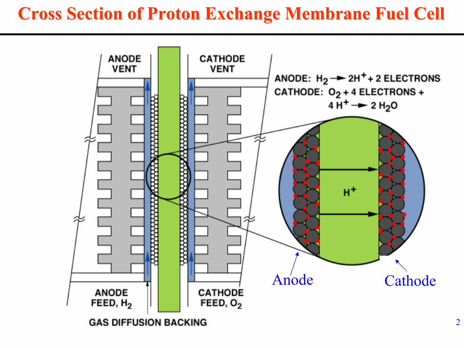
Typical PEMFC
• Electrodes:- Anode – Hydrogen Oxidation
- Pt – Ru / C
- Cathode – Oxygen reduction- Pt / C
Pt is alloyed with Ru to enhance CO tolerance of Anode electrocatalyst
4
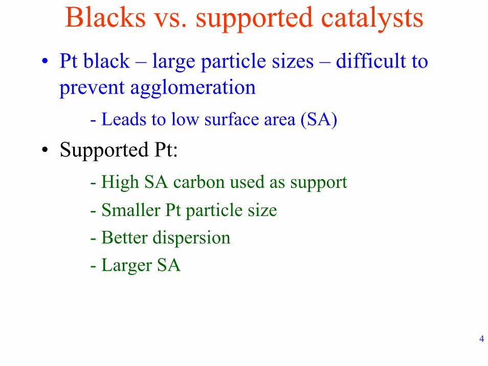
Blacks vs. supported catalysts• Pt black – large particle sizes – difficult to
prevent agglomeration- Leads to low surface area (SA)
• Supported Pt:- High SA carbon used as support- Smaller Pt particle size- Better dispersion- Larger SA
5
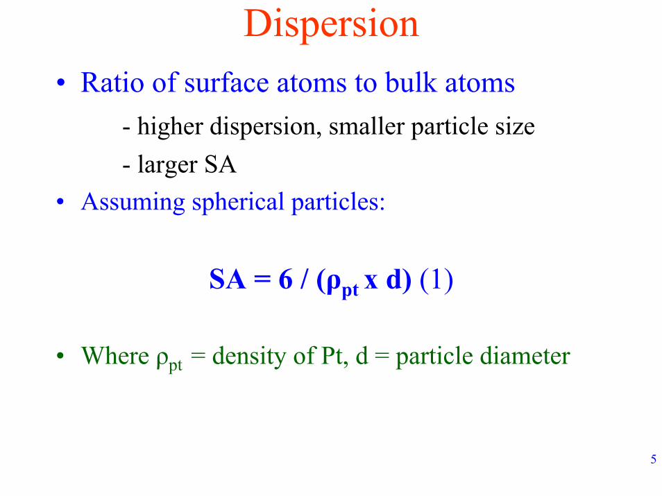
Dispersion• Ratio of surface atoms to bulk atoms
- higher dispersion, smaller particle size- larger SA
• Assuming spherical particles:
SA = 6 / (ρpt x d) (1)
• Where ρpt = density of Pt, d = particle diameter
6
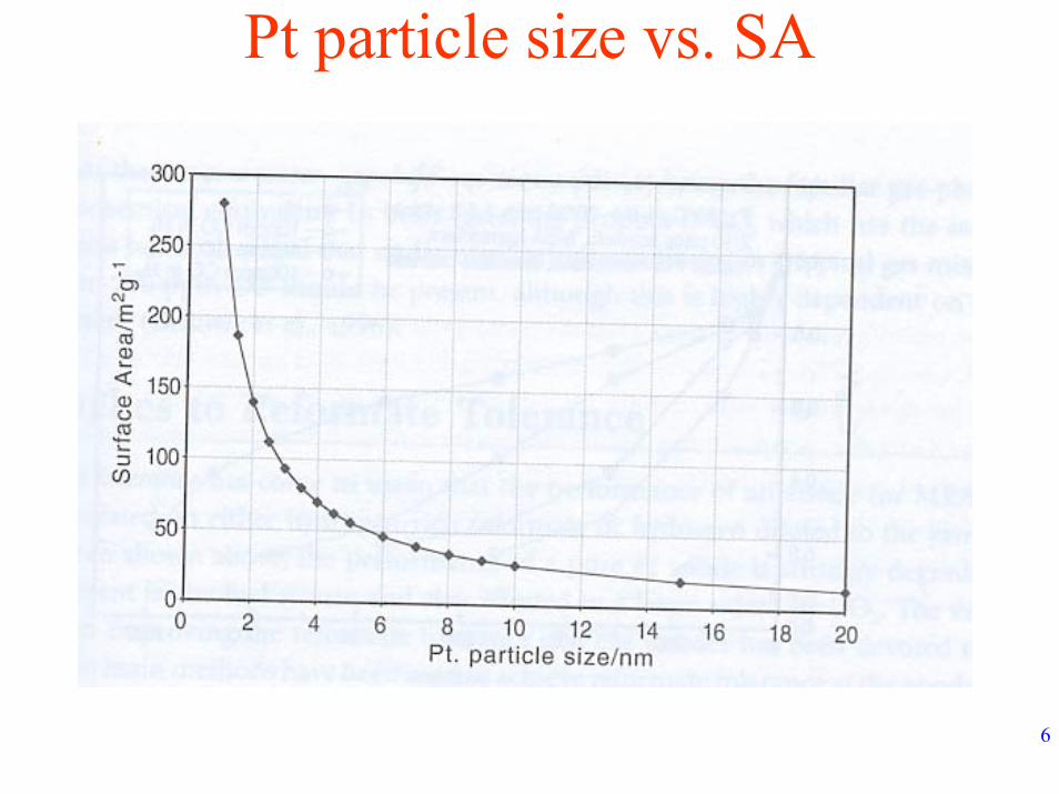
Pt particle size vs. SA
7
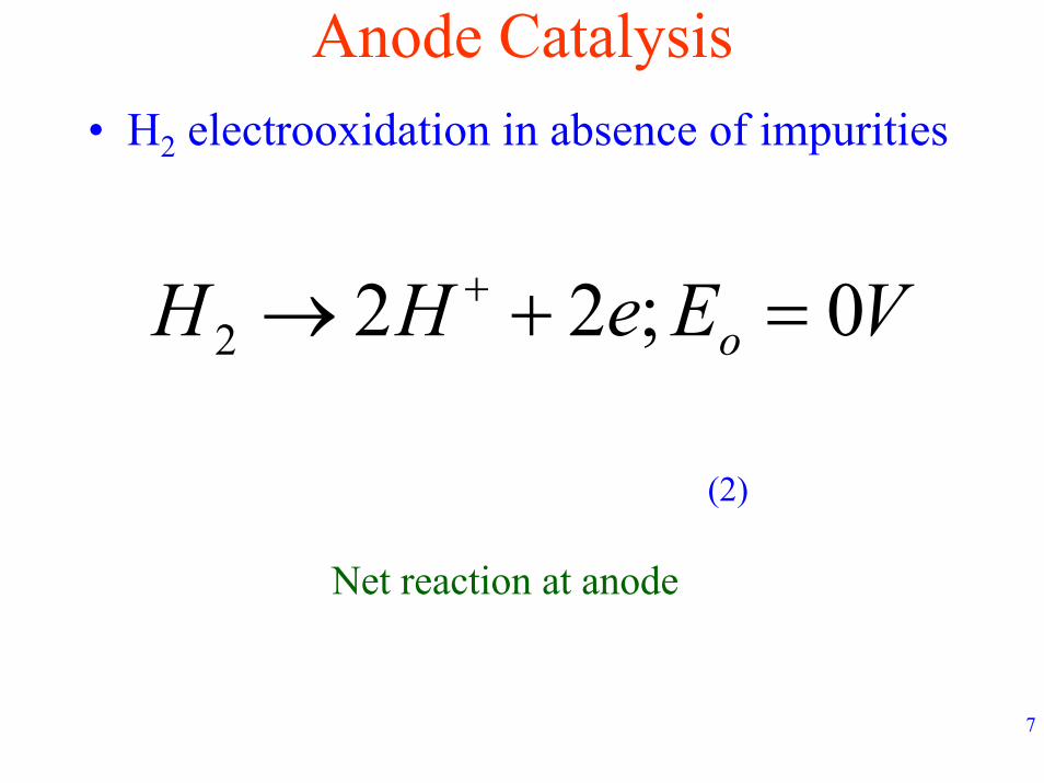
Anode Catalysis• H2 electrooxidation in absence of impurities
VEeHH o 0;222 =+→ +
(2)
Net reaction at anode
8
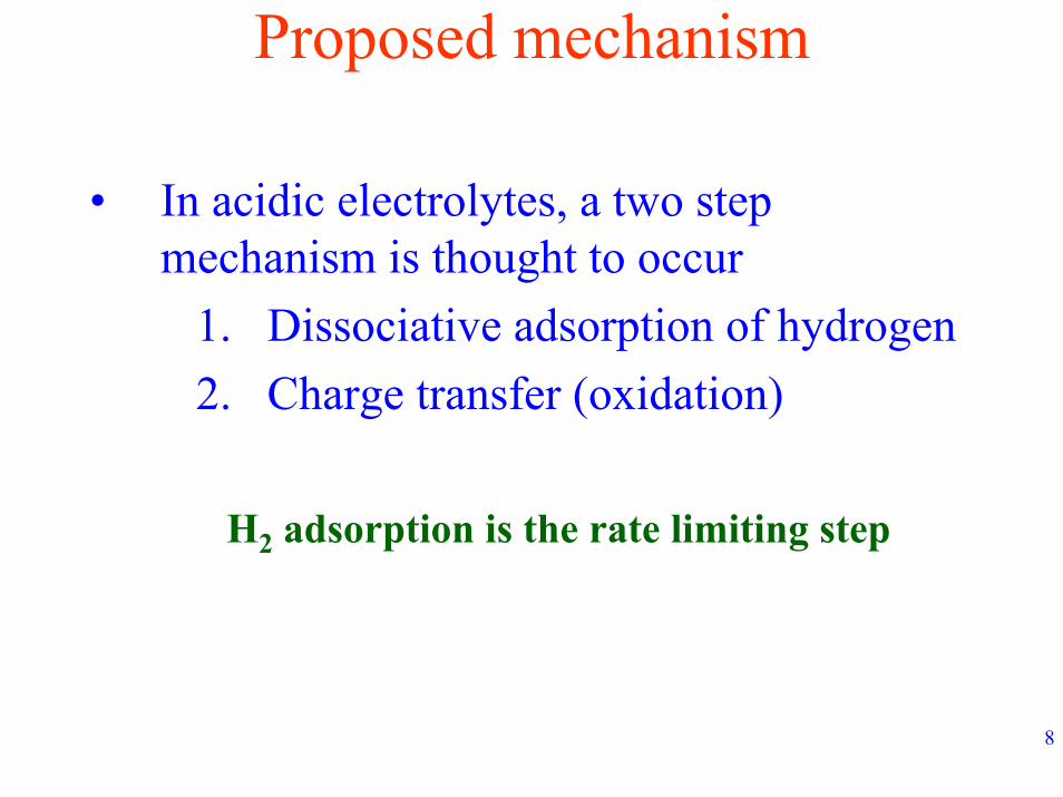
Proposed mechanism
• In acidic electrolytes, a two step mechanism is thought to occur
1. Dissociative adsorption of hydrogen2. Charge transfer (oxidation)
H2 adsorption is the rate limiting step
9
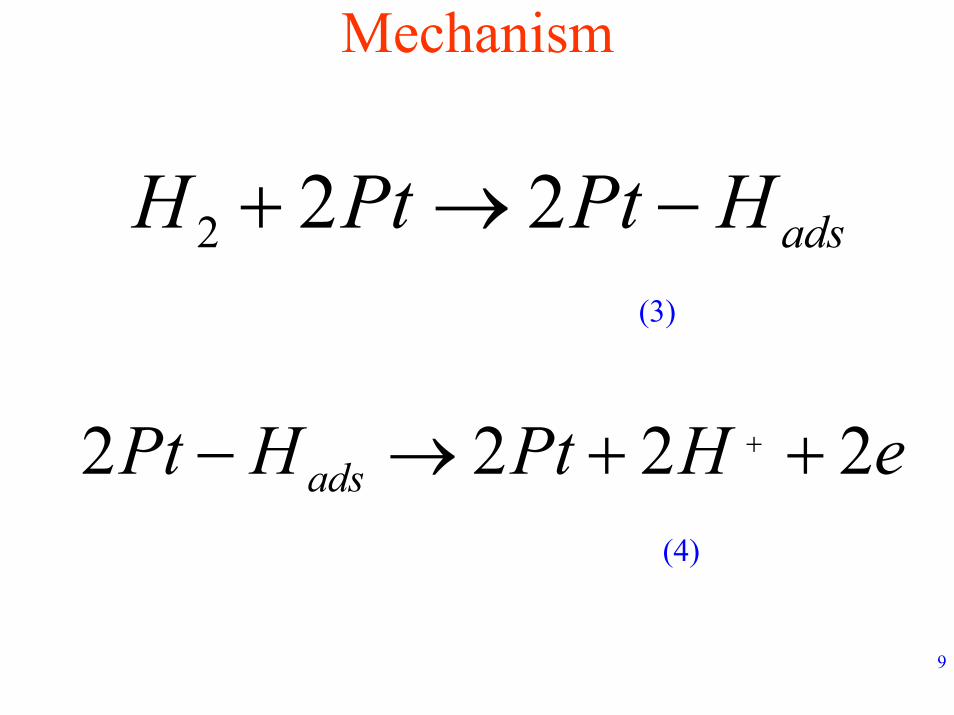
Mechanism
adsHPtPtH −→+ 222(3)
eHPtHPt ads 2222 ++→− +
(4)
10
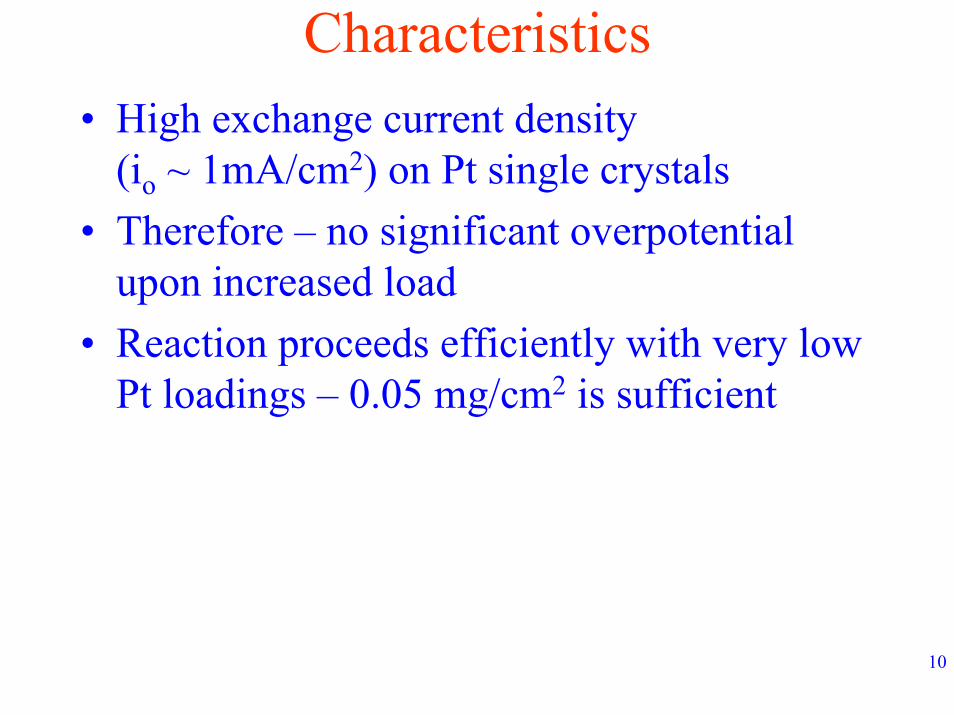
Characteristics• High exchange current density
(io ~ 1mA/cm2) on Pt single crystals• Therefore – no significant overpotential
upon increased load• Reaction proceeds efficiently with very low
Pt loadings – 0.05 mg/cm2 is sufficient
11
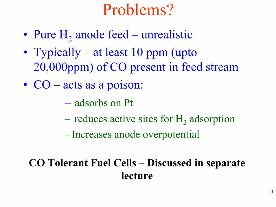
Problems?• Pure H2 anode feed – unrealistic• Typically – at least 10 ppm (upto
20,000ppm) of CO present in feed stream• CO – acts as a poison:
– adsorbs on Pt– reduces active sites for H2 adsorption– Increases anode overpotential
CO Tolerant Fuel Cells – Discussed in separate lecture
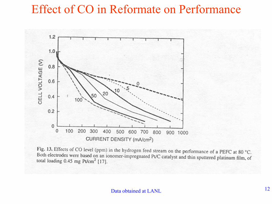
Data obtained at LANL 12
Effect of CO in Reformate on Performance
13
Cathode electrolysis• Oxygen reduction reaction
OHeHO 22 244 →++ +
(5)
14
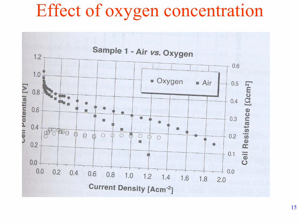
Characteristics• Lower exchange current density (10-4 to 10-6
mA/cm2) on Pt• Much higher overpotential (compared to pure
H2 oxidation) for a given current density• Higher loadings (0.4 mg/cm2) needed• Kinetics – strong function of oxygen partial
pressure (0.7 – 1 order)
15
Effect of oxygen concentration
16
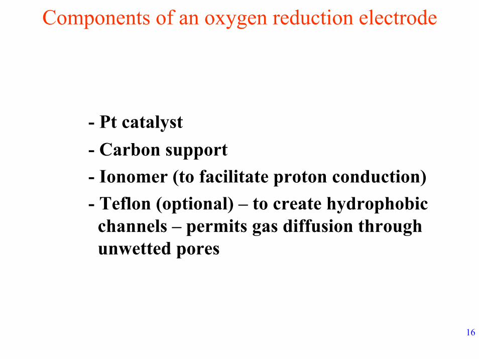
Components of an oxygen reduction electrode
- Pt catalyst- Carbon support- Ionomer (to facilitate proton conduction)- Teflon (optional) – to create hydrophobic
channels – permits gas diffusion through unwetted pores
17
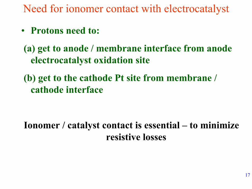
Need for ionomer contact with electrocatalyst
• Protons need to:
(a) get to anode / membrane interface from anode electrocatalyst oxidation site
(b) get to the cathode Pt site from membrane / cathode interface
Ionomer / catalyst contact is essential – to minimize resistive losses
18
Oxygen transport• Reactant interaction with Pt – crucial (recall
strong kinetic dependence on concentration of Oxygen)
• Thus viable path for oxygen transport needed
• Places limitation on electrode thickness and composition
19
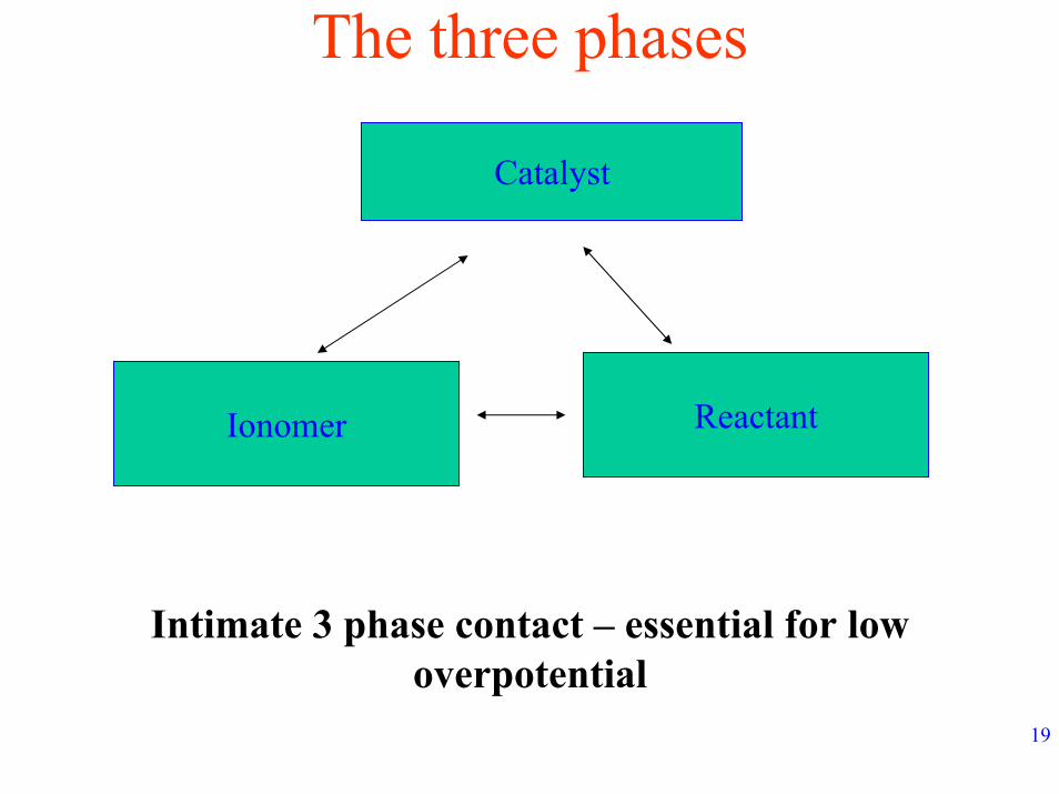
The three phases
Catalyst
Ionomer Reactant
Intimate 3 phase contact – essential for low overpotential
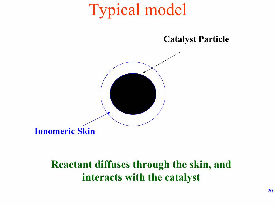
20
Typical modelCatalyst Particle
Ionomeric Skin
Reactant diffuses through the skin, and interacts with the catalyst
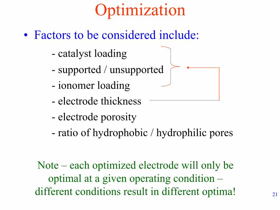
21
Optimization• Factors to be considered include:
- catalyst loading- supported / unsupported- ionomer loading- electrode thickness- electrode porosity- ratio of hydrophobic / hydrophilic pores
Note – each optimized electrode will only be optimal at a given operating condition –
different conditions result in different optima!
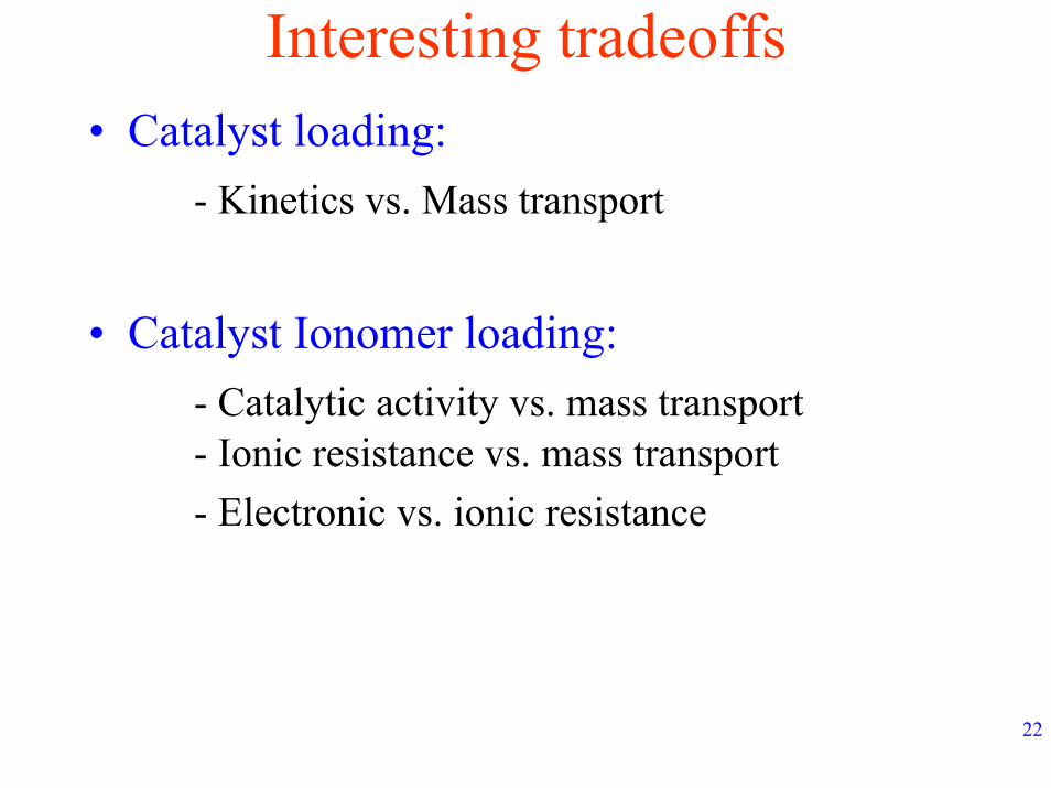
22
Interesting tradeoffs• Catalyst loading:
- Kinetics vs. Mass transport
• Catalyst Ionomer loading:- Catalytic activity vs. mass transport - Ionic resistance vs. mass transport- Electronic vs. ionic resistance
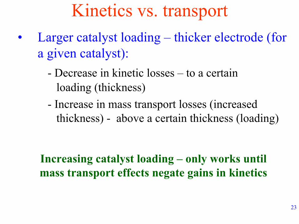
23
Kinetics vs. transport• Larger catalyst loading – thicker electrode (for
a given catalyst):- Decrease in kinetic losses – to a certain
loading (thickness)- Increase in mass transport losses (increased
thickness) - above a certain thickness (loading)
Increasing catalyst loading – only works until mass transport effects negate gains in kinetics
24
A caveat• Recall – catalysts are typically Pt supported
on carbon• Increasing the % of Pt/C – higher Pt density
per gram of catalyst• For given Pt loading (and ionomer content):
- lower electrode thickness with increasing Pt content in Pt/C catalyst
Note that Pt surface area decreases with increasing Pt loading in Pt/C - lower catalyst utilization
25
Ionomer loading• Note that:
- Ionomer presence is essential- Homogeneous distribution required- Must intertwine with Pt particles
• Also recall:- Good ionomer – does not permit large reactant crossover
- Low oxygen permeability through ionomer - Diffusional problems!- Good ionomer – does not conduct electrons
26
Catalytic activity vs. mass transport• Large ionomer loading:
- Good contacting with Pt particles- High catalyst utilization- High catalytic activity
• However:- Large ionomeric skin thickness (slide 20)- Enhanced diffusional losses
27
Ionic resistance vs. mass transport• Large ionomer loading:
- Good ionomeric network between catalyst site and membrane electrode interface
- High proton conductivity / transport- Low resistive losses
• However:- Large ionomeric skin thickness (slide 20)- Enhanced diffusional losses
28
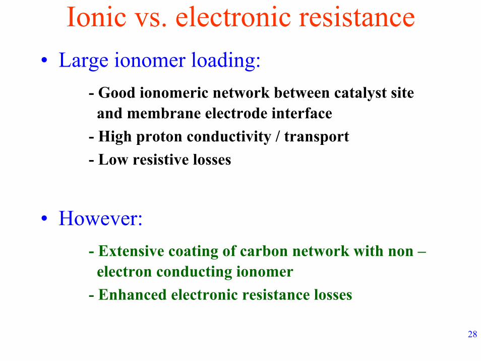
Ionic vs. electronic resistance• Large ionomer loading:
- Good ionomeric network between catalyst site and membrane electrode interface
- High proton conductivity / transport- Low resistive losses
• However:- Extensive coating of carbon network with non –electron conducting ionomer
- Enhanced electronic resistance losses
29
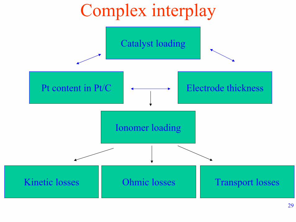
Complex interplay
Catalyst loading
Pt content in Pt/C Electrode thickness
Ionomer loading
Kinetic losses Ohmic losses Transport losses
30
OptimizationExtremely challenging – difficult to manipulate
single parameters
Optimal compositions change with type of catalyst –even from manufacturer to manufacturer
Optimal compositions certainly change with operating conditions
31
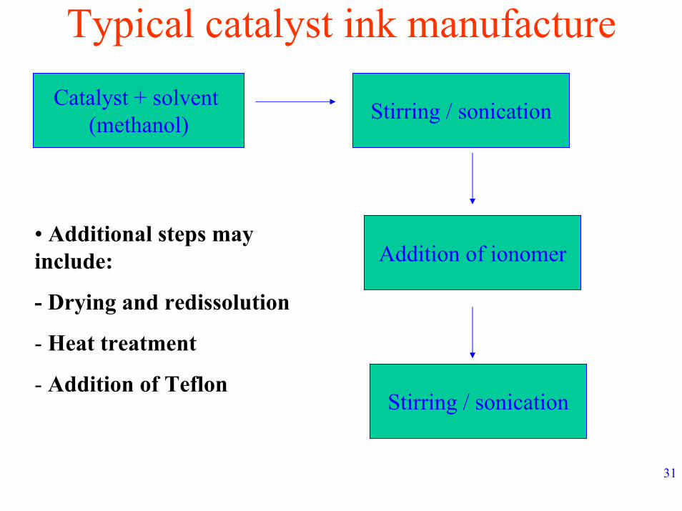
Typical catalyst ink manufactureCatalyst + solvent
(methanol) Stirring / sonication
• Additional steps may include:
- Drying and redissolution
- Heat treatment
- Addition of Teflon
Addition of ionomer
Stirring / sonication
32
Added complexity• Variables in catalyst ink manufacture:
- Temperature of ink manufacture- Type / extent of agitation - Heat treatment- Solvent used……
Any change in above – results in different optimal compositions for any given condition
33
Yet another parameter – MEA manufacturing technique
• Several techniques of applying catalyst to membrane
• Broad subdivision:- Catalyst applied to membrane- Catalyst applied to gas diffusion layer
34
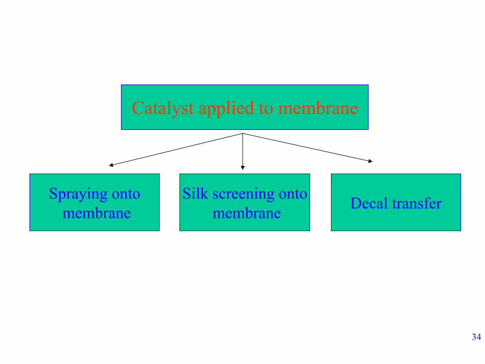
Catalyst applied to membrane
Spraying ontomembrane
Silk screening ontomembrane Decal transfer
35
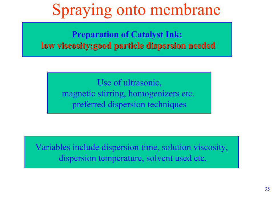
Spraying onto membranePreparation of Catalyst Ink:
low viscosity;good particle dispersion neededlow viscosity;good particle dispersion needed
Use of ultrasonic,magnetic stirring, homogenizers etc.
preferred dispersion techniques
Variables include dispersion time, solution viscosity,dispersion temperature, solvent used etc.
36
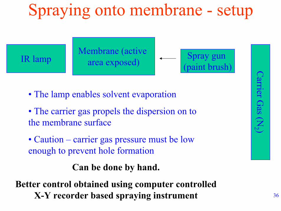
Spraying onto membrane - setup
Membrane (active area exposed)
Spray gun (paint brush)
IR lamp
Carrier G
as (N2 )
• The lamp enables solvent evaporation
• The carrier gas propels the dispersion on to the membrane surface
• Caution – carrier gas pressure must be low enough to prevent hole formation
Can be done by hand.
Better control obtained using computer controlled X-Y recorder based spraying instrument

37
Silk screeningPreparation of Catalyst Ink:
higher viscosity;good particle dispersion neededhigher viscosity;good particle dispersion needed
Use of ultrasonic,magnetic stirring, homogenizers etc.
preferred dispersion techniques –viscosity controlled by
external agents such as ethylene glycol
Variables include dispersion time, solution viscosity,dispersion temperature, solvent used etc.
38
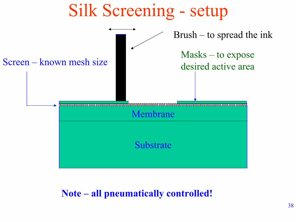
Silk Screening - setup
Substrate
Membrane
Masks – to expose desired active area
Brush – to spread the ink
Screen – known mesh size
Note – all pneumatically controlled!
39
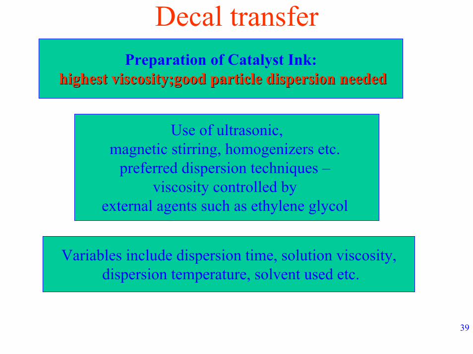
Decal transferPreparation of Catalyst Ink:
highest viscosity;good particle dispersion neededhighest viscosity;good particle dispersion needed
Use of ultrasonic,magnetic stirring, homogenizers etc.
preferred dispersion techniques –viscosity controlled by
external agents such as ethylene glycol
Variables include dispersion time, solution viscosity,dispersion temperature, solvent used etc.
40
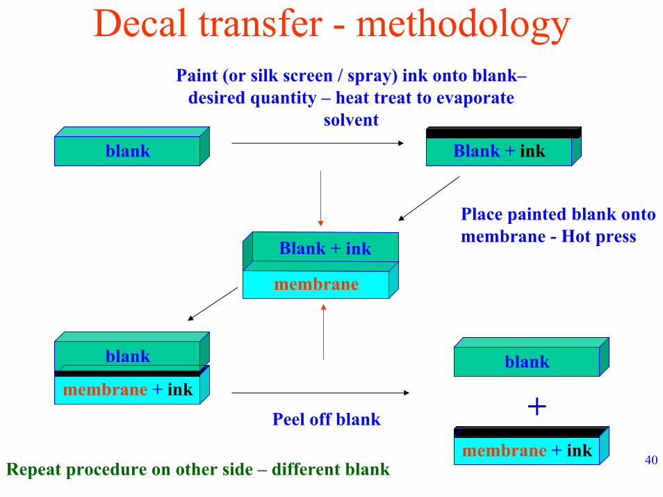
Decal transfer - methodology
Blank + ink
Paint (or silk screen / spray) ink onto blank–desired quantity – heat treat to evaporate
solvent
blank
membrane
Place painted blank onto membrane - Hot press Blank + ink
blankblank
membrane + ink+Peel off blank
membrane + inkRepeat procedure on other side – different blank
41
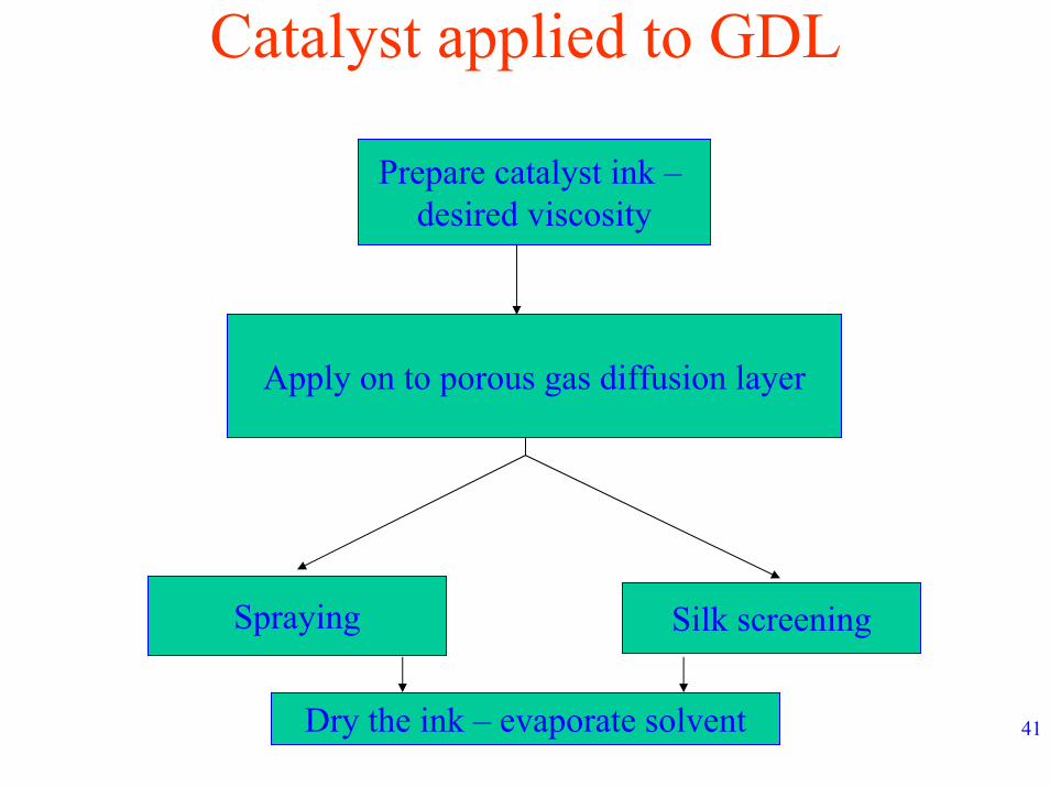
Catalyst applied to GDL
Prepare catalyst ink –desired viscosity
Apply on to porous gas diffusion layer
Spraying Silk screening
Dry the ink – evaporate solvent
42
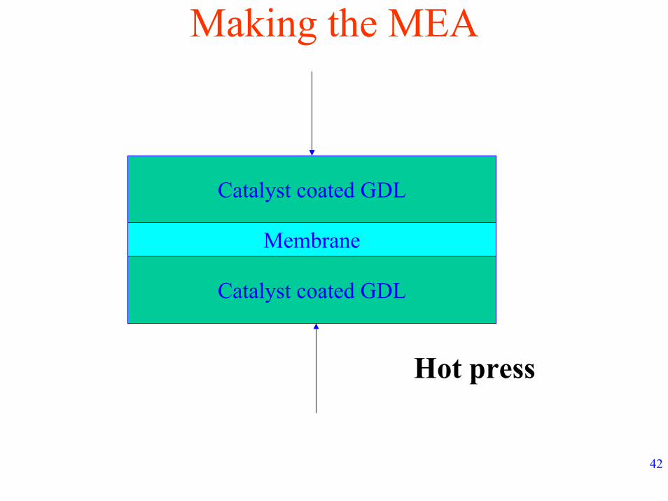
Making the MEA
Catalyst coated GDL
Catalyst coated GDL
Membrane
Hot press
43
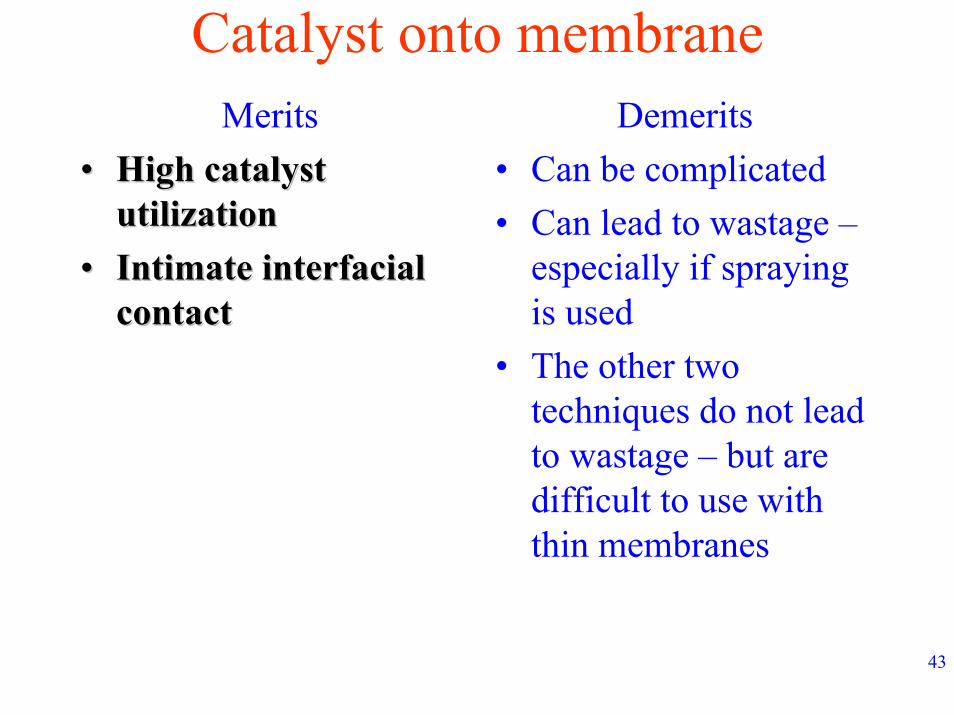
Catalyst onto membraneMerits
•• High catalyst High catalyst utilizationutilization
•• Intimate interfacial Intimate interfacial contact
Demerits• Can be complicated• Can lead to wastage –
especially if spraying is used
• The other two techniques do not lead to wastage – but are difficult to use with thin membranes
contact
44
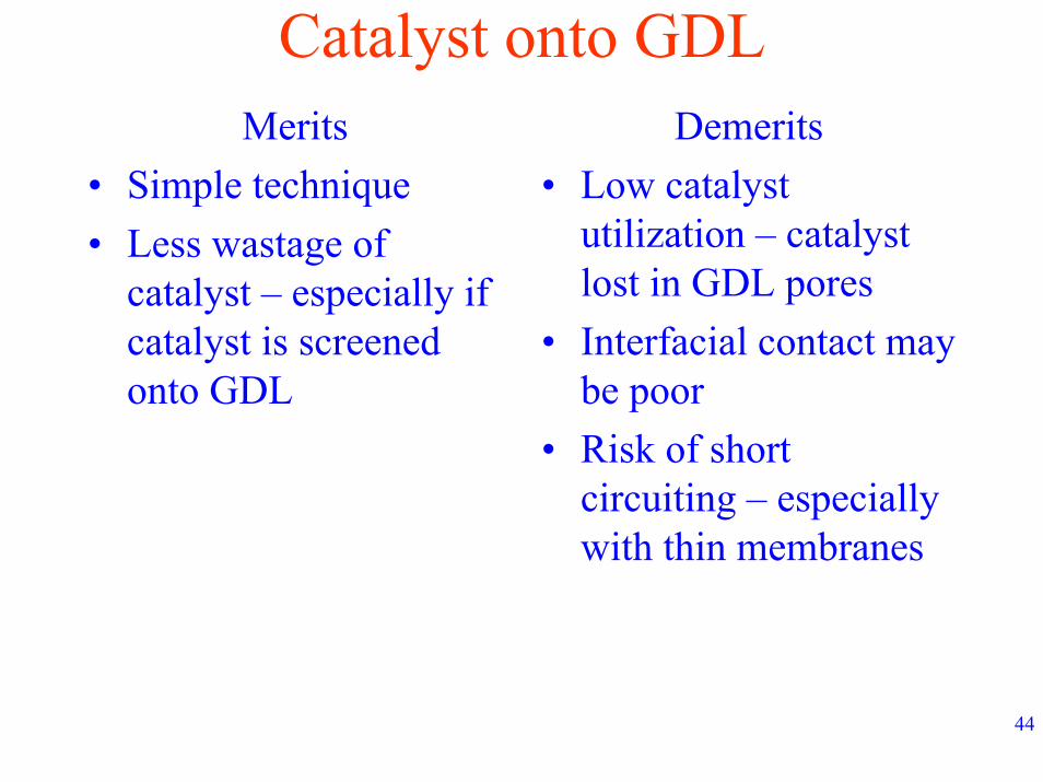
Catalyst onto GDLDemerits
• Low catalyst utilization – catalyst lost in GDL pores
• Interfacial contact may be poor
• Risk of short circuiting – especially with thin membranes
Merits• Simple technique• Less wastage of
catalyst – especially if catalyst is screened onto GDL
45
RemarksOn the whole, applying the catalyst onto the
membrane is the preferred technique for high performance
Decal transfer – with catalyst inks screened on to the surface of the blank – most elegant
technique – good reproducibility