Embed Size (px)
Citation preview
Project 05510 – Automatic Committee BoatPreliminary Design Review
February 18, 2005
Team Leader: Cory HoffmanLead Engineer: Victoria ParnellComputer Engineer: Phil MaskelonyElectrical Engineer: Michael MoranElectrical Engineer: Tristan Petersen

Executive Summary
This document provides a synopsis of the progress made by the Automatic Committee Boat Senior Design Team (Project 05510). The objective to be fulfilled by the team is to design an Automatic Committee Boat (ACB) to be implemented for the Summer of 2005. Project 05510 is sponsored by the Pultneyville Yacht Club which races during the summer season on Lake Ontario. Currently, members of the club are designated to sit on the committee boat and raise a series of flags and sound a horn to start the race. These members must wait approximately two hours for the race to finish and then record the finish times of each vessel. The sponsor noted that “sailor’s want to race” and would prefer the maximum inclusion of members in the race. An Automatic Committee Boat was proposed. In general, the goal of the Automatic Committee Boat is to replace a physical member of the yacht club by raising a series of flags, sounding a horn, and recording the race finish.
The process as outlined in EDGETM was followed for the design of the ACB. As delineated in the table of contents, five major design steps were used to create the proposed design. These include: recognizing and quantifying the need, concept development, feasibility assessment, performance objectives and specifications, analysis and synthesis, and finally a plan for future work in Senior Design II. As of the end of Senior Design I, the ACB team is on schedule with the original project plan. There are design details and questions, however, that require further investigation from the team and censoring from the sponsor. These issues will be included with the first phase of Senior Design II which is Engineering Models and Detailed Design.
Using the design process presented during lectures, the team arrived at the proposed design for the ACB as contained in this document. It consists of a pneumatic system for raising and lowering the flags, a controller for timing the flag raising sequence, and finally a microcontroller for calculating and adjusting the heading of a VHS camcorder used in race finish imaging. In more detail, the valve operated pneumatics (with a pressurized supply tank) are controlled by a Crouzet Millenium II controller. This visually programmed controller will send voltage signals at a designated time to the air supply valves, thus controlling the double-acting pneumatic cylinders. For the race finish timing, a VHS camcorder will be used to record vessels crossing the finish line. A microcontroller along with a compass mounted to the camera, will calculate the heading of the camera and adjust accordingly (via a motor connected to a turntable) in order to compensate for the drift of the ACB. The entire system will run on a 12 Volt battery supply and be remotely operated with an RF transmitter and receiver.
A proposed design is contained in the final sections of this report along with a bill of materials. This technical package contains drawings of the pneumatics and system housing. Block diagrams and code are also provided in the Appendix for both controllers.
1

PDR Technical Document OutlineItem Page No.Executive Summary..............................................................................................................1Table of Contents..................................................................................................................2List of Figures.......................................................................................................................41.0 Recognize and Quantify the Need..................................................................................5
1.1 Project Mission Statement..................................................................................51.2 Project Description..............................................................................................51.3 Scope Limitations ..............................................................................................71.4 Stake Holders .....................................................................................................81.5 Key Business Goals............................................................................................81.6 Financial Analysis...............................................................................................81.7 Preliminary Market ............................................................................................91.8 Secondary Market...............................................................................................91.9 Order Qualifiers..................................................................................................91.10 Order Winners..................................................................................................111.11 Innovation Opportunities.................................................................................121.12 Other................................................................................................................12
2.0 Concept Development....................................................................................................122.1 Flag Raising Concepts.......................................................................................13
2.1.1 Pneumatically Raised Flagpole.................................................................132.1.2 Telescoping Flagpole................................................................................142.1.3 Inflatable Flagpole....................................................................................142.1.4 Motor and Counterweight.........................................................................142.1.5 Motor and Spring Types I and II...............................................................142.1.6 Motor and Gearing....................................................................................15
2.2 System Housing Concepts ................................................................................152.3 Control System Concepts...................................................................................16
2.3.1 DMX Control............................................................................................162.3.2 Hardware Playback Device.......................................................................182.3.3 Hardware Implementation........................................................................182.3.4 Micro-controller........................................................................................182.3.5 PLC Style Controller.................................................................................19
2.4 Finish Imaging Concepts...................................................................................192.4.1 VHS Video Imaging.................................................................................202.4.2 Digital Camera Image Processing.............................................................202.4.3 Motion Detected Image Capture...............................................................202.4.4 RFID Telemetry........................................................................................212.4.5 Encoded Clock..........................................................................................21
2.5 Zero Mark Tracking Concepts...........................................................................212.5.1 Video Recognition....................................................................................222.5.2 Global Positioning System........................................................................222.5.3 Magnetic Compass....................................................................................222.5.4 RF Telemetry............................................................................................232.5.5 IR Telemetry.............................................................................................23
2.6 Remote Communication Concepts....................................................................23
2

2.6.1 “Garage Door” Style Communication......................................................242.6.2 Infra-Red...................................................................................................242.6.3 Talk-about.................................................................................................242.6.4 Wireless Fidelity Communication............................................................25
2.7 Concept Integration............................................................................................253.0 Feasibility Assessment...................................................................................................26
3.1 Flag Raising Feasibility.....................................................................................263.2 System Housing Feasibility...............................................................................283.3 Control System Feasibility.................................................................................283.4 Finish Imaging Feasibility.................................................................................293.5 Zero Mark Tracking Feasibility.........................................................................303.6 Remote Communication Feasibility..................................................................313.7 Feasibility Conclusion ......................................................................................32
4.0 Performance Objectives and Specifications...................................................................334.1 Design Objectives .............................................................................................334.2 Performance Specifications ..............................................................................334.3 Design Practices Used by the Team...................................................................344.4 Safety Issues.......................................................................................................35
5.0 Analysis of Problem and Synthesis of Design...............................................................355.1 Vessel Design and Analysis...............................................................................36
5.1.1 Buoyancy..................................................................................................365.1.2 Stability.....................................................................................................37
5.2 Flag Raising System..........................................................................................375.2.1 Air pressure and volume ..........................................................................395.2.2 Force to raise flags....................................................................................415.2.3 Stress Analysis..........................................................................................44
5.3 Remote Communication Design and Analysis..................................................455.4 Camera Motion Control and Imaging................................................................45
5.4.1 VHS Camera.............................................................................................465.4.2 Variation in Location and Direction.........................................................475.4.3 Compass....................................................................................................475.4.4 Microcontroller and Motor.......................................................................48
5.5 Control System Design and Analysis................................................................485.6 System Housing and Analysis...........................................................................515.7 Power Supply Design and Analysis...................................................................51
5.7.1 Battery Selection.......................................................................................515.7.2 Electrical Load..........................................................................................52
5.7.2.1 Battery Operating Life.................................................................535.8 Analysis Conclusion .........................................................................................53
6.0 Future Plans ..................................................................................................................556.1 Experimentation.................................................................................................576.2 Budget ...............................................................................................................57
7.0 Conclusion.....................................................................................................................57References............................................................................................................................58Appendix
3

List of Figures:
1.) Overall System Schematic (pg. 33)
2.) Dinghy Envelope Drawing (pg. 36)
3.) Pneumatic Schematic (pg. 38)
4.) Working Model Simulation (pg. 40)
5.) Crouzet Programming Sample (pg. 50)
6.) Component Power Requirements (pg. 53)
7.) System Housing (pg. 54)
8.) System Assembly (pg. 54)
9.) Senior Design II Gantt Chart (pg. 55)
10.) Bill of Materials (pg. 57)
4

1.0 Recognize and Quantify the Need
The Automatic Committee Boat Project Team recognized the importance of listing key
requirements in a formal document and having all parties involved with the project agree to
the terms. First, the team developed a list of rules that explicitly stated the expectations held
for members. This document was signed by all members of the team and can be seen in
Appendix A. Second, the team worked closely with the sponsor to develop a Needs
Assessment document which listed all project “qualifiers” and “winners.” This document
was signed by all team members as well as the sponsor (see Appendix B). Having a written
list of these requirements prevents future discrepancies between the team and sponsor as to
what exactly are the desired outcomes of the project. Additionally, a Gantt chart was
developed to keep the team on track and organized (See Appendix N).
1.1 Project Mission Statement
The mission of the design project team is to design an automatic committee boat to replace a
physical member of the Pultneyville Yacht Club in performing the race start sequence of
flags and horns as well as the recording of the race finish.
1.2 Project Description
The Automatic Committee Boat Project is sponsored by the Pultneyville Yacht Club (PYC).
From May through September, members of the club race various styles of boats around a
predetermined course in a harbor of Lake Ontario. Currently, one member must volunteer to
sit out each race in order to manually perform the start sequence of flags and horns from the
committee boat (or dinghy). Therefore, the Pultneyville Yacht club has sponsored this senior
5

design project in which an automated committee boat (ACB) will be developed to eliminate
the need for a manual race start sequence. The ACB is intended to be self operating, after
being towed into position, with no direct contact by the remote operator (see Appendix C) for
PYC requirements).
The start sequence is executed as follows:
“Warning”: Five minutes before the race starts, Class 1 Flag goes up with gun “Preparatory”: Four minutes before the race starts, P Flag goes up with horn “One minute”: 1 minute before the race starts, P flag goes down with horn “Start”: Class 1 Flag goes down with gun “Warning”: Five minutes before the race starts, Class 2 Flag goes up with gun “Preparatory”: Four minutes before the race starts, P Flag goes up with horn “One minute”: 1 minute before the race starts, P flag goes down with horn “Start plus”: Class 2 Flag goes down with gun
Therefore, each race sequence contains three flags; the P flag is raised twice while the Class
1 and Class 2 flags are raised once. This results in a total of four flag raises per sequence.
In addition to performing the race start sequence, the ACB must also produce an image of the
race finish. The image must include an anchored buoy that is located approximately 300 feet
away from the committee boat. This buoy is referred to as the “zero-mark.” Passing
between the committee boat and the zero-mark constitutes finishing the race. Both the
dinghy and the zero-mark will experience drift as the wind and lake current change
directions. Therefore, it is necessary that the team develop a method of tracking the zero
mark with the selected imaging device.
As previously mentioned, the ACB is intended to be self operating with no direct contact by
the operator. Therefore, the team must also design a technique that will allow PYC members
to remotely communicate with the dinghy. The club expressed that they require the
capability to start, stop, restart, and test the automated system from their individual boats,
6

which will be approximately 300 feet away from the committee boat. The test sequence is
required by PYC so that the members can ensure that each component of the system is
operating properly.
Overall, the Automatic Committee Boat Team is responsible for developing the software
logic, electrical circuitry, and mechanical designs that will be necessary to meet the
requirements proposed by the Pultneyville Yacht Club.
1.3 Scope Limitations
The Automatic Committee Boat shall fulfill all expectations as per Pultneyville Yacht Club
required specifications. The ACB shall be completely designed by February 18, 2005 and a
working prototype shall be developed by the end of May, 2005.
The total cost of the project shall not exceed $800. The completed design shall fit within envelope of a provided dinghy and maintain
stability and buoyancy of the vessel. The completed design shall withstand the typical outdoor conditions experienced
from May through September. First consideration shall be given to commercially available products. The design shall assume low volume manufacturing cost considerations.
The team is responsible for meeting the following deliverables by February 18, 2005:
Complete drawing package Technical data package and report Complete Bill of Materials and list of vendors Budget plan Schedule plan for Senior Design II
The team is responsible for meeting the following deliverables by May, 2005:
Demonstrated use of a working prototype
7

Final report Future recommendations
The team shall not be responsible for any of the following:
Anchoring system In harbor maneuvering Tow-line adjustment Bilge pump Storage canvas
1.4 Stake Holders
The main stake holders of the ACB project include various members of the Pultneyville
Yacht Club and race committee members. Additional stakeholders include senior design
teams that could be working on a second generation Automatic Committee Boat project as an
interest in this was expressed by the sponsor.
1.5 Key Business Goals
The Automatic Committee Boat project Team will be deemed successful when a remotely
operated ACB exists that meets all specifications outlined in the signed Needs Assessment
document to automatically control the race start sequence of the Pultneyville Yacht Club and
record the race finish.
1.6 Financial Analysis
All development and implementation costs of the ACB must not exceed $800. ACB
production is limited to one unit for the Pultneyville Yacht Club resulting in a unique and
specialized product.
8

1.7 Preliminary Market
The preliminary market of the Automatic Committee Boat project is the Pultneyville Yacht
Club. The PYC is made up of members from all over the greater Rochester area; some are as
far away as Canaseraga, North Rose, and Bloomfield.
1.8 Secondary Market
The secondary market of the ACB project includes similar boating and/or yachting clubs that
partake in various forms of racing activities. Therefore, future application of the design
shall be taken into consideration for groups such as these.
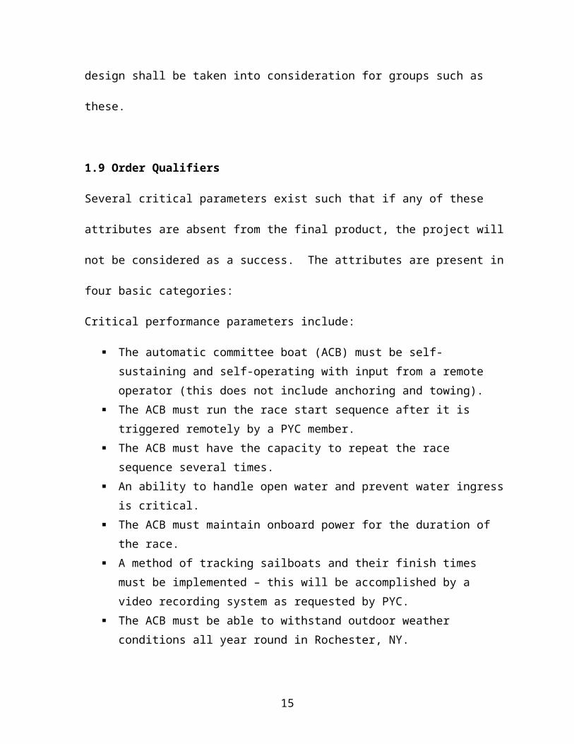
1.9 Order Qualifiers
Several critical parameters exist such that if any of these attributes are absent from the final
product, the project will not be considered as a success. The attributes are present in four
basic categories:
Critical performance parameters include:
The automatic committee boat (ACB) must be self-sustaining and self-operating with input from a remote operator (this does not include anchoring and towing).
The ACB must run the race start sequence after it is triggered remotely by a PYC member.
The ACB must have the capacity to repeat the race sequence several times. An ability to handle open water and prevent water ingress is critical. The ACB must maintain onboard power for the duration of the race. A method of tracking sailboats and their finish times must be implemented – this will
be accomplished by a video recording system as requested by PYC. The ACB must be able to withstand outdoor weather conditions all year round in
Rochester, NY. The ACB must be portable and compatible with different types of vessels.
9

A method of tracking the zero mark must be implemented. Camera must have the ability to view over the bow of the boat next to the video
recorder. Quick access to the recorded media is a must. A test mode must be implemented in design to ensure that all components are
functioning properly.
Critical scheduling parameters include:
The design must be completed for implementation during the 2005 race year (summer).
The robust design must be useable with little to no maintenance for an entire racing period (one summer).
All major design process steps must be communicated with the PYC steering committee and scheduled appropriately.
Meetings with program coordinator must be held at least three to four times per quarter.
Critical technological parameters include:
The ACB must be remotely controlled. The ACB shall have onboard logistics capable of controlling several mechanized
systems. System power must be sustained for the length of the race. A system for recording video of the race finish must be included in the design. A method of coordinating flag and sound signals through system logic must be
developed. Remote control should be possible for a distance of up to 300 feet.
Critical economic parameters include:
The ACB must be designed and implemented within the budget of $800. Design must utilize provided dinghy and or other designated vessel. Design must not require modification of provided vessel (depreciation of vessel)
10

1.10 Order Winners
Several attributes exist that would result in a design that is ahead of the competition. These
characteristics are present in four basic categories and will be implemented if time and
budget permit:
Critical performance parameters include:
Data download should be quick ACB should have a method of remote steering through harbor passages ACB should have a delay of race flag ACB should have a random start where the start sequence begins within the next two
minutes. A method of self-anchoring should be included. Inexpensive universal remotes should be used.
Critical scheduling parameters include:
System start-up should be quick and allow sufficient time for the towing vessel to clear and prepare for racing
System set-up and tear-down should be quick
Critical technological parameters include:
ACB components should be corrosion resistant The ACB should be self-anchoring A warning beep should be implemented when a zero mark signal is not received. A beep for two seconds should sound when the finish line is blocked except for the
first four minutes after the race starts. A method of transmitting intermittent data to the shore should be included. Bilge pump operation should be controlled by the system. A method for indicating the battery power remaining should be included in the final
design. Air pressure level indicators should be included – if air is included in design.
11

Critical economic parameters include:
ACB should have the potential for use in other yacht clubs Design should not cause damage to supporting vessel or tow vessel (destruction of
capital).
1.11 Innovation Opportunities
Opportunities largely exist in systems integration and component design. Programming code
will be unique to the system. The pneumatic housing and assembly is also open to the team’s
design. Zero-mark tracking will consist of a unique method for controlling the direction of
an image capturing device. No discussion of patent ownership/authorship has been covered.
1.12 Other
In addition to the above needs, the following items are true:
A steering committee will be provided by PYC A vessel will be provided by PYC for design implementation It is recommended that the team should consist of Computer Engineering, Electrical
Engineering, and Mechanical Engineering backgrounds
2.0 Concept Development
To facilitate the concept development phase of the design process, the Automatic Committee
Boat team divided the project into several subsystems that were evaluated separately. After
numerous concepts were developed for each of these subsystems, the team utilized the
“group drawing” method to brainstorm system integration concepts (see Appendix D for all
concept sketches). The project was split into the following six categories:
Flag Raising - method of raising and lowering the four flags that make up the race start sequence
12

System Housing – the container that will store and protect all equipment from the outdoor environment
Control System – the “brains” of the system Finish Imaging – method of obtaining an image of the race finish Zero Mark Tracking – method of keeping the imaging equipment directed towards
the finish line Remote Communication – method used to interface with the control system to
remotely start/stop/restart/pause the race sequence
Where applicable, the team conducted a preliminary concept assessment to eliminate ideas
that were clearly impractical. This reduced the number of concepts to a manageable size for
an efficient, thorough feasibility assessment. The individual subsystems and the concepts
developed for them are examined more closely in sections 2.1 through 2.6.
2.1 Flag Raising Concepts
The flag raising subsystem consists of all mechanical and electrical equipment that is
required to raise and lower the three flags that are used in the race start sequence. The horn
required in the sequence is also included in this subsystem. The Automatic Committee Boat
team developed nearly twenty different ideas for raising and lowering the flags. Through a
preliminary concept assessment, this list was reduced to seven ideas which are explained in
detail in sections 2.1.1 through 2.1.7.
2.1.1 Pneumatically raised flagpole
The pneumatically raised flagpole is a concept in which the flagpole will be raised and
lowered through the use of a double acting pneumatic cylinder. A clevis joint at each end
of the cylinder will provide the necessary range of motion for this design. The cylinder
13

will be actuated via a solenoid (or similar valve) that receives a voltage from the control
device. It was suggested that a counterweight could be used at the base of the pole to
reduce the force required to raise the flag.
2.1.2 Telescoping flagpole
The telescoping flagpole concept is a design that would work similar to that of a car
antenna. With this concept, the flag would rise vertically resulting in a very small
footprint. The pole would most likely be powered by a DC motor.
2.1.3 Inflatable flagpole
The next concept consisted of designing an inflatable flagpole. This design would be
similar to a windsock; air would be forced into an enclosed cloth or vinyl material to raise
an attached flag. This design, again, would have a small footprint.
2.1.4 Motor and counter weight
The motor and counter weight concept is an idea where the pole’s pivot point will be
balanced such that it could be raised with a counterweight. To lower the flag, a cable
would be in direct contact with the flag pole and a motor or winch.
2.1.5 Motor and spring types I and II
The motor and spring design operates similarly to the motor and counterweight idea. The
major difference is that a spring would be used instead of a counterweight to raise the
14
flag. A similar concept changes the orientation of the motor and spring. A motor would
raise the flag with the spring supplying the return force.
2.1.6 Motor and gearing
The final design that passed through the preliminary concept assessment is to use a motor
and gearing to raise the flag. A DC motor would be connected to the rotation axis of the
flag via a series of gears. The gearing would reduce the torque requirements on the
motor.
2.2 System Housing Concepts
The system housing subsystem consists of the container and other material that will be used
to protect, transport, and set-up the entire design. It is important that the housing prevent
water ingress and protect all electrical components. Additionally, the design must allow for
an ease of portability for the entire system. This subsystem was treated differently than the
others as the team invoked a brainstorming session to develop key features that the system
housing should possess rather than a list of concepts. The key features are as follows (see
Appendix D for sketches):
Low center of gravity to maintain vessel stability Wire glands should be used to prevent water ingress where input/output lines exist Modular components for ease of trouble shooting Separate battery for ease of recharge As lightweight and inexpensive as possible Corrosion resistant Carrying handles for portability
Since the housing subsystem is dependent on the other subsystem designs, the system
housing concepts could not be developed concurrently with ideas from the other systems.
15

Instead, once a final design was selected for the project, the developed list of key features
was utilized to develop the system housing idea (see section 5.6 for system housing details).
2.3 Control System Concepts
The control system is the “brain” of the automatic committee boat, responsible for
coordinating all of the hardware onboard the vessel. Its primary function is to control the race
start sequence; a sequence of timed events that occur in a specific order. This series of events
is referred to as a “show.” The show consists of raising and lowering three flags at different
points in time, sounding an electronic horn, and rotating an image capturing device to follow
the zero mark. The control system must have the ability to keep time (relative to a zero
point), while triggering the events in a specific order. Furthermore, the system must be
reliable in performing these same actions every time the sequence is activated. It is important
to note that each event in the sequence is controlled by a relay (an electronic switch that uses
a small voltage or current to control a larger voltage or current). The design team evaluated
four control schemes, namely DMX control, hardware playback, hardware implementation,
micro-controller, and PLC style controller. These concepts are detailed below in sections
2.3.1 through 2.3.4.
2.3.1 DMX Control
DMX (digital muliplex) control is perhaps the most complicated control scheme. It is the
industry standard in show and lighting control. In this design, every relay in the system
would have a local DMX interface board, which assigns that piece of equipment a
hardware address. There are a maximum of 512 addresses (devices) allowed in the
16

system without the complication of additional equipment. Each of these pieces of
hardware would be interfaced with a computer via a USB to DMX interface. One key
aspect of this system is the ability to connect the devices in parallel or series. A computer
running DMX control software (Sunlite 2005) would be able to communicate with each
of the devices individually. The software would look for a specific hardware address, and
control only the software addresses located at that position. This implies that each device
may occupy more than one hardware address if the device has more than one channel (a
gobo for example, which contains a beam shutter, gobo, and color wheel). The relays
utilized in this project require only one address per unit. Once the address are
programmed, the control software allows the programmer to drag “blocks” representing
each device onto a timeline, for the time period they are meant to be active. When the
“play” button is pressed, the computer will run the timeline from left to right, triggering
the events as they are encountered. The computer running this software could be a laptop,
or tower portion of a desktop device (to eliminate the need for a power supply). The
computer would need to be powered on at all times. To trigger the show cycle, the RF
receiver would be wired into the analog inputs on the USB to DMX interface board. The
software would be set up so that the activation of this input port would trigger the show
cycle. The intuitive graphic programming interface would allow the yacht club committee
members to easily program multiple shows, with virtually no storage. Switching shows
could be accomplished via software, or a bit more complicatedly through hardware. This
system is also ideal for imaging device control, as the computer could run a separate
software package (perhaps as simple as C-code) to control this device.
17

2.3.2 Hardware Playback Device
A hardware playback device is a solid-state system, capable of storing pre-recorded
sequences that can be played back on demand. This system would be the most reliable, as
there is no computer to freeze up or cause software “glitches”. The design team examined
the SC Master 6/16 from AV Stumpfl, which is programmed with their exclusive Wings
Platinum software. A relay module would be purchased with the device to allow for
simple implementation of hardware activation. The software interface is intuitive to
reduce programming time. The system requires a 120-volt power supply and may lack the
programmability to control the imaging.
2.3.3 Hardware implementation
In this concept, integrated circuit chips (timers, logic gates, etc.) would be used to control
the sequence once the timing of the system was determined. The chips would be soldered
onto a custom circuit board, creating a reliable solid-state device that consumes very little
power. This approach would not allow the program to be changed once it is created.
2.3.4 Micro-controller
A board-based micro-controller is an economical alternative to a computer system. The
controller would be interfaced with a set of relay modules in order to control the exterior
hardware. The controller has easily accessible inputs, supplied with analog to digital
converters. Power requirements are minimal. The controller could be programmed in a
variety of languages including C, Java, and Linux. The programming possibilities are
virtually unlimited with time being the only constraint.
18

2.3.5 PLC Style Controller
A PLC controller is a compact, economical alternative to the aforementioned systems.
This type of controller is most popular in industrial control applications. After
researching this style of controller, the design group chose to more closely examine the
Crouzet Millenium II SA20. Factory equipped with analog and digital inputs, relay
outputs, and PWM (pulse width modulation) outputs, these controllers are suited to
handle virtually any control demand. The programming environment is graphical,
allowing all team members to become fluent in a relatively short time period. Pre-
programmed modules are placed on the workspace and connected with wires. Inputs are
placed in their respective spots on the left with outputs on the right, allowing for intuitive
program flow. A simulator is available to aide in programming without a controller
present.
2.4 Finish Imaging Concepts
A large part of the Automatic Committee Boat project lies in developing a method of
recording the race finish. As per PYC requirements, the system must record an image of
each boat that is crossing the finish line and the zero mark (the buoy).
To record the race finish, the design team developed five concepts using VHS video
recording, a digital camera with image processing, motion detected image capture, RFID
telemetry and an encoded clock. These ideas are detailed below in sections 2.4.1 through
2.4.5. It is important to note that although neither the encoded clock nor the RFID telemetry
19
concepts meet the requirement than an actual image must be produced, the concepts were
included to offer alternative methods in the event that PYC alters the requirements.
2.4.1 VHS Video Recording
The VHS video recording concept utilizes a VHS camcorder to record the finish line
throughout the entire race. A timestamp provided by the camera will be used to track
when the race begins, and when each vessel crosses the finish line. The video will be
reviewed in the boathouse after the race and times and handicaps will be manually
calculated following the current process that PYC uses.
2.4.2 Digital Camera Image Processing
The digital camera image processing concept will take digital photos of the zero line at a
rate between one and three times per second. These captured images will have metadata
associated with them including the time they were taken, and a probability of action. A
program will be used after the race that will allow the race committee to review the
pictures that were likely to contain boats crossing the zero mark-ACB line. The exact
moment of finish, the finishing vessel’s identification, and the finishing vessel’s handicap
would be entered to the metadata. The results of the race would be then calculated
automatically.
2.4.3 Motion Detected Image Capture
This concept is a derivation of the previous concept (2.4.2.). The major difference lies in
how it is determined to take a picture. In place of a timer being used to trigger an image
20

capture, motion sensors would cause pictures to be taken. Ideally, this would
dramatically reduce the storage and CPU processing demand as well as the post
processing time in the boathouse.
2.4.4 RFID Telemetry
The RFID telemetry concept is a derivation of the system used in auto racing to
determine locations and finishing times of cars. As the nature of the lake is not fixed like
a track is, modifications must be made. Radio Frequency ID devices will be placed on
the bow of each racing boat and on the zero mark buoy. Scanning devices will be placed
on the ACB. Data gathered can then be used to determine the location of each boat and
the zero line. A log can then be kept tracking the finish times of all boats.
2.4.5 Encoded Clock
The encoded clock idea will display the race time in an encoded alphanumerical format
on an illuminated sign. A filter will be strategically placed such that the time can only be
viewed when crossing the finish line, at which point the racer will record the time. Upon
return to the boathouse, the race committee will gather all recorded times, decode them,
and manually determine the race results.
2.5 Zero Mark Tracking Concepts
As per PYC requirements, the end-of-race images must contain the zero mark. Therefore,
the zero mark tracking subsystem includes all mechanical and electrical hardware and
software that is required to keep the image collecting apparatus pointed at the buoy. The
21

tracking system must maintain the desired imaging direction despite the expected buoy and
dinghy drift as well as dinghy roll that will happen on Lake Ontario.
To track the zero mark, the team developed concepts using video recognition, global
positioning system, magnetic compasses, RF telemetry and IR telemetry. These concepts are
discussed in detail in sections 2.5.1 through 2.5.5.
2.5.1 Video Recognition
The video recognition concept will use live processing of the video stream to determine
the location of the zero mark buoy. As the boat and buoy drift and spin, video will be
analyzed to see exactly where the buoy is relative to its previous position. The zero line
can then be tracked to the appropriate angle by the image recording system.
2.5.2 Global Positioning System
The global positioning system uses a GPS receiver to constantly record the location and
heading of the ACB, which, combined with the set location of the buoy will allow for
absolute tracking of the zero line. In turn, relative directions can be determined.
2.5.3 Magnetic Compass
The magnetic compass design uses sensors that detect the Earth’s magnetic field in order
to determine the direction that the boat is facing. The idea operates under the condition
that the camera has a field of vision large enough such that over the length of the zero
line, the drift in location of both boat and buoy will be negligible. So long as the image
22
recording apparatus is pointed on the proper heading, the buoy will be in frame. Tracking
the heading is essentially the same as tracking the zero line.
2.5.4 RF Telemetry
The RF telemetry concept places a radio beacon on the zero mark buoy and receiving
hardware on the ACB such that the direction of the zero line can be determined. The zero
line can then be tracked to the appropriate angle by the image recording system.
2.5.5 IR Telemetry
The IR telemetry concept works essentially the same as the previous concept (2.5.4 RF
telemetry) with the RF beacon being replaced with an infrared beacon.
2.6 Remote Communication Concepts
The Pultneyville Yacht Club specified that the automated race start sequence system must
include the capability of being started, stopped, restarted, and tested from a remote location.
Therefore, the remote communication subsystem consists of the electrical and mechanical
equipment that is necessary to remotely operate the ACB. This system must perform well in
a marine environment, as the remote transmitter and receiver used will be operating near
water. The system must include the ability to perform 3 functions remotely via an RF
communications system. These functions are start, reset, and compass locking. The start and
reset functions simply start the ACB sequence or reset the ACB to its initial state,
respectively. The compass locking function was desired in order to create a reference signal
from which to set the compass heading on the ACB. This compass heading maintains the
23

position of the finish imaging on the zero-mark and is detailed in sections 2.4 and 2.5 above.
In order to select the best product that meets the specifications outlined above, the team
examined several possible candidates for the remote communication subsystem. These
concepts are detailed in sections 2.6.1 through 2.6.4.
2.6.1 Garage Door
The “garage door” concept involves the use of inexpensive, reliable
transmitters such as those found in garage door systems or car alarm
systems. A wide range of operating distances are capable with this
style of remote. For the ACB application, a remote from Seco-larm was
found which costs $126 and has a range of 500 feet. This meets the
range requirement of 300 feet as per PYC.
2.6.2 IR Remote
An InfraRed (IR) remote concept was considered in order to relay data
to the ACB. This type of communication would send out an infrared
signal which can be picked up by a receiver on the ACB. Signals in the
infrared range are easy to decode in clear weather conditions, but
becomes difficult in inclement situations.
2.6.3 Talkabout Radio
A talkabout radio is relatively inexpensive and has a quoted two mile
range from Motorola. Two way communication devices utilize a narrow
frequency band. Therefore, in order to implement a remote
24

communications device with talkabout radios, the radios would have to
be reversed engineered and reconfigured for this application.
2.6.4 WiFi
Wireless Fidelity (WiFi) is currently the standard for wireless networks
in home and business for computer networks. The range of a WiFi
network could be extended to the required range for the ACB project
without much difficulty. WiFi would require a complex or custom built
transmitter since it is not intended to be used for on-off signaling.
A detailed analysis of these possible candidates was undertaken and more information
regarding performance factors and other issues is available in section 3.6, Remote
Communication Feasibility.
2.7 Concept Integration
After dividing the Automatic Committee Boat project into individually analyzed subsystems,
the various concepts had to be integrated. To do so, the team utilized the group drawing
method that was discussed in Senior Design I. Five drawings were developed (see Appendix
D). From these drawings, the team extracted the following key ideas:
All mechanical components requiring control must have the capability of being interfaced with a relay switch
The selected control system must have remote operation capabilities The image capturing device should be gimbaled
These ideas were used in developing more concepts pertaining to the individual components
and also were related back to the overall assembly.
25
3.0 Feasibility Assessment
The team conducted a formal feasibility assessment to efficiently and accurately compare the
large number of developed concepts. The ideas were assessed based on four main categories:
Resource feasibility, Economic feasibility, Schedule feasibility, and Technical feasibility
Again, to keep the process simple, the assessment was conducted on the individual
subsystems rather than on the project as a whole. For this phase of the project, a weighted
concept technique was used as the team felt that Pugh’s method would not be detailed
enough for this situation. Four to seven concepts for each subsystem were assessed by
relatively scoring the ideas against a list of attributes that the subsystem should possess. This
list of attributes was developed from the Needs Assessment document. A baseline design
was arbitrarily chosen for each subsystem and automatically given a rating of “3” for each
attribute. Each remaining concept was scored between one and five for each attribute with
one being much worse than the baseline and five being much better than the baseline. The
scores were then added up and normalized with respect to the baseline (see Appendix E for
feasibility assessment charts). The results of the feasibility assessment are discussed in detail
below.
3.1 Flag Raising Feasibility
26

The seven flag raising concepts as discussed in sections 2.1.1 through 2.1.7 were evaluated in
this feasibility assessment. The motor and spring design was arbitrarily chosen as the
baseline. When conducting the feasibility assessment, it became clear that each concept had
its own advantages and disadvantages. For example, the pneumatically raised flag would be
a robust, reliable design that would raise the flags quickly, but a system such as this would
require some maintenance and would be more difficult than the others to integrate. The
telescoping and inflatable flagpoles would have a small footprint, but with these systems it
would be difficult to meet the requirement of raising the flag in two seconds.
Overall, the mean and normalized scores for each concept are as follows:
Concept Mean Score Normalized ScoreMotor and spring 3 (baseline) 1 (baseline)
Motor and counter weight 2.9 0.97Pneumatically raised flagpole 3.6 1.2
Telescoping flagpole 3.3 1.1Motor and spring type II 2.9 0.97
Motor and gearing 2.7 0.9Inflatable flagpole 3.1 1.03
As shown above, the pneumatically raised flagpole (normalized score of 1.2) ranked the best
out of all of the concepts evaluated in the flag raising feasibility assessment. The second best
concept was the telescoping flagpole. However, this idea was eliminated since it was
deemed technically infeasible to raise a flag in this manner in under two seconds (the design
team timed a telescoping antenna on a car and found it took 4.8s to rise and 6s to lower). The
inflatable flagpole concept was eliminated based on the same reasoning. After examining the
feasibility assessment, research, and calculations, the team decided to use pneumatic
cylinders to raise the flagpole. This design is the most robust and reliable, yet relatively
inexpensive.
27

3.2 System Housing Feasibility
Since the system housing subsystem could not be developed in the same manner that the
other subsystems were, a formal feasibility assessment was not conducted for the system
housing.
3.3 Control System Feasibility
The following control concepts were evaluated in this feasibility assessment:
Desktop Computer Micro-controller Crouzet Millenium II Controller Board Computer Hard Wired Hardware Play Back device
The desktop computer was arbitrarily chosen as a baseline for testing. The simplified testing
results can be seen as follows:
Concept Mean Score Normalized ScoreDesktop Computer 3 (baseline) 1 (baseline)
Microcontrollers 2.8 0.93Crouzet Device 3.7 1.23
Board Computer 3.4 1.13Hard Wired 3 1
Hardware Play Back 2.7 0.9
The reoccurring limiting factor of the project is the budget. All desktop computer systems
were immediately ruled out, due to the lack of a 120-volt power supply, which would have
28

been provided by a generator onboard the vessel (gasoline powered generators were out of
the scope of the budget). A laptop computer was a viable option (power would be supplied
by its rechargeable battery), however, the donated laptop computer lacked the necessary
processing power. Furthermore, a playback system was immediately ruled out, as a base level
system cost upwards of $3000.00. The Crouzet controller best fit the needs of the project.
The units are available in three models: standard (with and without buttons and LCD
display), expandable, and economical. The group chose a standard 12-volt model (which may
be run off a standard car battery) with buttons/LCD display to allow for simplistic
troubleshooting.
3.4 Finish Imaging Feasibility
Concept Mean Score Normalized ScoreDigital Camera 3 (baseline) 1 (baseline)
VHS 2.9 0.97Motion Detected 2.5 0.82RFID Telemetry 2.9 0.97
Clock 3.7 1.24
An overall summary of the concept evaluation is shown above. To highlight component
attributes, the VHS system is not as robust in weather as the alternatives and offers no
improvement in post processing time. However, it is the most technologically feasible system
that was researched, and the VHS camera would be cost free since a member of PYC is willing
to donate one to the team. A digital camera system offers no improvement in post processing
time, but would be more durable and reliable than other systems. It offers median results in all
factors evaluated. Motion detected video could offer an improvement in post processing time,
but the cost of the system would be high, and the concept is not technically feasible and unlikely
29
to be completed in ten weeks. It is also not resistant to poor weather conditions. This is the only
evaluated system that scored poorly. RFID technology offers great features for post processing
improvement and reliability in weather. It is however extremely expensive, prone to RF
interference, and not very likely to be completed in ten weeks. The encoded clock method offers
the best features regarding accuracy, post processing time, feasibility, reliability, durability and
cost. However it is the only method susceptible to cheating, as it does not rely on data gathered
by the ACB.
Overall, this analysis showed that of the concepts able to meet requirements, they are
approximately equally feasible, with the exception of motion detection video analysis being less
feasible. Due to the constraints of the budget and the results of the feasibility assessment, the
team will use the VHS camera to record the race finish.
3.5 Zero Mark Tracking Feasibility
Concept Mean Score Normalized ScoreVideo Recognition 3 (baseline) 1 (baseline)
GPS 3.5 1.15Compass 3.8 1.28
RF Telemetry 3.2 1.05IR Telemetry 2.5 0.82
An overall summary of the concept evaluation can be seen in the table above. Parameters
specific to this subsystem include accuracy in the face of changing direction and location,
computing power required, resolution and resistance to weather interference. To highlight
component advantages and disadvantages, video recognition is the least compact of all
systems. It would also perform the poorest for determining location. It offers mediocre
resolution, and is less technologically feasible, particularly in 10 weeks, than other methods.
This scored near the middle of all methods. While a GPS system would offer the most
30

accurate measurement of location, the device’s ability of sensing direction of a relatively
stationary or slowly drifting vessel is very poor. The system would be relatively impervious
to rocking and would provide good resolution, but may be impeded by cloud cover. This
scored near the best of all methods. Magnetic compasses would allow for the most accurate
determination of direction out of all devices, at a relatively low cost. While resolution is
mediocre, this method is most resistant to weather conditions. This method scored the best of
all methods. Radio frequency telemetry offers decent features in the way of direction and
location measurement, the cost of systems capable of the demanded resolution are quite
expensive. Severe rocking would also be very difficult to deal with, and the systems are not
typically reliable due to interference of other systems. This method scored near the middle of
all methods. Infrared telemetry is inaccurate, expensive, unreliable, and very prone to
interference from whether conditions. This method scored worst of all methods. Overall, this
analysis showed that of the methods listed, GPS devices and compasses were both
significantly better than baseline. Video recognition and RF telemetry were roughly equally
feasible with IR telemetry being a poor choice. Therefore, the team will use a compass
reading to track the zero mark.
3.6 Remote Communication Feasibility
A feasibility assessment was undertaken to select the system best suited to provide remote
communications to the ACB. The resulting mean and normalized score for each concept are
displayed below:
Concept Mean Score Normalized ScoreGarage Door 3 (baseline) 1 (baseline)
IR Remote 2.2 0.72Talkabout Radio 2.6 0.87
31

Wi-Fi 2.8 0.92
As shown above, the garage door concept was chosen as the baseline against which all other
concepts were evaluated. The results of the feasibility assessment indicated that the garage
door concept was best suited for the remote communications system due to the following
advantages:
• Inexpensive• Easy to implement• Easy to operate• High range per unit cost• Pre-built package
The range for various garage door/car alarm remotes is anywhere from 50 to 500 feet. If
necessary, the range can be extended with the addition of an antenna. Since most remotes of
this type are operated in an outdoor environment, it was assumed they would operate equally
as well in a marine environment. The second and third best concepts were the Wi-Fi and
Talkabout Radio, respectively. Finally, the IR Remote concept was the least appealing
system according to the results of the feasibility assessment. It was decided that each of
these remaining concepts would be too expensive to implement given the budget constraints
of the project.
3.7 Feasibility Conclusion
Overall, the various system components can be integrated into a general design which is
shown below in Figure 1.
32

Figure 1. Overall System Schematic
4.0 Performance Objectives and Specifications
The ACB design team developed several project objectives and specifications by which the
success of the project would be measured. These stipulations were written after countless
meetings, phone calls, and e-mails with the project sponsor in order to keep the team focused
on a common goal.
4.1 Design Objectives
The overlying design objective is for the project team to develop an Automatic Committee
Boat that complies with the regulations suggested by the Pultneyville Yacht Club. One
working prototype is to be demonstrated at the end of Rochester Institute of Technology’s
2005 spring quarter for use by the PYC in the May through September racing season.
4.2 Performance Specifications
As were previous phases of the projects, the performance specifications were written on a
subsystem basis. The ACB project was broken down in to the same manner as it was for
RF Remote
Compass
Camera
DC Motor
Turntable
Microcontroller
CrouzetController
Horn
Air Tank
Pneumatic Cyl.
Sol. ValveRegulator
3-WayValve
33

concept development and feasibility assessment. The following performance specifications
were developed for the design project subsystems:
Flag raising performance specs:
o All flags must raise in no more than 2 secondso Flags must return to “datum” in no more than 2 secondso Flags must raise 4 to 6 feet over boat hullo Three flags are needed to complete the race sequenceo Remote control is requiredo The system must be able to withstand the pressure of water being sprayed
from a typical garden hose (NEMA 4)o The system must have the capability to be interfaced with a relayo The flags will be raised at least two times in any given “outing” (two race
sequences)o The flag raising system must be collapsible and portable (can be carried by
2 people)o The flags must be removable from the system housing
Show control, zero line tracking, finish recording, and remote communication
performance specs:
o The system will operate off of a 12V power supplyo System inputs must be 0 to 10 voltso The camera must be controlled within a tolerance of ± 2 degreeso Expandable relays are requiredo Controller must be able to perform the appropriate timing for the flags
4.3 Design Practices Used by the Team
In an effort to keep the team focused and organized, the members agreed on a list of common
practices that would be used. This list included software and units specifications to ease
integration of project subsystems. The list of design practices is as follows:
English units will be used for all calculations, drawings, etc.
34

Engineering AutoCAD 2004 will be used for drawings ANSYS will be used for stress analyses Visio 2003 Pro will be used for electrical schematics PSpice will be used for circuit diagrams Microsoft Project will be used for scheduling documentation Microsoft Word will be used for all written documentation Microsoft PowerPoint will be used for all presentations
4.4 Safety Issues
The designing and building of the Automatic Committee Boat is not foreseen as explicitly
dangerous to the design team members. There are no hazardous chemicals, heavy
machinery, or other common dangers involved. However, there are safety regulations that
must be followed. For example, it is ASME standard that pressurized air tanks contain a
release valve.
In addition to the above guidelines, the ACB team members must follow all machine shop
safety rules during fabrication of project components. When it is time to test the system on
the water, the team shall follow general water safety guidelines.
5.0 Analysis of Problem and Synthesis of Design
The analysis of the Automatic Committee Boat was divided into the following main sections:
Vessel Design and Analysis Flag Raising Design and Analysis System Housing Design and Analysis Control System Design and Analysis Finish Imaging Design and Analysis Zero Mark Tracking Design and Analysis Remote Communication Design and Analysis Power requirement Design and analysis
Each of these areas was examined individually in sections 5.1 through 5.6 of the document.
5.1 Vessel Design and Analysis
35

First, the provided vessel was examined. Since the dinghy can not be permanently modified
in any way, there are no design considerations here other than the envelope of the vessel
which is illustrated below in Figure 2.
Figure 2. Dinghy Envelope Drawing
Although there are no design considerations, it is important to ensure that the vessel will
maintain stability and buoyancy once the automated system is installed.
5.1.1 Buoyancy
Stamped directly on the provided dinghy was a maximum capacity rating. This stated
that the vessel can support a maximum of two, 150lb persons at any given time. Since
the total weight of the designed ACB system (75lbs) is much less than 300lb, the vessel
will maintain buoyancy.
5.1.2 Stability
36
Again, in reference to the maximum capacity rating, the boat can hold up to two, 150lb
persons at once. Presumably, the persons will be sitting on one of the benches in the
vessel. In the ACB design, all of the added weight is below the bench except for when
the flags are raised. At any given point during the race start sequence, there is a
maximum of two flags up at once. The flags and flagpoles weigh approximately two
pounds each. Therefore, since the vessel is rated for two, 150lb persons sitting on a
bench, it will clearly maintain stability when two, 2 pound flags are raised.
5.2 Flag Raising Design and Analysis
As determined in the concept development and feasibility assessment phases of design, the
flags will be raised using pneumatic cylinders. The five foot long flagpoles will be made out
of ½-inch diameter PVC pipe. This material was selected because it is lightweight,
inexpensive, and easy to machine. The flags themselves will be provided by the Pultneyville
Yacht Club. The flag raising system will be designed as shown in the following schematic:
37

Figure 3. Pneumatic Schematic
Air will be supplied from a five gallon reservoir tank with a relief valve, thus complying with
ASME code. Five gallons was chosen because it was determined as the largest size that
would fit within the space constraints of the provided dinghy. The maximum pressure that a
standard, five gallon air tank can hold is 125 psig.
The pressure flowing from the tank will be regulated to conserve as much air as possible. It
was determined that this was necessary in order to meet the project requirements (see section
5.2.2 for details).
From the regulator, the air flows through an electrically operated three-way valve. This
valve is normally open thus allowing air to freely flow to the cylinder control valves. When
I tem No. Description Spec 1 Spec 2 Spec 31 Air Reservoir Min PSI (125) Approx. 5 gal 2 Pneumatic Cylinder Stroke: 7 in Bore: 40 mm 150 psi (min rated)3 3-Way 12VDC or less 125 psi At least 0.1 cfm 4 Filter Regulator 125 psi (min)5 4-way Solenoid Valves 125 psi (min) 12 VDC or less ¼” Tube6 Street T 125 psi (min) ¼” Tube7 Air Line 125 psi (min) ¼” Polyurethane Tube
38

the three-way valve is closed, the system can be exhausted (to the atmosphere) without
draining the reservoir. This feature will be helpful in system set-up, tear-down, and
debugging.
Air flow to the cylinders will be controlled using electrically operated four-way valves.
Since the cylinders are double acting, these valves will supply air to both raise and lower the
flags. When a voltage is supplied to the four way valve, air is routed to either extend or
retract the cylinder.
A member of the PYC was able to donate pneumatic cylinders to the team. Due to budget
constraints, it was decided that the team must make these cylinders work in the design.
Therefore, the cylinder bore and stroke was predetermined as 1.57 inches and 7 inches,
respectively. To determine the pressure required to actuate these cylinders, the force to raise
the flags was calculated.
5.2.1 Force required to raise flags
As previously mentioned, ½-inch diameter PVC pipe will be used as the flag poles.
Therefore, the weight of a five foot flag pole is 1.9 lb (see Appendix F for calculation).
This information was used in Working Model to determine the force required to raise one
flag. A snapshot of the model is shown below:
39
Figure 4. Working Model Simulation
As outlined in the specifications, the difference in height between the lowered and raised
positions of the flag must be at least 4 feet. It is also specified that each flag must rise in
two seconds or less. Working model also has the capability to examine the effects of
wind drag. Using a maximum cylinder extension of 7 inches (the predetermined stroke),
the force required to raise the flag in two seconds was found to be 18.5lb. Additionally,
the maximum wind velocity that the flag raising system could withstand once the flag is
upright was calculated to be 54mph. See Appendix G for supporting force calculations
and wind velocity calculations.
The next section of this paper discusses the pressure required to raise each flag.
Ultimately, the number of flags that can be raised before the reservoir must be recharged
is computed.
40

5.2.2 Air pressure and volume (please see Appendix for detailed calculations)
Using the cylinder geometry and a required force of 18.5 lb found from Working Model,
the pressure required to raise one flag (Pcritical) is 9.6 psig or 24.3 psia Given this pressure
and the constraints of the reservoir, the total number of flags that can be raised was
calculated (see Appendix H for detailed calculations).
First, since the PYC races from May to September, it was decided that a “worst case”
temperature of 40F would be used. Also, the limits of the air reservoir result in a
maximum operating pressure of 125psig. Next, the critical temperature and pressure of
air were found to be 239R and 546.7 psia, respectively (Moran and Shapiro). Since the
operating temperature (40F = 499.7R) is greater than twice the critical temperature and
the operating pressure (125psig = 137.4psia) is less than five times the critical pressure,
the ideal gas law can be used as follows:
The initial mass of the air in the tank was found to be 0.469lbm. Similarly, the mass of
the tank’s residual air was calculated using a minimum required pressure of 24.3 psia.
The residual mass was found to be 0.088lbm. Therefore, the total mass of air available
for use (without refilling the reservoir) can be calculated:
In the first stage of operation (before the cylinder has expanded), the initial mass of air in
the pneumatic lines, valves, and cylinder must be calculated. Atmospheric pressure is
14.7 psia, and the value temperature was taken at the worst case scenario, 40F. The
following assumptions were made:
41

The mass of air in the valves is negligible. The initial mass of air in the cylinder is negligible since the bottom of the
piston was assumed to be in direct contact with the housing.Therefore:
In the second stage of operation, the cylinder is fully actuated. Here, the temperature is
not known. Therefore, the ideal gas equation cannot be used exclusively to solve for the
mass required in stage two. Conservation of mass and the First Law of Thermodynamics
must also be used:
Conservation of mass:
First Law:
Since cv and cp change very little over a temperature range of 40F to 90F, it can be
assumed that they are constant at room temperature. Therefore, these values were simply
looked up in a textbook; cv = 1601.47 lbf.·in/lbR and cp = 2241.13 lbf.·in/lbR (Moran
and Shapiro).
First, calculations were performed for the second stage of operating assuming that a
regulator would not be used (i.e., the pressure sent to the cylinders would simply be the
pressure of the tank). Simultaneously solving the ideal gas, conservation of mass, and
first law equations results in a required mass of 0.00394lbm for stage two (not regulated).
42

Now, the resulting number of cycles that can be actuated with this limited supply of air
can be computed given that there are two “shots” of air per flag actuation and that four
flags are raised in each cycle.
For comparative purposes, the number of cycles than can be achieved with a pressure
regulator was also calculated. Knowing that the pressure required to raise one flag is
24.25psia, it was decided that 48.5psia would be regulated through to the cylinders to
provide the system with a factor of safety of two. Again, simultaneously solving the
ideal gas, conservation of mass, and first law equations results in a required mass of
0.00148lbm for stage two (regulated).
The resulting number of cycles that can be actuated with this limited supply of air can be
computed given that there are two “shots” of air per flag actuation and that four flags are
raised in each cycle.
43

Since the system with the pressure regulator produced almost three times as many cycles
as the system without the pressure regulator (33 cycles compared to 12 cycles), the team
decided that it was economically and technically worthwhile to purchase a pressure
regulator and integrate it into the system.
5.2.3 Stress Calculations
Various stress calculations were performed to ensure that the flag raising system could
handle all loading. For the supporting rod that acts as the pivot point for all three flags, a
bending stress was calculated. A steel rod, (1/4” dia), will be used to support these flags.
With each flag weighing approximately two pounds, a maximum of six pounds was
assumed to be acting at the center of the beam. A stress was found to be 9,778psi in
bending which is approximately four times less than the yield strength of steel
(36,000psi), see Appendix I for calculations. For the flag pole, axial loading was
considered noting that there is a hole in the base for mounting on the pivot along with
another hole for interfacing with the cylinder. A maximum axial load of approximately
5.54 lbs per flag pole was estimated knowing the weight of the PVC and the component
of the weight of the cylinder acting down the flag pole’s axis. A notch factor (K) was
found to be 2.42. Using this and the average stress in tension, the maximum stress due to
axial loading was found to be 177.2 psi, significantly lower then the yield stress of PVC
(6,530psi). A consideration for the bending of the flag pole was also taken into account.
The drag force due to wind, the force from the cylinder, and the reaction force of the
pivot contributed to a maximum stress of 2033.7 psi. Again, this combined with the axial
44

stress is several times less than the yield strength of PVC. See Appendix I for detailed
calculations and figures.
5.3 Remote Communication
The specified range for the remote communication system was 300 feet.
Therefore, a remote communication device had to be found that could
operate in this range effectively and with the least cost possible. Various
remote communication systems were evaluated to determine which
would best fit the design goal of the ACB. An RF remote and transmitter
were selected that has an “off the shelf” operating distance of 500 feet.
The transmitter chosen (from Christie Industries) also does not require
FCC licensing which would have been an issue with other methods of long
range communication.
5.4 Camera Motion Control/Image recording
The goal of the video recording and control subsystem is to meet the requirement to deliver
an image of each vessel crossing zero mark line while simultaneously recording time of
finish in a manner that shall require less post processing time than the current method. Using
a VHS Camcorder guided by a microcontroller with data gathered from an electronic
compass to record the zero line for the duration of the race and reviewing the video after the
fact meets this requirement. The VHS camcorder will record video of each crossing of the
finish line, as indicated by a boat beginning to cross view of the buoy. Directing the camera
to track the bearing of the zero line at the start of the race will guarantee that the buoy and
thus the zero line will remain in the frame so long as wind shifts less than 30 degrees over the
45

course of the race. A general field of view calculation was performed an outlined in
Appendix J. The required field of view is 174 ft.
5.4.1 VHS Camera
The majority of commercial off the shelf VHS camcorders have the ability to timestamp
video recorded in frame. The camcorder provided to the group has this ability, and thus
can be used to meet the time recording requirement.
The camera also features a 36 degree field of vision, as calculated by measuring the
locations of where eight items enter and leave the frame at the center of the vertical. Four
were measured on the left side at varying distances, and four on the right side. A best fit
line was drawn through all four points on each side, and as predicted the two lines
intersected under the focal point of the lens. This angle created by the intersecting lines
corresponds to the field of vision of the camera. This field of vision allows for a
resolution between 2 and 3 pixels per foot at the target location of the zero mark buoy.
The team’s camcorder unfortunately suffers greatly from glare, as the camera is incapable
of dealing with the brightness and high contrast ratios generated by both direct and
reflected sunlight. This may be rectified through the inclusion of a polarized lens or
ultraviolet filter, though most likely to the detriment of image sharpness.
A combination of the 36 degree field of vision and placing the camera on a damped
gimbaled mount will allow the camera to keep targets in frame in the event of rocking of
the ACB.
5.4.2 Variation in Location & Direction
46

Shifts in wind from the starting condition of the race will cause the location of the ACB
to drift up to 30 degrees from its original location. Change in wind direction in
combination with waves and other nondeterministic factors will leave the ACB facing in
an arbitrary direction. These different locations and headings will cause the distance and
relative direction of the buoy and thus the zero mark line to change. An illustration of this
can be seen in Appendix K.
A camera with auto focus, such as the one provided, will compensate for variations in
distance. Mounting a compass with the gimbaled camera will allow for necessary data to
be collected to determine the relative direction of the zero mark. Placing this apparatus on
a platform that can be rotated by a motor will allow a microcontroller to compensate for
variations in the ACB’s heading (see section 5.4.4 for details).
5.4.3 Compasses
An electronic compass must provide resolution and accuracy great enough such that
when combined with the worst case resolution and accuracy of the motorized tracking
mechanism and the field of vision of the camera, the buoy will remain in the frame. As
seen in Appendix K, a 2 degree combined margin of error will meet this requirement.
The compass also will communicate with the microcontroller, ideally digitally through an
I2C bus, as is standard for communicating between integrated circuits within a design.
The Devantech Electronic Compass uses electromagnetic field sensors to monitor the
Earth’s magnetic field, processes these readings onboard, and can communicate via pulse
width modulation or I2C bus. The resolution of the compass is to 0.1 degrees, with a
margin of error of 2 degrees when not calibrated.
47
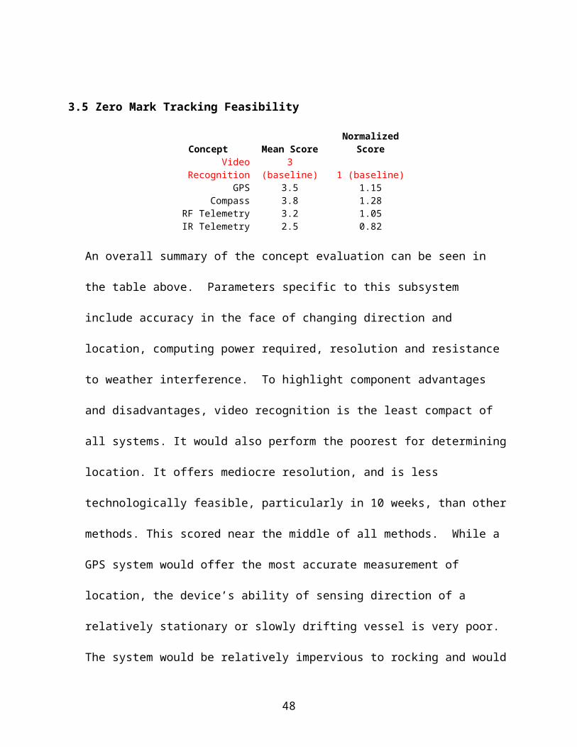
5.4.4 Microcontroller & Motor
The microcontroller must have the means to communicate with the remote’s relays, the
compass and the motor. Latched analog to digital converters are an ideal way to interface
with analog components. An I2C bus is the standard for interacting with intelligent
sensors. Digital outs to interact with a motor driver provide buffered protection when
controlling the motor. Accumulator style arithmetic and integrated real time clock
interrupts will facilitate development.
The Motorola HCS12 architecture provides such features. When implemented in an
Adapt9S12DP256, multiple forms of memory allow for permanent storage of the control
program.
The 50 in-oz motor used will, through gearing, will meet the torque requirement of one
in-oz to turn the camera (see Appendix L for torque calculations).
5.5 Control system
Feasibility testing indicates the use of the Crouzet Millenium II logic controller as the
primary control system for this project. Since a power supply is unavailable, the system must
run on 12-volt direct current, which will be supplied by a car battery. The group decided that
the controller should have surface-mount buttons to enter information directly into the
controller, effectively by-passing the remote control. It was also apparent that a liquid crystal
display screen is essential to aide in troubleshooting. Furthermore, the unit is required to have
at least six digital inputs to accommodate the RF receiver and electronic compass module.
The controller must also possess seven relay outputs to control the horn, three flags, and
camera drive motor. The Crouzet Millenium II SA20 Logic Controller meets these
specifications (a detailed specification sheet can be found in the Appendix M):
48

Millenium II SA20 12VDC Controller Specifications:
Part Number: 88950056Power Requirements: 12V DCInputs: 12 (discrete/analog/potentiometer)Outputs: 8 Solid State Relay
The low power consumption rate makes this controller ideal for the project. The controller
will be fed 12 volts direct current through its power input screw terminals. Each relay of the
RF receiver is given a dedicated discrete (digital) input. The electronic compass system
(controlled by a separate micro-controller) will use the Crouzet’s relays in a master/slave
relationship. Each of the relay output terminals will be connected to their respective solenoid.
It is important to note that the relay is a switch, which is located serially between the battery
and solenoid. Solid-state relays have no mechanical parts, and therefore, a longer lifetime
than traditional relays. Solid-state relays cannot handle large voltages or currents; this is,
however, a non-issue, as the system is low current and low voltage.
Software and hardware integration becomes simplistic with the Crouzet graphic
programming interface. The Crouzet programming software is controller specific, and
therefore will only work with Crouzet controllers. The program provides a simple
expandable workspace, with individual assigned spaces for inputs on the left, and outputs on
the right. A menu bar on top provides access to all of the pre-programmed function modules.
Every function block, input, and output is labeled at all pins for quick reference. Changing
the function of a component is a simple matter of double-clicking on the component and then
changing the parameters in the dialog boxes of the pop-up window. A sample program is
shown below in Figure 5.
49

Figure 5. Crouzet Programming Sample: Timing sequence of the class one flag
The program flow is straightforward. An input will be activated (either the start button on the
RF remote control, or the assigned start button on the controller itself), which will start the
show sequence. A series of timer blocks will activate the outputs (relays) at the appropriate
time periods. The program will contain the main show sequence, as well as an additional test
sequence, that will raise and lower each flag, sound the horn, and pan the camera in a short
time period. To accommodate the camera control system, the controller will have two analog
inputs connected directly to relay outputs (software connection). The camera control system
will use the controller’s relays as a slave system, without affecting the program or show
control in any manner.
5.6 System Housing
50

The system housing will be designed around the ACB components. For the components that
are sensitive to water, these portions of the system housing will be sealed. As an example,
the Camera will need to be contained in a sealed polycarbonate cage with wire glands used
for the electrical interfaces.
The pneumatics will be exposed to the outdoor elements; however, the enclosure limits the
amount of exposure. Since the cylinders are stainless steel and lubricated, there is little
concern of corrosion. For any exposed wiring terminals, RTV will be used to make these
junctions impervious to water.
5.7 Power Supply
One of the design goals of the ACB was to maintain power for a minimum
of 3 hours, or 180 minutes. As the ACB is remotely operated in a marine
environment, the atmospheric conditions play an important role in
selection of the power supply. In such an environment, there is concern
with corrosion and water ingress. In addition, the power supply must be
relatively light and portable. The team investigated a number of power
supply options including a gasoline-powered generator, solar power, and a
battery. Of these options, it was decided that a battery was the ideal
candidate because it is very portable, relatively lightweight, sealed to
prevent corrosion and water ingress, and long lasting.
5.7.1 Battery Selection
51

A variety of battery types were researched to determine the ideal
candidate for the requirements of the ACB. Specifically, starting, deep-
cycle, and marine batteries were investigated.
Starting batteries are most commonly used to start engines. They are
intended to supply a large starting current for a short period of time.
Starting batteries will generally fail after 30-150 cycles if operated
incorrectly (such as deep cycled), while they may last for thousands of
cycles in normal starting use (2-5% discharge per cycle).
Deep cycle batteries are designed to be discharged down as much as
50% each cycle. Although a battery may be labeled as “deep cycle,” it
may not be a true deep cycle battery. Unfortunately, it is often
impossible to tell whether or not a battery is truly deep cycle.
Regardless, this type of battery would be well suited to operate all the
components of the ACB for several hours.
Marine batteries are typically hybrid; falling between the starting and
deep-cycle batteries. Hybrid type batteries should not be discharged
more than 50% each cycle in order to preserve their lifespan.
After examining several possibilities, a 12VDC marine battery was selected for powering
the ACB components. Once the battery was selected, calculations were performed to
determine the life of the battery when subjected to the operating conditions of the ACB.
5.7.2 Electrical Load
52

To estimate power requirements of the entire ACB system, spec sheets
of each component requiring power were examined. A chart was
tabulated as shown in Figure 6.Device Number Voltage (V) Current (A) Power (W)12 VDC 3 12 0.0417 0.50043-Way Valve 1 12 1 12Compass 1 6 0.06 0.36Microcontroller 1 6 0.3 1.8Motor Driver 1 6 0.12 0.72VHS 1 6 1.5 9Crouzet 1 12 0.375 4.5Receiver 1 12 0.01 0.12Step down converter 1 12 1.57 18.84
Averages 9.3333 0.553 5.3156
Total: 4.977 47.840
Figure 6. Component Power Requirements
This table was calculated assuming a worst case operating scenario; each component will
continually draw peak current. The total system power and current requirements were
found to be 47.8 volts and 5.0 amps, respectively. These values were used to calculate
the life of the battery.
5.7.2.1 Battery Operating Life
The selected battery has an operating life rating of 115 Amp-
hours. Using a current draw of 5.0 amps, the battery life was
determined:
An operating life of 23 hours clearly exceeds the minimum
requirement of 180 minutes.
5.8 Analysis Conclusion
53

The system housing for the pneumatics and battery is shown below in Figure 7.
Cutaway View Enclosed ViewCutaway View Enclosed View
Figure 7. System Housing
Overall the subsystems will be assembled into the dinghy as shown below in Figure 8.
Figure 8. System Assembly
The team discussed the possibility of relocating the controller to the space over the battery.
This would simplify system set-up and removal. Additionally, the battery may be located in
the front of the vessel near the image recording and zero mark tracking system as these
54

components will require the most power. These minor details will be resolved
experimentally during Senior Design II.
6.0 Future Plans
To date, the team is on schedule and has completed the first five stages in the EDGETM
design process. A Gantt Chart (see Figure 9. below) was developed using Microsoft Project
to keep the team focused and organized during the remaining project phases.
Figure 9. Senior Design II Gantt Chart.
As shown above, the objectives and specifications as well as the analysis and synthesis
phases of the project are not completely finished. Progress was delayed as a result of
equipment difficulties and postponed sponsor meetings (due to the sponsor’s personal
obligations). The unresolved areas of the project are discussed in more detail in section 7.0,
Conclusions.
55

6.1 Experimentation
To verify that all of the project requirements and specifications have been met, the ACB
design team must complete several experiments.
First, the pneumatically driven flag raising system can be validated with a simple assembly
and test procedure. All components will be assembled as shown in the pneumatic and system
housing schematics (Figure 7). Then, the air reservoir will be pressurized to 115psi and the
system will be actuated until the reservoir is drained. The number of cycles will be noted and
compared to the specification of “several” cycles as well as to the calculated prediction of 33
cycles. Validation of the RF communication and timing sequence does not require that the
ACB system be set up in the vessel. These systems can simply be assembled and
experimentally tested in an appropriate workspace at RIT. The zero mark tracking system,
however, should be tested in the dinghy on Lake Ontario so that it is exposed to the vessel
roll and drift. Finally, the system housing can be tested by simply spraying it with a garden
hose and checking for water ingress, as per PYC requirements.
6.2 Budget
The total estimated budget for the Automatic Committee Boat design is show below (Figure
10) in the Bill of Materials. The total cost is predicted to be approximately $740.00, which
falls within the allotted budget of $800.00.
56
Subsystem Part name Part No. Vendor Qty Cost (each) Total costFlag Raising SMC Cylinder NCGDN40-0700 Kinequip 3 $0.00 $0.00
SMC valve SY3120-ULB980089 Kinequip 3 $0.00 $0.00clevis pin NCD-G04 Kinequip 3 $1.78 $5.34SMC wire SY100-30-4A-15 Kinequip 3 $1.94 $5.82
SMC 12VDC coil SY114-6LOZ Kinequip 3 $16.50 $49.50SMC valve manifold SS5Y3-40-04-N7T Kinequip 0 $31.11 $0.00
Filter/regulator NAW2000-N02-C Kinequip 1 $17.24 $17.24Gauge K40-MP1.0-N01S Kinequip 1 $4.04 $4.04
Relief valve 112C-2-150 Kinequip 0 $6.63 $0.003-Way valve VX3114-01N-6G Kinequip 1 $24.43 $24.43
1/4'' X 1/4'' elbow KQ2L07-35S Kinequip 0 $2.11 $0.001/4'' X 1/8'' elbow KQ2L07-34S Kinequip 10 $1.91 $19.10Street Tee 1/4'' 28-246 Kinequip 1 $1.48 $1.48
Air Tank 41855K25 Wal-Mart 1 $25.00 $25.00PVC (1/2-inch diam, 10' L) 23966 Lowe's 2 $1.29 $2.58
1/4'' tubing (100 ft) Kinequip 1 $16.75 $16.751/4'' steel rod N/A Metal Supermarkets 1 $0.00 $0.00
Rod mounting bracket N/A Metal Supermarkets 2 $0.00 $0.00$171.28 Subsystem Total
System Housing Wood 2'' X 4'' X 8' N/A A.D. Moyer 2 $0.00 $0.00Handles N/A A.D. Moyer 2 $0.00 $0.00hinges N/A A.D. Moyer 2 $0.00 $0.00
Wire glands N/A A.D. Moyer 5 $0.00 $0.00Rubbermaid container N/A A.D. Moyer 1 $0.00 $0.00
Polycarbonate N/A A.D. Moyer 1 $0.00 $0.00$0.00 Subysytem Total
ZM Tracking Compass R117-COMPASS AcroName 1 51 $51.00Microntroller Adapt9S12DP256 Technological Arts 1 99 $99.00Servomotor GM3 Hobby Engineering 1 5.5 $5.50Motor Driver L293D Hobby Engineering 1 12.5 $12.50
Turntable Target 1 19.99 $19.99$187.99 Subysytem Total
Image Recording VHS N/A PYC $0.00Camera Mounting
Control System Programming Cable 88950102 Dunn 0 53.1 $0.00Autocraft Marine Deep Cycle/RV24DC-2 Advanced Auto 1 64.88 $64.88Millenium II SA20 12V 88950055 Dunn 1 182.68 $182.68
$247.56 Subysytem TotalRemote Comm. 4-button handheld transmitterSK-919TP4H-N Christy Industries 1 $65.00 $65.00
4-channel receiver SK-910R4 Christy Industries 1 $75.00 $75.00educational discount - Christy Industries -$14.00
$126.00 Subysytem TotalGrand Total $732.83
ACB Bill of Materials
Donated
Figure 10. Planned Bill of Materials
7.0 Conclusion
The Automatic Committee Boat Project Team has, by and large, completed phases of design
including recognizing and quantifying the need, concept development, feasibility assessment,
design objectives and specifications, and analysis and synthesis of design. Following these
facets as outlined by EDGETM resulted in a comprehensive preliminary design package of the
57

proposed Automatic Committee Boat. However, there are still unresolved issues with the
camera motion control system and the donated VHS camcorder. In glare situations, the
recorded image becomes highly distorted as confirmed by outdoor field tests. Alternatives to
recording the race finish with the provided VHS include: an encoded clock (LED) displayed
on the vessel, a polarized lens for the camera, or a better quality camera. It should be noted
that the encoded clock was included in the feasibility assessment and was the highest scoring
concept (see Appendix E). This concept was chosen for use since PYC required an image of
the race finish. Additionally, more analysis and design is required for the gimbaled mount
and rotation mechanisms of the camera. Overall, the team must meet with the ACB project
sponsor to agree on a solution to these issues since there is not room in the budget to
purchase a polarized lens or a new video camera.
58

References
Moran, Michael J., Shapiro, Howard N. (2000). Fundamentals of EngineeringThermodynamics, 4th Ed. New York: John Wiley & Sons, Inc.
http://matweb.com/search/SpecificMaterial.asp?bassnum=O5601 Matweb.com – PVC properties
Bearing website – www.ntnamerica.com/Engineering/PDFs/2200/frictemp.pdf
SMC catalogs/website
PYC website
SD I class lectures -- EDGETM
Crouzet Manual http://www.crouzet-usa.com/catalog/millenium/MilleniumII_standard_US_A2.pdf
Fluids book
Interviews:
Kozak, Jeffrey. Personal interview. 1/31/05 and 2/3/05
Matteson, Eric. Personal Interview 2/8/05
Morris, Bill. Personal Interview 2/1/05
Nichols, Scott (see team minutes)
59

Appendix A - Signed Team Values and Norms Document
Team values and NormsAutomatic Committee Boat Project (#05510)
o All team members are expected to come to all meetings on timeo All team members are expected to check e-mail daily to ensure prompt responseso All team members must have “homework” assignments prepared for all meetingso All team members must respect each other and each other’s ideaso The team leader should keep the team organized and focusedo All team members should work on the project significantly outside of scheduled
meetings, as these meetings are mostly used to bring everyone up to speed on the progress of the project
o All team members should be willing to help each other and be understanding when someone has a busy day or two
o All team members must be willing to compromise – we will not all be satisfied 100% of the time, but we must move on for the interest of the group and project
o The team is expected to produce a professional, organized, and well-rehearsed presentation at the end of SD I and II
Signatures below indicate the team is in agreement to the above statements:
___________________ Cory Hoffman Date: ______________
___________________ Phillip Maskelony Date: ______________
___________________ Michael Moran Date: ______________
___________________ Vicki Parnell Date: ______________
___________________ Tristan Peterson Date: ______________
60

Appendix B - Signed Needs Assessment Document
Level 0,1,2 Needs Assessment
Level 0 – Project Mission Statement
The mission of the design project team is to design a modular automatic committee boat to replace a physical member of the Pultneyville Yacht Club in performing the race start sequence of flags and horns as well as to visually record the race finish.
Level 1 – Qualifiers
Performance: The automatic committee boat (ACB) shall be self-sustaining and self-operating with
input from a remote operator (this does not include anchoring and towing). The ACB shall run the race start sequence after it is triggered remotely by a PYC
member. The ACB shall have the capacity to repeat the race sequence several times. An ability to handle open water and prevent water ingress is critical. The ACB shall maintain onboard power for the duration of the race. A method of tracking sailboats and their finish times shall be implemented – this will be
accomplished by a video recording system as requested by PYC. The ACB shall be able to withstand outdoor weather conditions from May through
September in Rochester, NY. The ACB shall be portable and compatible with different types of vessels. A method of tracking the zero mark shall be implemented. Camera shall have the ability to view over the bow of the boat next to the video recorder. The recorded media shall be readily accessible. Test mode shall be implemented in design to ensure that all components are functioning
properly.
Schedule: The design shall be completed for implementation during the 2005 race year (summer). The robust design shall be useable with little to no maintenance for an entire racing
period (one summer). All major design process steps shall be communicated with the PYC steering committee
and scheduled appropriately. Meetings with program coordinator shall be held at least three to four times per quarter.
Technological: The ACB shall be remotely controlled. The ACB shall have onboard logistics capable of controlling several mechanized
systems. System power shall be sustained for the length of the race. A system for recording video of the race finish shall be included in the design.
61

A method of coordinating flag and sound signals through system logic shall be developed.
Economic: The ACB shall be designed and implemented within the budget of $800. Design shall utilize provided dinghy and or other designated vessel. Design shall not require modification of provided vessel (depreciation of vessel)
Level 2 – Winners
Performance: The ACB should complete the race start sequence of flags and horns The ACB should record race finish times (with time-stamped video) of individual
sailboats Data download should be quick System power should be maintained during race ACB should have a method of remote steering through harbor passages ACB should have a delay of race flag ACB should have a random start where the start sequence begins within the next two
minutes. A method of self-anchoring should be included. Inexpensive universal remotes should be used.
Schedule: The ACB should be completed and ready for use for the 2005 racing year The race starting sequence should be operated in the same timing fashion as the usual
PYC member who starts the race System start-up should be quick and allow sufficient time for the towing vessel to clear
and prepare for racing
Technological: ACB design should show no signs of water ingress ACB components should be corrosion resistant Damage or failure of operation should not occur due to rough water conditions Vessel stability should be maintained Race starting logic should be consistent and free of error. Remote control should be possible for a distance of up to 100 meters. The ACB should be self-anchoring ACB should be portable A warning beep should be implemented when a zero mark signal is not received. A beep for two seconds should sound when the finish line is blocked except for the first
four minutes after the race starts. A method of transmitting intermittent data to the shore should be included. Bilge pump operation should be controlled by the system.
62

63

Appendix C - PYC Requirments
Priority System Feature 1 - Required Starting Indicators Flags and audio indicators that the race is starting, Going through a set sequence of flags and audio indicators at designated timing intervals. R Flag slots for sequence and 2 fleets R Remote start/stop and reset of sequence R Air Horn - 3 second blasts R Subsytem is standalone portable for use on other vessals N Random delay start. - Start sequence begins within the next 2 minutes. W Delay of race flag 2 - Required Zero Tracking System that would be used to determine the relative direction to the zero mark and when the line was crossed Assumes some kind of beacon mounted on the zero mark. If using a video system to record line, then provides relative direction to video system R Zero mark can be up to 300 ft away. R Track zero mark +/- 30% of Cameras field of view at 300 ft R Can handle waves to 3 ft high without false alarms if giving crossing beeps N Warning Beep when not getting a Zero Mark signal N Beep for 2 seconds when line is blocked, accept for first 4 minutes after race starts 2 - Required Line Recording Video system that tracks on Zero mark and record races as they cross line. Captures video at least 1 frame per second, black and white image acceptable. Images are time stamped. Stamps accurate to <0.5 seconds after event. System follows the Zero mark per Zero tracking directions. R Shielding around Camera Lens for splash protection R Ability to see over Bow of boat adjacent to recorder R Quick access to recorded media Simple playback system Removable media or some kind of uplink, wireless preferred. Computer storage of images acceptable 3 - Nice Timing System Display Start Count Down and Count Up on control pannel Once the first race has begun, display an elapse time on control panel 4 - Nice Transmit Line recording to shore Use RF link to transmit periodic image to shore side recording station in club house. Distance about 1.5 miles. Use beacon light as relay station?? 5 - Wish Anchoring System to hold the dingy in place once it is on station near zero mark N Up & Down by remote control N Auto Up and Down - detects line tension and turns off system automatically W Alert when line is jammed - flashing light to indicate anchor system malfunction.
64

5 - Wish Tow LineSystem used to pull dinghy out to course area. Must allow for easy hookup and not interfere with anchoring system.
N Floating line with floats along lengthN Mechanism to pull line off to one side of boat, away from anchor. (preferably the left side)
6 - Wish In harbor maneuveringPropulsion and steering system that would allow leaving dinghy dock and moving over to tow vehicle. Simple control i.e. RC boat.
2 motors or 1 motor and steering
OTHER REQUIREMENTS
ControlsBox housing the controller and user interface for operating the system. Controller process remote control signals and sends control signals to subsystems.
R Dial for number of races, Continuous cycle, 1 race cycle to X cycles.
RTesting modes - Constant sequence cycle, start and run 10 minutes, quick test - cycle all flags on 10 second intervals, anchor up/down, Tracking system move
R Remote control of operation, anchoring, starting sequence.N Use cheap universal remotes, so that person that sets up does not have to bring in. (Need at least 3)R Remotes work from at least 100 ft away, preferably 300 ftR Gives acknowledging beep for commandsN Battery Level indicatorsN Air Pressure Level indicators
Other N Range measurement system for estimating line lengthR Flags, & horns can be run independent of dinghy and anchoring, line recording and zero tracking systems.R Collaspable for storageR Lockable R Splash and rain resistantR 12 volt car battery as power source. Charging system if need to get through seasonR Floation system for dinghy (PYC Issue)R Bilge Pump (PYC Issue)N Storage Canvas (PYC Issue)N Bumper Guards around perimeter of dinghy (PYC Issue)
Priority CodesR = RequiredN = Nice to haveW = Wish to have
65
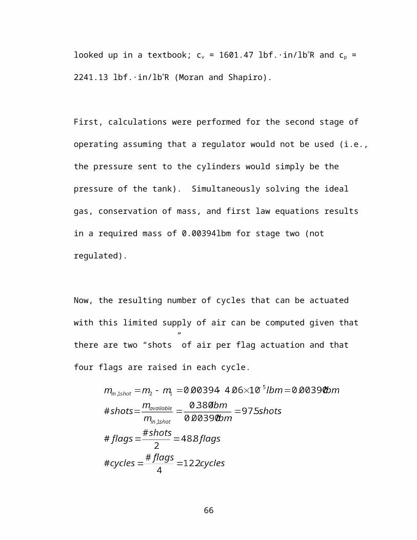
Appendix D - Concept Sketches
66

67

68

69
70
71

72

73

74

Appendix E – Feasibility Assessment
1 = Much worse than baseline2 = Worse than baseline3 = Same as baseline4 = Better than baseline5 = Much better than baseline
(1) S
prin
g an
d M
otor
- Bas
elin
e
(2) M
otor
and
Cou
nter
wei
ght
(3) C
ount
erw
eigh
t and
Pne
umat
ic C
ylin
der
(6) T
eles
copi
ng A
nten
na
(8) S
prin
g an
d M
otor
Typ
e II
(11)
Mot
or a
nd G
earin
g
(17)
Infla
tabl
e Fl
ag
Compact (fits within dinghy or smaller) 3 3 4 5 3 3 4Fast - raises quickly 3 3 5 2 3 2 2Inexpensive (Pref Less than $100 for System) 3 3 3 2 3 3 4Low Power Consumption (Can run on 12V) 3 3 4 3 3 3 4Technically Feasible 3 3 2 4 3 2 2Can Accomplish in less than 10 weeks 3 3 3 4 3 2 4Resistance to Water Ingress 3 3 4 4 3 3 4Robust/Reliable 3 3 5 3 3 3 3Not affected by severe winds or rocking motion 3 2 4 3 2 3 2Maintenance 3 3 2 3 3 3 2
Mean Score 3 2.9 3.6 3.3 2.9 2.7 3.1Normalized Score 1 0.97 1.20 1.10 0.97 0.90 1.03
Flag Raising Concepts (As Printed Numbered on 1/14/05 Document)
1 = Much worse than baseline2 = Worse than baseline3 = Same as baseline4 = Better than baseline5 = Much better than baseline
Des
ktop
Com
pute
r
Mic
roco
ntro
llers
Cro
uzet
Dev
ice
Boa
rd C
ompu
ter
Har
d W
ired
Har
d W
ired
Play
Bac
k
Compact (fits within dinghy or smaller) 3 4 4 4 4 2Inexpensive (Pref Less than $200 for System) 3 2 5 4 4 1Low Power Consumption (Can run on 12V) 3 4 4 4 5 3Technically Feasible 3 2 3 3 2 3Can Accomplish in less than 10 weeks 3 2 3 3 1 4Resistance to Water Ingress 3 4 4 4 4 2Robust/Reliable 3 3 4 3 5 4Not affected by severe winds or rocking motion 3 3 3 3 3 3Extensable 3 2 3 3 1 2Ease of Development Interface 3 2 4 3 1 3
Mean Score 3 2.8 3.7 3.4 3.0 2.7Normalized Score 1 0.93 1.23 1.13 1.00 0.90
Show Control Concepts
75

1 = Much worse than baseline2 = Worse than baseline3 = Same as baseline4 = Better than baseline5 = Much better than baseline
Dig
ital C
amer
a
VHS
Mot
ion
Det
ecte
d
RFI
D T
elem
etry
Clo
ck
Compact (fits within dinghy or smaller) 3 3 3 4 4Record Time 3 3 3 3 3Post-processing Time 3 3 4 4 5Inexpensive (Pref Less than $200 for System) 3 3 2 1 3Low Power Consumption (Can run on 12V) 3 3 3 3 4Technically Feasible 3 4 1 2 4Can Accomplish in less than 10 weeks 3 3 1 2 5Resistance to Water Ingress 3 3 3 4 4Robust/Reliable 3 2 3 2 4Not affected by severe winds or rocking motion 3 2 1 4 4"Cheatability" 3 3 3 3 1
Mean Score 3 2.9 2.5 2.9 3.7Normalized Score 1 0.97 0.82 0.97 1.24
Finish Recording Concepts
1 = Much worse than baseline2 = Worse than baseline3 = Same as baseline4 = Better than baseline5 = Much better than baseline
Vide
o - R
ecog
nitio
n
GPS
Com
pass
es
RF
Tele
met
ry
IR T
elem
etry
Compact (fits within dinghy or smaller) 3 4 4 4 4Accurate Location 3 5 4 4 3Accurate Direction 3 1 5 4 2Processing Power Needed 3 4 4 3 3Inexpensive (Pref Less than $200 for System) 3 2 4 3 4Low Power Consumption (Can run on 12V) 3 3 3 3 3Technically Feasible 3 4 4 3 3Can Accomplish in less than 10 weeks 3 4 4 3 3Resistance to Water Ingress 3 3 3 3 2Robust/Reliable 3 4 4 2 1Not affected by severe winds or rocking motion 3 4 3 2 1Resolution 3 4 3 3 2Other Weather Effects 3 3 5 4 1
Mean Score 3 3.5 3.8 3.2 2.5Normalized Score 1 1.15 1.28 1.05 0.82
Zero Line Concepts
76

1 = Much worse than baseline2 = Worse than baseline3 = Same as baseline4 = Better than baseline5 = Much better than baseline G
arag
e D
oor
IR R
emot
e
Talk
abou
t
Wi-F
i
Compact (fits within dinghy or smaller) 3 3 3 3Prone to Interference 3 1 2 2Inexpensive (Pref Less than $100 for System) 3 4 2 1Low Power Consumption (Can run on 12V) 3 3 2 2Technically Feasible 3 1 2 5Can Accomplish in less than 10 weeks 3 2 1 4Resistance to Water Ingress 3 2 3 3Robust/Reliable 3 1 2 2Not Affected by Sever Winds or Rocking Motion 3 2 3 3Prone to False Alarms 3 2 1 5Range 3 1 5 4Remote Price 3 3 4 1Remote Durability 3 3 4 1
Mean Score 3 2.2 2.6 2.8Normalized Score 1 0.72 0.87 0.92
Communication Concepts
77

Appendix F - Flag Pole Weight Calculation
Density of PVC ranged 0.0462 to 0.0564 lb/in3, as per matweb.comTherefore, let density of PVC = 0.05lb/in3
Given:OD = 0.54 inchesID = 0.3 inchesρ = 0.05 lb/in3
78

Appendix G -Working Model Supporting Calculations
When flag is in raised position:
Worst case scenario to raise flag:
When flag is in raised position:
For resulting max wind velocity that system can withstand:
Appendix H - Air Supply Calculations
79
θh 7’’
5’’

In order to treat air as an ideal gas, the following must be true: and
From the Thermo text book, the following critical values of temperature and pressure were found for air:
and
Now, assuming a worst case scenario operating temperature of 40F (499.7R) and a maximum operating pressure of 125psig:
Thus, treating air as an ideal gas, the initial mass of air in the 5 gallon tank can be calculated:
From Working Model, Force required to raise flag is 18.5lb. Area of selected cylinder is 1.94 in2. Therefore, the minimum pressure (of the tank) required to raise one flag is:
Now the mass of the tank’s residual air can be calculated:
80

Now the total amount of available air can be calculated:
In the first stage of operation (before the cylinder has expanded), the initial mass of air in the pneumatic lines, valves, and cylinder must be calculated. Note that these values are being calculated for the actuation of only one cylinder. The following assumptions were made:
The mass of air in the valves is negligible. The initial mass of air in the cylinder is negligible since the bottom of the piston was
assumed to be in direct contact with the housing.Using these assumptions, the following was determined:
In the second stage of operation, the cylinder is fully actuated. First, it was assumed that a regulator would not be used (i.e., the pressure sent to the cylinders would simply be the pressure of the tank).
Now, conservation of mass and the first law must be used:
Conservation of mass: First Law:
Since cv and cp change very little over a temperature range of 40F to 90F, it can be assumed that cv and cp are constant at room temperature. Looking these values up in the Thermo book and converting results in:
81

Simultaneously solving the system of equations results in:
Now, the resulting number of cycles that can be actuated with this limited supply of air can be computed as follows:
82

Now, the problem is recalculated with the use of a regulator. The previous calculations will remain the same up until the second stage of operation where the cylinder is fully actuated. To decide how much air pressure would be released by the regulator to the cylinders, the following calculations were performed:
From Working Model:
Using a Factor of Safety of 2,
Therfore:
83

Now, the resulting number of cycles that can be actuated with this limited supply of air can be computed as follows:
84
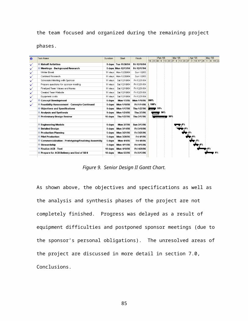
Appendix I - Stress Calculations
Bending for flag support rod:
Shear Diagram:
85
2lbs 2lbs2lbs6lbs Diam. = 0.25in
RBRA
V
-3lbs
3lbs
5in
10in

Stress in PVC Flagpole:
When flag is in raised position:
Cross-Sectional Area:
Max Allowable Load:
86
θ
5lbs
mg
Stress raiser, diameter = 0.25in
0.5in
Flag Pole Schematic
Approximate area deleted by holes =2*0.1in*0.25in=0.05in2

Flagpole Bending:
87
Fdrag ,max = 2.14lbs
13 lbsRA
10.86 lbs
5inV
7.5in
x

Appendix J - Camera Field of View Calculations
50 feet
100 feet of anchor line
ACB
82.3’
100’50’
2 2100 50 7500
7500 86.6 ft
Accounting for 5% line slack:
86.6 95% 82.3 ft
88
Note: 5 foot buoy radius is assumed.
Worst case scenario for FOV is 2*(82.3+5)=174.6’

Appendix K - Zero Mark Tracking Geometry
89

Appendix L - Torque to Turn VHS Table
Source: www.ntnamerica.com/Engineering/PDFs/2200/frictemp.pdf
90

Appendix M - Crouzet Specifications Manual
91

92

93

Appendix N – Senior Design I Gantt
94