Embed Size (px)
Citation preview

Design and Fabrication of a Miniature Tensile Load frame for a
Scanning Electron Microscope
Senior Design Team 04-004
Critical Design Report
May 14, 2004
Robert Rinefierd – Team Manager, Mechanical Engineer Evan Kastner – Lead Engineer, Mechanical Engineer
Nicholas Currier – Mechanical Engineer Blaine Stuart – Mechanical Engineer
Kennedy Mogwai – Industrial Engineer Evan Brunner – Computer Engineer

Executive Summary
The tensile load frame is part of a series of projects funded by the Mechanical
Engineering Department to construct specialized lab equipment. The purpose of this
project was to design and construct a load frame for the scanning electron microscope
(SEM) in the CIMS Materials Science Lab. Mechanical Engineering faculty and students
will use the machine for research of metallographic structures during tensile testing.
Most tensile load frames will not fit within a small vacuum chamber, which makes this
design unique. In addition, most microscopes will not allow for dynamic analysis of
bonds, welds, or other areas of interest during a tensile test.
In addition to fitting inside the narrow packaging envelope in the vacuum
chamber, the load frame must operate safely in a vacuum environment. Many
mechanical constraints of the chamber limit the usable space to an envelope of 10 inches
long, 9 inches wide, and 3 inches high. All components must be vacuum-rated to avoid
contamination and outgassing. Also limiting the design is a maximum cost of $7,500.
Several concepts were evaluated, including a design using two power screws and
a motor inside the vacuum chamber, a hand driven design with a removable crank, a
design using a single driving screw and an internal motor, and a two screw design with a
motor mounted externally to the chamber. The two-screw design with an internal motor
was the recommendation from feasibility assessments and the design was developed.
The test samples will be standard ASTM cylindrical geometry with threaded ends.
Loads will range from 200 lb in compression to 2000 lb in tension. After calculating the
torque required to raise the tension to 2000 lb from a static condition, motors, gearboxes,
and drivetrain components were researched to create a mechanism to apply the necessary
torque to the power screws. The design utilized a mounting point on the existing SEM
position fixture, necessitating a cantilever design, where the two power screws support
the free crosshead.
The driving source is a stepper motor using a controller with load feedback and a
position estimate. Load and position data will be recorded in LabView and a user
interface will be designed to run the load frame from a laptop computer. The design was
analyzed with finite element modeling for stress and deflection before production began.
A functional prototype was built without any major problems.
ii

Table of Contents
1 Recognize and Quantify the Need .............................................................................. 1
1.1 Project Mission Statement........................................................................................................... 1
1.2 Product Description .................................................................................................................... 1
1.3 Scope Limitations ........................................................................................................................ 2
1.4 Stakeholders ................................................................................................................................ 2
1.5 Key Business Goals ..................................................................................................................... 2
1.6 Financial Analysis ....................................................................................................................... 3
1.7 Preliminary Market ..................................................................................................................... 3
1.8 Secondary Markets ...................................................................................................................... 3
1.9 Order Qualifiers .......................................................................................................................... 3
1.10 Order Winners............................................................................................................................. 4
1.11 Innovation Opportunities............................................................................................................. 4
1.12 Background Research.................................................................................................................. 4 1.12.1 Describe the Need.............................................................................................................. 4 1.12.2 Categorize the Need........................................................................................................... 4 1.12.3 Constraints ......................................................................................................................... 5 1.12.4 Existing Products ............................................................................................................... 5
2 Concept Development................................................................................................. 7
2.1 Overview of Tensile Testing Equipment ...................................................................................... 7
2.2 Integrating the Product with the Current Fixture ....................................................................... 9
2.3 Concept Design Proposals ........................................................................................................ 11
2.4 Concept 1 – Internal Motor with Two Driving Screws.............................................................. 14 2.4.1 Concept Overview ................................................................................................................ 14 2.4.2 Design Features .................................................................................................................... 14 2.4.3 Preliminary Bill of Materials ................................................................................................ 15
2.5 Concept 2 – Internal Motor with Single Driving Screw ............................................................ 17 2.5.1 Concept Overview ................................................................................................................ 17 2.5.2 Design Features .................................................................................................................... 17
iii

2.5.3 Preliminary Bill of Materials ................................................................................................ 18
2.6 Concept 3 – Manually Driven Load Frame............................................................................... 21 2.6.1 Concept Overview ................................................................................................................ 21 2.6.2 Design Features .................................................................................................................... 21 2.6.3 Preliminary Bill of Materials ................................................................................................ 22
2.7 Concept 4 - External Motor with Two Driving Screws ............................................................. 24 2.7.1 Concept Overview ................................................................................................................ 24 2.7.2 Design Features .................................................................................................................... 24 2.7.3 Preliminary Bill of Materials ................................................................................................ 25
3 Feasibility Assessment.............................................................................................. 26
3.1 Introduction............................................................................................................................... 26
3.2 Evaluation of design concepts ................................................................................................... 26
3.3 Pugh Evaluation ........................................................................................................................ 27
3.4 Weighted Concept Evaluation ................................................................................................... 27
3.5 Results ....................................................................................................................................... 29
3.6 Conclusion................................................................................................................................. 32
4 Objectives and Specifications ................................................................................... 33
4.1 Design Objectives...................................................................................................................... 33
4.2 Performance Specifications....................................................................................................... 33
4.3 Design Specifications/Implementation ...................................................................................... 34
4.4 Evaluation Criteria.................................................................................................................... 34
4.5 Safety Standards ........................................................................................................................ 35
5 Analysis and Synthesis ............................................................................................. 36
5.1 Design Structure Matrix (DSM) ................................................................................................ 36 5.1.1 Introduction .......................................................................................................................... 36 5.1.2 Problem Statement................................................................................................................ 36 5.1.3 Results analysis..................................................................................................................... 36
5.2 Motor and Gearbox Selection ................................................................................................... 37
5.3 Drivetrain Design...................................................................................................................... 39
iv

5.4 Gripping Mechanism................................................................................................................. 41 5.4.1 Specifications of the Grips.................................................................................................... 41 5.4.2 Purchased or Machined?....................................................................................................... 42 5.4.3 Final Design of Grips ........................................................................................................... 42
5.5 Base and Frame......................................................................................................................... 43
5.6 Control and Display .................................................................................................................. 44 5.6.1 Beginning Estimates ............................................................................................................. 44 5.6.2 Control response constraints................................................................................................. 45 5.6.3 Sample Response Characterization....................................................................................... 45 5.6.4 Hardware Design Fundamentals........................................................................................... 47 5.6.5 Control Software................................................................................................................... 49
5.7 Vacuum Interface ...................................................................................................................... 51
5.8 Stress Calculations for Critical Components ............................................................................ 51
6 Preliminary Design ................................................................................................... 53
6.1 Part Numbers for Pro Engineer files......................................................................................... 53
7 Engineering Models .................................................................................................. 54
7.1 Part and Assembly Modeling..................................................................................................... 54 7.1.1 Modeling with Pro/Engineer................................................................................................. 54 7.1.2 Finite Element Analysis with Pro/Mechanica and I-Deas .................................................... 55
7.2 Testing the Product for Reliability and Quality ........................................................................ 61 7.2.1 Integrated Test Plan for SEM Load Frame ........................................................................... 61 7.2.2 Individual Test Plans ............................................................................................................ 62 7.2.3 Component Processing ......................................................................................................... 63 7.2.4 Subassembly Testing ............................................................................................................ 63 7.2.5 Deployment Testing ............................................................................................................. 64
8 Final Design .............................................................................................................. 65
8.1 Changes from Preliminary Design ............................................................................................ 65 8.1.1 Gripping................................................................................................................................ 65 8.1.2 Shaft and Bearing Setup ....................................................................................................... 66 8.1.3 Free End and ACME Nuts.................................................................................................... 67 8.1.4 Custom Gear Design............................................................................................................. 67
8.2 Cost Analysis ............................................................................................................................. 68
v

8.3 Design for Manufacture ............................................................................................................ 69 8.3.1 Introduction .......................................................................................................................... 69 8.3.2 Design Phase ........................................................................................................................ 70 8.3.3 Design Optimization............................................................................................................. 71 8.3.4 Results .................................................................................................................................. 71 8.3.5 Suggestions for Redesign ..................................................................................................... 72
8.4 Included Parts ........................................................................................................................... 72
9 Production Planning.................................................................................................. 75
9.1 Material Considerations............................................................................................................ 75
9.2 Tooling Design and Machine Setup........................................................................................... 76
9.3 Manufacturing Process Sheets .................................................................................................. 77
10 Pilot Production .................................................................................................... 79
10.1 Manufacturing Difficulties ........................................................................................................ 79
10.2 Assembly Design........................................................................................................................ 80
10.3 Manufacturing Pictures............................................................................................................. 80
10.4 Recommendations for Improvement .......................................................................................... 83
References......................................................................................................................... 85
Appendix........................................................................................................................... 86
vi

1 Recognize and Quantify the Need 1.1 Project Mission Statement
The mission of this senior design team is to design and construct a tensile load
frame for the scanning electron microscope (SEM) in the CIMS Materials Science Lab.
The tensile stage must be lightweight, affordable, and easy to carry.
1.2 Product Description A scanning electron microscope (SEM) allows for high-powered magnification of
the surface or near-surface structure of specimens. Images are produced when a beam of
electrons is reflected off of the sample surface. A detector monitors the radiation and the
electrons scattered by the surface. Scattered energy and electrons form a surface profile,
which is mapped to a cathode ray tube and the image is formed. Apertures and magnets
act to focus the beam in much the same way that a lens would. However, the image is
not controlled by lenses, amplified only by changing the size of the raster, the area
scanned by the electron beam. Scanning electron microscopes are capable of much
higher levels of magnification than ordinary light microscopes, reaching magnifications
of 25,000X. In comparison, a typical light microscope may reach a maximum
magnification of 2000X. The most important characteristic of a scanning electron
microscope is that it has a large depth of field, allowing the image to stay in focus across
a rough surface. This is why the machine is ideal for examining fracture surfaces.
Currently, samples may only be evaluated without a load in the CIMS scanning
electron microscope. The surface analysis can only be performed on a sample before or
after testing. A load frame would allow the surface behavior of a sample to be monitored
under tensile loads. Distortion and elongation can be monitored dynamically on a
microscopic level while a tensile load is being applied. Applications for this project
would be to monitor local stress fields in welds, bond sites, or high stress areas. The
tensile stage is to be designed specifically for the SEM used in the CIMS Materials
Science Lab. Though opportunities may exist for incorporating product features into
future designs in industry, the product will be a single unit with no plans for mass
production.
1

1.3 Scope Limitations The tensile stage must be designed and manufactured within 22 weeks of the
winter and spring quarters 2003-04. Sponsor Dr. Elizabeth DeBartolo will own the
tensile stage upon completion and it will be stored in the Mechanical Engineering
Department’s facilities. The National Center for Remanufacturing and Resource
Recovery (NCR³), owner of the SEM in the CIMS Materials Science Lab, has no current
interest in the product and will not be using it. Therefore, the product will need to be
transported easily to the CIMS building from the Engineering building.
The microscope has a position fixture, which is adjustable along the X, Y, and Z-
axis, tilt, and rotation. A load frame would need to be positioned to scan the desired area,
necessitating a positioning mechanism. Due to the logistics of replacing the existing
setup and the expense of building an additional module, the design will use as much of
the existing fixture as possible. It is not feasible to construct a new position fixture and
incorporate it with the load frame and is therefore beyond the scope of the project.
1.4 Stakeholders Major stakeholders in the project are Dr. DeBartolo and faculty members of the
Mechanical Engineering Department who may be performing materials research.
Additional stakeholders would include any thesis students or undergraduate students who
wish to perform advanced materials research with a scanning electron microscope.
1.5 Key Business Goals This project is part of a series of projects funded by the Mechanical Engineering
Department, the goal of which is the design and construction of lab equipment for use by
mechanical engineering students and faculty. With financial constraints limiting the
ability to purchase new equipment, some highly specialized equipment that may not be
widely used will be designed and constructed with funding from the Mechanical
Engineering Department. Ultimately, the goal is to design for the production of one load
frame. If the design is innovative and successful, it may be presented at an ASTM
conference in the spring with other student designs. A possibility exists to market the
design to various manufacturers at such conferences, but this is not a requirement.
2

1.6 Financial Analysis Dr. Hensel and Dr. DeBartolo, the faculty coordinator and faculty mentor,
respectively, approved a budget of $7,500 for design and construction of the load frame.
In addition to the purchased components, raw material cost is the only other major
expense. Use of the College of Engineering machine shop is free and manufacturing time
is not a monetary expense. Also, the necessary software packages (Pro Engineer and
ANSYS) are already available in the Mechanical Engineering labs, so no software costs
exist.
1.7 Preliminary Market As the project is funded by the Department of Mechanical Engineering, the
preliminary markets for this product are the students and faculty of the department who
may be performing metallographic research with the SEM in the CIMS Materials Science
Lab. The market will be very selective, as all users shall obtain permission from the lab
supervisor in CIMS as well as a faculty advisor before using the machine.
1.8 Secondary Markets The secondary markets for this product are students of other disciplines of
engineering and possibly their faculty. In addition, manufacturers of mechanical testing
equipment may be approached with the results of this project. Though they currently
have no interest in the product, engineers in the CIMS NCR³ Materials Science Lab may
find applications for it if a successful product is developed. This module may lead to
new NCR³ research projects involving the SEM.
1.9 Order Qualifiers The product shall be modular, easy to install, and lightweight. It should be simple
to manufacture, consisting of components that can be machined and assembled during
spring quarter. It shall have at least one working set of grips to accommodate either flat
or cylindrical specimens. Most importantly, it will have a position and load display,
allowing the samples to reach the correct tensile loads. The machine will meet the
sponsor’s minimum load capacity of 1000 lb.
3

1.10 Order Winners The frame shall fit inside the SEM chamber; this distinguishes it from the
standard laboratory load frames. Most importantly, the load frame shall not interfere
with the functionality of the SEM, allowing for dynamic analysis of a sample in tension.
Tension can be adjusted while the chamber is at vacuum pressure, so multiple images
may be created at varying tensile loads. It will accommodate loads ranging from 2000 lb
in tension to 200 lb in compression.
1.11 Innovation Opportunities Though this is a single product not intended for major production or design
improvements, some innovation opportunities exist. The possibility exists for using
interchangeable grips. The use of threaded grips, v-grips, and flat grips would
accommodate almost any test sample that fits within the SEM chamber and load frame.
Cylindrical and rectangular samples could be analyzed. Design ideas may also be
marketed at an ASTM conference in the spring. Future senior design projects could
adapt the product for high temperature testing and testing microscale structures. Other
projects might involve the design of a tensile fatigue load frame roughly based on the
tensile frame developed in the project.
1.12 Background Research 1.12.1 Describe the Need
A description of the customer’s needs was prepared using sketches and various
written ideas. The manager’s ideas were compared with the customer’s needs. In the
span of three initial meetings, the customer provided feedback and contributed additional
ideas towards the Needs Assessment.
1.12.2 Categorize the Need
Category 4. New Problem, No Process or Product.
The SEM currently analyzes samples with no loading. Though reasonable
observations may be made with no applied load, much can be learned about the material
by its dynamic behavior under various tensile loads. RIT does not own a product capable
of applying tensile or compressive loads within the microscope’s vacuum chamber.
Relatively recent technology led to the development of other SEM tensile stages and only
a few designs currently exist. Though a load frame might be available for purchase, the
4

cost would be prohibitive. As a result, the project will allow for the design and
development of a cheaper customized product to meet the research needs of the customer.
1.12.3 Constraints
The major constraints of the design process are the size limitation, material cost,
time for design and development, and time for manufacture. The fixture must fit within
the vacuum chamber and any electrical or mechanical connection must be properly
sealed. Port doors are replaceable with custom doors or windows and the seal must be
strong enough to withstand the vacuum pressure. The load frame must stay within an
envelope 3” high, 9” wide, and 10” deep. Components may extend outside the chamber
if the protruding parts are properly sealed. Most importantly, the components should be
free of any oils and materials should be safe in a vacuum environment. Special vacuum-
safe lubricants are available.
As the fixture is intended for the private non-commercial use of students and
faculty, it will not have any applicable industry standards or regulatory agencies to
govern the design, installation, or service of the product. However, it will meet the
approval of the SEM owner before installation. The product is a single unit of
production, customized for the microscope and position fixture in the CIMS Materials
Science Lab and will not be sold. Market prices are not important, but cost must be kept
within the allotted budget. The design is therefore not under as many constraints as a
marketed product, and it is a new problem. Though no product exists for this
microscope, designs may be based on similar existing products.
1.12.4 Existing Products
Two existing products were identified which provided some ideas for the design.
The design created by Lehigh University (Figure 1.1) was not patented, but a detailed
photograph allowed for analysis of the drivetrain setup and provided the team with an
idea with which to begin the design process [1]. It was the basis for the idea of a two-
screw motor-driven design. The design employs two power screws with spur gears on
the ends of each screw. A position sensor and load sensor are included. A motor and
gearbox combination drives the system. A series of gear reductions occur with the help
of a worm/worm gear pair and some spur gears.
5

The other product was a US patent [2] and was not as helpful in creating the
design. In both cases, the budgets seemed to be considerably higher than that of this
team, so only the basic layout and some machine functions could be adopted into this
design. However, this discovery confirmed that such a fixture could be designed and
built.
Dr. David Davidson of the Southwest Research Institute in San Antonio is one of
the few individuals to design and build such a load frame. He has designed machines for
fatigue testing applications within a scanning electron microscope [3]. His designs were
too expensive and too complex to integrate into the development of this project.
Individuals such as Dr. Davidson usually design these miniature load frames instead of
large companies because each machine is a custom design.
Figure 1.1 - Lehigh University concept
6

2 Concept Development Initial concepts were designed after a period of research, capturing a wide variety
of ideas from all team members. Beginning with background research on existing tensile
testing equipment, the design team reviewed existing full-scale load frames. Full-scale
machines provided the team with ideas for the initial concept designs. Brainstorming
sessions were performed for the more serious design concerns, including the integration
of the load frame into the existing scanning electron microscope and determining a basic
setup for the electronic control system. A series of team proposals was made for various
combinations of modules and for a general machine layout. The top four proposals were
developed with detailed concept sketches, a short report, a preliminary bill of materials,
and a preliminary cost analysis. Team members reviewed each concept proposal and
contributed ideas towards the robust development of each design in preparation for the
feasibility assessment.
2.1 Overview of Tensile Testing Equipment Uniaxial tensile testing is one of the most frequently performed mechanical tests.
On a full-scale machine, this type of test generally involves gripping a specimen at both
ends and subjecting it to an increasing axial load until it fractures. Collection of load and
elongation data during the test allows the operator to determine several characteristics
about the mechanical behavior of the material, such as strength and stiffness. Tensile
testing equipment consists of several types of devices that apply a controlled tensile load
to test specimens. The equipment is capable of varying the rate of load and accurately
measuring the forces, strains, and elongations applied to the specimen.
Equipment has evolved from purely mechanical or electromechanical machines to
sophisticated instruments that employ advanced electronics and microcomputers [4]. The
current technology of tensile testing equipment primarily consist of the force application,
moving crosshead, gripping mechanism, fixed base, control and display panels (Figure
2.1).
The load frame for this project was designed to fit and function within the
chamber of a scanning electron microscope (SEM), allowing for microstructure analysis
during tensile tests. Full-scale load frames would not fit within a microscope chamber.
This machine will allow analysis of microstructures during the tensile tests. The load
7

frame is scaled-down, but will still include some of the technological advances of a
modern tensile load frame.
Figure2.1 – Diagram of Tensile Testing Equipment
Tensile Testing
Equipment
ElectromechanicalServo hydraulic
Driving
screwsCrosshead
Gripping
Method
Fixed
Base
High-Torque
Motors
Control &
Display
2 Screws 4 ScrewsScrew
Action
Wedge
Type
Button
head
Pneumatic
Action
8

2.2 Integrating the Product with the Current Fixture Some of the most critical and difficult design decisions involved the incorporation
of the load frame within the existing microscope chamber. The scope of the project does
not involve designing a position fixture with the load frame, and as a result, the load
frame must be designed to fit the constraints of the existing position fixture. Early in the
concept development process, a brainstorming session identified most of the potential
problems that must be overcome to integrate the load frame into the existing SEM. The
twenty problems are listed in Table 2.1. Each group member placed four votes for the
problems that they deemed the most important to overcome. The important issues
identified were: maintaining a vacuum seal for wires and/or components that may pass
through the chamber, the size and location constraints of the chamber, the ability to
control the applied force and position, and the portability of the module. Though not
identified as an initial concern, cost grew in importance as research progressed on grips,
motors, and other purchased components. Also growing in importance was the vacuum
rating of all components.
9

Table 2.1 Brainstorming results for development problems. Problems that must be overcome to integrate load stage with SEM Votes Rank
Maintaining vacuum seal / sealing methods 5 1
Size and location constraints of the chamber 5 1
Ease of assembly 0 NR
Grounding of sample (electrically) 2 5
Ease of installation 0 NR
Removing part of existing fixture / disconnecting wires 0 NR
Don’t interfere with electron gun 0 NR
No electrical interference 0 NR
Meets approval of machine owner (Mike H.) 1 6
Displaying load 0 NR
Portable 3 3
Lightweight 0 NR
Control of applied force and position 3 3
Control of grips 0 NR
Wire interface through door 0 NR
Cleanliness / no oil or impurities 0 NR
Securing load frame 1 6
Mechanical losses in motor 0 NR
Cost limit ~ $7,500 0 NR
Vacuum rating of components 0 NR
Distribution of load evenly in samples 0 NR
Since the team is composed of four mechanical engineers, one industrial engineer
and one computer engineer, incorporating an electrical control system was a major
challenge for the team. In order to further analyze the interaction of the tension control
system, an empathy session was performed. One student performed the role of the power
screws, while another performed the role of the motor. A third student performed the
role of the grips, a fourth acted as the control/display module, and a fifth performed the
10
role of the test sample. An operator (not portrayed) places the sample inside of the grips
and tightens them manually. Once the sample is sufficiently tight, the operator turns a
dial on the control box to apply the tension. The control box sends a signal to the motor
to rotate at a specified torque based on the desired tension. The motor needs a drivetrain
(not portrayed) to interact with the screws. As the screws turn, the sample gradually
stretches. A load cell (not portrayed) is needed to transmit force data and a position
sensor (not portrayed) is needed for transmitting position data to the controller. When the
sample reaches its specified tension, the control box needs to cut the power on the motor
and lock position at the desired tension. The screws are self-locking and hold the sample
at the desired tension. Simply cutting the power to the motor is a sufficient solution.
Several issues presented themselves during the empathy session. One major issue
was supplying power to the motor and controls. Also, if the control box needs to interact
with the motor in addition to load and position sensors, the module must be customized
and have some programming functionality. The module may have to interpret signals
and convert them to a desired output. In order to prevent sample slipping, the grips
should be threaded, knurled, or grooved. The screws should not elongate or deflect in
bending. Fine pitch screws would provide the best position control and minimize
backlash. Most importantly, the motor’s torque output should be sufficiently high to
avoid stalling, a problem with potentially disastrous results when a load is applied.
2.3 Concept Design Proposals The initial concept design proposals involved various load frames based around
the same concept with different features. Four design choices were made for each design,
as the machine already had several constraints and would not allow radically different
concepts. Grip types were varied, including screw-driven, self-locking wedge grips, and
motor driven. Motors were varied between stepper motors and torque motors. The
support structure was either sliding or cantilever. The cantilever would have a fixed grip
and a moving grip that is supported only by the driving screws. A sliding support would
have a plate with runners to support the moving grip. Screws, gears, and belts were
considered as drivetrain options. Each group member had a maximum of four votes, but
did not have to use all of them.
11

Table 2.2 - Initial Concept Proposals Grip Type Motor Type Support Drivetrain Votes Rank
1 Screw grips Torque motor Sliding base Screws/gears 5 1
2 Screw grips Stepper motor Sliding base Screws/gears 1
3 Self locking Torque motor Sliding base Screws/gears 3 2
4 Motor grips Torque motor Cantilever
base
Gears/shafts 0
5 Motor grips Torque motor Cantilever
base
Screws/gears 1
6 Motor grips Torque motor Sliding base Screws/gears 2 3
7 Screw grips Torque motor Cantilever
base
Screws/gears 2 3
8 Screw grips Torque motor Sliding base Gears/shafts 1
9 Motor grips Torque motor Cantilever
base
Gears/shafts 1
10 Self locking Torque motor Sliding base Belts 0
11 Self locking Stepper motor Sliding base Gears/shafts 1
12 Motor grips Stepper motor Sliding base Gears/shafts 0
13 Motor grips Stepper motor Sliding base Screws/gears 0
14 Screw grips Torque motor Sliding base Belts 0
15 Screw grips Torque motor Sliding base Hydraulics 0
The initial brainstorming session led to several design choices. Belts and
hydraulics would not be considered as options for the drivetrain. Hydraulics would not
be feasible because of the vacuum pressure and possible leakage of hydraulic fluid. In
addition, the price of a hydraulic system would be prohibitive. Due to the small size of
the system, belts and pulleys would not achieve the necessary speed reduction. A good
gearbox should be sufficient to achieve the necessary speed reduction from the motor to
the screws. The top four concepts had many similar features. Distinguishing between a
design decision and a completely different concept design was difficult. Purchased
components, such as the motor, gearbox, grips, and load cell dramatically increase cost.
12

Choices must be finalized after various concept proposals incorporate the components in
different configurations. As a result, the group proposed a new set of designs. The set of
concepts was more general and focused on the creation of a generic load frame varying
the style and location of the drivetrain.
Table 2.3 - Final Concept Development Proposals Concept Description Votes Rank
1 2 driving screws with internal motor and gearbox 5 1
2 1 driving screw with internal motor and gearbox 5 1
3 2 driving screws with mechanical hand crank/gearbox 5 1
4 2 driving screws with an external motor/gearbox 4 1
5 1 drive screw with an external motor/gearbox 0 NR
6 4 drive screws with an internal motor/gearbox 0 NR
7 4 drive screws with an external motor/gearbox 0 NR
8 2 drive screws with motor and no gearbox 1 5
Concepts 1-4 were chosen for development and analysis in further detail.
Concept development studies focused on a concept overview, design features, a
preliminary bill of materials and some initial assembly sketches to work out the basic
logistics of the design and obtain a cost estimate.
13

2.4 Concept 1 – Internal Motor with Two Driving Screws 2.4.1 Concept Overview
Concept 1 is an internal motor driven, two-screw, cantilever load frame contained
within the vacuum chamber of the SEM. The main features of this concept are screw-
tightened grips, a gearbox to screw drivetrain powered by a stepper motor, and a
cantilever mounting setup. The specific type of motor to be used and the method through
which it is controlled was a topic of discussion through the preliminary design stages. As
long as the grips are light and the power screws are of sufficient size, deflection shouldn’t
be an issue with this design. All fabricated parts within the SEM will be machined from
AISI stainless steel (303 or 304). If the screws bend too much, loading would not be pure
axial tension and load readings would not be accurate. The weight of the support on the
fixed end should be fairly small, as the gearbox weighs less than 2 pounds. Grips could
be purchased, but another cost-reduction option is a custom set of grips to fit the exact
specifications of the chamber. As a result, weight and size are minimized.
2.4.2 Design Features
On the fixed end, the gearbox and one grip will be fastened to an L-shaped
support. The support will be stiff, strong, and corrosion resistant. The two power screws
will support the free end and drive it by applying tension or adjusting position before
gripping. As stated above, stainless steel was the material of choice for the screws and
both grip supports because of its strength and corrosion resistance in the vacuum
environment. All machined surfaces must be free of any cutting oils and contaminants
before installation to avoid contamination of the vacuum chamber.
Turning a screw on the jaw modules will loosen and tighten grips. Ideally, grips
will be purchased from Tinius Olsen, MTT, Instron, or another leading competitor. The
cost of a vacuum rated motor and gearbox, vacuum-sealed electrical feed-through, not to
mention the load cell, leave very little capital for grips, and fabricating a set that will
work to perfection in a laboratory is cause for concern. Tinius Olsen has set a current
standard with a set of grips that meet the design requirements, although a slightly larger
than preferred, for $2000. Instron may be able to provide a set of smaller remanufactured
grips for considerably less money. The grips will have a wedge mechanism, moving the
14

jaws closer together as a screw is tightened. The fixed grip will incorporate a load cell to
measure tensile force in the sample.
A small display box will incorporate a live display for tension and position.
Position display will be absolute and of mostly cosmetic benefit, however, the extremes
of travel will be entered into the control logic to keep the free end within its specified
limits. Wires will run through an existing port in the microscope chamber and connect to
a position sensor on the motor and a load cell in the fixed grip.
A feasible design could be created for $6,000-8,000, but several decisions must
first be made. Grips could be machined, but the issue would become incorporating the
load cell in the grips. The aim of this design is to provide a cost-effective solution to the
expressed wishes of the customer without major compromise, respecting that cost-
effective may still exceed the original budget allowance.
2.4.3 Preliminary Bill of Materials
Qty Description Purchased or
Machined
Price
(estimated)
1
1
Vacuum rated motor
Vacuum-rated gearbox
Purchased
Purchased
$1316
$2789
1 Additional Gearing Worm/ Idler/ Mount to Screw Purchased $100
2 Power Screws Machined $225
1 Load cell Purchased $500
1 Live display for load/position Both $100
1 Fixed end, Free end – grip support (material cost) Machined $95
1 Base support (material cost) Machined $37
1 Set (2) of wedge acting grips Purchased $2000
1 Set of assorted wires for electronic controls Purchased $50
50 Assorted sizes of cap screws Purchased $50
1
1
Vacuum Sealed Electrical Interface
Control module for motor
Purchased
Both
$500
$100
TOTAL ESTIMATED COST (Without Shipping) $7872
15

Figure 2.2 - Concept 1 sketch – top view (upper) and front view (lower)
16

2.5 Concept 2 – Internal Motor with Single Driving Screw 2.5.1 Concept Overview
Concept 2 is similar to Concept 1, except that it has a single driving screw. This
concept will consist of six modules: a high-torque motor, driving screws, a mounting
frame, grips, vacuum electrical interface, and display and control for load and position.
The gripping module will employ a set of wedge-type grips. One grip will be fixed to the
mounting frame. The free end’s grips will connect to the motor drive shaft through a
plate guided by a keyway in the mounting frame to transform rotational motion into
linear motion. The size of the motor and position of the grips results in a difficult
challenge within the space restrictions of the chamber. With the restrictions in mind, the
plan is to purchase the following modules: motor, grips and drive screws. The other
modules will be fabricated to fit the purchased components.
2.5.2 Design Features
MODULE
Action and Feature
Gripping
Purchase
Method of fastening
o Self locking
Power Purchase
o Torque motor
Mounting/Frame Fabricate
Fixed base
1 Sliding Grip
Control/Display Fabricate/Purchase
External
o Load
o Position
o Start/Stop
17

Drive Train Purchase
Drive Screws
o 1
Interface Vacuum
Clearance
Based on test specimens that will be approximately 3 inches long with a gage
length of 1 inch, a set of Action Wedge grips will be suitable. Their cost is not known,
but they come in various sizes and load ratings. The grips will have a load capacity of
1,000 to 60,000 lb, with flat or V-style inserts, movable grip body, stationary inserts, and
a hand wheel activated sure-grip unit configured for quick attachment and removal. The
body will be made of high-strength aluminum or a steel alloy with anodizing or an oxide
finish.
For the force application module, the concept will utilize a frameless limited
angle torque motor. The details of the motor are shown in the supporting documents
attached. The cost of the motors varies with size and rating.
A Control/Display module box will incorporate a live display of the force and
position of the grips. A closed loop servo drive system will be considered (funds
permitting), that will control the crosshead (free-end grip) motion. Because of the high
forces involved, the drive train will be machined to close tolerances to eliminate
backlash, friction and tear. All components enclosed in the vacuum chamber will be
vacuum-safe and free of interference.
2.5.3 Preliminary Bill of Materials
Qty Description Purchased
or Machined
Price
(estimated)
1 Torque Motor Purchased $2000
1 Motor Shaft Purchased $50
1 Lead Screw Purchased $100
18
1 Transfer plate Machined $100
1 Bearing and pre load nut Machined $100
1 Set (2) of Wedge grips Purchase $2500
1 Optical Encoder Purchased $250
1 Mounting Frame Machine $131
20 Cap screws and washers (Assorted sizes) Purchased $20
1 Interface circuitry Purchased $50
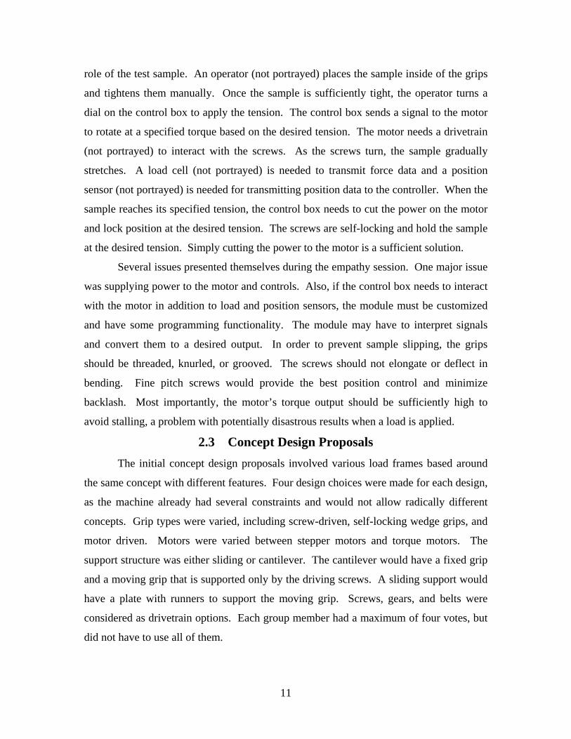
1 Control/Display Panel and Accessories Both $400
1 Vacuum interface Purchased $500
TOTAL ESTIMATED COST (without shipping) $6201
19

Figure 2.3 - Concept sketch - single screw internally driven
20

2.6 Concept 3 – Manually Driven Load Frame 2.6.1 Concept Overview
Concept 3 is a mechanically driven load frame with a drivetrain inside the
microscope chamber. The main features of this concept are screw-tightened grips, a
gearbox to screw drivetrain powered by a hand crank, and a cantilever mounting setup.
The potential benefit of this design is a lighter and cheaper frame, as no plates would be
used for sliding guides. Friction would be reduced without runners or a support plate. As
long as the grips are light and the screws are stiff and strong, bending deflection
shouldn’t be an issue with this design. However, if the screws bend too much, loading
would not be pure axial tension and force readings would not be accurate. As a result the
load must be kept uniaxial. The weight of the support on the fixed end should be fairly
small, as the gearbox weighs less than 2 pounds. Grips could be purchased, but another
cost-reduction option is a custom set of grips to fit the exact specifications of the
chamber. As a result, weight and size are minimized.
2.6.2 Design Features
Similar to other potential concept designs, some of the major components will be
purchased. A generic “black box” version will represent the purchased components until
decisions are finalized in the feasibility assessment. Further analysis will be done on the
gearbox and the other “black box” components after they are selected for the system.
On the fixed end, the gearbox and one grip will be fastened to an L-shaped
support. The support will be stiff, strong, and corrosion resistant to avoid contamination
of the vacuum chamber. The two power screws will support the weight of the free end
and drive it while applying tension or adjusting position before gripping. AISI 304
Stainless steel will be the material of choice for both grip supports because of its
corrosion resistance. All machined surfaces will be free of any cutting oils and
contaminants before installation to avoid contamination of the vacuum chamber.
Turning a screw on the jaw modules will loosen and tighten grips. Ideally, grips
will be purchased from Tinius Olsen, MTT, Instron, or another leading competitor.
Should the motor be eliminated from the design, grips can be purchased without
adversely affecting the budget. Tentative prices are around $2,000 for a set of Tinius-
Olsen grips that is ideal for this fixture. The grips will have a wedge mechanism, moving
21

the jaws closer together as a screw is tightened. The fixed grip will incorporate a load
cell to measure tensile force in the sample. Money saved from eliminating the motor can
be spent on the load and position sensors or possibly a vacuum seal through the chamber
door for an external crank.
A small display box will incorporate a live display for tension and position.
Functions within the display will allow both load and position to be zeroed. Wires will
run through an existing port in the microscope chamber and connect to a position sensor
on the grip and a load cell in the fixed grip.
Cost is the major factor in this design. A feasible design could be created for
$4,000-5,000, but several decisions must first be made. Grips could be machined, but the
issue would become incorporating the load cell in the grips. The potential shortcoming
with this conceptual design is the 15-20 minutes necessary to depressurize the chamber
after each load adjustment. A possible solution is to feed a flexible vacuum-sealed
driveshaft through the chamber wall, allowing tension to be adjusted dynamically. If the
cost limit is not exceeded, this design should be acceptable.
2.6.3 Preliminary Bill of Materials
Qty Description Purchased
or Machined
Price
(estimated)
1 Vacuum-rated gearbox Purchased $1500
1 Stainless steel for crank mechanism Machined $40
2 Power Screws Both $250
1 Load cell Purchased $500
1 Live display for load/position Both $100
1 Fixed end, Free end – grip support Machined $100
1 Base support Machined $50
1 Set (2) of wedge acting grips Purchased $2000
1 Set of assorted wires for electronic controls Purchased $50
50 Cap screws and washers (assorted sizes) Purchased $50
1 Control module for motor Both $100
TOTAL ESTIMATED COST (without shipping) $4740
22

Figure 2.4 - Concept 3 sketch (top)
Figure 2.5 - Concept 3 sketch (side)
Figure 2.6 - Concept 3 gearbox and crank interaction
23

2.7 Concept 4 - External Motor with Two Driving Screws 2.7.1 Concept Overview
The main feature of Concept 4 is that the motor supplying the tension is mounted
on the outside of the machine. The potential benefits of this design are more space within
the chamber for the rest of the load frame and the avoidance of problems with the motor
overheating. In a vacuum, air cooled motors will overheat if they are operated for too
long. The main challenge for this design is maintaining a good driving torque as the load
frame moves into focus under the electron gun.
2.7.2 Design Features
Most of the major components will be purchased. Depending on the price and
size constraints, sizes and locations may change somewhat. As a result, a generic black
box will represent the purchased components until decisions are finalized in the
feasibility assessment. Further analysis will be done on the motor and the other “black
box” components after they are selected for the system.
A vacuum interface for the motor and shaft will be mounted on the door. Because
of tight tolerances, this product must be purchased. A potential solution costs $2625.00,
which is expensive, but may eliminate some other costs in the process. The shaft in the
chamber is rated to 150 ounce-inches torque. The shaft will be connected to a gearbox
that will provide a torque sufficient enough to apply the desired tensile force to the
sample. The motor will power the driving screws, the means of applying tension.
A control box will incorporate a live display for tension and position. The control
box on this motor may aid in controlling the system. Buttons on the live display will
allow both load and position to be zeroed. An additional wire port will be added for the
load cell. The wire pass-through costs about $80.
This design, however, is practically impossible with the existing machine, due to
the support plate for the existing SEM position fixture. The plate enables tilt control and
partially obstructs the port that is targeted for the external motor interface.
24
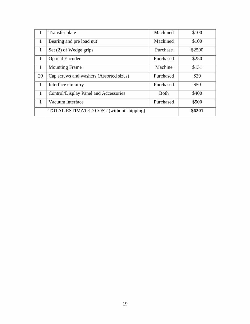
2.7.3 Preliminary Bill of Materials
Qty Description Purchased
or Machined
Price
(estimated)
1 Motor & Pass-Through (vacuum) Purchased $2750
2 Power Screws Both $250
1 Load cell & Wire Pass-Through Purchased $600
2 Grip supports Machined $200
1 Set (2) of wedge acting grips (Tinius Olsen) Purchased $2000
1 Set of assorted wires for electronic controls Purchased $50
50 Cap screws and washers (assorted sizes) Purchased $50
1 Gearbox Purchased $800
TOTAL ESTIMATED COST $6750
Figure 2.7 - Concept 4 - similar to other concept designs, except for the external motor.
25

3 Feasibility Assessment 3.1 Introduction
Evaluation is a critical part of the design process. Original designs are evaluated
at the concept stage and after the details of a machine have been finalized. Different
evaluation methods are required for different activities. Methods used for assessing
detailed designs are generally inappropriate for the evaluation of design concepts because
the specific details of the purchased equipment are not yet available at the concept stage.
In many cases, proprietary equipment will be selected and incorporated into a larger
design scheme. Therefore methods for comparing equipment are needed. Proprietary
equipment can be evaluated in great detail, but to carry out very detailed assessment of
large machines would be time consuming and, in most cases, inappropriate. In some
cases, only a limited amount of detailed information is available for the proprietary
equipment. Therefore, the equipment needs to be evaluated with respect to the particular
case under consideration. Qualitative and quantitative methods may be used according to
the requirements of individual cases.
In this case, a range of evaluation methods and principles were used to
qualitatively and quantitatively assess the four concepts. The attributes to be included in
this evaluation are resource, economical, schedule, and technical feasibilities. Methods
used for this comparison were Pugh’s method and a weighted evaluation.
3.2 Evaluation of design concepts For this project a weighted evaluation is used side by side with a Pugh evaluation.
In each case the resource feasibility is broken down into sufficient skills, sufficient
equipment, sufficient number of people, and availability of purchased components.
Components of the schedule feasibility include the chances of meeting the intermediate
mileposts, chances of meeting the PDR requirements, and chances of meeting the CDR
requirements. Economical feasibility will be scaled by the percentage of total required
funds allocated. Technical feasibility will be based on distinguished levels as depicted in
the evaluation worksheets.
26

3.3 Pugh Evaluation Pugh’s evaluation was a qualitative evaluation in which design concepts were
compared to a reference design concept. This method is similar to the ‘paired
comparison’ method of evaluation used in creative problem solving. The reference
concept was a derivative of the generic tensile testing configuration, scaled down to size
to fit in the SEM chamber. An evaluation matrix was constructed, (Table 3.1), consisting
of the four concepts, which are compared against the assessment criteria. The reference
concept was chosen as the datum. Each concept was then compared with the datum with
respect to each assessment criterion, or attribute, independently. If a concept was deemed
better than the datum with respect to a certain attribute then a plus sign was inserted into
the matrix for that attribute. If a concept was deemed to be worse than the datum with
respect to the attribute, a minus sign was entered into the matrix. If it was the same as the
datum, or if no judgment whatsoever can be made, then a zero was inserted. Thus the
pluses, minuses, and zeroes for each concept were totaled to complete the matrix. The
matrix highlights the strength and weakness of concepts. The objective is to eliminate
week concepts and to identify those strong concepts that are suitable for further design
work.
3.4 Weighted Concept Evaluation Also known as the systematic quantitative method, the weighted concept
evaluation was performed in six steps: defining the assessment criteria, setting the value
judgment, determining relative importance of criteria, predicting performance, converting
the performance to score values, and computing the overall value.
The assessment criteria resemble that of the Pugh evaluation except that they
estimate relative importance of attributes. Weights were developed through a comparison
of row attributes and column attributes and tallying the row, column, and overall totals.
The relative weights or importance of each attribute were normalized by dividing each of
the attribute total values by the sum of the total values.
Horizontal arrows signified that the row attributes were more important than the
column attributes. Vertical arrows signified that column attributes were more important
than the row attributes and a diagonal arrow signifies no significant difference between
row and column attributes.
27

Value judgment was set by defining a range of performance from an upper value
of perfectly acceptable performance to a lower limit that defines the threshold of
complete unacceptability. A score of 5 was given to the perfectly acceptable concept that
was much better than the reference concept, 4 points were awarded for a concept that was
better than reference concept, 3 implies same as reference concept, a value of 2 is given
for a worse design than the reference concept, and a value of 1 is given when a concept is
much worse than the reference concept.
The overall performance value is computed by the summation of the product of
the weight value with attribute score for each concept. The design concept with the
greatest overall value is the preferred choice. However, if concepts are very close in
score, the designers may not choose the best concept from the feasibility assessment, as
they would be practically equal.
A weighted evaluation was done for both the relative importance of the modules
and for the resource, economic, schedule, and technical feasibility criteria. The weighted
evaluations for the modules were shown in Tables 3.2 and 3.3. The weighted evaluations
for the various design concepts were shown in Tables 3.4 and 3.5.
28

3.5 Results
Table 3.1 – Pugh evaluation of concept proposals
Pugh Evaluation Worksheet
Baseline Concept Internal motor/gearbox -2 screws
ATTRIBUTE CONCEPT 1 CONCEPT 2 CONCEPT 3
Resource Feasibility
R1 Sufficient skills 0 - +
R2 Sufficient equipment 0 0 +
R3 Sufficient number of people 0 - +
R4 Availability of purchased components 0 - +
Economical Feasibility
E1 % of total required funds we have 0 - +
Schedule Feasibility
S1 Chances of meeting the intermediate mileposts 0 - +
S2 Chances of meeting the PDR requirements 0 - -
S3 Chances of meeting the CDR requirements 0 - -
Technical Feasibility**
T1 feasibility Level (L0, L1, L2, L3, L4) 0 0 0
Scores 0 7 4
Number of Pluses 0 0 6
Number of zeros 9 2 1
Number of negatives 0 7 2
Conclusions:
**Level L0: Are we trying to break the laws of science?
Level L1: Are fundamentally new inventions required?
Level L2: Has a similar technology been used before (by anybody)?
Level L3: Has the technology been demonstrated by our team?
Level L4: Has the customer tested the technology?
29

Table 3.2 - Relative weights for module importance to overall design
Table 3.3 - Weighted importance of modules for concept proposals
Table 3.4 - Relative weights for weighted concept evaluation
30

Table 3.5 - Relative weights for concept evaluation
Weighted Evaluation Worksheet
Baseline Concept Internal motor/gearbox -2 screws
ATTRIBUTE RELATIVE WEIGHT#
CONCEPT 1
CONCEPT 2
CONCEPT 3
Reource Feasibility
R1 Sufficient skills 0.083 3 2 4
R2 Sufficient equipment 0.097 3 3 4
R3 Sufficient number of people 0.014 3 2 4
R4 Availability of purchased components 0.153 3 2 4
Economical Feasibility
E1 % of total required funds we have 0.194 3 1 5
Schedule Feasibility
S1 Chances of meeting the intermidiate mileposts 0.028 3 1 4
S2 Chances of meeting the PDR requirements 0.167 3 1 2
S3 Chances of meeting the CDR requirements 0.194 3 1 2
Technical Feasibility**
T1 Feasibility Level (L0, L1, L2, L3, L4) 0.069 3 3 3
RAW SCORE 2.997 1.581 3.399
NORMALIZED SCORE 0.999 0.527 1.133
**Level L0: Are we trying to break the laws of science?
Level L1: Are fundamentally new inventions required?
Level L2: Has a similar technology been used before (by anybody)?
Level L3: Has the technology been demostrated by our team?
Level L4: Has the customer tested the technology?
31

3.6 Conclusion Based on the results of the two evaluation methods, two concepts will be
considered for future development. The main focus, however, will be devoted to the 2-
screw internal motor concept, which yielded the greatest overall performance value of 3.
This concept will consist of six modules. The concept will use a machined set of
threaded grips, an internally mounted stepper motor, a twin-screw drivetrain, external
mounted control and display panel, a fixed mounting frame, and a vacuum-friendly
interface for wire feedthroughs. There is a similar working model at Lehigh University.
The other concept, with the second largest overall performance value of 2.931, is
concept 3, which differs from the latter by employing manual power instead of the torque
motor. The concept will be pre-loaded by a hand crank prior to closing the SEM
Chamber. This concept will also serve as a backup plan, depending on the economical
feasibility of stepper motors and other purchased components for the preferred concept.
32

4 Objectives and Specifications 4.1 Design Objectives
The design objectives for the S.E.M. Load Frame, the key purposes and goals for
this project, must be met while taking into effect the constraints of the vacuum chamber.
The load frame must fit within the scanning electron microscope’s vacuum chamber. As
the load frame must work inside the vacuum chamber of the electron microscope
compartment all components of the frame must be designed to work safely within the
vacuum environment. While inside the vacuum chamber, the load frame must not
interfere with the electron gun or the detector. Such interference would compromise
image quality and possibly damage the machine if components come into contact with
each other. At least one set of working grips will be included in the load frame’s design
and be able to handle at least 2000 lbs of tension. These main grips will hold cylindrical
specimens with threaded ends. Samples will be easy to install, since the work needed to
install a sample will be minimal.
As the load frame will be the property of Dr. DeBartolo, it will have to be
modular and easy to install and remove from the load frame. In addition, the module will
be stored in the mechanical engineering facilities, but used at the CIMS building. As a
result it must be lightweight and easy to carry between buildings.
4.2 Performance Specifications The load frame must meet several performance criteria. In order to meet the
customer’s minimum needs, the machine must support a load of 2000 lb in tension and
200 lb in compression. For safety and logistical reasons, the machine must have the
capability of both position and load control, with a switch that allows the operator to
select either option. Position control is needed for adjusting the movable grip and
securing the test specimen. Load control will drive the sample during the tensile test, but
in the event of a fracture, position control may be used to halt motion of the grip.
Since the customer desires a display for load and specimen deflection an
automated control system will incorporate live displays for load and position. The
control system will remain outside of the chamber and will have a power source separate
from the SEM.
33

4.3 Design Specifications/Implementation Due to the design of the existing SEM position fixture, the load frame will be
customized to that specific machine. The position fixture contains several stepper motors
that control x, y, and z position, tilt, and rotation. Budget and time constraints prohibit
designing a new position fixture to accommodate the load frame. As a result, the rotation
module will be removed to make room for the load frame and provide a mounting
location for the load frame without removing the position fixture. To allow for easy
mounting, the design must be modular, consisting of several components that easily
assemble.
The operation of the machine involves a series of mechanical devices to achieve
appropriate sample tension. The drive train consists of a stepper motor, which couples to
a gearbox, driving a series of spur gears, which in turn drive a pair of ACME thread
power screws. One grip will remain fixed while the two ACME screws drive the other
grip. Custom designed grips will accommodate threaded cylindrical samples with a 1”
gage length. The motor control is located outside of the SEM vacuum chamber, so the
wires must pass through a vacuum-tight feed-through in the chamber door.
4.4 Evaluation Criteria Before installation of the product, it must meet a set of evaluation criteria. All
part designs will be verified by modeling in Pro Engineer and critical parts will be
evaluated for stress and displacement in ANSYS. Fatigue calculations will ensure that
the power screws and any fasteners will hold for the lifetime of the module (105 cycles
should be sufficient). In addition, torque calculations for the power screws will ensure
that the motor will meet its performance standards and avoid stalling. After verifying the
performance capability through simulation and development testing, the load frame will
be tested outside of the vacuum chamber by loading a sample specimen to maximum
tensile and compressive loads.
Other important criteria for the machine’s performance that must be met are as
follows: If a sample fails in the vacuum chamber, there will be safety constraints to
ensure that the sample will not damage the microscope. The drive train must handle the
specified loads of 2000 lb tension and 200 lb compression. Samples will be tightly
secured and should not loosen during operation. The module must fit in the chamber and
34

be easy to install. The surfaces of all parts must be corrosion resistant and free of any
impurities and oils to avoid contamination of the vacuum chamber. The automatic
controls must function while the chamber is sealed and provide a live load and position
feedback within reasonable accuracy.
4.5 Safety Standards Though no ASTM standard exists for vacuum tensile tests, several safety
precautions must be implemented in the design of the load frame. Vacuum environments
can be damaging to an air-cooled motor if it is operated for a long time, so motor use
must be limited. A regular motor may also experience outgassing in a vacuum, but a
vacuum rated motor would ensure no outgassing. Parts must be secured to the position
fixture inside the vacuum chamber. Due to the vacuum pressure and sensitivity of the
equipment, the system may take a few minutes to pump back to atmospheric pressure
before the chamber can be opened. Therefore it would be impossible to stop the pump
and immediately retrieve a loose part without inflicting any damage.
The effects of the electron beam may result in two problems, grounding and
overheating. As electron beams are fired at the surface, the load frame may become
charged during operation. It is important to note that a grounded connection must be
established with the fixture. To ground the load frame, an existing grounding clip from
the rotation module will be attached to the base of the tensile frame’s support structure.
As long as the motor is kept from overheating, heat will not be a problem for the fixture.
The electron beam will not cause a significant temperature change. The operators of the
machine stated that plastics and other insulators might have problems with melting
because they absorb the energy of the beam, but metallic structures will not experience a
considerable temperature change.
The existing position fixture was not designed to support heavy loads, and weight
must be minimized. Using the analysis features in Pro Engineer, weight can be
monitored for individual parts and for the entire assembly. The load frame’s weight must
not hinder the functionality of the existing position fixture. Most importantly, it must not
damage the position fixture.
35

5 Analysis and Synthesis 5.1 Design Structure Matrix (DSM)
5.1.1 Introduction
A software program run within Microsoft Excel, Design Structure Matrix,
analyzed the dependencies of various design decisions. A DSM model of the design
process was used to quantify a process configuration and lead to a logical order of design
decisions. Cost, duration or schedule, and variances in both are largely a function of the
number of iterations required in the process execution and the scope, or impact, of those
iterations. Since iterations may or may not occur (depending on a variety of variables),
this model treats iterations stochastically, with a probability of occurrence depending on
the particular package of information triggering rework.
This model characterized the design process as being composed of activities that
depend on each other for information. A change in that information results in a ripple of
change in the design. Thus, an alteration to one activity can cause a chain reaction
through supposedly finished and in-progress activities. Reworking is a function of the
probability of a change in inputs and the impact of the change in inputs. The model also
assumes independent activities can work concurrently.
5.1.2 Problem Statement
The goal of this procedure was to map the whole picture of systems and parameter
relationship to aid in understanding the implications of changing any parameter to the
others. It was limited to the scope of the project in two respects; first it is used after a
number of parameters have been established and second, it was a new technology that
needed to be tried and tested in the project due to high dependencies of parameters
associated with this project.
5.1.3 Results analysis
A total of nineteen system attributes were mapped out and modeled in the DSM
software. After three iterations it was realized that the dependencies are of high nature
and no further candidates were available to complete the bottom half as expected. It was
noted, however, that only sample size, load cell and applied loads could be addressed
independently with minimal impact of rework on other parameters. As a result, further
testing of the DSM was halted, as no iteration would produce the required results. In that
36

case the remaining attributes with feed forward dependencies will be treated one at a time
by assuming desired parameters and adjusting the rest of the others accordingly.
Figure 5.1 - DSM Matrix for the tensile load frame
5.2 Motor and Gearbox Selection The selection process for the motor and gearbox required the resolution of the
following issues: vacuum compatibility, torque requirement, size constraints, power
requirements, and cost. Vacuum compatibility greatly limited the field. Contact with 25
different motor manufacturers – makers of low force linear actuators excluded – yielded
referrals to three companies: Danaher Motion, Empire Magnetics, and Bay Side Motion.
Danaher was unable to assist the team as they did not make vacuum rated equipment, but
offered Empire Magnetics as a referral. While Bay Side is able to provide gearboxes
suitable to the laboratory vacuum, they do not manufacture motors with the capability or
gearboxes beyond a 100:1 ratio in the size range required. Also, the minimum pressure
of Bay Side’s vacuum rating was not available. Cost served to eliminate the servomotor
as an option. With servomotors, the necessary onboard components are expensive to
dissipate large quantities of heat from the motor in a vacuum environment. As a result, a
stepper motor was chosen.
37

Size and cost constraints make the selection of a NEMA 17 frame stepper motor
coupled with a 700:1 gearbox necessary. Potential solution included a complicated bevel
and worm gear setup or larger motors, which with a 100:1 gearbox (Section 5.3) is next
to impossible to fit, without even considering how to handle axial thrust control of the
gears. Empire Magnetics makes a 700:1 three-stage gearbox in both NEMA23 and
NEMA17 sizes. The NEMA17 can only transmit a maximum of 600 lb·in continuously;
loading over 600 lb·in will severely shorten gearbox life and it could fail at any time.
The NEMA23 gearbox can transmit 1040 lb-in before its life is threatened. Team chose
to adapt a NEMA17 motor to a NEMA23 gearbox, saving $400 compared to purchasing
the larger motor.
There are other advantages to using a NEMA17 motor instead of a NEMA23,
which include safety and simplicity. With a maximum motor torque output of 2 lb·in and
a gearbox efficiency of 0.72, it is impossible for the NEMA17 motor to damage the
NEMA23 gearbox. The maximum torque applied by the gearbox is 1008, based on the
motor limitations using Equation 5.1, where Tmax is the maximum torque, Ng is the ratio
of the gearbox (700:1), and Tm is the torque applied by the motor. Also the slimmer size
of the NEMA17 motor allows for positioning such that a 2.5:1 cylindrical gear ratio can
be used while keeping the center lines of the motor, gearing, and power screws in the
same plane, saving material cost and simplifying the machining setup.
ggmg NTT ⋅⋅= η (5.1)
Use of a three-stage continuous 700:1 gearbox was a costly, but worthwhile
decision. With a 100:1 ratio, the number of independent gears outside of the gearbox
could number at least 6, and require the use of bevel or worm gearing to provide
additional reduction. The efficiency losses and axial thrust created with these gearing
combinations have not even been fully calculated, because the team unable to find a
combination to even meet the space constraints and preserve the safety of gear shafts.
Each complexity in the power train introduces additional possibilities for error, additional
complexities of manufacture, and additional tolerances. A 700:1 gearbox requires the
precision alignment of three holes and precision thickness of the base housing. These
parts were easily fabricated in the machine shop.
38
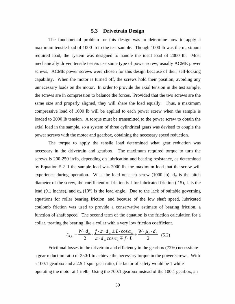
5.3 Drivetrain Design The fundamental problem for this design was to determine how to apply a
maximum tensile load of 1000 lb to the test sample. Though 1000 lb was the maximum
required load, the system was designed to handle the ideal load of 2000 lb. Most
mechanically driven tensile testers use some type of power screw, usually ACME power
screws. ACME power screws were chosen for this design because of their self-locking
capability. When the motor is turned off, the screws hold their position, avoiding any
unnecessary loads on the motor. In order to provide the axial tension in the test sample,
the screws are in compression to balance the forces. Provided that the two screws are the
same size and properly aligned, they will share the load equally. Thus, a maximum
compressive load of 1000 lb will be applied to each power screw when the sample is
loaded to 2000 lb tension. A torque must be transmitted to the power screw to obtain the
axial load in the sample, so a system of three cylindrical gears was devised to couple the
power screws with the motor and gearbox, obtaining the necessary speed reduction.
The torque to apply the tensile load determined what gear reduction was
necessary in the drivetrain and gearbox. The maximum required torque to turn the
screws is 200-250 in·lb, depending on lubrication and bearing resistance, as determined
by Equation 5.2 if the sample load was 2000 lb, the maximum load that the screw will
experience during operation. W is the load on each screw (1000 lb), dm is the pitch
diameter of the screw, the coefficient of friction is f for lubricated friction (.15), L is the
lead (0.1 inches), and αn (10°) is the lead angle. Due to the lack of suitable governing
equations for roller bearing friction, and because of the low shaft speed, lubricated
coulomb friction was used to provide a conservative estimate of bearing friction, a
function of shaft speed. The second term of the equation is the friction calculation for a
collar, treating the bearing like a collar with a very low friction coefficient.
2coscos
2,cc
nm
nmmLR
dWLfd
LdfdWT ⋅⋅+
⋅⋅⋅±⋅⋅
⋅⋅
=µ
απαπ
m (5.2)
Frictional losses in the drivetrain and efficiency in the gearbox (72%) necessitate
a gear reduction ratio of 250:1 to achieve the necessary torque in the power screws. With
a 100:1 gearbox and a 2.5:1 spur gear ratio, the factor of safety would be 1 while
operating the motor at 1 in·lb. Using the 700:1 gearbox instead of the 100:1 gearbox, an
39

additional 2.5:1 reduction by spur gears is sufficient to reach the maximum torque and
include a factor of safety of 5. Though this is an excessive level of safety, no
intermediate gear reductions were available. The spur gears on the power screws (2.5
inches) are connected to the gearbox by a 1 inch pinion gear. For the spur gears, they
will survive the maximum load. The maximum stress per tooth is around 90 ksi when the
machine is operating at maximum capacity. After computing gear stresses, shear stresses
were computed for the shafts using Equation 5.3. The stress on the output shaft can be
found using equation 5.3.
3
16dT
⋅⋅
=π
τ (5.3)
The major problem with the drive train was connecting the spur gears to the
power screws. Machining the component from a single piece was not even a possibility,
considering the expense of cutting an ACME thread and the time required to machine a
2.5 inch diameter shaft (needed for the spur gears) down to a 1 inch power thread. A
contact with years of machine shop experience estimated that the cost would be $4,000-
5,000 for the two power screws. The best solution was to purchase an ACME threaded
rod, spur gears, and appropriate bearings, washers, and fasteners. The method of joining
these parts came under much scrutiny. A square broach, a pin, and a key were considered
as methods of fastening. The pin would be the simplest design. Cutting the thread off of
the end of the ACME rod and drilling a matching hole in the collar, the components
would be inserted into each other and a hole will be drilled for a dowel pin. Keys are
good at transmitting torque, but are weak in axial loading. A broach is functional, but the
square hole would be costly to machine with wire EDM (electrical discharge machining).
The pin was able to transmit the torque from the gear to the collar and from the collar to
the shaft. The stresses in the pins were 45 ksi and 34 ksi for the gear/collar and
collar/thread, respectively. However, to achieve a safe pin, the diameter was ¼ inch with
a 1 inch power screw. Collar length would increase to allow more thickness to account
for the hole.
The final design was to select a larger ACME shaft (1-10) to allow material for
stepping down the end of the shaft to accommodate bearings and gears. Drilling through
the center axis of the gear, the gear fits on the 0.500 diameter at the end of the shaft, held
40

in place by the diameter step, washers and a 10-32 screw. The 5/8 inch diameter shaft
section passes through a clearance hole in the fixed end and is held by a radial load
bearing inside the fixed end. Stress in the power screw is not a problem (Section 5.8), as
a vacuum safe lubricant was used to reduce friction. PTFE thickened Krytox vacuum
lubricant was viscous enough to remain on the components inside the vacuum and
provide the necessary protection. Bearing stress in the thread is about 22 ksi, not
lubricated, and about 7 ksi lubricated, which are both below the yield strength of 30 ksi
for AISI 316 stainless steel.
5.4 Gripping Mechanism 5.4.1 Specifications of the Grips
One of the most crucial components to provide stability and safety in the SEM
Tensile Stage is a set of grips to secure the metallic specimen. A machine worth several
hundred thousand dollars is potentially damaged if a sample is released while under load.
Without a firm grip, the tensile test results would be null and void. It was in the best
interests of the team to properly analyze the gripping problem and design a viable
solution.
When designing the grips, a major decision was whether the grips should be
designed for predetermined specimen geometry or if the specimen should be designed
based on the grips. This was easily determined since a standard ASTM specimen exists
for a variety of sizes and samples could easily be acquired or manufactured [4]. As a
result, the grips were designed first with the specimen geometry adjusted to fit within the
grips.
Grip specifications were determined by the environment and stress conditions for
the operation of the machine. As with the design of other components within the SEM
tensile stage, it was important to safely operate in a vacuum pressure of 10-7 torr, and this
component was no exception. Also, it is very important that the grips do not contain any
grease or oil to avoid contamination of the SEM chamber. Since the design goals for the
tensile stage are to load a specimen to a maximum of 2000 lbs tension and 200 lbs
compression, it would be best to design the grips to be able to withstand a tensile of force
of 3000 lbs, a factor of safety of 1.5. Most importantly, the grips must also be small
enough to fit within the narrow packaging envelope of the tensile stage.
41

5.4.2 Purchased or Machined?
With a number of purchased components already in the design, the team faced
mounting costs. The original idea was to purchase a set of small, flat, grips. Initially, it
was decided that these grips should be purchased instead of designed and machined
because of time constraints and machining issues. It became evident, unfortunately, that
the specific type of grips that were needed would be too expensive and consume too
much of the budget (Table 5.1).
Table 5.1 - Grips available for purchase Manufacturer and Type Load Capacity (lb) Cost
MTT – Flat Wedge Action Grips 5000 $4,800
Tinius Olsen – Flat Wedge Action Grips 2250 $1,910
Instron – Remanufactured Wedge Action Grips 5000 No response
With potential prices that consumed a large portion of the budget, several cheap
alternatives were considered. Some of which included self-locking grips and a custom
design that for a flat dog bone specimen, but the flat designs didn’t allow for the samples
to be examined across both width and thickness. Therefore, the team decided to design
and manufacture a set of grips for a cylindrical sample with male threaded ends. This
design was met with approval from the team because it solved three major problems. The
grips would be very easy to manufacture. A 1-inch diameter cylinder of stainless steel
could be drilled and tapped with the sample’s thread size. Given the machine’s small
height envelope of 3 inches, the size of the grips is ideal. The cost to manufacture these
grips would be much less than $100, freeing up funds for other design features.
5.4.3 Final Design of Grips
The grip is simple to manufacture and easily replacable. Created from a small,
cylindrical piece with a threaded through hole on the center axis, the free end grip is 1
inch in diameter and about 1.5 inches long. The hole will be tapped with a 3/8-24 thread,
the same size of thread used on the Futek load cell that is designed to handle up to 3000
lbs. The fixed end will use the load cell as a grip. The sample threads into the female
end of the load cell and the male end will of the load cell is threaded into the fixed end of
42

the frame. The material choice is AISI 303 stainless steel because of its corrosion
resistance and machinability.
As with any design, the decisions were verified through calculations. To just trust
the thread specifications for the Futek load cell is not enough to ensure that the threads
are safe. It is advisable to check stresses to make sure the threads can withstand the force
applied to the grips. This is the only calculation that is of any concern to the grips
because the weakest part of the grips is going to be the threads. The following equation
gives the stress applied to one thread, given an applied load:
tp
ddP
i
⋅−⋅⋅
=)(
422π
σ (5.4)
P is equal to the force applied to the threads, which in this case is 2000 lbs, and
d²-di² is the tensile area of the 3/8-24 threads. The variable t/p is the number of threads in
which the load is being applied. For this case the length of the male end of the specimen
fitting into the grip is designed to be 9/16 inches. At 24 threads per inch, a total of 13.5
threads are in contact. Therefore, the average stress per thread is around 6.75 ksi, which
is safely below the yield strength of the material (30 ksi) of the grips.
5.5 Base and Frame The base and supporting frame were designed around the existing SEM position
fixture and the purchased load frame components. The base of the load frame must serve
three purposes: to act as a platform to support the load frame, to act as an apparatus to
hold the SEM’s longitudinal position resolver so that the sample can be positioned under
the microscope, and to act as a means to connect the test specimens to the SEM’s
grounding path.
To support the load frame, the base will be composed of two pieces. For
corrosion resistance and strength, the base is machined from AISI 303 stainless steel bar
stock. A pattern of holes in the center of the plate matches that of the SEM position
fixture base plate. A set of three holes is used for mounting the fixed end to the base.
The base plate must hold the position resolver, a function that was previously done by a
module that is removed for the installation of the load frame. The position resolver
mounts on the side of the base in the same location where it would normally be located
on the removed rotation module. With the position resolver mounted to the base plate,
43

the existing position control for the stage will function normally. In regards to providing
a path to ground, the plate must be composed of sufficiently conductive steel to avoid a
buildup of charge in the load frame. It is an important facet, however, because without a
path to ground the electron gun would charge up the specimen quickly and a discharge
could damage the equipment inside the SEM. However, the SEM is equipped with a
warning to alert the operator when the system is not properly grounded.
The fixed end plate is the critical component to manufacture, controlling
alignment and position of various components. On the plate, mounting holes are
precision machined to allow for the placement of the gearbox/motor assembly, base plate,
power screws, and the necessary bearings to align the power screws. Composed of 1.25-
inch plate stock, deflection should be minimal, despite the number of mounting holes for
the motor, base, and load cell. Stress and deflection were verified in ANSYS (Chapter
7). As this component was manufactured accurately, assembly and alignment issues were
be negligible.
Acting as the crosshead, the free end travels along the power screws. Supported
by the screws, the free end crosshead is also composed of 1.25-inch thick AISI 303
stainless steel for manufacturability and corrosion resistance. The two holes to
accommodate the power screws are threaded with a 1-5 2G ACME tap. An additional
mounting hole locates the bolt that secures the threaded grip.
5.6 Control and Display 5.6.1 Beginning Estimates
To generate the
necessary torque at
reasonable speeds, it
has been decided to run
the stepper motor with
an applied voltage of 24
volts. At this potential
the motor should be
able to reach a
maximum speed of
44
Figure 5.2 - Torque vs. speed curves for the Empire Magnetics U17-2 vacuum rated stepper motor. This graph demonstrates that at 24V a maximum speed of nearly 20 rotations per second can be maintainedand still generate the necessary torque (15 oz inches).

nearly twenty rotations per second (RPS) and still generate the desired torque of about
15oz inches (Fig 5.2). With a complete gear ratio of 1750:1, and ten threads per inch on
the ACME screws, this translates to free-end movement at a rate of about an inch every
14.6 minutes (875 sec/rotation). The motor requires 200 steps/rotation, when each of four coils is
activated in turn. To generate the ‘parallel’ curves seen above, these four coils are wired
in parallel to function as two coils. This generates a slower drop off in the torque speed
curves and changes the resolution per step to 3.6 degrees. Thus there will be only 100
steps per rotation for our application. At a rate of 20 rotations/second requires the controller to
have the ability to drive the motor with a 2 kHz signal to reach the maximum allowable
motor speed. However, due of the characteristics of the controller device, this upper limit
will never be achieved using this setup.
5.6.2 Control response constraints
To reduce expenditure, a method of control was found that could be implemented
for no monetary cost. This choice, however, comes with cost in performance. A
Measurement Computing device called the miniLAB 1008 was received from the
Mechanical Engineering department for no cost. This device has no ability to do
processing independent of the host computer. It is connected to the host via a USB 1.0
connection. Thus its abilities are all limited fist by the bandwidth of the USB 1.0
connection and second by the software response time of the host computer. The
miniLAB 1008 has two analog output channels that have a collective output rate of 100 samples/second. This means that one channel can be used to run 100 samples/second, or both
channels can be operated simultaneously at a reduced rate of 50 samples/second. The result is
a maximum driving frequency of 100Hz, a maximum speed of one rotation/second. With the
gearing this means movement of the free end at a rate of 57µinches/second. Although this rate
of movement is seemingly very slow (one inch takes just under 5 hours to traverse) the
rate of change in load is much more substantial.
5.6.3 Sample Response Characterization
Through relatively simple calculation, using the relation of stress and strain
allowed by the modulus of elasticity, the applicable rate of change for the load on the
sample can be revealed. The stress on the sample is equivalent to the force applied over
45

the sample’s cross-sectional area (Eq 5.5). Strain is the change in length of the sample
proportional to the original length of the sample before force was applied (6).
AF
=σ (5) llS ∆
= (6) SE *=σ (7)
A stress and strain are related through the modulus of elasticity (7). This formula can
then be manipulated, and the rate of change of length substituted for ∆l to estimate a rate
of change in the load applied to the sample. Thus: l
EAlF ∗∗∆=∆
Assuming the
5.3, the rates of cha
assuming that the p
output frequency of lbs/sec. This, as we
Table 5.2 – Assumed worst case sample characteristics
Sample characteristics
Length 1.25 (inches)
Radius 0.125 (inches)
Modulus Elasticity 9900000 (PSI)
Table 5.3 - Rate of sample loading for various motor speed characteristics Loading Characteristics
Motor Speed Rate of Load Change Time to run full 2200 lb Range
(RPS) (lbs/sec) (sec) (min)
0.0625 1.39 1584.5 26.4
0.125 2.78 792.2 13.2
0.25 5.55 396.1 6.6
0.5 11.11 198.1 3.3
1 22.22 99.0 1.7
10 222.16 9.9 0.2
20 444.31 5.0 0.1
characteristics of the cylindrical sample to be as are state in Table
nge for various rotational speeds are shown in Table 5.4. Thus
arallel connection reduces the step size by half, and a maximum
100Hz the device can achieve 1 RPS and a loading rate of ±22.2
ll as data for other operational speeds is shown in table 5.4.
46

Pessimistically the team can assume 2 – 5 minutes to move the entire valid load range of
the device at the highest motor speed possible with the miniLAB 1008TM.
5.6.4 Hardware Design Fundamentals
Figure 5.3 - The MOSFET H-Bridge used to drive the stepper motor coils. A single motor coil is simply modeled here as a 10 Ω resistor (R1). This model was developed to determine if this configuration could source the necessary power to the motor coil. Additions to this circuit in implementation include capacitances to quite oscillations caused by the coil’s inductive nature and level shift conditioning of the miniLAB 1008TM output. Here the control voltages are represented by V3 and V4, sinusoidal voltage supplies.
Figure 5.4 - Simulation of MOSFET H-bridge seen in figure n+1 demonstrating proper application of power to the motor coil for voltages sufficient to saturate the MOSFETs. The 10Ω resistor modeling the motor is subject to 1.81Amps at 18 volts, values satisfactorily close to our desired values of 2 Amps and 24 Volts.
47
This analysis asserts that a 24 volt driving voltage would be feasible and produce
a reasonable rate of control. Thus a 24 volt 50 Watt single ended power supply was
acquired. The fact that the power supply is single ended limits the precision of control
without exponentially increasing the complexity of the driving mechanism. Thus a
configuration of transistors commonly referred to as an ‘H-Bridge’ was implemented to
provide the required bi-polar drive. The H-bridge was implemented using metal oxide
field effect transistors (MOSFET) to provide maximum efficiency at high currents. A
model of the circuit was assembled to prove the functionality and feasibility of the
design. The model is shown in Figure 5.4 and the results in Figure 5.5. The probe colors
match the plot of the specific variable measured at that point. All plots are voltages with
the exception of the blue line which represents the flow of the current through the motor
coil. The output of the miniLAB 1008TM can be fed through a level shift and directly into
the H-Bridge which will in turn feed a motor coil, thus control of the motor is
accomplished.
A 10 volt excitation voltage must be fed to the load cell so that output can be read.
This will be generated from the 24 volt supply and fed into the load cell. Noise on the 24
volt power supply is expected to be a major issue while the motor is running due to the
inductive nature of the coils. All attempts possible will be made to quiet the effect of the
motor on the power supply. Feeding the sensor from the noisy 24 volt power supply is
feasible because sampling of the sensor signals cannot be achieved simultaneously with
the movement of the motor due to limitations of the miniLAB 1008TM. Thus to read
sensor signals the motor will be stopped and measurements will be taken in a fraction of a
second. This will allow the settling of the supply voltage and add minimal delay to the
achievement of the user desired load.
Filtering of the sensor signals will require only a low pass stage to filter out
excessive high frequency noise as the signals to be measured are expected to change
relatively slowly (temperature and load). Any additional or more complex filtering or
numerical analysis can be achieved through LabVIEW functions, or virtual instruments
(VIs).
48

Figure 5.5 - A visual summary of the hardware layout and connections.
5.6.5 Control Software
With all aspects of the hardware interface laid out as can be seen in Figure 5.6, all
that remains is the software to interface the system to the user. The sponsor of the project
Figure 5.6 - This figure shows the general layout of the LabVIEW program. A series of VIs interprets the users commands and outputs them to the miniLAB 1008tm, which in turn dictates the signals to the tensile stage and interprets inputs from the stage
preferred that control be implemented through National Instruments LabVIEW version
6.1. The miniLAB 1008TM came with “Universal Libraries for LabVIEW” that offer
49

functions, or VIs, for interacting with the miniLAB device. The software that is provided
to control the tensile stage is built up from these universal libraries and as such, can either
be used as is by the end user, or merely as a set of guidelines for defining their own
functionality for the machine.
There are two main types of VIs provided as a result of this project. First there
are VIs that prompt, direct, and interpret
the user’s commands into signals to be
output to the device. The second type of
VI simply outputs the generated signals
to the device, or receives data from the
t
p
i
t
m
d
o
a
Figure 5.7 - An example GUI demonstrating the range of control devices, and their possible applications in the case of the tensile load stage. The GUI interface will be easily end-user definable.
tensile load frame. The VIs that send
and receive signals to and from the
device are built most directly on the
Universal Libraries for LabVIEW that
came with the miniLAB1008TM. The
subVIs, as they are called, that were
developed for this project in this
situation mainly serve to simplify the
interaction with the miniLAB 1008TM
device, and make programming in this
environment more directly oriented with
he resulting actions of the tensile stage. This is intended to simplify the development
rocess for an individual who may not fully understand the functions of all the devices
nvolved, but knows how they want the tensile stage to respond to their commands.
The other type of VI developed for this project is oriented more towards defining
he user interface and dictating a sequence of actions to the user to set up and use the
achine. These VIs would include signal generation and user prompts. A layout of a
eveloped function can be seen in Figure 5.7.
Using these VIs, the user can take inputs and outputs and generate whatever plots
r GUI devices they want or need for their application of the tensile stage. Figure 5.8 is
n example interface that shows several of the control input/outputs available for GUI
50

development in LabVIEW. The tensile stage software will come with a default GUI, but
the end user will always have the option of easily designing custom interfaces or
functions.
5.7 Vacuum Interface In the design of an electromechanical system to in a vacuum, an important
consideration is the transfer power and data signals through the chamber wall. One ideal
port is available in the SEM door for transmitting necessary signals. Motor signals,
temperature feedback, and the load cell data travel through the door to the control module
in the laptop computer. Major companies manufacture or sell these feed-throughs
included Nor-Cal Products, MDC Vacuum Products, ISI, and PTL vacuum.
The port available in the SEM has a diameter of 1.75 inches. After viewing
several schematics, it was found that a 2.75 inch flange was required. At 10-14 wires
need to pass through the chamber wall, 4-8 for the stepper motor, 2 for the thermocouple,
and 4 for the load cell). The first option was from MDC, which consisted of a twenty pin
feed-through. Model number MDC647055, it protrudes into the chamber with 3.14 inch
pins. An advantage of this feed-through is the possibility of upgrading of the load frame
with the inclusion of a position encoder. This is a feature that would not have been
accommodated by other components under consideration, which included a ten pin
feedthrough and a 9 pin D-type connector.
The wires are removable from the feed through to allow for easy installation and
removal. Using crimpers, the wires for each component are attacted to a ceramic disk for
spacing and insulation. The disk and crimper assembly attaches to the pins on the feed
through, which is coupled to the airside plug. Wires from the airside plug are routed into
the control box.
5.8 Stress Calculations for Critical Components Though fatigue life and yield strength were initial concerns, the design is safe for
operation. The excessive factor of safety in some components allowed everything to be
safe in fatigue, as fatigue life for stainless steel is generally equal to or slightly greater
than the yield strength, especially for low cycle fatigue [9]. Calculations shown below
were the most critical in the design process.
51

Table 5.4 - Selected stress calculations Part Section of Part Stress Allowable Stress FS
------------ ---------------------------- KSI KSI ------------
Free End Vertical Section Through ACME
CTR Line 4 30 7.50
Free End Vertical Section Through CTR 10.61 30 2.83
Free End Bolt Cross Section at Thread 22.36 30 1.34
Free End Bolt Individual Thread 6.94 30 4.32
Cylindrical
Fastener Cross Section at Thread 2.96 30 10.14
Compression
Collar Cross Section 0.3 30 100.00
Cast Iron Nut Cross Section 4 43.5 10.88
ACME Shaft Thread 4.5 30 6.67
ACME Shaft 1"-10 to 5/8" Step 3 30 10.00
ACME Shaft Radial Load Bearing (Maximum
Bending Moment) 15.77 30 1.90
ACME Shaft 5/8" to 1/2" Step 17.35 30 1.73
ACME Shaft Keyway 15.64 30 1.92
Needle Roller
Thrust Bearing Spec: 2170lbf @ 11,000 RPM
1100lbf
@0.7RPM 2170lbf
MINIMUM
1.97
Needle Roller
Radial Bearing Spec: 2330lbf @ 16,000 RPM 266lbf @ 0.7RPM 2330lbf
MINIMUM
8.76
Fixed End Vertical Section Through CTR 8 30 3.75
Gearbox 1008lbf-in MAX Production;
1040lbf-in MAX Allowable 220lbf-in Design 1040lbf-in MAX
MAXIMUM
4.73
Pinion Gear 60.4KSI Sim, T=1040lbf-in@
0.86RPM, large Face Wd 64.86 180 2.78
Spur Gear All Gears 8620 Case Hard (Must
be for shock load) 25.95 180 6.94
Base/ Fixed End
Connection
Screws Designed to Withstand
Maximum Possible Moment Due
to Externally Applied 100lbf
Force
N/A N/A N/A
52

6 Preliminary Design Several changes were made to the preliminary design and are discussed in detail
in Chapter 8. The initial cost estimate for the preliminary design was $7,500. At this
stage of the design, the necessary components and materials were purchased from
suppliers.
6.1 Part Numbers for Pro Engineer files -1st digit =1 if component, =2 if assembly
-2nd digit =0 if purchased, =1 if manufactured
-3rd digit = module number (1=motor/gearbox, 2=drivetrain, 3=grips, 4=base/frame,
5=control, 6=vacuum interface, 7=miscellaneous
- 4th and 5th digits=component number within module (01, 02, etc.)
Figure 6.1 Preliminary Design
53

7 Engineering Models 7.1 Part and Assembly Modeling
7.1.1 Modeling with Pro/Engineer
In addition to modeling and assembling the components in three dimensions
before manufacture, computer aided modeling offered several other advantages. In
transferring the models to detail drawings, Pro/Engineer allowed for the analysis of
fabrication and assembly issues before any of the components and materials were
purchased. Manufacturing issues were considered as the components were created and
assembly issues were considered as the components were assembled. Critical dimensions
and tolerances were resolved with the use of the analysis features, which allow for
checking fits through measuring distances, weight analysis, global clearance, and global
interference. Pro/E served a final check to review all of the dimensions before the parts
were manufactured. In addition, the assembly drawings with regular and exploded views
were created from the models and a bill of materials was automatically generated. All of
the mechanical parts and some of the electrical components were modeled in
Pro/Engineer (Figure 7.1). A great deal of time, money, and effort was saved through the
use of Pro/E to analyze the design, essentially allowing the team to create a prototype
before the prototype was built.
Figure 7.1 – Components such as the fixed end were modeled in Pro/Engineer
54

Figure 7.2 – Component fits were tested with a model of the SEM position fixture
7.1.2 Finite Element Analysis with Pro/Mechanica and I-Deas
In order to verify the safety of the design and accuracy of stress calculations,
several of the fabricated parts were analyzed with finite elements. Though most of the
components were purchased and were rated to specific loads, the fabricated components
needed to be evaluated before proceeding with the design. The high stress components
were tested, which included the gears, power screws, and the free end. The gears were
analyzed in Pro/Mechanica, but the power screws and free end were analyzed with I-
Deas. Though Mechanica worked most consistently with the existing models, some team
members had more experience with I-Deas. Finite element analysis is never the sole
method of design, as garbage in is equal to garbage out. Models were carefully designed
and constrained, as boundary conditions have a drastic impact on stress magnitudes and
locations. Calculations were done first to estimate the stresses and were a used for
verification of the finite element methods.
Gears, which were case hardened, were not expected to fail in the current design.
The pinion gear and 2.5 inch gears were modeled as 3D solid elements in Pro/Mechanica
structural analysis. The bore surface was constrained in all degrees of freedom and the
gears were loaded with a tangential uniform force of 440 lb to the surface of one tooth,
55

the equivalent contact force from the maximum gearbox torque. The number of elements
was rather large due to the complicated geometry from the several gear teeth. For each
model, displacement, Von Mises stress, and shear stress were checked.
As expected, the pinion gear was the weaker gear, due to its smaller size and
smaller hole to diameter ratio. Its maximum Von Mises stress was 97.3 ksi, which is a
factor of safety of 1.85 with respect to the yield strength. Shear stress was the greatest at
the root of the tooth and was 54.5 ksi. In comparison, the calculated value was 64.86 ksi.
Displacement was also relatively small, as the maximum displacement was .000973
inches at the tip of the tooth. Stress and displacement contours for the pinion are shown
in Figure 7.3. A shear stress contour plot is shown in figure 7.4
Figure 7.3 - Von Mises stress and displacement in the pinion.
Figure 7.4 - Shear stress in pinion and gear.
56

As expected, the spur gear did not approach its failure criteria. Due to a larger
size and a smaller ratio of bore diameter to overall diameter, stresses were smaller. The
maximum Von Mises stress was 49.7 ksi, compared to a yield strength of 180 ksi. The
factor of safety is 3.6 for the spur gears. The maximum shear stress was 27.5 ksi,
compared to a calculated value of 25.95 ksi. Displacement was less than half of the
maximum displacement in the pinion, as it was only 0.000437 inches at the tip of the gear
tooth. As with the pinion, the numbers were in the same general range and the two
components were deemed safe. Stress and displacement contour plots are shown in
Figure 7.5 and a shear stress contour plot is shown in Figure 7.4.
Figure 7.5 - Von Mises stress and displacement in the gear
When modeling the power screw in I-deas, the shaft was created to almost the
same geometry except that the threads were only modeled for a total length of 0.750
inches. The length of the shaft in which the ACME threads are be engaged was all that
was necessary to model. The surface of the threads facing away from the other end of the
shaft was constrained in every direction to simulate the conditions of the shaft before
enough torque is applied to overcome the self-locking properties of the ACME threads
when the shaft is applying 1000 lbs of force to the free end. The shaft is also constrained
in the x and z directions along the surface of the shaft that is inserted inside the needle
roller bearing, since those are the directions in which the bearing restrains the shaft. The
rest of the boundary conditions were all applied as distributed loads along certain
surfaces of the shaft.
57
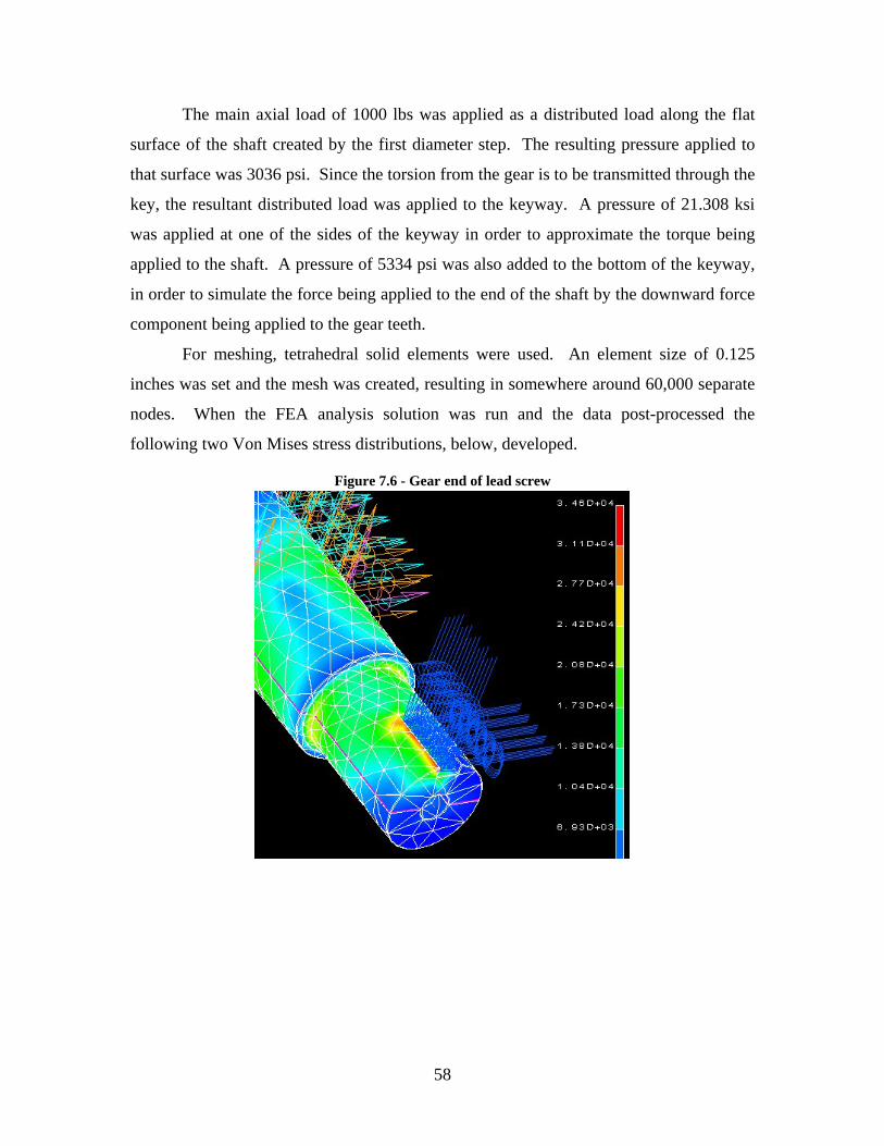
The main axial load of 1000 lbs was applied as a distributed load along the flat
surface of the shaft created by the first diameter step. The resulting pressure applied to
that surface was 3036 psi. Since the torsion from the gear is to be transmitted through the
key, the resultant distributed load was applied to the keyway. A pressure of 21.308 ksi
was applied at one of the sides of the keyway in order to approximate the torque being
applied to the shaft. A pressure of 5334 psi was also added to the bottom of the keyway,
in order to simulate the force being applied to the end of the shaft by the downward force
component being applied to the gear teeth.
For meshing, tetrahedral solid elements were used. An element size of 0.125
inches was set and the mesh was created, resulting in somewhere around 60,000 separate
nodes. When the FEA analysis solution was run and the data post-processed the
following two Von Mises stress distributions, below, developed.
Figure 7.6 - Gear end of lead screw
58

Figure 7.7 - ACME end of lead screw
Figure 7.6 shows a max stress of 34.6-ksi around the edge of the keyway, which
can most likely be attributed to the local stress concentrations of the pressures that are
applied there. Because of these local concentrations, the stress calculated in that region
may not be 100% accurate. Most likely the stress in that region is around 27.2-ksi, which
is marked in orange. One area of interest in this figure is the fillet edge on the diameter
step. It is here that a stress concentration is expected to occur, and the Von Mises stress
curve supports that theory. The area of interest is surrounded by a shade of green but the
round is noticeably yellow, meaning that most likely the stress there is about 27.7-ksi.
The Von Mises stress plot in Figure 7.7 supports preliminary analytical
calculations. The ACME threads were not a point of failure for the power shaft. The
stress plot shows a max stress of around 5.5 ksi, which is much lower than the max stress
to be achieved at the other end of the shaft.
The material used for the power screw was 304 Stainless Steel. This grade of
stainless steel has a tensile strength of 73.2 ksi and yield strength of 31.2 ksi.
Considering that the above boundary conditions that were set were at an absolute worst-
59

case scenario it appears that the loads in the power screw will not approach the yield
strength. Also, since the load frame will see at most 100,000 cycles, fatigue failure is not
an issue. Theoretically this shaft should also be able to withstand 106 cycles, since the
fatigue life for stainless steel is nearly infinite for loads below the yield strength [9]. It
appears that the lead screw should withstand the operating conditions that it was designed
for.
The finite element analysis of the free end was done using the I-DEAS software
package. Symmetry could have been used to cut computation time but the part was
simple enough that modeling in quarter-symmetry was not necessary. The initial design
for this part required a one thousandths press fit of iron nuts into the holes for power
screws. This press fit would create a pressure of 2000 psi in those holes. The 2000 lb
load was applied over the counterbore for the grip and the bases of the counterbores were
constrained not to move in the Z (tensile) direction. After meshing and running the
solution a maximum stress of 13.5 ksi was obtained, which translates to a factor of safety
of 2.2. The locations of max stress were along the outside, where the wall thickness from
the press fit is thinnest and along the setscrew holes in the direction of applied force.
For the compressive case, 200 lb was applied to the circular area in contact with
the grip collar. The maximum stress was found to be 15.1 ksi producing a factor of
safety of 2. The stress concentration in this case is greater than for the other case, despite
of the drop in load by a factor of ten because there is much less area supporting the load.
While machining the ACME nuts and free end, the press fit was removed from
the design. The same boundary conditions and loads were applied as before, with the
exception of the press fit. The maximum stress was found to be 8.34 ksi producing a
factor of safety of 3.6. The stress concentration is on the edge where the iron nut would
contact the free end. As expected, the stress is higher along the edge of the hole with the
most bending stress (Figure 7.8).
60

Figure 7.8 - Von Mises stress in the free end
Finally, an analysis was run on the “Compressive” stress state without the press
fit. After solving, it was found that the stress was largely negligible for the entire piece.
Analysis showed that the part in its final form has a factor of safety of 3.6 and that the
removal of the press fit from the design was a good engineering decision from the
perspective of stress in the free end.
7.2 Testing the Product for Reliability and Quality 7.2.1 Integrated Test Plan for SEM Load Frame
The SEM tensile load frame involved the development of six modules. Each
needed to be tested for technical design specification and customer requirements as well
as safety requirements associated with incorporating the system in the SEM platform.
The scope of testing was limited by the project duration, budget allocation and technical
competency of the design team. It should be noted that this project involved the design
and commissioning of the tensile testing system and will differ from commercial projects
by virtue of the constraints governing the size and user requirement, making it a unique
case never attempted anywhere.
61

The focus of the test plan will take into account the developmental process, from
the needs assessment to production and deployment. It should be noted, however, that
there are two primary approaches to this kind of testing; one is to test during development
and second during operation. It is possible to run the two procedures concurrently for
well-funded complex projects or programs involving sophisticated subsystems and
involving high-risk catastrophic failures. Since the scope of this project terminates with
deployment, it is reasonable to integrate a test plan to cover the development of the
system, which will have a test planning team consisting of the customer and the owner of
the SEM machine (NCR³).
Figure 7.9 - Planning flow for Integrated Test [ref]
Test Planning Team Individual Test
Planners (CIMS)
Project Office
Test Performers
Test
Policies
and
Ground
Rules
Summary
Specifications
Test procedures Test reports
Test Planning
Forms
Integrated
Test Plan
Management
Summary and
Status Vol.1
Special Studies
Test integration
Project direction
Contract negotiation
7.2.2 Individual Test Plans
The Development Test and Evaluation for this project will be categorized into
three parts. The first part covers individual components or parts. The second covers
subassemblies, and the third covers deployment testing. The first two categories were
incorporated into the concept feasibility assessment phase. The team members on their
respective assigned modules of the design will conduct testing. Most of this part of
62

testing will be completed after the preliminary design review and will verify that
components or subsystems satisfy the customer needs and technical specifications.
7.2.3 Component Processing
Many parts were outsourced from vendors and upon delivery they were routed to
assembly or manufacture, depending on whether they were stock material or finished
components. For stock material, the first check was to verify the material specifications,
as stated in the order form. A manufacturing sheet has been developed for every
fabricated part to state all manufacturing requirements, including the module, part
number, sequence of machine operations and related checks as well as engineering
drawings. Otherwise, if parts were found to be defective at this stage, they were sent
back to the supplier for replacement.
During manufacture, some of the parts possessed features that required
specialized operations and multiple set-ups. For each part routed for manufacturing, the
detailed processing requirements depended on the type of operation required and the
availability of facilities and machines. Most of the parts required normal machine
operations like milling, turning, boring, etc, which generated scrap material. In light of
this undesirable situation, the stock was ordered to minimize scrap and reduce processing
time. Tolerances and dimensions were recorded and compared with the requirements and
further action was taken depending on whether the specifications were satisfied or not.
Finally, the finished part advanced to assembly. Those that did not meet specifications
were routed for reworking or were scrapped.
7.2.4 Subassembly Testing
Once parts met and satisfied the requirements, they were routed for subassembly
integration. During this phase, individual components were joined to others with special
techniques that have been outlined in the feasibility assessment. The operations varied
depending on each subassembly requirement. It was decided to verify interactions and
tolerances at this stage to eliminate any undesirable conditions that may arise before
integrating into respective modules. Each subassembly will have its own set of
instructions, as per the specifications depicted in the feasibility assessment phase. For
components that did not require manufacturing processing, but need to be integrated into
63

subassemblies, re-working of parts that have been routed through manufacturing
compensated any discrepancies encountered.
7.2.5 Deployment Testing
When all components and subassemblies satisfactorily met their requirements,
subassemblies were incorporated into their respective modules. During this phase, all
stakeholders were invited for a complete system test. This test was conducted with the
system outside the operating chamber. Recorded data included maximum force and
displacement to verify customer specifications. Safety features were tested at this phase
and the software was calibrated. The module was later verified in the chamber once the
functionality was tested. Documentation made available to the customer included
assembly instructions and an operation manual.
Figure 7.10 - Material flow for SEM load frame manufacturing.
Receiving Manufacturing Assembly Deployment Test
• Lathe • Mill • Drill • Work
Table
• Torque • Tolerances • Vacuum • Function
• Supplier Info.
• Part number
• Specification
• Routing
Parts
Stock
• Control o Power o Safety
Stop • Display
o Force o Distance o Motor
Temp
64

8 Final Design
8.1 Changes from Preliminary Design 8.1.1 Gripping
The setup for gripping evolved into a simpler, more ergonomic design.
Previously, three cylindrical grips were employed with one grip on either end of the load
cell on the free end and one on the fixed end. However, with the load cell on the free
end, there was no feasible way to grip and ungrip the samples. The problem was solved
rather easily, as the male-ended load cell was replaced with a male/female-ended load
cell. The size was perfect to fit in place of the cylindrical grip on the fixed end and
eliminated an additional grip that had been on the other side of the load cell. The new
setup is very easy to use and the samples can be installed in three basic steps. The
sample is threaded into the load cell, the grip is threaded onto the sample, and the end
bolt is passed through a protective collar and threaded into the grip. The collar was once
a two-piece cylindrical design that was removable to leave room for unscrewing the grip
without removing the bolt. The intention of the collar was to hold the grip in place,
provide a bearing surface during compression tests, and to provide a method of securing
the end bolt if the sample fractured. With the current design, there was no need to use
65

the two-piece design and it was replaced with a cylindrical component that resembled the
grip.
Figure 8.1 - Final design of gripping module
Grip
End bolt
Collar
Load cell
Figure 8.2 - Preliminary design of gripping module
Grips
Collar
8.1.2 Shaft and Bearing Setup
Though the preliminary design of the shafts was feasible, the team decided to
reduce the necessary torque with the redesign of the lead screws. Addition of bearings,
washers, and vacuum-safe lubrication reduced the necessary torque considerably. The
66

design employs larger power screws (1 inch instead of ¾ inches) to allow for stepping
down the shaft twice. The first section is held by needle roller bearings inside the fixed
end and supported on either end by needle roller thrust bearings (Figure 8.3). Everything
on the shaft is held together with a 5/8-18 nut. A keyway on the end of the shaft allows
power transmission from the gear and a #10-32 cap screw secures the gear to avoid any
axial motion.
Figure 8.3 - Assembly of bearings, washers, and gears to power screws
8.1.3 Free End and ACME Nuts
In order to provide a threaded surface for the screws to interface, several designs
were considered. Originally, a nut and flange design (see Figure 8.1) was considered, in
addition to ACME tapped holes. Due to the price of taps, which far exceeded $150 each,
the ACME nut concept was chosen. Using machinable gray iron cylindrical ACME nuts,
the components were easily adjusted to the 1.250-inch diameter and 0.750 inch length.
Holes in the free end provided a light interference fit and two ¼-20 setscrews were also
employed to secure the ACME nuts.
8.1.4 Custom Gear Design
In order to keep the gears strong and avoid any deformation or destruction, they
were custom designed. With the help of a contact at the Gleason Works, the gears were
designed and manufactured free of cost. Materials available in purchased gears were
mostly plastic, brass, and steel. In order to increase the yield strength, case hardened
8620 steel was chosen for the material. The gears have a pitch of 16 and a contact angle
67

of 20°. Manufactured with pregrind hobs, the gears reached a tolerance class of AGMA
11 before heat treatment an AGMA 9 after heat treatment. They will withstand a
maximum stress of 180 ksi and maximum torque beyond the limit of the gearbox. They
mate with the small diameter on the end of the power screws and interface with a key to
transfer the torque.
8.2 Cost Analysis The team was limited to a budget of $7,500 for the design and fabrication of the
SEM tensile load frame. Standard components such as fasteners and washers, which
usually can be obtained for free in the shop, were purchased because the black oxide
finish would not be safe in vacuum conditions. Several washers and fasteners were
composed of stainless steel, plastic or titanium. Manufactured components were
fabricated from 303 stainless steel rod and bar stock and 304 stainless steel power screws.
Most of the budget was spent on the vacuum rated motor and gearbox from Empire
Magnetics. Space constraints and environmental conditions limited the options, resulting
in a higher price tag than initially expected ($5500). The gears were obtained for free
from the Gleason Works and several of the electrical components were also obtained for
free from the Computer Engineering Department. As a result, the total cost of $6614.08
stayed well below the allotted budget of $7,500. An item and supplier cost list is given in
Table 8.1.
Table 8.1 - Cost List Part No. Component Qty Unit Cost Total Cost
10101 Stepper Motor 1 $991.00 $991.00
10102 Gearbox 1 $2,789.00 $2,789.00
10201 ACME Screw (RH) 1 $132.00 $132.00
10202 ACME Screw (LH) 1 $174.89 $174.89
10203 ACME Nut (RH) 1 $35.67 $35.67
10204 Spur Gear 2 $0.00 $0.00
10205 Pinion 1 $0.00 $0.00
10206 Needle Bearings 4 $2.13 $8.52
10207 Needle Bearings 2 $4.64 $9.28
10208 ACME Nut (LH) 1 $51.70 $51.70
10302 Cap Screws 1 $5.82 $5.82
68

10307 Load Cell 1 $900.00 $900.00
10501 Control Box 1 $0.00 $0.00
10503 Stepper Drive 1 $0.00 $0.00
10504 Power Supply 1 $15.00 $15.00
10505 Serial Cable 1 $16.00 $16.00
10601 Electrical Interface 1 $413.25 $413.25
10602 Air Side Connector 1 $47.50 $47.50
10603 Ceramic Spacers 2 $10.45 $20.90
10604 Wire Crimpers 4 $57.00 $228.00
10701 Cap Screws 1 $5.58 $5.58
10701 Cap Screws 1 $4.27 $4.27
10702 PTFE Washer 1 $5.87 $5.87
10703 Bearing Washers 10 $0.75 $7.50
10704-5 Washers 1 $6.67 $6.67
10706 Nuts 1 $7.90 $7.90
10707 Washers 1 $5.10 $5.10
10708 Washers 1 $9.48 $9.48
10709 Washers 1 $5.01 $5.01
10710 Key Stock 1 $1.89 $1.89
11301, 3 Stainless Steel 1 $16.20 $16.20
11306 Specimens 1 $12.31 $12.31
11401, 2 Stainless Steel 1 $82.32 $82.32
11403 Stainless Steel 1 $36.98 $36.98
N/A Motor Adaptator 1 $325.00 $325.00
N/A Vacuum Lubricant 1 $146.02 $146.02
N/A PTFE Tape 1 $2.02 $2.02
N/A PTFE Tape 1 $4.06 $4.06
Subtotal $6,540.76
Shipping $73.32
Total $6,614.08
8.3 Design for Manufacture 8.3.1 Introduction
Product Design for Manufacture and Assembly (DFMA) presents an overview of
the factors influencing product design and the manufacturing cycle which include
69

component design and analysis, design for manufacturability, function, design of manual
assembly, and manufacturing processes.
DFMA software is a combination of two complimentary tools, Design for
Assembly (DFA) and Design for Manufacture (DFM). DFA software allows for
systematic analysis of a product design with the goal of reducing manufacture and
assembly costs, improving quality and speeding time to market. DFMA includes DFA
and the part cost estimation software DFM. Consolidating parts into elegant and
multifunctional designs, DFA reduces the complexity of a product. DFM software then
allows the engineer to quickly judge the cost of producing the new design and to compare
it with the cost of producing the original design.
The early and accurate cost estimate provided by DFMA software allowed the
team to proactively budget resources while the product was still under development.
During the development stages of a new product, cost and cost drivers deserve careful
consideration. The goal was to improve the product without increasing the costs.
However, this project tackles a new case. Usually, designers have no way of accurately
quantifying whether the specific innovation they are contemplating will increase or
reduce overall product cost. The Design for Manufacture and Assembly suite of software
gave the team tools to use during the product development cycle to analyze and
understand the cost effects of design decisions.
8.3.2 Design Phase
Control of part count is paramount to maintaining cost targets and overall
functionality. DFA software tools helped simplify the product by focusing the attention
of design team on part count and part count reduction. Product simplification was
achieved through the application of the software’s industry-tested minimum part count
criteria. The analysis allowed the determination of the theoretical minimum number of
parts that must be in the design for the product to function as required. Identifying and
eliminating unnecessary parts also eliminated unnecessary manufacturing and assembly
costs. Suppliers were a rich source of feedback during product simplification,
particularly if one of the options is to consolidate multiple parts into one part with
multiple features.
70

The potential for cost reduction continued when the team selected the optimal
materials and manufacturing processes for each part in the design. Using DFM software
tools, a thorough understanding of the primary cost drivers associated with manufacturing
the product was established (a benchmark for what the product "should cost."). Central
to the “should-costing” approach is accumulating real information about manufacturing
costs and noting where specific costs arise in your design. Large costs in product
development are associated with design manufacturability, so sharing “should-costing”
information with suppliers can make your collaboration more fruitful.
8.3.3 Design Optimization
The models in DFM Concurrent Costing software guide the user through an
assessment of alternative processes and materials and provide cost information for the bill
of material. Costs update automatically as you determine tolerances, surface finishes,
and other part details. Gradually, as effective shape-forming processes and considering
how to modify part features to lower cost, the product becomes more optimized.
8.3.4 Results
Achieving higher DFA indices, a measure of assembly efficiency, depends on the
following: part integration, ease of assembly, part inserted from top, part is self aligning,
part does not need to be aligned, one hand assembly, no tool required, assembly in single
linear motion and part secured by insertion.
The total number of parts was 61. The theoretical minimum number of parts
calculated by the software is 15 with a design efficiency index of 6.32%. There are 27
different parts. The total product cost is $7246.48 with total manufacturing tool cost of
$1800.00. These figures are based on a 10-year production plan for 100 products. The
manufacturing cost for each part fabricated was estimated to be $100.00.
A base part was chosen for other parts or subassemblies to join. The structure is
divided into subassemblies, which are pre assembled. There are three subassemblies: the
motor, free end and the fixed end assemblies. The fixed end has two subassemblies,
namely the right and left shaft assemblies.
71
8.3.5 Suggestions for Redesign
Discussed below is the list of suggestions from the DFMA software and the
team’s replies. Many of the changes suggested by DFMA were not applicable to the
design for reasons such as machining cost and loss of function and flexibility.
Incorporating integral fastening elements into functional parts or changing the
securing methods will eliminate the need for separate fastening elements such as screws,
nuts and keys. It was necessary for our design to have the above to support disassembly,
repair and replacement parts or service.
Combining connected parts or attempting to rearrange the structure of the product
could eliminate the parts whose function is solely to make connections. The Key was
identified as one of these parts but could not be substituted; it was incorporated to
maximize torque transmission.
Reduce the number of parts in the assembly by combining with others or
eliminating parts. The parts are mainly washers and bearings, which aid in alignment and
could not be replaced. However, combining a part with another may eliminate parts such
as fasteners.
Consider redesign of the individual assembly parts that require a grasping tool
such as the key. Changing the key would require another method of connection and
hence will be not changed.
Consider redesign of the individual assembly parts that require severe insertion
difficulties such as the bearings. This assembly set up was required for this fit and will
not be changed at this time.
Only three parts were identified to pose ergonomics difficulties for the assembly
worker. The bearings require significant pressure to insert and the motor pinion gear and
drive gears require a cover as the have sharp edges.
8.4 Included Parts Drawings for all of the manufactured parts and the major purchased components
are included in Appendix 1. The parts modeled in the assemblies are listed below. All
but the vacuum components and fasteners have a drawing. Some part numbers were used
on parts that are no longer in the design. Hence, some numbers were skipped.
72

20001 – SEM load frame (2 sheets)
20002 – SEM chamber with load frame (2 sheets)
20003 – Electrical feedthrough assembly
10101 – Motor
10102 – Gearbox
10201 – Right handed ACME power screw
10202 – Left handed ACME power screw
10203 – Right handed ACME nut
10204 – 2.5” spur gear
10205 – 1” spur gear
10206 – Needle-roller thrust bearing
10207 – Needle-roller thrust bearing
10208 – Left handed ACME nut
10307 – Load cell
10601 – Vacuum rated 20 pin feedthrough
10602 – Air side plug
10603 – Ceramic spacer
10604 – Wire crimpers
10700 – Cap screw - 10-32 x .5
10701 – Cap screws – 10-32 x 2
10702 – Compressible PTFE washer
10703 – Washer
10704 – Spherical washer
10705 – Spherical washer
10706 – Nut
10707 – Clamp washer
10708 – Shim washer
10709 – Shim washer
10710 – Key
10711 – Set screw – ¼-20 x 3/8
10712 – Cap screw – 3/8-24 x 2.5
73

11301 – Cylindrical grip
11303 – Compression collar
11306 – Specimen
11401 – Fixed end
11402 – Free end
11403 – Base
74

9 Production Planning 9.1 Material Considerations
The choice of material for any component within a design is crucial. Many
different aspects have to be considered in order to choose what best works for the
problem at hand. The material has to have sufficient properties in order to effectively
perform in its operating environment, i.e. tensile strength. Also, the material must be
able to be formed or machined into its specified component with certain degrees of
accuracy. Lastly, cost must be taken into consideration. Budgets cannot be exceeded and
if the material costs too much then it will be of no use. For the SEM Tensile Load Frame
all of these aspects were taken into consideration when choosing what materials to use
when making all the different components within the design.
One of the metals most widely used within the load frame was austenitic stainless
steel, specifically AISI 303 stainless steel. Stainless steel was used to manufacture the
free and fixed ends of the load frame, the grip, and the grip collar. The power screw
shafts (both left and right handed) and many of the fasteners were composed of AISI 304
(also known as 18-8) stainless. For all of these components it was found that stainless
steel had sufficient strength and stiffness in order to sustain the stresses applied to the
load frame. It also resists corrosion, which is very important so as to reduce the
possibility of contaminating the electron microscope chamber. In addition, it does not
outgas, to decompose or evaporate, at the vacuum pressure in which it will be placed, and
the cost of the material was low enough to fit into the allocated project budget.
The base of the load frame was constructed out of ½ inch thick aluminum. It was
decided to use aluminum for the base instead of steel for a number of reasons. Firstly,
aluminum is much easier to machine than stainless steel, therefore cutting down
production time. Secondly, strength and stiffness for the base was not nearly as much of
an issue as with other components because its only function is to fasten the load frame
onto the base of the microscope chamber. Thirdly, the aluminum was readily available
and added no cost to the project.
The gears were made out of 8620 case hardened steel. This steel was chosen
because of its high yield strength (180 ksi). Because of the torques acting on the gears,
the potential shock loads would be too much for the gears to handle if stainless steel were
75

to be used. Therefore gear teeth stripping would have occurred. The case hardened steel
can easily handle the applied stresses as well as well as not outgas in the vacuum
environment. It is not as resistant to corrosion as stainless steel, however, so care must
be taken so as not to allow any rust to form on the gears. Because of the difficulty to
machine 8620 steel and the overall difficulty in making gears, The Gleason Works
manufactured the gears.
For the 1-10 ACME threaded nuts in the free end, 3-inch diameter nuts were
purchased from McMaster-Carr for custom machining. The two metals in which
McMaster Carr offered these parts were in bronze and iron. Tin has a low vapor
pressure, and brass was potentially a problem with outgassing. Though brass was assured
by the Microelectronic Engineering Department to be safe, the iron inserts were chosen.
Some slight rusting could be a problem so care will be taken with handling and cleaning.
Figure 9.1 - Removing a large amount of material from the fixed end
9.2 Tooling Design and Machine Setup All of the work done on the free end, fixed end and base of the load frame was
done on a milling machine. All processes done on the milling machine were accurate to a
thousandth of an inch, with the aid of digital coordinate readouts for the x, y, and z-axes.
Cutting speeds used for machining the fixed and free ends were much lower than what
was used for the base. This was because the base was made out of aluminum and
material could be removed much faster than it could be for the stainless steel fixed end
and free end. The flats for the ACME nuts were also machined on the mill.
The power screws, grip, grip collar, and ACME thread inserts were all machined
on a lathe. The speeds they were turned at were between 150-200 rpm. They could not
be turned at much higher speeds without causing damage to either the parts and/or the
76

carbide tool bits. The accuracy achieved on the lathe was, like the milling machine, to
within one thousandth of an inch, but was instead achieved though the dials used to adjust
the location of the cutting tool. Due to the decreased cutting speed, the feed rates were
fairly slow. Also, the amount of material removed in one pass was kept small, about
0.030 inches for the threaded nuts and other cylindrical components, because the metals
were difficult to machine.
In the case of the power screws, the external threads and 5/8-shaft section were
sanded to fit cleaner in the fixed end of the load frame. Emery paper was used instead of
a cutting tool because the change in diameter needed to only be about one thousandth of
an inch, which was better suited to be removed by emery cloth. Great care also had to be
taken when cutting threads within the power screw shafts, because of the strength of the
stainless steel. It is easy enough to break a tap in aluminum but in steel the threat
becomes even greater.
9.3 Manufacturing Process Sheets Process planning involves the transformation of part or product definition data
into detailed production instructions. Production data may include materials, geometry,
and topology, tolerances, and demand volume. According to Alting and Zhang [ref]
(1989) this process can be summarized in ten steps. The steps include: interpretation of
product design data, selection of machining process, selection of machine tools,
determination of fixtures and datum surfaces, sequencing of operations, selection of
inspection devices, determination of production tolerances, determination of the proper
cutting conditions, calculation of standard times and costs, and generation of process
sheets and numerical control code.
The plan depicts detailed manufacturing, assembly, test, and service instruction in
a normal industry arrangement. However, for this particular project the plan was slightly
modified to focus on operations, machine selection, engineering drawings, supplier name,
part number and total manufacturing time and part material description, machine tools
and verification. This information was then consolidated into a manufacturing route
sheet for each part that required indoor fabrication. For ready to assemble parts, the sheet
will have drawings, and other relevant information without the machine code, machinist
assignment and processing times.
77

As part of the team quality standards, the manufacturing route sheets provide the
basis for continuation of manufacturing information and the relevant manufacturing
sequence used to fabricate the parts. This will also serve as record for improvement and
as a reference for all fabricated parts. This included the tooling changes that resulted
from changing operations during the manufacture of parts. It was observed that some
parts required special attention during manufacture due to the limitation of the tool
availability and material constrains in manufacturing and tool selection. Therefore, every
sheet was updated accordingly to the operations used in the machine shop. The
manufacturing route sheet thus serves as a record of all activities involved in operations
as well as a quality control reference during fabrication.
Figure 9.2 - Manufacturing process sheet for the free end
78

10 Pilot Production 10.1 Manufacturing Difficulties
Despite the relatively fast production, the project encountered some
manufacturing difficulties along the route to success. Though AISI 303 is considered a
free machining alloy, it is still stainless steel. No special cutting tools were required, but
cutting speeds were drastically reduced. As a result feed rates were also reduced.
Despite the slow cutting speeds, only ten parts were machined. Fabricated parts included
two ACME shafts, two ACME nuts, the base, fixed end, free end, grip, collar, and a
sample.
The fixed end, which required a large cutout for the motor mount, was the first
component to create machining difficulties. Using a standard end mill, only .030 -.060
passes were made and with an inch of material to remove, something needed to be done.
The cutter was glowing cherry red from the heat. A roughing cutter of 1.9 inches in
diameter was used to clear out the remainder of the material. With a slow steady feed,
the cutter machined the motor mount section in a total of 5 passes. Large holes for the
power screws also created problems. In order to machine the 5/8 diameter holes, a pilot
hole was first drilled with a 3/8 bit. Counterbores and bearing bores were machined with
the use of end mills, rather than use flat bottom drills, since counterbore tooling was not
available in the specified size.
The free end was the only other source of trouble, due to the massive amount of
material that was removed. Most of the lessons learned from the fixed end machining
were applied to the free end and it was machined without any problems. As with the
fixed end, the excess material was removed as the component was trimmed to the proper
length and width. Clearance holes for the ACME taps were first piloted with several
sizes of drills to keep material removal minimal and ensure a clean cut.
The ACME nuts, though fabricated from gray iron, caused some manufacturing
issues. The 1.375 inch nuts were machined from 3 inch cylindrical nuts. Though gray
iron was machinable, material removal was kept to a maximum of .030 inches in
diameter for each feed, due to excessive noise. The parts took roughly an hour and a half
per part to machine, once the setup issues were resolved.
79

10.2 Assembly Design The only major problem facing the design team was the assembly of components
with several degrees of freedom. In order to ensure proper alignment and a consistent
location of several key components, the team incorporated several assembly guides. The
ACME nuts were ground flat on the top and bottom surfaces to be secured by the
setscrews. Once the nuts were secure within the counterbored surface in the free end, the
screws were aligned so that the free end was parallel to the fixed end. The free end/shaft
subassembly was fitted with the appropriate bearings and washers and was added to the
fixed end, which already had the bearings. The additional nuts and washers were added
before everything was secured with a jam nut. Screws were adjusted so that they were
aligned with a parallel block and the surface of the free end. Gears were aligned and the
shafts were marked with locations for keyways. After cutting the keyways and fitting the
keys, the load frame was assembled without any problems. To ensure that the position
and alignment of components is kept consistent, a center punch was used to mark the
upper end of the ACME nuts and the free end. Gear bores were matched to a specific
power screw and the gear for the right-handed power screw was marked on its inner
surface with a center punch. If components are replaced, such as the ACME nuts or the
power screws, the machine should be assembled and realigned before the flats on the nut
or keyways on the shaft are machined.
10.3 Manufacturing Pictures The following pictures show the load frame in various stages of manufacture.
Figure 10.1 - The load frame was carefully assembled to check fits before cleaning.
80

Figure 10.2 - Machining the iron nut
Figure 10.3 - Drilling holes for ACME nuts in free end
81

Figure 10.4 - Gears were tested with a makeshift motor shaft.
Figure 10.5 - Test samples were machined to a 1-inch gage length
Figure 10.6 - Finished load frame awaits a motor.
82

10.4 Recommendations for Improvement Though the design is successful in meeting its primary goals, some improvement
can be made on weight, position accuracy, and the control system. The weight of the
module was not given much consideration during the design, as other constraints such as
strength, stiffness, and corrosion resistance were dominant. High strength aluminum may
be a suitable replacement, but the team avoided the use of aluminum in load bearing
components because of the superior stiffness and strength of stainless steel. In a test
application, deflection should be kept to a minimum in the test apparatus and focused
primarily in the sample. With aluminum samples in a stainless steel load frame, the
machine should never yield or fail before the samples.
For position accuracy, a position encoder could be added to obtain a stiffness
estimate. Due to cost constraints, the team eliminated the encoder. One issue with
position accuracy is the compliance of the machine. A compliance curve would have to
be created by testing an extremely stiff material and recording the displacement of the
system. The displacement of the system will be subtracted from the travel in the free end
to obtain the actual extension in the sample. Even with a compliance curve, there is no
substitute for an extensometer. Position resolution is only accurate if an extensometer is
used, and neither can be used in destructive testing inside the vacuum chamber without
opening the chamber to remove the extensometer.
The control system can’t be optimized until the motor arrives, which will be in
early June. Internal paperwork delayed the purchase of the motor and gearbox due to
their high cost and the team was not able to optimize the control code before the project
deadline.
While the prototype is an embodiment of sound mechanical design, there are
some minor flaws to account for. Most notable among these flaws is a slight wobble of
the cantilevered free-end, only noticeable without a sample in the grips, as it is advanced
or retracted. The undesirable movement is very slight and not likely of sufficient
magnitude to affect the stresses in the sample or frame significantly. However, it is
unintended and, therefore, its’ existence must be explained. The sources of wobble and
slight oscillatory misalignment are beyond the control of the team for reasons deriving
from budget and project scope. Listed in the order of probable greatest effect, they
83

include: the grade of thread tolerance used, the interface between the ACME nuts and the
free-end, and the limitation of available machining accuracy. All three are functions of
cost, although the second is, also, to a large degree, a problem of adequate space. Cost
was a problem until the gears were obtained for free, but the team was not aware of the
gear price until after the threads were ordered.
A 6C ACME thread class, and the associated lead accuracy and straightness, were
it available to our budget, would eliminate any wobble perceptible to the naked eye. Of
course it would introduce the problem of hole placements accurate beyond the machining
capability of the RIT machine shop. Only 2G ACME, general purpose, thread and
corresponding nuts, were within the scope of the budget, even before considering other
implications of an increased tolerance.
Standard nut and flange combinations are not possible in this instance due to inner
and outer flange diameter constraints eliminating all possible choices from the field. To
tap the ACME threads would require the purchase of both left-handed and right-handed
taps. The choice of a less conventional thread pitch only serves to further increase this
cost. Only the best attempt at a precision fit of a gray iron nut, turned to a proper outer
diameter, is feasible.
A tensile load frame is a precision piece of equipment. As the scale decreases, so
does the increment of precision. At best, machining accuracy is limited to 0.001in. Also,
ordered parts have their own tolerance ranges and errors which must be provided for.
The quality of the finished prototype is unmistakably good, especially when its’ status as
a first generation prototype is considered. Again, the deviations in the product do not
seem to have a noticeable impact on any testing conducted.
84

References [1] Vinci, R.P., 2000, "Mini-Tester Capabilities,"
http://www.lehigh.edu/%7Erpv2/minitensile_tester.pdf
[2] In Situ Tensile Testing Machine and Sample for a Scanning Electron Microscope,
Chiron et al., 1997. US Patent number 5,606,168.
[3] Nagy, Campbell, and Davidson, 1983, “High-temperature, cyclic loading stage for the
scanning electron microscope,” Rev. Sci. Instruments, Vol 55 no. 5, May 1984, pp. 778-
782.
[4] ASTM E8-01, Annual Book of ASTM Standards, Vol. 03.01
[5] Fundamentals of Machine Component Design, Juvinall, Marshek, 3rd edition, 2000.
[6] Integrated Product Testing & Evaluation. H. Gilmore, H.Schwartz. New York 1986.
[7] Testing to Verify Design & Manufacturing Readiness, Mc Graw – Hill, Inc 1993.
[8] Defense Systems Management College, Test & Evaluation Management Guide, Fort
Belvoir, VA: DSMC, March 1988, p.2-8
[9] Stainless Steels – Chromium and Nickel, Technical Data, Allegheny Ludlum
Corporation, Pittsburgh, PA, 2003.
85

Appendix Appendix 1 – Drawings for assemblies and parts.
86