Embed Size (px)
Citation preview
cui.com
date 07/12/2016
page 1 of 9
SERIES: PDQ30-D DESCRIPTION: DC-DC CONVERTER
FEATURES• up to 30 W isolated output• industry standard 1” x 1” package• 4:1 input range• single/dual regulated output• over voltage, input under voltage lockout, and short circuit protections• 1,500 Vdc isolation voltage• five-sided shielded case• remote on/off control• output trim• -40 to 105°C temperature range• efficiency up to 90%
MODEL input voltage
output voltage
output current
output power
ripple & noise1
efficiency
typ(Vdc)
range(Vdc) (Vdc)
min(A)
max(A)
max(W)
max(mVp-p)
typ(%)
PDQ30-Q24-S3-D 24 9~36 3.3 0 7.5 24.75 75 88
PDQ30-Q24-S5-D 24 9~36 5 0 6.0 30 75 90
PDQ30-Q24-S12-D 24 9~36 12 0 2.5 30 100 89
PDQ30-Q24-S15-D 24 9~36 15 0 2.0 30 100 89
PDQ30-Q24-D12-D 24 9~36 ±12 0 ±1.25 30 100 88
PDQ30-Q24-D15-D 24 9~36 ±15 0 ±1.0 30 100 88
PDQ30-Q48-S3-D 48 18~75 3.3 0 7.5 24.75 75 88
PDQ30-Q48-S5-D 48 18~75 5 0 6.0 30 75 90
PDQ30-Q48-S12-D 48 18~75 12 0 2.5 30 100 89
PDQ30-Q48-S15-D 48 18~75 15 0 2.0 30 100 89
PDQ30-Q48-D12-D 24 18~75 ±12 0 ±1.25 30 100 88
PDQ30-Q48-D15-D 48 18~75 ±15 0 ±1.0 30 100 89Notes: 1. At full load, nominal input, 20 MHz bandwidth oscilloscope, with 10 µF tantalum and 1 µF ceramic capacitors on the output. 2. All specifications are measured at Ta=25°C, nominal input voltage, and rated output load unless otherwise specified.
PART NUMBER KEY
Base Number Packaging Style:D = DIP
PDQ30 - QXX - X XX - D
OutputS = singleD = dual
Input Voltage Output Voltage
For more information, please visit the product page.
cui.com
date 07/12/2016 page 2 of 9CUI Inc SERIES: PDQ30-D DESCRIPTION: DC-DC CONVERTER
INPUTparameter conditions/description min typ max units
operating input voltage 24 Vdc input models48 Vdc input models
918
2448
3675
VdcVdc
surge voltagefor maximum of 100 ms24 Vdc input models48 Vdc input models
50100
VdcVdc
current 24 Vdc input models48 Vdc input models
3.91.95
AA
under voltage shutdown
24 Vdc input models, power up24 Vdc input models, power down48 Vdc input models, power up48 Vdc input models, power down
8.58.01716
VdcVdcVdcVdc
remote on/off1 turn on (3.5~75 Vdc or open circuit)turn off (<1.2 Vdc)
filter pi filter
input reverse polarity protection no
input fuse
6 A time delay fuse for 24 Vdc input models (recommended)3 A time delay fuse for 48 Vdc input models (recommended)
Notes: 1. CMOS or open collector TTL, reference to –Vin.
OUTPUTparameter conditions/description min typ max units
maximum capacitive load
3.3 Vdc output models5 Vdc output models12 Vdc output models15 Vdc output models±12 Vdc output models±15 Vdc output models
7,5006,0002,5002,0001,2501,000
μFμFμFμFμFμF
voltage accuracy ±1.5 %
line regulationfrom high line to low linesingle output modelsdual output models
±0.2±0.5
%%
load regulationfrom full load to minimum loadsingle output modelsdual output models
±0.2±1.0
%%
voltage balance dual output models ±1.5 %
cross regulation load cross variation 10%/100% (dual output models) ±5 %
turn-on delay time, from input from Vin, min to 10% Vo 10 ms
turn-on delay time, from on/off control from Von/off to 10% Vo 10 ms
rise time from 10% Vo to 90% Vo 10 ms
adjustability2 see application notes ±10 %
switching frequency 3.3, 5 Vdc output modelsall other models
270330
kHzkHz
dynamic load response75%-100% step load changeerror band (Vout)recovery time
5250
%µs
temperature coefficient ±0.03 %/°CNote: 2. For single output models only.
For more information, please visit the product page.
cui.com
date 07/12/2016 page 3 of 9CUI Inc SERIES: PDQ30-D DESCRIPTION: DC-DC CONVERTER
PROTECTIONSparameter conditions/description min typ max units
over voltage protection
zener or TVS clamp3.3 Vdc output models5 Vdc output models 12 Vdc output models (single and dual)15 Vdc output models (single and dual)
3.96.21518
VdcVdcVdcVdc
over current protection hiccup mode 110 140 170 %
short circuit protection continuous, automatic recovery
over temperature protection output shutdown, automatic recovery 110 °C
SAFETY AND COMPLIANCEparameter conditions/description min typ max units
isolation voltage input to output for 1 minute 1,500 Vdc
isolation resistance input to output 1,000 MΩ
isolation capacitance input to output 1,500 pF
conducted emissions EN 55022 Class A (external circuit required, see Figure 3)
RoHS 2011/65/EU
ENVIRONMENTALparameter conditions/description min typ max units
operating temperature see derating curves -40 105 °C
storage temperature -55 125 °C
operating humidity non-condensing 95 %
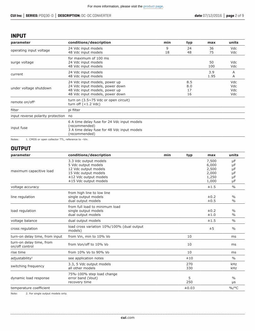
SOLDERABILITYparameter conditions/description min typ max units
wave soldering see wave soldering profile 260 °C
Tem
pera
ture
(°C)
Time (Seconds)
Notes: 1. Soldering materials: Sn/Cu/Ni 2. Ramp up rate during preheat: 1.4°C/s (from 50°C to 100°C) 3. Soaking temperature: 0.5°C/s (from 100°C to 130°C), 60±20 seconds 4. Peak temperature: 260°C, above 250°C for 3~6 seconds 5. Ramp down rate during cooling: -10°C/s (from 260°C to 150°C)
For more information, please visit the product page.
cui.com
date 07/12/2016 page 4 of 9CUI Inc SERIES: PDQ30-D DESCRIPTION: DC-DC CONVERTER
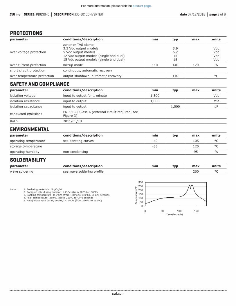
MECHANICALparameter conditions/description min typ max units
dimensions 1.00 x 1.00 x 0.4 [25.4 x 25.4 x 10.2 mm] inches
case material black coated copper with non-conductive base
weight 18 g
12
5 4 3
1.00
[25.
4]
1.00[25.4]
0.10
[2.5
]0.
800
[20.
32]
0.400[10.16]
0.400[10.16]
0.40 [10.2]
0.200[5.08]
0.40[10.2]
0.22 [5.6]
0.04
[1.0
]
min.
6
0.300[7.62]
Recommended PCB LayoutTop View
units: inches [mm]tolerance: X.XX ±0.02 [±0.5] X.XXX ±0.010 [±0.25]pin diameter tolerance: ±0.004[±0.1]
PIN CONNECTIONS
PINFunction
Single Dual
1 +Vin +Vin
2 -Vin -Vin
3 +Vout +Vout
4 Trim Common
5 -Vout -Vout
6 Remote Remote
MECHANICAL DRAWING
For more information, please visit the product page.
cui.com
date 07/12/2016 page 5 of 9CUI Inc SERIES: PDQ30-D DESCRIPTION: DC-DC CONVERTER
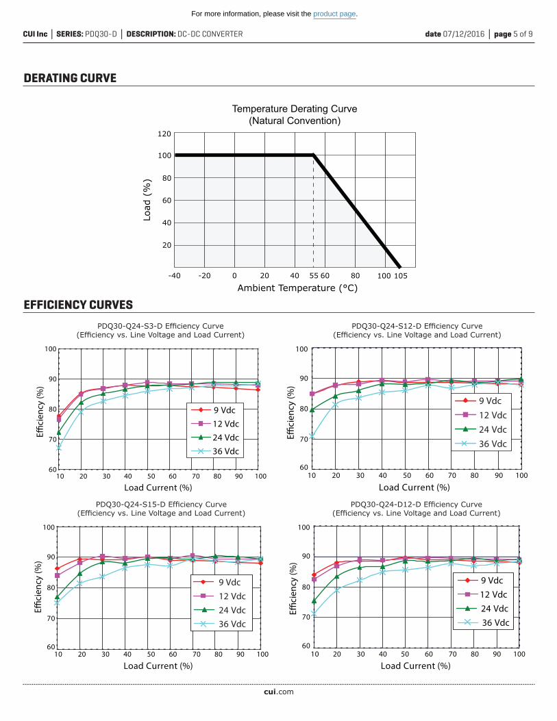
DERATING CURVE
Ambient Temperature (°C)
Load
(%
)
-40
60
80
100
40
20
-20 0 20 40 60 80
Temperature Derating Curve(Natural Convention)
120
10055 105
60
70
80
90
100
Eci
ency
(%)
9 Vdc12 Vdc24 Vdc36 Vdc
Load Current (%)10 20 30 40 50 60 70 80 90 100
EFFICIENCY CURVESPDQ30-Q24-S3-D Efficiency Curve
(Efficiency vs. Line Voltage and Load Current)
9 Vdc12 Vdc24 Vdc36 Vdc
Load Current (%)10 20 30 40 50 60 70 80 90 100
60
70
80
90
100
Eci
ency
(%)
PDQ30-Q24-S15-D Efficiency Curve(Efficiency vs. Line Voltage and Load Current)
9 Vdc12 Vdc24 Vdc36 Vdc
60
70
80
90
100
Eci
ency
(%)
Load Current (%)10 20 30 40 50 60 70 80 90 100
PDQ30-Q24-S12-D Efficiency Curve(Efficiency vs. Line Voltage and Load Current)
9 Vdc12 Vdc24 Vdc36 Vdc
60
70
80
90
100
Eci
ency
(%)
Load Current (%)10 20 30 40 50 60 70 80 90 100
PDQ30-Q24-D12-D Efficiency Curve(Efficiency vs. Line Voltage and Load Current)
For more information, please visit the product page.
cui.com
date 07/12/2016 page 6 of 9CUI Inc SERIES: PDQ30-D DESCRIPTION: DC-DC CONVERTER
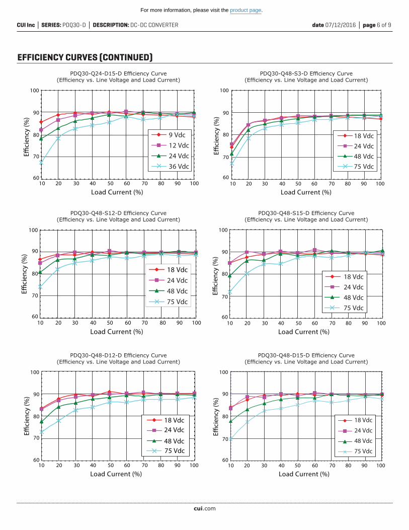
EFFICIENCY CURVES (CONTINUED)
18 Vdc
24 Vdc
48 Vdc
75 Vdc60
70
80
90
100
Eci
ency
(%)
Load Current (%)10 20 30 40 50 60 70 80 90 100
PDQ30-Q48-D15-D Efficiency Curve(Efficiency vs. Line Voltage and Load Current)
18 Vdc24 Vdc
48 Vdc75 Vdc
60
70
80
90
100
Eci
ency
(%)
Load Current (%)10 20 30 40 50 60 70 80 90 100
PDQ30-Q48-D12-D Efficiency Curve(Efficiency vs. Line Voltage and Load Current)
18 Vdc24 Vdc48 Vdc75 Vdc
60
70
80
90
100
Eci
ency
(%)
Load Current (%)10 20 30 40 50 60 70 80 90 100
PDQ30-Q48-S12-D Efficiency Curve(Efficiency vs. Line Voltage and Load Current)
18 Vdc24 Vdc48 Vdc75 Vdc
60
70
80
90
100
Eci
ency
(%)
Load Current (%)10 20 30 40 50 60 70 80 90 100
PDQ30-Q48-S15-D Efficiency Curve(Efficiency vs. Line Voltage and Load Current)
18 Vdc24 Vdc48 Vdc75 Vdc
60
70
80
90
100
Eci
ency
(%)
Load Current (%)10 20 30 40 50 60 70 80 90 100
PDQ30-Q48-S3-D Efficiency Curve(Efficiency vs. Line Voltage and Load Current)
9 Vdc12 Vdc24 Vdc36 Vdc
60
70
80
90
100
Eci
ency
(%)
Load Current (%)10 20 30 40 50 60 70 80 90 100
PDQ30-Q24-D15-D Efficiency Curve(Efficiency vs. Line Voltage and Load Current)
For more information, please visit the product page.
cui.com
date 07/12/2016 page 7 of 9CUI Inc SERIES: PDQ30-D DESCRIPTION: DC-DC CONVERTER
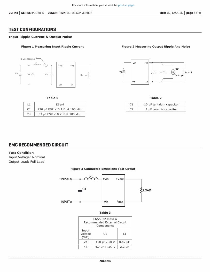
TEST CONFIGURATIONSInput Ripple Current & Output Noise
Figure 1 Measuring Input Ripple Current
Table 1
L1 12 µH
C1 220 µF ESR < 0.1 Ω at 100 kHz
Cin 33 µF ESR < 0.7 Ω at 100 kHz
C1 Cin
L1
To Oscilloscope
+Vin
-Vin
+Vo
-Vo
R-LoadVin
+
-
Figure 2 Measuring Output Ripple And Noise
Table 2
C1 10 µF tantalum capacitor
C2 1 µF ceramic capacitor
EMC RECOMMENDED CIRCUIT
Table 3
Figure 3 Conducted Emissions Test Circuit
EN55022 Class ARecommended External Circuit
Components
Input Voltage (Vdc)
C1 L1
24 100 µF / 50 V 0.47 µH
48 4.7 µF / 100 V 2.2 µH
Test ConditionInput Voltage: NominalOutput Load: Full Load
For more information, please visit the product page.
cui.com
date 07/12/2016 page 8 of 9CUI Inc SERIES: PDQ30-D DESCRIPTION: DC-DC CONVERTER
Table 4
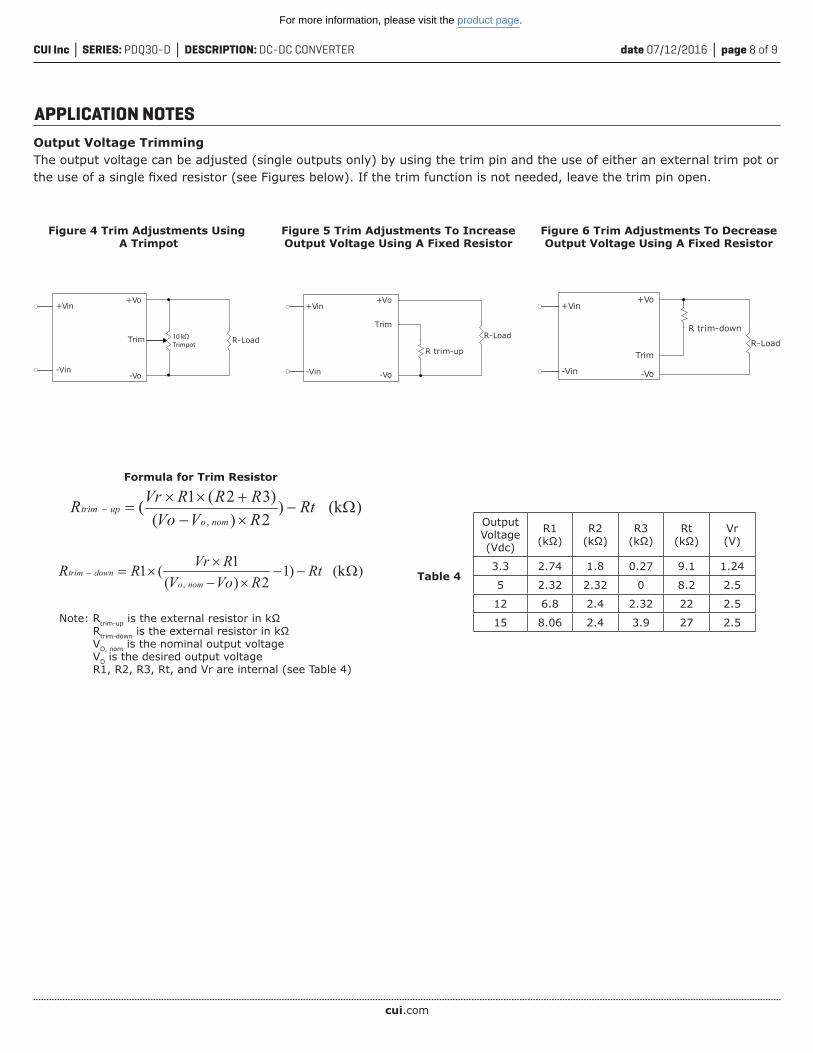
Output Voltage TrimmingThe output voltage can be adjusted (single outputs only) by using the trim pin and the use of either an external trim pot or the use of a single fixed resistor (see Figures below). If the trim function is not needed, leave the trim pin open.
APPLICATION NOTES
)(k)12)(
1(1,
RtRVoV
RVrRRnomo
downtrim
)(k)2)()32(1(
,Rt
RVVoRRRVrR
nomouptrim
Output Voltage (Vdc)
R1(kΩ)
R2(kΩ)
R3(kΩ)
Rt(kΩ)
Vr(V)
3.3 2.74 1.8 0.27 9.1 1.24
5 2.32 2.32 0 8.2 2.5
12 6.8 2.4 2.32 22 2.5
15 8.06 2.4 3.9 27 2.5Note: Rtrim-up is the external resistor in kΩ Rtrim-down is the external resistor in kΩ VO, nom is the nominal output voltage VO is the desired output voltage R1, R2, R3, Rt, and Vr are internal (see Table 4)
Formula for Trim Resistor
+Vin
-Vin-Vo
+Vo
R-LoadTrim 10 kΩTrimpot
+Vin
-Vin -Vo
+Vo
R trim-down
R-LoadTrim
Figure 5 Trim Adjustments To Increase Output Voltage Using A Fixed Resistor
+Vin
R trim-up
R-LoadTrim
+Vo
-Vin -Vo
Figure 4 Trim Adjustments Using A Trimpot
Figure 6 Trim Adjustments To Decrease Output Voltage Using A Fixed Resistor
For more information, please visit the product page.
date 07/12/2016 page 9 of 9CUI Inc SERIES: PDQ30-D DESCRIPTION: DC-DC CONVERTER
CUI offers a two (2) year limited warranty. Complete warranty information is listed on our website.
CUI reserves the right to make changes to the product at any time without notice. Information provided by CUI is believed to be accurate and reliable. However, no responsibility is assumed by CUI for its use, nor for any infringements of patents or other rights of third parties which may result from its use.
CUI products are not authorized or warranted for use as critical components in equipment that requires an extremely high level of reliability. A critical component is any component of a life support device or system whose failure to perform can be reasonably expected to cause the failure of the life support device or system, or to affect its safety or effectiveness.
Headquarters20050 SW 112th Ave.Tualatin, OR 97062800.275.4899
rev. description date
1.0 initial release 07/12/2016The revision history provided is for informational purposes only and is believed to be accurate.
REVISION HISTORY
For more information, please visit the product page.
Mouser Electronics
Authorized Distributor
Click to View Pricing, Inventory, Delivery & Lifecycle Information: CUI Inc.:
PDQ30-Q24-S15-D PDQ30-Q24-S3-D PDQ30-Q24-D12-D PDQ30-Q24-S12-D PDQ30-Q48-S15-D PDQ30-Q48-
S12-D PDQ30-Q48-S5-D PDQ30-Q24-D15-D PDQ30-Q48-D15-D PDQ30-Q48-D12-D PDQ30-Q48-S3-D PDQ30-
Q24-S5-D


![&Rbolg/ d o d &oì£lno 0b DC TV DLTV tu non. q] 8 · &Rbolg/ d o d &oì£lno 0b DC TV DLTV tu non. q] 8.9](https://img.pdfslide.us/doc/110x75/5fcfa0da92863413470208e6/rbolg-d-o-d-olno-0b-dc-tv-dltv-tu-non-q-8-rbolg-d-o-d-olno.jpg)