Embed Size (px)
Citation preview
www.murata-ps.com
www.murata-ps.com/support
For full details go towww.murata-ps.com/rohs
IRS SeriesEncapsulated Sixteenth-Brick DOSA-Compatible,
Wide Input Isolated DC-DC Converters
SDC_IRS Series.A01.D02 Page 1 of 26
FEATURES High efficiency synchronous flyback topology
18-75 Volts DC wide input range with 3.3, 5 and 12 Volts for Output voltage
Up to 54 Watts total output power with over-temperature shutdown
Tiny 1.44" x 1.04" x 0.50" baseplate package
Industry standard DOSA "brick" format and pinout
Extensive self-protection shut down features
Small footprint DC-DC converter, ideal for high current applications
2250 Volt Basic input/output isolation (48V models)
Operating temperature range -40 to +85°C with derating
Stable no-load operation with no required exter-nal components
Certified to UL 60950-1, 2nd Edition, EN60950-1 safety approvals
The world of “brick” DC-DC converters has seen a steady size reduction. The IRS series makes another dramatic size shrink down to a “sixteenth-brick” width (0.90 inches) while still retaining a high power output and full 2250 Volt DC isolation. The PC-board mount converter family accepts 18 to 75 Volts DC inputs and delivers fixed outputs regulated to within ±0.125%. The IRS converters are ideal for datacom and telecom applications, cell phone towers, data centers, server farms and network repeaters.
IRS outputs may be trimmed while delivering fast settling to current step loads and no adverse effects from higher capacitive loads. Excellent ripple and noise specifications assure compatibility to circuits using CPU’s, ASIC’s, programmable logic and
FPGA’s. No minimum load is required. For systems requiring controlled startup/shutdown, an external remote On/Off control may use a switch, transistor or digital logic.
Many self-protection features on the IRS series avoid both converter and external circuit hazards. These include input undervoltage lockout and overtemperature shutdown. The output of these DC-DC converters have current limit using the “hiccup” autorestart technique and the outputs may be short-circuited indefinitely. Additional features include output overvoltage and reverse conduction elimination.
The synchronous flyback topology yields high efficiency for minimal heat buildup and “no fan” operation.
PRODUCT OVERVIEW
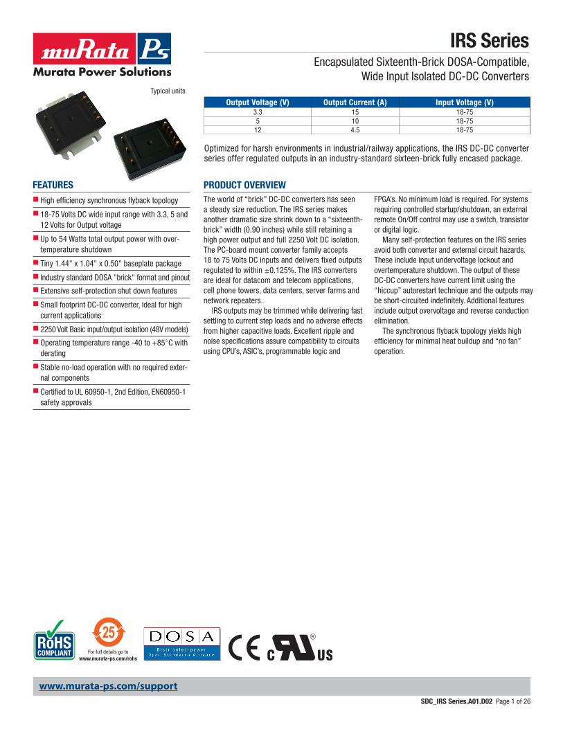
Typical units
Output Voltage (V) Output Current (A) Input Voltage (V)3.3 15 18-755 10 18-7512 4.5 18-75
Optimized for harsh environments in industrial/railway applications, the IRS DC-DC converter series offer regulated outputs in an industry-standard sixteen-brick fully encased package.
www.murata-ps.com/support
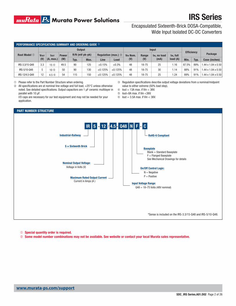
PART NUMBER STRUCTURE
*Sense is included on the IRS-3.3/15-Q48 and IRS-5/10-Q48.
IRS SeriesEncapsulated Sixteenth-Brick DOSA-Compatible,
Wide Input Isolated DC-DC Converters
SDC_IRS Series.A01.D02 Page 2 of 26
Maximum Rated Output Current Current in Amps (A )
S = Sixteenth Brick
Industrial-Railway
SIR - / -12 4.5 N
On/Off Control Logic: N = Negative P = Positive
➀ Please refer to the Part Number Structure when ordering.➁ All specifications are at nominal line voltage and full load, +25°C unless otherwise
noted. See detailed specifications. Output capacitors are 1 μF ceramic multilayer in parallel with 10 μF. I/O caps are necessary for our test equipment and may not be needed for your application.
➂ Regulation specifications describe output voltage deviations from a nominal/midpoint value to either extreme (50% load step).
➃ Iout = 13A max. if Vin < 36V.➄ Iout=8A max. if Vin <36V.➅ Iout = 3.5A max. if Vin < 36V.
C
RoHS-6 Compliant
-
Input Voltage Range: Q48 = 18–75 Volts (48V nominal)
Nominal Output Voltage: Voltage in Volts (V)
PERFORMANCE SPECIFICATIONS SUMMARY AND ORDERING GUIDE
Root Model ➀
Output InputEfficiency
PackageVout
(V)Iout
(A, max.)Power
(W)R/N (mV pk-pk) Regulation (max.) ➂ Vin Nom.
(V)Range
(V)Iin, no load
(mA)Iin, full
load (A)Typ. Max. Line Load Min. Typ. Case (inches)
IRS-3.3/15-Q48 3.3 15 ➃ 49.5 90 125 ±0.15% ±0.3% 48 18-75 25 1.16 87.5% 89% 1.44 x 1.04 x 0.50
IRS-5/10-Q48 5 10 ➄ 50 90 130 ±0.125% ±0.125% 48 18-75 30 1.14 88% 91% 1.44 x 1.04 x 0.50
IRS-12/4.5-Q48 12 4.5 ➅ 54 115 150 ±0.125% ±0.125% 48 18-75 25 1.24 89% 91% 1.44 x 1.04 x 0.50
Q48 F
Baseplate Blank = Standard Baseplate F = Flanged Baseplate See Mechanical Drawings for details
➀ Special quantity order is required.➁ Some model number combinations may not be available. See website or contact your local Murata sales representative.
www.murata-ps.com/support
IRS SeriesEncapsulated Sixteenth-Brick DOSA-Compatible,
Wide Input Isolated DC-DC Converters
SDC_IRS Series.A01.D02 Page 3 of 26
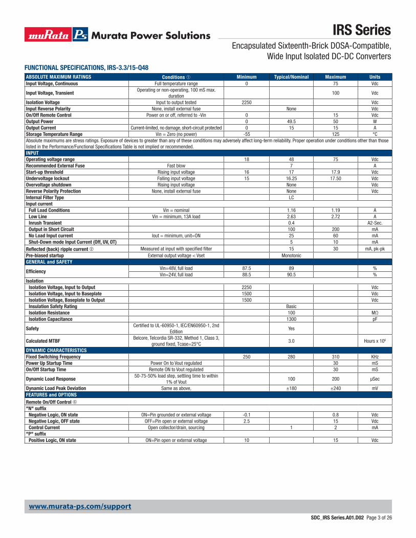
FUNCTIONAL SPECIFICATIONS, IRS-3.3/15-Q48ABSOLUTE MAXIMUM RATINGS Conditions ➀ Minimum Typical/Nominal Maximum UnitsInput Voltage, Continuous Full temperature range 0 75 Vdc
Input Voltage, TransientOperating or non-operating, 100 mS max.
duration100 Vdc
Isolation Voltage Input to output tested 2250 VdcInput Reverse Polarity None, install external fuse None VdcOn/Off Remote Control Power on or off, referred to -Vin 0 15 VdcOutput Power 0 49.5 50 WOutput Current Current-limited, no damage, short-circuit protected 0 15 15 AStorage Temperature Range Vin = Zero (no power) -55 125 °CAbsolute maximums are stress ratings. Exposure of devices to greater than any of these conditions may adversely affect long-term reliability. Proper operation under conditions other than those listed in the Performance/Functional Specifications Table is not implied or recommended.INPUTOperating voltage range 18 48 75 VdcRecommended External Fuse Fast blow 7 AStart-up threshold Rising input voltage 16 17 17.9 VdcUndervoltage lockout Falling input voltage 15 16.25 17.50 VdcOvervoltage shutdown Rising input voltage None VdcReverse Polarity Protection None, install external fuse None VdcInternal Filter Type LCInput current
Full Load Conditions Vin = nominal 1.16 1.19 ALow Line Vin = minimum, 13A load 2.63 2.72 AInrush Transient 0.4 A2-Sec.Output in Short Circuit 100 200 mANo Load Input current Iout = minimum, unit=ON 25 60 mAShut-Down mode Input Current (Off, UV, OT) 5 10 mA
Reflected (back) ripple current ➁ Measured at input with specified filter 15 30 mA, pk-pkPre-biased startup External output voltage < Vset MonotonicGENERAL and SAFETY
EfficiencyVin=48V, full load 87.5 89 %Vin=24V, full load 88.5 90.5 %
IsolationIsolation Voltage, Input to Output 2250 VdcIsolation Voltage, Input to Baseplate 1500 VdcIsolation Voltage, Baseplate to Output 1500 VdcInsulation Safety Rating BasicIsolation Resistance 100 MΩIsolation Capacitance 1300 pF
SafetyCertified to UL-60950-1, IEC/EN60950-1, 2nd
EditionYes
Calculated MTBFBelcore, Telcordia SR-332, Method 1, Class 3,
ground fixed, Tcase=25°C3.0 Hours x 106
DYNAMIC CHARACTERISTICSFixed Switching Frequency 250 280 310 KHzPower Up Startup Time Power On to Vout regulated 30 mSOn/Off Startup Time Remote ON to Vout regulated 30 mS
Dynamic Load Response50-75-50% load step, settling time to within
1% of Vout100 200 µSec
Dynamic Load Peak Deviation Same as above, ±180 ±240 mVFEATURES and OPTIONSRemote On/Off Control ➅"N" suffix
Negative Logic, ON state ON=Pin grounded or external voltage -0.1 0.8 VdcNegative Logic, OFF state OFF=Pin open or external voltage 2.5 15 VdcControl Current Open collector/drain, sourcing 1 2 mA
"P" suffixPositive Logic, ON state ON=Pin open or external voltage 10 15 Vdc
www.murata-ps.com/support
IRS SeriesEncapsulated Sixteenth-Brick DOSA-Compatible,
Wide Input Isolated DC-DC Converters
SDC_IRS Series.A01.D02 Page 4 of 26
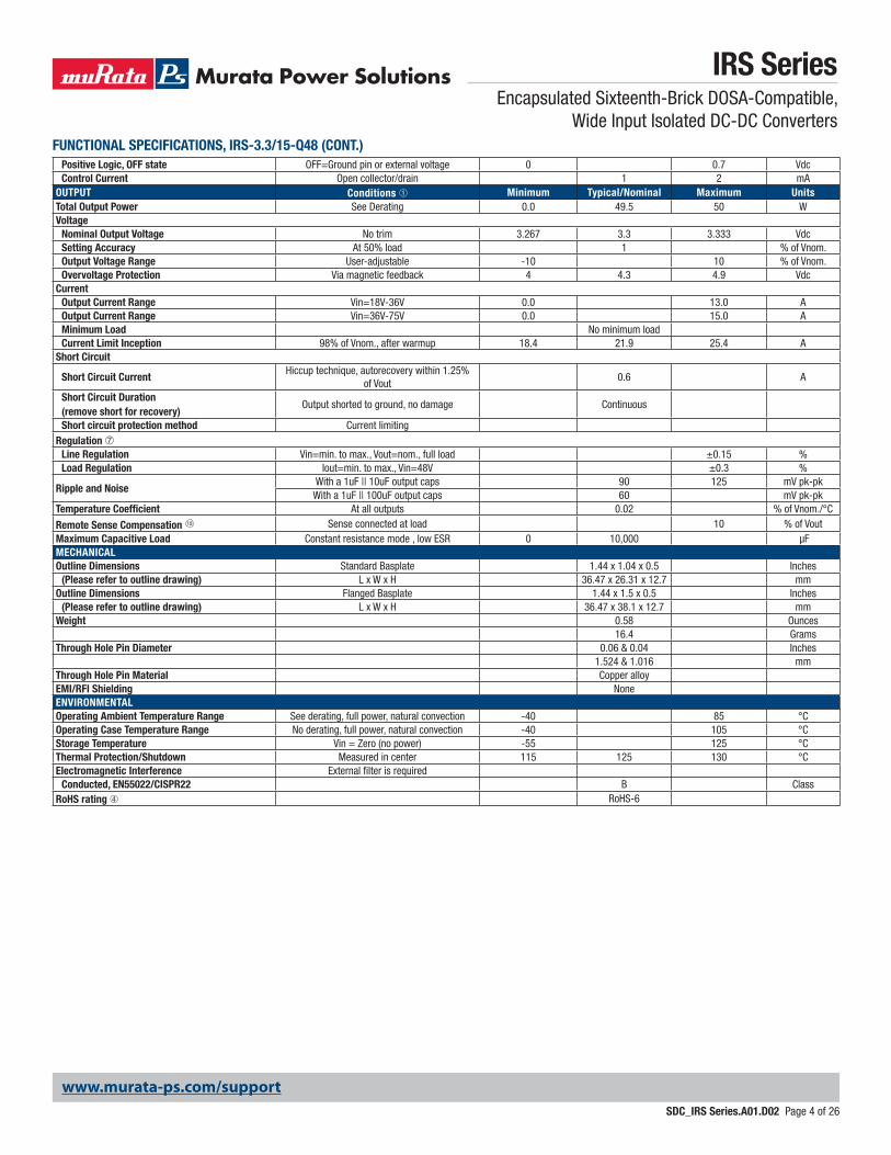
Positive Logic, OFF state OFF=Ground pin or external voltage 0 0.7 VdcControl Current Open collector/drain 1 2 mA
OUTPUT Conditions ➀ Minimum Typical/Nominal Maximum UnitsTotal Output Power See Derating 0.0 49.5 50 WVoltage
Nominal Output Voltage No trim 3.267 3.3 3.333 VdcSetting Accuracy At 50% load 1 % of Vnom.Output Voltage Range User-adjustable -10 10 % of Vnom.Overvoltage Protection Via magnetic feedback 4 4.3 4.9 Vdc
CurrentOutput Current Range Vin=18V-36V 0.0 13.0 AOutput Current Range Vin=36V-75V 0.0 15.0 AMinimum Load No minimum loadCurrent Limit Inception 98% of Vnom., after warmup 18.4 21.9 25.4 A
Short Circuit
Short Circuit CurrentHiccup technique, autorecovery within 1.25%
of Vout0.6 A
Short Circuit Duration (remove short for recovery)
Output shorted to ground, no damage Continuous
Short circuit protection method Current limitingRegulation ➆
Line Regulation Vin=min. to max., Vout=nom., full load ±0.15 %Load Regulation Iout=min. to max., Vin=48V ±0.3 %
Ripple and Noise With a 1uF || 10uF output caps 90 125 mV pk-pk
With a 1uF || 100uF output caps 60 mV pk-pkTemperature Coefficient At all outputs 0.02 % of Vnom./°C
Remote Sense Compensation 18 Sense connected at load 10 % of VoutMaximum Capacitive Load Constant resistance mode , low ESR 0 10,000 μFMECHANICALOutline Dimensions Standard Basplate 1.44 x 1.04 x 0.5 Inches
(Please refer to outline drawing) L x W x H 36.47 x 26.31 x 12.7 mmOutline Dimensions Flanged Basplate 1.44 x 1.5 x 0.5 Inches
(Please refer to outline drawing) L x W x H 36.47 x 38.1 x 12.7 mmWeight 0.58 Ounces
16.4 GramsThrough Hole Pin Diameter 0.06 & 0.04 Inches
1.524 & 1.016 mmThrough Hole Pin Material Copper alloyEMI/RFI Shielding NoneENVIRONMENTALOperating Ambient Temperature Range See derating, full power, natural convection -40 85 °COperating Case Temperature Range No derating, full power, natural convection -40 105 °CStorage Temperature Vin = Zero (no power) -55 125 °CThermal Protection/Shutdown Measured in center 115 125 130 °CElectromagnetic Interference External filter is required
Conducted, EN55022/CISPR22 B ClassRoHS rating ➃ RoHS-6
FUNCTIONAL SPECIFICATIONS, IRS-3.3/15-Q48 (CONT.)
www.murata-ps.com/support
IRS SeriesEncapsulated Sixteenth-Brick DOSA-Compatible,
Wide Input Isolated DC-DC Converters
SDC_IRS Series.A01.D02 Page 5 of 26
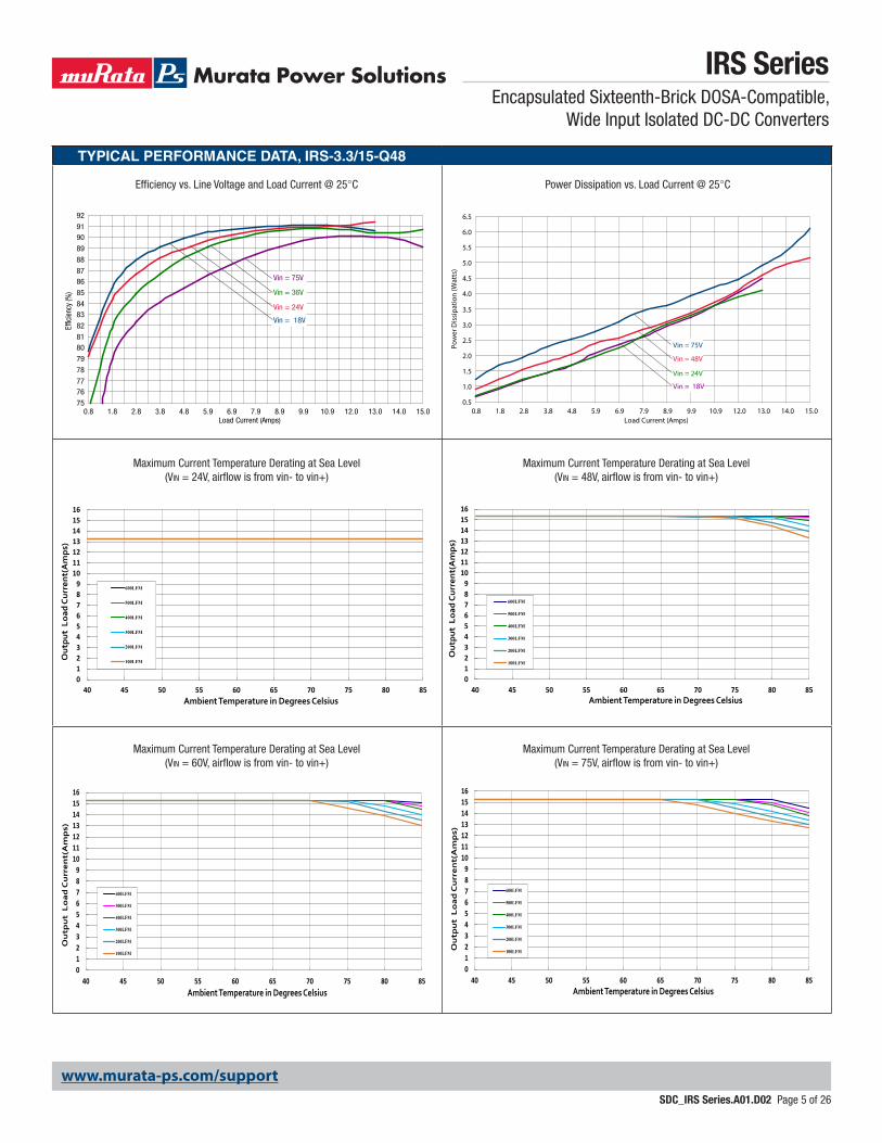
TYPICAL PERFORMANCE DATA, IRS-3.3/15-Q48
0.8 1.8 2.8 3.8 4.8 5.9 6.9 7.9 8.9 9.9 10.9 12.0 13.0 14.0 15.075
7677
78
79
8081
82
8384
85
8687
88
89
9091
92
Vin = 36V
Vin = 75V
Vin = 18V
Vin = 24V
Load Current (Amps)
Effic
ienc
y (%
)
Maximum Current Temperature Derating at Sea Level (Vin = 24V, airflow is from vin- to vin+)
Maximum Current Temperature Derating at Sea Level (Vin = 60V, airflow is from vin- to vin+)
Power Dissipation vs. Load Current @ 25°C
Maximum Current Temperature Derating at Sea Level (Vin = 48V, airflow is from vin- to vin+)
Maximum Current Temperature Derating at Sea Level (Vin = 75V, airflow is from vin- to vin+)
Efficiency vs. Line Voltage and Load Current @ 25°C
0.5
1.0
1.5
2.0
2.5
3.0
3.5
4.0
4.5
5.0
5.5
6.0
6.5
0.8 1.8 2.8 3.8 4.8 5.9 6.9 7.9 8.9 9.9 10.9 12.0 13.0 14.0 15.0
Vin = 48V
Vin = 75V
Vin = 18V
Vin = 24V
Load Current (Amps)
Pow
er D
issi
patio
n (W
atts
)
0123456789
10111213141516
40 45 50 55 60 65 70 75 80 85
Out
put
Lo
ad C
urre
nt(
Am
ps)
Ambient Temperature in Degrees Celsius
600LFM
500LFM
400LFM
300LFM
200LFM
100LFM
0123456789
10111213141516
40 45 50 55 60 65 70 75 80 85
Out
put
Lo
ad C
urre
nt(
Am
ps)
Ambient Temperature in Degrees Celsius
600LFM
500LFM
400LFM
300LFM
200LFM
100LFM
0123456789
10111213141516
40 45 50 55 60 65 70 75 80 85
Ou
tpu
t L
oa
d C
urr
en
t(A
mp
s)
Ambient Temperature in Degrees Celsius
600LFM
500LFM
400LFM
300LFM
200LFM
100LFM
0123456789
10111213141516
40 45 50 55 60 65 70 75 80 85
Ou
tpu
t L
oa
d C
urr
en
t(A
mp
s)
Ambient Temperature in Degrees Celsius
600LFM
500LFM
400LFM
300LFM
200LFM
100LFM
www.murata-ps.com/support
IRS SeriesEncapsulated Sixteenth-Brick DOSA-Compatible,
Wide Input Isolated DC-DC Converters
SDC_IRS Series.A01.D02 Page 6 of 26
TYPICAL PERFORMANCE DATA, IRS-3.3/15-Q48
0
20
40
60
80
100
120
40 45 50 55 60 65 70 75 80 85 90 95 100 105
Out
put C
urre
nt (
% o
f Nom
inal
)
Baseplate Temperature in Degrees Celsius
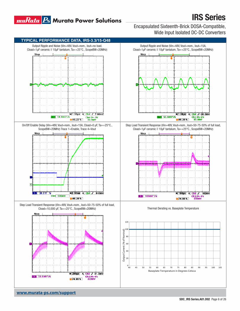
Output Ripple and Noise (Vin=48V, Vout=nom., Iout=no load, Cload=1µF ceramic || 10µF tantalum, Ta=+25°C., ScopeBW=20MHz)
Output Ripple and Noise (Vin=48V, Vout=nom., Iout=15A, Cload=1µF ceramic || 10µF tantalum, Ta=+25°C., ScopeBW=20MHz)
On/Off Enable Delay (Vin=48V, Vout=nom., Iout=15A, Cload=0 µF, Ta=+25°C., ScopeBW=20MHz) Trace 1=Enable, Trace 4=Vout
Step Load Transient Response (Vin=48V, Vout=nom., Iout=50-75-50% of full load, Cload=10,000 µF, Ta=+25°C., ScopeBW=20MHz)
Step Load Transient Response (Vin=48V, Vout=nom., Iout=50-75-50% of full load, Cload=1µF ceramic || 10µF tantalum, Ta=+25°C., ScopeBW=20MHz)
Thermal Derating vs. Baseplate Temperature
www.murata-ps.com/support
IRS SeriesEncapsulated Sixteenth-Brick DOSA-Compatible,
Wide Input Isolated DC-DC Converters
SDC_IRS Series.A01.D02 Page 7 of 26
FUNCTIONAL SPECIFICATIONS, IRS-5/10-Q48ABSOLUTE MAXIMUM RATINGS Conditions ➀ Minimum Typical/Nominal Maximum Units
Input Voltage, Continuous Full temperature range 0 75 Vdc
Input Voltage, TransientOperating or non-operating, tested:
100 mS max. duration0 100 Vdc
Isolation Voltage Input to output 2250 VdcInput Reverse Polarity None, install external fuse None VdcOn/Off Remote Control Power on, referred to -Vin 0 15 VdcOutput Power 0 50 50.63 WOutput Current Current-limited, no damage, short-circuit protected 0 10 10 AStorage Temperature Range Vin = Zero (no power) -55 125 °CAbsolute maximums are stress ratings. Exposure of devices to greater than any of these conditions may adversely affect long-term reliability. Proper operation under conditions other than those listed in the Performance/Functional Specifications Table is not implied or recommended.INPUTOperating voltage range 18 48 75 VdcRecommended External Fuse Fast blow 5 AStart-up threshold, turn on Rising input voltage 16 17.5 17.9 VdcUndervoltage shutdown, turn off Falling input voltage 15 16.75 17.5 VdcOvervoltage shutdown NA VdcReverse Polarity Protection None, install external fuse None VdcInternal Filter Type LCInput current
Full Load Conditions Vin = nominal 1.14 1.2 ALow Line Vin = minimum 2.44 2.51 AInrush Transient 0.4 A2-Sec.Output in Short Circuit 100 200 mANo Load Input Current Iout = minimum, unit=ON 30 60 mAShut-Down Mode Input Current 5 10 mA
Reflected (back) ripple current ➁ No filtering 150 200 mAp-p
Reflected (back) ripple current ➁ Measured at input with specified filter 15 30 mAp-pPre-biased startup External output voltage < Vset MonotonicGENERAL and SAFETY
EfficiencyVin=48V, full load 88 91 % Vin=24V, full load 89.5 91 %
IsolationIsolation Voltage, Input to Output 2250 VdcIsolation Voltage, Input to Baseplate 1500 VdcIsolation Voltage, Baseplate to Output 1500 VdcInsulation Safety Rating BasicIsolation Resistance 100 MΩIsolation Capacitance 1000 pF
Safety (meets the following requirements)UL-60950-1, CSA-C22.2 No.60950-1,
IEC/EN60950-1, 2nd EditionYes
Calculated MTBFBelcore, Telcordia SR-332, Method 1, class 3,
ground fixed, Tambient=25°C3.0 Hours x 106
DYNAMIC CHARACTERISTICSFixed Switching Frequency 225 275 325 KHzStartup Time Power On to Vout regulated 30 mSStartup Time Remote ON to Vout regulated 30 mS
Dynamic Load Response50-75-50% load step, settling time to within
1% of Vout100 200 µSec
Dynamic Load Peak Deviation Same as above, ±180 ±240 mVFEATURES and OPTIONSRemote On/Off Control ➅"N" suffix
Negative Logic, ON state ON = Pin grounded or external voltage -0.1 0.8 VNegative Logic, OFF state OFF = Pin open or external voltage 2.5 15 VControl Current open collector/drain 1 2 mA
"P" suffixPositive Logic, ON state ON = Pin open or external voltage 10 15 VPositive Logic, OFF state OFF = Ground pin or external voltage 0 0.7 VControl Current open collector/drain 1 2 mA
www.murata-ps.com/support
IRS SeriesEncapsulated Sixteenth-Brick DOSA-Compatible,
Wide Input Isolated DC-DC Converters
SDC_IRS Series.A01.D02 Page 8 of 26
OUTPUT Conditions ➀ Minimum Typical/Nominal Maximum UnitsTotal Output Power See Derating 0.0 50 50.63 WVoltage
Nominal Output Voltage No trim 4.938 5 5.063 VdcSetting Accuracy At 50% load -1.25 1.25 % of VsetOutput Voltage Range User-adjustable -20 10Overvoltage Protection Via magnetic feedback 6.2 6.4 6.6 Vdc
CurrentOutput Current Range Vin=18V to 36V 0 8Output Current Range Vin=36V to 75V 0 10 AMinimum Load No minimum loadCurrent Limit Inception 98% of Vnom., cold condition 12 14 16.5 A
Short Circuit
Short Circuit CurrentHiccup technique, autorecovery within
1.25% of Vout0.6 A
Short Circuit Duration (remove short for recovery)
Output shorted to ground, no damage Continuous
Short circuit protection method Current limitingRegulation ➆
Line Regulation Vin=min. to max., Vout=nom., nom load ±0.125 VLoad Regulation Iout=min. to max ±0.125 V
Ripple and Noise With a 1uF || 10 uF output caps. 90 130 mV pk-pk
With a 1uF || 100uF tantalum output caps 65 mV pk-pkTemperature Coefficient At all outputs 0.02 % of Vout./°CRemote Sense Compensation 18 Sense connected at load 10 % of VoutMaximum Capacitive Loading (10% ceramic,
90% Oscon)Constant resistance mode , low ESR 0 5000 μF
MECHANICALOutline Dimensions Standard Basplate 1.44 x 1.04 x 0.5 Inches
(Please refer to outline drawing) L x W x H 36.47 x 26.31 x 12.7 mmOutline Dimensions Flanged Basplate 1.44 x 1.5 x 0.5 Inches
(Please refer to outline drawing) L x W x H 36.47 x 38.1 x 12.7 mmWeight 0.58 Ounces
16.4 GramsThrough Hole Pin Diameter Diameter of pins standard 0.06 & 0.04 Inches
1.524 & 1.016 mm
Through Hole Pin MaterialGold-plated copper
alloy with nickel underplate
TH Pin Plating Metal and Thickness Nickel subplate 50 µ-inchesGold overplate 5 µ-inches
EMI/RFI Shielding NoneENVIRONMENTALOperating Ambient Temperature Range See derating curves -40 85 °CStorage Temperature Vin = Zero (no power) -55 125 °COperating Case Temp No derating required -40 105 °CThermal Protection/Shutdown Measured at hotspot 115 125 130 °CElectromagnetic Interference External filter is required
Conducted, EN55022/CISPR22 B ClassRoHS rating ➃ RoHS-6
FUNCTIONAL SPECIFICATIONS, IRS-5/10-Q48 (CONT.)
19
www.murata-ps.com/support
IRS SeriesEncapsulated Sixteenth-Brick DOSA-Compatible,
Wide Input Isolated DC-DC Converters
SDC_IRS Series.A01.D02 Page 9 of 26
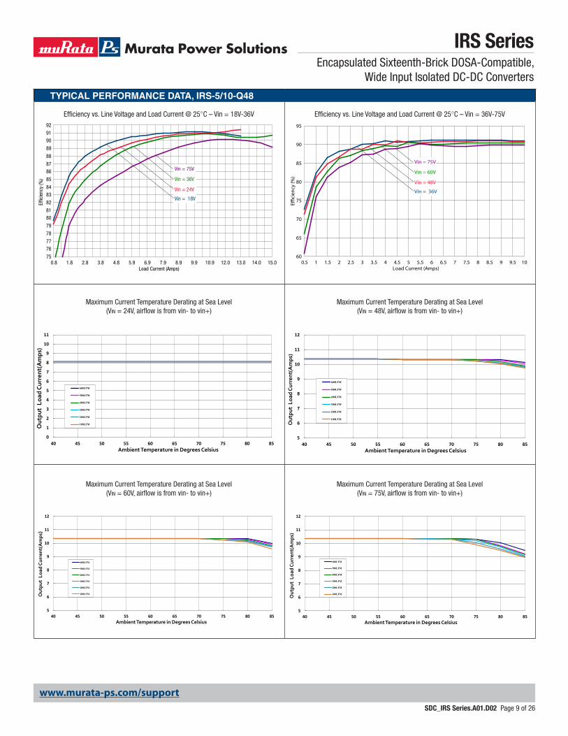
TYPICAL PERFORMANCE DATA, IRS-5/10-Q48
Maximum Current Temperature Derating at Sea Level (Vin = 24V, airflow is from vin- to vin+)
Maximum Current Temperature Derating at Sea Level (Vin = 60V, airflow is from vin- to vin+)
Maximum Current Temperature Derating at Sea Level (Vin = 48V, airflow is from vin- to vin+)
Maximum Current Temperature Derating at Sea Level (Vin = 75V, airflow is from vin- to vin+)
Efficiency vs. Line Voltage and Load Current @ 25°C – Vin = 36V-75VEfficiency vs. Line Voltage and Load Current @ 25°C – Vin = 18V-36V
60
65
70
75
80
85
90
95
0.5 1 1.5 2 2.5 3 3.5 4 4.5 5 5.5 6 6.5 7 7.5 8 8.5 9 9.5 10
Vin = 60V
Vin = 75V
Vin = 36V
Vin = 48V
Load Current (Amps)
Eci
ency
(%)
0
1
2
3
4
5
6
7
8
9
10
11
40 45 50 55 60 65 70 75 80 85
Out
put
Loa
d Cu
rren
t(A
mps
)
Ambient Temperature in Degrees Celsius
600LFM
500LFM
400LFM
300LFM
200LFM
100LFM
5
6
7
8
9
10
11
12
40 45 50 55 60 65 70 75 80 85
Out
put
Load
Cur
rent
(Am
ps)
Ambient Temperature in Degrees Celsius
600LFM
500LFM
400LFM
300LFM
200LFM
100LFM
5
6
7
8
9
10
11
12
40 45 50 55 60 65 70 75 80 85
Out
put
Load
Cur
rent
(Am
ps)
Ambient Temperature in Degrees Celsius
600LFM
500LFM
400LFM
300LFM
200LFM
100LFM
5
6
7
8
9
10
11
12
40 45 50 55 60 65 70 75 80 85
Out
put
Load
Cur
rent
(Am
ps)
Ambient Temperature in Degrees Celsius
600LFM
500LFM
400LFM
300LFM
200LFM
100LFM
0.8 1.8 2.8 3.8 4.8 5.9 6.9 7.9 8.9 9.9 10.9 12.0 13.0 14.0 15.075
7677
78
79
8081
82
8384
85
8687
88
89
9091
92
Vin = 36V
Vin = 75V
Vin = 18V
Vin = 24V
Load Current (Amps)
Effic
ienc
y (%
)
www.murata-ps.com/support
IRS SeriesEncapsulated Sixteenth-Brick DOSA-Compatible,
Wide Input Isolated DC-DC Converters
SDC_IRS Series.A01.D02 Page 10 of 26
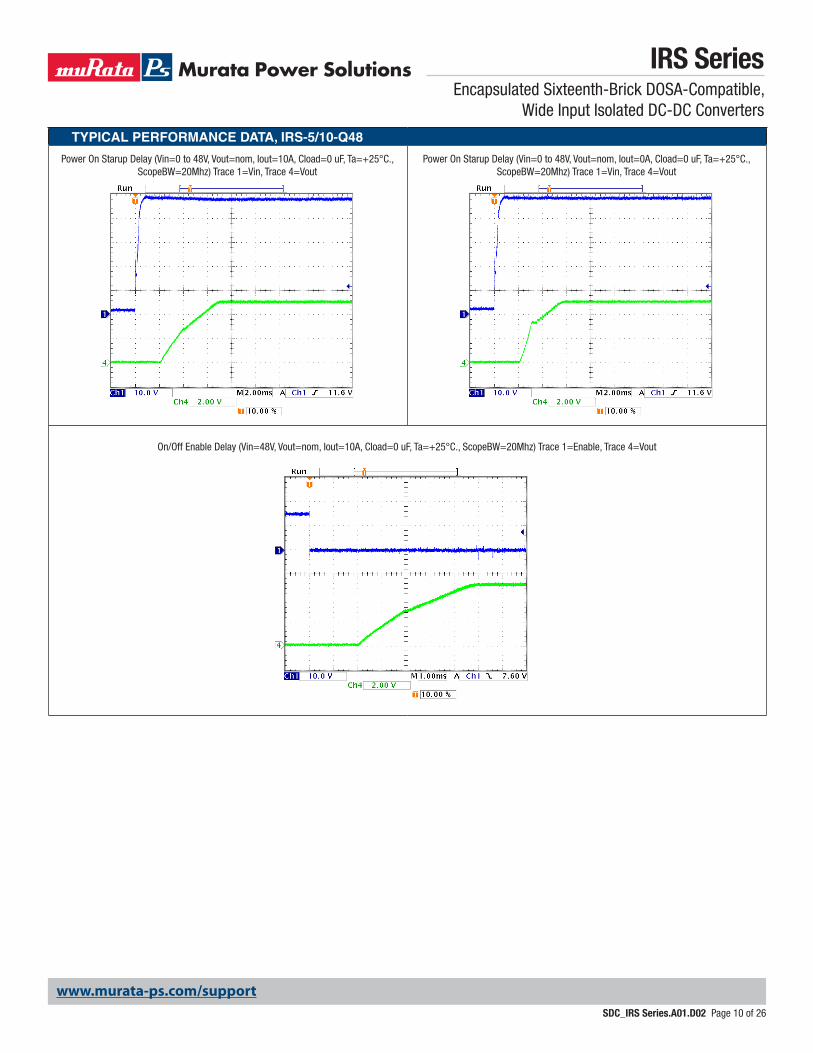
TYPICAL PERFORMANCE DATA, IRS-5/10-Q48
Power On Starup Delay (Vin=0 to 48V, Vout=nom, Iout=10A, Cload=0 uF, Ta=+25°C., ScopeBW=20Mhz) Trace 1=Vin, Trace 4=Vout
Power On Starup Delay (Vin=0 to 48V, Vout=nom, Iout=0A, Cload=0 uF, Ta=+25°C., ScopeBW=20Mhz) Trace 1=Vin, Trace 4=Vout
On/Off Enable Delay (Vin=48V, Vout=nom, Iout=10A, Cload=0 uF, Ta=+25°C., ScopeBW=20Mhz) Trace 1=Enable, Trace 4=Vout
www.murata-ps.com/support
IRS SeriesEncapsulated Sixteenth-Brick DOSA-Compatible,
Wide Input Isolated DC-DC Converters
SDC_IRS Series.A01.D02 Page 11 of 26
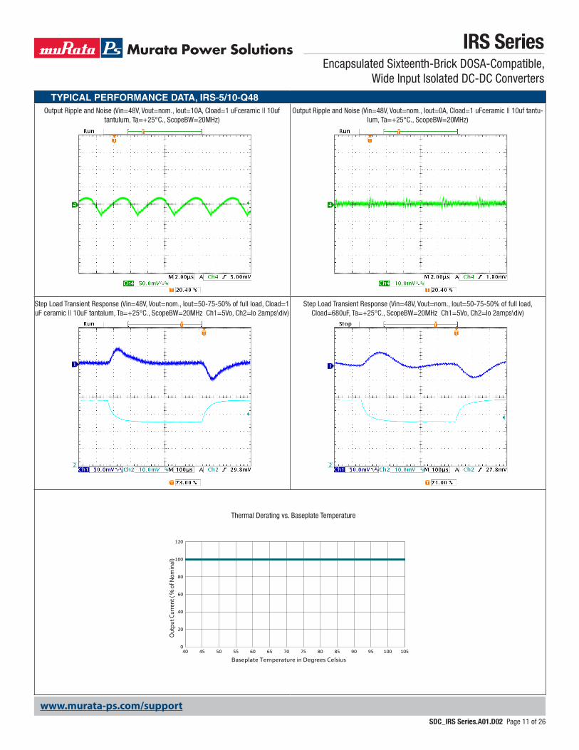
TYPICAL PERFORMANCE DATA, IRS-5/10-Q48Output Ripple and Noise (Vin=48V, Vout=nom., Iout=10A, Cload=1 uFceramic || 10uf
tantulum, Ta=+25°C., ScopeBW=20MHz)Output Ripple and Noise (Vin=48V, Vout=nom., Iout=0A, Cload=1 uFceramic || 10uf tantu-
lum, Ta=+25°C., ScopeBW=20MHz)
Step Load Transient Response (Vin=48V, Vout=nom., Iout=50-75-50% of full load, Cload=1 uF ceramic || 10uF tantalum, Ta=+25°C., ScopeBW=20MHz Ch1=5Vo, Ch2=Io 2amps\div)
Step Load Transient Response (Vin=48V, Vout=nom., Iout=50-75-50% of full load, Cload=680uF, Ta=+25°C., ScopeBW=20MHz Ch1=5Vo, Ch2=Io 2amps\div)
Thermal Derating vs. Baseplate Temperature
0
20
40
60
80
100
120
40 45 50 55 60 65 70 75 80 85 90 95 100 105
Out
put C
urre
nt (
% o
f Nom
inal
)
Baseplate Temperature in Degrees Celsius
www.murata-ps.com/support
IRS SeriesEncapsulated Sixteenth-Brick DOSA-Compatible,
Wide Input Isolated DC-DC Converters
SDC_IRS Series.A01.D02 Page 12 of 26
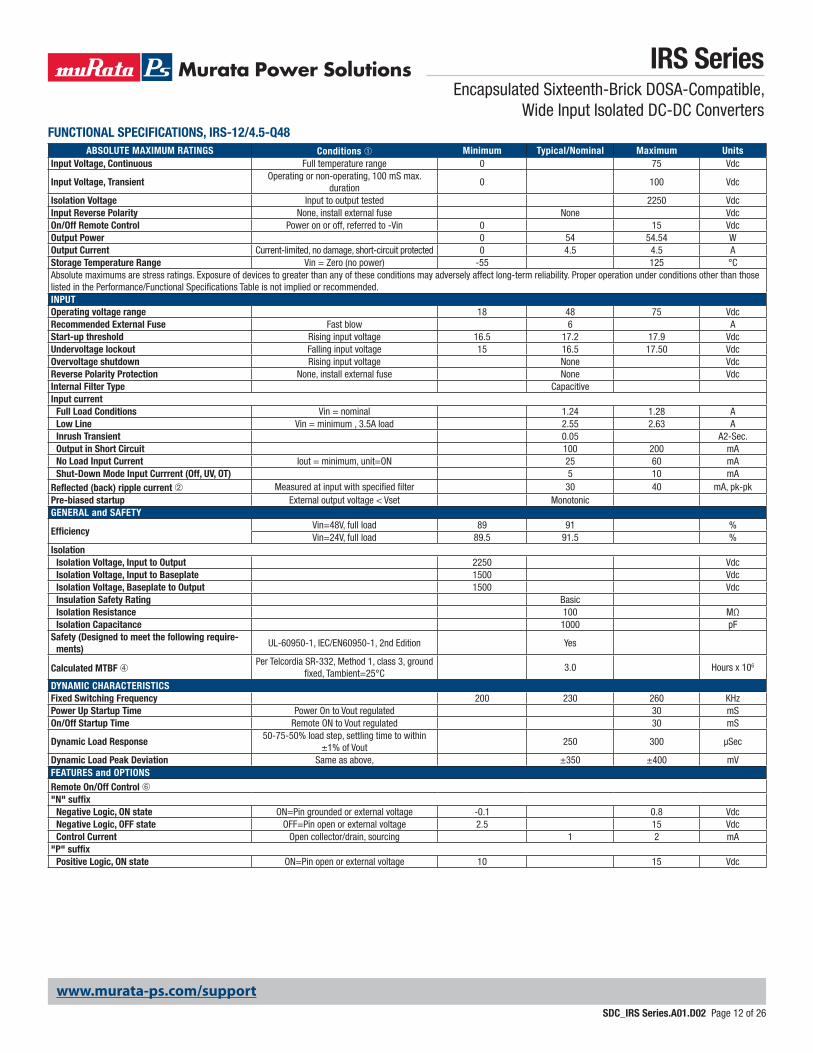
FUNCTIONAL SPECIFICATIONS, IRS-12/4.5-Q48ABSOLUTE MAXIMUM RATINGS Conditions ➀ Minimum Typical/Nominal Maximum Units
Input Voltage, Continuous Full temperature range 0 75 Vdc
Input Voltage, TransientOperating or non-operating, 100 mS max.
duration0 100 Vdc
Isolation Voltage Input to output tested 2250 VdcInput Reverse Polarity None, install external fuse None VdcOn/Off Remote Control Power on or off, referred to -Vin 0 15 VdcOutput Power 0 54 54.54 WOutput Current Current-limited, no damage, short-circuit protected 0 4.5 4.5 AStorage Temperature Range Vin = Zero (no power) -55 125 °CAbsolute maximums are stress ratings. Exposure of devices to greater than any of these conditions may adversely affect long-term reliability. Proper operation under conditions other than those listed in the Performance/Functional Specifications Table is not implied or recommended.INPUTOperating voltage range 18 48 75 VdcRecommended External Fuse Fast blow 6 AStart-up threshold Rising input voltage 16.5 17.2 17.9 VdcUndervoltage lockout Falling input voltage 15 16.5 17.50 VdcOvervoltage shutdown Rising input voltage None VdcReverse Polarity Protection None, install external fuse None VdcInternal Filter Type CapacitiveInput current
Full Load Conditions Vin = nominal 1.24 1.28 ALow Line Vin = minimum , 3.5A load 2.55 2.63 AInrush Transient 0.05 A2-Sec.Output in Short Circuit 100 200 mANo Load Input Current Iout = minimum, unit=ON 25 60 mAShut-Down Mode Input Currrent (Off, UV, OT) 5 10 mA
Reflected (back) ripple current ➁ Measured at input with specified filter 30 40 mA, pk-pkPre-biased startup External output voltage < Vset MonotonicGENERAL and SAFETY
EfficiencyVin=48V, full load 89 91 %Vin=24V, full load 89.5 91.5 %
IsolationIsolation Voltage, Input to Output 2250 VdcIsolation Voltage, Input to Baseplate 1500 VdcIsolation Voltage, Baseplate to Output 1500 VdcInsulation Safety Rating BasicIsolation Resistance 100 MΩIsolation Capacitance 1000 pF
Safety (Designed to meet the following require-ments)
UL-60950-1, IEC/EN60950-1, 2nd Edition Yes
Calculated MTBF ➃Per Telcordia SR-332, Method 1, class 3, ground
fixed, Tambient=25°C3.0 Hours x 106
DYNAMIC CHARACTERISTICSFixed Switching Frequency 200 230 260 KHzPower Up Startup Time Power On to Vout regulated 30 mSOn/Off Startup Time Remote ON to Vout regulated 30 mS
Dynamic Load Response50-75-50% load step, settling time to within
±1% of Vout250 300 µSec
Dynamic Load Peak Deviation Same as above, ±350 ±400 mVFEATURES and OPTIONSRemote On/Off Control ➅"N" suffix
Negative Logic, ON state ON=Pin grounded or external voltage -0.1 0.8 VdcNegative Logic, OFF state OFF=Pin open or external voltage 2.5 15 VdcControl Current Open collector/drain, sourcing 1 2 mA
"P" suffixPositive Logic, ON state ON=Pin open or external voltage 10 15 Vdc
www.murata-ps.com/support
IRS SeriesEncapsulated Sixteenth-Brick DOSA-Compatible,
Wide Input Isolated DC-DC Converters
SDC_IRS Series.A01.D02 Page 13 of 26
Positive Logic, OFF state OFF=Pin grounded or external voltage 0 0.7 VdcControl Current Open collector/drain, sinking 1 2 mA
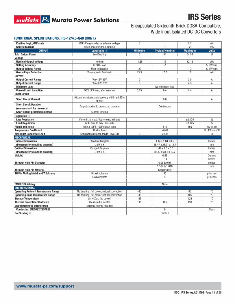
OUTPUT Conditions ➀ Minimum Typical/Nominal Maximum UnitsTotal Output Power See Derating 0 54 54.54 WVoltage
Nominal Output Voltage No trim 11.88 12 12.12 VdcSetting Accuracy At 50% load ±1 % of Vnom.Output Voltage Range User-adjustable -20 10 % of Vnom.Overvoltage Protection Via magnetic feedback 13.3 15.3 18 Vdc
CurrentOutput Current Range Vin=18V-36V 0 3.5 AOutput Current Range Vin=36V-75V 0 4.5 AMinimum Load No minimum loadCurrent Limit Inception 98% of Vnom., after warmup 5.05 6.4 7.4 A
Short Circuit
Short Circuit CurrentHiccup technique, autorecovery within ±1.25%
of Vout0.6 A
Short Circuit Duration (remove short for recovery)
Output shorted to ground, no damage Continuous
Short circuit protection method Current limitingRegulation ➆
Line Regulation Vin=min. to max., Vout=nom., full load ±0.125 %Load Regulation Iout=min. to max., Vin=48V ±0.125 %
Ripple and Noise with a 1uF || 10uF output caps 115 150 mV pk-pkTemperature Coefficient At all outputs ±0.02 % of Vnom./°CMaximum Capacitive Load Constant resistance mode , low ESR 0 2200 μFMECHANICALOutline Dimensions Standard Basplate 1.44 x 1.04 x 0.5 Inches
(Please refer to outline drawing) L x W x H 36.47 x 26.31 x 12.7 mmOutline Dimensions Flanged Basplate 1.44 x 1.5 x 0.5 Inches
(Please refer to outline drawing) L x W x H 36.47 x 38.1 x 12.7 mmWeight 0.58 Ounces
16.4 GramsThrough Hole Pin Diameter 0.06 & 0.04 Inches
1.524 & 1.016 mmThrough Hole Pin Material Copper alloyTH Pin Plating Metal and Thickness Nickel subplate 50 µ-inches
Gold overplate 5 µ-inches
EMI/RFI Shielding NoneENVIRONMENTALOperating Ambient Temperature Range No derating, full power, natural convection -40 85 °COperating Case Temperature Range No derating, full power, natural convection -40 105 °CStorage Temperature Vin = Zero (no power) -55 125 °CThermal Protection/Shutdown Measured in center 115 125 130 °CElectromagnetic Interference External filter is required
Conducted, EN55022/CISPR22 B ClassRoHS rating ➃ RoHS-6
FUNCTIONAL SPECIFICATIONS, IRS-12/4.5-Q48 (CONT.)
www.murata-ps.com/support
IRS SeriesEncapsulated Sixteenth-Brick DOSA-Compatible,
Wide Input Isolated DC-DC Converters
SDC_IRS Series.A01.D02 Page 14 of 26
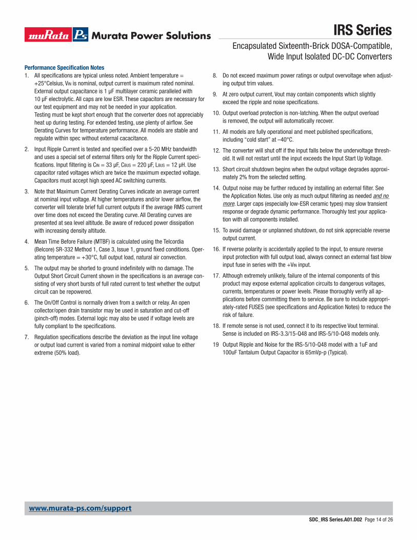
Performance Specification Notes1. All specifications are typical unless noted. Ambient temperature =
+25°Celsius, Vin is nominal, output current is maximum rated nominal. External output capacitance is 1 µF multilayer ceramic paralleled with 10 µF electrolytic. All caps are low ESR. These capacitors are necessary for our test equipment and may not be needed in your application.
Testing must be kept short enough that the converter does not appreciably heat up during testing. For extended testing, use plenty of airflow. See Derating Curves for temperature performance. All models are stable and regulate within spec without external cacacitance.
2. Input Ripple Current is tested and specified over a 5-20 MHz bandwidth and uses a special set of external filters only for the Ripple Current speci-fications. Input filtering is Cin = 33 µF, Cbus = 220 µF, Lbus = 12 µH. Use capacitor rated voltages which are twice the maximum expected voltage. Capacitors must accept high speed AC switching currents.
3. Note that Maximum Current Derating Curves indicate an average current at nominal input voltage. At higher temperatures and/or lower airflow, the converter will tolerate brief full current outputs if the average RMS current over time does not exceed the Derating curve. All Derating curves are presented at sea level altitude. Be aware of reduced power dissipation with increasing density altitude.
4. Mean Time Before Failure (MTBF) is calculated using the Telcordia (Belcore) SR-332 Method 1, Case 3, Issue 1, ground fixed conditions. Oper-ating temperature = +30°C, full output load, natural air convection.
5. The output may be shorted to ground indefinitely with no damage. The Output Short Circuit Current shown in the specifications is an average con-sisting of very short bursts of full rated current to test whether the output circuit can be repowered.
6. The On/Off Control is normally driven from a switch or relay. An open collector/open drain transistor may be used in saturation and cut-off (pinch-off) modes. External logic may also be used if voltage levels are fully compliant to the specifications.
7. Regulation specifications describe the deviation as the input line voltage or output load current is varied from a nominal midpoint value to either extreme (50% load).
8. Do not exceed maximum power ratings or output overvoltage when adjust-ing output trim values.
9. At zero output current, Vout may contain components which slightly exceed the ripple and noise specifications.
10. Output overload protection is non-latching. When the output overload is removed, the output will automatically recover.
11. All models are fully operational and meet published specifications, including “cold start” at –40°C.
12. The converter will shut off if the input falls below the undervoltage thresh-old. It will not restart until the input exceeds the Input Start Up Voltage.
13. Short circuit shutdown begins when the output voltage degrades approxi-mately 2% from the selected setting.
14. Output noise may be further reduced by installing an external filter. See the Application Notes. Use only as much output filtering as needed and no more. Larger caps (especially low-ESR ceramic types) may slow transient response or degrade dynamic performance. Thoroughly test your applica-tion with all components installed.
15. To avoid damage or unplanned shutdown, do not sink appreciable reverse output current.
16. If reverse polarity is accidentally applied to the input, to ensure reverse input protection with full output load, always connect an external fast blow input fuse in series with the +Vin input.
17. Although extremely unlikely, failure of the internal components of this product may expose external application circuits to dangerous voltages, currents, temperatures or power levels. Please thoroughly verify all ap-plications before committing them to service. Be sure to include appropri-ately-rated FUSES (see specifications and Application Notes) to reduce the risk of failure.
18. If remote sense is not used, connect it to its respective Vout terminal. Sense is included on IRS-3.3/15-Q48 and IRS-5/10-Q48 models only.
19 Output Ripple and Noise for the IRS-5/10-Q48 model with a 1uF and 100uF Tantalum Output Capacitor is 65mVp-p (Typical).
www.murata-ps.com/support
IRS SeriesEncapsulated Sixteenth-Brick DOSA-Compatible,
Wide Input Isolated DC-DC Converters
SDC_IRS Series.A01.D02 Page 15 of 26
TYPICAL PERFORMANCE DATA, IRS-12/4.5-Q48
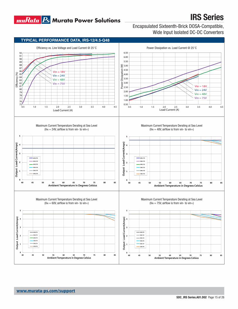
Efficiency vs. Line Voltage and Load Current @ 25°C
Maximum Current Temperature Derating at Sea Level (Vin = 24V, airflow is from vin- to vin+)
Maximum Current Temperature Derating at Sea Level (Vin = 60V, airflow is from vin- to vin+)
Power Dissipation vs. Load Current @ 25°C
Maximum Current Temperature Derating at Sea Level (Vin = 48V, airflow is from vin- to vin+)
Maximum Current Temperature Derating at Sea Level (Vin = 75V, airflow is from vin- to vin+)
757677787980818283848586878889909192
0.5 1.0 1.5 2.0 2.5 3.0 3.5 4.0 4.5Load Current (A)
Eci
ency
(%) Vin = 18V
Vin = 24VVin = 48VVin = 75V
0.50
1.00
1.50
2.00
2.50
3.00
3.50
4.00
4.50
5.00
5.50
6.00
6.50
0.5 1.0 1.5 2.0 2.5 3.0 3.5 4.0 4.5Load Current (A)
Pow
er D
issip
atio
n (W
)
Vin = 18VVin = 24VVin = 48VVin = 75V
0
1
2
3
4
5
40 45 50 55 60 65 70 75 80 85
Out
put
Loa
d Cu
rren
t(A
mps
)
Ambient Temperature in Degrees Celsius
600LFM
500LFM
400LFM
300LFM
200LFM
100LFM
0
1
2
3
4
5
40 45 50 55 60 65 70 75 80 85
Out
put
Loa
d Cu
rren
t(A
mps
)
Ambient Temperature in Degrees Celsius
600LFM
500LFM
400LFM
300LFM
200LFM
100LFM
0
1
2
3
4
5
40 45 50 55 60 65 70 75 80 85
Out
put
Lo
ad C
urre
nt(
Am
ps)
Ambient Temperature in Degrees Celsius
600LFM
500LFM
400LFM
300LFM
200LFM
100LFM
0
1
2
3
4
5
40 45 50 55 60 65 70 75 80 85
Out
put
Loa
d C
urre
nt(A
mps
)
Ambient Temperature in Degrees Celsius
600LFM
500LFM
400LFM
300LFM
200LFM
100LFM
www.murata-ps.com/support
IRS SeriesEncapsulated Sixteenth-Brick DOSA-Compatible,
Wide Input Isolated DC-DC Converters
SDC_IRS Series.A01.D02 Page 16 of 26
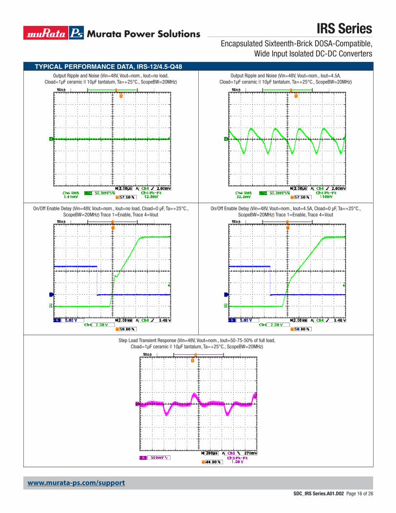
TYPICAL PERFORMANCE DATA, IRS-12/4.5-Q48Output Ripple and Noise (Vin=48V, Vout=nom., Iout=no load,
Cload=1µF ceramic || 10µF tantalum, Ta=+25°C., ScopeBW=20MHz)Output Ripple and Noise (Vin=48V, Vout=nom., Iout=4.5A,
Cload=1µF ceramic || 10µF tantalum, Ta=+25°C., ScopeBW=20MHz)
On/Off Enable Delay (Vin=48V, Vout=nom., Iout=no load, Cload=0 µF, Ta=+25°C., ScopeBW=20MHz) Trace 1=Enable, Trace 4=Vout
On/Off Enable Delay (Vin=48V, Vout=nom., Iout=4.5A, Cload=0 µF, Ta=+25°C., ScopeBW=20MHz) Trace 1=Enable, Trace 4=Vout
Step Load Transient Response (Vin=48V, Vout=nom., Iout=50-75-50% of full load, Cload=1µF ceramic || 10µF tantalum, Ta=+25°C., ScopeBW=20MHz)
www.murata-ps.com/support
IRS SeriesEncapsulated Sixteenth-Brick DOSA-Compatible,
Wide Input Isolated DC-DC Converters
SDC_IRS Series.A01.D02 Page 17 of 26
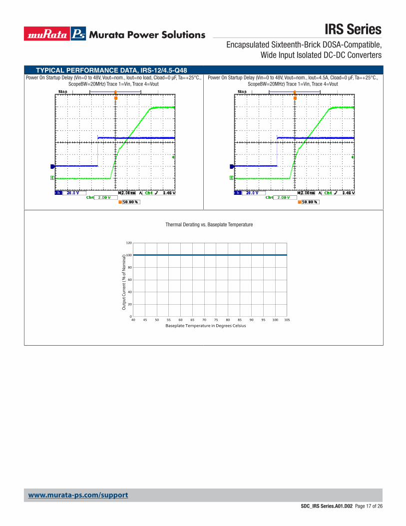
TYPICAL PERFORMANCE DATA, IRS-12/4.5-Q48Power On Startup Delay (Vin=0 to 48V, Vout=nom., Iout=no load, Cload=0 µF, Ta=+25°C.,
ScopeBW=20MHz) Trace 1=Vin, Trace 4=VoutPower On Startup Delay (Vin=0 to 48V, Vout=nom., Iout=4.5A, Cload=0 µF, Ta=+25°C.,
ScopeBW=20MHz) Trace 1=Vin, Trace 4=Vout
Thermal Derating vs. Baseplate Temperature
0
20
40
60
80
100
120
40 45 50 55 60 65 70 75 80 85 90 95 100 105
Out
put C
urre
nt (
% o
f Nom
inal
)
Baseplate Temperature in Degrees Celsius
www.murata-ps.com/support
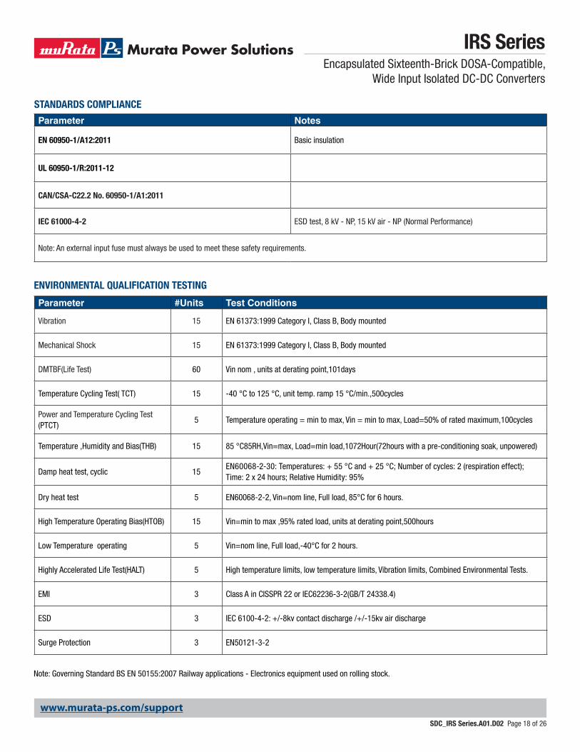
STANDARDS COMPLIANCE
Parameter Notes
EN 60950-1/A12:2011 Basic insulation
UL 60950-1/R:2011-12
CAN/CSA-C22.2 No. 60950-1/A1:2011
IEC 61000-4-2 ESD test, 8 kV - NP, 15 kV air - NP (Normal Performance)
Note: An external input fuse must always be used to meet these safety requirements.
Parameter #Units Test Conditions
Vibration 15 EN 61373:1999 Category I, Class B, Body mounted
Mechanical Shock 15 EN 61373:1999 Category I, Class B, Body mounted
DMTBF(Life Test) 60 Vin nom , units at derating point,101days
Temperature Cycling Test( TCT) 15 -40 °C to 125 °C, unit temp. ramp 15 °C/min.,500cycles
Power and Temperature Cycling Test (PTCT)
5 Temperature operating = min to max, Vin = min to max, Load=50% of rated maximum,100cycles
Temperature ,Humidity and Bias(THB) 15 85 °C85RH,Vin=max, Load=min load,1072Hour(72hours with a pre-conditioning soak, unpowered)
Damp heat test, cyclic 15EN60068-2-30: Temperatures: + 55 °C and + 25 °C; Number of cycles: 2 (respiration effect); Time: 2 x 24 hours; Relative Humidity: 95%
Dry heat test 5 EN60068-2-2, Vin=nom line, Full load, 85°C for 6 hours.
High Temperature Operating Bias(HTOB) 15 Vin=min to max ,95% rated load, units at derating point,500hours
Low Temperature operating 5 Vin=nom line, Full load,-40°C for 2 hours.
Highly Accelerated Life Test(HALT) 5 High temperature limits, low temperature limits, Vibration limits, Combined Environmental Tests.
EMI 3 Class A in CISSPR 22 or IEC62236-3-2(GB/T 24338.4)
ESD 3 IEC 6100-4-2: +/-8kv contact discharge /+/-15kv air discharge
Surge Protection 3 EN50121-3-2
ENVIRONMENTAL QUALIFICATION TESTING
Note: Governing Standard BS EN 50155:2007 Railway applications - Electronics equipment used on rolling stock.
IRS SeriesEncapsulated Sixteenth-Brick DOSA-Compatible,
Wide Input Isolated DC-DC Converters
SDC_IRS Series.A01.D02 Page 18 of 26
www.murata-ps.com/support
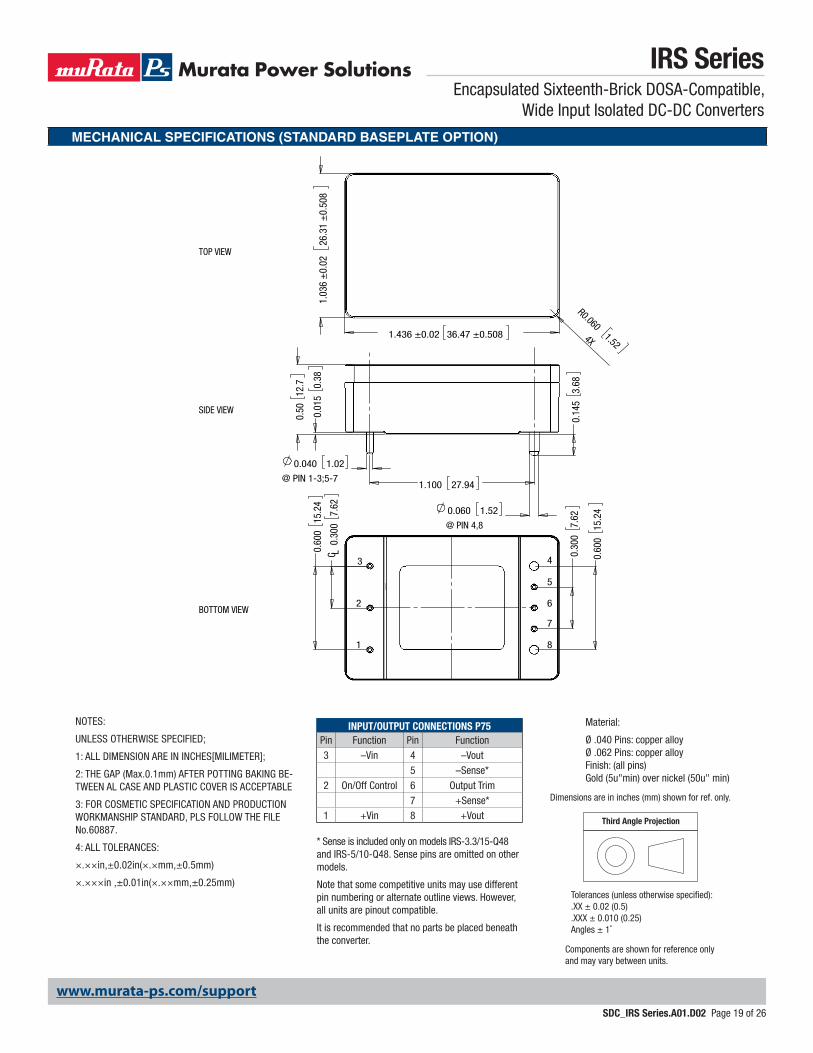
MECHANICAL SPECIFICATIONS (STANDARD BASEPLATE OPTION)
IRS SeriesEncapsulated Sixteenth-Brick DOSA-Compatible,
Wide Input Isolated DC-DC Converters
SDC_IRS Series.A01.D02 Page 19 of 26
INPUT/OUTPUT CONNECTIONS P75Pin Function Pin Function3 –Vin 4 –Vout
5 –Sense*2 On/Off Control 6 Output Trim
7 +Sense*1 +Vin 8 +Vout
* Sense is included only on models IRS-3.3/15-Q48 and IRS-5/10-Q48. Sense pins are omitted on other models.
Note that some competitive units may use different pin numbering or alternate outline views. However, all units are pinout compatible.
It is recommended that no parts be placed beneath the converter.
NOTES:
UNLESS OTHERWISE SPECIFIED;
1: ALL DIMENSION ARE IN INCHES[MILIMETER];
2: THE GAP (Max.0.1mm) AFTER POTTING BAKING BE-TWEEN AL CASE AND PLASTIC COVER IS ACCEPTABLE
3: FOR COSMETIC SPECIFICATION AND PRODUCTION WORKMANSHIP STANDARD, PLS FOLLOW THE FILE No.60887.
4: ALL TOLERANCES:
×.××in,±0.02in(×.×mm,±0.5mm)
×.×××in ,±0.01in(×.××mm,±0.25mm)
Third Angle Projection
Dimensions are in inches (mm) shown for ref. only.
Components are shown for reference onlyand may vary between units.
Tolerances (unless otherwise specified):.XX ± 0.02 (0.5).XXX ± 0.010 (0.25)Angles ± 1˚
Material:
Ø .040 Pins: copper alloy Ø .062 Pins: copper alloy Finish: (all pins) Gold (5u"min) over nickel (50u" min)
0.60
015
.24
0.30
07.
62
0.60
015
.24
C L0.
300
7.62
0.50
12.7
0.060 1.52
@ PIN 4,8
0.040 1.02
@ PIN 1-3;5-7
0.01
50.
38
1.100 27.94
0.14
53.
68
1.436 ±0.02 36.47 ±0.5081.
036
±0.
0226
.31
±0.
508
R0.0601.52
4X
1
3
2
4
5
6
7
8
BOTTOM VIEW
SIDE VIEW
TOP VIEW
www.murata-ps.com/support
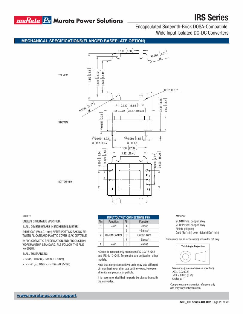
MECHANICAL SPECIFICATIONS(FLANGED BASEPLATE OPTION)
IRS SeriesEncapsulated Sixteenth-Brick DOSA-Compatible,
Wide Input Isolated DC-DC Converters
SDC_IRS Series.A01.D02 Page 20 of 26
0.60
015
.24
0.30
07.
62
0.60
015
.241.12 28.4
C L0.
300
7.62
0.060 1.52
@ PIN 4,8
0.040 1.02
@ PIN 1-3;5-7
0.01
50.
38
0.50
12.7
1.100 27.94
0.14
53.
68
1.04
026
.42
1.44 ±0.02 36.47 ±0.508
0.730 18.54
1.30
033
.02
1.50
38.1
0.130 3.30
R0.062 1.57
4X
R0.0701.78
3X
0.10"X0.10"
1
3
2
4
5
6
7
8
BOTTOM VIEW
SIDE VIEW
TOP VIEW
INPUT/OUTPUT CONNECTIONS P75Pin Function Pin Function3 –Vin 4 –Vout
5 –Sense*2 On/Off Control 6 Output Trim
7 +Sense*1 +Vin 8 +Vout
* Sense is included only on models IRS-3.3/15-Q48 and IRS-5/10-Q48. Sense pins are omitted on other models.
Note that some competitive units may use different pin numbering or alternate outline views. However, all units are pinout compatible.
It is recommended that no parts be placed beneath the converter.
Third Angle Projection
Dimensions are in inches (mm) shown for ref. only.
Components are shown for reference onlyand may vary between units.
Tolerances (unless otherwise specified):.XX ± 0.02 (0.5).XXX ± 0.010 (0.25)Angles ± 1˚
Material:
Ø .040 Pins: copper alloy Ø .062 Pins: copper alloy Finish: (all pins) Gold (5u"min) over nickel (50u" min)
NOTES:
UNLESS OTHERWISE SPECIFIED;
1: ALL DIMENSION ARE IN INCHES[MILIMETER];
2:THE GAP (Max.0.1mm) AFTER POTTING BAKING BE-TWEEN AL CASE AND PLASTIC COVER IS AC CEPTABLE
3: FOR COSMETIC SPECIFICATION AND PRODUCTION WORKMANSHIP STANDARD, PLS FOLLOW THE FILE No.60887.
4: ALL TOLERANCES:
×.××in,±0.02in(×.×mm,±0.5mm)
×.×××in ,±0.01in(×.××mm,±0.25mm)

www.murata-ps.com/support
MECHANICAL SPECIFICATIONS
INPUT/OUTPUT CONNECTIONS P75Pin Function Pin Function3 –Vin 4 –Vout
5 –Sense*2 On/Off Control 6 Output Trim
7 +Sense*1 +Vin 8 +Vout
.9223.4
.100 MinAnnular Ring
For All PinShoulders
.3007.62
.3007.62
1.100
33.51.32
11.7.46
14.0.55
3.81.150
3.81.150
Recommended Footprint (View Through Converter)
1
2
34
8
CL Finished Hole Sizes@ Pins 4 & 8
(Per Ipc-d-275, Level C).070-.084
(Sec)
CL
(Pri)
CL
Top ViewFinished Hole Sizes@ Pins 1-3, 6, 5*, 7*
(Per Ipc-d-275, Level C) .048-.062
5*
7*
6
*Sense is included only on models IRS-3.3/15-Q48. Sense pins are omitted on other models.
IRS SeriesEncapsulated Sixteenth-Brick DOSA-Compatible,
Wide Input Isolated DC-DC Converters
SDC_IRS Series.A01.D02 Page 21 of 26
www.murata-ps.com/support
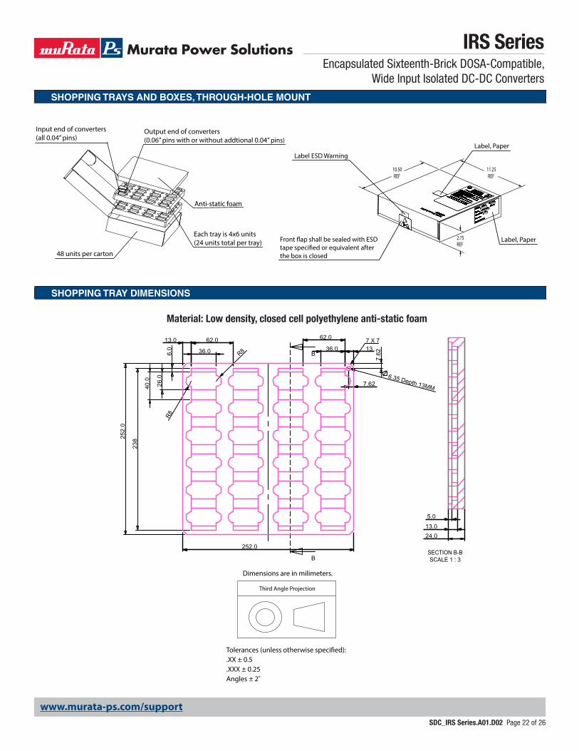
SHOPPING TRAYS AND BOXES, THROUGH-HOLE MOUNT
SHOPPING TRAY DIMENSIONS
36.0
26.
0 6
.0
R8
40.
0
252
.0
62.0 13.0
238
13 36.0
62.0
R8
252.0
6.35 Depth 13MM 7.62
7.6
2 B
B
7 X 7
5.0 13.0 24.0
SECTION B-BSCALE 1 : 3
Material: Low density, closed cell polyethylene anti-static foam
Third Angle Projection
Dimensions are in milimeters.
Tolerances (unless otherwise specified):.XX ± 0.5.XXX ± 0.25Angles ± 2˚
IRS SeriesEncapsulated Sixteenth-Brick DOSA-Compatible,
Wide Input Isolated DC-DC Converters
SDC_IRS Series.A01.D02 Page 22 of 26
2.75REF
10.50REF
11.25REF
Front ap shall be sealed with ESD tape specied or equivalent after the box is closed
Label, PaperLabel ESD Warning
Label, Paper
Input end of converters(all 0.04’’ pins)
Output end of converters(0.06’’ pins with or without addtional 0.04’’ pins)
48 units per carton
Each tray is 4x6 units(24 units total per tray)
Anti-static foam
www.murata-ps.com/support
IRS SeriesEncapsulated Sixteenth-Brick DOSA-Compatible,
Wide Input Isolated DC-DC Converters
SDC_IRS Series.A01.D02 Page 23 of 26
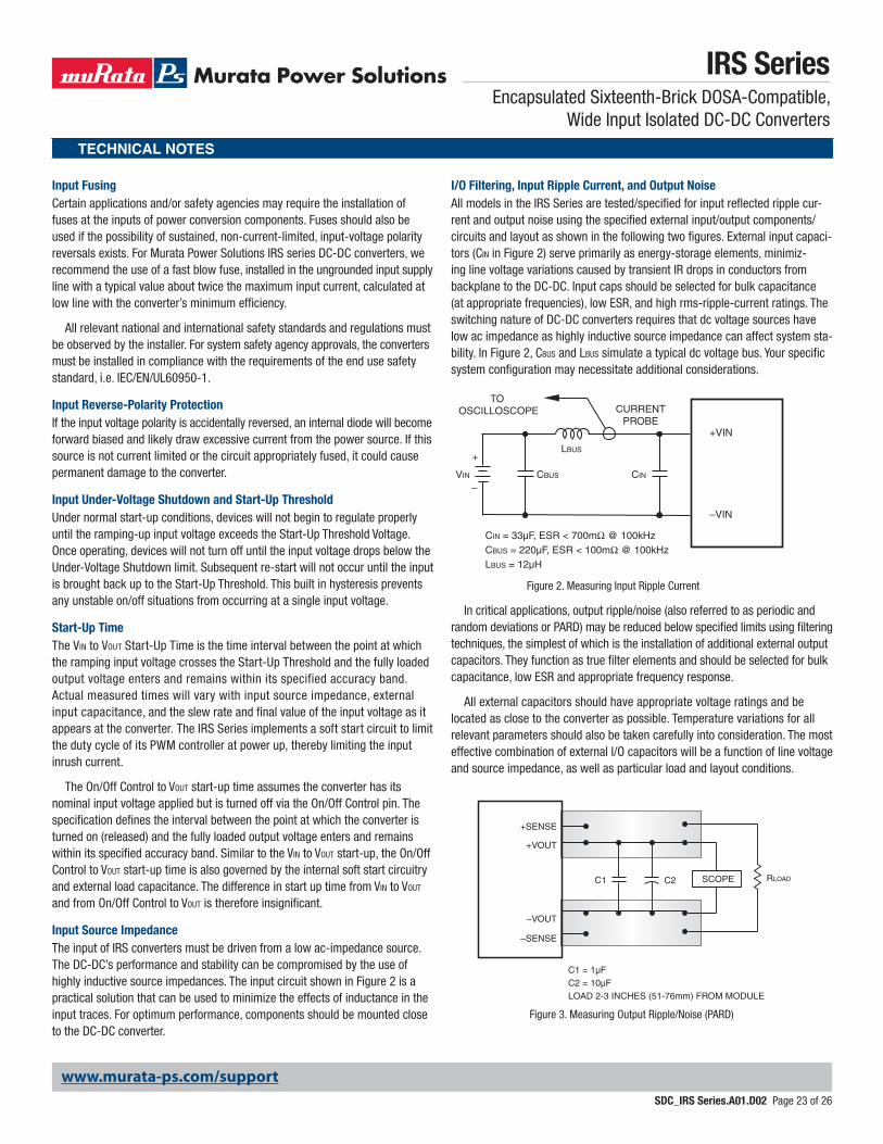
I/O Filtering, Input Ripple Current, and Output Noise All models in the IRS Series are tested/specified for input reflected ripple cur-rent and output noise using the specified external input/output components/circuits and layout as shown in the following two figures. External input capaci-tors (CIN in Figure 2) serve primarily as energy-storage elements, minimiz-ing line voltage variations caused by transient IR drops in conductors from backplane to the DC-DC. Input caps should be selected for bulk capacitance (at appropriate frequencies), low ESR, and high rms-ripple-current ratings. The switching nature of DC-DC converters requires that dc voltage sources have low ac impedance as highly inductive source impedance can affect system sta-bility. In Figure 2, CBUS and LBUS simulate a typical dc voltage bus. Your specific system configuration may necessitate additional considerations.
In critical applications, output ripple/noise (also referred to as periodic and random deviations or PARD) may be reduced below specified limits using filtering techniques, the simplest of which is the installation of additional external output capacitors. They function as true filter elements and should be selected for bulk capacitance, low ESR and appropriate frequency response.
All external capacitors should have appropriate voltage ratings and be located as close to the converter as possible. Temperature variations for all relevant parameters should also be taken carefully into consideration. The most effective combination of external I/O capacitors will be a function of line voltage and source impedance, as well as particular load and layout conditions.
Input Fusing Certain applications and/or safety agencies may require the installation of fuses at the inputs of power conversion components. Fuses should also be used if the possibility of sustained, non-current-limited, input-voltage polarity reversals exists. For Murata Power Solutions IRS series DC-DC converters, we recommend the use of a fast blow fuse, installed in the ungrounded input supply line with a typical value about twice the maximum input current, calculated at low line with the converter’s minimum efficiency.
All relevant national and international safety standards and regulations must be observed by the installer. For system safety agency approvals, the converters must be installed in compliance with the requirements of the end use safety standard, i.e. IEC/EN/UL60950-1.
Input Reverse-Polarity ProtectionIf the input voltage polarity is accidentally reversed, an internal diode will become forward biased and likely draw excessive current from the power source. If this source is not current limited or the circuit appropriately fused, it could cause permanent damage to the converter.
Input Under-Voltage Shutdown and Start-Up ThresholdUnder normal start-up conditions, devices will not begin to regulate properly until the ramping-up input voltage exceeds the Start-Up Threshold Voltage. Once operating, devices will not turn off until the input voltage drops below the Under-Voltage Shutdown limit. Subsequent re-start will not occur until the input is brought back up to the Start-Up Threshold. This built in hysteresis prevents any unstable on/off situations from occurring at a single input voltage.
Start-Up Time The VIN to VOUT Start-Up Time is the time interval between the point at which the ramping input voltage crosses the Start-Up Threshold and the fully loaded output voltage enters and remains within its specified accuracy band. Actual measured times will vary with input source impedance, external input capacitance, and the slew rate and final value of the input voltage as it appears at the converter. The IRS Series implements a soft start circuit to limit the duty cycle of its PWM controller at power up, thereby limiting the input inrush current.
The On/Off Control to VOUT start-up time assumes the converter has its nominal input voltage applied but is turned off via the On/Off Control pin. The specification defines the interval between the point at which the converter is turned on (released) and the fully loaded output voltage enters and remains within its specified accuracy band. Similar to the VIN to VOUT start-up, the On/Off Control to VOUT start-up time is also governed by the internal soft start circuitry and external load capacitance. The difference in start up time from VIN to VOUT and from On/Off Control to VOUT is therefore insignificant.
Input Source ImpedanceThe input of IRS converters must be driven from a low ac-impedance source. The DC-DC’s performance and stability can be compromised by the use of highly inductive source impedances. The input circuit shown in Figure 2 is a practical solution that can be used to minimize the effects of inductance in the input traces. For optimum performance, components should be mounted close to the DC-DC converter.
CINVIN CBUS
LBUS
CIN = 33µF, ESR < 700mΩ @ 100kHzCBUS = 220µF, ESR < 100mΩ @ 100kHzLBUS = 12µH
+VIN
–VIN
CURRENTPROBE
TO OSCILLOSCOPE
+
–
Figure 2. Measuring Input Ripple Current
TECHNICAL NOTES
C1
C1 = 1µF C2 = 10µF LOAD 2-3 INCHES (51-76mm) FROM MODULE
C2 RLOADSCOPE
+VOUT
–VOUT
+SENSE
–SENSE
Figure 3. Measuring Output Ripple/Noise (PARD)
www.murata-ps.com/support
IRS SeriesEncapsulated Sixteenth-Brick DOSA-Compatible,
Wide Input Isolated DC-DC Converters
SDC_IRS Series.A01.D02 Page 24 of 26
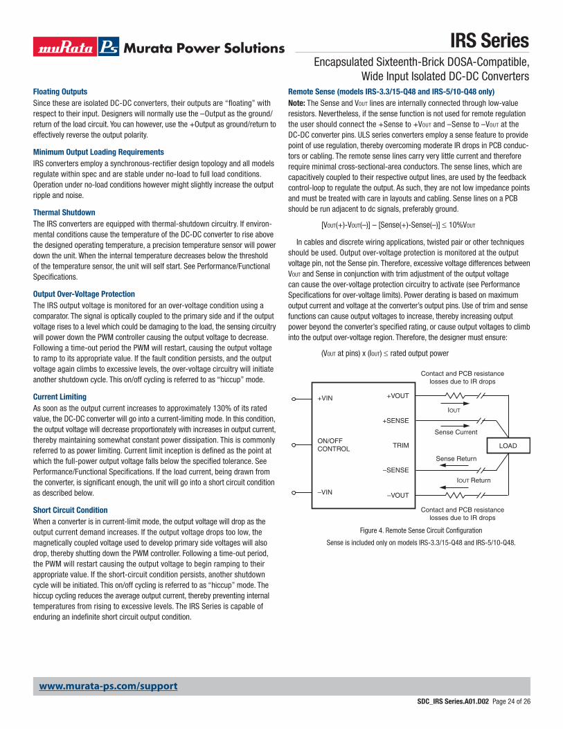
Remote Sense (models IRS-3.3/15-Q48 and IRS-5/10-Q48 only)Note: The Sense and VOUT lines are internally connected through low-value resistors. Nevertheless, if the sense function is not used for remote regulation the user should connect the +Sense to +VOUT and –Sense to –VOUT at the DC-DC converter pins. ULS series converters employ a sense feature to provide point of use regulation, thereby overcoming moderate IR drops in PCB conduc-tors or cabling. The remote sense lines carry very little current and therefore require minimal cross-sectional-area conductors. The sense lines, which are capacitively coupled to their respective output lines, are used by the feedback control-loop to regulate the output. As such, they are not low impedance points and must be treated with care in layouts and cabling. Sense lines on a PCB should be run adjacent to dc signals, preferably ground.
[VOUT(+)-VOUT(–)] – [Sense(+)-Sense(–)] ≤ 10%VOUT
In cables and discrete wiring applications, twisted pair or other techniques should be used. Output over-voltage protection is monitored at the output voltage pin, not the Sense pin. Therefore, excessive voltage differences between VOUT and Sense in conjunction with trim adjustment of the output voltage can cause the over-voltage protection circuitry to activate (see Performance Specifications for over-voltage limits). Power derating is based on maximum output current and voltage at the converter’s output pins. Use of trim and sense functions can cause output voltages to increase, thereby increasing output power beyond the converter’s specified rating, or cause output voltages to climb into the output over-voltage region. Therefore, the designer must ensure:
(VOUT at pins) x (IOUT) ≤ rated output power
LOAD
+VOUT+VIN
Sense Current
Contact and PCB resistancelosses due to IR drops
Contact and PCB resistancelosses due to IR drops
Sense Return
–VIN
ON/OFFCONTROL TRIM
+SENSE
–VOUT
–SENSE
IOUT Return
IOUT
Figure 4. Remote Sense Circuit Configuration
Sense is included only on models IRS-3.3/15-Q48 and IRS-5/10-Q48.
Floating Outputs Since these are isolated DC-DC converters, their outputs are “floating” with respect to their input. Designers will normally use the –Output as the ground/return of the load circuit. You can however, use the +Output as ground/return to effectively reverse the output polarity.
Minimum Output Loading Requirements IRS converters employ a synchronous-rectifier design topology and all models regulate within spec and are stable under no-load to full load conditions. Operation under no-load conditions however might slightly increase the output ripple and noise.
Thermal Shutdown The IRS converters are equipped with thermal-shutdown circuitry. If environ-mental conditions cause the temperature of the DC-DC converter to rise above the designed operating temperature, a precision temperature sensor will power down the unit. When the internal temperature decreases below the threshold of the temperature sensor, the unit will self start. See Performance/Functional Specifications.
Output Over-Voltage Protection The IRS output voltage is monitored for an over-voltage condition using a comparator. The signal is optically coupled to the primary side and if the output voltage rises to a level which could be damaging to the load, the sensing circuitry will power down the PWM controller causing the output voltage to decrease. Following a time-out period the PWM will restart, causing the output voltage to ramp to its appropriate value. If the fault condition persists, and the output voltage again climbs to excessive levels, the over-voltage circuitry will initiate another shutdown cycle. This on/off cycling is referred to as “hiccup” mode.
Current Limiting As soon as the output current increases to approximately 130% of its rated value, the DC-DC converter will go into a current-limiting mode. In this condition, the output voltage will decrease proportionately with increases in output current, thereby maintaining somewhat constant power dissipation. This is commonly referred to as power limiting. Current limit inception is defined as the point at which the full-power output voltage falls below the specified tolerance. See Performance/Functional Specifications. If the load current, being drawn from the converter, is significant enough, the unit will go into a short circuit condition as described below.
Short Circuit ConditionWhen a converter is in current-limit mode, the output voltage will drop as the output current demand increases. If the output voltage drops too low, the magnetically coupled voltage used to develop primary side voltages will also drop, thereby shutting down the PWM controller. Following a time-out period, the PWM will restart causing the output voltage to begin ramping to their appropriate value. If the short-circuit condition persists, another shutdown cycle will be initiated. This on/off cycling is referred to as “hiccup” mode. The hiccup cycling reduces the average output current, thereby preventing internal temperatures from rising to excessive levels. The IRS Series is capable of enduring an indefinite short circuit output condition.
www.murata-ps.com/support
IRS SeriesEncapsulated Sixteenth-Brick DOSA-Compatible,
Wide Input Isolated DC-DC Converters
SDC_IRS Series.A01.D02 Page 25 of 26
OUTPUT VOLTAGE ADJUSTMENT
DOWNRT (kΩ) =
Where ∆% = |( × 100 )|– 10.22
∆%
511
Trim Down
Trim Equations
Trim Up
UPRT (kΩ) = –1.225 × ∆%
5.11 × VNOM × (100 + ∆%)
∆%
511– 10.22
VNOM – VDES
VNOM
Note: “∆%” is always a positive value. “VNOM” is the nominal, rated output voltage. “VDES” is the desired, changed output voltage.
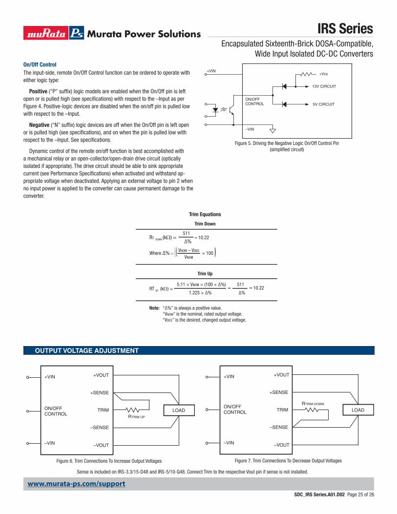
Figure 6. Trim Connections To Increase Output Voltages
LOADRTRIM UP
+VOUT+VIN
–VIN
ON/OFFCONTROL
TRIM
+SENSE
–VOUT
–SENSE
LOADRTRIM DOWN
+VOUT+VIN
–VIN
ON/OFFCONTROL TRIM
+SENSE
–VOUT
–SENSE
Figure 7. Trim Connections To Decrease Output Voltages
Sense is included on IRS-3.3/15-D48 and IRS-5/10-Q48. Connect Trim to the respective Vout pin if sense is not installed.
+Vcc
13V CIRCUIT
5V CIRCUIT
–VIN
O N /O F F C O N TR O L
+VIN
Figure 5. Driving the Negative Logic On/Off Control Pin (simplified circuit)
On/Off ControlThe input-side, remote On/Off Control function can be ordered to operate with either logic type:
Positive ("P" suffix) logic models are enabled when the On/Off pin is left open or is pulled high (see specifications) with respect to the –Input as per Figure 4. Positive-logic devices are disabled when the on/off pin is pulled low with respect to the –Input.
Negative (“N” suffix) logic devices are off when the On/Off pin is left open or is pulled high (see specifications), and on when the pin is pulled low with respect to the –Input. See specifications.
Dynamic control of the remote on/off function is best accomplished with a mechanical relay or an open-collector/open-drain drive circuit (optically isolated if appropriate). The drive circuit should be able to sink appropriate current (see Performance Specifications) when activated and withstand ap-propriate voltage when deactivated. Applying an external voltage to pin 2 when no input power is applied to the converter can cause permanent damage to the converter.
www.murata-ps.com/support
Murata Power Solutions, Inc. makes no representation that the use of its products in the circuits described herein, or the use of other technical information contained herein, will not infringe upon existing or future patent rights. The descriptions contained herein do not imply the granting of licenses to make, use, or sell equipment constructed in accordance therewith. Specifications are subject to change without notice. © 2017 Murata Power Solutions, Inc.
Murata Power Solutions, Inc. 129 Flanders Rd, Westborough, MA 01581 USAISO 9001 and 14001 REGISTERED
This product is subject to the following operating requirements and the Life and Safety Critical Application Sales Policy: Refer to: http://www.murata-ps.com/requirements/
IRS SeriesEncapsulated Sixteenth-Brick DOSA-Compatible,
Wide Input Isolated DC-DC Converters
SDC_IRS Series.A01.D02 Page 26 of 26
Through-hole Soldering Guidelines
Murata Power Solutions recommends the TH soldering specifications below when install-ing these converters. These specifications vary depending on the solder type. Exceeding these specifications may cause damage to the product. Your production environment may
differ; therefore please thoroughly review these guidelines with your process engineers.
Wave Solder Operations for through-hole mounted products (THMT)
For Sn/Ag/Cu based solders:
Maximum Preheat Temperature 115° C.
Maximum Pot Temperature 270° C.
Maximum Solder Dwell Time 7 seconds
For Sn/Pb based solders:
Maximum Preheat Temperature 105° C.
Maximum Pot Temperature 250° C.
Maximum Solder Dwell Time 6 seconds
SMT Reflow Soldering Guidelines
The surface-mount reflow solder profile shown below is suitable for SAC305 type lead-free solders. This graph should be used only as a guideline. Many other factors influence the success of SMT reflow soldering. Since your production environment may differ, please thoroughly review these guidelines with your process engineers.
Tem
pera
ture
(°C)
Time (minutes)
Optimal peak 245°C; max peak 260°C
SAC305 liquidus @ 219°C
Ramp @ 1°C/second across liquidus
Adjust ram
p for s
oak if
require
d
Keep ra
mp rates
under 2°C/se
cond
TAL @ 60 seconds (range 45–75 seconds)
Cooling rate 2–3°C/second
260
240
220
200
180
160
140
120
100
80
60
40
200 1 2 3 4 5 6 7
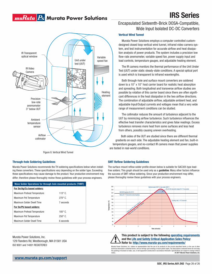
Figure 8. Vertical Wind Tunnel
IR Video Camera
IR Transparentoptical window Variable
speed fan
Heating element
Ambient temperature
sensor
Airflowcollimator
Precisionlow-rate
anemometer3” below UUT
Unit undertest (UUT)
Vertical Wind Tunnel
Murata Power Solutions employs a computer controlled custom-designed closed loop vertical wind tunnel, infrared video camera sys-tem, and test instrumentation for accurate airflow and heat dissipa-tion analysis of power products. The system includes a precision low flow-rate anemometer, variable speed fan, power supply input and load controls, temperature gauges, and adjustable heating element.
The IR camera monitors the thermal performance of the Unit Under Test (UUT) under static steady-state conditions. A special optical port is used which is transparent to infrared wavelengths.
Both through-hole and surface mount converters are soldered down to a 10" x 10" host carrier board for realistic heat absorption and spreading. Both longitudinal and transverse airflow studies are possible by rotation of this carrier board since there are often signifi-cant differences in the heat dissipation in the two airflow directions. The combination of adjustable airflow, adjustable ambient heat, and adjustable Input/Output currents and voltages mean that a very wide range of measurement conditions can be studied.
The collimator reduces the amount of turbulence adjacent to the UUT by minimizing airflow turbulence. Such turbulence influences the effective heat transfer characteristics and gives false readings. Excess turbulence removes more heat from some surfaces and less heat from others, possibly causing uneven overheating.
Both sides of the UUT are studied since there are different thermal gradients on each side. The adjustable heating element and fan, built-in
temperature gauges, and no-contact IR camera mean that power supplies are tested in real-world conditions.