Embed Size (px)
Citation preview
GEOTECHNICAL REPORT, SPECIFICATIONS, AND BID ITEMS
FOR
Paving, Grading, and Drainage Improvements
to serve
County Road 1230 Extension &
County Road 140 Improvements
COUNTY PROJECT NO. 16MCO516
COUNTY JUDGE
Michael R. Bradford
COUNTY COMMISSIONERS
Jimmy Smith – Precinct 1
Robin Donnelly – Precinct 2
Luis D. Sanchez – Precinct 3
Randy Prude – Precinct 4
PREPARED BY
Dunaway No. B001484.001
July 2016
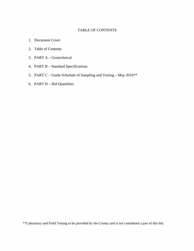
TABLE OF CONTENTS
1. Document Cover
2. Table of Contents
3. PART A – Geotechnical
4. PART B – Standard Specifications
5. PART C – Guide Schedule of Sampling and Testing – May 2016**
6. PART D – Bid Quantities
**Laboratory and Field Testing to be provided by the County and is not considered a part of this bid.

PART A
GEOTECHNICAL ASSESSMENT
www.RRCcompanies.com
3011 South County Road 1260 Midland, TX 79706
432.561.5780
www.RRCcompanies.com experience matters
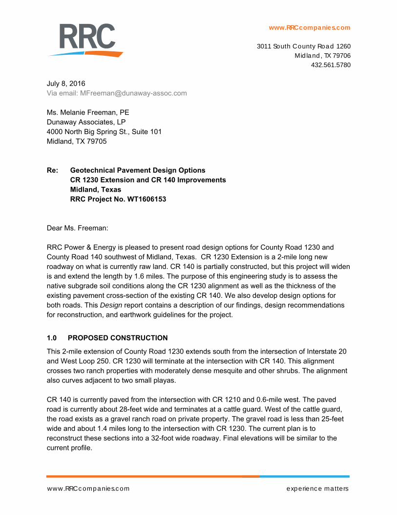
July 8, 2016
Via email: [email protected] Ms. Melanie Freeman, PE Dunaway Associates, LP 4000 North Big Spring St., Suite 101 Midland, TX 79705 Re: Geotechnical Pavement Design Options CR 1230 Extension and CR 140 Improvements
Midland, Texas RRC Project No. WT1606153 Dear Ms. Freeman: RRC Power & Energy is pleased to present road design options for County Road 1230 and County Road 140 southwest of Midland, Texas. CR 1230 Extension is a 2-mile long new roadway on what is currently raw land. CR 140 is partially constructed, but this project will widen is and extend the length by 1.6 miles. The purpose of this engineering study is to assess the native subgrade soil conditions along the CR 1230 alignment as well as the thickness of the existing pavement cross-section of the existing CR 140. We also develop design options for both roads. This Design report contains a description of our findings, design recommendations for reconstruction, and earthwork guidelines for the project.
1.0 PROPOSED CONSTRUCTION
This 2-mile extension of County Road 1230 extends south from the intersection of Interstate 20 and West Loop 250. CR 1230 will terminate at the intersection with CR 140. This alignment crosses two ranch properties with moderately dense mesquite and other shrubs. The alignment also curves adjacent to two small playas. CR 140 is currently paved from the intersection with CR 1210 and 0.6-mile west. The paved road is currently about 28-feet wide and terminates at a cattle guard. West of the cattle guard, the road exists as a gravel ranch road on private property. The gravel road is less than 25-feet wide and about 1.4 miles long to the intersection with CR 1230. The current plan is to reconstruct these sections into a 32-foot wide roadway. Final elevations will be similar to the current profile.
Geo Pavement Designs 7/8/2016 CR 1230 and CR 140 - Midland, Texas Page 2 of 6
www.RRCcompanies.com experience matters
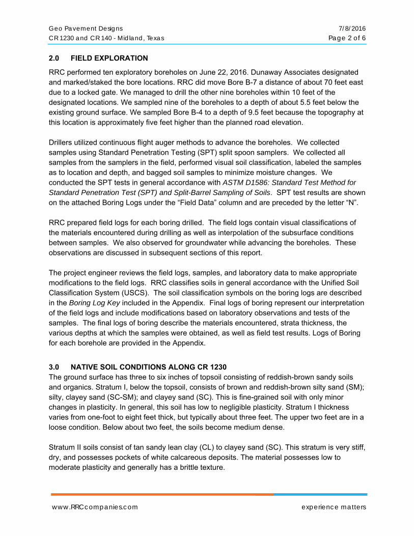
2.0 FIELD EXPLORATION
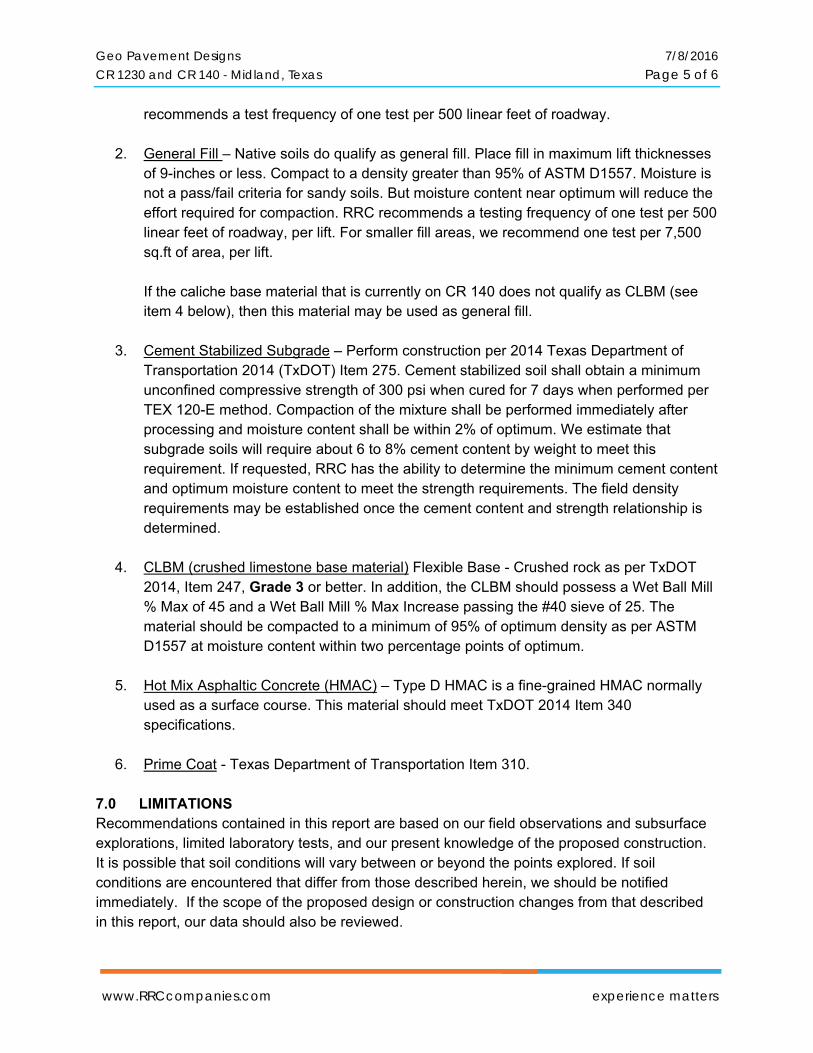
RRC performed ten exploratory boreholes on June 22, 2016. Dunaway Associates designated and marked/staked the bore locations. RRC did move Bore B-7 a distance of about 70 feet east due to a locked gate. We managed to drill the other nine boreholes within 10 feet of the designated locations. We sampled nine of the boreholes to a depth of about 5.5 feet below the existing ground surface. We sampled Bore B-4 to a depth of 9.5 feet because the topography at this location is approximately five feet higher than the planned road elevation. Drillers utilized continuous flight auger methods to advance the boreholes. We collected samples using Standard Penetration Testing (SPT) split spoon samplers. We collected all samples from the samplers in the field, performed visual soil classification, labeled the samples as to location and depth, and bagged soil samples to minimize moisture changes. We conducted the SPT tests in general accordance with ASTM D1586: Standard Test Method for Standard Penetration Test (SPT) and Split-Barrel Sampling of Soils. SPT test results are shown on the attached Boring Logs under the “Field Data” column and are preceded by the letter “N”. RRC prepared field logs for each boring drilled. The field logs contain visual classifications of the materials encountered during drilling as well as interpolation of the subsurface conditions between samples. We also observed for groundwater while advancing the boreholes. These observations are discussed in subsequent sections of this report. The project engineer reviews the field logs, samples, and laboratory data to make appropriate modifications to the field logs. RRC classifies soils in general accordance with the Unified Soil Classification System (USCS). The soil classification symbols on the boring logs are described in the Boring Log Key included in the Appendix. Final logs of boring represent our interpretation of the field logs and include modifications based on laboratory observations and tests of the samples. The final logs of boring describe the materials encountered, strata thickness, the various depths at which the samples were obtained, as well as field test results. Logs of Boring for each borehole are provided in the Appendix.
3.0 NATIVE SOIL CONDITIONS ALONG CR 1230 The ground surface has three to six inches of topsoil consisting of reddish-brown sandy soils and organics. Stratum I, below the topsoil, consists of brown and reddish-brown silty sand (SM); silty, clayey sand (SC-SM); and clayey sand (SC). This is fine-grained soil with only minor changes in plasticity. In general, this soil has low to negligible plasticity. Stratum I thickness varies from one-foot to eight feet thick, but typically about three feet. The upper two feet are in a loose condition. Below about two feet, the soils become medium dense. Stratum II soils consist of tan sandy lean clay (CL) to clayey sand (SC). This stratum is very stiff, dry, and possesses pockets of white calcareous deposits. The material possesses low to moderate plasticity and generally has a brittle texture.
Geo Pavement Designs 7/8/2016 CR 1230 and CR 140 - Midland, Texas Page 3 of 6
www.RRCcompanies.com experience matters
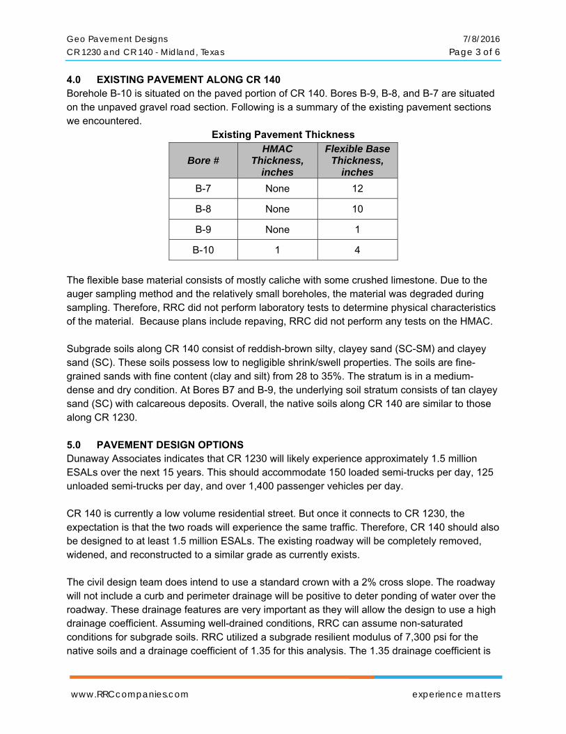
4.0 EXISTING PAVEMENT ALONG CR 140 Borehole B-10 is situated on the paved portion of CR 140. Bores B-9, B-8, and B-7 are situated on the unpaved gravel road section. Following is a summary of the existing pavement sections we encountered.
Existing Pavement Thickness
Bore # HMAC
Thickness, inches
Flexible Base Thickness,
inches
B-7 None 12
B-8 None 10
B-9 None 1
B-10 1 4
The flexible base material consists of mostly caliche with some crushed limestone. Due to the auger sampling method and the relatively small boreholes, the material was degraded during sampling. Therefore, RRC did not perform laboratory tests to determine physical characteristics of the material. Because plans include repaving, RRC did not perform any tests on the HMAC. Subgrade soils along CR 140 consist of reddish-brown silty, clayey sand (SC-SM) and clayey sand (SC). These soils possess low to negligible shrink/swell properties. The soils are fine-grained sands with fine content (clay and silt) from 28 to 35%. The stratum is in a medium-dense and dry condition. At Bores B7 and B-9, the underlying soil stratum consists of tan clayey sand (SC) with calcareous deposits. Overall, the native soils along CR 140 are similar to those along CR 1230. 5.0 PAVEMENT DESIGN OPTIONS Dunaway Associates indicates that CR 1230 will likely experience approximately 1.5 million ESALs over the next 15 years. This should accommodate 150 loaded semi-trucks per day, 125 unloaded semi-trucks per day, and over 1,400 passenger vehicles per day. CR 140 is currently a low volume residential street. But once it connects to CR 1230, the expectation is that the two roads will experience the same traffic. Therefore, CR 140 should also be designed to at least 1.5 million ESALs. The existing roadway will be completely removed, widened, and reconstructed to a similar grade as currently exists. The civil design team does intend to use a standard crown with a 2% cross slope. The roadway will not include a curb and perimeter drainage will be positive to deter ponding of water over the roadway. These drainage features are very important as they will allow the design to use a high drainage coefficient. Assuming well-drained conditions, RRC can assume non-saturated conditions for subgrade soils. RRC utilized a subgrade resilient modulus of 7,300 psi for the native soils and a drainage coefficient of 1.35 for this analysis. The 1.35 drainage coefficient is
Geo Pavement Designs 7/8/2016 CR 1230 and CR 140 - Midland, Texas Page 4 of 6
www.RRCcompanies.com experience matters
justified if the area drainage allows dry conditions for 99% of the time. If any sections of the roadway might encounter saturated conditions due to poor drainage, RRC recommends cement stabilizing the subgrade soils in those limited sections. By cement stabilizing native subgrade soils to a depth of six inches, RRC estimates an effective layer coefficient of 0.15 for the stabilized layer.
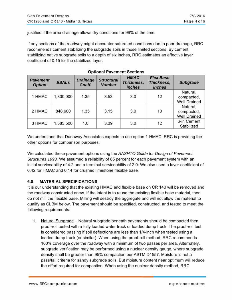
Optional Pavement Sections
Pavement Option
ESALs Drainage
Coeff. Structural Number
HMAC Thickness,
inches
Flex Base Thickness,
inches Subgrade
1 HMAC 1,800,000 1.35 3.53 3.0 12 Natural,
compacted, Well Drained
2 HMAC 848,600 1.35 3.15 3.0 10 Natural,
compacted, Well Drained
3 HMAC 1,385,500 1.0 3.39 3.0 12 6-in Cement Stabilized
We understand that Dunaway Associates expects to use option 1-HMAC. RRC is providing the other options for comparison purposes. We calculated these pavement options using the AASHTO Guide for Design of Pavement Structures 1993. We assumed a reliability of 85 percent for each pavement system with an initial serviceability of 4.2 and a terminal serviceability of 2.0. We also used a layer coefficient of 0.42 for HMAC and 0.14 for crushed limestone flexible base. 6.0 MATERIAL SPECIFICATIONS It is our understanding that the existing HMAC and flexible base on CR 140 will be removed and the roadway constructed anew. If the intent is to reuse the existing flexible base material, then do not mill the flexible base. Milling will destroy the aggregate and will not allow the material to qualify as CLBM below. The pavement should be specified, constructed, and tested to meet the following requirements:
1. Natural Subgrade – Natural subgrade beneath pavements should be compacted then proof-roll tested with a fully loaded water truck or loaded dump truck. The proof-roll test is considered passing if soil deflections are less than 1/4-inch when tested using a loaded dump truck (or similar). When using the proof-roll method, RRC recommends 100% coverage over the roadway with a minimum of two passes per area. Alternately, subgrade verification may be performed using a nuclear density gauge, where subgrade density shall be greater than 95% compaction per ASTM D1557. Moisture is not a pass/fail criteria for sandy subgrade soils. But moisture content near optimum will reduce the effort required for compaction. When using the nuclear density method, RRC
Geo Pavement Designs 7/8/2016 CR 1230 and CR 140 - Midland, Texas Page 5 of 6
www.RRCcompanies.com experience matters
recommends a test frequency of one test per 500 linear feet of roadway.
2. General Fill – Native soils do qualify as general fill. Place fill in maximum lift thicknesses of 9-inches or less. Compact to a density greater than 95% of ASTM D1557. Moisture is not a pass/fail criteria for sandy soils. But moisture content near optimum will reduce the effort required for compaction. RRC recommends a testing frequency of one test per 500 linear feet of roadway, per lift. For smaller fill areas, we recommend one test per 7,500 sq.ft of area, per lift. If the caliche base material that is currently on CR 140 does not qualify as CLBM (see item 4 below), then this material may be used as general fill.
3. Cement Stabilized Subgrade – Perform construction per 2014 Texas Department of
Transportation 2014 (TxDOT) Item 275. Cement stabilized soil shall obtain a minimum unconfined compressive strength of 300 psi when cured for 7 days when performed per TEX 120-E method. Compaction of the mixture shall be performed immediately after processing and moisture content shall be within 2% of optimum. We estimate that subgrade soils will require about 6 to 8% cement content by weight to meet this requirement. If requested, RRC has the ability to determine the minimum cement content and optimum moisture content to meet the strength requirements. The field density requirements may be established once the cement content and strength relationship is determined.
4. CLBM (crushed limestone base material) Flexible Base - Crushed rock as per TxDOT
2014, Item 247, Grade 3 or better. In addition, the CLBM should possess a Wet Ball Mill % Max of 45 and a Wet Ball Mill % Max Increase passing the #40 sieve of 25. The material should be compacted to a minimum of 95% of optimum density as per ASTM D1557 at moisture content within two percentage points of optimum.
5. Hot Mix Asphaltic Concrete (HMAC) – Type D HMAC is a fine-grained HMAC normally
used as a surface course. This material should meet TxDOT 2014 Item 340 specifications.
6. Prime Coat - Texas Department of Transportation Item 310.
7.0 LIMITATIONS Recommendations contained in this report are based on our field observations and subsurface explorations, limited laboratory tests, and our present knowledge of the proposed construction. It is possible that soil conditions will vary between or beyond the points explored. If soil conditions are encountered that differ from those described herein, we should be notified immediately. If the scope of the proposed design or construction changes from that described in this report, our data should also be reviewed.

Geo Pavement Designs 7/8/2016 CR 1230 and CR 140 - Midland, Texas Page 6 of 6
www.RRCcompanies.com experience matters
We prepared this report in substantial compliance with the generally accepted geotechnical engineering practice, as it exists in the area at the time of our study. No warranty is expressed or implied. The recommendations provided in this report are based on the assumption that RRC will conduct an adequate program of tests and observations during the construction phase in order to evaluate compliance with our recommendations.
This report may be used only by the client, Midland County, and the project design team and only for the purposes stated, within three years from its issuance. Land use, site conditions (both on site and off site) or other factors may change over time, and additional work may be required with the passage of time. Any party other than the client, or the client’s design team members for this particular project, who wishes to use this report shall notify RRC of such intended use. Based on the intended use of the report, RRC may require that additional work be performed and that an updated report be issued. Non-compliance with any of these requirements by the client or anyone else will release RRC from any liability resulting from the use of this report by any unauthorized party.
Respectfully submitted,
RRC Power & Energy, LLC
J. Edward Vasquez, P.E. Associate Principal
Enclosed: Bore Location Plan Logs of Boring B-1 through B-10. Moisture Density Curve of Subgrade
CR 1230 Extension & CR 140 Improvement – Midland County, TX
RRC Project 1606153 7/8/2016
Bore Location Plan
N
www.RRCcompanies.com3011 South County Road 1260
Midland, TX 79706432.561.5780
TO: PROJECT:
LOCATION:
PROJECT NO.:
DATE:
REPORT NO.:
MATERIAL DESCRIPTION:
SAMPLE LOCATION:
DATE SAMPLED:
SAMPLED BY:
SAMPLE NO.:
Test Method:
Preparation Method:
Rammer:
Compaction Method: A
Compactor:
Identification No.:
Calibrated Date:
Laboratory Manager:
3/4"
3/8"
No. 4
No. 10
No. 40
No. 100
No. 200
Maximum Dry Unit Weight (pcf):
Optimum Moisture Content (%):
LL
PL
PI
Copies To:
Copyright 2016 - RRC - All Rights Reserved
Specification
Atterberg Limits
Results
Geotech Bore No. 4
ASTM D1557-12
Moist
GPS: 31.925781, -102.133274
S-4308
6/23/2016
RRC - E. Zapata
The results shown on this report are for the exclusive use of the client for whom they were obtained and apply only to the sample tested and / or inspected. They are not intended to be indicative of qualities of apparently identical products. The use of our name must recieve prior written approval. Reports must be reproduced in their entirety. Unauthorized use or copying of this document is strictly
prohibited by anyone other than the client for the specific project.
SOIL CLASSIFICATION PER ASTM D2487
M100-210072016
Johnny Franks
RRC Power & Energy, LLC
ASTM C136 and D1140 Test Method:
Test Method: ASTM D4319
Quality Review
1-Above
Dunaway Associates, LP4000 North Big Spring ST, Suite 101Midland, TX 79705
CR 1230 Ext and CR 140 ImprovementsMidland, TX
January 13, 2016
WT1606153
606153.0623.2931
Attn: Melanie Freeman, PE
Ploog Engineering Co.
Red/Brown Silty Sand to Silty, Clayey Sand
Composite Sample: 0 ft - 8 ft,
June 29, 2016
MOISTURE - DENSITY RELATIONSHIP
CURVE RESULTS
Sieve Analysis
% Retained SpecificationSieve Size
120.7
5.9%
Mechanical
Parameter
116
118
120
122
124
0 2 4 6 8 10 12
Un
it D
ry W
eig
ht,
pc
f
Moisture Content, %
ASTM D1557: "Modified Proctor"
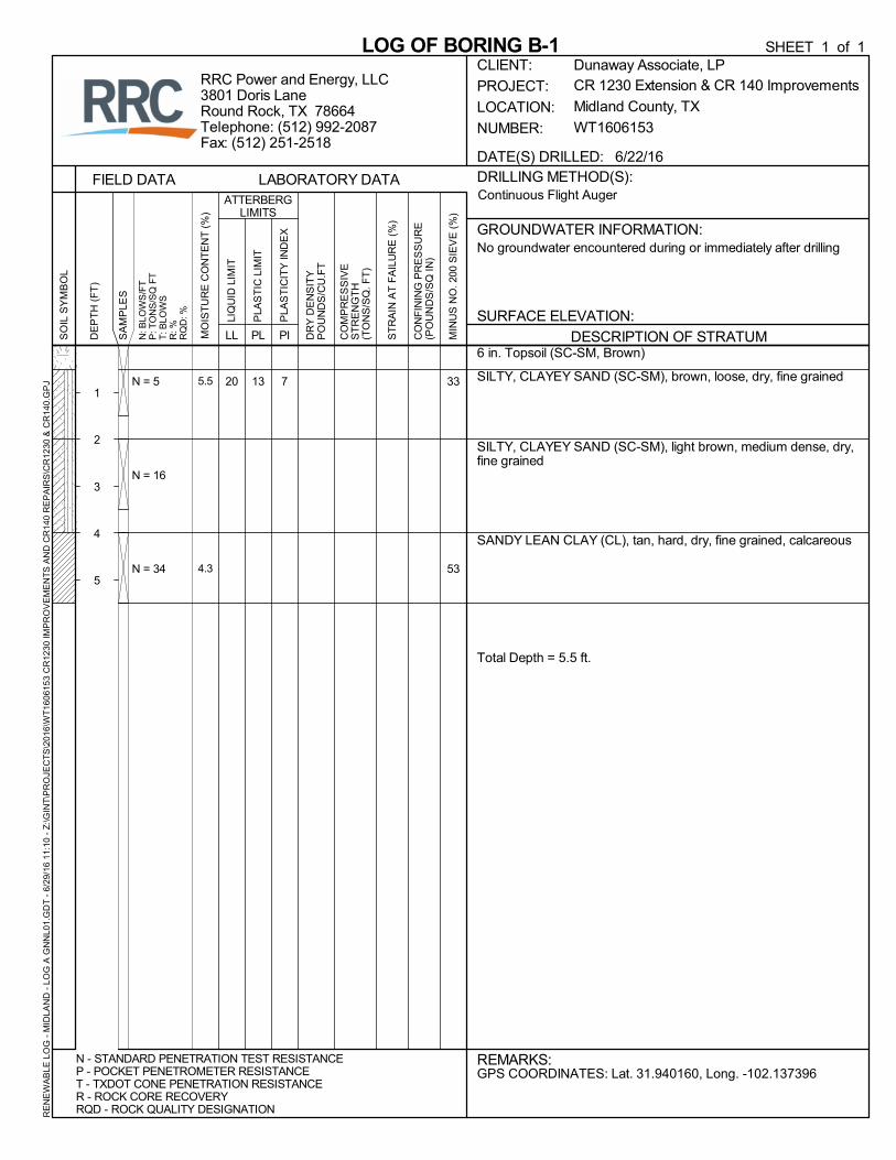
6 in. Topsoil (SC-SM, Brown)
SILTY, CLAYEY SAND (SC-SM), brown, loose, dry, fine grained
SILTY, CLAYEY SAND (SC-SM), light brown, medium dense, dry,fine grained
SANDY LEAN CLAY (CL), tan, hard, dry, fine grained, calcareous
Total Depth = 5.5 ft.
20N = 5
N = 16
N = 34
13 7 33
53
5.5
4.3
DRILLING METHOD(S):
GROUNDWATER INFORMATION:
PI
FIELD DATA
DESCRIPTION OF STRATUM
LOG OF BORING B-1S
OIL
SY
MB
OL
LL
N - STANDARD PENETRATION TEST RESISTANCEP - POCKET PENETROMETER RESISTANCET - TXDOT CONE PENETRATION RESISTANCER - ROCK CORE RECOVERYRQD - ROCK QUALITY DESIGNATION
CR 1230 Extension & CR 140 Improvements
Midland County, TX
WT1606153
REMARKS:
CLIENT:
PROJECT:
LOCATION:
NUMBER:
RRC Power and Energy, LLC3801 Doris LaneRound Rock, TX 78664Telephone: (512) 992-2087Fax: (512) 251-2518
CO
MP
RE
SS
IVE
ST
RE
NG
TH
(TO
NS
/SQ
. FT
)
GPS COORDINATES: Lat. 31.940160, Long. -102.137396
LIQ
UID
LIM
IT
DR
Y D
EN
SIT
YP
OU
ND
S/C
U.F
T
N: B
LOW
S/F
TP
: TO
NS
/SQ
FT
T: B
LOW
SR
: %R
QD
: %
ST
RA
IN A
T F
AIL
UR
E (
%)
CO
NF
ININ
G P
RE
SS
UR
E(P
OU
ND
S/S
Q IN
)
PLA
ST
IC L
IMIT
No groundwater encountered during or immediately after drilling
Continuous Flight Auger
PLA
ST
ICIT
Y IN
DE
X
MIN
US
NO
. 200
SIE
VE
(%
)
PL
DATE(S) DRILLED: 6/22/16
ATTERBERGLIMITS
SURFACE ELEVATION:
LABORATORY DATA
Dunaway Associate, LP
DE
PT
H (
FT
)
1
2
3
4
5
SA
MP
LES
MO
IST
UR
E C
ON
TE
NT
(%
)
SHEET 1 of 1R
EN
EW
AB
LE L
OG
- M
IDLA
ND
- L
OG
A G
NN
L01.
GD
T -
6/2
9/16
11
:10
- Z
:\GIN
T\P
RO
JEC
TS
\201
6\W
T16
0615
3 C
R12
30 IM
PR
OV
EM
EN
TS
AN
D C
R14
0 R
EP
AIR
S\C
R12
30 &
CR
140.
GP
J
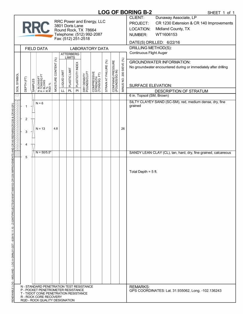
6 in. Topsoil (SM, Brown)
SILTY CLAYEY SAND (SC-SM), red, medium dense, dry, finegrained
SANDY LEAN CLAY (CL), tan, hard, dry, fine grained, calcareous
Total Depth = 5 ft.
N = 6
N = 13
N = 50/5.5"
264.8
DRILLING METHOD(S):
GROUNDWATER INFORMATION:
PI
FIELD DATA
DESCRIPTION OF STRATUM
LOG OF BORING B-2S
OIL
SY
MB
OL
LL
N - STANDARD PENETRATION TEST RESISTANCEP - POCKET PENETROMETER RESISTANCET - TXDOT CONE PENETRATION RESISTANCER - ROCK CORE RECOVERYRQD - ROCK QUALITY DESIGNATION
CR 1230 Extension & CR 140 Improvements
Midland County, TX
WT1606153
REMARKS:
CLIENT:
PROJECT:
LOCATION:
NUMBER:
RRC Power and Energy, LLC3801 Doris LaneRound Rock, TX 78664Telephone: (512) 992-2087Fax: (512) 251-2518
CO
MP
RE
SS
IVE
ST
RE
NG
TH
(TO
NS
/SQ
. FT
)
GPS COORDINATES: Lat. 31.935062, Long. -102.136243
LIQ
UID
LIM
IT
DR
Y D
EN
SIT
YP
OU
ND
S/C
U.F
T
N: B
LOW
S/F
TP
: TO
NS
/SQ
FT
T: B
LOW
SR
: %R
QD
: %
ST
RA
IN A
T F
AIL
UR
E (
%)
CO
NF
ININ
G P
RE
SS
UR
E(P
OU
ND
S/S
Q IN
)
PLA
ST
IC L
IMIT
No groundwater encountered during or immediately after drilling
Continuous Flight Auger
PLA
ST
ICIT
Y IN
DE
X
MIN
US
NO
. 200
SIE
VE
(%
)
PL
DATE(S) DRILLED: 6/22/16
ATTERBERGLIMITS
SURFACE ELEVATION:
LABORATORY DATA
Dunaway Associate, LP
DE
PT
H (
FT
)
1
2
3
4
5
SA
MP
LES
MO
IST
UR
E C
ON
TE
NT
(%
)
SHEET 1 of 1R
EN
EW
AB
LE L
OG
- M
IDLA
ND
- L
OG
A G
NN
L01.
GD
T -
6/2
9/16
11
:10
- Z
:\GIN
T\P
RO
JEC
TS
\201
6\W
T16
0615
3 C
R12
30 IM
PR
OV
EM
EN
TS
AN
D C
R14
0 R
EP
AIR
S\C
R12
30 &
CR
140.
GP
J
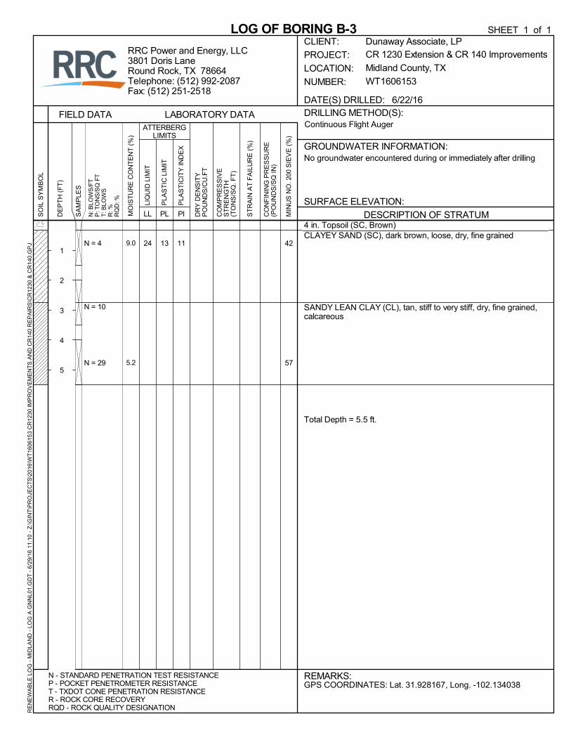
4 in. Topsoil (SC, Brown)CLAYEY SAND (SC), dark brown, loose, dry, fine grained
SANDY LEAN CLAY (CL), tan, stiff to very stiff, dry, fine grained,calcareous
Total Depth = 5.5 ft.
24N = 4
N = 10
N = 29
13 11 42
57
9.0
5.2
DRILLING METHOD(S):
GROUNDWATER INFORMATION:
PI
FIELD DATA
DESCRIPTION OF STRATUM
LOG OF BORING B-3S
OIL
SY
MB
OL
LL
N - STANDARD PENETRATION TEST RESISTANCEP - POCKET PENETROMETER RESISTANCET - TXDOT CONE PENETRATION RESISTANCER - ROCK CORE RECOVERYRQD - ROCK QUALITY DESIGNATION
CR 1230 Extension & CR 140 Improvements
Midland County, TX
WT1606153
REMARKS:
CLIENT:
PROJECT:
LOCATION:
NUMBER:
RRC Power and Energy, LLC3801 Doris LaneRound Rock, TX 78664Telephone: (512) 992-2087Fax: (512) 251-2518
CO
MP
RE
SS
IVE
ST
RE
NG
TH
(TO
NS
/SQ
. FT
)
GPS COORDINATES: Lat. 31.928167, Long. -102.134038
LIQ
UID
LIM
IT
DR
Y D
EN
SIT
YP
OU
ND
S/C
U.F
T
N: B
LOW
S/F
TP
: TO
NS
/SQ
FT
T: B
LOW
SR
: %R
QD
: %
ST
RA
IN A
T F
AIL
UR
E (
%)
CO
NF
ININ
G P
RE
SS
UR
E(P
OU
ND
S/S
Q IN
)
PLA
ST
IC L
IMIT
No groundwater encountered during or immediately after drilling
Continuous Flight Auger
PLA
ST
ICIT
Y IN
DE
X
MIN
US
NO
. 200
SIE
VE
(%
)
PL
DATE(S) DRILLED: 6/22/16
ATTERBERGLIMITS
SURFACE ELEVATION:
LABORATORY DATA
Dunaway Associate, LP
DE
PT
H (
FT
)
1
2
3
4
5
SA
MP
LES
MO
IST
UR
E C
ON
TE
NT
(%
)
SHEET 1 of 1R
EN
EW
AB
LE L
OG
- M
IDLA
ND
- L
OG
A G
NN
L01.
GD
T -
6/2
9/16
11
:10
- Z
:\GIN
T\P
RO
JEC
TS
\201
6\W
T16
0615
3 C
R12
30 IM
PR
OV
EM
EN
TS
AN
D C
R14
0 R
EP
AIR
S\C
R12
30 &
CR
140.
GP
J
6 in. Topsoil (SM, Brown)
SILTY SAND (SM), brown, very loose, dry, fine grained
SILTY, CLAYEY SAND (SC-SM), red, medium dense, dry, finegrained
SANDY LEAN CLAY (CL), tan, very stiff, dry, fine grained,calcareous
Total Depth = 9.5 ft.
21
N = 3
N = 16
N = 19
N = 21
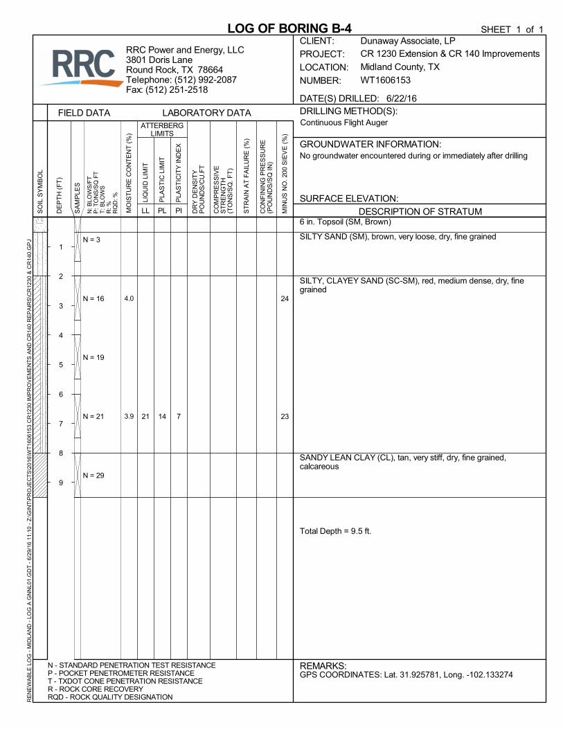
N = 29
14 7
24
23
4.0
3.9
DRILLING METHOD(S):
GROUNDWATER INFORMATION:
PI
FIELD DATA
DESCRIPTION OF STRATUM
LOG OF BORING B-4S
OIL
SY
MB
OL
LL
N - STANDARD PENETRATION TEST RESISTANCEP - POCKET PENETROMETER RESISTANCET - TXDOT CONE PENETRATION RESISTANCER - ROCK CORE RECOVERYRQD - ROCK QUALITY DESIGNATION
CR 1230 Extension & CR 140 Improvements
Midland County, TX
WT1606153
REMARKS:
CLIENT:
PROJECT:
LOCATION:
NUMBER:
RRC Power and Energy, LLC3801 Doris LaneRound Rock, TX 78664Telephone: (512) 992-2087Fax: (512) 251-2518
CO
MP
RE
SS
IVE
ST
RE
NG
TH
(TO
NS
/SQ
. FT
)
GPS COORDINATES: Lat. 31.925781, Long. -102.133274
LIQ
UID
LIM
IT
DR
Y D
EN
SIT
YP
OU
ND
S/C
U.F
T
N: B
LOW
S/F
TP
: TO
NS
/SQ
FT
T: B
LOW
SR
: %R
QD
: %
ST
RA
IN A
T F
AIL
UR
E (
%)
CO
NF
ININ
G P
RE
SS
UR
E(P
OU
ND
S/S
Q IN
)
PLA
ST
IC L
IMIT
No groundwater encountered during or immediately after drilling
Continuous Flight Auger
PLA
ST
ICIT
Y IN
DE
X
MIN
US
NO
. 200
SIE
VE
(%
)
PL
DATE(S) DRILLED: 6/22/16
ATTERBERGLIMITS
SURFACE ELEVATION:
LABORATORY DATA
Dunaway Associate, LP
DE
PT
H (
FT
)
1
2
3
4
5
6
7
8
9
SA
MP
LES
MO
IST
UR
E C
ON
TE
NT
(%
)
SHEET 1 of 1R
EN
EW
AB
LE L
OG
- M
IDLA
ND
- L
OG
A G
NN
L01.
GD
T -
6/2
9/16
11
:10
- Z
:\GIN
T\P
RO
JEC
TS
\201
6\W
T16
0615
3 C
R12
30 IM
PR
OV
EM
EN
TS
AN
D C
R14
0 R
EP
AIR
S\C
R12
30 &
CR
140.
GP
J
6 in. Topsoil (SM, Brown)
SILTY SAND (SM), brown, loose, dry, fine grained
SANDY LEAN CLAY (CL), tan, very stiff, dry, fine grained,calcareous
Total Depth = 5.5 ft.
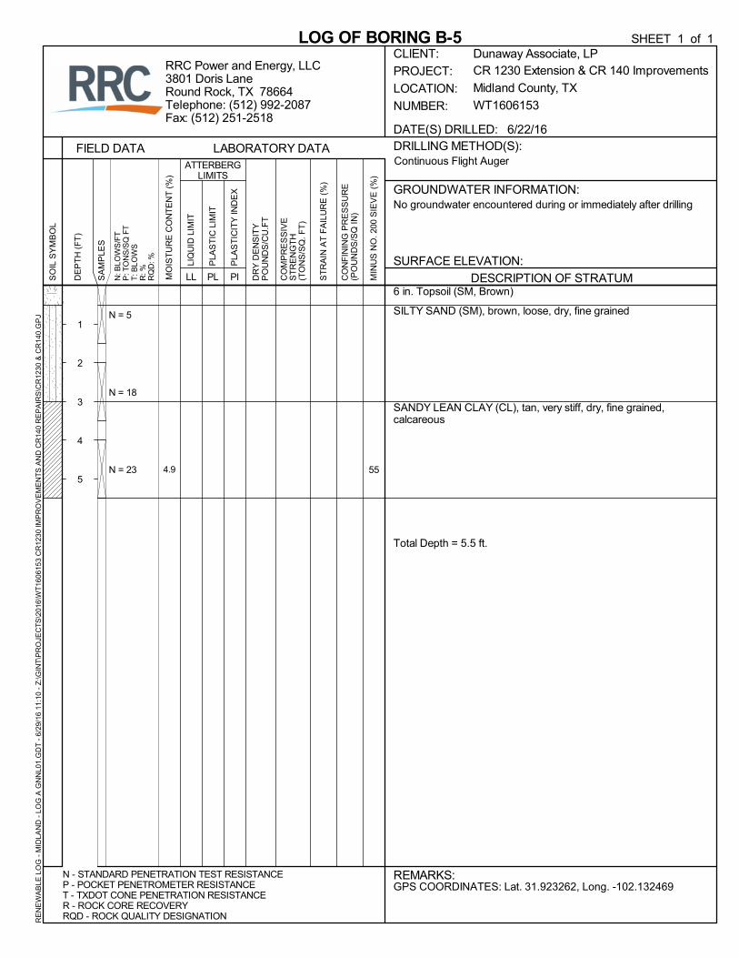
N = 5
N = 18
N = 23 554.9
DRILLING METHOD(S):
GROUNDWATER INFORMATION:
PI
FIELD DATA
DESCRIPTION OF STRATUM
LOG OF BORING B-5S
OIL
SY
MB
OL
LL
N - STANDARD PENETRATION TEST RESISTANCEP - POCKET PENETROMETER RESISTANCET - TXDOT CONE PENETRATION RESISTANCER - ROCK CORE RECOVERYRQD - ROCK QUALITY DESIGNATION
CR 1230 Extension & CR 140 Improvements
Midland County, TX
WT1606153
REMARKS:
CLIENT:
PROJECT:
LOCATION:
NUMBER:
RRC Power and Energy, LLC3801 Doris LaneRound Rock, TX 78664Telephone: (512) 992-2087Fax: (512) 251-2518
CO
MP
RE
SS
IVE
ST
RE
NG
TH
(TO
NS
/SQ
. FT
)
GPS COORDINATES: Lat. 31.923262, Long. -102.132469
LIQ
UID
LIM
IT
DR
Y D
EN
SIT
YP
OU
ND
S/C
U.F
T
N: B
LOW
S/F
TP
: TO
NS
/SQ
FT
T: B
LOW
SR
: %R
QD
: %
ST
RA
IN A
T F
AIL
UR
E (
%)
CO
NF
ININ
G P
RE
SS
UR
E(P
OU
ND
S/S
Q IN
)
PLA
ST
IC L
IMIT
No groundwater encountered during or immediately after drilling
Continuous Flight Auger
PLA
ST
ICIT
Y IN
DE
X
MIN
US
NO
. 200
SIE
VE
(%
)
PL
DATE(S) DRILLED: 6/22/16
ATTERBERGLIMITS
SURFACE ELEVATION:
LABORATORY DATA
Dunaway Associate, LP
DE
PT
H (
FT
)
1
2
3
4
5
SA
MP
LES
MO
IST
UR
E C
ON
TE
NT
(%
)
SHEET 1 of 1R
EN
EW
AB
LE L
OG
- M
IDLA
ND
- L
OG
A G
NN
L01.
GD
T -
6/2
9/16
11
:10
- Z
:\GIN
T\P
RO
JEC
TS
\201
6\W
T16
0615
3 C
R12
30 IM
PR
OV
EM
EN
TS
AN
D C
R14
0 R
EP
AIR
S\C
R12
30 &
CR
140.
GP
J
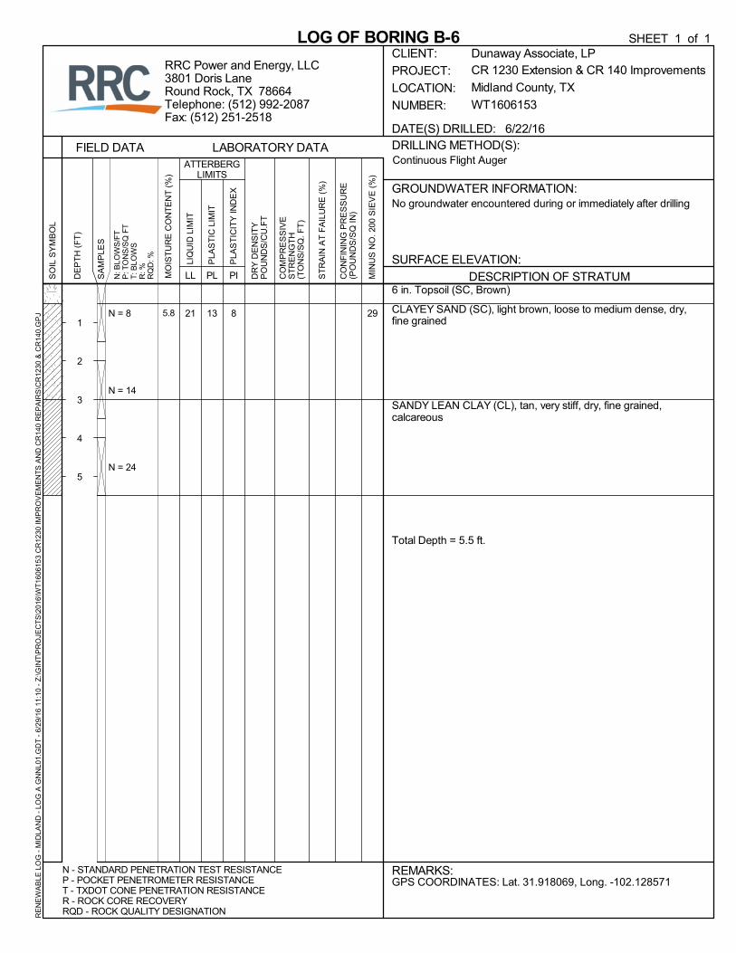
6 in. Topsoil (SC, Brown)
CLAYEY SAND (SC), light brown, loose to medium dense, dry,fine grained
SANDY LEAN CLAY (CL), tan, very stiff, dry, fine grained,calcareous
Total Depth = 5.5 ft.
21N = 8
N = 14
N = 24
13 8 295.8
DRILLING METHOD(S):
GROUNDWATER INFORMATION:
PI
FIELD DATA
DESCRIPTION OF STRATUM
LOG OF BORING B-6S
OIL
SY
MB
OL
LL
N - STANDARD PENETRATION TEST RESISTANCEP - POCKET PENETROMETER RESISTANCET - TXDOT CONE PENETRATION RESISTANCER - ROCK CORE RECOVERYRQD - ROCK QUALITY DESIGNATION
CR 1230 Extension & CR 140 Improvements
Midland County, TX
WT1606153
REMARKS:
CLIENT:
PROJECT:
LOCATION:
NUMBER:
RRC Power and Energy, LLC3801 Doris LaneRound Rock, TX 78664Telephone: (512) 992-2087Fax: (512) 251-2518
CO
MP
RE
SS
IVE
ST
RE
NG
TH
(TO
NS
/SQ
. FT
)
GPS COORDINATES: Lat. 31.918069, Long. -102.128571
LIQ
UID
LIM
IT
DR
Y D
EN
SIT
YP
OU
ND
S/C
U.F
T
N: B
LOW
S/F
TP
: TO
NS
/SQ
FT
T: B
LOW
SR
: %R
QD
: %
ST
RA
IN A
T F
AIL
UR
E (
%)
CO
NF
ININ
G P
RE
SS
UR
E(P
OU
ND
S/S
Q IN
)
PLA
ST
IC L
IMIT
No groundwater encountered during or immediately after drilling
Continuous Flight Auger
PLA
ST
ICIT
Y IN
DE
X
MIN
US
NO
. 200
SIE
VE
(%
)
PL
DATE(S) DRILLED: 6/22/16
ATTERBERGLIMITS
SURFACE ELEVATION:
LABORATORY DATA
Dunaway Associate, LP
DE
PT
H (
FT
)
1
2
3
4
5
SA
MP
LES
MO
IST
UR
E C
ON
TE
NT
(%
)
SHEET 1 of 1R
EN
EW
AB
LE L
OG
- M
IDLA
ND
- L
OG
A G
NN
L01.
GD
T -
6/2
9/16
11
:10
- Z
:\GIN
T\P
RO
JEC
TS
\201
6\W
T16
0615
3 C
R12
30 IM
PR
OV
EM
EN
TS
AN
D C
R14
0 R
EP
AIR
S\C
R12
30 &
CR
140.
GP
J

Caliche with Limestone flexible base material (12 in.)
SILTY, CLAYEY SAND (SC-SM), red, loose to medium dense,dry, fine grained
CLAYEY SAND (SC), tan, medium dense, dry, fine grained,calcareous
Total Depth = 5.5 ft.
20
N = 34
N = 6
N = 19
14 6 28
42
5.6
5.1
DRILLING METHOD(S):
GROUNDWATER INFORMATION:
PI
FIELD DATA
DESCRIPTION OF STRATUM
LOG OF BORING B-7S
OIL
SY
MB
OL
LL
N - STANDARD PENETRATION TEST RESISTANCEP - POCKET PENETROMETER RESISTANCET - TXDOT CONE PENETRATION RESISTANCER - ROCK CORE RECOVERYRQD - ROCK QUALITY DESIGNATION
CR 1230 Extension & CR 140 Improvements
Midland County, TX
WT1606153
REMARKS:
CLIENT:
PROJECT:
LOCATION:
NUMBER:
RRC Power and Energy, LLC3801 Doris LaneRound Rock, TX 78664Telephone: (512) 992-2087Fax: (512) 251-2518
CO
MP
RE
SS
IVE
ST
RE
NG
TH
(TO
NS
/SQ
. FT
)
GPS COORDINATES: Lat. 31.913457, Long. -102.126477Borehole is 70 ft. east of location designated by Dunaway
LIQ
UID
LIM
IT
DR
Y D
EN
SIT
YP
OU
ND
S/C
U.F
T
N: B
LOW
S/F
TP
: TO
NS
/SQ
FT
T: B
LOW
SR
: %R
QD
: %
ST
RA
IN A
T F
AIL
UR
E (
%)
CO
NF
ININ
G P
RE
SS
UR
E(P
OU
ND
S/S
Q IN
)
PLA
ST
IC L
IMIT
No groundwater encountered during or immediately after drilling
Continuous Flight Auger
PLA
ST
ICIT
Y IN
DE
X
MIN
US
NO
. 200
SIE
VE
(%
)
PL
DATE(S) DRILLED: 6/22/16
ATTERBERGLIMITS
SURFACE ELEVATION:
LABORATORY DATA
Dunaway Associate, LP
DE
PT
H (
FT
)
1
2
3
4
5
SA
MP
LES
MO
IST
UR
E C
ON
TE
NT
(%
)
SHEET 1 of 1R
EN
EW
AB
LE L
OG
- M
IDLA
ND
- L
OG
A G
NN
L01.
GD
T -
6/2
9/16
11
:10
- Z
:\GIN
T\P
RO
JEC
TS
\201
6\W
T16
0615
3 C
R12
30 IM
PR
OV
EM
EN
TS
AN
D C
R14
0 R
EP
AIR
S\C
R12
30 &
CR
140.
GP
J

Caliche with Limestone flexible base material (10 in.)
CLAYEY SAND (SC), brown, medium dense, dry, fine grained
SILTY, CLAYEY SAND (SC-SM), red, medium dense, dry, finegrained
Total Depth = 5.5 ft.
22
N = 40
N = 11
N = 19
13 9 35
38
6.5
7.4
DRILLING METHOD(S):
GROUNDWATER INFORMATION:
PI
FIELD DATA
DESCRIPTION OF STRATUM
LOG OF BORING B-8S
OIL
SY
MB
OL
LL
N - STANDARD PENETRATION TEST RESISTANCEP - POCKET PENETROMETER RESISTANCET - TXDOT CONE PENETRATION RESISTANCER - ROCK CORE RECOVERYRQD - ROCK QUALITY DESIGNATION
CR 1230 Extension & CR 140 Improvements
Midland County, TX
WT1606153
REMARKS:
CLIENT:
PROJECT:
LOCATION:
NUMBER:
RRC Power and Energy, LLC3801 Doris LaneRound Rock, TX 78664Telephone: (512) 992-2087Fax: (512) 251-2518
CO
MP
RE
SS
IVE
ST
RE
NG
TH
(TO
NS
/SQ
. FT
)
GPS COORDINATES: Lat. 31.915075, Long. -102.119374
LIQ
UID
LIM
IT
DR
Y D
EN
SIT
YP
OU
ND
S/C
U.F
T
N: B
LOW
S/F
TP
: TO
NS
/SQ
FT
T: B
LOW
SR
: %R
QD
: %
ST
RA
IN A
T F
AIL
UR
E (
%)
CO
NF
ININ
G P
RE
SS
UR
E(P
OU
ND
S/S
Q IN
)
PLA
ST
IC L
IMIT
No groundwater encountered during or immediately after drilling
Continuous Flight Auger
PLA
ST
ICIT
Y IN
DE
X
MIN
US
NO
. 200
SIE
VE
(%
)
PL
DATE(S) DRILLED: 6/22/16
ATTERBERGLIMITS
SURFACE ELEVATION:
LABORATORY DATA
Dunaway Associate, LP
DE
PT
H (
FT
)
1
2
3
4
5
SA
MP
LES
MO
IST
UR
E C
ON
TE
NT
(%
)
SHEET 1 of 1R
EN
EW
AB
LE L
OG
- M
IDLA
ND
- L
OG
A G
NN
L01.
GD
T -
6/2
9/16
11
:10
- Z
:\GIN
T\P
RO
JEC
TS
\201
6\W
T16
0615
3 C
R12
30 IM
PR
OV
EM
EN
TS
AN
D C
R14
0 R
EP
AIR
S\C
R12
30 &
CR
140.
GP
J

Caliche with Limestone flexible base material (1 in.)CLAYEY SAND (SC), red, medium dense, dry, fine grained
CLAYEY SAND (SC), tan, medium dense, dry, fine grained,calcareous
Total Depth = 5.5 ft.
22N = 14
N = 17
N = 25
13 9 33
44
7.0
4.7
DRILLING METHOD(S):
GROUNDWATER INFORMATION:
PI
FIELD DATA
DESCRIPTION OF STRATUM
LOG OF BORING B-9S
OIL
SY
MB
OL
LL
N - STANDARD PENETRATION TEST RESISTANCEP - POCKET PENETROMETER RESISTANCET - TXDOT CONE PENETRATION RESISTANCER - ROCK CORE RECOVERYRQD - ROCK QUALITY DESIGNATION
CR 1230 Extension & CR 140 Improvements
Midland County, TX
WT1606153
REMARKS:
CLIENT:
PROJECT:
LOCATION:
NUMBER:
RRC Power and Energy, LLC3801 Doris LaneRound Rock, TX 78664Telephone: (512) 992-2087Fax: (512) 251-2518
CO
MP
RE
SS
IVE
ST
RE
NG
TH
(TO
NS
/SQ
. FT
)
GPS COORDINATES: Lat. 31.917190, Long. -102.110364
LIQ
UID
LIM
IT
DR
Y D
EN
SIT
YP
OU
ND
S/C
U.F
T
N: B
LOW
S/F
TP
: TO
NS
/SQ
FT
T: B
LOW
SR
: %R
QD
: %
ST
RA
IN A
T F
AIL
UR
E (
%)
CO
NF
ININ
G P
RE
SS
UR
E(P
OU
ND
S/S
Q IN
)
PLA
ST
IC L
IMIT
No groundwater encountered during or immediately after drilling
Continuous Flight Auger
PLA
ST
ICIT
Y IN
DE
X
MIN
US
NO
. 200
SIE
VE
(%
)
PL
DATE(S) DRILLED: 6/22/16
ATTERBERGLIMITS
SURFACE ELEVATION:
LABORATORY DATA
Dunaway Associate, LP
DE
PT
H (
FT
)
1
2
3
4
5
SA
MP
LES
MO
IST
UR
E C
ON
TE
NT
(%
)
SHEET 1 of 1R
EN
EW
AB
LE L
OG
- M
IDLA
ND
- L
OG
A G
NN
L01.
GD
T -
6/2
9/16
11
:10
- Z
:\GIN
T\P
RO
JEC
TS
\201
6\W
T16
0615
3 C
R12
30 IM
PR
OV
EM
EN
TS
AN
D C
R14
0 R
EP
AIR
S\C
R12
30 &
CR
140.
GP
J
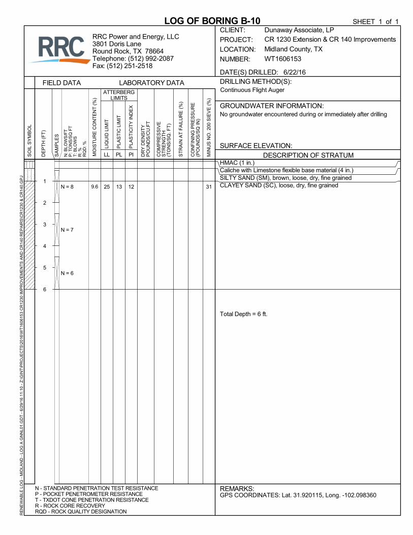
HMAC (1 in.)Caliche with Limestone flexible base material (4 in.)SILTY SAND (SM), brown, loose, dry, fine grainedCLAYEY SAND (SC), loose, dry, fine grained
Total Depth = 6 ft.
25N = 8
N = 7
N = 6
13 12 319.6
DRILLING METHOD(S):
GROUNDWATER INFORMATION:
PI
FIELD DATA
DESCRIPTION OF STRATUM
LOG OF BORING B-10S
OIL
SY
MB
OL
LL
N - STANDARD PENETRATION TEST RESISTANCEP - POCKET PENETROMETER RESISTANCET - TXDOT CONE PENETRATION RESISTANCER - ROCK CORE RECOVERYRQD - ROCK QUALITY DESIGNATION
CR 1230 Extension & CR 140 Improvements
Midland County, TX
WT1606153
REMARKS:
CLIENT:
PROJECT:
LOCATION:
NUMBER:
RRC Power and Energy, LLC3801 Doris LaneRound Rock, TX 78664Telephone: (512) 992-2087Fax: (512) 251-2518
CO
MP
RE
SS
IVE
ST
RE
NG
TH
(TO
NS
/SQ
. FT
)
GPS COORDINATES: Lat. 31.920115, Long. -102.098360
LIQ
UID
LIM
IT
DR
Y D
EN
SIT
YP
OU
ND
S/C
U.F
T
N: B
LOW
S/F
TP
: TO
NS
/SQ
FT
T: B
LOW
SR
: %R
QD
: %
ST
RA
IN A
T F
AIL
UR
E (
%)
CO
NF
ININ
G P
RE
SS
UR
E(P
OU
ND
S/S
Q IN
)
PLA
ST
IC L
IMIT
No groundwater encountered during or immediately after drilling
Continuous Flight Auger
PLA
ST
ICIT
Y IN
DE
X
MIN
US
NO
. 200
SIE
VE
(%
)
PL
DATE(S) DRILLED: 6/22/16
ATTERBERGLIMITS
SURFACE ELEVATION:
LABORATORY DATA
Dunaway Associate, LP
DE
PT
H (
FT
)
1
2
3
4
5
6
SA
MP
LES
MO
IST
UR
E C
ON
TE
NT
(%
)
SHEET 1 of 1R
EN
EW
AB
LE L
OG
- M
IDLA
ND
- L
OG
A G
NN
L01.
GD
T -
6/2
9/16
11
:10
- Z
:\GIN
T\P
RO
JEC
TS
\201
6\W
T16
0615
3 C
R12
30 IM
PR
OV
EM
EN
TS
AN
D C
R14
0 R
EP
AIR
S\C
R12
30 &
CR
140.
GP
J

PART B
STANDARD SPECIFICATIONS
100
69
Item 100
Preparing Right of Way
1. DESCRIPTION
Prepare the right of way and designated easements for construction operations by removing and disposing of all obstructions when removal of such obstructions is not specifically shown on the plans to be paid by other Items.
2. CONSTRUCTION
Protect designated features on the right of way and prune trees and shrubs as directed. Do not park equipment, service equipment, store materials, or disturb the root area under the branches of trees designated for preservation. Treat cuts on trees with an approved tree wound dressing within 20 min. of making a pruning cut or otherwise causing damage to the tree when shown on the plans. Follow all local and state regulations when burning. Pile and burn brush at approved locations as directed. Coordinate work with state and federal authorities when working in state or national forests or parks. Test, remove, and dispose of hazardous materials in accordance with Article 6.10., “Hazardous Materials.”
Clear areas shown on the plans of all obstructions, except those landscape features that are to be preserved. Such obstructions include remains of houses and other structures, foundations, floor slabs, concrete, brick, lumber, plaster, septic tank drain fields, basements, abandoned utility pipes or conduits, equipment, fences, retaining walls, and other items as specified on the plans. Remove vegetation and other landscape features not designated for preservation, curb and gutter, driveways, paved parking areas, miscellaneous stone, sidewalks, drainage structures, manholes, inlets, abandoned railroad tracks, scrap iron, and debris, whether above or below ground. Removal of live utility facilities is not included in this Item. Remove culverts, storm sewers, manholes, and inlets in proper sequence to maintain traffic and drainage.
Notify the Engineer in writing when items not shown on the plans and not reasonably detectable (buried with no obvious indication of presence) are encountered and required to be removed. These items will be handled in accordance with Article 4.5., “Differing Site Conditions.”
Remove obstructions not designated for preservation to 2 ft. below natural ground in areas receiving embankment. Remove obstructions to 2 ft. below the excavation level in areas to be excavated. Remove obstructions to 1 ft. below natural ground in all other areas. Cut trees and stumps off to ground level when allowed by the plans or directed. Plug the remaining ends of abandoned underground structures over 3 in. in diameter with concrete to form a tight closure. Backfill, compact, and restore areas where obstructions have been removed unless otherwise directed. Use approved material for backfilling. Dispose of wells in accordance with Item 103, “Disposal of Wells.”
Accept ownership, unless otherwise directed, and dispose of removed materials and debris at locations off the right of way in accordance with local, state, and federal requirements.
3. MEASUREMENT
This Item will be measured by the acre; by the 100-ft. station, regardless of the width of the right of way; or by each tree removed.
4. PAYMENT
For “acre” and “station” measurement, the work performed in accordance with this Item and measured as provided under “Measurement” will be paid for at the unit price bid for “Preparing Right of Way.” For “each”

100
70
measurement, the work performed in accordance with this Item and measured as provided under “Measurement” will be paid for at the unit price bid for “Preparing Right of Way (Tree)” of the diameter specified. This price is full compensation for pruning of designated trees and shrubs; removal and disposal of structures and obstructions; backfilling of holes; furnishing and placing concrete for plugs; and equipment, labor, tools, and incidentals.
Total payment of this Item will not exceed 10% of the original contract amount until final acceptance. The remainder will be paid on the estimate after the final acceptance under Article 5.12., “Final Acceptance.”

(THIS PAGE IS INTENTIONALLY LEFT BLANK)
110
76
Item 110
Excavation
1. DESCRIPTION
Excavate areas as shown on the plans or as directed. Remove materials encountered to the lines, grades, and typical sections shown on the plans and cross-sections.
2. CONSTRUCTION
Accept ownership of unsuitable or excess material and dispose of material in accordance with local, state, and federal regulations at locations outside the right of way.
Maintain drainage in the excavated area to avoid damage to the roadway section. Correct any damage to the subgrade caused by weather at no additional cost to the Department.
Shape slopes to avoid loosening material below or outside the proposed grades. Remove and dispose of slides as directed.
2.1. Rock Cuts. Excavate to finish subgrade. Manipulate and compact subgrade in accordance with Section 132.3.4., “Compaction Methods,” unless excavation is to clean homogenous rock at finish subgrade elevation. Use approved embankment material compacted in accordance with Section 132.3.4., “Compaction Methods,” to replace undercut material at no additional cost if excavation extends below finish subgrade.
2.2. Earth Cuts. Excavate to finish subgrade. Scarify subgrade to a uniform depth at least 6 in. below finish subgrade elevation in areas where base or pavement structure will be placed on subgrade. Manipulate and compact subgrade in accordance with Section 132.3.4., “Compaction Methods.”
Take corrective measures as directed if unsuitable material is encountered below subgrade elevations.
2.3. Subgrade Tolerances. Excavate to within 1/2 in. in cross-section and 1/2 in. in 16 ft. measured longitudinally for turnkey construction. Excavate to within 0.1 ft. in cross-section and 0.1 ft. in 16 ft. measured longitudinally for staged construction.
3. MEASUREMENT
This Item will be measured by the cubic yard in its original position as computed by the method of average end areas.
This is a plans quantity measurement Item. The quantity to be paid is the quantity shown in the proposal unless modified by Article 9.2., “Plans Quantity Measurement.” Additional measurements or calculations will be made if adjustments of quantities are required.
Limits of measurement for excavation in retaining wall areas will be as shown on the plans.
Shrinkage or swelling factors will not be considered in determining the calculated quantities.
4. PAYMENT
The work performed and materials furnished in accordance with this Item and measured as provided under “Measurement” will be paid for at the unit price bid for “Excavation (Roadway),” “Excavation (Channel),”
110
77
“Excavation (Special),” or “Excavation (Roadway and Channel).” This price is full compensation for authorized excavation; drying; undercutting subgrade and reworking or replacing the undercut material in rock cuts; hauling; disposal of material not used elsewhere on the project; scarification and compaction; and equipment, labor, materials, tools, and incidentals.
Drying required deeper than 6 in. below subgrade elevation will be paid for in accordance with Article 9.7., “Payment for Extra Work and Force Account Method.” Excavation and replacement of unsuitable material below subgrade elevations will be performed and paid for in accordance with the applicable bid items. However, if Item 132, “Embankment,” is not included in the Contract, payment for replacement of unsuitable material will be paid for in accordance with Article 9.7., “Payment for Extra Work and Force Account Method.”
When a slide not due to the Contractor’s negligence or operation occurs, payments for removal and disposal of the slide material will be in accordance with Article 9.7., “Payment for Extra Work and Force Account Method.” Excavation in backfill areas of retaining walls will not be measured or paid for directly but will be subsidiary to pertinent Items.

(THIS PAGE IS INTENTIONALLY LEFT BLANK)
216
125
Item 216
Proof Rolling
1. DESCRIPTION
Proof-roll earthwork, base, or both to locate unstable areas.
2. EQUIPMENT
2.1. Specified Equipment. Furnish rollers that weigh at least 25 tons when loaded. The maximum acceptable load is 50 tons. Provide rollers that meet the requirements of Section 210.2.4., “Pneumatic Tire Rollers.”
2.2. Alternative Equipment. The Contractor may use alternate compaction equipment that produces results equivalent to the specified equipment in the same period of time as approved. Discontinue the use of the alternative equipment and furnish the specified equipment if the desired results are not achieved.
3. CONSTRUCTION
Perform proof rolling as directed. Adjust the load and tire inflation pressures within the range of the manufacturer’s charts or tabulations, as directed. Make at least 2 coverages with the proof roller. Offset each trip of the roller by at most one tire width. Operate rollers at a speed between 2 and 6 mph, as directed. Correct unstable or nonuniform areas, if found, in accordance with the applicable Item.
4. MEASUREMENT
Rolling will be measured by the hour operated on surfaces being tested.
5. PAYMENT
The work performed and equipment furnished in accordance with this Item and measured as provided under “Measurement” will be paid for at the unit price bid for “Proof Rolling.” This price is full compensation for furnishing and operating equipment and for labor, materials, tools, and incidentals.

(THIS PAGE IS INTENTIONALLY LEFT BLANK)
247
126
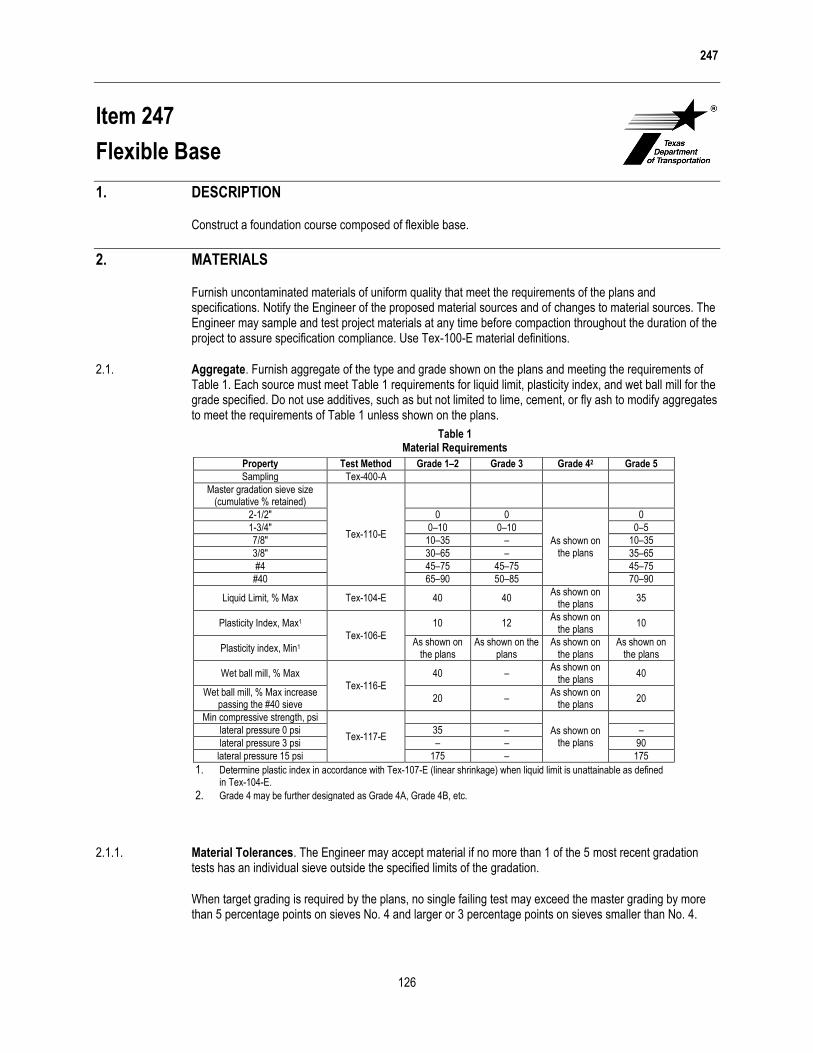
Item 247
Flexible Base
1. DESCRIPTION
Construct a foundation course composed of flexible base.
2. MATERIALS
Furnish uncontaminated materials of uniform quality that meet the requirements of the plans and specifications. Notify the Engineer of the proposed material sources and of changes to material sources. The Engineer may sample and test project materials at any time before compaction throughout the duration of the project to assure specification compliance. Use Tex-100-E material definitions.
2.1. Aggregate. Furnish aggregate of the type and grade shown on the plans and meeting the requirements of Table 1. Each source must meet Table 1 requirements for liquid limit, plasticity index, and wet ball mill for the grade specified. Do not use additives, such as but not limited to lime, cement, or fly ash to modify aggregates to meet the requirements of Table 1 unless shown on the plans.
Table 1 Material Requirements
2.1.1. Material Tolerances. The Engineer may accept material if no more than 1 of the 5 most recent gradation tests has an individual sieve outside the specified limits of the gradation.
When target grading is required by the plans, no single failing test may exceed the master grading by more than 5 percentage points on sieves No. 4 and larger or 3 percentage points on sieves smaller than No. 4.
Property Test Method Grade 1–2 Grade 3 Grade 42 Grade 5
Sampling Tex-400-A
Master gradation sieve size (cumulative % retained)
Tex-110-E
2-1/2" 0 0
As shown on the plans
0
1-3/4" 0–10 0–10 0–5
7/8" 10–35 – 10–35
3/8" 30–65 – 35–65
#4 45–75 45–75 45–75
#40 65–90 50–85 70–90
Liquid Limit, % Max Tex-104-E 40 40 As shown on
the plans 35
Plasticity Index, Max1
Tex-106-E
10 12 As shown on
the plans 10
Plasticity index, Min1 As shown on
the plans As shown on the
plans As shown on
the plans As shown on
the plans
Wet ball mill, % Max Tex-116-E
40 – As shown on
the plans 40
Wet ball mill, % Max increase passing the #40 sieve
20 – As shown on
the plans 20
Min compressive strength, psi
Tex-117-E
As shown on the plans
lateral pressure 0 psi 35 – –
lateral pressure 3 psi – – 90
lateral pressure 15 psi 175 – 175
1. Determine plastic index in accordance with Tex-107-E (linear shrinkage) when liquid limit is unattainable as defined in Tex-104-E.
2. Grade 4 may be further designated as Grade 4A, Grade 4B, etc.
247
127
The Engineer may accept material if no more than 1 of the 5 most recent plasticity index tests is outside the specified limit. No single failing test may exceed the allowable limit by more than 2 points.
2.1.2. Material Types. Do not use fillers or binders unless approved. Furnish the type specified on the plans in accordance with the following:
2.1.2.1. Type A. Crushed stone produced and graded from oversize quarried aggregate that originates from a single, naturally occurring source. Do not use gravel or multiple sources.
2.1.2.2. Type B. Crushed or uncrushed gravel. Blending of 2 or more sources is allowed.
2.1.2.3. Type C. Crushed gravel with a minimum of 60% of the particles retained on a No. 4 sieve with 2 or more crushed faces as determined by Tex-460-A, Part I. Blending of 2 or more sources is allowed.
2.1.2.4. Type D. Type A material or crushed concrete. Crushed concrete containing gravel will be considered Type D material. Crushed concrete must meet the requirements in Section 247.2.1.3.2., “Recycled Material (Including Crushed Concrete) Requirements,” and be managed in a way to provide for uniform quality. The Engineer may require separate dedicated stockpiles in order to verify compliance.
2.1.2.5. Type E. Caliche, iron ore or as otherwise shown on the plans.
2.1.3. Recycled Material. Reclaimed asphalt pavement (RAP) and other recycled materials may be used when shown on the plans. Request approval to blend 2 or more sources of recycled materials.
2.1.3.1. Limits on Percentage. Do not exceed 20% RAP by weight, when RAP is allowed, unless otherwise shown on the plans. The percentage limitations for other recycled materials will be as shown on the plans.
2.1.3.2. Recycled Material (Including Crushed Concrete) Requirements.
2.1.3.2.1. Contractor-Furnished Recycled Materials. Provide recycled materials, other than RAP, that have a maximum sulfate content of 3,000 ppm when tested in accordance with Tex-145-E. When the Contractor furnishes the recycled materials, including crushed concrete, the final product will be subject to the requirements of Table 1 for the grade specified. Certify compliance with DMS-11000, “Evaluating and Using Nonhazardous Recyclable Materials Guidelines,” for Contractor furnished recycled materials. In addition, recycled materials must be free from reinforcing steel and other objectionable material and have at most 1.5% deleterious material when tested in accordance with Tex-413-A. For RAP, do not exceed a maximum percent loss from decantation of 5.0% when tested in accordance with Tex-406-A. Test RAP without removing the asphalt.
2.1.3.2.2. Department-Furnished Required Recycled Materials. When the Department furnishes and requires the use of recycled materials, unless otherwise shown on the plans:
Department-required recycled material will not be subject to the requirements in Table 1,
Contractor-furnished materials are subject to the requirements in Table 1 and this Item,
the final product, blended, will be subject to the requirements in Table 1, and
for final product, unblended (100% Department-furnished required recycled material), the liquid limit,
plasticity index, wet ball mill, and compressive strength is waived.
Crush Department-furnished RAP so that 100% passes the 2 in. sieve. The Contractor is responsible for uniformly blending to meet the percentage required.
2.1.3.2.3. Department-Furnished and Allowed Recycled Materials. When the Department furnishes and allows the use of recycled materials or allows the Contractor to furnish recycled materials, the final blended product is subject to the requirements of Table 1 and the plans.
247
128
2.1.3.3. Recycled Material Sources. Department-owned recycled material is available to the Contractor only when shown on the plans. Return unused Department-owned recycled materials to the Department stockpile location designated by the Engineer unless otherwise shown on the plans.
The use of Contractor-owned recycled materials is allowed when shown on the plans. Contractor-owned surplus recycled materials remain the property of the Contractor. Remove Contractor-owned recycled materials from the project and dispose of them in accordance with federal, state, and local regulations before project acceptance. Do not intermingle Contractor-owned recycled material with Department-owned recycled material unless approved.
2.2. Water. Furnish water free of industrial wastes and other objectionable matter.
2.3. Material Sources. Expose the vertical faces of all strata of material proposed for use when non-commercial sources are used. Secure and process the material by successive vertical cuts extending through all exposed strata, when directed.
3. EQUIPMENT
Provide machinery, tools, and equipment necessary for proper execution of the work.
3.1. Provide rollers in accordance with Item 210, “Rolling.” Provide proof rollers in accordance with Item 216, “Proof Rolling,” when required.
3.2. When ride quality measurement is required, provide a high speed or lightweight inertial profiler certified at the Texas A&M Transportation Institute. Provide equipment certification documentation. Display a current decal on the equipment indicating the certification expiration date.
4. CONSTRUCTION
Construct each layer uniformly, free of loose or segregated areas, and with the required density and moisture content. Provide a smooth surface that conforms to the typical sections, lines, and grades shown on the plans or as directed.
Stockpile base material temporarily at an approved location before delivery to the roadway. Build stockpiles in layers no greater than 2 ft. thick. Stockpiles must have a total height between 10 and 16 ft. unless otherwise approved. After construction and acceptance of the stockpile, loading from the stockpile for delivery is allowed. Load by making successive vertical cuts through the entire depth of the stockpile.
Do not add or remove material from temporary stockpiles that require sampling and testing before delivery unless otherwise approved. Charges for additional sampling and testing required as a result of adding or removing material will be deducted from the Contractor’s estimates.
Haul approved flexible base in clean trucks. Deliver the required quantity to each 100-ft. station or designated stockpile site as shown on the plans. Prepare stockpile sites as directed. When delivery is to the 100-ft. station, manipulate in accordance with the applicable Items.
4.1. Preparation of Subgrade or Existing Base. Remove or scarify existing asphalt concrete pavement in accordance with Item 105, “Removing Treated and Untreated Base and Asphalt Pavement,” when shown on the plans or as directed. Shape the subgrade or existing base to conform to the typical sections shown on the plans or as directed.
When new base is required to be mixed with existing base, deliver, place, and spread the new flexible base in the required amount per station. Manipulate and thoroughly mix the new base with existing material to provide a uniform mixture to the specified depth before shaping.
247
129
Proof roll the roadbed in accordance with Item 216, “Proof Rolling,” before pulverizing or scarifying when shown on the plans or directed. Correct soft spots as directed.
4.2. Placing. Spread and shape flexible base into a uniform layer with an approved spreader the same day as delivered unless otherwise approved. Construct layers to the thickness shown on the plans. Maintain the shape of the course. Control dust by sprinkling, as directed. Correct or replace segregated areas as directed, at no additional expense to the Department.
Place successive base courses and finish courses using the same construction methods required for the first course.
4.3. Compaction. Compact using density control unless otherwise shown on the plans. Multiple lifts are permitted when shown on the plans or approved. Bring each layer to the moisture content directed. When necessary, sprinkle the material in accordance with Item 204, “Sprinkling.”
Begin rolling longitudinally at the sides and proceed towards the center, overlapping on successive trips by at least 1/2 the width of the roller unit. Begin rolling at the low side and progress toward the high side on superelevated curves. Offset alternate trips of the roller. Operate rollers at a speed between 2 and 6 mph as directed.
Rework, recompact, and refinish material that fails to meet or that loses required moisture, density, stability, or finish requirements before the next course is placed or the project is accepted. Continue work until specification requirements are met. Perform the work at no additional expense to the Department.
Before final acceptance, the Engineer will select the locations of tests and measure the flexible base depth in accordance with Tex-140-E. Correct areas deficient by more than 1/2 in. in thickness by scarifying, adding material as required, reshaping, recompacting, and refinishing at the Contractor’s expense.
4.3.1. Ordinary Compaction. Roll with approved compaction equipment as directed. Correct irregularities, depressions, and weak spots immediately by scarifying the areas affected, adding or removing approved material as required, reshaping, and recompacting.
4.3.2. Density Control. Compact to at least 100% of the maximum dry density determined by Tex-113-E, unless otherwise shown on the plans. Maintain moisture during compaction within ±2 percentage points of the optimum moisture content as determined by Tex-113-E. Measure the moisture content of the material in accordance with Tex-115-E or Tex-103-E during compaction daily and report the results the same day to the Engineer, unless otherwise shown on the plans or directed. Do not achieve density by drying the material after compaction.
The Engineer will determine roadway density and moisture content of completed sections in accordance with Tex-115-E. The Engineer may accept the section if no more than 1 of the 5 most recent density tests is below the specified density and the failing test is no more than 3 pcf below the specified density.
4.4. Finishing. After completing compaction, clip, skin, or tight-blade the surface with a maintainer or subgrade trimmer to a depth of approximately 1/4 in. Remove loosened material and dispose of it at an approved location. Seal the clipped surface immediately by rolling with a pneumatic tire roller until a smooth surface is attained. Add small increments of water as needed during rolling. Shape and maintain the course and surface in conformity with the typical sections, lines, and grades as shown on the plans or as directed.
Correct grade deviations greater than 1/4 in. in 16 feet measured longitudinally or greater than 1/4 in. over the entire width of the cross-section in areas where surfacing is to be placed. Correct by loosening and adding, or removing material. Reshape and re-compact in accordance with Section 247.4.3., “Compaction.”
4.5. Curing. Cure the finished section until the moisture content is at least 2 percentage points below optimum or as directed before applying the next successive course or prime coat.

247
130
4.6. Ride Quality. This section applies to the final travel lanes that receive a 1 or 2 course surface treatment for the final surface, unless otherwise shown on the plans. Measure ride quality of the base course after placement of the prime coat and before placement of the surface treatment, unless otherwise approved. Use a certified profiler operator from the Department’s MPL. When requested, furnish the Engineer documentation for the person certified to operate the profiler.
Provide all profile measurements to the Engineer in electronic data files within 3 days after placement of the prime coat using the format specified in Tex-1001-S. The Engineer will use Department software to evaluate longitudinal profiles to determine areas requiring corrective action. Correct 0.1-mi.sections having an average international roughness index (IRI) value greater than 100.0 in. per mile to an IRI value of 100.0 in. per mile or less for each wheel path, unless otherwise shown on the plans.
Re-profile and correct sections that fail to maintain ride quality until placement of the next course, as directed. Correct re-profiled sections until specification requirements are met, as approved. Perform this work at no additional expense to the Department.
5. MEASUREMENT
Flexible base will be measured as follows:
Flexible Base (Complete In Place). The ton, square yard, or any cubic yard method.
Flexible Base (Roadway Delivery). The ton or any cubic yard method.
Flexible Base (Stockpile Delivery). The ton, cubic yard in vehicle, or cubic yard in stockpile.
Measurement by the cubic yard in final position and square yard is a plans quantity measurement. The quantity to be paid for is the quantity shown in the proposal unless modified by Article 9.2., “Plans Quantity Measurement.” Additional measurements or calculations will be made if adjustments of quantities are required.
Measurement is further defined for payment as follows.
5.1. Cubic Yard in Vehicle. By the cubic yard in vehicles of uniform capacity at the point of delivery.
5.2. Cubic Yard in Stockpile. By the cubic yard in the final stockpile position by the method of average end areas.
5.3. Cubic Yard in Final Position. By the cubic yard in the completed and accepted final position. The volume of base course is computed in place by the method of average end areas between the original subgrade or existing base surfaces and the lines, grades, and slopes of the accepted base course as shown on the plans.
5.4. Square Yard. By the square yard of surface area in the completed and accepted final position. The surface area of the base course is based on the width of flexible base as shown on the plans.
5.5. Ton. By the ton of dry weight in vehicles as delivered. The dry weight is determined by deducting the weight of the moisture in the material at the time of weighing from the gross weight of the material. The Engineer will determine the moisture content in the material in accordance with Tex-103-E from samples taken at the time of weighing.
When material is measured in trucks, the weight of the material will be determined on certified scales, or the Contractor must provide a set of standard platform truck scales at a location approved by the Engineer. Scales must conform to the requirements of Item 520, “Weighing and Measuring Equipment.”
6. PAYMENT
The work performed and materials furnished in accordance with this Item and measured as provided under “Measurement” will be paid for at the unit price bid for the types of work shown below. No additional payment
247
131
will be made for thickness or width exceeding that shown on the typical section or provided on the plans for cubic yard in the final position or square yard measurement.
Sprinkling and rolling, except proof rolling, will not be paid for directly but will be subsidiary to this Item unless otherwise shown on the plans. When proof rolling is shown on the plans or directed, it will be paid for in accordance with Item 216, “Proof Rolling.”
Where subgrade is constructed under this Contract, correction of soft spots in the subgrade will be at the Contractor’s expense. Where subgrade is not constructed under this Contract, correction of soft spots in the subgrade will be paid in accordance with pertinent Items or Article 4.4., “Changes in the Work.”
6.1. Flexible Base (Complete In Place). Payment will be made for the type and grade specified. For cubic yard measurement, “In Vehicle,” “In Stockpile,” or “In Final Position” will be specified. For square yard measurement, a depth will be specified. This price is full compensation for furnishing materials, temporary stockpiling, assistance provided in stockpile sampling and operations to level stockpiles for measurement, loading, hauling, delivery of materials, spreading, blading, mixing, shaping, placing, compacting, reworking, finishing, correcting locations where thickness is deficient, curing, furnishing scales and labor for weighing and measuring, and equipment, labor, tools, and incidentals.
6.2. Flexible Base (Roadway Delivery). Payment will be made for the type and grade specified. For cubic yard measurement, “In Vehicle,” “In Stockpile,” or “In Final Position” will be specified. The unit price bid will not include processing at the roadway. This price is full compensation for furnishing materials, temporary stockpiling, assistance provided in stockpile sampling and operations to level stockpiles for measurement, loading, hauling, delivery of materials, furnishing scales and labor for weighing and measuring, and equipment, labor, tools, and incidentals.
6.3. Flexible Base (Stockpile Delivery). Payment will be made for the type and grade specified. For cubic yard measurement, “In Vehicle” or “In Stockpile” will be specified. The unit price bid will not include processing at the roadway. This price is full compensation for furnishing and disposing of materials, preparing the stockpile area, temporary or permanent stockpiling, assistance provided in stockpile sampling and operations to level stockpiles for measurement, loading, hauling, delivery of materials to the stockpile, furnishing scales and labor for weighing and measuring, and equipment, labor, tools, and incidentals.

(THIS PAGE IS INTENTIONALLY LEFT BLANK)

300
173
Item 300
Asphalts, Oils, and Emulsions
1. DESCRIPTION
Provide asphalt cements, cutback and emulsified asphalts, performance-graded asphalt binders, and other miscellaneous asphalt materials as specified on the plans.
2. MATERIALS
Provide asphalt materials that meet the stated requirements when tested in accordance with the referenced Department, AASHTO, and ASTM test methods. Use asphalt containing recycled materials only if the recycled components meet the requirements of Article 6.9, “Recycled Materials.” Provide asphalt materials that have been preapproved for use by the Construction Division in accordance with Tex-545-C, “Asphalt Binder Quality Program.”
Acronyms used in this Item are defined in Table 1.
Table 1 Acronyms
Acronym Definition
Test Procedure Designations
Tex Department T or R AASHTO D ASTM
Polymer Modifier Designations
P polymer-modified SBR or L styrene-butadiene rubber (latex) SBS styrene-butadiene-styrene block co-polymer TR tire rubber (from ambient temperature grinding of truck and
passenger tires)
AC asphalt cement
AE asphalt emulsion
AE-P asphalt emulsion prime
A-R asphalt-rubber
C cationic
EAP&T emulsified asphalt prime and tack
H-suffix harder residue (lower penetration)
HF high float
MC medium-curing
MS medium-setting
PCE prime, cure, and erosion control
PG performance grade
RC rapid-curing
RS rapid-setting
S-suffix stockpile usage
SCM special cutback material
SS slow-setting
300
174
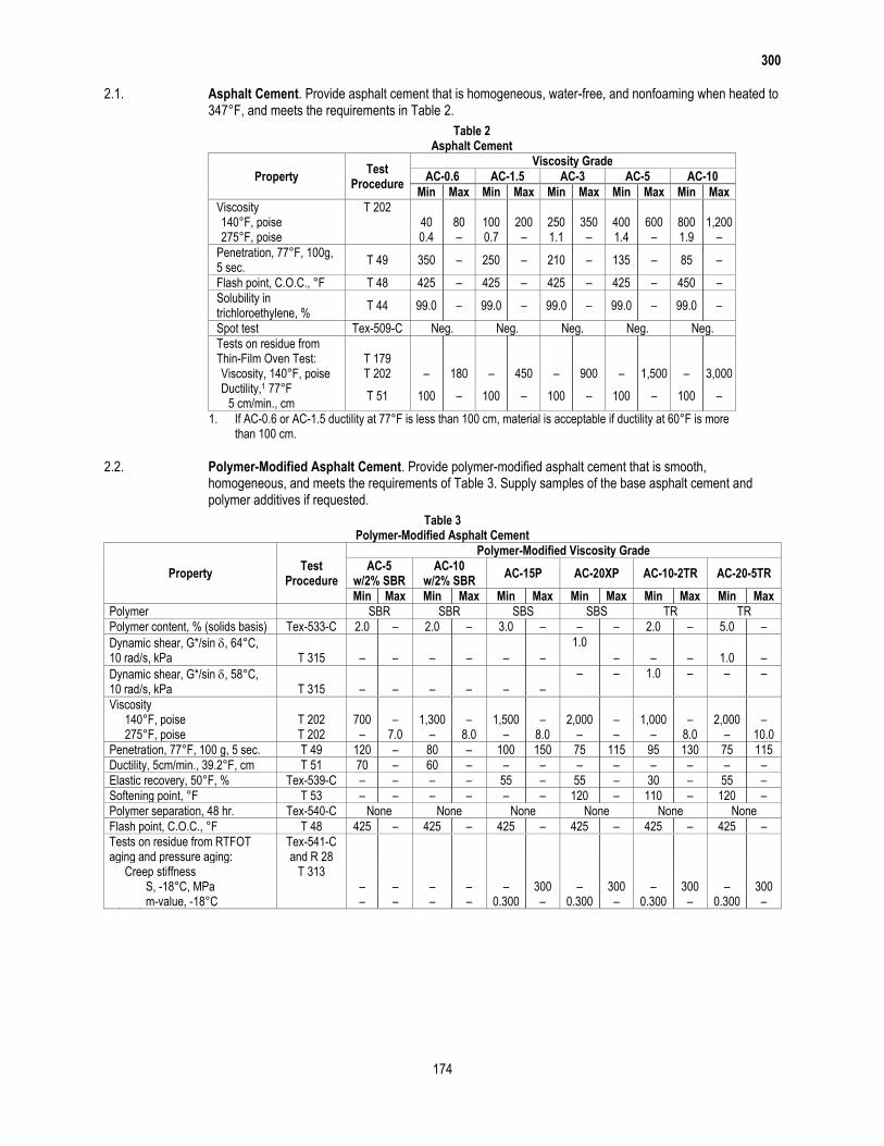
2.1. Asphalt Cement. Provide asphalt cement that is homogeneous, water-free, and nonfoaming when heated to 347°F, and meets the requirements in Table 2.
Table 2 Asphalt Cement
Property Test
Procedure
Viscosity Grade
AC-0.6 AC-1.5 AC-3 AC-5 AC-10
Min Max Min Max Min Max Min Max Min Max
Viscosity T 202 140°F, poise 40 80 100 200 250 350 400 600 800 1,200 275°F, poise 0.4 – 0.7 – 1.1 – 1.4 – 1.9 –
Penetration, 77°F, 100g, 5 sec.
T 49 350 – 250 – 210 – 135 – 85 –
Flash point, C.O.C., °F T 48 425 – 425 – 425 – 425 – 450 –
Solubility in trichloroethylene, %
T 44 99.0 – 99.0 – 99.0 – 99.0 – 99.0 –
Spot test Tex-509-C Neg. Neg. Neg. Neg. Neg.
Tests on residue from Thin-Film Oven Test: T 179
Viscosity, 140°F, poise T 202 – 180 – 450 – 900 – 1,500 – 3,000 Ductility,1 77°F
T 51 100 – 100 – 100 – 100 – 100 – 5 cm/min., cm
1. If AC-0.6 or AC-1.5 ductility at 77°F is less than 100 cm, material is acceptable if ductility at 60°F is more than 100 cm.
2.2. Polymer-Modified Asphalt Cement. Provide polymer-modified asphalt cement that is smooth, homogeneous, and meets the requirements of Table 3. Supply samples of the base asphalt cement and polymer additives if requested.
Table 3 Polymer-Modified Asphalt Cement
Property Test
Procedure
Polymer-Modified Viscosity Grade
AC-5 w/2% SBR
AC-10 w/2% SBR
AC-15P AC-20XP AC-10-2TR AC-20-5TR
Min Max Min Max Min Max Min Max Min Max Min Max
Polymer SBR SBR SBS SBS TR TR
Polymer content, % (solids basis) Tex-533-C 2.0 – 2.0 – 3.0 – – – 2.0 – 5.0 –
Dynamic shear, G*/sin , 64°C, 10 rad/s, kPa T 315 – – – – – –
1.0
– – – 1.0 –
Dynamic shear, G*/sin , 58°C, 10 rad/s, kPa T 315 – – – – – –
– – 1.0 – – –
Viscosity 140°F, poise T 202 700 – 1,300 – 1,500 – 2,000 – 1,000 – 2,000 – 275°F, poise T 202 – 7.0 – 8.0 – 8.0 – – – 8.0 – 10.0
Penetration, 77°F, 100 g, 5 sec. T 49 120 – 80 – 100 150 75 115 95 130 75 115
Ductility, 5cm/min., 39.2°F, cm T 51 70 – 60 – – – – – – – – –
Elastic recovery, 50°F, % Tex-539-C – – – – 55 – 55 – 30 – 55 –
Softening point, °F T 53 – – – – – – 120 – 110 – 120 –
Polymer separation, 48 hr. Tex-540-C None None None None None None
Flash point, C.O.C., °F T 48 425 – 425 – 425 – 425 – 425 – 425 –
Tests on residue from RTFOT aging and pressure aging:
Tex-541-C and R 28
Creep stiffness T 313 S, -18°C, MPa – – – – – 300 – 300 – 300 – 300 m-value, -18°C – – – – 0.300 – 0.300 – 0.300 – 0.300 –
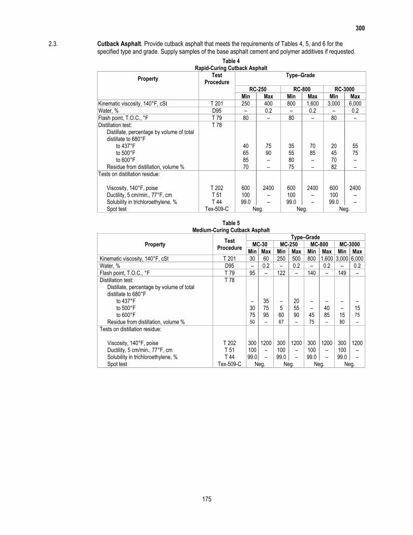
300
175
2.3. Cutback Asphalt. Provide cutback asphalt that meets the requirements of Tables 4, 5, and 6 for the specified type and grade. Supply samples of the base asphalt cement and polymer additives if requested.
Table 4 Rapid-Curing Cutback Asphalt
Property Test
Procedure Type–Grade
RC-250 RC-800 RC-3000
Min Max Min Max Min Max
Kinematic viscosity, 140°F, cSt T 201 250 400 800 1,600 3,000 6,000
Water, % D95 – 0.2 – 0.2 – 0.2
Flash point, T.O.C., °F T 79 80 – 80 – 80 –
Distillation test: T 78 Distillate, percentage by volume of total
distillate to 680°F to 437°F 40 75 35 70 20 55 to 500°F 65 90 55 85 45 75 to 600°F 85 – 80 – 70 – Residue from distillation, volume % 70 – 75 – 82 –
Tests on distillation residue: Viscosity, 140°F, poise T 202 600 2400 600 2400 600 2400 Ductility, 5 cm/min., 77°F, cm T 51 100 – 100 – 100 – Solubility in trichloroethylene, % T 44 99.0 – 99.0 – 99.0 – Spot test Tex-509-C Neg. Neg. Neg.
Table 5
Medium-Curing Cutback Asphalt
Property Test
Procedure
Type–Grade
MC-30 MC-250 MC-800 MC-3000
Min Max Min Max Min Max Min Max
Kinematic viscosity, 140°F, cSt T 201 30 60 250 500 800 1,600 3,000 6,000
Water, % D95 – 0.2 – 0.2 – 0.2 – 0.2
Flash point, T.O.C., °F T 79 95 – 122 – 140 – 149 –
Distillation test: T 78
Distillate, percentage by volume of total distillate to 680°F
to 437°F – 35 – 20 – – – – to 500°F 30 75 5 55 – 40 – 15 to 600°F 75 95 60 90 45 85 15 75
Residue from distillation, volume % 50 – 67 – 75 – 80 –
Tests on distillation residue: Viscosity, 140°F, poise T 202 300 1200 300 1200 300 1200 300 1200 Ductility, 5 cm/min., 77°F, cm T 51 100 – 100 – 100 – 100 – Solubility in trichloroethylene, % T 44 99.0 – 99.0 – 99.0 – 99.0 – Spot test Tex-509-C Neg. Neg. Neg. Neg.
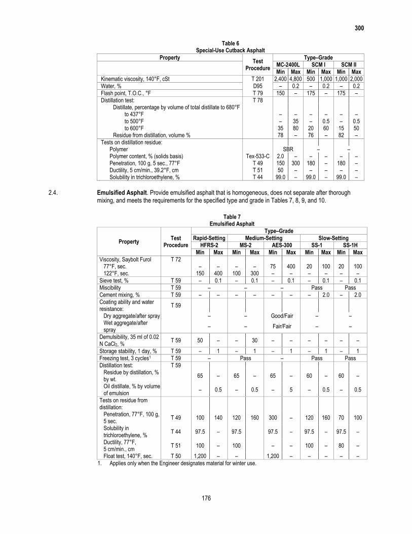
300
176
Table 6 Special-Use Cutback Asphalt
Property Test
Procedure
Type–Grade
MC-2400L SCM I SCM II
Min Max Min Max Min Max
Kinematic viscosity, 140°F, cSt T 201 2,400 4,800 500 1,000 1,000 2,000
Water, % D95 – 0.2 – 0.2 – 0.2
Flash point, T.O.C., °F T 79 150 – 175 – 175 –
Distillation test: T 78 Distillate, percentage by volume of total distillate to 680°F to 437°F – – – – – – to 500°F – 35 – 0.5 – 0.5 to 600°F 35 80 20 60 15 50 Residue from distillation, volume % 78 – 76 – 82 –
Tests on distillation residue: Polymer SBR – – Polymer content, % (solids basis) Tex-533-C 2.0 – – – – – Penetration, 100 g, 5 sec., 77°F T 49 150 300 180 – 180 – Ductility, 5 cm/min., 39.2°F, cm T 51 50 – – – – – Solubility in trichloroethylene, % T 44 99.0 – 99.0 – 99.0 –
2.4. Emulsified Asphalt. Provide emulsified asphalt that is homogeneous, does not separate after thorough mixing, and meets the requirements for the specified type and grade in Tables 7, 8, 9, and 10.
Table 7
Emulsified Asphalt
Property Test
Procedure
Type–Grade
Rapid-Setting Medium-Setting Slow-Setting
HFRS-2 MS-2 AES-300 SS-1 SS-1H
Min Max Min Max Min Max Min Max Min Max
Viscosity, Saybolt Furol T 72 77°F, sec. – – – – 75 400 20 100 20 100 122°F, sec. 150 400 100 300 – – – – – –
Sieve test, % T 59 – 0.1 – 0.1 – 0.1 – 0.1 – 0.1
Miscibility T 59 – – – Pass Pass
Cement mixing, % T 59 – – – – – – – 2.0 – 2.0
Coating ability and water resistance:
T 59
Dry aggregate/after spray – – Good/Fair – – Wet aggregate/after
spray – – Fair/Fair – –
Demulsibility, 35 ml of 0.02 N CaCl2, %
T 59 50 – – 30 – – – – – –
Storage stability, 1 day, % T 59 – 1 – 1 – 1 – 1 – 1
Freezing test, 3 cycles1 T 59 – Pass – Pass Pass
Distillation test: T 59 Residue by distillation, %
by wt. 65 – 65 – 65 – 60 – 60 –
Oil distillate, % by volume of emulsion
– 0.5 – 0.5 – 5 – 0.5 – 0.5
Tests on residue from distillation:
Penetration, 77°F, 100 g, 5 sec.
T 49 100 140 120 160 300 – 120 160 70 100
Solubility in trichloroethylene, %
T 44 97.5 – 97.5 97.5 – 97.5 – 97.5 –
Ductility, 77°F, 5 cm/min., cm
T 51 100 – 100 – – 100 – 80 –
Float test, 140°F, sec. T 50 1,200 – – 1,200 – – – – –
1. Applies only when the Engineer designates material for winter use.
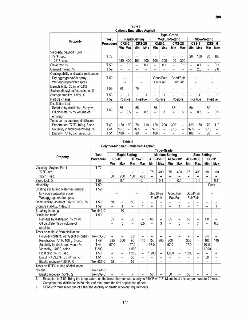
300
177
Table 8 Cationic Emulsified Asphalt
Property Test
Procedure
Type–Grade
Rapid-Setting Medium-Setting Slow-Setting
CRS-2 CRS-2H CMS-2 CMS-2S CSS-1 CSS-1H
Min Max Min Max Min Max Min Max Min Max Min Max
Viscosity, Saybolt Furol T 72
77°F, sec. – – – – – – – – 20 100 20 100 122°F, sec. 150 400 150 400 100 300 100 300 – – – –
Sieve test, % T 59 – 0.1 – 0.1 – 0.1 – 0.1 – 0.1 – 0.1
Cement mixing, % T 59 – – – – – – – – – 2.0 – 2.0
Coating ability and water resistance: T 59
Dry aggregate/after spray – – Good/Fair Good/Fair – – Wet aggregate/after spray – – Fair/Fair Fair/Fair – –
Demulsibility, 35 ml of 0.8% Sodium dioctyl sulfosuccinate, %
T 59 70 – 70 – – – – – – – – –
Storage stability, 1 day, % T 59 – 1 – 1 – 1 – 1 – 1 – 1
Particle charge T 59 Positive Positive Positive Positive Positive Positive
Distillation test:
T 59
Residue by distillation, % by wt. 65 – 65 – 65 – 65 – 60 – 60 – Oil distillate, % by volume of
emulsion – 0.5 – 0.5 – 7 – 5 – 0.5 – 0.5
Tests on residue from distillation: Penetration, 77°F, 100 g, 5 sec. T 49 120 160 70 110 120 200 300 – 120 160 70 110 Solubility in trichloroethylene, % T 44 97.5 – 97.5 – 97.5 – 97.5 – 97.5 – 97.5 – Ductility, 77°F, 5 cm/min., cm T 51 100 – 80 – 100 – – – 100 – 80 –
Table 9
Polymer-Modified Emulsified Asphalt
Property Test
Procedure
Type–Grade
Rapid-Setting Medium-Setting Slow-Setting
RS-1P HFRS-2P AES-150P AES-300P AES-300S SS-1P
Min Max Min Max Min Max Min Max Min Max Min Max
Viscosity, Saybolt Furol T 72 77°F, sec. – – – – 75 400 75 400 75 400 30 100 122°F, sec. 50 200 150 400 – – – – – – – –
Sieve test, % T 59 – 0.1 – 0.1 – 0.1 – 0.1 – 0.1 – 0.1
Miscibility T 59 – – – – – Pass
Coating ability and water resistance: T 59 Dry aggregate/after spray – – Good/Fair Good/Fair Good/Fair – Wet aggregate/after spray – – Fair/Fair Fair/Fair Fair/Fair –
Demulsibility, 35 ml of 0.02 N CaCl2, % T 59 60 – 50 – – – – – – – – –
Storage stability, 1 day, % T 59 – 1 – 1 – 1 – 1 – 1 – 1
Breaking index, g Tex-542-C – 80 – – – – – – – – – –
Distillation test:1 T 59 Residue by distillation, % by wt. 65 – 65 – 65 – 65 – 65 – 60 – Oil distillate, % by volume of
emulsion – 3 – 0.5 – 3 – 5 – 7 – 0.5
Tests on residue from distillation: Polymer content, wt. % (solids basis) Tex-533-C – – 3.0 – – – – – – – 3.0 – Penetration, 77°F, 100 g, 5 sec. T 49 225 300 90 140 150 300 300 – 300 – 100 140 Solubility in trichloroethylene, % T 44 97.0 – 97.0 – 97.0 – 97.0 – 97.0 – 97.0 – Viscosity, 140°F, poise T 202 – – 1,500 – – – – – – – 1,300 – Float test, 140°F, sec. T 50 – – 1,200 – 1,200 – 1,200 – 1,200 – – – Ductility,2 39.2°F, 5 cm/min., cm T 51 – – 50 – – – – – – – 50 – Elastic recovery,2 50°F, % Tex-539-C 55 – 55 – – – – – – – – –
Tests on RTFO curing of distillation residue Tex-541-C Elastic recovery, 50°F, % Tex-539-C – – – – 50 – 50 – 30 – – –
1. Exception to T 59: Bring the temperature on the lower thermometer slowly to 350°F ±10°F. Maintain at this temperature for 20 min. Complete total distillation in 60 min. (±5 min.) from the first application of heat.
2. HFRS-2P must meet one of either the ductility or elastic recovery requirements.
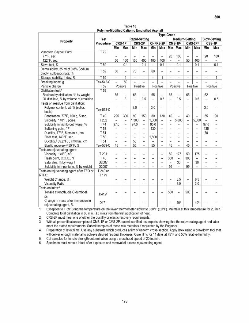
300
178
Table 10 Polymer-Modified Cationic Emulsified Asphalt
Property Test
Procedure
Type-Grade
Rapid-Setting Medium-Setting Slow-Setting
CRS-1P CRS-2P CHFRS-2P CMS-1P3 CMS-2P3 CSS-1P
Min Max Min Max Min Max Min Max Min Max Min Max
Viscosity, Saybolt Furol T 72 77°F, sec. – – – – – – 20 100 – – 20 100 122°F, sec. 50 150 150 400 100 400 – – 50 400 – –
Sieve test, % T 59 – 0.1 – 0.1 – 0.1 – 0.1 – 0.1 – 0.1
Demulsibility, 35 ml of 0.8% Sodium dioctyl sulfosuccinate, %
T 59 60 – 70 – 60 – – – – – – –
Storage stability, 1 day, % T 59 – 1 – 1 – 1 – – – – – 1
Breaking index, g Tex-542-C – 80 – – – – – – – – – –
Particle charge T 59 Positive Positive Positive Positive Positive Positive
Distillation test:1 T 59 Residue by distillation, % by weight 65 – 65 – 65 – 65 – 65 – 62 – Oil distillate, % by volume of emulsion – 3 – 0.5 – 0.5 – 0.5 – 0.5 – 0.5
Tests on residue from distillation: Polymer content, wt. % (solids
basis) Tex-533-C
– – 3.0 – 3.0 – – – – – 3.0 –
Penetration, 77°F, 100 g, 5 sec. T 49 225 300 90 150 80 130 40 – 40 – 55 90 Viscosity, 140°F, poise T 202 – – 1,300 – 1,300 – – 5,000 – 5,000 – – Solubility in trichloroethylene, % T 44 97.0 – 97.0 – 95.0 – – – – – 97.0 – Softening point, °F T 53 – – – – 130 – – – – – 135 – Ductility, 77°F, 5 cm/min., cm T 51 – – – – – – – – – – 70 – Float test, 140°F, sec. T 50 – – – – 1,800 – – – – – Ductility,2 39.2°F, 5 cm/min., cm T 51 – – 50 – – – – – – – – – Elastic recovery,2 50°F, % Tex-539-C 45 – 55 – 55 – 45 – 45 – – –
Tests on rejuvenating agent: Viscosity, 140°F, cSt T 201 – – – – – – 50 175 50 175 – – Flash point, C.O.C., °F T 48 – – – – – – 380 – 380 – – – Saturates, % by weight D2007 – – – – – – – 30 – 30 – – Solubility in n-pentane, % by weight D2007 – – – – – – 99 – 99 – – –
Tests on rejuvenating agent after TFO or RTFO:
T 240 or T 179
Weight Change, % – – – – – – – 6.5 – 6.5 – – Viscosity Ratio – – – – – – – 3.0 – 3.0 – –
Tests on latex:4 Tensile strength, die C dumbbell,
psi D4125 – – – – – – 500 – 500 – – –
Change in mass after immersion in rejuvenating agent, %
D471 – – – – – – – 406 – 406 – –
1. Exception to T 59: Bring the temperature on the lower thermometer slowly to 350°F (±0°F). Maintain at this temperature for 20 min. Complete total distillation in 60 min. (±5 min.) from the first application of heat.
2. CRS-2P must meet one of either the ductility or elastic recovery requirements. 3. With all precertification samples of CMS-1P or CMS-2P, submit certified test reports showing that the rejuvenating agent and latex
meet the stated requirements. Submit samples of these raw materials if requested by the Engineer. 4. Preparation of latex films: Use any substrate which produces a film of uniform cross-section. Apply latex using a drawdown tool that
will deliver enough material to achieve desired residual thickness. Cure films for 14 days at 75°F and 50% relative humidity. 5. Cut samples for tensile strength determination using a crosshead speed of 20 in./min. 6. Specimen must remain intact after exposure and removal of excess rejuvenating agent.
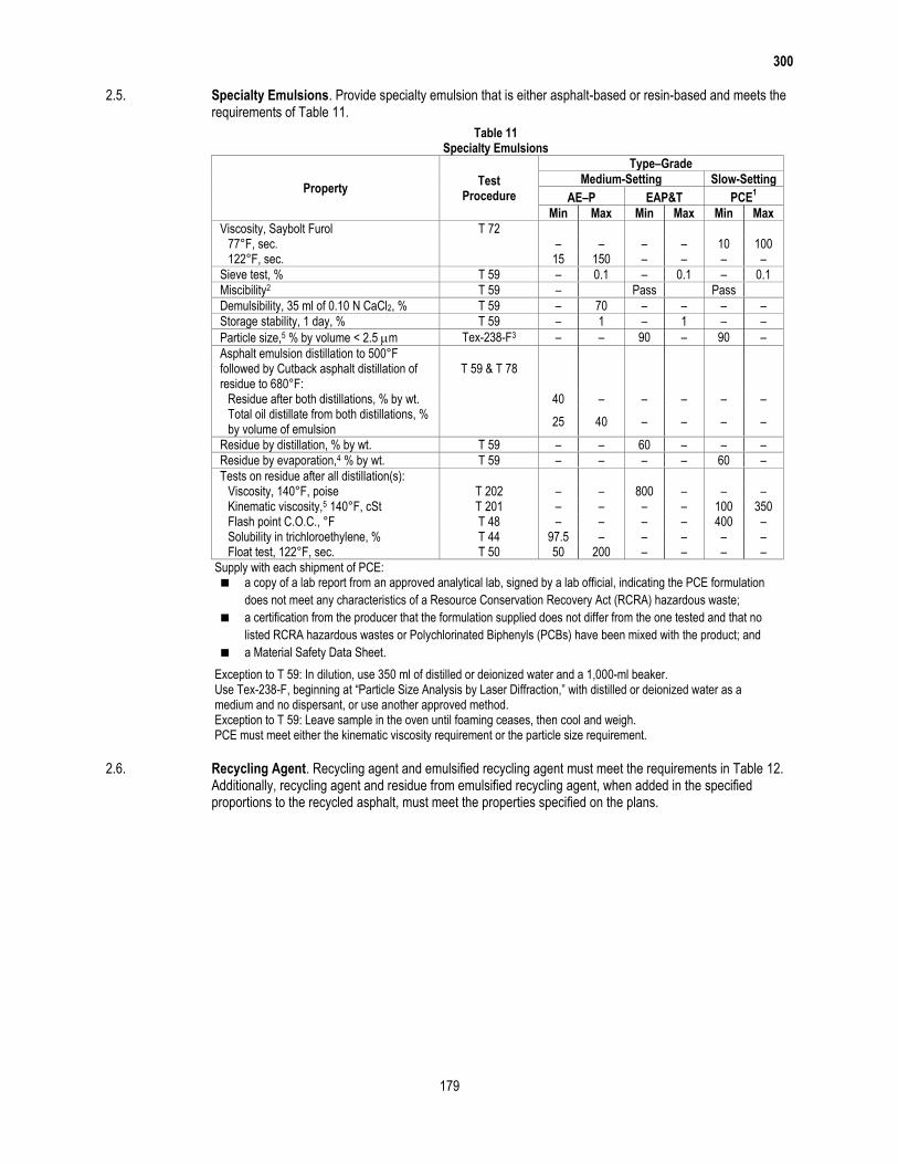
300
179
2.5. Specialty Emulsions. Provide specialty emulsion that is either asphalt-based or resin-based and meets the requirements of Table 11.
Table 11 Specialty Emulsions
Property Test
Procedure
Type–Grade
Medium-Setting Slow-Setting
AE–P EAP&T PCE1
Min Max Min Max Min Max
Viscosity, Saybolt Furol T 72 77°F, sec. – – – – 10 100 122°F, sec. 15 150 – – – –
Sieve test, % T 59 – 0.1 – 0.1 – 0.1
Miscibility2 T 59 – Pass Pass
Demulsibility, 35 ml of 0.10 N CaCl2, % T 59 – 70 – – – –
Storage stability, 1 day, % T 59 – 1 – 1 – –
Particle size,5 % by volume < 2.5 m Tex-238-F3 – – 90 – 90 –
Asphalt emulsion distillation to 500°F followed by Cutback asphalt distillation of residue to 680°F:
T 59 & T 78
Residue after both distillations, % by wt. 40 – – – – – Total oil distillate from both distillations, %
by volume of emulsion 25 40 – – – –
Residue by distillation, % by wt. T 59 – – 60 – – –
Residue by evaporation,4 % by wt. T 59 – – – – 60 –
Tests on residue after all distillation(s): Viscosity, 140°F, poise T 202 – – 800 – – – Kinematic viscosity,5 140°F, cSt T 201 – – – – 100 350 Flash point C.O.C., °F T 48 – – – – 400 – Solubility in trichloroethylene, % T 44 97.5 – – – – – Float test, 122°F, sec. T 50 50 200 – – – –
1. Supply with each shipment of PCE: a copy of a lab report from an approved analytical lab, signed by a lab official, indicating the PCE formulation
does not meet any characteristics of a Resource Conservation Recovery Act (RCRA) hazardous waste;
a certification from the producer that the formulation supplied does not differ from the one tested and that no
listed RCRA hazardous wastes or Polychlorinated Biphenyls (PCBs) have been mixed with the product; and
a Material Safety Data Sheet.
2. Exception to T 59: In dilution, use 350 ml of distilled or deionized water and a 1,000-ml beaker. 3. Use Tex-238-F, beginning at “Particle Size Analysis by Laser Diffraction,” with distilled or deionized water as a
medium and no dispersant, or use another approved method. 4. Exception to T 59: Leave sample in the oven until foaming ceases, then cool and weigh. 5. PCE must meet either the kinematic viscosity requirement or the particle size requirement.
2.6. Recycling Agent. Recycling agent and emulsified recycling agent must meet the requirements in Table 12. Additionally, recycling agent and residue from emulsified recycling agent, when added in the specified proportions to the recycled asphalt, must meet the properties specified on the plans.
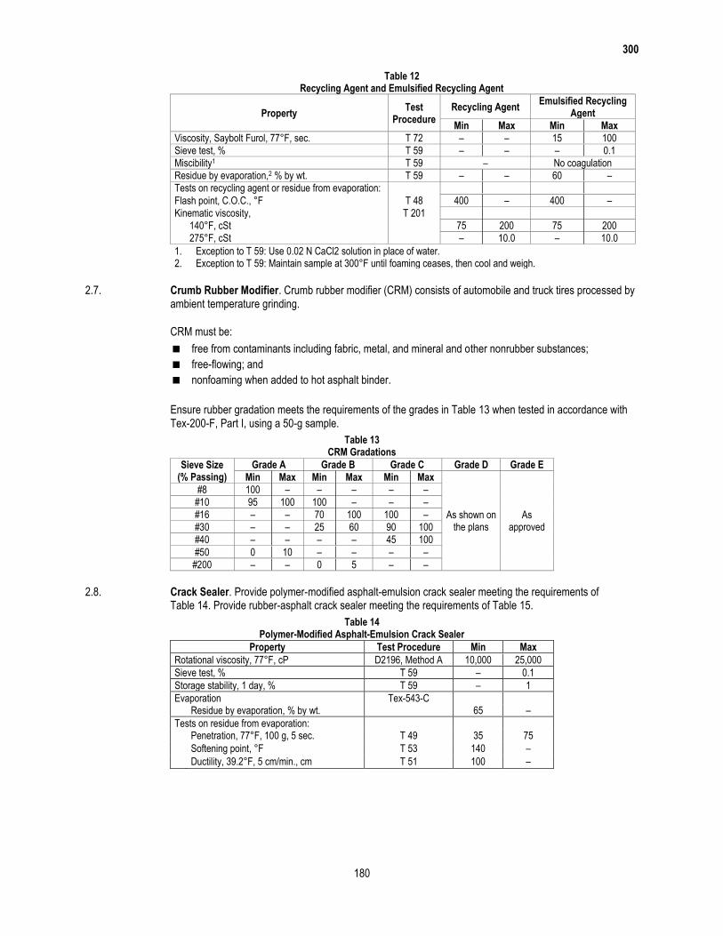
300
180
Table 12 Recycling Agent and Emulsified Recycling Agent
Property Test
Procedure Recycling Agent
Emulsified Recycling Agent
Min Max Min Max
Viscosity, Saybolt Furol, 77°F, sec. T 72 – – 15 100
Sieve test, % T 59 – – – 0.1
Miscibility1 T 59 – No coagulation
Residue by evaporation,2 % by wt. T 59 – – 60 –
Tests on recycling agent or residue from evaporation:
Flash point, C.O.C., °F T 48 400 – 400 –
Kinematic viscosity, T 201
140°F, cSt 75 200 75 200
275°F, cSt – 10.0 – 10.0
1. Exception to T 59: Use 0.02 N CaCl2 solution in place of water. 2. Exception to T 59: Maintain sample at 300°F until foaming ceases, then cool and weigh.
2.7. Crumb Rubber Modifier. Crumb rubber modifier (CRM) consists of automobile and truck tires processed by ambient temperature grinding.
CRM must be:
free from contaminants including fabric, metal, and mineral and other nonrubber substances;
free-flowing; and
nonfoaming when added to hot asphalt binder.
Ensure rubber gradation meets the requirements of the grades in Table 13 when tested in accordance with Tex-200-F, Part I, using a 50-g sample.
Table 13 CRM Gradations
Sieve Size (% Passing)
Grade A Grade B Grade C Grade D Grade E
Min Max Min Max Min Max
As shown on the plans
As approved
#8 100 – – – – –
#10 95 100 100 – – –
#16 – – 70 100 100 –
#30 – – 25 60 90 100
#40 – – – – 45 100
#50 0 10 – – – –
#200 – – 0 5 – –
2.8. Crack Sealer. Provide polymer-modified asphalt-emulsion crack sealer meeting the requirements of Table 14. Provide rubber-asphalt crack sealer meeting the requirements of Table 15.
Table 14 Polymer-Modified Asphalt-Emulsion Crack Sealer
Property Test Procedure Min Max
Rotational viscosity, 77°F, cP D2196, Method A 10,000 25,000
Sieve test, % T 59 – 0.1
Storage stability, 1 day, % T 59 – 1
Evaporation Tex-543-C Residue by evaporation, % by wt. 65 –
Tests on residue from evaporation: Penetration, 77°F, 100 g, 5 sec. T 49 35 75
Softening point, °F T 53 140 –
Ductility, 39.2°F, 5 cm/min., cm T 51 100 –
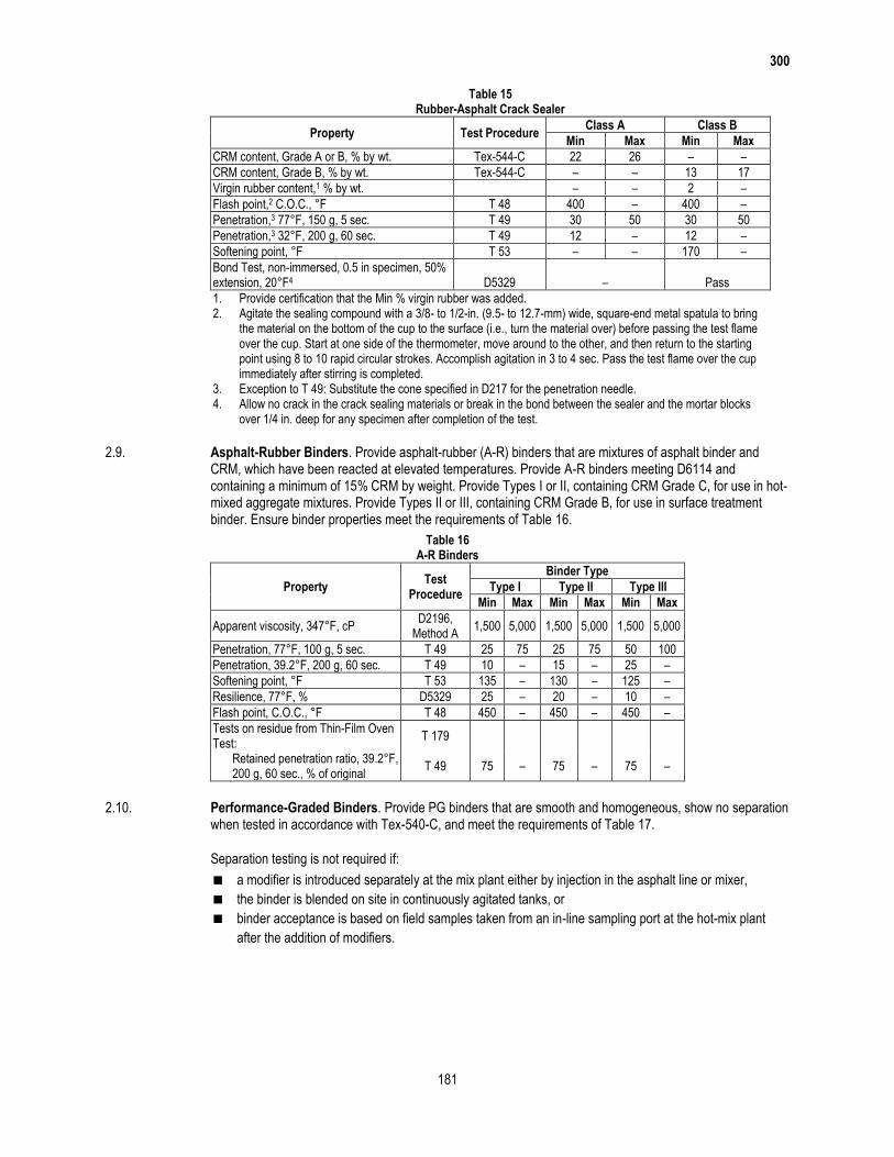
300
181
Table 15 Rubber-Asphalt Crack Sealer
Property Test Procedure Class A Class B
Min Max Min Max
CRM content, Grade A or B, % by wt. Tex-544-C 22 26 – –
CRM content, Grade B, % by wt. Tex-544-C – – 13 17
Virgin rubber content,1 % by wt. – – 2 –
Flash point,2 C.O.C., °F T 48 400 – 400 –
Penetration,3 77°F, 150 g, 5 sec. T 49 30 50 30 50
Penetration,3 32°F, 200 g, 60 sec. T 49 12 – 12 –
Softening point, °F T 53 – – 170 –
Bond Test, non-immersed, 0.5 in specimen, 50% extension, 20°F4 D5329 – Pass
1. Provide certification that the Min % virgin rubber was added. 2. Agitate the sealing compound with a 3/8- to 1/2-in. (9.5- to 12.7-mm) wide, square-end metal spatula to bring
the material on the bottom of the cup to the surface (i.e., turn the material over) before passing the test flame over the cup. Start at one side of the thermometer, move around to the other, and then return to the starting point using 8 to 10 rapid circular strokes. Accomplish agitation in 3 to 4 sec. Pass the test flame over the cup immediately after stirring is completed.
3. Exception to T 49: Substitute the cone specified in D217 for the penetration needle. 4. Allow no crack in the crack sealing materials or break in the bond between the sealer and the mortar blocks
over 1/4 in. deep for any specimen after completion of the test.
2.9. Asphalt-Rubber Binders. Provide asphalt-rubber (A-R) binders that are mixtures of asphalt binder and CRM, which have been reacted at elevated temperatures. Provide A-R binders meeting D6114 and containing a minimum of 15% CRM by weight. Provide Types I or II, containing CRM Grade C, for use in hot-mixed aggregate mixtures. Provide Types II or III, containing CRM Grade B, for use in surface treatment binder. Ensure binder properties meet the requirements of Table 16.
Table 16 A-R Binders
Property Test
Procedure
Binder Type
Type I Type II Type III
Min Max Min Max Min Max
Apparent viscosity, 347°F, cP D2196,
Method A 1,500 5,000 1,500 5,000 1,500 5,000
Penetration, 77°F, 100 g, 5 sec. T 49 25 75 25 75 50 100
Penetration, 39.2°F, 200 g, 60 sec. T 49 10 – 15 – 25 –
Softening point, °F T 53 135 – 130 – 125 –
Resilience, 77°F, % D5329 25 – 20 – 10 –
Flash point, C.O.C., °F T 48 450 – 450 – 450 –
Tests on residue from Thin-Film Oven Test:
T 179
Retained penetration ratio, 39.2°F, 200 g, 60 sec., % of original
T 49 75 – 75 – 75 –
2.10. Performance-Graded Binders. Provide PG binders that are smooth and homogeneous, show no separation when tested in accordance with Tex-540-C, and meet the requirements of Table 17.
Separation testing is not required if:
a modifier is introduced separately at the mix plant either by injection in the asphalt line or mixer,
the binder is blended on site in continuously agitated tanks, or
binder acceptance is based on field samples taken from an in-line sampling port at the hot-mix plant
after the addition of modifiers.
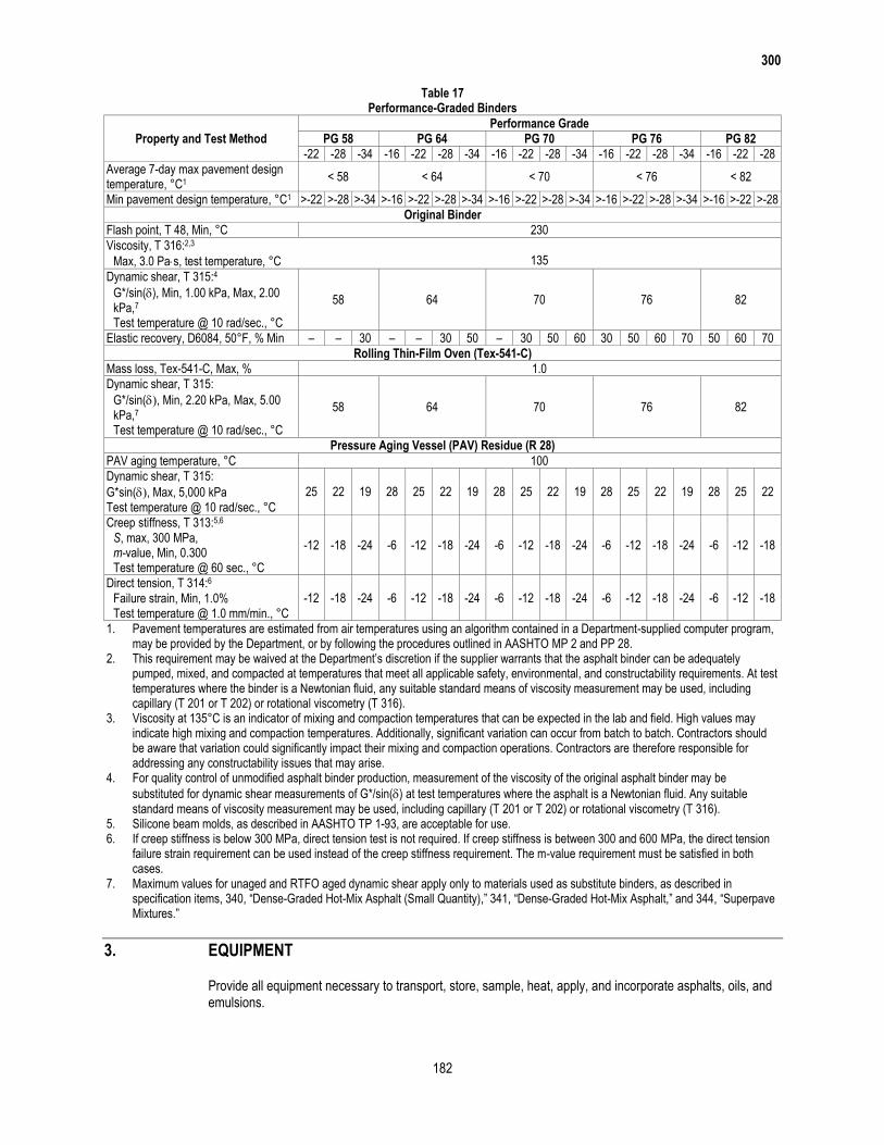
300
182
Table 17 Performance-Graded Binders
Property and Test Method
Performance Grade
PG 58 PG 64 PG 70 PG 76 PG 82
-22 -28 -34 -16 -22 -28 -34 -16 -22 -28 -34 -16 -22 -28 -34 -16 -22 -28
Average 7-day max pavement design temperature, °C1
< 58 < 64 < 70 < 76 < 82
Min pavement design temperature, °C1 >-22 >-28 >-34 >-16 >-22 >-28 >-34 >-16 >-22 >-28 >-34 >-16 >-22 >-28 >-34 >-16 >-22 >-28
Original Binder
Flash point, T 48, Min, °C 230
Viscosity, T 316:2,3 Max, 3.0 Pas, test temperature, °C 135
Dynamic shear, T 315:4
58 64 70 76 82 G*/sin(), Min, 1.00 kPa, Max, 2.00
kPa,7 Test temperature @ 10 rad/sec., °C
Elastic recovery, D6084, 50°F, % Min – – 30 – – 30 50 – 30 50 60 30 50 60 70 50 60 70
Rolling Thin-Film Oven (Tex-541-C)
Mass loss, Tex-541-C, Max, % 1.0
Dynamic shear, T 315:
58 64 70 76 82 G*/sin(, Min, 2.20 kPa, Max, 5.00
kPa,7 Test temperature @ 10 rad/sec., °C
Pressure Aging Vessel (PAV) Residue (R 28)
PAV aging temperature, °C 100
Dynamic shear, T 315:
25 22 19 28 25 22 19 28 25 22 19 28 25 22 19 28 25 22 G*sin(, Max, 5,000 kPa Test temperature @ 10 rad/sec., °C
Creep stiffness, T 313:5,6
-12 -18 -24 -6 -12 -18 -24 -6 -12 -18 -24 -6 -12 -18 -24 -6 -12 -18 S, max, 300 MPa,
m-value, Min, 0.300 Test temperature @ 60 sec., °C
Direct tension, T 314:6 -12 -18 -24 -6 -12 -18 -24 -6 -12 -18 -24 -6 -12 -18 -24 -6 -12 -18 Failure strain, Min, 1.0%
Test temperature @ 1.0 mm/min., °C
1. Pavement temperatures are estimated from air temperatures using an algorithm contained in a Department-supplied computer program, may be provided by the Department, or by following the procedures outlined in AASHTO MP 2 and PP 28.
2. This requirement may be waived at the Department’s discretion if the supplier warrants that the asphalt binder can be adequately pumped, mixed, and compacted at temperatures that meet all applicable safety, environmental, and constructability requirements. At test temperatures where the binder is a Newtonian fluid, any suitable standard means of viscosity measurement may be used, including capillary (T 201 or T 202) or rotational viscometry (T 316).
3. Viscosity at 135°C is an indicator of mixing and compaction temperatures that can be expected in the lab and field. High values may indicate high mixing and compaction temperatures. Additionally, significant variation can occur from batch to batch. Contractors should be aware that variation could significantly impact their mixing and compaction operations. Contractors are therefore responsible for addressing any constructability issues that may arise.
4. For quality control of unmodified asphalt binder production, measurement of the viscosity of the original asphalt binder may be
substituted for dynamic shear measurements of G*/sin() at test temperatures where the asphalt is a Newtonian fluid. Any suitable standard means of viscosity measurement may be used, including capillary (T 201 or T 202) or rotational viscometry (T 316).
5. Silicone beam molds, as described in AASHTO TP 1-93, are acceptable for use. 6. If creep stiffness is below 300 MPa, direct tension test is not required. If creep stiffness is between 300 and 600 MPa, the direct tension
failure strain requirement can be used instead of the creep stiffness requirement. The m-value requirement must be satisfied in both cases.
7. Maximum values for unaged and RTFO aged dynamic shear apply only to materials used as substitute binders, as described in specification items, 340, “Dense-Graded Hot-Mix Asphalt (Small Quantity),” 341, “Dense-Graded Hot-Mix Asphalt,” and 344, “Superpave Mixtures.”
3. EQUIPMENT
Provide all equipment necessary to transport, store, sample, heat, apply, and incorporate asphalts, oils, and emulsions.
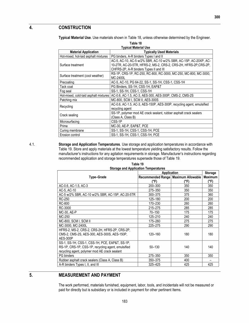
300
183
4. CONSTRUCTION
Typical Material Use. Use materials shown in Table 18, unless otherwise determined by the Engineer.
Table 18 Typical Material Use
Material Application Typically Used Materials
Hot-mixed, hot-laid asphalt mixtures PG binders, A-R binders Types I and II
Surface treatment AC-5, AC-10, AC-5 w/2% SBR, AC-10 w/2% SBR, AC-15P, AC-20XP, AC-10-2TR, AC-20-5TR, HFRS-2, MS-2, CRS-2, CRS-2H, HFRS-2P,CRS-2P, CHFRS-2P, A-R binders Types II and III
Surface treatment (cool weather) RS-1P, CRS-1P, RC-250, RC-800, RC-3000, MC-250, MC-800, MC-3000, MC-2400L
Precoating AC-5, AC-10, PG 64-22, SS-1, SS-1H, CSS-1, CSS-1H
Tack coat PG Binders, SS-1H, CSS-1H, EAP&T
Fog seal SS-1, SS-1H, CSS-1, CSS-1H
Hot-mixed, cold-laid asphalt mixtures AC-0.6, AC-1.5, AC-3, AES-300, AES-300P, CMS-2, CMS-2S
Patching mix MC-800, SCM I, SCM II, AES-300S
Recycling AC-0.6, AC-1.5, AC-3, AES-150P, AES-300P, recycling agent, emulsified recycling agent
Crack sealing SS-1P, polymer mod AE crack sealant, rubber asphalt crack sealers (Class A, Class B)
Microsurfacing CSS-1P
Prime MC-30, AE-P, EAP&T, PCE
Curing membrane SS-1, SS-1H, CSS-1, CSS-1H, PCE
Erosion control SS-1, SS-1H, CSS-1, CSS-1H, PCE
4.1. Storage and Application Temperatures. Use storage and application temperatures in accordance with Table 19. Store and apply materials at the lowest temperature yielding satisfactory results. Follow the manufacturer’s instructions for any agitation requirements in storage. Manufacturer’s instructions regarding recommended application and storage temperatures supersede those of Table 19.
Table 19 Storage and Application Temperatures
Type–Grade
Application Storage Maximum
(°F) Recommended Range
(°F) Maximum Allowable
(°F)
AC-0.6, AC-1.5, AC-3 200–300 350 350
AC-5, AC-10 275–350 350 350
AC-5 w/2% SBR, AC-10 w/2% SBR, AC-15P, AC-20-5TR 300–375 375 360
RC-250 125–180 200 200
RC-800 170–230 260 260
RC-3000 215–275 285 285
MC-30, AE-P 70–150 175 175
MC-250 125–210 240 240
MC-800, SCM I, SCM II 175–260 275 275
MC-3000, MC-2400L 225–275 290 290
HFRS-2, MS-2, CRS-2, CRS-2H, HFRS-2P, CRS-2P, CMS-2, CMS-2S, AES-300, AES-300S, AES-150P, AES-300P
120–160 180 180
SS-1, SS-1H, CSS-1, CSS-1H, PCE, EAP&T, SS-1P, RS-1P, CRS-1P, CSS-1P, recycling agent, emulsified recycling agent, polymer mod AE crack sealant
50–130 140 140
PG binders 275–350 350 350
Rubber asphalt crack sealers (Class A, Class B) 350–375 400 –
A-R binders Types I, II, and III 325–425 425 425
5. MEASUREMENT AND PAYMENT
The work performed, materials furnished, equipment, labor, tools, and incidentals will not be measured or paid for directly but is subsidiary or is included in payment for other pertinent Items.

(THIS PAGE IS INTENTIONALLY LEFT BLANK)
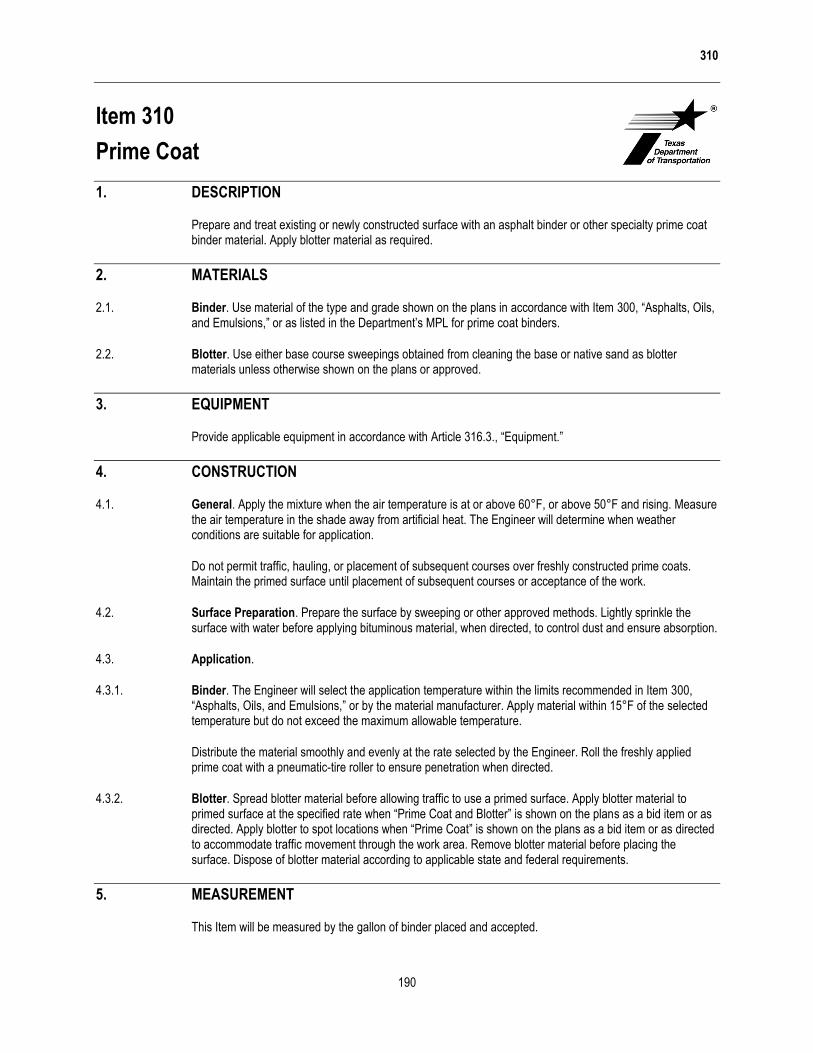
310
190
Item 310
Prime Coat
1. DESCRIPTION
Prepare and treat existing or newly constructed surface with an asphalt binder or other specialty prime coat binder material. Apply blotter material as required.
2. MATERIALS
2.1. Binder. Use material of the type and grade shown on the plans in accordance with Item 300, “Asphalts, Oils, and Emulsions,” or as listed in the Department’s MPL for prime coat binders.
2.2. Blotter. Use either base course sweepings obtained from cleaning the base or native sand as blotter materials unless otherwise shown on the plans or approved.
3. EQUIPMENT
Provide applicable equipment in accordance with Article 316.3., “Equipment.”
4. CONSTRUCTION
4.1. General. Apply the mixture when the air temperature is at or above 60°F, or above 50°F and rising. Measure the air temperature in the shade away from artificial heat. The Engineer will determine when weather conditions are suitable for application.
Do not permit traffic, hauling, or placement of subsequent courses over freshly constructed prime coats. Maintain the primed surface until placement of subsequent courses or acceptance of the work.
4.2. Surface Preparation. Prepare the surface by sweeping or other approved methods. Lightly sprinkle the surface with water before applying bituminous material, when directed, to control dust and ensure absorption.
4.3. Application.
4.3.1. Binder. The Engineer will select the application temperature within the limits recommended in Item 300, “Asphalts, Oils, and Emulsions,” or by the material manufacturer. Apply material within 15°F of the selected temperature but do not exceed the maximum allowable temperature.
Distribute the material smoothly and evenly at the rate selected by the Engineer. Roll the freshly applied prime coat with a pneumatic-tire roller to ensure penetration when directed.
4.3.2. Blotter. Spread blotter material before allowing traffic to use a primed surface. Apply blotter material to primed surface at the specified rate when “Prime Coat and Blotter” is shown on the plans as a bid item or as directed. Apply blotter to spot locations when “Prime Coat” is shown on the plans as a bid item or as directed to accommodate traffic movement through the work area. Remove blotter material before placing the surface. Dispose of blotter material according to applicable state and federal requirements.
5. MEASUREMENT
This Item will be measured by the gallon of binder placed and accepted.

310
191
6. PAYMENT
The work performed and materials furnished in accordance with this Item and measured as provided under “Measurement” will be paid for at the unit price bid for “Prime Coat” or “Prime Coat and Blotter” of the type and grade of binder specified. This price is full compensation for cleaning and sprinkling the area to be primed; materials, including blotter material; and rolling, equipment, labor, tools, and incidentals.

(THIS PAGE IS INTENTIONALLY LEFT BLANK)
340
214
Item 340
Dense-Graded Hot-Mix Asphalt (Small Quantity)
1. DESCRIPTION
Construct a hot-mix asphalt (HMA) pavement layer composed of a compacted, dense-graded mixture of aggregate and asphalt binder mixed hot in a mixing plant. This specification is intended for small quantity (SQ) HMA projects, typically under 5,000 tons total production.
2. MATERIALS
Furnish uncontaminated materials of uniform quality that meet the requirements of the plans and specifications.
Notify the Engineer of all material sources and before changing any material source or formulation. The Engineer will verify that the specification requirements are met when the Contractor makes a source or formulation change, and may require a new laboratory mixture design, trial batch, or both. The Engineer may sample and test project materials at any time during the project to verify specification compliance in accordance with Item 6, “Control of Materials.”
2.1. Aggregate. Furnish aggregates from sources that conform to the requirements shown in Table 1 and as specified in this Section. Aggregate requirements in this Section, including those shown in Table 1, may be modified or eliminated when shown on the plans. Additional aggregate requirements may be specified when shown on the plans. Provide aggregate stockpiles that meet the definitions in this Section for coarse, intermediate, or fine aggregate. Aggregate from reclaimed asphalt pavement (RAP) is not required to meet Table 1 requirements unless otherwise shown on the plans. Supply aggregates that meet the definitions in Tex-100-E for crushed gravel or crushed stone. The Engineer will designate the plant or the quarry as the sampling location. Provide samples from materials produced for the project. The Engineer will establish the Surface Aggregate Classification (SAC) and perform Los Angeles abrasion, magnesium sulfate soundness, and Micro-Deval tests. Perform all other aggregate quality tests listed in Table 1. Document all test results on the mixture design report. The Engineer may perform tests on independent or split samples to verify Contractor test results. Stockpile aggregates for each source and type separately. Determine aggregate gradations for mixture design and production testing based on the washed sieve analysis given in Tex-200-F, Part II.
2.1.1. Coarse Aggregate. Coarse aggregate stockpiles must have no more than 20% material passing the No. 8 sieve. Aggregates from sources listed in the Department’s Bituminous Rated Source Quality Catalog (BRSQC) are preapproved for use. Use only the rated values for hot-mix listed in the BRSQC. Rated values for surface treatment (ST) do not apply to coarse aggregate sources used in hot-mix asphalt.
For sources not listed on the Department’s BRSQC:
build an individual stockpile for each material;
request the Department test the stockpile for specification compliance; and
once approved, do not add material to the stockpile unless otherwise approved.
Provide aggregate from non-listed sources only when tested by the Engineer and approved before use. Allow 30 calendar days for the Engineer to sample, test, and report results for non-listed sources.
Provide coarse aggregate with at least the minimum SAC shown on the plans. SAC requirements only apply to aggregates used on the surface of travel lanes. SAC requirements apply to aggregates used on surfaces other than travel lanes when shown on the plans. The SAC for sources on the Department’s Aggregate Quality Monitoring Program (AQMP) (Tex-499-A) is listed in the BRSQC.
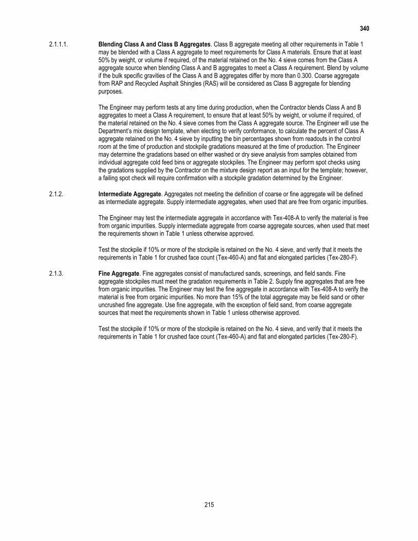
340
215
2.1.1.1. Blending Class A and Class B Aggregates. Class B aggregate meeting all other requirements in Table 1 may be blended with a Class A aggregate to meet requirements for Class A materials. Ensure that at least 50% by weight, or volume if required, of the material retained on the No. 4 sieve comes from the Class A aggregate source when blending Class A and B aggregates to meet a Class A requirement. Blend by volume if the bulk specific gravities of the Class A and B aggregates differ by more than 0.300. Coarse aggregate from RAP and Recycled Asphalt Shingles (RAS) will be considered as Class B aggregate for blending purposes.
The Engineer may perform tests at any time during production, when the Contractor blends Class A and B aggregates to meet a Class A requirement, to ensure that at least 50% by weight, or volume if required, of the material retained on the No. 4 sieve comes from the Class A aggregate source. The Engineer will use the Department’s mix design template, when electing to verify conformance, to calculate the percent of Class A aggregate retained on the No. 4 sieve by inputting the bin percentages shown from readouts in the control room at the time of production and stockpile gradations measured at the time of production. The Engineer may determine the gradations based on either washed or dry sieve analysis from samples obtained from individual aggregate cold feed bins or aggregate stockpiles. The Engineer may perform spot checks using the gradations supplied by the Contractor on the mixture design report as an input for the template; however, a failing spot check will require confirmation with a stockpile gradation determined by the Engineer.
2.1.2. Intermediate Aggregate. Aggregates not meeting the definition of coarse or fine aggregate will be defined as intermediate aggregate. Supply intermediate aggregates, when used that are free from organic impurities.
The Engineer may test the intermediate aggregate in accordance with Tex-408-A to verify the material is free from organic impurities. Supply intermediate aggregate from coarse aggregate sources, when used that meet the requirements shown in Table 1 unless otherwise approved.
Test the stockpile if 10% or more of the stockpile is retained on the No. 4 sieve, and verify that it meets the requirements in Table 1 for crushed face count (Tex-460-A) and flat and elongated particles (Tex-280-F).
2.1.3. Fine Aggregate. Fine aggregates consist of manufactured sands, screenings, and field sands. Fine aggregate stockpiles must meet the gradation requirements in Table 2. Supply fine aggregates that are free from organic impurities. The Engineer may test the fine aggregate in accordance with Tex-408-A to verify the material is free from organic impurities. No more than 15% of the total aggregate may be field sand or other uncrushed fine aggregate. Use fine aggregate, with the exception of field sand, from coarse aggregate sources that meet the requirements shown in Table 1 unless otherwise approved.
Test the stockpile if 10% or more of the stockpile is retained on the No. 4 sieve, and verify that it meets the requirements in Table 1 for crushed face count (Tex-460-A) and flat and elongated particles (Tex-280-F).
340
216
Table 1 Aggregate Quality Requirements
Property Test Method Requirement
Coarse Aggregate
SAC Tex-499-A (AQMP) As shown on the plans
Deleterious material, %, Max Tex-217-F, Part I 1.5
Decantation, %, Max Tex-217-F, Part II 1.5
Micro-Deval abrasion, % Tex-461-A Note1
Los Angeles abrasion, %, Max Tex-410-A 40
Magnesium sulfate soundness, 5 cycles, %, Max Tex-411-A 30
Crushed face count,2 %, Min Tex-460-A, Part I 85
Flat and elongated particles @ 5:1, %, Max Tex-280-F 10
Fine Aggregate
Linear shrinkage, %, Max Tex-107-E 3
Combined Aggregate3
Sand equivalent, %, Min Tex-203-F 45
1. Not used for acceptance purposes. Optional test used by the Engineer as an indicator of the need for further investigation.
2. Only applies to crushed gravel. 3. Aggregates, without mineral filler, RAP, RAS, or additives, combined as used in the job-mix formula (JMF).
Table 2 Gradation Requirements for Fine Aggregate
Sieve Size % Passing by Weight or Volume
3/8″ 100
#8 70–100
#200 0–30
2.2. Mineral Filler. Mineral filler consists of finely divided mineral matter such as agricultural lime, crusher fines, hydrated lime, or fly ash. Mineral filler is allowed unless otherwise shown on the plans. Use no more than 2% hydrated lime or fly ash unless otherwise shown on the plans. Use no more than 1% hydrated lime if a substitute binder is used unless otherwise shown on the plans or allowed. Test all mineral fillers except hydrated lime and fly ash in accordance with Tex-107-E to ensure specification compliance. The plans may require or disallow specific mineral fillers. Provide mineral filler, when used, that:
is sufficiently dry, free-flowing, and free from clumps and foreign matter as determined by the Engineer;
does not exceed 3% linear shrinkage when tested in accordance with Tex-107-E; and
meets the gradation requirements in Table 3.
Table 3 Gradation Requirements for Mineral Filler
Sieve Size % Passing by Weight or Volume
#8 100
#200 55–100
2.3. Baghouse Fines. Fines collected by the baghouse or other dust-collecting equipment may be reintroduced into the mixing drum.
2.4. Asphalt Binder. Furnish the type and grade of performance-graded (PG) asphalt specified on the plans.
2.5. Tack Coat. Furnish CSS-1H, SS-1H, or a PG binder with a minimum high-temperature grade of PG 58 for tack coat binder in accordance with Item 300, “Asphalts, Oils, and Emulsions.” Specialized or preferred tack coat materials may be allowed or required when shown on the plans. Do not dilute emulsified asphalts at the terminal, in the field, or at any other location before use.
The Engineer will obtain at least one sample of the tack coat binder per project in accordance with Tex-500-C, Part III, and test it to verify compliance with Item 300, “Asphalts, Oils, and Emulsions.” The Engineer will obtain the sample from the asphalt distributor immediately before use.
2.6. Additives. Use the type and rate of additive specified when shown on the plans. Additives that facilitate mixing, compaction, or improve the quality of the mixture are allowed when approved. Provide the Engineer
340
217
with documentation, such as the bill of lading, showing the quantity of additives used in the project unless otherwise directed.
2.6.1. Lime and Liquid Antistripping Agent. When lime or a liquid antistripping agent is used, add in accordance with Item 301, “Asphalt Antistripping Agents.” Do not add lime directly into the mixing drum of any plant where lime is removed through the exhaust stream unless the plant has a baghouse or dust collection system that reintroduces the lime into the drum.
2.6.2. Warm Mix Asphalt (WMA). Warm Mix Asphalt (WMA) is defined as HMA that is produced within a target temperature discharge range of 215°F and 275°F using approved WMA additives or processes from the Department’s MPL.
WMA is allowed for use on all projects and is required when shown on the plans. When WMA is required, the maximum placement or target discharge temperature for WMA will be set at a value below 275°F.
Department-approved WMA additives or processes may be used to facilitate mixing and compaction of HMA produced at target discharge temperatures above 275°F; however, such mixtures will not be defined as WMA.
2.7. Recycled Materials. Use of RAP and RAS is permitted unless otherwise shown on the plans. Do not exceed the maximum allowable percentages of RAP and RAS shown in Table 4. The allowable percentages shown in Table 4 may be decreased or increased when shown on the plans. Determine asphalt binder content and gradation of the RAP and RAS stockpiles for mixture design purposes in accordance with Tex-236-F. The Engineer may verify the asphalt binder content of the stockpiles at any time during production. Perform other tests on RAP and RAS when shown on the plans. Asphalt binder from RAP and RAS is designated as recycled asphalt binder. Calculate and ensure that the ratio of the recycled asphalt binder to total binder does not exceed the percentages shown in Table 5 during mixture design and HMA production when RAP or RAS is used. Use a separate cold feed bin for each stockpile of RAP and RAS during HMA production.
Surface, intermediate, and base mixes referenced in Tables 4 and 5 are defined as follows:
Surface. The final HMA lift placed at or near the top of the pavement structure;
Intermediate. Mixtures placed below an HMA surface mix and less than or equal to 8.0 in. from the
riding surface; and
Base. Mixtures placed greater than 8.0 in. from the riding surface.
2.7.1. RAP. RAP is salvaged, milled, pulverized, broken, or crushed asphalt pavement. Crush or break RAP so that 100% of the particles pass the 2 in. sieve. Fractionated RAP is defined as 2 or more RAP stockpiles, divided into coarse and fine fractions.
Use of Contractor-owned RAP, including HMA plant waste, is permitted unless otherwise shown on the plans. Department-owned RAP stockpiles are available for the Contractor’s use when the stockpile locations are shown on the plans. If Department-owned RAP is available for the Contractor’s use, the Contractor may use Contractor-owned fractionated RAP and replace it with an equal quantity of Department-owned RAP. This allowance does not apply to a Contractor using unfractionated RAP. Department-owned RAP generated through required work on the Contract is available for the Contractor’s use when shown on the plans. Perform any necessary tests to ensure Contractor- or Department-owned RAP is appropriate for use. The Department will not perform any tests or assume any liability for the quality of the Department-owned RAP unless otherwise shown on the plans. The Contractor will retain ownership of RAP generated on the project when shown on the plans.
The coarse RAP stockpile will contain only material retained by processing over a 3/8-in. or 1/2-in. screen unless otherwise approved. The fine RAP stockpile will contain only material passing the 3/8-in. or 1/2-in. screen unless otherwise approved. The Engineer may allow the Contractor to use an alternate to the 3/8-in. or 1/2-in. screen to fractionate the RAP. The maximum percentages of fractionated RAP may be comprised of coarse or fine fractionated RAP or the combination of both coarse and fine fractionated RAP.
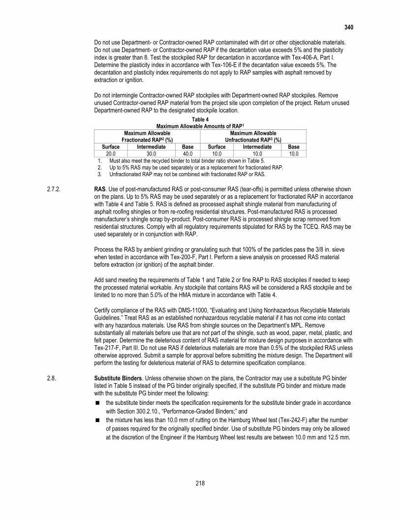
340
218
Do not use Department- or Contractor-owned RAP contaminated with dirt or other objectionable materials. Do not use Department- or Contractor-owned RAP if the decantation value exceeds 5% and the plasticity index is greater than 8. Test the stockpiled RAP for decantation in accordance with Tex-406-A, Part I. Determine the plasticity index in accordance with Tex-106-E if the decantation value exceeds 5%. The decantation and plasticity index requirements do not apply to RAP samples with asphalt removed by extraction or ignition.
Do not intermingle Contractor-owned RAP stockpiles with Department-owned RAP stockpiles. Remove unused Contractor-owned RAP material from the project site upon completion of the project. Return unused Department-owned RAP to the designated stockpile location.
Table 4 Maximum Allowable Amounts of RAP1
Maximum Allowable Fractionated RAP2 (%)
Maximum Allowable Unfractionated RAP3 (%)
Surface Intermediate Base Surface Intermediate Base
20.0 30.0 40.0 10.0 10.0 10.0
1. Must also meet the recycled binder to total binder ratio shown in Table 5. 2. Up to 5% RAS may be used separately or as a replacement for fractionated RAP. 3. Unfractionated RAP may not be combined with fractionated RAP or RAS.
2.7.2. RAS. Use of post-manufactured RAS or post-consumer RAS (tear-offs) is permitted unless otherwise shown on the plans. Up to 5% RAS may be used separately or as a replacement for fractionated RAP in accordance with Table 4 and Table 5. RAS is defined as processed asphalt shingle material from manufacturing of asphalt roofing shingles or from re-roofing residential structures. Post-manufactured RAS is processed manufacturer’s shingle scrap by-product. Post-consumer RAS is processed shingle scrap removed from residential structures. Comply with all regulatory requirements stipulated for RAS by the TCEQ. RAS may be used separately or in conjunction with RAP.
Process the RAS by ambient grinding or granulating such that 100% of the particles pass the 3/8 in. sieve when tested in accordance with Tex-200-F, Part I. Perform a sieve analysis on processed RAS material before extraction (or ignition) of the asphalt binder.
Add sand meeting the requirements of Table 1 and Table 2 or fine RAP to RAS stockpiles if needed to keep the processed material workable. Any stockpile that contains RAS will be considered a RAS stockpile and be limited to no more than 5.0% of the HMA mixture in accordance with Table 4.
Certify compliance of the RAS with DMS-11000, “Evaluating and Using Nonhazardous Recyclable Materials Guidelines.” Treat RAS as an established nonhazardous recyclable material if it has not come into contact with any hazardous materials. Use RAS from shingle sources on the Department’s MPL. Remove substantially all materials before use that are not part of the shingle, such as wood, paper, metal, plastic, and felt paper. Determine the deleterious content of RAS material for mixture design purposes in accordance with Tex-217-F, Part III. Do not use RAS if deleterious materials are more than 0.5% of the stockpiled RAS unless otherwise approved. Submit a sample for approval before submitting the mixture design. The Department will perform the testing for deleterious material of RAS to determine specification compliance.
2.8. Substitute Binders. Unless otherwise shown on the plans, the Contractor may use a substitute PG binder listed in Table 5 instead of the PG binder originally specified, if the substitute PG binder and mixture made with the substitute PG binder meet the following:
the substitute binder meets the specification requirements for the substitute binder grade in accordance
with Section 300.2.10., “Performance-Graded Binders;” and
the mixture has less than 10.0 mm of rutting on the Hamburg Wheel test (Tex-242-F) after the number
of passes required for the originally specified binder. Use of substitute PG binders may only be allowed
at the discretion of the Engineer if the Hamburg Wheel test results are between 10.0 mm and 12.5 mm.
340
219
Table 5 Allowable Substitute PG Binders and Maximum Recycled Binder Ratios
Originally Specified PG Binder
Allowable Substitute PG
Binder
Maximum Ratio of Recycled Binder1 to Total Binder (%)
Surface Intermediate Base
HMA
76-222 70-22 or 64-22 20.0 20.0 20.0
70-28 or 64-28 30.0 35.0 40.0
70-222 64-22 20.0 20.0 20.0
64-28 or 58-28 30.0 35.0 40.0
64-222 58-28 30.0 35.0 40.0
76-282 70-28 or 64-28 20.0 20.0 20.0
64-34 30.0 35.0 40.0
70-282 64-28 or 58-28 20.0 20.0 20.0
64-34 or 58-34 30.0 35.0 40.0
64-282 58-28 20.0 20.0 20.0
58-34 30.0 35.0 40.0
WMA3
76-222 70-22 or 64-22 30.0 35.0 40.0
70-222 64-22 or 58-28 30.0 35.0 40.0
64-224 58-28 30.0 35.0 40.0
76-282 70-28 or 64-28 30.0 35.0 40.0
70-282 64-28 or 58-28 30.0 35.0 40.0
64-284 58-28 30.0 35.0 40.0
1. Combined recycled binder from RAP and RAS. 2. Use no more than 20.0% recycled binder when using this originally specified PG binder. 3. WMA as defined in Section 340.2.6.2., “Warm Mix Asphalt (WMA).” 4. When used with WMA, this originally specified PG binder is allowed for use at the
maximum recycled binder ratios shown in this table.
3. EQUIPMENT
Provide required or necessary equipment in accordance with Item 320, “Equipment for Asphalt Concrete Pavement.”
4. CONSTRUCTION
Produce, haul, place, and compact the specified paving mixture. In addition to tests required by the specification, Contractors may perform other QC tests as deemed necessary. At any time during the project, the Engineer may perform production and placement tests as deemed necessary in accordance with Item 5, “Control of the Work.” Schedule and participate in a pre-paving meeting with the Engineer on or before the first day of paving unless otherwise directed.
4.1. Certification. Personnel certified by the Department-approved hot-mix asphalt certification program must conduct all mixture designs, sampling, and testing in accordance with Table 6. Supply the Engineer with a list of certified personnel and copies of their current certificates before beginning production and when personnel changes are made. Provide a mixture design developed and signed by a Level 2 certified specialist.
340
220
Table 6 Test Methods, Test Responsibility, and Minimum Certification Levels
Test Description Test Method Contractor Engineer Level1
1. Aggregate and Recycled Material Testing
Sampling Tex-221-F 1A
Dry sieve Tex-200-F, Part I 1A
Washed sieve Tex-200-F, Part II 1A
Deleterious material Tex-217-F, Parts I & III 1A
Decantation Tex-217-F, Part II 1A
Los Angeles abrasion Tex-410-A TxDOT
Magnesium sulfate soundness Tex-411-A TxDOT
Micro-Deval abrasion Tex-461-A 2
Crushed face count Tex-460-A 2
Flat and elongated particles Tex-280-F 2
Linear shrinkage Tex-107-E 2
Sand equivalent Tex-203-F 2
Organic impurities Tex-408-A 2
2. Asphalt Binder & Tack Coat Sampling
Asphalt binder sampling Tex-500-C, Part II 1A/1B
Tack coat sampling Tex-500-C, Part III 1A/1B
3. Mix Design & Verification
Design and JMF changes Tex-204-F 2
Mixing Tex-205-F 2
Molding (TGC) Tex-206-F 1A
Molding (SGC) Tex-241-F 1A
Laboratory-molded density Tex-207-F 1A
VMA2 (calculation only) Tex-204-F 2
Rice gravity Tex-227-F 1A
Ignition oven correction factors3 Tex-236-F 2
Indirect tensile strength Tex-226-F 2
Hamburg Wheel test Tex-242-F 2
Boil test Tex-530-C 1A
4. Production Testing
Mixture sampling Tex-222-F 1A
Molding (TGC) Tex-206-F 1A
Molding (SGC) Tex-241-F 1A
Laboratory-molded density Tex-207-F 1A
VMA2 (calculation only) Tex-204-F 1A
Rice gravity Tex-227-F 1A
Gradation & asphalt binder content3 Tex-236-F 1A
Moisture content Tex-212-F 1A
Hamburg Wheel test Tex-242-F 2
Boil test Tex-530-C 1A
5. Placement Testing
Trimming roadway cores Tex-207-F 1A/1B
In-place air voids Tex-207-F 1A/1B
Establish rolling pattern Tex-207-F 1B
Ride quality measurement Tex-1001-S Note4
1. Level 1A, 1B, and 2 are certification levels provided by the Hot Mix Asphalt Center certification program. 2. Voids in mineral aggregates. 3. Refer to Section 340.4.8.3., “Production Testing,” for exceptions to using an ignition oven. 4. Profiler and operator are required to be certified at the Texas A&M Transportation Institute facility when Surface
Test Type B is specified.
4.2. Reporting, Testing, and Responsibilities. Use Department-provided templates to record and calculate all test data pertaining to the mixture design. The Engineer will use Department templates for any production and placement testing. Obtain the current version of the templates at http://www.txdot.gov/inside-txdot/forms-publications/consultants-contractors/forms/site-manager.html or from the Engineer.
340
221
The maximum allowable time for the Engineer to exchange test data with the Contractor is as given in Table 7 unless otherwise approved. The Engineer will immediately report to the Contractor any test result that requires suspension of production or placement or that fails to meet the specification requirements.
Subsequent mix placed after test results are available to the Contractor, which require suspension of operations, may be considered unauthorized work. Unauthorized work will be accepted or rejected at the discretion of the Engineer in accordance with Article 5.3., “Conformity with Plans, Specifications, and Special Provisions.”
Table 7 Reporting Schedule
Description Reported By Reported To To Be Reported Within
Production Testing
Gradation
Engineer Contractor 1 working day of
completion of the test
Asphalt binder content
Laboratory-molded density
VMA (calculation)
Hamburg Wheel test
Moisture content
Boil test
Binder tests
Placement Testing
In-place air voids Engineer Contractor 1 working day of
completion of the test1
1. 2 days are allowed if cores cannot be dried to constant weight within 1 day.
4.3. Mixture Design.
4.3.1. Design Requirements. The Contractor may design the mixture using a Texas Gyratory Compactor (TGC) or a Superpave Gyratory Compactor (SGC) unless otherwise shown on the plans. Use the dense-graded design procedure provided in Tex-204-F. Design the mixture to meet the requirements listed in Tables 1, 2, 3, 4, 5, 8, 9, and 10.
4.3.1.1. Target Laboratory-Molded Density When The TGC Is Used. Design the mixture at a 96.5% target laboratory-molded density. Increase the target laboratory-molded density to 97.0% or 97.5% at the Contractor’s discretion or when shown on the plans or specification.
4.3.1.2. Design Number of Gyrations (Ndesign) When The SGC Is Used. Design the mixture at 50 gyrations (Ndesign). Use a target laboratory-molded density of 96.0% to design the mixture; however, adjustments can be made to the Ndesign value as noted in Table 9. The Ndesign level may be reduced to no less than 35 gyrations at the Contractor’s discretion.
Use an approved laboratory from the Department’s MPL to perform the Hamburg Wheel test in accordance with Tex-242-F, and provide results with the mixture design, or provide the laboratory mixture and request that the Department perform the Hamburg Wheel test. The Engineer will be allowed 10 working days to provide the Contractor with Hamburg Wheel test results on the laboratory mixture design.
The Engineer will provide the mixture design when shown on the plans. The Contractor may submit a new mixture design at any time during the project. The Engineer will verify and approve all mixture designs (JMF1) before the Contractor can begin production.
Provide the Engineer with a mixture design report using the Department-provided template. Include the following items in the report:
the combined aggregate gradation, source, specific gravity, and percent of each material used;
asphalt binder content and aggregate gradation of RAP and RAS stockpiles;
the target laboratory-molded density (or Ndesign level when using the SGC);
results of all applicable tests;

340
222
the mixing and molding temperatures;
the signature of the Level 2 person or persons that performed the design;
the date the mixture design was performed; and
a unique identification number for the mixture design.
Table 8 Master Gradation Limits (% Passing by Weight or Volume) and VMA Requirements
Sieve Size
A Coarse Base
B Fine Base
C Coarse Surface
D Fine
Surface
F Fine
Mixture
2″ 100.01 – – – –
1-1/2″ 98.0–100.0 100.01 – – –
1″ 78.0–94.0 98.0–100.0 100.01 – –
3/4″ 64.0–85.0 84.0–98.0 95.0–100.0 100.01 –
1/2″ 50.0–70.0 – – 98.0–100.0 100.01
3/8″ – 60.0–80.0 70.0–85.0 85.0–100.0 98.0–100.0
#4 30.0–50.0 40.0–60.0 43.0–63.0 50.0–70.0 70.0–90.0
#8 22.0–36.0 29.0–43.0 32.0–44.0 35.0–46.0 38.0–48.0
#30 8.0–23.0 13.0–28.0 14.0–28.0 15.0–29.0 12.0–27.0
#50 3.0–19.0 6.0–20.0 7.0–21.0 7.0–20.0 6.0–19.0
#200 2.0–7.0 2.0–7.0 2.0–7.0 2.0–7.0 2.0–7.0
Design VMA, % Minimum
– 12.0 13.0 14.0 15.0 16.0
Production (Plant-Produced) VMA, % Minimum
– 11.5 12.5 13.5 14.5 15.5
1. Defined as maximum sieve size. No tolerance allowed.
Table 9 Laboratory Mixture Design Properties
Mixture Property Test Method Requirement
Target laboratory-molded density, % (TGC) Tex-207-F 96.51
Design gyrations (Ndesign for SGC) Tex-241-F 502
Indirect tensile strength (dry), psi Tex-226-F 85–2003
Boil test4 Tex-530-C –
1. Increase to 97.0% or 97.5% at the Contractor’s discretion or when shown on the plans or specification.
2. Adjust within a range of 35–100 gyrations when shown on the plans or specification or when mutually agreed between the Engineer and Contractor.
3. The Engineer may allow the IDT strength to exceed 200 psi if the corresponding Hamburg Wheel rut depth is greater than 3.0 mm and less than 12.5 mm.
4. Used to establish baseline for comparison to production results. May be waived when approved.
Table 10
Hamburg Wheel Test Requirements
High-Temperature Binder Grade Test Method Minimum # of Passes
@ 12.5 mm1 Rut Depth, Tested @ 50°C
PG 64 or lower
Tex-242-F
10,0002
PG 70 15,0003
PG 76 or higher 20,000
1. When the rut depth at the required minimum number of passes is less than 3 mm, the Engineer may require the Contractor to increase the target laboratory-molded density (TGC) by 0.5% to no more than 97.5% or lower the Ndesign level (SGC) to no less than 35 gyrations.
2. May be decreased to no less than 5,000 passes when shown on the plans. 3. May be decreased to no less than 10,000 passes when shown on the plans.
4.3.2. Job-Mix Formula Approval. The job-mix formula (JMF) is the combined aggregate gradation, target laboratory-molded density (or Ndesign level), and target asphalt percentage used to establish target values for hot-mix production. JMF1 is the original laboratory mixture design used to produce the trial batch. When
340
223
WMA is used, JMF1 may be designed and submitted to the Engineer without including the WMA additive. When WMA is used, document the additive or process used and recommended rate on the JMF1 submittal. Furnish a mix design report (JMF1) with representative samples of all component materials and request approval to produce the trial batch. Provide approximately 10,000 g of the design mixture and request that the Department perform the Hamburg Wheel test if opting to have the Department perform the test. The Engineer will verify JMF1 based on plant-produced mixture from the trial batch unless otherwise determined. The Engineer may accept an existing mixture design previously used on a Department project and may waive the trial batch to verify JMF1. Provide split samples of the mixtures and blank samples used to determine the ignition oven correction factors. The Engineer will determine the aggregate and asphalt correction factors from the ignition oven used for production testing in accordance with Tex-236-F.
The Engineer will use a TGC calibrated in accordance with Tex-914-K in molding production samples. Provide an SGC at the Engineer’s field laboratory for use in molding production samples if the SGC is used to design the mix.
The Engineer may perform Tex-530-C and retain the tested sample for comparison purposes during production. The Engineer may waive the requirement for the boil test.
4.3.3. JMF Adjustments. If JMF adjustments are necessary to achieve the specified requirements, the adjusted JMF must:
be provided to the Engineer in writing before the start of a new lot;
be numbered in sequence to the previous JMF;
meet the mixture requirements in Table 4 and Table 5;
meet the master gradation limits shown in Table 8; and
be within the operational tolerances of the current JMF listed in Table 11.
The Engineer may adjust the asphalt binder content to maintain desirable laboratory density near the optimum value while achieving other mix requirements.
Table 11 Operational Tolerances
Description Test Method Allowable Difference Between Trial Batch and JMF1 Target
Allowable Difference from Current JMF Target
Individual % retained for #8 sieve and larger Tex-200-F
or Tex-236-F
Must be within master grading limits
in Table 8
±5.01,2
Individual % retained for sieves smaller than #8 and larger than #200
±3.01,2
% passing the #200 sieve ±2.01,2
Asphalt binder content, % Tex-236-F ±0.5 ±0.32
Laboratory-molded density, % Tex-207-F ±1.0 ±1.0
VMA, %, min Tex-204-F Note3 Note3
1. When within these tolerances, mixture production gradations may fall outside the master grading limits; however, the % passing the #200 will be considered out of tolerance when outside the master grading limits.
2. Only applies to mixture produced for Lot 1 and higher. 3. Mixture is required to meet Table 8 requirements.
4.4. Production Operations. Perform a new trial batch when the plant or plant location is changed. Take corrective action and receive approval to proceed after any production suspension for noncompliance to the specification. Submit a new mix design and perform a new trial batch when the asphalt binder content of:
any RAP stockpile used in the mix is more than 0.5% higher than the value shown on the mixture design
report; or
RAS stockpile used in the mix is more than 2.0% higher than the value shown on the mixture design
report.
4.4.1. Storage and Heating of Materials. Do not heat the asphalt binder above the temperatures specified in Item 300, “Asphalts, Oils, and Emulsions,” or outside the manufacturer’s recommended values. Provide the Engineer with daily records of asphalt binder and hot-mix asphalt discharge temperatures (in legible and
340
224
discernible increments) in accordance with Item 320, “Equipment for Asphalt Concrete Pavement,” unless otherwise directed. Do not store mixture for a period long enough to affect the quality of the mixture, nor in any case longer than 12 hr. unless otherwise approved.
4.4.2. Mixing and Discharge of Materials. Notify the Engineer of the target discharge temperature and produce the mixture within 25°F of the target. Monitor the temperature of the material in the truck before shipping to ensure that it does not exceed 350°F (or 275°F for WMA) and is not lower than 215°F. The Department will not pay for or allow placement of any mixture produced above 350°F.
Produce WMA within the target discharge temperature range of 215°F and 275°F when WMA is required. Take corrective action any time the discharge temperature of the WMA exceeds the target discharge range. The Engineer may suspend production operations if the Contractor’s corrective action is not successful at controlling the production temperature within the target discharge range. Note that when WMA is produced, it may be necessary to adjust burners to ensure complete combustion such that no burner fuel residue remains in the mixture.
Control the mixing time and temperature so that substantially all moisture is removed from the mixture before discharging from the plant. The Engineer may determine the moisture content by oven-drying in accordance with Tex-212-F, Part II, and verify that the mixture contains no more than 0.2% of moisture by weight. The Engineer will obtain the sample immediately after discharging the mixture into the truck, and will perform the test promptly.
4.5. Hauling Operations. Clean all truck beds before use to ensure that mixture is not contaminated. Use a release agent shown on the Department’s MPL to coat the inside bed of the truck when necessary.
Use equipment for hauling as defined in Section 340.4.6.3.2., “Hauling Equipment.” Use other hauling equipment only when allowed.
4.6. Placement Operations. Collect haul tickets from each load of mixture delivered to the project and provide the Department’s copy to the Engineer approximately every hour, or as directed. Use a hand-held thermal camera or infrared thermometer to measure and record the internal temperature of the mixture as discharged from the truck or Material Transfer Device (MTD) before or as the mix enters the paver and an approximate station number or GPS coordinates on each ticket unless otherwise directed. Calculate the daily yield and cumulative yield for the specified lift and provide to the Engineer at the end of paving operations for each day unless otherwise directed. The Engineer may suspend production if the Contractor fails to produce and provide haul tickets and yield calculations by the end of paving operations for each day.
Prepare the surface by removing raised pavement markers and objectionable material such as moisture, dirt, sand, leaves, and other loose impediments from the surface before placing mixture. Remove vegetation from pavement edges. Place the mixture to meet the typical section requirements and produce a smooth, finished surface with a uniform appearance and texture. Offset longitudinal joints of successive courses of hot-mix by at least 6 in. Place mixture so that longitudinal joints on the surface course coincide with lane lines, or as directed. Ensure that all finished surfaces will drain properly.
Place the mixture at the rate or thickness shown on the plans. The Engineer will use the guidelines in Table 12 to determine the compacted lift thickness of each layer when multiple lifts are required. The thickness determined is based on the rate of 110 lb./sq. yd. for each inch of pavement unless otherwise shown on the plans.

340
225
Table 12 Compacted Lift Thickness and Required Core Height
Mixture Type Compacted Lift Thickness Guidelines Minimum Untrimmed Core
Height (in.) Eligible for Testing Minimum (in.) Maximum (in.)
A 3.00 6.00 2.00
B 2.50 5.00 1.75
C 2.00 4.00 1.50
D 1.50 3.00 1.25
F 1.25 2.50 1.25
4.6.1. Weather Conditions. Place mixture when the roadway surface temperature is at or above 60°F unless otherwise approved. Measure the roadway surface temperature with a hand-held thermal camera or infrared thermometer. The Engineer may allow mixture placement to begin before the roadway surface reaches the required temperature if conditions are such that the roadway surface will reach the required temperature within 2 hr. of beginning placement operations. Place mixtures only when weather conditions and moisture conditions of the roadway surface are suitable as determined by the Engineer. The Engineer may restrict the Contractor from paving if the ambient temperature is likely to drop below 32°F within 12 hr. of paving.
4.6.2. Tack Coat. Clean the surface before placing the tack coat. The Engineer will set the rate between 0.04 and 0.10 gal. of residual asphalt per square yard of surface area. Apply a uniform tack coat at the specified rate unless otherwise directed. Apply the tack coat in a uniform manner to avoid streaks and other irregular patterns. Apply a thin, uniform tack coat to all contact surfaces of curbs, structures, and all joints. Allow adequate time for emulsion to break completely before placing any material. Prevent splattering of tack coat when placed adjacent to curb, gutter, and structures. Roll the tack coat with a pneumatic-tire roller to remove streaks and other irregular patterns when directed.
4.6.3. Lay-Down Operations.
4.6.3.1. Windrow Operations. Operate windrow pickup equipment so that when hot-mix is placed in windrows substantially all the mixture deposited on the roadbed is picked up and loaded into the paver.
4.6.3.2. Hauling Equipment. Use belly dumps, live bottom, or end dump trucks to haul and transfer mixture; however, with exception of paving miscellaneous areas, end dump trucks are only allowed when used in conjunction with an MTD with remixing capability unless otherwise allowed.
4.6.3.3. Screed Heaters. Turn off screed heaters, to prevent overheating of the mat, if the paver stops for more than 5 min.
4.7. Compaction. Compact the pavement uniformly to contain between 3.8% and 8.5% in-place air voids.
Furnish the type, size, and number of rollers required for compaction as approved. Use a pneumatic-tire roller to seal the surface unless excessive pickup of fines occurs. Use additional rollers as required to remove any roller marks. Use only water or an approved release agent on rollers, tamps, and other compaction equipment unless otherwise directed.
Use the control strip method shown in Tex-207-F, Part IV, on the first day of production to establish the rolling pattern that will produce the desired in-place air voids unless otherwise directed.
Use tamps to thoroughly compact the edges of the pavement along curbs, headers, and similar structures and in locations that will not allow thorough compaction with rollers. The Engineer may require rolling with a trench roller on widened areas, in trenches, and in other limited areas.
Complete all compaction operations before the pavement temperature drops below 160°F unless otherwise allowed. The Engineer may allow compaction with a light finish roller operated in static mode for pavement temperatures below 160°F.
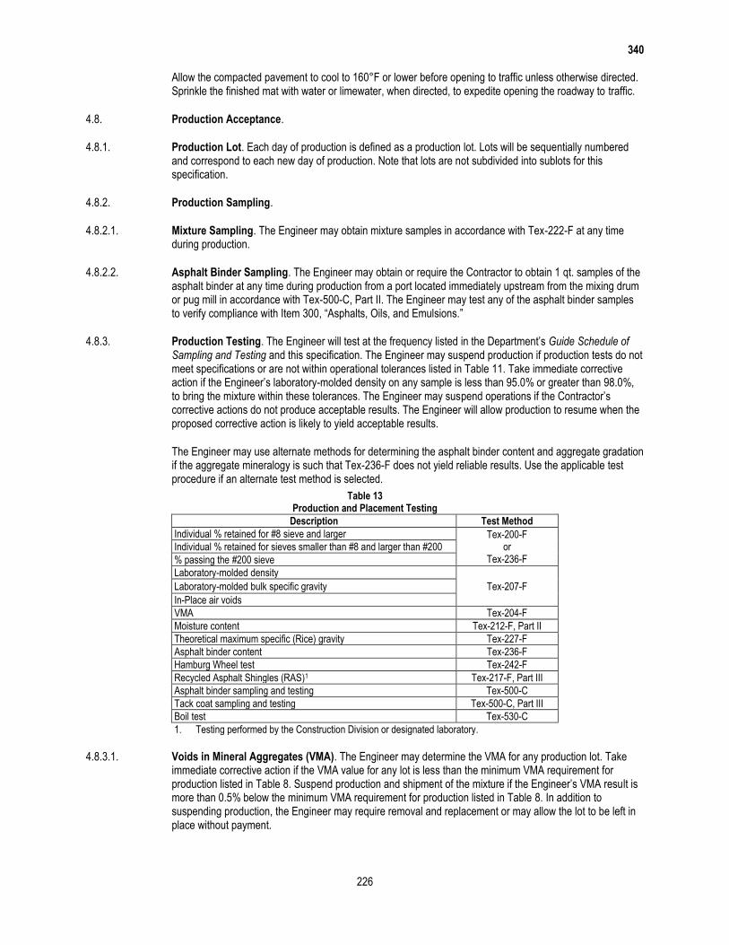
340
226
Allow the compacted pavement to cool to 160°F or lower before opening to traffic unless otherwise directed. Sprinkle the finished mat with water or limewater, when directed, to expedite opening the roadway to traffic.
4.8. Production Acceptance.
4.8.1. Production Lot. Each day of production is defined as a production lot. Lots will be sequentially numbered and correspond to each new day of production. Note that lots are not subdivided into sublots for this specification.
4.8.2. Production Sampling.
4.8.2.1. Mixture Sampling. The Engineer may obtain mixture samples in accordance with Tex-222-F at any time during production.
4.8.2.2. Asphalt Binder Sampling. The Engineer may obtain or require the Contractor to obtain 1 qt. samples of the asphalt binder at any time during production from a port located immediately upstream from the mixing drum or pug mill in accordance with Tex-500-C, Part II. The Engineer may test any of the asphalt binder samples to verify compliance with Item 300, “Asphalts, Oils, and Emulsions.”
4.8.3. Production Testing. The Engineer will test at the frequency listed in the Department’s Guide Schedule of Sampling and Testing and this specification. The Engineer may suspend production if production tests do not meet specifications or are not within operational tolerances listed in Table 11. Take immediate corrective action if the Engineer’s laboratory-molded density on any sample is less than 95.0% or greater than 98.0%, to bring the mixture within these tolerances. The Engineer may suspend operations if the Contractor’s corrective actions do not produce acceptable results. The Engineer will allow production to resume when the proposed corrective action is likely to yield acceptable results.
The Engineer may use alternate methods for determining the asphalt binder content and aggregate gradation if the aggregate mineralogy is such that Tex-236-F does not yield reliable results. Use the applicable test procedure if an alternate test method is selected.
Table 13 Production and Placement Testing
Description Test Method
Individual % retained for #8 sieve and larger Tex-200-F or
Tex-236-F Individual % retained for sieves smaller than #8 and larger than #200
% passing the #200 sieve
Laboratory-molded density
Tex-207-F Laboratory-molded bulk specific gravity
In-Place air voids
VMA Tex-204-F
Moisture content Tex-212-F, Part II
Theoretical maximum specific (Rice) gravity Tex-227-F
Asphalt binder content Tex-236-F
Hamburg Wheel test Tex-242-F
Recycled Asphalt Shingles (RAS)1 Tex-217-F, Part III
Asphalt binder sampling and testing Tex-500-C
Tack coat sampling and testing Tex-500-C, Part III
Boil test Tex-530-C
1. Testing performed by the Construction Division or designated laboratory.
4.8.3.1. Voids in Mineral Aggregates (VMA). The Engineer may determine the VMA for any production lot. Take immediate corrective action if the VMA value for any lot is less than the minimum VMA requirement for production listed in Table 8. Suspend production and shipment of the mixture if the Engineer’s VMA result is more than 0.5% below the minimum VMA requirement for production listed in Table 8. In addition to suspending production, the Engineer may require removal and replacement or may allow the lot to be left in place without payment.
340
227
4.8.3.2. Hamburg Wheel Test. The Engineer may perform a Hamburg Wheel test at any time during production, including when the boil test indicates a change in quality from the materials submitted for JMF1. In addition to testing production samples, the Engineer may obtain cores and perform Hamburg Wheel tests on any areas of the roadway where rutting is observed. Suspend production until further Hamburg Wheel tests meet the specified values when the production or core samples fail the Hamburg Wheel test criteria in Table 10. Core samples, if taken, will be obtained from the center of the finished mat or other areas excluding the vehicle wheel paths. The Engineer may require up to the entire lot of any mixture failing the Hamburg Wheel test to be removed and replaced at the Contractor’s expense.
If the Department’s or Department-approved laboratory’s Hamburg Wheel test results in a “remove and replace” condition, the Contractor may request that the Department confirm the results by re-testing the failing material. The Construction Division will perform the Hamburg Wheel tests and determine the final disposition of the material in question based on the Department’s test results.
4.8.4. Individual Loads of Hot-Mix. The Engineer can reject individual truckloads of hot-mix. When a load of hot-mix is rejected for reasons other than temperature, contamination, or excessive uncoated particles, the Contractor may request that the rejected load be tested. Make this request within 4 hr. of rejection. The Engineer will sample and test the mixture. If test results are within the operational tolerances shown in Table 11, payment will be made for the load. If test results are not within operational tolerances, no payment will be made for the load.
4.9. Placement Acceptance.
4.9.1. Placement Lot. A placement lot is defined as the area placed during a production lot (one day’s production). Placement lot numbers will correspond with production lot numbers.
4.9.2. Miscellaneous Areas. Miscellaneous areas include areas that typically involve significant handwork or discontinuous paving operations, such as temporary detours, driveways, mailbox turnouts, crossovers, gores, spot level-up areas, and other similar areas. Miscellaneous areas also include level-ups and thin overlays when the layer thickness specified on the plans is less than the minimum untrimmed core height eligible for testing shown in Table 12. The specified layer thickness is based on the rate of 110 lb./sq. yd. for each inch of pavement unless another rate is shown on the plans. Compact miscellaneous areas in accordance with Section 340.4.7., “Compaction.” Miscellaneous areas are not subject to in-place air void determination except for temporary detours when shown on the plans.
4.9.3. Placement Sampling. Provide the equipment and means to obtain and trim roadway cores on site. On site is defined as in close proximity to where the cores are taken. Obtain the cores within one working day of the time the placement lot is completed unless otherwise approved. Obtain two 6-in. diameter cores side-by-side at each location selected by the Engineer for in-place air void determination unless otherwise shown on the plans. For Type D and Type F mixtures, 4-in. diameter cores are allowed. Mark the cores for identification, measure and record the untrimmed core height, and provide the information to the Engineer. The Engineer will witness the coring operation and measurement of the core thickness.
Visually inspect each core and verify that the current paving layer is bonded to the underlying layer. Take corrective action if an adequate bond does not exist between the current and underlying layer to ensure that an adequate bond will be achieved during subsequent placement operations.
Trim the cores immediately after obtaining the cores from the roadway in accordance with Tex-207-F if the core heights meet the minimum untrimmed value listed in Table 12. Trim the cores on site in the presence of the Engineer. Use a permanent marker or paint pen to record the date and lot number on each core as well as the designation as Core A or B. The Engineer may require additional information to be marked on the core and may choose to sign or initial the core. The Engineer will take custody of the cores immediately after they are trimmed and will retain custody of the cores until the Department’s testing is completed. Before turning the trimmed cores over to the Engineer, the Contractor may wrap the trimmed cores or secure them in a manner that will reduce the risk of possible damage occurring during transport by the Engineer. After testing, the Engineer will return the cores to the Contractor.

340
228
The Engineer may have the cores transported back to the Department’s laboratory at the HMA plant via the Contractor’s haul truck or other designated vehicle. In such cases where the cores will be out of the Engineer’s possession during transport, the Engineer will use Department-provided security bags and the Roadway Core Custody protocol located at http://www.txdot.gov/business/specifications.htm to provide a secure means and process that protects the integrity of the cores during transport.
Instead of the Contractor trimming the cores on site immediately after coring, the Engineer and the Contractor may mutually agree to have the trimming operations performed at an alternate location such as a field laboratory or other similar location. In such cases, the Engineer will take possession of the cores immediately after they are obtained from the roadway and will retain custody of the cores until testing is completed. Either the Department or Contractor representative may perform trimming of the cores. The Engineer will witness all trimming operations in cases where the Contractor representative performs the trimming operation.
Dry the core holes and tack the sides and bottom immediately after obtaining the cores. Fill the hole with the same type of mixture and properly compact the mixture. Repair core holes with other methods when approved.
4.9.4. Placement Testing. The Engineer may measure in-place air voids at any time during the project to verify specification compliance.
4.9.4.1. In-Place Air Voids. The Engineer will measure in-place air voids in accordance with Tex-207-F and Tex-227-F. Cores not meeting the height requirements in Table 12 will not be tested. Before drying to a constant weight, cores may be pre-dried using a Corelok or similar vacuum device to remove excess moisture. The Engineer will use the corresponding theoretical maximum specific gravity to determine the air void content of each core. The Engineer will use the average air void content of the 2 cores to determine the in-place air voids at the selected location.
The Engineer will use the vacuum method to seal the core if required by Tex-207-F. The Engineer will use the test results from the unsealed core if the sealed core yields a higher specific gravity than the unsealed core. After determining the in-place air void content, the Engineer will return the cores and provide test results to the Contractor.
Take immediate corrective action when the in-place air voids exceed the range of 3.8% and 8.5% to bring the operation within these tolerances. The Engineer may suspend operations or require removal and replacement if the in-place air voids are less than 2.7% or greater than 9.9%. The Engineer will allow paving to resume when the proposed corrective action is likely to yield between 3.8% and 8.5% in-place air voids. Areas defined in Section 340.9.2., “Miscellaneous Areas,” are not subject to in-place air void determination.
4.9.5. Irregularities. Identify and correct irregularities including segregation, rutting, raveling, flushing, fat spots, mat slippage, irregular color, irregular texture, roller marks, tears, gouges, streaks, uncoated aggregate particles, or broken aggregate particles. The Engineer may also identify irregularities, and in such cases, the Engineer will promptly notify the Contractor. If the Engineer determines that the irregularity will adversely affect pavement performance, the Engineer may require the Contractor to remove and replace (at the Contractor’s expense) areas of the pavement that contain irregularities and areas where the mixture does not bond to the existing pavement. If irregularities are detected, the Engineer may require the Contractor to immediately suspend operations or may allow the Contractor to continue operations for no more than one day while the Contractor is taking appropriate corrective action.
4.9.6. Ride Quality. Use Surface Test Type A to evaluate ride quality in accordance with Item 585, “Ride Quality for Pavement Surfaces,” unless otherwise shown on the plans.
5. MEASUREMENT
Hot mix will be measured by the ton of composite hot-mix, which includes asphalt, aggregate, and additives. Measure the weight on scales in accordance with Item 520, “Weighing and Measuring Equipment.”
340
229
6. PAYMENT
The work performed and materials furnished in accordance with this Item and measured as provided under Article 340.5., “Measurement,” will be paid for at the unit bid price for “Dense Graded Hot-Mix Asphalt (SQ)” of the mixture type, SAC, and binder specified. These prices are full compensation for surface preparation, materials including tack coat, placement, equipment, labor, tools, and incidentals.
Trial batches will not be paid for unless they are included in pavement work approved by the Department.
Payment adjustment for ride quality, if applicable, will be determined in accordance with Item 585, “Ride Quality for Pavement Surfaces.”

(THIS PAGE IS INTENTIONALLY LEFT BLANK)
432
539
Item 432
Riprap
1. DESCRIPTION
Furnish and place concrete, stone, cement-stabilized, or special riprap.
2. MATERIALS
Furnish materials in accordance with the following Items.
Item 420, “Concrete Substructures,”
Item 421, “Hydraulic Cement Concrete,”
Item 431, “Pneumatically Placed Concrete,”
Item 440, “Reinforcement for Concrete,” and
DMS-6200, “Filter Fabric.”
2.1. Concrete Riprap. Use Class B Concrete unless otherwise shown on the plans.
2.2. Pneumatically Placed Concrete Riprap. Use Class II concrete that meets Item 431, “Pneumatically Placed Concrete,” unless otherwise shown on the plans.
2.3. Stone Riprap. Use durable natural stone with a bulk specific gravity of at least 2.50 as determined by Tex-403-A unless otherwise shown on the plans. Provide stone that, when tested in accordance with Tex-411-A, has weight loss of no more than 18% after 5 cycles of magnesium sulfate solution.
Perform a size verification test on the first 5,000 sq. yd. of finished riprap stone for all types of stone riprap at a location determined by the Engineer. Test the riprap stone in accordance with ASTM D5519. Additional tests may be required. Do not place additional riprap until the initial 5,000 sq. yd. of riprap has been approved.
Provide grout or mortar in accordance with Item 421, “Hydraulic Cement Concrete,” when specified. Provide grout with a consistency that will flow into and fill all voids.
Provide filter fabric in accordance with DMS-6200, “Filter Fabric.” Provide Type 2 filter fabric for protection stone riprap unless otherwise shown on the plans. Provide Type 2 filter fabric for Type R, F, or Common stone riprap when shown on the plans.
2.3.1. Type R. Use stones between 50 and 250 lb. with at least 50% of the stones heavier than 100 lb.
2.3.2. Type F. Use stones between 50 and 250 lb. with at least 40% of the stones heavier than 100 lb. Use stones with at least 1 broad flat surface.
2.3.3. Common. Use stones between 50 and 250 lb. Use stones that are at least 3 in. in their least dimension. Use stones that are at least twice as wide as they are thick. When shown on the plans or approved, material may consist of broken concrete removed under the Contract or from other approved sources. Cut exposed reinforcement flush with all surfaces before placement of each piece of broken concrete.
2.3.4. Protection. Use boulders or quarried rock that meets the gradation requirements of Table 1. Both the width and the thickness of each piece of riprap must be at least 1/3 of the length. When shown on the plans or as approved, material may consist of broken concrete removed under the Contract or from other approved sources. Cut exposed reinforcement flush with all surfaces before placement of each piece of broken
432
540
concrete. Determine gradation of the finished, in-place, riprap stone under the direct supervision of the Engineer in accordance with ASTM D5519.
Table 1 In-Place Protection Riprap Gradation Requirements
Size Maximum Size
(lb.) 90% Size1
(lb.) 50% Size2
(lb.) 8% Size3
Minimum (lb.)
12 in. 200 80–180 30–75 3
15 in. 320 170–300 60–165 20
18 in. 530 290–475 105–220 22
21 in. 800 460–720 175–300 25
24 in. 1,000 550–850 200–325 30
30 in. 2,600 1,150–2,250 400–900 40
1. Defined as that size such that 10% of the total riprap stone, by weight, is larger and 90% is smaller.
2. Defined as that size such that 50% of the total riprap stone, by weight, is larger and 50% is smaller.
3. Defined as that size such that 92% of the total riprap stone, by weight, is larger and 8% is smaller.
The Engineer may require in-place verification of the stone size. Determine the in-place size of the riprap stone by taking linear transects along the riprap and measuring the intermediate axis of the stone at select intervals. Place a tape measure along the riprap and determine the intermediate axis size of the stone at 2 ft. intervals. Measure a minimum of 100 stones, either in a single transect or in multiple transects, then follow ASTM D5519 Test Procedure Part B to determine the gradation. Table 2 is a guide for comparing the stone size in inches to the stone weight shown in Table 1.
Table 2 Protection Riprap Stone Size1
Size Dmax (in.)
D90 (in.)
D50 (in.)
D8 (in.)
12 in. 13.76 10.14–13.29 7.31–9.92 3.39
15 in. 16.10 13.04–15.75 9.21–12.91 6.39
18 in. 19.04 15.58–18.36 11.10–14.21 6.59
21 in. 21.85 18.17–21.09 13.16–15.75 6.88
24 in. 23.53 19.28–22.29 13.76–16.18 7.31
30 in. 32.36 24.65–30.84 17.34–22.72 8.05
1. Based on a Specific Gravity of 2.5 and using the following equation for the intermediate axis diameter D = {(12*W)/(Gs*62.4*0.85)}1/3 where: D = intermediate axis diameter in in.; W = weight of stone in lbs.; Gs = Specific Gravity of stone. Note—If the Specific Gravity of the stone is different than 2.5, then the above equation can be used to determine the appropriate size using the actual Specific Gravity.
If required, provide bedding stone that, in-place, meets the gradation requirements shown in Table 3 or as otherwise shown on the plans. Determine the size distribution in Table 3 in accordance with ASTM D6913.
Table 3 Protection Riprap Bedding Material Gradation Requirements
Sieve Size (Sq. Mesh) % by Weight Passing
3" 100
1-1/2" 50–80
3/4" 20–60
#4 0–15
#10 0–5
2.4. Cement-Stabilized Riprap. Provide aggregate that meets Item 247, “Flexible Base,” for the type and grade shown on the plans. Use cement-stabilized riprap with 7% hydraulic cement by dry weight of the aggregate.
2.5. Special Riprap. Furnish materials for special riprap according to the plans.
432
541
3. CONSTRUCTION
Dress slopes and protected areas to the line and grade shown on the plans before the placement of riprap. Place riprap and toe walls according to details and dimensions shown on the plans or as directed.
3.1. Concrete Riprap. Reinforce concrete riprap with 6 × 6 – W2.9 × W2.9 welded wire fabric or with No. 3 or No. 4 reinforcing bars spaced at a maximum of 18 in. in each direction unless otherwise shown. Alternative styles of welded wire fabric that provide at least 0.058 sq. in. of steel per foot in both directions may be used if approved. A combination of welded wire fabric and reinforcing bars may be provided when both are permitted. Provide a minimum 6-in. lap at all splices. Provide horizontal cover of at least 1 in. and no more than 3 in. at the edge of the riprap. Place the first parallel bar no more than 6 in. from the edge of concrete. Use approved supports to hold the reinforcement approximately equidistant from the top and bottom surface of the slab. Adjust reinforcement during concrete placement to maintain correct position.
Sprinkle or sprinkle and consolidate the subgrade before the concrete is placed as directed. All surfaces must be moist when concrete is placed.
Compact and shape the concrete once it has been placed to conform to the dimensions shown on the plans. Finish the surface with a wood float after it has set sufficiently to avoid slumping to secure a smooth surface or broom finish as approved.
Cure the riprap immediately after the finishing operation according to Item 420, “Concrete Substructures.”
3.2. Stone Riprap. Provide the following types of stone riprap when shown on the plans:
Dry Riprap. Stone riprap with voids filled with only spalls or small stones.
Grouted Riprap. Type R, F, or Common stone riprap with voids grouted after all the stones are in
place.
Mortared Riprap. Type F stone riprap laid and mortared as each stone is placed.
Use spalls and small stones lighter than 25 lb. to fill open joints and voids in stone riprap, and place to a tight fit.
Place mortar or grout only when the air temperature is above 35°F. Protect work from rapid drying for at least 3 days after placement.
Place filter fabric with the length running up and down the slope unless otherwise approved. Ensure fabric has a minimum overlap of 2 ft. Secure fabric with nails or pins. Use nails at least 2 in. long with washers or U-shaped pins with legs at least 9 in. long. Space nails or pins at a maximum of 10 ft. in each direction and 5 ft. along the seams. Alternative anchorage and spacing may be used when approved.
3.2.1. Type R. Construct riprap as shown in Figure 1 on the Stone Riprap Standard and as shown on the plans. Place stones in a single layer with close joints so most of their weight is carried by the earth and not the adjacent stones. Place the upright axis of the stones at an angle of approximately 90° to the embankment slope. Place each course from the bottom of the embankment upward with the larger stones in the lower courses.
Fill open joints between stones with spalls. Place stones to create a uniform finished top surface. Do not exceed a 6-in. variation between the tops of adjacent stones. Replace, embed deeper, or chip away stones that project more than the allowable amount above the finished surface.
Prevent earth, sand, or foreign material from filling the spaces between the stones when the plans require Type R stone riprap to be grouted. Wet the stones thoroughly after they are in place, fill the spaces between the stones with grout, and pack. Sweep the surface of the riprap with a stiff broom after grouting.
432
542
3.2.2. Type F.
3.2.2.1. Dry Placement. Construct riprap as shown in Figure 2 on the Stone Riprap Standard. Set the flat surface on a prepared horizontal earth bed, and overlap the underlying course to secure a lapped surface. Place the large stones first, roughly arranged in close contact. Fill the spaces between the large stones with suitably sized stones placed to leave the surface evenly stepped and conforming to the contour required. Place stone to drain water down the face of the slope.
3.2.2.2. Grouting. Construct riprap as shown in Figure 3 on the Stone Riprap Standard. Size, shape, and lay large flat-surfaced stones to produce an even surface with minimal voids. Place stones with the flat surface facing upward parallel to the slope. Place the largest stones near the base of the slope. Fill spaces between the larger stones with stones of suitable size, leaving the surface smooth, tight, and conforming to the contour required. Place the stones to create a plane surface with a variation no more than 6 in. in 10 ft. from true plane. Provide the same degree of accuracy for warped and curved surfaces. Prevent earth, sand, or foreign material from filling the spaces between the stones. Wet the stones thoroughly after they are in place, fill the spaces between them with grout, and pack. Sweep the surface with a stiff broom after grouting.
3.2.2.3. Mortaring. Construct riprap as shown in Figure 2 on the Stone Riprap Standard. Lap courses as described for dry placement. Wet the stones thoroughly before placing mortar. Bed the larger stones in fresh mortar as they are being place and shove adjacent stones into contact with one another. Spread excess mortar forced out during placement of the stones uniformly over them to fill all voids completely. Point up all joints roughly either with flush joints or shallow, smooth-raked joints as directed.
3.2.3. Common. Construct riprap as shown in Figure 4 on the Stone Riprap Standard. Place stones on a bed excavated for the base course. Bed the base course of stone well into the ground with the edges in contact. Bed and place each succeeding course in even contact with the preceding course. Use spalls and small stones to fill any open joints and voids in the riprap. Ensure the finished surface presents an even, tight surface, true to the line and grades of the typical sections.
Prevent earth, sand, or foreign material from filling the spaces between the stones when the plans require grouting common stone riprap. Wet the stones thoroughly after they are in place; fill the spaces between them with grout; and pack. Sweep the surface with a stiff broom after grouting.
3.2.4. Protection. Construct riprap as shown in Figure 5 on the Stone Riprap Standard. Place riprap stone on the slopes within the limits shown on the plans. Place stone for riprap on the filter fabric to produce a reasonably well-graded mass of riprap with the minimum practicable percentage of voids. Construct the riprap to the lines and grades shown on the plans or staked in the field. A tolerance of +6 in. and −0 in. from the slope line and grades shown on the plans is allowed in the finished surface of the riprap. Place riprap to its full thickness in a single operation. Avoid displacing the filter fabric. Ensure the entire mass of stones in their final position is free from objectionable pockets of small stones and clusters of larger stones. Do not place riprap in layers, and do not place it by dumping it into chutes, dumping it from the top of the slope, pushing it from the top of the slope, or any method likely to cause segregation of the various sizes. Obtain the desired distribution of the various sizes of stones throughout the mass by selective loading of material at the quarry or other source or by other methods of placement that will produce the specified results. Rearrange individual stones by mechanical equipment or by hand if necessary to obtain a reasonably well-graded distribution of stone sizes. Use the bedding thickness shown and place stone for riprap on the bedding material to produce a reasonably well-graded mass of riprap with the minimum practicable percentage of voids if required on the plans.
3.3. Pneumatically Placed Concrete Riprap, Class II. Meet Item 431, “Pneumatically Placed Concrete.” Provide reinforcement following the details on the plans and Item 440, “Reinforcement for Concrete.” Support reinforcement with approved supports throughout placement of concrete.
Give the surface a wood-float finish or a gun finish as directed. Cure the riprap with membrane-curing compound immediately after the finishing operation in accordance with Item 420, “Concrete Substructures.”
432
543
3.4. Cement-Stabilized Riprap. Follow the requirements of the plans and the provisions for concrete riprap except when reinforcement is not required. The Engineer will approve the design and mixing of the cement-stabilized riprap.
3.5. Special Riprap. Construct special riprap according to the plans.
4. MEASUREMENT
This Item will be measured by the cubic yard of material complete in place. Volume will be computed on the basis of the measured area in place and the thickness and toe wall width shown on the plans.
If required on the plans, the pay quantity of the bedding material for stone riprap for protection to be paid for will be measured by the cubic yard as computed from the measured area in place and the bedding thickness shown on the plans.
5. PAYMENT
The work performed and materials furnished in accordance with this Item and measured as provided under “Measurement” will be paid for at the unit price bid for “Riprap” of the type, thickness, and void-filling technique (Dry, Grout, Mortar) specified, as applicable. This price is full compensation for furnishing, hauling, and placing riprap and for filter fabric, expansion joint material, concrete and reinforcing steel, grout and mortar, scales, test weights, equipment, labor, tools, and incidentals.
Payment for excavation of toe wall trenches, for all necessary excavation below natural ground or bottom of excavated channel, and for shaping of slopes for riprap will be included in the unit price bid per cubic yard of riprap.
When bedding is required for protection stone riprap, payment will be made at the unit price for “Bedding Material” of the thickness specified. This price is full compensation for furnishing, hauling, placing, and maintaining the bedding material until placement of the riprap cover is completed and accepted; excavation required for placement of bedding material; and equipment, scales, test weights, labor, tools, and incidentals. No payment will be made for excess thickness of bedding nor for material required to replace embankment material lost by rain wash, wind erosion, or otherwise.

(THIS PAGE IS INTENTIONALLY LEFT BLANK)

440
564
Item 440
Reinforcement for Concrete
1. DESCRIPTION
Furnish and place reinforcement of the type, size, and details shown on the plans.
2. MATERIALS
Use deformed steel bar reinforcement unless otherwise specified or allowed.
2.1. Approved Mills. Before furnishing steel, producing mills of reinforcing steel for the Department must be pre-approved in accordance with DMS-7320, “Qualification Procedure for Reinforcing Steel Producing Mills,” by the Construction Division. The Department’s MPL has a list of approved producing mills. Reinforcing steel obtained from unapproved sources will not be accepted.
Contact the Construction Division with the name and location of the producing mill for stainless reinforcing steel, low carbon/chromium reinforcing steel, or dual-coated reinforcing steel at least 4 weeks before ordering any material.
2.2. Deformed Steel Bar Reinforcement. Provide deformed reinforcing steel conforming to one of the following:
ASTM A615, Grades 60, 75, or 80;
ASTM A996, Type A, Grade 60;
ASTM A996, Type R, Grade 60, permitted in concrete pavement only (Furnish ASTM A996, Type R
bars as straight bars only and do not bend them. Bend tests are not required.); or
ASTM A706, Grades 60 or 80.
Provide the grade of reinforcing steel shown on the plans. Provide Grade 60 if no grade is shown.
The nominal size, area, and weight of reinforcing steel bars this Item covers are shown in Table 1.
Table 1 Size, Area, and Weight of Reinforcing Steel Bars
Bar Size Number (in.)
Diameter (in.)
Area (sq. in.)
Weight per Foot (lbs.)
3 0.375 0.11 0.376
4 0.500 0.20 0.668
5 0.625 0.31 1.043
6 0.750 0.44 1.502
7 0.875 0.60 2.044
8 1.000 0.79 2.670
9 1.128 1.00 3.400
10 1.270 1.27 4.303
11 1.410 1.56 5.313
14 1.693 2.25 7.650
18 2.257 4.00 13.60
2.3. Smooth Steel Bar Reinforcement. Provide smooth bars for concrete pavement with a yield strength of at least 60 ksi and meeting ASTM A615. Provide steel conforming to ASTM A615 or meet the physical requirements of ASTM A36 for smooth bars that are larger than No. 3. Designate smooth bars by size number up to No. 4 and by diameter in inches above No. 4.
440
565
2.4. Spiral Reinforcement. Provide bars or wire for spiral reinforcement of the grade and minimum size or gauge shown on the plans.
Provide smooth or deformed wire conforming to ASTM A1064. Provide bars conforming to ASTM A615; ASTM A996, Type A; or ASTM A675, Grade 80, meeting dimensional requirements of ASTM A615.
2.5. Weldable Reinforcing Steel. Provide reinforcing steel conforming to ASTM A706 or with a maximum carbon equivalent (C.E.) of 0.55% if welding of reinforcing steel is required or desired. Provide a report showing the percentages of elements necessary to establish C.E. for reinforcing steel that does not meet ASTM A706, in order to be structurally welded. These requirements do not pertain to miscellaneous welds on reinforcing steel as defined in Section 448.4.2.1.1., “Miscellaneous Welding Applications.”
Calculate C.E. using the following formula:
10
%
50
%
10
%
20
%
40
%
6
%%..
VMoCrNiCuMnCEC
Do not weld stainless reinforcing steel without permission from the Engineer. Provide stainless reinforcing steel suitable for welding, if required, and submit welding procedures and electrodes to the Engineer for approval.
2.6. Welded Wire Reinforcement. Provide welded wire reinforcement (WWR) conforming to ASTM A1064. Observe the relations shown in Table 2 among size number, diameter in inches, and area when ordering wire by size numbers, unless otherwise specified. Precede the size number for deformed wire with “D” and for smooth wire with “W.”
Designate WWR as shown in the following example: 6 × 12 – W16 × W8 (indicating 6-in. longitudinal wire spacing and 12-in. transverse wire spacing with smooth No. 16 wire longitudinally and smooth No. 8 wire transversely).
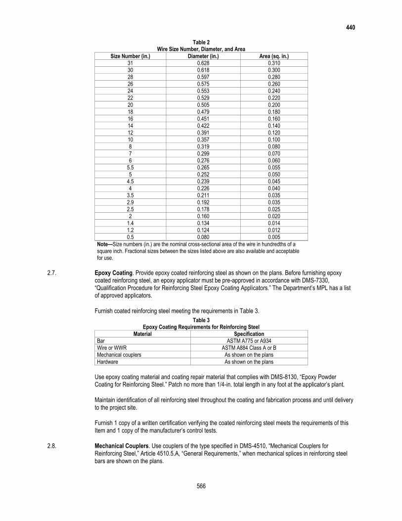
440
566
Table 2 Wire Size Number, Diameter, and Area
Size Number (in.) Diameter (in.) Area (sq. in.)
31 0.628 0.310
30 0.618 0.300
28 0.597 0.280
26 0.575 0.260
24 0.553 0.240
22 0.529 0.220
20 0.505 0.200
18 0.479 0.180
16 0.451 0.160
14 0.422 0.140
12 0.391 0.120
10 0.357 0.100
8 0.319 0.080
7 0.299 0.070
6 0.276 0.060
5.5 0.265 0.055
5 0.252 0.050
4.5 0.239 0.045
4 0.226 0.040
3.5 0.211 0.035
2.9 0.192 0.035
2.5 0.178 0.025
2 0.160 0.020
1.4 0.134 0.014
1.2 0.124 0.012
0.5 0.080 0.005
Note—Size numbers (in.) are the nominal cross-sectional area of the wire in hundredths of a square inch. Fractional sizes between the sizes listed above are also available and acceptable for use.
2.7. Epoxy Coating. Provide epoxy coated reinforcing steel as shown on the plans. Before furnishing epoxy coated reinforcing steel, an epoxy applicator must be pre-approved in accordance with DMS-7330, “Qualification Procedure for Reinforcing Steel Epoxy Coating Applicators.” The Department’s MPL has a list of approved applicators.
Furnish coated reinforcing steel meeting the requirements in Table 3.
Table 3 Epoxy Coating Requirements for Reinforcing Steel
Material Specification
Bar ASTM A775 or A934
Wire or WWR ASTM A884 Class A or B
Mechanical couplers As shown on the plans
Hardware As shown on the plans
Use epoxy coating material and coating repair material that complies with DMS-8130, “Epoxy Powder Coating for Reinforcing Steel.” Patch no more than 1/4-in. total length in any foot at the applicator’s plant.
Maintain identification of all reinforcing steel throughout the coating and fabrication process and until delivery to the project site.
Furnish 1 copy of a written certification verifying the coated reinforcing steel meets the requirements of this Item and 1 copy of the manufacturer’s control tests.
2.8. Mechanical Couplers. Use couplers of the type specified in DMS-4510, “Mechanical Couplers for Reinforcing Steel,” Article 4510.5.A, “General Requirements,” when mechanical splices in reinforcing steel bars are shown on the plans.
440
567
Furnish only couplers pre-qualified in accordance with DMS-4510, “Mechanical Couplers for Reinforcing Steel.” Ensure sleeve-wedge type couplers are not used on coated reinforcing. Sample and test couplers for use on individual projects in accordance with DMS-4510, “Mechanical Couplers for Reinforcing Steel.” Furnish couplers only at locations shown on the plans.
Furnish couplers for stainless reinforcing steel with the same alloy designation as the reinforcing steel.
2.9. Fibers. Supply fibers conforming to DMS-4550 “Fibers for Concrete” at the minimum dosage listed in the Department’s MPL, when allowed by the plans. Use non-metallic fibers when shown on the plans.
2.10. Stainless Reinforcing Steel. Provide deformed steel bars of the types listed in Table 4 and conforming to ASTM A955, Grade 60 or higher when stainless reinforcing steel is required on the plans.
Table 4 Acceptable Types of Deformed Stainless Steel Bar
UNS Designation S31653 S31803 S24100 S32304
AISI Type 316LN 2205 XM-28 2304
2.11. Low Carbon/Chromium Reinforcing Steel. Provide deformed steel bars conforming to ASTM A1035, Grade 100 when low carbon/chromium reinforcing steel is required on the plans.
2.12. Dual-Coated Reinforcing Steel. Provide deformed bars conforming to ASTM A1055, Grade 60 or higher when dual-coated reinforcing steel is required on the plans.
2.13. Glass Fiber Reinforced Polymer Bars (GFRP). Provide bars conforming to the AASHTO LRFD Bridge Design Guide Specifications for GFRP-Reinforced Concrete Bridge Decks and Traffic Railings, Section 4, “Material Specifications” when GFRP bars are required on the plans. Provide sample certification demonstrating the GFRP bar supplier has produced bar that meets the Material Specifications 2 mo. before fabrication. Furnish certification upon shipment that the GFRP bar supplied meets the Material Specifications.
3. CONSTRUCTION
3.1. Bending. Fabricate reinforcing steel bars as prescribed in the CRSI Manual of Standard Practice to the shapes and dimensions shown on the plans. Fabricate in the shop if possible. Field-fabricate, if permitted, using a method approved by the Engineer. Replace improperly fabricated, damaged, or broken bars at no additional expense to the Department. Repair damaged or broken bars embedded in a previous concrete placement using a method approved by the Engineer.
Unless otherwise shown on the plans, the inside diameter of bar bends, in terms of the nominal bar diameter (d), must be as shown in Table 5.
Table 5 Minimum Inside Diameter of Bar Bends
Bend Bar Size Number (in.) Pin Diameter
Bends of 90 and greater in stirrups, ties, and other secondary bars that enclose another bar in the bend
3, 4, 5 4d
6, 7, 8 6d
Bends in main bars and in secondary bars not covered above
3 through 8 6d
9, 10, 11 8d
14, 18 10d
Bend-test representative specimens as described for smaller bars in the applicable ASTM specification where bending No. 14 or No. 18 Grade 60 bars is required. Make the required 90° bend around a pin with a diameter of 10 times the nominal diameter of the bar.
Bend stainless reinforcing steel in accordance with ASTM A955.
3.2. Tolerances. Fabrication tolerances for bars are shown in Figure 1.
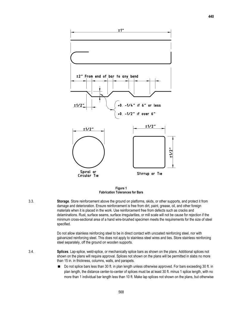
440
568
Figure 1
Fabrication Tolerances for Bars
3.3. Storage. Store reinforcement above the ground on platforms, skids, or other supports, and protect it from damage and deterioration. Ensure reinforcement is free from dirt, paint, grease, oil, and other foreign materials when it is placed in the work. Use reinforcement free from defects such as cracks and delaminations. Rust, surface seams, surface irregularities, or mill scale will not be cause for rejection if the minimum cross-sectional area of a hand wire-brushed specimen meets the requirements for the size of steel specified.
Do not allow stainless reinforcing steel to be in direct contact with uncoated reinforcing steel, nor with galvanized reinforcing steel. This does not apply to stainless steel wires and ties. Store stainless reinforcing steel separately, off the ground on wooden supports.
3.4. Splices. Lap-splice, weld-splice, or mechanically splice bars as shown on the plans. Additional splices not shown on the plans will require approval. Splices not shown on the plans will be permitted in slabs no more than 15 in. in thickness, columns, walls, and parapets.
Do not splice bars less than 30 ft. in plan length unless otherwise approved. For bars exceeding 30 ft. in
plan length, the distance center-to-center of splices must be at least 30 ft. minus 1 splice length, with no
more than 1 individual bar length less than 10 ft. Make lap splices not shown on the plans, but otherwise
440
569
permitted, in accordance with Table 6. Maintain the specified concrete cover and spacing at splices, and
place the lap-spliced bars in contact, securely tied together.
Table 6 Minimum Lap Requirements for Steel Bar Sizes through No. 11
Bar Size Number (in.) Uncoated Lap Length Coated Lap Length
3 1 ft. 4 in. 2 ft. 0 in.
4 1 ft. 9 in. 2 ft. 8 in.
5 2 ft. 2 in. 3 ft. 3 in.
6 2 ft. 7 in. 3 ft. 11 in.
7 3 ft. 5 in. 5 ft. 2 in.
8 4 ft. 6 in. 6 ft. 9 in.
9 5 ft. 8 in. 8 ft. 6 in.
10 7 ft. 3 in. 10 ft. 11 in.
11 8 ft. 11 in. 13 ft. 5 in.
Do not lap No. 14 or No. 18 bars.
Lap spiral steel at least 1 turn.
Splice WWR using a lap length that includes the overlap of at least 2 cross wires plus 2 in. on each
sheet or roll. Splices using bars that develop equivalent strength and are lapped in accordance with
Table 6 are permitted.
Lap the existing longitudinal bars with the new bars as shown in Table 6 for box culvert extensions with
less than 1 ft. of fill. Lap at least 1 ft. 0 in. for extensions with more than 1 ft. of fill.
Ensure welded splices conform to the requirements of the plans and of Item 448, “Structural Field
Welding.” Field-prepare ends of reinforcing bars if they will be butt-welded. Delivered bars must be long
enough to permit weld preparation.
Install mechanical coupling devices in accordance with the manufacturer’s recommendations at
locations shown on the plans. Protect threaded male or female connections, and ensure the threaded
connections are clean when making the connection. Do not repair damaged threads.
Mechanical coupler alternate equivalent strength arrangements, to be accomplished by substituting
larger bar sizes or more bars, will be considered if approved in writing before fabrication of the systems.
3.5. Placing. Place reinforcement as near as possible to the position shown on the plans. Do not vary bars from plan placement by more than 1/12 of the spacing between bars in the plane of the bar parallel to the nearest surface of concrete. Do not vary bars from plan placement by more than 1/4 in in the plane of the bar perpendicular to the nearest surface of concrete. Provide a minimum 1-in. clear cover of concrete to the nearest surface of bar unless otherwise shown on the plans.
For bridge slabs, the clear cover tolerance for the top mat of reinforcement is −0, +1/2 in.
Locate the reinforcement accurately in the forms, and hold it firmly in place before and during concrete placement by means of bar supports that are adequate in strength and number to prevent displacement and keep the reinforcement at the proper distance from the forms. Provide bar supports in accordance with the CRSI Manual of Standard Practice. Use Class 1 supports, approved plastic bar supports, precast mortar, or concrete blocks when supports are in contact with removable or stay-in-place forms. Use Class 3 supports in slab overlays on concrete panels or on existing concrete slabs. Bar supports in contact with soil or subgrade must be approved.
Use Class 1A supports with epoxy coated reinforcing steel. Provide epoxy or plastic coated tie wires and clips for use with epoxy coated reinforcing steel.
Use mortar or concrete with a minimum compressive strength of 5,000 psi for precast bar supports. Provide a suitable tie wire in each block for anchoring to the bar.
Place individual bar supports in rows at 4-ft. maximum spacing in each direction. Place continuous type bar supports at 4-ft. maximum spacing. Use continuous bar supports with permanent metal deck forms.
440
570
The exposure of the ends of longitudinals, stirrups, and spacers used to position the reinforcement in concrete pipe and storm drains is not cause for rejection.
Tie reinforcement for bridge slabs and top slabs of direct traffic culverts at all intersections, except tie only alternate intersections where spacing is less than 1 ft. in each direction. Tie the bars at enough intersections to provide a rigid cage of reinforcement for reinforcement cages for other structural members. Fasten mats of WWR securely at the ends and edges.
Clean mortar, mud, dirt, debris, oil, and other foreign material from the reinforcement before concrete placement. Do not place concrete until authorized.
Stop placement until corrective measures are taken if reinforcement is not adequately supported or tied to resist settlement, reinforcement is floating upward, truss bars are overturning, or movement is detected in any direction during concrete placement.
3.6. Handling, Placing, and Repairing Epoxy Coated Reinforcing Steel.
3.6.1. Handling. Provide systems for handling coated reinforcing steel with padded contact areas. Pad bundling bands or use suitable banding to prevent damage to the coating. Lift bundles of coated reinforcement with a strongback, spreader bar, multiple supports, or a platform bridge. Transport the bundled reinforcement carefully, and store it on protective cribbing. Do not drop or drag the coated reinforcement.
3.6.2. Placing. Do not flame-cut coated reinforcement. Saw or shear-cut only when approved. Coat cut ends as specified in Section 440.3.6.3., “Repairing Coating.”
Do not weld or mechanically couple coated reinforcing steel except where specifically shown on the plans. Remove the epoxy coating at least 6 in. beyond the weld limits before welding and 2 in. beyond the limits of the coupler before assembly. Clean the steel of oil, grease, moisture, dirt, welding contamination (slag or acid residue), and rust to a near-white finish after welding or coupling. Check the existing epoxy for damage. Remove any damaged or loose epoxy back to sound epoxy coating.
Coat the splice area after cleaning with epoxy repair material to a thickness of 7 to 17 mils after curing. Apply a second application of repair material to the bar and coupler interface to ensure complete sealing of the joint.
3.6.3. Repairing Coating. Use material that complies with the requirements of this Item and ASTM D3963 for repairing of the coating. Make repairs in accordance with procedures recommended by the manufacturer of the epoxy coating powder. Apply at least the same coating thickness as required for the original coating for areas to be patched. Repair all visible damage to the coating.
Repair sawed and sheared ends, cuts, breaks, and other damage promptly before additional oxidation occurs. Clean areas to be repaired to ensure they are free from surface contaminants. Make repairs in the shop or field as required.
3.7. Handling and Placing Stainless Reinforcing Steel. Handle, cut, and place stainless reinforcing steel bar using tools that are not used on carbon steel. Do not use carbon steel tools, chains, slings, etc. when handling stainless steel. Use only nylon or polypropylene slings. Cut stainless steel reinforcing using shears, saws, abrasive cutoff wheels, or torches. Remove any thermal oxidation using pickling paste. Do not field bend stainless steel reinforcing without approval.
Use 16 gauge fully annealed stainless steel tie wire conforming to the material properties listed in Section 440.2.10., “Stainless Reinforcing Steel.” Support all stainless reinforcing steel on solid plastic, stainless steel, or epoxy coated steel chairs. Do not use uncoated carbon steel chairs in contact with stainless reinforcing steel.

440
571
3.8. Bending, Handling, Repairing, and Placing GFRP Bars. Fabricate, handle, repair, and place GFRP bars in accordance with the AASHTO LRFD Bridge Design Guide Specifications for GFRP-Reinforced Concrete Bridge Decks and Traffic Railings, Section 5, Construction Specifications.
4. MEASUREMENT AND PAYMENT
The work performed, materials furnished, equipment, labor, tools, and incidentals will not be measured or paid for directly but will be considered subsidiary to pertinent Items.

(THIS PAGE IS INTENTIONALLY LEFT BLANK)
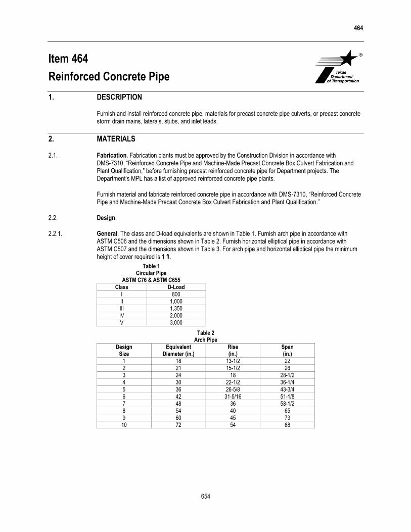
464
654
Item 464
Reinforced Concrete Pipe
1. DESCRIPTION
Furnish and install reinforced concrete pipe, materials for precast concrete pipe culverts, or precast concrete storm drain mains, laterals, stubs, and inlet leads.
2. MATERIALS
2.1. Fabrication. Fabrication plants must be approved by the Construction Division in accordance with DMS-7310, “Reinforced Concrete Pipe and Machine-Made Precast Concrete Box Culvert Fabrication and Plant Qualification,” before furnishing precast reinforced concrete pipe for Department projects. The Department’s MPL has a list of approved reinforced concrete pipe plants.
Furnish material and fabricate reinforced concrete pipe in accordance with DMS-7310, “Reinforced Concrete Pipe and Machine-Made Precast Concrete Box Culvert Fabrication and Plant Qualification.”
2.2. Design.
2.2.1. General. The class and D-load equivalents are shown in Table 1. Furnish arch pipe in accordance with ASTM C506 and the dimensions shown in Table 2. Furnish horizontal elliptical pipe in accordance with ASTM C507 and the dimensions shown in Table 3. For arch pipe and horizontal elliptical pipe the minimum height of cover required is 1 ft.
Table 1 Circular Pipe
ASTM C76 & ASTM C655
Class D-Load
I 800
II 1,000
III 1,350
IV 2,000
V 3,000
Table 2 Arch Pipe
Design Size
Equivalent Diameter (in.)
Rise (in.)
Span (in.)
1 18 13-1/2 22
2 21 15-1/2 26
3 24 18 28-1/2
4 30 22-1/2 36-1/4
5 36 26-5/8 43-3/4
6 42 31-5/16 51-1/8
7 48 36 58-1/2
8 54 40 65
9 60 45 73
10 72 54 88

464
655
Table 3 Horizontal Elliptical Pipe
Design Size
Equivalent Diameter (in.)
Rise (in.)
Span (in.)
1 18 14 23
2 24 19 30
3 27 22 34
4 30 24 38
5 33 27 42
6 36 29 45
7 39 32 49
8 42 34 53
9 48 38 60
10 54 43 68
2.2.2. Jacking, Boring, or Tunneling. Design pipe for jacking, boring, or tunneling considering the specific installation conditions such as the soil conditions, installation methods, anticipated deflection angles, and jacking stresses. Provide design notes and drawings signed and sealed by a Texas licensed professional engineer when requested.
2.3. Marking. Furnish each section of reinforced concrete pipe marked with the following information specified in DMS-7310, “Reinforced Concrete Pipe and Machine-Made Precast Concrete Box Culvert Fabrication and Plant Qualification.”
class or D-load of pipe,
ASTM designation,
date of manufacture,
pipe size,
name or trademark of fabricator and plant location,
designated fabricator’s approval stamp,
pipe to be used for jacking and boring (when applicable), and
designation “SR” for pipe meeting sulfate-resistant concrete plan requirements (when applicable).
Clearly mark 1 end of each section during the process of manufacture or immediately thereafter for pipe with elliptical reinforcement. Mark the pipe on the inside and outside of opposite walls to show the location of the top or bottom of the pipe as it should be installed unless the external shape of the pipe is such that the correct position of the top and bottom is obvious. Mark the pipe section by indenting or painting with waterproof paint.
2.4. Inspection. Provide access for inspection of the finished pipe at the project site before and during installation.
2.5. Causes for Rejection. Individual section of pipe may be rejected for any of the conditions stated in the Annex of DMS-7310, “Reinforced Concrete Pipe and Machine-Made Precast Concrete Box Culvert Fabrication and Plant Qualification.”
2.6. Repairs. Make repairs if necessary as stated in the Annex of DMS-7310, “Reinforced Concrete Pipe and Machine-Made Precast Concrete Box Culvert Fabrication and Plant Qualification.”
2.7. Jointing Materials. Use any of the following materials for the making of joints unless otherwise shown on the plans. Furnish a manufacturer’s certificate of compliance for all jointing materials except mortar.
2.7.1. Mortar. Provide mortar for joints that meets the requirements of Section 464.3.3., “Jointing.”
2.7.2. Cold-Applied, Plastic Asphalt Sewer Joint Compound. Provide a material that consists of natural or processed asphalt base, suitable volatile solvents, and inert filler. Ensure the consistency is such that the ends of the pipe can be coated with a layer of the compound up to 1/2 in. thick by means of a trowel. Provide
464
656
a joint compound that cures to a firm, stiff plastic condition after application. Provide a material of a uniform mixture. Stir any small separation found in the container into a uniform mix before using.
Provide a material that meets the requirements of Table 4 when tested in accordance with Tex-526-C.
Table 4 Cold-Applied, Plastic Asphalt Sewer Joint Compound Material Requirements
Composition Analysis
Asphalt base, 100%–% volatiles–% ash, % by weight 28–45
Volatiles, 212°F evaporation, 24 hr., % by weight 10–26
Mineral matter, determined as ash, % by weight 30–55
Consistency, cone penetration, 150 q, 5 sec., 77°F 150–275
2.7.3. Rubber Gaskets. Provide gaskets that conform to ASTM C1619 Class A or C. Meet the requirements of ASTM C443 for design of the pipe joints and permissible variations in dimensions.
2.7.4. Pre-Formed Flexible Joint Sealants. Pre-formed flexible joint sealants may be used for sealing joints of tongue-and-groove concrete pipe. Provide flexible joint sealants that meet the requirements of ASTM C990. Use flexible joint sealants that do not depend on oxidizing, evaporating, or chemical action for its adhesive or cohesive strength. Supply in extruded rope form of suitable cross-section. Provide a size of the pre-formed flexible joint sealant in accordance with the manufacturer’s recommendations and large enough to properly seal the joint. Protect flexible joint sealants with a suitable wrapper able to maintain the integrity of the jointing material when the wrapper is removed.
3. CONSTRUCTION
3.1. Excavation, Shaping, Bedding, and Backfill. Excavate, shape, bed, and backfill in accordance with Item 400, “Excavation and Backfill for Structures,” except where jacking, boring, or tunneling methods are permitted. Jack, bore, or tunnel the pipe in accordance with Item 476, “Jacking, Boring, or Tunneling Pipe or Box.” Immediate backfilling is permitted if joints consist of materials other than mortar. Take special precautions in placing and compacting the backfill to avoid any movement of the pipe or damage to the joints. Do not use heavy earth-moving equipment to haul over the structure until a minimum of 4 ft. of permanent or temporary compacted fill has been placed over the structure unless otherwise shown on the plans or permitted in writing. Remove and replace pipe damaged by the Contractor at no expense to the Department.
3.2. Laying Pipe. Start the laying of pipe on the bedding at the outlet end with the spigot or tongue end pointing downstream, and proceed toward the inlet end with the abutting sections properly matched, true to the established lines and grades unless otherwise authorized. Fit, match, and lay the pipe to form a smooth, uniform conduit. Cut cross trenches in the foundation to allow the barrel of the pipe to rest firmly upon the bedding where bell-and-spigot pipe is used. Cut cross trenches no more than 2 in. larger than the bell ends of the pipe. Lower sections of pipe into the trench without damaging the pipe or disturbing the bedding and the sides of the trench. Carefully clean the ends of the pipe before the pipe is placed. Prevent the earth or bedding material from entering the pipe as it is laid. Lay the pipe in the trench, when elliptical pipe with circular reinforcing or circular pipe with elliptical reinforcing is used, so the markings for the top or bottom are not more than 5° from the vertical plane through the longitudinal axis of the pipe. Remove and re-lay, without extra compensation, pipe that is not in alignment or shows excessive settlement after laying.
Lay multiple lines of reinforced concrete pipe with the centerlines of the individual barrels parallel. Use the clear distances between outer surfaces of adjacent pipes shown in Table 5 unless otherwise shown on the plans. Use the equivalent diameter from Table 2 or Table 3 for arch pipe or horizontal elliptical pipe to determine the clear distance requirement in Table 5.
464
657
Table 5 Minimum Clear Distance between Pipes
Equivalent Diameter Min Clear Distance
18 in. 9 in.
24 in. 11 in.
30 in. 1 ft. 1 in.
36 in. 1 ft. 3 in.
42 in. 1 ft. 5 in.
48 in. 1 ft. 7 in.
54 in. 1 ft. 11 in.
60 to 84 in. 2 ft.
3.3. Jointing. Make available an appropriate rolling device similar to an automobile mechanic’s “creeper” for conveyance through small-size pipe structures.
3.3.1. Joints Sealed with Hydraulic Cement Mortar. Use Type S mortar meeting the requirements of ASTM C270. Clean and wet the pipe ends before making the joint. Plaster the lower half of the bell or groove and the upper half of the tongue or spigot with mortar. Pack mortar into the joint from both inside and outside the pipe after the pipes are tightly jointed. Finish the inside smooth and flush with adjacent joints of pipe. Form a bead of semicircular cross-section over tongue-and-groove joints outside the pipe, extending at least 1 in. on each side of the joint. Form the mortar for bell-and-spigot joints to a 45° fillet between the outer edge of the bell and the spigot. Cure mortar joints by keeping the joints wet for at least 48 hr. or until the backfill has been completed, whichever comes first. Place fill or backfill once the mortar jointing material has cured for at least 6 hr. Conduct jointing only when the atmospheric temperature is above 40°F. Protect mortared joints against freezing by backfilling or other approved methods for at least 24 hr.
Driveway culverts do not require mortar banding on the outside of the pipe.
Furnish pipes, with approval, that are large enough for a person to enter with the groove between 1/2 in. and 3/4 in. longer than the tongue. Such pipe may be laid and backfilled without mortar joints. Clean the space on the interior of the pipe between the end of the tongue and the groove of all foreign material, thoroughly wet and fill with mortar around the entire circumference of the pipe, and finish flush after the backfilling has been completed.
3.3.2. Joints Using Cold-Applied, Plastic Asphalt Sewer Joint Compound. Ensure both ends of the pipes are clean and dry. Trowel or otherwise place a 1/2–in. thick layer of the compound in the groove end of the pipe covering at least 2/3 of the joint face around the entire circumference. Shove home the tongue end of the next pipe with enough pressure to make a tight joint. Remove any excess mastic projecting into the pipe after the joint is made. Backfill after the joint has been inspected and approved.
3.3.3. Joints Using Rubber Gaskets. Make the joint assembly according to the recommendations of the gasket manufacturer. Make joints watertight when using rubber gaskets. Backfill after the joint has been inspected and approved.
3.3.4. Joints Using Pre-Formed Flexible Joint Sealants. Install pre-formed flexible joint sealants in accordance with the manufacturer’s recommendations. Place the joint sealer so no dirt or other deleterious materials come in contact with the joint sealing material. Pull or push home the pipe with enough force to properly seal the joint. Remove any joint material pushed out into the interior of the pipe that would tend to obstruct the flow. Store pre-formed flexible joint sealants in an area warmed naturally or artificially to above 70°F in an approved manner when the atmospheric temperature is below 60°F. Apply flexible joint sealants to pipe joints immediately before placing pipe in trench, and connect pipe to previously laid pipe. Backfill after the joint has been inspected and approved.
3.4. Connections and Stub Ends. Make connections of concrete pipe to existing pipes, pipe storm drains, or storm drain appurtenances as shown on the plans.
Mortar or concrete the bottom of existing structures if necessary to eliminate any drainage pockets created by the connections. Repair any damage to the existing structure resulting from making the connections.
464
658
Make connections between concrete pipe and corrugated metal pipe with a suitable concrete collar and a minimum thickness of 4 in. unless otherwise shown on the plans.
Finish stub ends for connections to future work not shown on the plans by installing watertight plugs into the free end of the pipe.
Fill lift holes with concrete, mortar, or precast concrete plugs after the pipe is in place.
4. MEASUREMENT
This Item will be measured by the foot. Measurement will be made between the ends of the pipe barrel along the flow line, not including safety end treatments. Safety end treatments will be measured in accordance with Item 467, “Safety End Treatment.” Pipe that will be jacked, bored, or tunneled will be measured in accordance with Item 476, “Jacking, Boring, or Tunneling Pipe or Box.” Measurement of spurs, branches, or new connecting pipe will be made from the intersection of the flow line with the outside surface of the pipe into which it connects. Where inlets, headwalls, catch basins, manholes, junction chambers, or other structures are included in lines of pipe, the length of pipe tying into the structure wall will be included for measurement, but no other portion of the structure length or width will be included.
For multiple pipes, the measured length will be the sum of the lengths of the barrels.
This is a plans quantity measurement Item. The quantity to be paid is the quantity shown in the proposal unless modified by Article 9.2., “Plans Quantity Measurement.” Additional measurements or calculations will be made if adjustments of quantities are required.
5. PAYMENT
The work performed and materials furnished in accordance with this Item and measured as provided under “Measurement” will be paid for at the unit price bid for “Reinforced Concrete Pipe,” “Reinforced Concrete Pipe (Arch),” or “Reinforced Concrete Pipe (Elliptical)” of the size and D-load specified or of the size and class specified. This price is full compensation for constructing, furnishing, transporting, placing, and joining pipes; shaping the bed; cutting pipes on skew or slope; connecting to new or existing structures; breaking back, removing, and disposing of portions of the existing structure; replacing portions of the existing structure; cutting pipe ends on skew or slope; and equipment, labor, tools, and incidentals.
Protection methods for excavations greater than 5 ft. deep will be measured and paid for as required under Item 402, “Trench Excavation Protection,” or Item 403, “Temporary Special Shoring.” Excavation, shaping, bedding, and backfill will be paid for in accordance with Item 400, “Excavation and Backfill for Structures.” When jacking, boring, or tunneling is used at the Contractor’s option, payment will be made under this Item. When jacking, boring or tunneling is required, payment will be made under Item 476, “Jacking, Boring or Tunneling Pipe or Box.”

(THIS PAGE IS INTENTIONALLY LEFT BLANK)
466
663
Item 466
Headwalls and Wingwalls
1. DESCRIPTION
Furnish, construct, and install concrete headwalls and wingwalls for drainage structures and underpasses.
2. MATERIALS
2.1. General. Furnish materials in accordance with the following.
Item 420, “Concrete Substructures,”
Item 421, “Hydraulic Cement Concrete,” and
Item 440, “Reinforcement for Concrete.”
Use Class C concrete for cast-in-place and precast concrete units unless otherwise shown on the plans. Furnish cast-in-place or precast headwalls and wingwalls unless otherwise shown on the plans.
2.2. Fabrication.
2.2.1. General. Fabricate cast-in-place concrete units and precast units in accordance with Item 420 “Concrete Substructures.” Use the following definitions for headwalls and wingwalls:
“Headwalls” refers to all walls, including wings, at the ends of single-barrel and multiple-barrel pipe
culvert structures.
“Wingwalls” refers to all walls at the ends of single-barrel or multiple-barrel box culvert structures.
2.2.2. Lifting Holes. Provide no more than 4 lifting holes in each section for precast units. Lifting holes may be cast, cut into fresh concrete after form removal, or drilled. Provide lifting holes large enough for adequate lifting devices based on the size and weight of the section. The maximum hole diameter is 3 in. at the inside surface of the wall and 4 in. at the outside surface. Cut no more than 1 longitudinal wire or 2 circumferential wires per layer of reinforcing steel when locating lift holes. Repair spalled areas around lifting holes.
2.2.3. Marking. Clearly mark each precast unit before shipment from the casting or fabrication yard with the following:
the date of manufacture,
the name or trademark of the manufacturer, and
the type and size designation.
2.2.4. Storage and Shipment. Store precast units on a level surface. Do not place any loads on precast concrete units until design strength is reached. Do not ship units until design strength requirements have been met.
2.2.5. Causes for Rejection. Precast units may be rejected for not meeting any one of the specification requirements. Individual units may also be rejected for fractures or cracks passing through the wall or surface defects indicating honeycombed or open texture surfaces. Remove rejected units from the project, and replace them with acceptable units meeting the requirements of this Item.
2.2.6. Defects and Repairs. Occasional imperfections in manufacture or accidental damage sustained during handling may be repaired. The repaired units will be acceptable if they conform to the requirements of this Item and the repairs are sound, properly finished, and cured in conformance with pertinent specifications.
466
664
3. CONSTRUCTION
3.1. General. Remove portions of existing structures and drill, dowel, and grout in accordance with Item 420, “Concrete Substructures.”
3.2. Excavation, Shaping, Bedding, and Backfill. Excavate, shape, bed, and backfill in accordance with Item 400, “Excavation and Backfill for Structures.” Take special precautions in placing and compacting the backfill to avoid any movement or damage to the units. Bed precast units on foundations of firm and stable material accurately shaped to conform to the bases of the units.
3.3. Placement of Precast Units. Provide adequate means to lift and place the precast units. Fill lifting holes with mortar or concrete and cure. Precast concrete or mortar plugs may be used.
3.4. Connections. Make connections to new or existing structures in accordance with the details shown on the plans. Furnish jointing material in accordance with Item 464, “Reinforced Concrete Pipe,” or as shown on the plans.
Remove a length of the existing pipe from the headwall to the joint when removing existing headwalls as shown on the plans or as approved. Re-lay the removed pipe if approved, or furnish and lay a length of new pipe.
4. MEASUREMENT
This is a plans quantity measurement item. The quantity to be paid is the quantity shown in the proposal unless modified by Article 9.2., “Plans Quantity Measurement.” Additional measurements or calculations will be made if adjustments of quantities are required.
4.1. Headwalls. Headwalls will be measured by each end of a structure.
4.2. Wingwalls. Wingwalls will be measured by one of the following methods:
4.2.1. Square Foot. Wingwalls will be measured by the square foot of the front surface area of the wall of each type. The area will be measured from the top of the footing or apron to the top of the wall unless otherwise shown on the plans. If there is no footing or apron, then measurement is from the bottom of the wall.
4.2.2. Each. Wingwalls will be measured by each end of a structure.
5. PAYMENT
The work performed and materials furnished in accordance with this Item and measured as provided under “Measurement” will be paid for at the price bid for “Headwalls” of the type and pipe size (diameter or design) specified, “Wingwalls” of the type specified when measurement is by the square foot, or “Wingwalls” of the type and wall height specified when measurement is by each. For payment purposes, the wingwall height will be rounded to the nearest foot. All wingwalls and headwalls of the same type will be paid for equally when skew does not affect the type. This price is full compensation for constructing, furnishing, transporting, and installing the headwalls or wingwalls; connecting to existing structure; breaking back, removing and disposing of portions of the existing structure, and replacing portions of the existing structure as required to make connections; excavation and backfill; and concrete, reinforcing steel, corrugated metal pipe or reinforced concrete pipe, equipment, labor, tools, and incidentals.
Apron concrete or riprap between or around the wingwalls of single- or multiple-barrel box culvert structures will be measured and paid for in accordance with Item 432, “Riprap.”
The removal and re-laying of existing pipe or the furnishing of new pipe to replace existing pipe will not be paid for directly but will be considered subsidiary to this Item.

(THIS PAGE IS INTENTIONALLY LEFT BLANK)
467
665
Item 467
Safety End Treatment
1. DESCRIPTION
Furnish, construct, and install safety end treatments for drainage structures, or install or replace pipe runners or pipe runner assemblies on existing drainage structures.
2. MATERIALS
2.1. General. Furnish materials in accordance with the following.
Item 420, “Concrete Substructures,”
Item 421, “Hydraulic Cement Concrete,”
Item 432, “Riprap,”
Item 440, “Reinforcement for Concrete,”
Item 442, “Metal for Structures,”
Item 445, “Galvanizing,”
Item 460, “Corrugated Metal Pipe,” and
Item 464, “Reinforced Concrete Pipe.”
Use Class C concrete for cast-in-place and precast concrete units unless otherwise shown on the plans. Furnish cast-in-place or precast safety end treatments unless otherwise shown on the plans. Furnish Class B concrete for concrete riprap unless otherwise shown on the plans. Provide galvanized steel for prefabricated metal end sections in accordance with Item 460, “Corrugated Metal Pipe.”
Furnish pipe runners in accordance with the following:
ASTM A1085;
ASTM A53, Type E or S, Grade B;
ASTM A500, Grade B; or
API 5L, Grade X42.
Furnish plates and angles in accordance with ASTM A36. Furnish nuts and bolts in accordance with ASTM A307. Galvanize pipes, plates, angles, nuts, and bolts in accordance with Item 445, “Galvanizing.”
2.2. Fabrication. Fabricate cast-in-place concrete units and precast units in accordance with Item 420, “Concrete Substructures.” Provide either prefabricated metal end sections or mitered CMP when specified for the pipe structure unless otherwise shown on the plans.
Provide one of the following when reinforced concrete pipe (RCP) is specified for the pipe structure, unless otherwise shown on the plans:
mitered RCP or
precast safety end treatment (SET) units. Provide riprap only if the plans specifically require it for this
alternative.
2.2.1. SET Types.
2.2.1.1. Type I. Provide Type I SET consisting of reinforced concrete headwalls or wingwalls and pipe runners in accordance with the details shown on the plans when required.
467
666
2.2.1.2. Type II. Provide Type II SET in accordance with the details shown on the plans consisting of the following:
CMP or RCP mitered to the proper slope, concrete riprap and pipe runners, when required;
prefabricated metal end sections, concrete riprap and pipe runners, when required; or
precast SET units, concrete riprap, when required, and pipe runners, when required.
2.2.2. Lifting Holes. Provide no more than 4 lifting holes in each section for precast units. Lifting holes may be cast, cut into fresh concrete after form removal, or drilled. Provide lifting holes large enough for adequate lifting devices based on the size and weight of the section. The maximum hole diameter is 3 in. at the inside surface of the wall and 4 in. at the outside surface. Cut no more than 1 longitudinal wire or 2 circumferential wires per layer of reinforcing steel when locating lift holes. Repair spalled areas around lifting holes.
2.2.3. Marking. Clearly mark the following on each precast unit, mitered CMP, mitered RCP, or metal end section before shipment from the casting or fabrication yard:
the date of manufacture,
the name or trademark of the manufacturer, and
the type and size designation.
2.2.4. Storage and Shipment. Store precast units on a level surface. Do not place any loads on precast units until the design strength is reached. Do not ship units until design strength requirements have been met.
2.2.5. Causes for Rejection. Precast units may be rejected for not meeting any one of the specification requirements. Individual units may also be rejected for fractures or cracks passing through the wall or surface defects indicating honeycombed or open texture surfaces. Remove rejected units from the project and replace with acceptable units meeting the requirements of this Item.
2.2.6. Defects and Repairs. Occasional imperfections in manufacture or accidental damage sustained during handling may be repaired. The repaired units will be acceptable if they conform to the requirements of this Item and the repairs are sound and properly finished and cured in conformance with pertinent specifications. Repair damaged galvanizing in accordance with Section 445.3.5., “Repairs.”
3. CONSTRUCTION
3.1. General. Remove portions of existing structures in accordance with Section 420.4.8., “Extending Existing Substructures.” Drill, dowel, and grout in accordance with Item 420, “Concrete Substructures.” Furnish concrete riprap in accordance with Item 432, “Riprap.”
Provide riprap on all prefabricated metal end sections.
3.2. Excavation, Shaping, Bedding, and Backfill. Excavate, shape, bed, and backfill in accordance with Item 400, “Excavation and Backfill for Structures.” Take special precautions in placing and compacting the backfill to avoid any movement or damage to the units. Bed precast units on foundations of firm and stable material accurately shaped to conform to the bases of the units.
3.3. Placement of Precast Units. Provide adequate means to lift and place the precast units. Fill lifting holes with mortar or concrete and cure. Precast concrete or mortar plugs may be used.
3.4. Connections. Make connections to new or existing structures in accordance with the details shown on the plans. Furnish jointing material in accordance with Item 464, “Reinforced Concrete Pipe.”
Also remove a length of the existing pipe from the headwall to the joint when removing existing headwalls as shown on the plans or as approved. Re-lay the removed pipe if approved, or furnish and lay a length of new pipe.
3.5. Install or Replace Pipe Runners or Assemblies. Install or replace individual pipe runners or pipe runner assemblies on existing drainage structures as indicated on the plans.
467
667
4. MEASUREMENT
SETs of all types will be measured by each barrel of each structure end.
Pipe runners or pipe runner assemblies installed or replaced on existing structure will be measured by each installed or replaced on each structure end.
5. PAYMENT
The work performed and materials furnished in accordance with this Item and measured as provided under “Measurement” will be paid for at the unit price bid for the various designations of “Safety End Treatment” specified as follows:
SET (Type I) (Barrel Span) (Wall Height) (Slope, Horizontal:Vertical) (Orientation, Cross or Parallel)
SET (Type I) (Pipe Diameter or Design) (Slope, Horizontal:Vertical) (Orientation, Cross or Parallel)
SET (Type II) (Pipe Diameter or Design) (Pipe Material) (Slope, Horizontal:Vertical) (Orientation, Cross
or Parallel)
SET (Pipe Runner)
SET (Pipe Runner Assembly)
For payment purposes, the wingwall heights of Type I SETs for box culverts will be rounded to the nearest foot.
This price is full compensation for constructing, furnishing, transporting, and installing the end treatments; pipe runners, or pipe runner assemblies, connecting to existing structure; breaking back, removing and disposing of portions of the existing structure, removing and disposing of existng pipe runner or pipe runner assemblies, and replacing portions of the existing structure as required to make connections; excavation and backfill; furnishing concrete, reinforcing steel, corrugated metal pipe or reinforced concrete pipe, and pipe runners; and concrete riprap, nuts, bolts, plates, angles, equipment, labor, tools, and incidentals.
The removal and re-laying of existing pipe or the furnishing of new pipe to replace existing pipe will not be paid for directly but will be considered subsidiary to this Item.
The mitered length of CMP or RCP that is a part of the SET (Type II) will not be paid for directly but will be considered subsidiary to this Item. The limits for payment for pipe will be as shown on the plans and paid for in accordance with the pertinent bid item.
The limits of riprap to be included in the price bid for each SET will be shown on the plans. Any riprap placed beyond the limits shown will be paid in accordance with Item 432, “Riprap.” Riprap between multiple precast SET units will be required as shown on the plans and is included in the price bid for SET.
When precast SETs are provided as an option to mitered RCP, riprap aprons will not be required unless the plans specifically require riprap aprons for precast SET units. The plans will show the limits of the riprap to be included with the precast SET for payment.

PART C
GUIDE SCHEDULE OF SAMPLING AND TESTING

GUIDE SCHEDULE OF SAMPLING & TESTING
MAY 2016
1
Using the Guide Schedule
Research of sampling and testing rates listed for project tests in the following Guide Schedule show that the Department’s and the Contractor’s risk of
either rejecting “good” material or accepting “bad” material range from 20% to 40%.
To reduce this risk, we recommend that the sampling rate be increased during initial production. A four-fold increase in testing frequency will generally
reduce risk to approximately 5%. The intent of increasing testing at the start of production is to insure that the Contractor’s processes are in control and to
establish acceptability requirements early.
There is a need to increase the frequency of testing for high-variability materials and when testing results do not meet specifications. The Engineer may
require the Contractor to reimburse the Department for costs resulting from failing test results, in accordance with the specifications.
Materials incorporated in TxDOT projects are subjected to various quality assurance procedures such as testing (as outlined in this document), certification,
quality monitoring, approved lists, etc. The Engineer and testing staff should familiarize themselves with materials to be used before work begins by
reviewing the specifications and this document. Discuss material testing requirements with the Contractor.
Other testing required by the specifications, but not shown in the Guide Schedule, should be performed at a frequency necessary to provide adequate
confidence that materials meet specifications.
NOTE: For projects subject to FHWA construction oversight activities, use the “Letter of Certification of Materials Used" to document reasons for material
acceptance when a test fails. For all other projects, document the justification and explanation for acceptance of materials that fail project tests in the
project file.
Assuring the quality of the product and proper incorporation of materials into the project begins with proper sampling practices. Sampling, testing, and
construction inspection must be performed collaboratively to assure the specific attributes of the finished product reflect quality workmanship. Sampling
guidance for hot-mixed asphalt is contained in Tex-225-F, “Random Selection of Bituminous Mixture Samples,” and the respective specification for that
material. All remaining materials are covered by method and materials specifications, to which the following applies.
For acceptance testing, especially that which directly determines payment for the Contractor, sampling personnel should provide randomness in sampling
by avoiding patterned sampling routines. Examples of such sampling practices are as follows:
Soils/flexible base: Vary sampling between stockpiling operations, completed stockpile, windrow, and project site. Vary the time of day sampling is
performed.
Aggregates: Sample aggregates nearest the point of incorporation into the work. Vary sampling between stockpiling operations, completed
stockpile, belt sampling, and if deemed necessary, railroad cars/trucks. Vary the time of day sampling is performed.
Concrete (structural and miscellaneous: Always sample as near as practicable to the point of placement. For strength testing, vary the time of day
or the number of truck from which the concrete is sampled. Tests for slump, air, and temperature should be done often to ensure the consistent
control of the concrete production (not applicable to miscellaneous concrete).
This Guide Schedule is applicable to all contracts associated with the 2014 Standard Specifications.
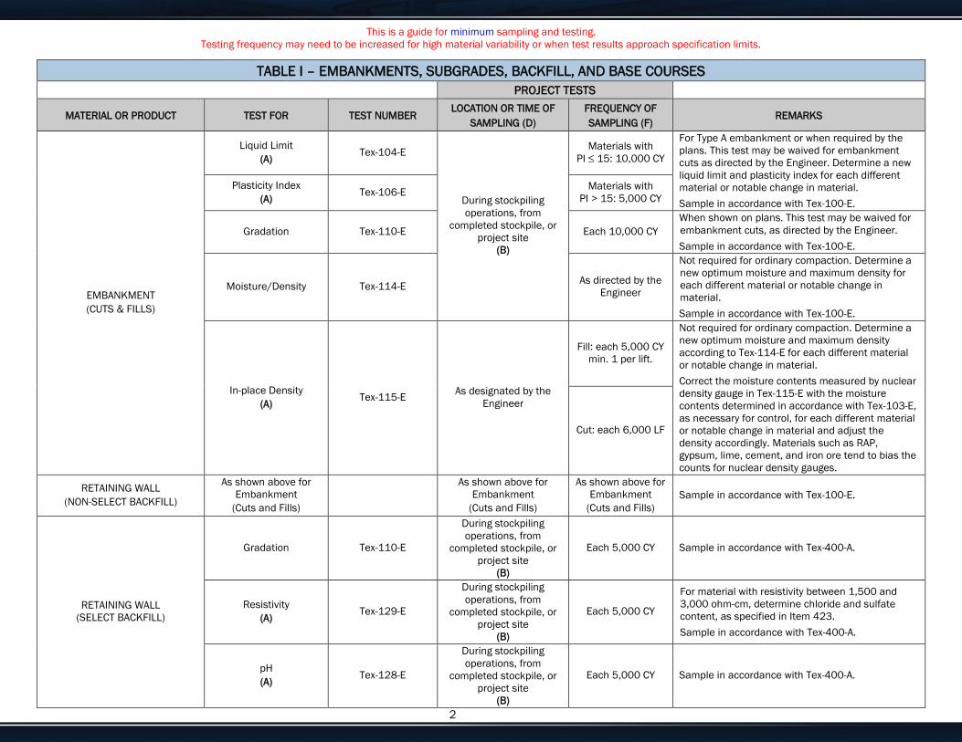
This is a guide for minimum sampling and testing.
Testing frequency may need to be increased for high material variability or when test results approach specification limits.
Enter customize text here for your needs or delete if not needed. 2
TABLE I – EMBANKMENTS, SUBGRADES, BACKFILL, AND BASE COURSES
PROJECT TESTS
MATERIAL OR PRODUCT TEST FOR TEST NUMBER LOCATION OR TIME OF
SAMPLING (D)
FREQUENCY OF
SAMPLING (F) REMARKS
EMBANKMENT
(CUTS & FILLS)
Liquid Limit
(A) Tex-104-E
During stockpiling
operations, from
completed stockpile, or
project site
(B)
Materials with
PI ≤ 15: 10,000 CY
For Type A embankment or when required by the
plans. This test may be waived for embankment
cuts as directed by the Engineer. Determine a new
liquid limit and plasticity index for each different
material or notable change in material.
Sample in accordance with Tex-100-E.
Plasticity Index
(A) Tex-106-E
Materials with
PI > 15: 5,000 CY
Gradation Tex-110-E Each 10,000 CY
When shown on plans. This test may be waived for
embankment cuts, as directed by the Engineer.
Sample in accordance with Tex-100-E.
Moisture/Density Tex-114-E As directed by the
Engineer
Not required for ordinary compaction. Determine a
new optimum moisture and maximum density for
each different material or notable change in
material.
Sample in accordance with Tex-100-E.
In-place Density
(A) Tex-115-E
As designated by the
Engineer
Fill: each 5,000 CY
min. 1 per lift.
Not required for ordinary compaction. Determine a
new optimum moisture and maximum density
according to Tex-114-E for each different material
or notable change in material.
Correct the moisture contents measured by nuclear
density gauge in Tex-115-E with the moisture
contents determined in accordance with Tex-103-E,
as necessary for control, for each different material
or notable change in material and adjust the
density accordingly. Materials such as RAP,
gypsum, lime, cement, and iron ore tend to bias the
counts for nuclear density gauges.
Cut: each 6,000 LF
RETAINING WALL
(NON-SELECT BACKFILL)
As shown above for
Embankment
(Cuts and Fills)
As shown above for
Embankment
(Cuts and Fills)
As shown above for
Embankment
(Cuts and Fills)
Sample in accordance with Tex-100-E.
RETAINING WALL
(SELECT BACKFILL)
Gradation Tex-110-E
During stockpiling
operations, from
completed stockpile, or
project site
(B)
Each 5,000 CY Sample in accordance with Tex-400-A.
Resistivity
(A) Tex-129-E
During stockpiling
operations, from
completed stockpile, or
project site
(B)
Each 5,000 CY
For material with resistivity between 1,500 and
3,000 ohm-cm, determine chloride and sulfate
content, as specified in Item 423.
Sample in accordance with Tex-400-A.
pH
(A) Tex-128-E
During stockpiling
operations, from
completed stockpile, or
project site
(B)
Each 5,000 CY Sample in accordance with Tex-400-A.
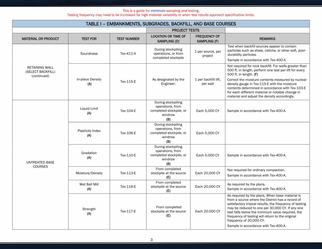
This is a guide for minimum sampling and testing.
Testing frequency may need to be increased for high material variability or when test results approach specification limits.
Enter customize text here for your needs or delete if not needed. 3
TABLE I – EMBANKMENTS, SUBGRADES, BACKFILL, AND BASE COURSES
PROJECT TESTS
MATERIAL OR PRODUCT TEST FOR TEST NUMBER LOCATION OR TIME OF
SAMPLING (D)
FREQUENCY OF
SAMPLING (F) REMARKS
RETAINING WALL
(SELECT BACKFILL)
(continued)
Soundness Tex-411-A
During stockpiling
operations, or from
completed stockpile
1 per source, per
project
Test when backfill sources appear to contain
particles such as shale, caliche, or other soft, poor-
durability particles.
Sample in accordance with Tex-400-A.
In-place Density
(A) Tex-115-E
As designated by the
Engineer.
1 per backfill lift,
per wall
Not required for rock backfill. For walls greater than
500 ft. in length, perform one test per lift for every
500 ft. in length. (F)
Correct the moisture contents measured by nuclear
density gauge in Tex-115-E with the moisture
contents determined in accordance with Tex-103-E
for each different material or notable change in
material and adjust the density accordingly.
UNTREATED BASE
COURSES
Liquid Limit
(A) Tex-104-E
During stockpiling
operations, from
completed stockpile, or
windrow
(B)
Each 5,000 CY Sample in accordance with Tex-400-A.
Plasticity Index
(A) Tex-106-E
During stockpiling
operations, from
completed stockpile, or
windrow
(B)
Each 5,000 CY
Gradation
(A) Tex-110-E
During stockpiling
operations, from
completed stockpile, or
windrow
(B)
Each 5,000 CY Sample in accordance with Tex-400-A.
Moisture/Density Tex-113-E
From completed
stockpile at the source
(E)
Each 20,000 CY Not required for ordinary compaction.
Sample in accordance with Tex-400-A.
Wet Ball Mill
(A) Tex-116-E
From completed
stockpile at the source
(E)
Each 20,000 CY As required by the plans.
Sample in accordance with Tex-400-A.
Strength
(A) Tex-117-E
From completed
stockpile at the source
(E)
Each 20,000 CY
As required by the plans. When base material is
from a source where the District has a record of
satisfactory triaxial results, the frequency of testing
may be reduced to one per 30,000 CY. If any one
test falls below the minimum value required, the
frequency of testing will return to the original
frequency of 20,000 CY.
Sample in accordance with Tex-400-A.

This is a guide for minimum sampling and testing.
Testing frequency may need to be increased for high material variability or when test results approach specification limits.
Enter customize text here for your needs or delete if not needed. 4
TABLE I – EMBANKMENTS, SUBGRADES, BACKFILL, AND BASE COURSES
PROJECT TESTS
MATERIAL OR PRODUCT TEST FOR TEST NUMBER LOCATION OR TIME OF
SAMPLING (D)
FREQUENCY OF
SAMPLING (F) REMARKS
UNTREATED BASE
COURSES
In-place Density
(A) Tex-115-E
As designated by the
Engineer
Each 3,000 CY,
min. 1 per lift
Correct the moisture contents measured by nuclear
density gauge in Tex-115-E with the moisture
contents determined in accordance with Tex-103-E,
as necessary for control, for each different material
or notable change in material and adjust the
density accordingly. Materials such as RAP,
gypsum, lime, cement, and iron ore tend to bias the
counts for nuclear density gauges.
Thickness
(A) Tex-140-E
As designated by the
Engineer Each 3,000 CY
Not required where survey grade control documents
compliance.
TREATED
SUBGRADE AND
BASE COURSES
SUBGRADE
BEFORE
TREATMENT
Organic Content Tex-148-E As designated by the
Engineer
1 per 500 linear
feet or 5,000 CY
Required for existing subgrade material and
material imported from a borrow source. Soil survey
and geologic maps may be used to determine
sampling locations.
Sample in accordance with Tex-100-E.
Sulfate Content Tex-145-E As designated by the
Engineer
1 per 500 linear
feet or 5,000 CY
Required for existing subgrade material and
material imported from a borrow source. Soil survey
and geologic maps may be used to determine
sampling locations.
Sample in accordance with Tex-100-E.
NEW BASE
MATERIAL
Liquid Limit
(A) Tex-104-E
During stockpiling
operations, from
completed stockpile, or
windrow
(B)
Each 5,000 CY
When central mix site or plant is used, windrow
sampling may be waived.
Sample in accordance with Tex-400-A.
Plasticity Index
(A) Tex-106-E
During stockpiling
operations, from
completed stockpile, or
windrow
(B)
Each 5,000 CY
Gradation
(A) Tex-110-E
During stockpiling
operations, from
completed stockpile, or
windrow
(B)
Each 5,000 CY Sample in accordance with Tex-400-A.
Wet Ball Mill
(A) Tex-116-E
From completed
stockpile at the source
(E)
Each 20,000 CY As required by the plans.
Sample in accordance with Tex-400-A.
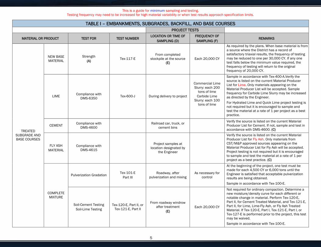
This is a guide for minimum sampling and testing.
Testing frequency may need to be increased for high material variability or when test results approach specification limits.
Enter customize text here for your needs or delete if not needed. 5
TABLE I – EMBANKMENTS, SUBGRADES, BACKFILL, AND BASE COURSES
PROJECT TESTS
MATERIAL OR PRODUCT TEST FOR TEST NUMBER LOCATION OR TIME OF
SAMPLING (D)
FREQUENCY OF
SAMPLING (F) REMARKS
TREATED
SUBGRADE AND
BASE COURSES
NEW BASE
MATERIAL
Strength
(A) Tex-117-E
From completed
stockpile at the source
(E)
Each 20,000 CY
As required by the plans. When base material is from
a source where the District has a record of
satisfactory triaxial results, the frequency of testing
may be reduced to one per 30,000 CY. If any one
test falls below the minimum value required, the
frequency of testing will return to the original
frequency of 20,000 CY.
LIME Compliance with
DMS-6350 Tex-600-J During delivery to project
Commercial Lime
Slurry: each 200
tons of lime
Carbide Lime
Slurry: each 100
tons of lime
Sample in accordance with Tex-400-A.Verify the
source is listed on the current Material Producer
List for Lime. Only materials appearing on the
Material Producer List will be accepted. Sample
frequency for Carbide Lime Slurry may be increased
as directed by the Engineer.
For Hydrated Lime and Quick Lime project testing is
not required but it is encouraged to sample and
test the material at a rate of 1 per project as a best
practice.
CEMENT Compliance with
DMS-4600
Railroad car, truck, or
cement bins
Verify the source is listed on the current Material
Producer List for Cement. If not, sample and test in
accordance with DMS-4600. (C)
FLY ASH
MATERIAL
Compliance with
DMS-4615
Project samples at
location designated by
the Engineer
Verify the source is listed on the current Material
Producer List for Fly Ash. Only materials from
CST/M&P approved sources appearing on the
Material Producer List for Fly Ash will be accepted.
Project testing is not required but it is encouraged
to sample and test the material at a rate of 1 per
project as a best practice. (C)
COMPLETE
MIXTURE
Pulverization Gradation Tex-101-E
Part III
Roadway, after
pulverization and mixing
As necessary for
control
At the beginning of the project, one test must be
made for each 4,500 CY or 6,000 tons until the
Engineer is satisfied that acceptable pulverization
results are being obtained.
Sample in accordance with Tex-100-E.
Soil-Cement Testing
Soil-Lime Testing
Tex-120-E, Part II, or
Tex-121-E, Part II
From roadway windrow
after treatment
(E)
Each 20,000 CY
Not required for ordinary compaction. Determine a
new moisture/density curve for each different or
notable change in material. Perform Tex-120-E,
Part II, for Cement Treated Material, and Tex-121-E,
Part II, for Lime, Lime-Fly Ash, or Fly Ash Treated
Material. If Tex-120-E, Part I, Tex-121-E, Part I, or
Tex-127-E is performed prior to the project, this test
may be waived.
Sample in accordance with Tex-100-E.
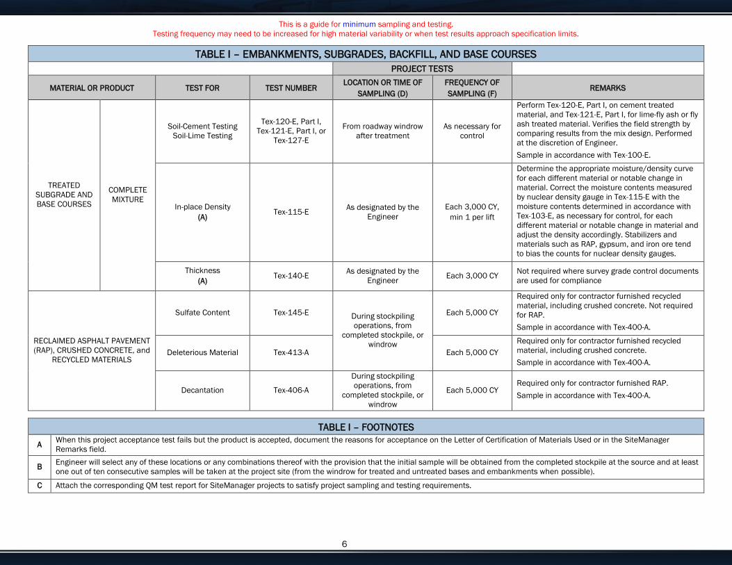
This is a guide for minimum sampling and testing.
Testing frequency may need to be increased for high material variability or when test results approach specification limits.
Enter customize text here for your needs or delete if not needed. 6
TABLE I – EMBANKMENTS, SUBGRADES, BACKFILL, AND BASE COURSES
PROJECT TESTS
MATERIAL OR PRODUCT TEST FOR TEST NUMBER LOCATION OR TIME OF
SAMPLING (D)
FREQUENCY OF
SAMPLING (F) REMARKS
TREATED
SUBGRADE AND
BASE COURSES
COMPLETE
MIXTURE
Soil-Cement Testing
Soil-Lime Testing
Tex-120-E, Part I,
Tex-121-E, Part I, or
Tex-127-E
From roadway windrow
after treatment
As necessary for
control
Perform Tex-120-E, Part I, on cement treated
material, and Tex-121-E, Part I, for lime-fly ash or fly
ash treated material. Verifies the field strength by
comparing results from the mix design. Performed
at the discretion of Engineer.
Sample in accordance with Tex-100-E.
In-place Density
(A) Tex-115-E
As designated by the
Engineer
Each 3,000 CY,
min 1 per lift
Determine the appropriate moisture/density curve
for each different material or notable change in
material. Correct the moisture contents measured
by nuclear density gauge in Tex-115-E with the
moisture contents determined in accordance with
Tex-103-E, as necessary for control, for each
different material or notable change in material and
adjust the density accordingly. Stabilizers and
materials such as RAP, gypsum, and iron ore tend
to bias the counts for nuclear density gauges.
Thickness
(A) Tex-140-E
As designated by the
Engineer Each 3,000 CY
Not required where survey grade control documents
are used for compliance
RECLAIMED ASPHALT PAVEMENT
(RAP), CRUSHED CONCRETE, and
RECYCLED MATERIALS
Sulfate Content Tex-145-E During stockpiling
operations, from
completed stockpile, or
windrow
Each 5,000 CY
Required only for contractor furnished recycled
material, including crushed concrete. Not required
for RAP.
Sample in accordance with Tex-400-A.
Deleterious Material Tex-413-A Each 5,000 CY
Required only for contractor furnished recycled
material, including crushed concrete.
Sample in accordance with Tex-400-A.
Decantation Tex-406-A
During stockpiling
operations, from
completed stockpile, or
windrow
Each 5,000 CY Required only for contractor furnished RAP.
Sample in accordance with Tex-400-A.
TABLE I – FOOTNOTES
A When this project acceptance test fails but the product is accepted, document the reasons for acceptance on the Letter of Certification of Materials Used or in the SiteManager
Remarks field.
B Engineer will select any of these locations or any combinations thereof with the provision that the initial sample will be obtained from the completed stockpile at the source and at least
one out of ten consecutive samples will be taken at the project site (from the windrow for treated and untreated bases and embankments when possible).
C Attach the corresponding QM test report for SiteManager projects to satisfy project sampling and testing requirements.

This is a guide for minimum sampling and testing.
Testing frequency may need to be increased for high material variability or when test results approach specification limits.
Enter customize text here for your needs or delete if not needed. 7
D
For acceptance testing, especially that which directly determines payment for the Contractor, sampling personnel should provide randomness in sampling by avoiding patterned
sampling routines. Examples of such sampling practices are as follows:
Soils/Flexible Base: For gradation, liquid limit, and plastic limit, vary sampling between stockpiling operations, completed stockpile, windrow, and project site. Vary the time of
day sampling is performed.
Aggregates: Sample aggregates nearest the point of incorporation into the work. Vary sampling between stockpiling operations, completed stockpile, belt sampling, and if
deemed necessary, railroad cars/trucks. Vary the time of day sampling is performed.
E The Engineer will sample from the completed stockpile at the source and test prior to placement.
F Each test performed that is based on a quantity of material is considered “or fraction thereof” for calculating number of tests.
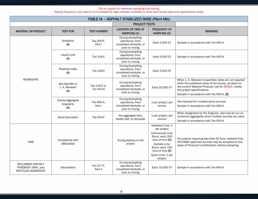
This is a guide for minimum sampling and testing.
Testing frequency may need to be increased for high material variability or when test results approach specification limits.
Enter customize text here for your needs or delete if not needed. 8
TABLE IA – ASPHALT STABILIZED BASE (Plant Mix)
PROJECT TESTS
MATERIAL OR PRODUCT TEST FOR TEST NUMBER LOCATION OR TIME OF
SAMPLING (C)
FREQUENCY OF
SAMPLING (D) REMARKS
AGGREGATE
Gradation
(A)
Tex-200-F,
Part I
During stockpiling
operations, from
completed stockpile, or
prior to mixing
Each 5,000 CY Sample in accordance with Tex-400-A.
Liquid Limit
(A) Tex-104-E
During stockpiling
operations, from
completed stockpile, or
prior to mixing
Each 5,000 CY Sample in accordance with Tex-400-A.
Plasticity Index
(A) Tex-106-E
During stockpiling
operations, from
completed stockpile, or
prior to mixing
Each 5,000 CY
Wet Ball Mill or
L. A. Abrasion
(A)
Tex-116-E or
Tex-410-A
During stockpiling
operations, from
completed stockpile, or
prior to mixing
Each 20,000 CY
When L. A. Abrasion is specified, tests are not required
when the published value of the source, as listed on
the current Material Producer List for BRSQC, meets
the project specifications.
Sample in accordance with Tex-400-A. (B)
Coarse Aggregate
Angularity
(A)
Tex-460-A,
Part I
During stockpiling
operations, from
completed stockpile, or
prior to mixing
1 per project, per
source
Not required for crushed stone sources.
Sample in accordance with Tex-400-A.
Sand Equivalent Tex-203-F Hot aggregate bins,
feeder belt, or stockpile
1 per project, per
source
When designated by the Engineer, test may be run on
combined aggregates when multiple sources are used.
Sample in accordance with Tex-400-A.
LIME Compliance with
DMS-6350
During delivery to the
project
Hydrated Lime: 1
per project
Commercial Lime
Slurry: each 200
tons of lime (D)
Carbide Lime
Slurry: each 100
tons of lime (D)
Quick Lime: 1 per
project
On projects requiring less than 50 tons, material from
CST/M&P approved sources may be accepted on the
basis of Producer’s Certification without sampling.
RECLAIMED ASPHALT
PAVEMENT (RAP), and
RECYCLED AGGREGATE
Decantation Tex-217-F,
Part II
During stockpiling
operations, from
completed stockpile, or
prior to mixing
Each 10,000 CY Sample in accordance with Tex-400-A.
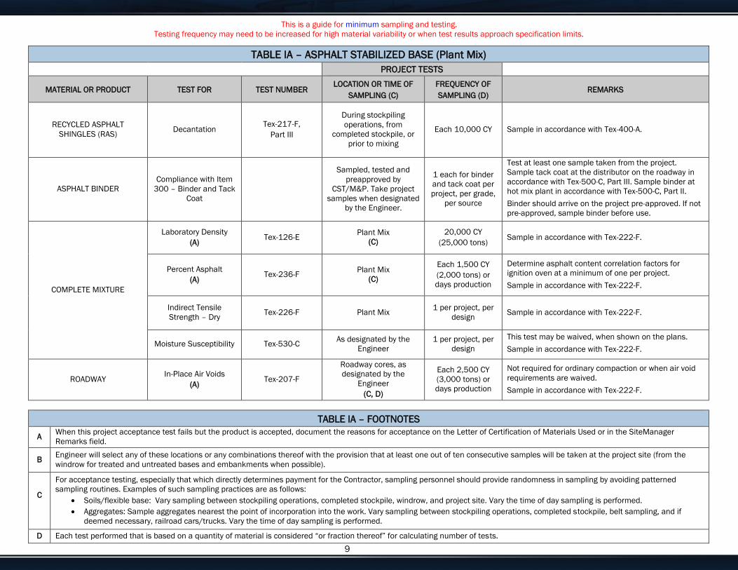
This is a guide for minimum sampling and testing.
Testing frequency may need to be increased for high material variability or when test results approach specification limits.
Enter customize text here for your needs or delete if not needed. 9
TABLE IA – ASPHALT STABILIZED BASE (Plant Mix)
PROJECT TESTS
MATERIAL OR PRODUCT TEST FOR TEST NUMBER LOCATION OR TIME OF
SAMPLING (C)
FREQUENCY OF
SAMPLING (D) REMARKS
RECYCLED ASPHALT
SHINGLES (RAS) Decantation
Tex-217-F,
Part III
During stockpiling
operations, from
completed stockpile, or
prior to mixing
Each 10,000 CY Sample in accordance with Tex-400-A.
ASPHALT BINDER
Compliance with Item
300 – Binder and Tack
Coat
Sampled, tested and
preapproved by
CST/M&P. Take project
samples when designated
by the Engineer.
1 each for binder
and tack coat per
project, per grade,
per source
Test at least one sample taken from the project.
Sample tack coat at the distributor on the roadway in
accordance with Tex-500-C, Part III. Sample binder at
hot mix plant in accordance with Tex-500-C, Part II.
Binder should arrive on the project pre-approved. If not
pre-approved, sample binder before use.
COMPLETE MIXTURE
Laboratory Density
(A) Tex-126-E
Plant Mix
(C)
20,000 CY
(25,000 tons) Sample in accordance with Tex-222-F.
Percent Asphalt
(A) Tex-236-F
Plant Mix
(C)
Each 1,500 CY
(2,000 tons) or
days production
Determine asphalt content correlation factors for
ignition oven at a minimum of one per project.
Sample in accordance with Tex-222-F.
Indirect Tensile
Strength – Dry Tex-226-F Plant Mix
1 per project, per
design Sample in accordance with Tex-222-F.
Moisture Susceptibility Tex-530-C As designated by the
Engineer
1 per project, per
design
This test may be waived, when shown on the plans.
Sample in accordance with Tex-222-F.
ROADWAY In-Place Air Voids
(A) Tex-207-F
Roadway cores, as
designated by the
Engineer
(C, D)
Each 2,500 CY
(3,000 tons) or
days production
Not required for ordinary compaction or when air void
requirements are waived.
Sample in accordance with Tex-222-F.
TABLE IA – FOOTNOTES
A When this project acceptance test fails but the product is accepted, document the reasons for acceptance on the Letter of Certification of Materials Used or in the SiteManager
Remarks field.
B Engineer will select any of these locations or any combinations thereof with the provision that at least one out of ten consecutive samples will be taken at the project site (from the
windrow for treated and untreated bases and embankments when possible).
C
For acceptance testing, especially that which directly determines payment for the Contractor, sampling personnel should provide randomness in sampling by avoiding patterned
sampling routines. Examples of such sampling practices are as follows:
Soils/flexible base: Vary sampling between stockpiling operations, completed stockpile, windrow, and project site. Vary the time of day sampling is performed.
Aggregates: Sample aggregates nearest the point of incorporation into the work. Vary sampling between stockpiling operations, completed stockpile, belt sampling, and if
deemed necessary, railroad cars/trucks. Vary the time of day sampling is performed.
D Each test performed that is based on a quantity of material is considered “or fraction thereof” for calculating number of tests.

This is a guide for minimum sampling and testing.
Testing frequency may need to be increased for high material variability or when test results approach specification limits.
Enter customize text here for your needs or delete if not needed. 10
TABLE II – SEAL COAT
PROJECT TESTS
MATERIAL OR PRODUCT TEST FOR TEST NUMBER LOCATION OR TIME OF
SAMPLING (C)
FREQUENCY OF
SAMPLING (D) REMARKS
AGGREGATE
Gradation
(A) Tex-200-F, Part I
Stockpile (At source or at
point of delivery)
One each 1,000 CY
Rate may be reduced to one each 2,000 CY if the
Engineer approves a contractor quality control plan.
Sample in accordance with Tex-221-F.
L. A. Abrasion
(A) Tex-410-A Stockpile 1 per 20,000 CY
Verify the published value of the source, as listed on
the current Material Producer List for BRSQC, meets
the project specifications. If not, sample and test at 1
per 20,000 CY prior to use.
Sample in accordance with Tex-221-F. (B)
Magnesium Soundness
(A) Tex-411-A Stockpile 1 per 20,000 CY
Verify the published value of the source, as listed on
the current Material Producer List for BRSQC, meets
the project specifications. If not, sample and test at 1
per 20,000 CY prior to use.
Sample in accordance with Tex-221-F. (B)
Surface Aggregate
Classification
(A)
Tex-612-J,
Tex-411-A Stockpile 1 per 20,000 CY
Verify the published value of the source, as listed on
the current Material Producer List for BRSQC, meets
the project specifications. If not, sample and test at 1
per 20,000 CY prior to use.
Sample in accordance with Tex-221-F. (B)
Pressure Slake
(A) Tex-431-A Stockpile 1 per 20,000 CY
Same as above. Required only for lightweight
aggregate.
Sample in accordance with Tex-221-F.
Freeze Thaw
(A) Tex-432-A Stockpile 1 per 20,000 CY
Same as above. Required only for lightweight
aggregate.
Sample in accordance with Tex-221-F.
Unit Weight Tex-404-A Stockpile 1 per 20,000 CY
Same as above. Required only for lightweight
aggregate.
Sample in accordance with Tex-221-F.
24 hr Water Absorption
(A) Tex-433-A Stockpile 1 per 20,000 CY
Same as above. Required only for lightweight
aggregate.
Sample in accordance with Tex-221-F.
Coarse Aggregate
Angularity Tex-460-A Stockpile 1 per 20,000 CY
Only required for crushed gravel.
Sample in accordance with Tex-221-F.
Deleterious Material
(A)
Tex-217-F,
Part I Stockpile 1 per 10,000 CY
Not required for lightweight aggregate.
Sample in accordance with Tex-221-F.
Decantation
(A) Tex-406-A Stockpile 1 per 10,000 CY Sample in accordance with Tex-221-F.
Flakiness Index Tex-224-F Stockpile
Frequency as
directed by the
Engineer
Sample in accordance with Tex-221-F.

This is a guide for minimum sampling and testing.
Testing frequency may need to be increased for high material variability or when test results approach specification limits.
Enter customize text here for your needs or delete if not needed. 11
TABLE IA – ASPHALT STABILIZED BASE (Plant Mix)
PROJECT TESTS
MATERIAL OR PRODUCT TEST FOR TEST NUMBER LOCATION OR TIME OF
SAMPLING (C)
FREQUENCY OF
SAMPLING (D) REMARKS
Micro Deval Tex-461-A Stockpile
1 per project or as
necessary for
control
Compare result to published value listed on the current
Material Producer List for BRSQC. Submit sample to
CST/M&P for Soundness and L.A. Abrasion testing
when results differ by more than 3% points, unless
otherwise directed by the Engineer. Sample in
accordance with Tex-221-F.
White Rock Count Tex-220-F Stockpile
Required only for Limestone Rock Asphalt. Not
required when CST/M&P provides inspection at the
plant. Sample in accordance with Tex-221-F.
Naturally Impregnated
Bitumen Content Tex-236-F Stockpile
Required only for Limestone Rock Asphalt. Not
required when CST/M&P provides inspection at the
plant. Sample in accordance with Tex-221-F.
PRECOATED AGGREGATE Asphalt Content Tex-236-F Stockpile
Frequency as
directed by the
Engineer when a
target value is
specified
Sample in accordance with Tex-221-F.
ASPHALT Compliance with
Item 300
Sampled, tested, and
preapproved by
CST/M&P. Take project
samples when
designated by the
Engineer from the
distributor or transport.
1 per project, per
grade, per source
Sample in accordance with Tex-500-C. Binder should
arrive on the project pre-approved. If not pre-approved,
sample binder before use.
TABLE II – FOOTNOTES
A When this project acceptance test fails but the product is accepted, document the reasons for acceptance on the Letter of Certification of Materials Used or in the SiteManager
Remarks field.
B Attach the corresponding QM test report for SiteManager projects to satisfy project sampling and testing requirements.
C
For acceptance testing, especially that which directly determines payment for the Contractor, sampling personnel should provide randomness in sampling by avoiding patterned
sampling routines. Examples of such sampling practices are as follows:
Aggregates: Sample aggregates nearest the point of incorporation into the work. Vary sampling between stockpiling operations, completed stockpile, belt sampling, and if
deemed necessary, railroad cars/trucks. Vary the time of day sampling is performed.
D Each test performed that is based on a quantity of material is considered “or fraction thereof” for calculating number of tests.
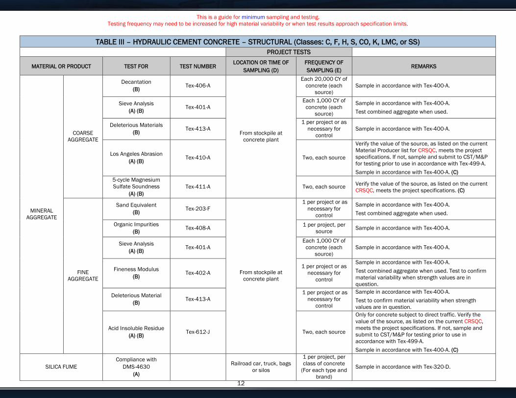
This is a guide for minimum sampling and testing.
Testing frequency may need to be increased for high material variability or when test results approach specification limits.
Enter customize text here for your needs or delete if not needed. 12
TABLE III – HYDRAULIC CEMENT CONCRETE – STRUCTURAL (Classes: C, F, H, S, CO, K, LMC, or SS)
PROJECT TESTS
MATERIAL OR PRODUCT TEST FOR TEST NUMBER LOCATION OR TIME OF
SAMPLING (D)
FREQUENCY OF
SAMPLING (E) REMARKS
MINERAL
AGGREGATE
COARSE
AGGREGATE
Decantation
(B) Tex-406-A
From stockpile at
concrete plant
Each 20,000 CY of
concrete (each
source)
Sample in accordance with Tex-400-A.
Sieve Analysis
(A) (B) Tex-401-A
Each 1,000 CY of
concrete (each
source)
Sample in accordance with Tex-400-A.
Test combined aggregate when used.
Deleterious Materials
(B) Tex-413-A
1 per project or as
necessary for
control
Sample in accordance with Tex-400-A.
Los Angeles Abrasion
(A) (B) Tex-410-A Two, each source
Verify the value of the source, as listed on the current
Material Producer list for CRSQC, meets the project
specifications. If not, sample and submit to CST/M&P
for testing prior to use in accordance with Tex-499-A.
Sample in accordance with Tex-400-A. (C)
5-cycle Magnesium
Sulfate Soundness
(A) (B)
Tex-411-A Two, each source Verify the value of the source, as listed on the current
CRSQC, meets the project specifications. (C)
FINE
AGGREGATE
Sand Equivalent
(B) Tex-203-F
From stockpile at
concrete plant
1 per project or as
necessary for
control
Sample in accordance with Tex-400-A.
Test combined aggregate when used.
Organic Impurities
(B) Tex-408-A
1 per project, per
source Sample in accordance with Tex-400-A.
Sieve Analysis
(A) (B) Tex-401-A
Each 1,000 CY of
concrete (each
source)
Sample in accordance with Tex-400-A.
Fineness Modulus
(B) Tex-402-A
1 per project or as
necessary for
control
Sample in accordance with Tex-400-A.
Test combined aggregate when used. Test to confirm
material variability when strength values are in
question.
Deleterious Material
(B) Tex-413-A
1 per project or as
necessary for
control
Sample in accordance with Tex-400-A.
Test to confirm material variability when strength
values are in question.
Acid Insoluble Residue
(A) (B) Tex-612-J Two, each source
Only for concrete subject to direct traffic. Verify the
value of the source, as listed on the current CRSQC,
meets the project specifications. If not, sample and
submit to CST/M&P for testing prior to use in
accordance with Tex-499-A.
Sample in accordance with Tex-400-A. (C)
SILICA FUME
Compliance with
DMS-4630
(A)
Railroad car, truck, bags
or silos
1 per project, per
class of concrete
(For each type and
brand)
Sample in accordance with Tex-320-D.
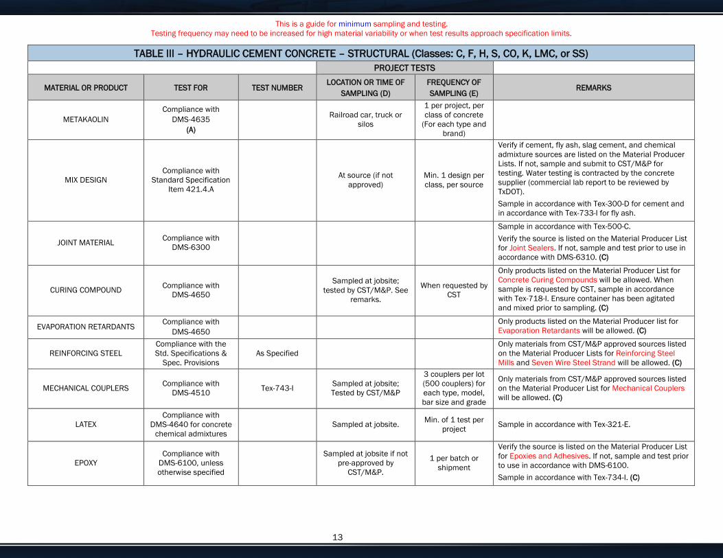
This is a guide for minimum sampling and testing.
Testing frequency may need to be increased for high material variability or when test results approach specification limits.
Enter customize text here for your needs or delete if not needed. 13
TABLE III – HYDRAULIC CEMENT CONCRETE – STRUCTURAL (Classes: C, F, H, S, CO, K, LMC, or SS)
PROJECT TESTS
MATERIAL OR PRODUCT TEST FOR TEST NUMBER LOCATION OR TIME OF
SAMPLING (D)
FREQUENCY OF
SAMPLING (E) REMARKS
METAKAOLIN
Compliance with
DMS-4635
(A)
Railroad car, truck or
silos
1 per project, per
class of concrete
(For each type and
brand)
MIX DESIGN
Compliance with
Standard Specification
Item 421.4.A
At source (if not
approved)
Min. 1 design per
class, per source
Verify if cement, fly ash, slag cement, and chemical
admixture sources are listed on the Material Producer
Lists. If not, sample and submit to CST/M&P for
testing. Water testing is contracted by the concrete
supplier (commercial lab report to be reviewed by
TxDOT).
Sample in accordance with Tex-300-D for cement and
in accordance with Tex-733-I for fly ash.
JOINT MATERIAL Compliance with
DMS-6300
Sample in accordance with Tex-500-C.
Verify the source is listed on the Material Producer List
for Joint Sealers. If not, sample and test prior to use in
accordance with DMS-6310. (C)
CURING COMPOUND Compliance with
DMS-4650
Sampled at jobsite;
tested by CST/M&P. See
remarks.
When requested by
CST
Only products listed on the Material Producer List for
Concrete Curing Compounds will be allowed. When
sample is requested by CST, sample in accordance
with Tex-718-I. Ensure container has been agitated
and mixed prior to sampling. (C)
EVAPORATION RETARDANTS Compliance with
DMS-4650
Only products listed on the Material Producer list for
Evaporation Retardants will be allowed. (C)
REINFORCING STEEL
Compliance with the
Std. Specifications &
Spec. Provisions
As Specified
Only materials from CST/M&P approved sources listed
on the Material Producer Lists for Reinforcing Steel
Mills and Seven Wire Steel Strand will be allowed. (C)
MECHANICAL COUPLERS Compliance with
DMS-4510 Tex-743-I
Sampled at jobsite;
Tested by CST/M&P
3 couplers per lot
(500 couplers) for
each type, model,
bar size and grade
Only materials from CST/M&P approved sources listed
on the Material Producer List for Mechanical Couplers
will be allowed. (C)
LATEX
Compliance with
DMS-4640 for concrete
chemical admixtures
Sampled at jobsite. Min. of 1 test per
project Sample in accordance with Tex-321-E.
EPOXY
Compliance with
DMS-6100, unless
otherwise specified
Sampled at jobsite if not
pre-approved by
CST/M&P.
1 per batch or
shipment
Verify the source is listed on the Material Producer List
for Epoxies and Adhesives. If not, sample and test prior
to use in accordance with DMS-6100.
Sample in accordance with Tex-734-I. (C)
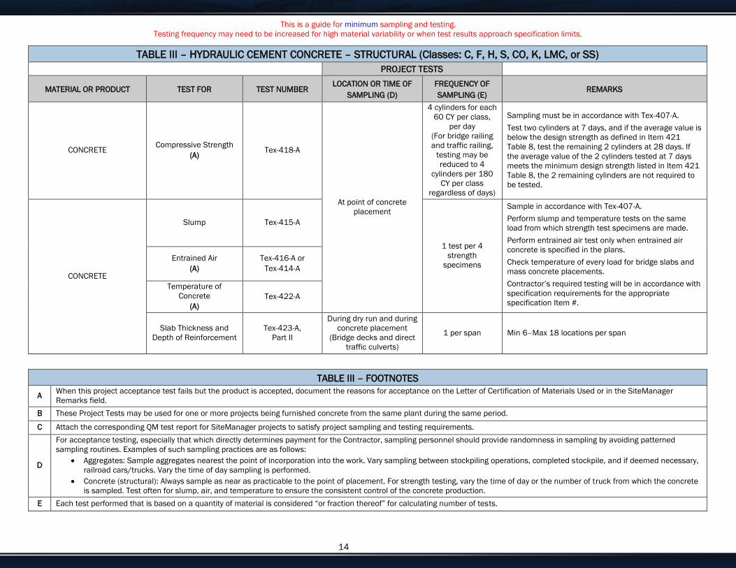
This is a guide for minimum sampling and testing.
Testing frequency may need to be increased for high material variability or when test results approach specification limits.
Enter customize text here for your needs or delete if not needed. 14
TABLE III – HYDRAULIC CEMENT CONCRETE – STRUCTURAL (Classes: C, F, H, S, CO, K, LMC, or SS)
PROJECT TESTS
MATERIAL OR PRODUCT TEST FOR TEST NUMBER LOCATION OR TIME OF
SAMPLING (D)
FREQUENCY OF
SAMPLING (E) REMARKS
CONCRETE Compressive Strength
(A) Tex-418-A
At point of concrete
placement
4 cylinders for each
60 CY per class,
per day
(For bridge railing
and traffic railing,
testing may be
reduced to 4
cylinders per 180
CY per class
regardless of days)
Sampling must be in accordance with Tex-407-A.
Test two cylinders at 7 days, and if the average value is
below the design strength as defined in Item 421
Table 8, test the remaining 2 cylinders at 28 days. If
the average value of the 2 cylinders tested at 7 days
meets the minimum design strength listed in Item 421
Table 8, the 2 remaining cylinders are not required to
be tested.
CONCRETE
Slump Tex-415-A
1 test per 4
strength
specimens
Sample in accordance with Tex-407-A.
Perform slump and temperature tests on the same
load from which strength test specimens are made.
Perform entrained air test only when entrained air
concrete is specified in the plans.
Check temperature of every load for bridge slabs and
mass concrete placements.
Contractor’s required testing will be in accordance with
specification requirements for the appropriate
specification Item #.
Entrained Air
(A)
Tex-416-A or
Tex-414-A
Temperature of
Concrete
(A)
Tex-422-A
Slab Thickness and
Depth of Reinforcement
Tex-423-A,
Part II
During dry run and during
concrete placement
(Bridge decks and direct
traffic culverts)
1 per span Min 6–Max 18 locations per span
TABLE III – FOOTNOTES
A When this project acceptance test fails but the product is accepted, document the reasons for acceptance on the Letter of Certification of Materials Used or in the SiteManager
Remarks field.
B These Project Tests may be used for one or more projects being furnished concrete from the same plant during the same period.
C Attach the corresponding QM test report for SiteManager projects to satisfy project sampling and testing requirements.
D
For acceptance testing, especially that which directly determines payment for the Contractor, sampling personnel should provide randomness in sampling by avoiding patterned
sampling routines. Examples of such sampling practices are as follows:
Aggregates: Sample aggregates nearest the point of incorporation into the work. Vary sampling between stockpiling operations, completed stockpile, and if deemed necessary,
railroad cars/trucks. Vary the time of day sampling is performed.
Concrete (structural): Always sample as near as practicable to the point of placement. For strength testing, vary the time of day or the number of truck from which the concrete
is sampled. Test often for slump, air, and temperature to ensure the consistent control of the concrete production.
E Each test performed that is based on a quantity of material is considered “or fraction thereof” for calculating number of tests.
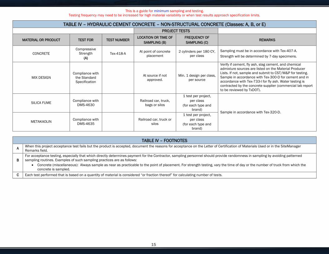
This is a guide for minimum sampling and testing.
Testing frequency may need to be increased for high material variability or when test results approach specification limits.
Enter customize text here for your needs or delete if not needed. 15
TABLE IV – HYDRAULIC CEMENT CONCRETE – NON-STRUCTURAL CONCRETE (Classes: A, B, or E)
PROJECT TESTS
MATERIAL OR PRODUCT TEST FOR TEST NUMBER LOCATION OR TIME OF
SAMPLING (B)
FREQUENCY OF
SAMPLING (C) REMARKS
CONCRETE
Compressive
Strength
(A)
Tex-418-A At point of concrete
placement
2 cylinders per 180 CY,
per class
Sampling must be in accordance with Tex-407-A.
Strength will be determined by 7-day specimens.
MIX DESIGN
Compliance with
the Standard
Specification
At source if not
approved.
Min. 1 design per class,
per source
Verify if cement, fly ash, slag cement, and chemical
admixture sources are listed on the Material Producer
Lists. If not, sample and submit to CST/M&P for testing.
Sample in accordance with Tex-300-D for cement and in
accordance with Tex-733-I for fly ash. Water testing is
contracted by the concrete supplier (commercial lab report
to be reviewed by TxDOT).
SILICA FUME Compliance with
DMS-4630
Railroad car, truck,
bags or silos
1 test per project,
per class
(for each type and
brand) Sample in accordance with Tex-320-D.
METAKAOLIN Compliance with
DMS-4635
Railroad car, truck or
silos
1 test per project,
per class
(for each type and
brand)
TABLE IV – FOOTNOTES
A When this project acceptance test fails but the product is accepted, document the reasons for acceptance on the Letter of Certification of Materials Used or in the SiteManager
Remarks field.
B
For acceptance testing, especially that which directly determines payment for the Contractor, sampling personnel should provide randomness in sampling by avoiding patterned
sampling routines. Examples of such sampling practices are as follows:
Concrete (miscellaneous): Always sample as near as practicable to the point of placement. For strength testing, vary the time of day or the number of truck from which the
concrete is sampled.
C Each test performed that is based on a quantity of material is considered “or fraction thereof” for calculating number of tests.
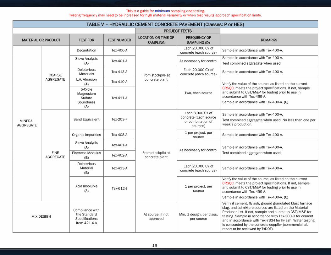
This is a guide for minimum sampling and testing.
Testing frequency may need to be increased for high material variability or when test results approach specification limits.
Enter customize text here for your needs or delete if not needed. 16
TABLE V – HYDRAULIC CEMENT CONCRETE PAVEMENT (Classes: P or HES)
PROJECT TESTS
MATERIAL OR PRODUCT TEST FOR TEST NUMBER LOCATION OR TIME OF
SAMPLING
FREQUENCY OF
SAMPLING (D) REMARKS
MINERAL
AGGREGATE
COARSE
AGGREGATE
Decantation Tex-406-A
From stockpile at
concrete plant
Each 20,000 CY of
concrete (each source) Sample in accordance with Tex-400-A.
Sieve Analysis
(A) Tex-401-A As necessary for control
Sample in accordance with Tex-400-A.
Test combined aggregate when used.
Deleterious
Materials Tex-413-A
Each 20,000 CY of
concrete (each source) Sample in accordance with Tex-400-A.
L.A. Abrasion
(A) Tex-410-A
Two, each source
Verify the value of the source, as listed on the current
CRSQC, meets the project specifications. If not, sample
and submit to CST/M&P for testing prior to use in
accordance with Tex-499-A.
Sample in accordance with Tex-400-A. (C)
5-Cycle
Magnesium
Sulfate
Soundness
(A)
Tex-411-A
FINE
AGGREGATE
Sand Equivalent Tex-203-F
From stockpile at
concrete plant
Each 3,000 CY of
concrete (Each source
or combination of
sources)
Sample in accordance with Tex-400-A.
Test combined aggregate when used. No less than one per
week’s production.
Organic Impurities Tex-408-A 1 per project, per
source Sample in accordance with Tex-400-A.
Sieve Analysis
(A) Tex-401-A
As necessary for control Sample in accordance with Tex-400-A.
Test combined aggregate when used. Fineness Modulus
(B) Tex-402-A
Deleterious
Material
(B)
Tex-413-A Each 20,000 CY of
concrete (each source) Sample in accordance with Tex-400-A.
Acid Insoluble
(A) Tex-612-J
1 per project, per
source
Verify the value of the source, as listed on the current
CRSQC, meets the project specifications. If not, sample
and submit to CST/M&P for testing prior to use in
accordance with Tex-499-A.
Sample in accordance with Tex-400-A. (C)
MIX DESIGN
Compliance with
the Standard
Specifications
Item 421.4.A
At source, if not
approved
Min. 1 design, per class,
per source
Verify if cement, fly ash, ground granulated blast furnace
slag, and admixture sources are listed on the Material
Producer List. If not, sample and submit to CST/M&P for
testing. Sample in accordance with Tex-300-D for cement
and in accordance with Tex-733-I for fly ash. Water testing
is contracted by the concrete supplier (commercial lab
report to be reviewed by TxDOT).
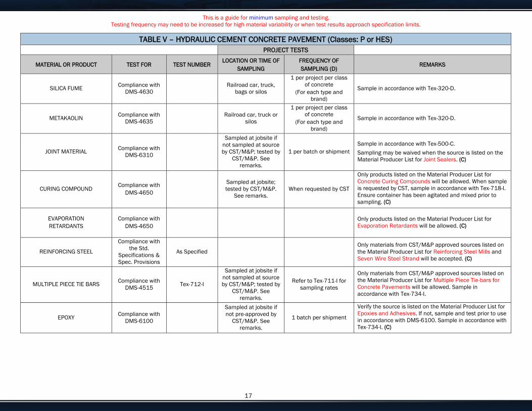
This is a guide for minimum sampling and testing.
Testing frequency may need to be increased for high material variability or when test results approach specification limits.
Enter customize text here for your needs or delete if not needed. 17
TABLE V – HYDRAULIC CEMENT CONCRETE PAVEMENT (Classes: P or HES)
PROJECT TESTS
MATERIAL OR PRODUCT TEST FOR TEST NUMBER LOCATION OR TIME OF
SAMPLING
FREQUENCY OF
SAMPLING (D) REMARKS
SILICA FUME Compliance with
DMS-4630
Railroad car, truck,
bags or silos
1 per project per class
of concrete
(For each type and
brand)
Sample in accordance with Tex-320-D.
METAKAOLIN Compliance with
DMS-4635
Railroad car, truck or
silos
1 per project per class
of concrete
(For each type and
brand)
Sample in accordance with Tex-320-D.
JOINT MATERIAL Compliance with
DMS-6310
Sampled at jobsite if
not sampled at source
by CST/M&P; tested by
CST/M&P. See
remarks.
1 per batch or shipment
Sample in accordance with Tex-500-C.
Sampling may be waived when the source is listed on the
Material Producer List for Joint Sealers. (C)
CURING COMPOUND Compliance with
DMS-4650
Sampled at jobsite;
tested by CST/M&P.
See remarks.
When requested by CST
Only products listed on the Material Producer List for
Concrete Curing Compounds will be allowed. When sample
is requested by CST, sample in accordance with Tex-718-I.
Ensure container has been agitated and mixed prior to
sampling. (C)
EVAPORATION
RETARDANTS
Compliance with
DMS-4650
Only products listed on the Material Producer List for
Evaporation Retardants will be allowed. (C)
REINFORCING STEEL
Compliance with
the Std.
Specifications &
Spec. Provisions
As Specified
Only materials from CST/M&P approved sources listed on
the Material Producer List for Reinforcing Steel Mills and
Seven Wire Steel Strand will be accepted. (C)
MULTIPLE PIECE TIE BARS Compliance with
DMS-4515 Tex-712-I
Sampled at jobsite if
not sampled at source
by CST/M&P; tested by
CST/M&P. See
remarks.
Refer to Tex-711-I for
sampling rates
Only materials from CST/M&P approved sources listed on
the Material Producer List for Multiple Piece Tie-bars for
Concrete Pavements will be allowed. Sample in
accordance with Tex-734-I.
EPOXY Compliance with
DMS-6100
Sampled at jobsite if
not pre-approved by
CST/M&P. See
remarks.
1 batch per shipment
Verify the source is listed on the Material Producer List for
Epoxies and Adhesives. If not, sample and test prior to use
in accordance with DMS-6100. Sample in accordance with
Tex-734-I. (C)
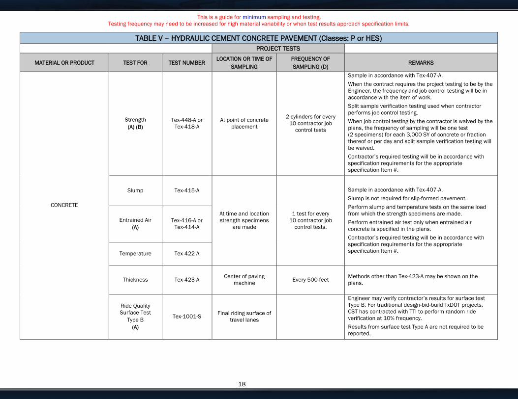
This is a guide for minimum sampling and testing.
Testing frequency may need to be increased for high material variability or when test results approach specification limits.
Enter customize text here for your needs or delete if not needed. 18
TABLE V – HYDRAULIC CEMENT CONCRETE PAVEMENT (Classes: P or HES)
PROJECT TESTS
MATERIAL OR PRODUCT TEST FOR TEST NUMBER LOCATION OR TIME OF
SAMPLING
FREQUENCY OF
SAMPLING (D) REMARKS
CONCRETE
Strength
(A) (B)
Tex-448-A or
Tex-418-A
At point of concrete
placement
2 cylinders for every
10 contractor job
control tests
Sample in accordance with Tex-407-A.
When the contract requires the project testing to be by the
Engineer, the frequency and job control testing will be in
accordance with the item of work.
Split sample verification testing used when contractor
performs job control testing.
When job control testing by the contractor is waived by the
plans, the frequency of sampling will be one test
(2 specimens) for each 3,000 SY of concrete or fraction
thereof or per day and split sample verification testing will
be waived.
Contractor’s required testing will be in accordance with
specification requirements for the appropriate
specification Item #.
Slump Tex-415-A
At time and location
strength specimens
are made
1 test for every
10 contractor job
control tests.
Sample in accordance with Tex-407-A.
Slump is not required for slip-formed pavement.
Perform slump and temperature tests on the same load
from which the strength specimens are made.
Perform entrained air test only when entrained air
concrete is specified in the plans.
Contractor’s required testing will be in accordance with
specification requirements for the appropriate
specification Item #.
Entrained Air
(A)
Tex-416-A or
Tex-414-A
Temperature Tex-422-A
Thickness Tex-423-A Center of paving
machine Every 500 feet
Methods other than Tex-423-A may be shown on the
plans.
Ride Quality
Surface Test
Type B
(A)
Tex-1001-S Final riding surface of
travel lanes
Engineer may verify contractor’s results for surface test
Type B. For traditional design-bid-build TxDOT projects,
CST has contracted with TTI to perform random ride
verification at 10% frequency.
Results from surface test Type A are not required to be
reported.

This is a guide for minimum sampling and testing.
Testing frequency may need to be increased for high material variability or when test results approach specification limits.
Enter customize text here for your needs or delete if not needed. 19
TABLE V – FOOTNOTES
A When this project acceptance test fails but the product is accepted, document the reasons for acceptance on the Letter of Certification of Materials Used or in the SiteManager
Remarks field.
B When a project test does not meet the specified strength requirements and a reduced pay factor is assigned, document the analysis on the Letter of Certification of Materials Used.
C Attach the corresponding QM test report for SiteManager projects to satisfy project sampling and testing requirements.
D Each test performed that is based on a quantity of material is considered “or fraction thereof” for calculating number of tests.
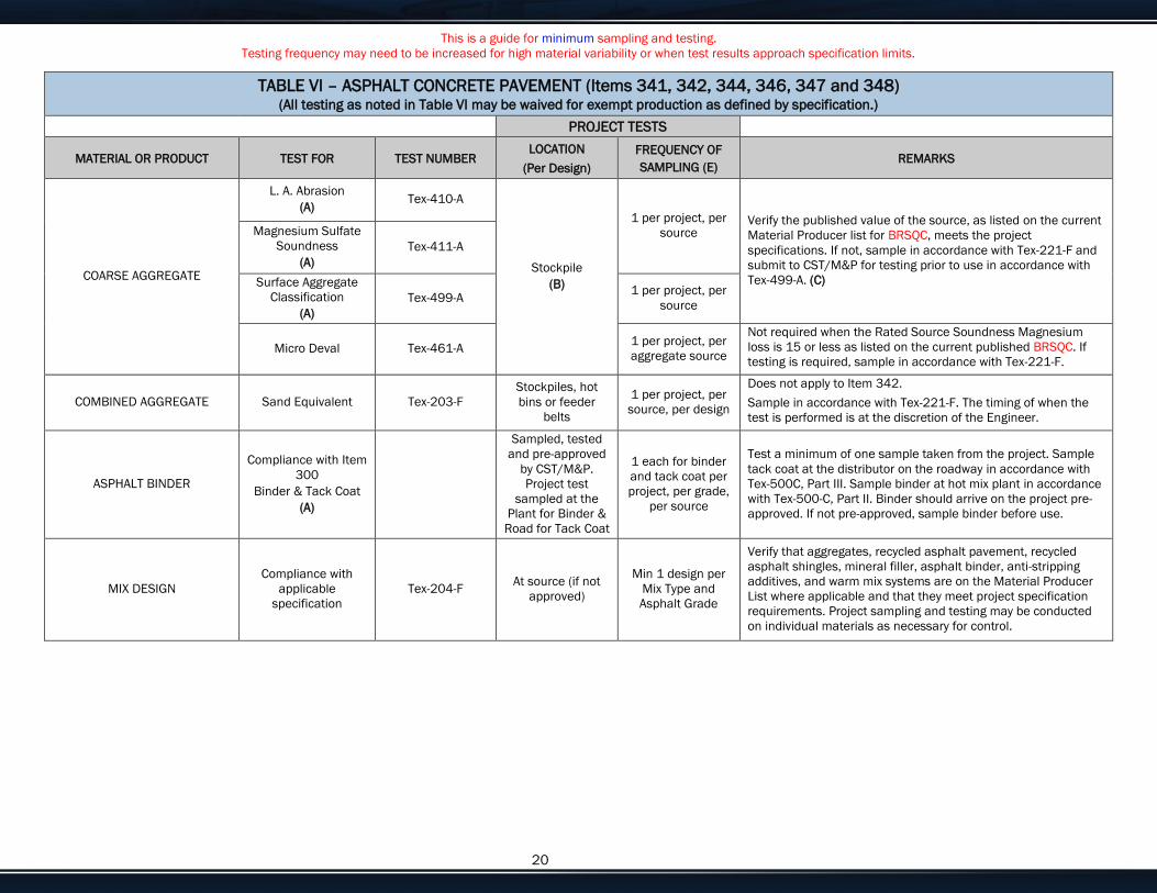
This is a guide for minimum sampling and testing.
Testing frequency may need to be increased for high material variability or when test results approach specification limits.
Enter customize text here for your needs or delete if not needed. 20
TABLE VI – ASPHALT CONCRETE PAVEMENT (Items 341, 342, 344, 346, 347 and 348) (All testing as noted in Table VI may be waived for exempt production as defined by specification.)
PROJECT TESTS
MATERIAL OR PRODUCT TEST FOR TEST NUMBER LOCATION
(Per Design)
FREQUENCY OF
SAMPLING (E) REMARKS
COARSE AGGREGATE
L. A. Abrasion
(A) Tex-410-A
Stockpile
(B)
1 per project, per
source Verify the published value of the source, as listed on the current
Material Producer list for BRSQC, meets the project
specifications. If not, sample in accordance with Tex-221-F and
submit to CST/M&P for testing prior to use in accordance with
Tex-499-A. (C)
Magnesium Sulfate
Soundness
(A)
Tex-411-A
Surface Aggregate
Classification
(A)
Tex-499-A 1 per project, per
source
Micro Deval Tex-461-A 1 per project, per
aggregate source
Not required when the Rated Source Soundness Magnesium
loss is 15 or less as listed on the current published BRSQC. If
testing is required, sample in accordance with Tex-221-F.
COMBINED AGGREGATE Sand Equivalent Tex-203-F
Stockpiles, hot
bins or feeder
belts
1 per project, per
source, per design
Does not apply to Item 342.
Sample in accordance with Tex-221-F. The timing of when the
test is performed is at the discretion of the Engineer.
ASPHALT BINDER
Compliance with Item
300
Binder & Tack Coat
(A)
Sampled, tested
and pre-approved
by CST/M&P.
Project test
sampled at the
Plant for Binder &
Road for Tack Coat
1 each for binder
and tack coat per
project, per grade,
per source
Test a minimum of one sample taken from the project. Sample
tack coat at the distributor on the roadway in accordance with
Tex-500C, Part III. Sample binder at hot mix plant in accordance
with Tex-500-C, Part II. Binder should arrive on the project pre-
approved. If not pre-approved, sample binder before use.
MIX DESIGN
Compliance with
applicable
specification
Tex-204-F At source (if not
approved)
Min 1 design per
Mix Type and
Asphalt Grade
Verify that aggregates, recycled asphalt pavement, recycled
asphalt shingles, mineral filler, asphalt binder, anti-stripping
additives, and warm mix systems are on the Material Producer
List where applicable and that they meet project specification
requirements. Project sampling and testing may be conducted
on individual materials as necessary for control.

This is a guide for minimum sampling and testing.
Testing frequency may need to be increased for high material variability or when test results approach specification limits.
Enter customize text here for your needs or delete if not needed. 21
TABLE VI – ASPHALT CONCRETE PAVEMENT (Items 341, 342, 344, 346, 347 and 348) (All testing as noted in Table VI may be waived for exempt production as defined by specification.)
PROJECT TESTS PROJECT INDEPENDENT
ASSURANCE TESTS
MATERIAL OR
PRODUCT TEST FOR
TEST
NUMBER LOCATION
FREQUENCY
(Per Design) LOCATION FREQUENCY REMARKS
COMPLETE
MIXTURE
Asphalt Content (%)
(A) Tex-236-F
Engineer Truck
Sample
(D)
Minimum 1 per Lot
Sample in accordance with Tex-222-F.
Determine correlation factors for ignition oven
using Tex-236-F at a minimum of one per
project.
Voids in Mineral
Aggregates (VMA) Tex-207-F
Truck Sample
Plant Produced
(D)
1 per Sublot Truck
1 per 10 Lots
only if
compactor is
shared by
Contractor and
State
Sample in accordance with Tex-222-F.
Does not apply to Item 342, “Permeable
Friction Course.”
Contractor’s required testing will be in
accordance with specification requirements for
the appropriate specification Item #.
Gradation
(A) Tex-236-F
Engineer Truck
Sample
(D)
Minimum 1 per 12
Sublots
(E)
Sample in accordance with Tex-222-F.
Determine correlation factors for ignition oven
using Tex-236-F at a minimum of one per
project.
Boil Test Tex-530-C Truck Sample
1 per project
Sample in accordance with Tex-222-F.
Unless waived by the Engineer.
Indirect Tensile
Strength – Dry Tex-226-F
Sample in accordance with Tex-222-F.
Unless waived by the Engineer.
Does not apply to Items 342, 346, and 348.
Moisture Content Tex-212-F,
Part II
Engineer Truck
Sample Sample in accordance with Tex-222-F.
Lab Molded Density
(A) Tex-207-F
Truck Sample
(D)
1 per Sublot
1 per Lot for Item
347
Truck
1 per 10 Lots
only if
compactor is
shared by
Contractor and
State
Sample in accordance with Tex-222-F.
Contractor’s required testing will be in
accordance with specification requirements for
the appropriate specification Item #.
Drain Down Test
(A) Tex-235-F
Engineer Truck
Sample
1 per project
1 per Lot for Item
342
Sample in accordance with Tex-222-F.
Not required for Item 341 and Item 344.
Hamburg Wheel Test
(A) Tex-242-F
Engineer Truck
Sample 1 per project
Sample in accordance with Tex-222-F. Sample
during production.
Does not apply to Item 348.
Overlay Test Tex-248-F Engineer Truck
Sample 1 per project
Sample in accordance with Tex-222-F.
Does not apply to Items 341, 344, and 348.
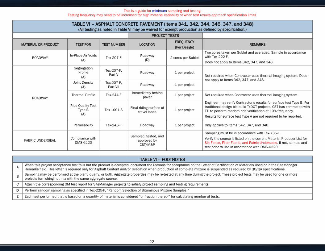
This is a guide for minimum sampling and testing.
Testing frequency may need to be increased for high material variability or when test results approach specification limits.
Enter customize text here for your needs or delete if not needed. 22
TABLE VI – ASPHALT CONCRETE PAVEMENT (Items 341, 342, 344, 346, 347, and 348) (All testing as noted in Table VI may be waived for exempt production as defined by specification.)
PROJECT TESTS
MATERIAL OR PRODUCT TEST FOR TEST NUMBER LOCATION FREQUENCY
(Per Design) REMARKS
ROADWAY In-Place Air Voids
(A) Tex-207-F
Roadway
(D) 2 cores per Sublot
Two cores taken per Sublot and averaged. Sample in accordance
with Tex-222-F.
Does not apply to Items 342, 347, and 348.
ROADWAY
Segregation
Profile
(A)
Tex-207-F,
Part V Roadway 1 per project
Not required when Contractor uses thermal imaging system. Does
not apply to Items 342, 347, and 348. Joint Density
(A)
Tex-207-F,
Part VII Roadway 1 per project
Thermal Profile Tex-244-F Immediately behind
paver 1 per project Not required when Contractor uses thermal imaging system.
Ride Quality Test
Type B
(A)
Tex-1001-S Final riding surface of
travel lanes 1 per project
Engineer may verify Contractor’s results for surface test Type B. For
traditional design-bid-build TxDOT projects, CST has contracted with
TTI to perform random ride verification at 10% frequency.
Results for surface test Type A are not required to be reported.
Permeability Tex-246-F Roadway 1 per project Only applies to Items 342, 347, and 348.
FABRIC UNDERSEAL Compliance with
DMS-6220
Sampled, tested, and
approved by
CST/M&P
Sampling must be in accordance with Tex-735-I.
Verify the source is listed on the current Material Producer List for
Silt Fence, Filter Fabric, and Fabric Underseals. If not, sample and
test prior to use in accordance with DMS-6220.
TABLE VI – FOOTNOTES
A When this project acceptance test fails but the product is accepted, document the reasons for acceptance on the Letter of Certification of Materials Used or in the SiteManager
Remarks field. This letter is required only for Asphalt Content and/or Gradation when production of complete mixture is suspended as required by QC/QA specifications.
B Sampling may be performed at the plant, quarry, or both. Aggregate properties may be re-tested at any time during the project. These project tests may be used for one or more
projects furnishing hot mix with the same aggregate source.
C Attach the corresponding QM test report for SiteManager projects to satisfy project sampling and testing requirements.
D Perform random sampling as specified in Tex-225-F, “Random Selection of Bituminous Mixture Samples.”
E Each test performed that is based on a quantity of material is considered “or fraction thereof” for calculating number of tests.
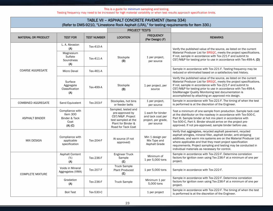
This is a guide for minimum sampling and testing.
Testing frequency may need to be increased for high material variability or when test results approach specification limits.
Enter customize text here for your needs or delete if not needed. 23
TABLE VII – ASPHALT CONCRETE PAVEMENT (Items 334) (Refer to DMS-9210, “Limestone Rock Asphalt (LRA),” for testing requirements for Item 330.)
PROJECT TESTS
MATERIAL OR PRODUCT TEST FOR TEST NUMBER LOCATION FREQUENCY
(Per Design) (F) REMARKS
COARSE AGGREGATE
L. A. Abrasion
(A) Tex-410-A
Stockpile
(B)
1 per project,
per source
Verify the published value of the source, as listed on the current
Material Producer List for BRSQC, meets the project specifications.
If not, sample in accordance with Tex-221-F and submit to
CST/M&P for testing prior to use in accordance with Tex-499-A. (D)
Magnesium
Sulfate
Soundness
(A)
Tex-411-A
Micro Deval Tex-461-A Sample in accordance with Tex-221-F. Testing frequency may be
reduced or eliminated based on a satisfactory test history.
Surface
Aggregate
Classification
(A)
Tex-499-A Stockpile
(B)
1 per project, per
source
Verify the published value of the source, as listed on the current
Material Producer List for BRSQC, meets the project specifications.
If not, sample in accordance with Tex-221-F and submit to
CST/M&P for testing prior to use in accordance with Tex-499-A.
SiteManager Quality Monitoring test documentation is
accomplished by attaching an approved mix design.
COMBINED AGGREGATE Sand Equivalent Tex-203-F Stockpiles, hot bins
or feeder belts
1 per project,
per source
Sample in accordance with Tex-221-F. The timing of when the test
is performed is at the discretion of the Engineer.
ASPHALT BINDER
Compliance with
Item 300
Binder & Tack
Coat
(A) (C)
Sampled, tested and
pre-approved by
CST/M&P. Project
test sampled at the
Plant for Binder &
Road for Tack Coat
1 each for binder
and tack coat per
project, per grade,
per source
Test a minimum of one sample from production. Sample tack coat
at the distributor on the roadway in accordance with Tex-500-C,
Part III. Sample binder at hot mix plant in accordance with
Tex-500-C, Part II. Binder should arrive on the project pre-
approved. If not pre-approved, sample binder before use.
MIX DESIGN
Compliance with
applicable
specification
Tex-204-F At source (if not
approved)
Min 1 design per
Mix Type and
Asphalt Grade
Verify that aggregates, recycled asphalt pavement, recycled
asphalt shingles, mineral filler, asphalt binder, anti-stripping
additives, and warm mix systems are on the Material Producer List
where applicable and that they meet project specification
requirements. Project sampling and testing may be conducted in
individual materials as necessary for control.
COMPLETE MIXTURE
Asphalt Content
(%)
(A)
Tex-236-F
Engineer Truck
Sample
(E)
Minimum of
1 per 5,000 tons
Sample in accordance with Tex-222-F. Determine correlation
factors for ignition oven using Tex-236-F at a minimum of one per
project.
Voids in Mineral
Aggregates (VMA) Tex-207-F
Truck Sample
Plant Produced
(E)
1 per 5,000 tons Sample in accordance with Tex-222-F.
Gradation
(A) Tex-236-F Truck Sample
Minimum 1 per
5,000 tons
Sample in accordance with Tex-222-F. Determine correlation
factors for ignition oven using Tex-236-F at a minimum of one per
project.
Boil Test Tex-530-C 1 per project Sample in accordance with Tex-222-F. The timing of when the test
is performed is at the discretion of the Engineer.
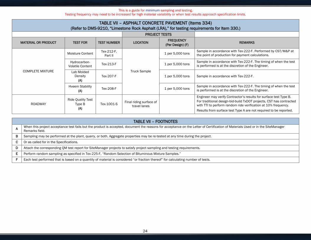
This is a guide for minimum sampling and testing.
Testing frequency may need to be increased for high material variability or when test results approach specification limits.
Enter customize text here for your needs or delete if not needed. 24
TABLE VII – ASPHALT CONCRETE PAVEMENT (Items 334) (Refer to DMS-9210, “Limestone Rock Asphalt (LRA),” for testing requirements for Item 330.)
PROJECT TESTS
MATERIAL OR PRODUCT TEST FOR TEST NUMBER LOCATION FREQUENCY
(Per Design) (F) REMARKS
COMPLETE MIXTURE
Moisture Content Tex-212-F,
Part II
Truck Sample
1 per 5,000 tons Sample in accordance with Tex-222-F. Performed by CST/M&P at
the point of production for payment calculations.
Hydrocarbon-
Volatile Content Tex-213-F 1 per 5,000 tons
Sample in accordance with Tex-222-F. The timing of when the test
is performed is at the discretion of the Engineer.
Lab Molded
Density
(A)
Tex-207-F 1 per 5,000 tons Sample in accordance with Tex-222-F.
Hveem Stability
(A) Tex-208-F 1 per 5,000 tons
Sample in accordance with Tex-222-F. The timing of when the test
is performed is at the discretion of the Engineer.
ROADWAY
Ride Quality Test
Type B
(A)
Tex-1001-S Final riding surface of
travel lanes
Engineer may verify Contractor’s results for surface test Type B.
For traditional design-bid-build TxDOT projects, CST has contracted
with TTI to perform random ride verification at 10% frequency.
Results from surface test Type A are not required to be reported.
TABLE VII – FOOTNOTES
A When this project acceptance test fails but the product is accepted, document the reasons for acceptance on the Letter of Certification of Materials Used or in the SiteManager
Remarks field.
B Sampling may be performed at the plant, quarry, or both. Aggregate properties may be re-tested at any time during the project.
C Or as called for in the Specifications.
D Attach the corresponding QM test report for SiteManager projects to satisfy project sampling and testing requirements.
E Perform random sampling as specified in Tex-225-F, “Random Selection of Bituminous Mixture Samples.”
F Each test performed that is based on a quantity of material is considered “or fraction thereof” for calculating number of tests.
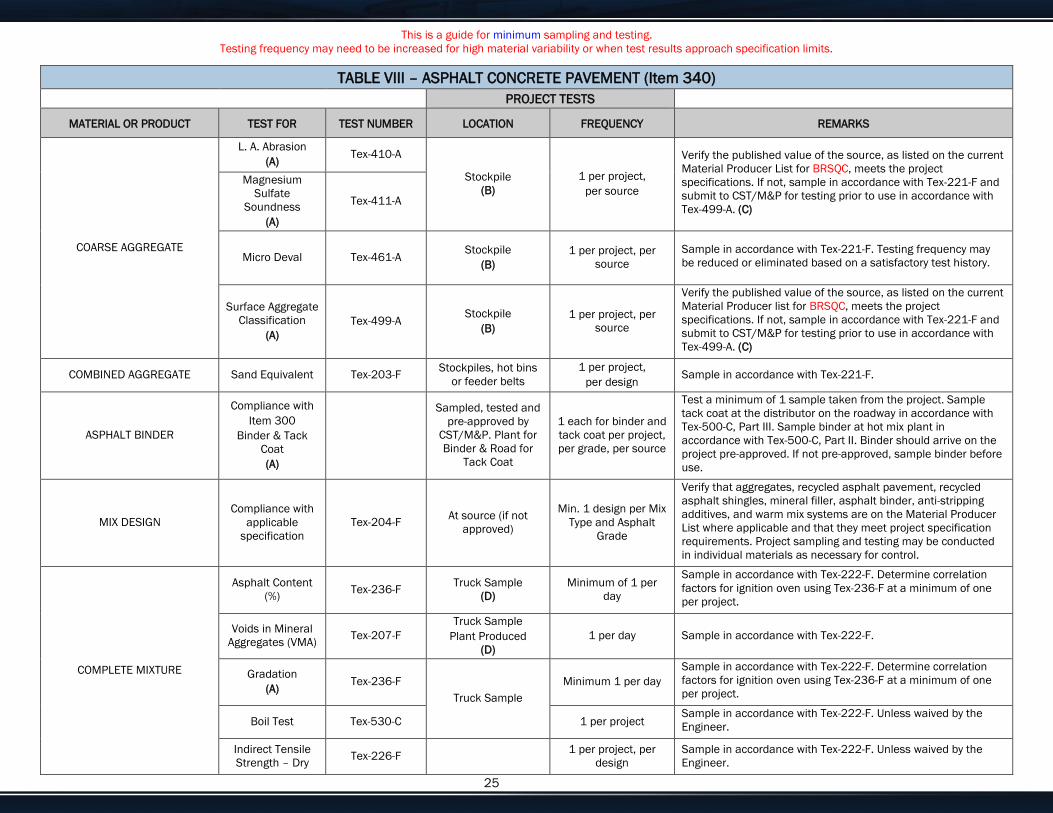
This is a guide for minimum sampling and testing.
Testing frequency may need to be increased for high material variability or when test results approach specification limits.
Enter customize text here for your needs or delete if not needed. 25
TABLE VIII – ASPHALT CONCRETE PAVEMENT (Item 340)
PROJECT TESTS
MATERIAL OR PRODUCT TEST FOR TEST NUMBER LOCATION FREQUENCY REMARKS
COARSE AGGREGATE
L. A. Abrasion
(A) Tex-410-A
Stockpile
(B)
1 per project,
per source
Verify the published value of the source, as listed on the current
Material Producer List for BRSQC, meets the project
specifications. If not, sample in accordance with Tex-221-F and
submit to CST/M&P for testing prior to use in accordance with
Tex-499-A. (C)
Magnesium
Sulfate
Soundness
(A)
Tex-411-A
Micro Deval Tex-461-A Stockpile
(B)
1 per project, per
source
Sample in accordance with Tex-221-F. Testing frequency may
be reduced or eliminated based on a satisfactory test history.
Surface Aggregate
Classification
(A)
Tex-499-A Stockpile
(B)
1 per project, per
source
Verify the published value of the source, as listed on the current
Material Producer list for BRSQC, meets the project
specifications. If not, sample in accordance with Tex-221-F and
submit to CST/M&P for testing prior to use in accordance with
Tex-499-A. (C)
COMBINED AGGREGATE Sand Equivalent Tex-203-F Stockpiles, hot bins
or feeder belts
1 per project,
per design Sample in accordance with Tex-221-F.
ASPHALT BINDER
Compliance with
Item 300
Binder & Tack
Coat
(A)
Sampled, tested and
pre-approved by
CST/M&P. Plant for
Binder & Road for
Tack Coat
1 each for binder and
tack coat per project,
per grade, per source
Test a minimum of 1 sample taken from the project. Sample
tack coat at the distributor on the roadway in accordance with
Tex-500-C, Part III. Sample binder at hot mix plant in
accordance with Tex-500-C, Part II. Binder should arrive on the
project pre-approved. If not pre-approved, sample binder before
use.
MIX DESIGN
Compliance with
applicable
specification
Tex-204-F At source (if not
approved)
Min. 1 design per Mix
Type and Asphalt
Grade
Verify that aggregates, recycled asphalt pavement, recycled
asphalt shingles, mineral filler, asphalt binder, anti-stripping
additives, and warm mix systems are on the Material Producer
List where applicable and that they meet project specification
requirements. Project sampling and testing may be conducted
in individual materials as necessary for control.
COMPLETE MIXTURE
Asphalt Content
(%) Tex-236-F
Truck Sample
(D)
Minimum of 1 per
day
Sample in accordance with Tex-222-F. Determine correlation
factors for ignition oven using Tex-236-F at a minimum of one
per project.
Voids in Mineral
Aggregates (VMA) Tex-207-F
Truck Sample
Plant Produced
(D)
1 per day Sample in accordance with Tex-222-F.
Gradation
(A) Tex-236-F
Truck Sample
Minimum 1 per day
Sample in accordance with Tex-222-F. Determine correlation
factors for ignition oven using Tex-236-F at a minimum of one
per project.
Boil Test Tex-530-C 1 per project Sample in accordance with Tex-222-F. Unless waived by the
Engineer.
Indirect Tensile
Strength – Dry Tex-226-F
1 per project, per
design
Sample in accordance with Tex-222-F. Unless waived by the
Engineer.
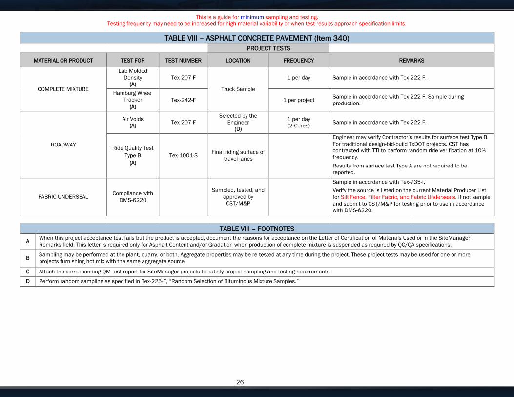
This is a guide for minimum sampling and testing.
Testing frequency may need to be increased for high material variability or when test results approach specification limits.
Enter customize text here for your needs or delete if not needed. 26
TABLE VIII – ASPHALT CONCRETE PAVEMENT (Item 340)
PROJECT TESTS
MATERIAL OR PRODUCT TEST FOR TEST NUMBER LOCATION FREQUENCY REMARKS
COMPLETE MIXTURE
Lab Molded
Density
(A)
Tex-207-F
Truck Sample
1 per day Sample in accordance with Tex-222-F.
Hamburg Wheel
Tracker
(A)
Tex-242-F 1 per project Sample in accordance with Tex-222-F. Sample during
production.
ROADWAY
Air Voids
(A) Tex-207-F
Selected by the
Engineer
(D)
1 per day
(2 Cores) Sample in accordance with Tex-222-F.
Ride Quality Test
Type B
(A)
Tex-1001-S Final riding surface of
travel lanes
Engineer may verify Contractor’s results for surface test Type B.
For traditional design-bid-build TxDOT projects, CST has
contracted with TTI to perform random ride verification at 10%
frequency.
Results from surface test Type A are not required to be
reported.
FABRIC UNDERSEAL Compliance with
DMS-6220
Sampled, tested, and
approved by
CST/M&P
Sample in accordance with Tex-735-I.
Verify the source is listed on the current Material Producer List
for Silt Fence, Filter Fabric, and Fabric Underseals. If not sample
and submit to CST/M&P for testing prior to use in accordance
with DMS-6220.
TABLE VIII – FOOTNOTES
A When this project acceptance test fails but the product is accepted, document the reasons for acceptance on the Letter of Certification of Materials Used or in the SiteManager
Remarks field. This letter is required only for Asphalt Content and/or Gradation when production of complete mixture is suspended as required by QC/QA specifications.
B Sampling may be performed at the plant, quarry, or both. Aggregate properties may be re-tested at any time during the project. These project tests may be used for one or more
projects furnishing hot mix with the same aggregate source.
C Attach the corresponding QM test report for SiteManager projects to satisfy project sampling and testing requirements.
D Perform random sampling as specified in Tex-225-F, “Random Selection of Bituminous Mixture Samples.”
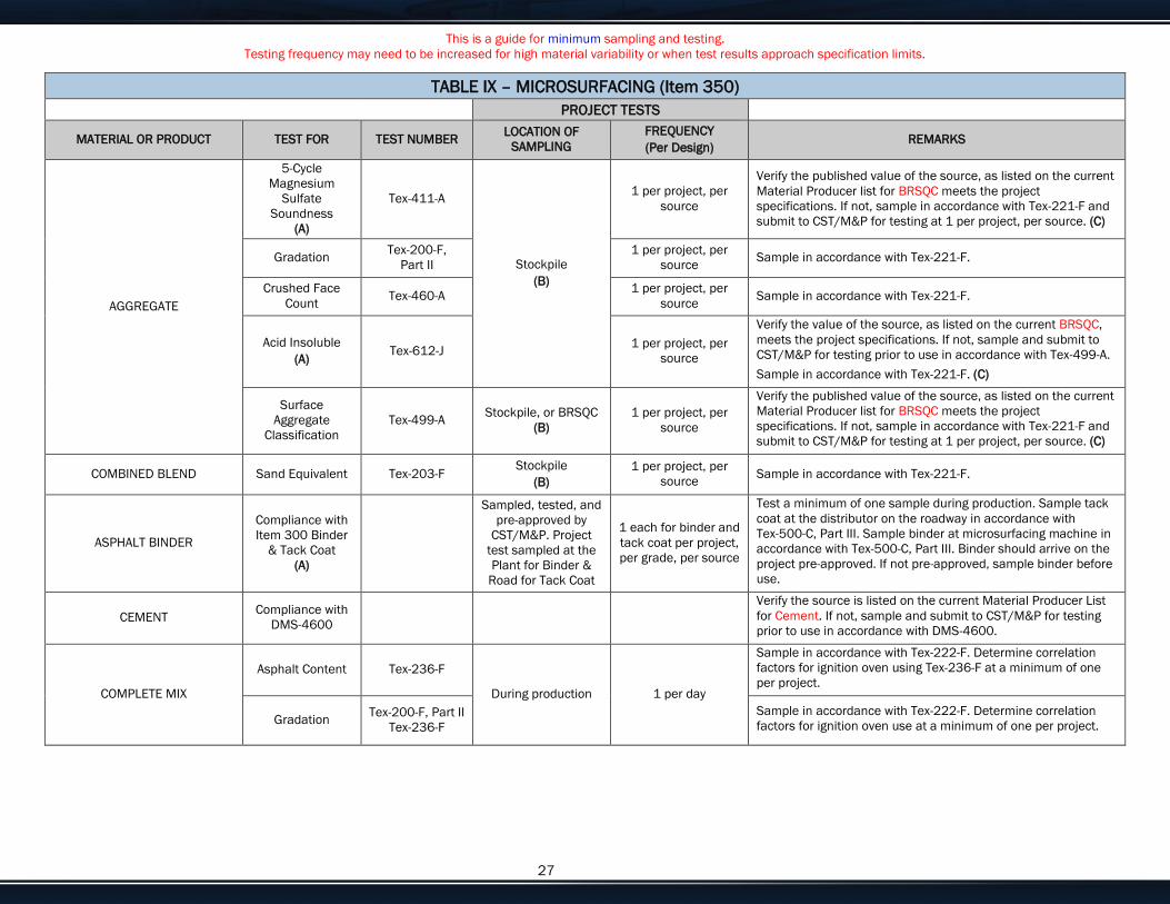
This is a guide for minimum sampling and testing.
Testing frequency may need to be increased for high material variability or when test results approach specification limits.
Enter customize text here for your needs or delete if not needed. 27
TABLE IX – MICROSURFACING (Item 350)
PROJECT TESTS
MATERIAL OR PRODUCT TEST FOR TEST NUMBER LOCATION OF
SAMPLING
FREQUENCY
(Per Design) REMARKS
AGGREGATE
5-Cycle
Magnesium
Sulfate
Soundness
(A)
Tex-411-A
Stockpile
(B)
1 per project, per
source
Verify the published value of the source, as listed on the current
Material Producer list for BRSQC meets the project
specifications. If not, sample in accordance with Tex-221-F and
submit to CST/M&P for testing at 1 per project, per source. (C)
Gradation Tex-200-F,
Part II
1 per project, per
source Sample in accordance with Tex-221-F.
Crushed Face
Count Tex-460-A
1 per project, per
source Sample in accordance with Tex-221-F.
Acid Insoluble
(A) Tex-612-J
1 per project, per
source
Verify the value of the source, as listed on the current BRSQC,
meets the project specifications. If not, sample and submit to
CST/M&P for testing prior to use in accordance with Tex-499-A.
Sample in accordance with Tex-221-F. (C)
Surface
Aggregate
Classification
Tex-499-A Stockpile, or BRSQC
(B)
1 per project, per
source
Verify the published value of the source, as listed on the current
Material Producer list for BRSQC meets the project
specifications. If not, sample in accordance with Tex-221-F and
submit to CST/M&P for testing at 1 per project, per source. (C)
COMBINED BLEND Sand Equivalent Tex-203-F Stockpile
(B)
1 per project, per
source Sample in accordance with Tex-221-F.
ASPHALT BINDER
Compliance with
Item 300 Binder
& Tack Coat
(A)
Sampled, tested, and
pre-approved by
CST/M&P. Project
test sampled at the
Plant for Binder &
Road for Tack Coat
1 each for binder and
tack coat per project,
per grade, per source
Test a minimum of one sample during production. Sample tack
coat at the distributor on the roadway in accordance with
Tex-500-C, Part III. Sample binder at microsurfacing machine in
accordance with Tex-500-C, Part III. Binder should arrive on the
project pre-approved. If not pre-approved, sample binder before
use.
CEMENT Compliance with
DMS-4600
Verify the source is listed on the current Material Producer List
for Cement. If not, sample and submit to CST/M&P for testing
prior to use in accordance with DMS-4600.
COMPLETE MIX
Asphalt Content Tex-236-F
During production 1 per day
Sample in accordance with Tex-222-F. Determine correlation
factors for ignition oven using Tex-236-F at a minimum of one
per project.
Gradation Tex-200-F, Part II
Tex-236-F
Sample in accordance with Tex-222-F. Determine correlation
factors for ignition oven use at a minimum of one per project.

This is a guide for minimum sampling and testing.
Testing frequency may need to be increased for high material variability or when test results approach specification limits.
Enter customize text here for your needs or delete if not needed. 28
TABLE IX – FOOTNOTES
A When this project acceptance test fails but the product is accepted, document the reasons for acceptance on the Letter of Certification of Materials Used or in the SiteManager
Remarks field. This letter is required only for Asphalt Content and/or Gradation when production of complete mixture is suspended as required by QC/QA specifications.
B Sampling may be performed at the plant, quarry, or both. Aggregate properties may be re-tested at any time during the project. These project tests may be used for one or more
projects furnishing hot mix with the same aggregate source.
C Attach the corresponding QM test report for SiteManager projects to satisfy project sampling and testing requirements.
D Each test performed that is based on a quantity of material is considered “or fraction thereof” for calculating number of tests.

PART D
BID QUANTITIES
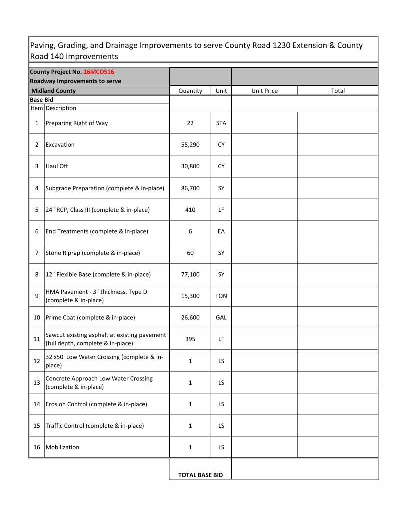
County Project No. 16MCO516
Roadway Improvements to serve
Midland County Quantity Unit Unit Price Total
Item Description
1 Preparing Right of Way 22 STA
2 Excavation 55,290 CY
3 Haul Off 30,800 CY
4 Subgrade Preparation (complete & in-place) 86,700 SY
5 24" RCP, Class III (complete & in-place) 410 LF
6 End Treatments (complete & in-place) 6 EA
7 Stone Riprap (complete & in-place) 60 SY
8 12" Flexible Base (complete & in-place) 77,100 SY
9HMA Pavement - 3" thickness, Type D
(complete & in-place)15,300 TON
10 Prime Coat (complete & in-place) 26,600 GAL
11Sawcut existing asphalt at existing pavement
(full depth, complete & in-place)395 LF
1232'x50' Low Water Crossing (complete & in-
place)1 LS
13Concrete Approach Low Water Crossing
(complete & in-place)1 LS
14 Erosion Control (complete & in-place) 1 LS
15 Traffic Control (complete & in-place) 1 LS
16 Mobilization 1 LS
Paving, Grading, and Drainage Improvements to serve County Road 1230 Extension & County
Road 140 Improvements
Base Bid
TOTAL BASE BID