Embed Size (px)
Citation preview
Paver System Five Control Box Overview Aug 2009
Control Box Overview
Paver System Five
Paver System Five Control Box Overview Aug 2009
Performance Menu SettingsReference Materials
7010-03740374 7010-03410374
Paver System Five Control Box Overview Aug 2009
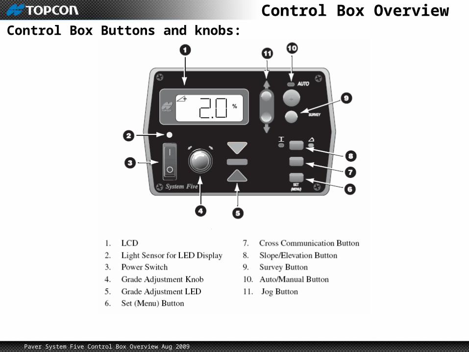
Control Box OverviewControl Box Buttons and knobs:
Paver System Five Control Box Overview Aug 2009
LCDLCD:
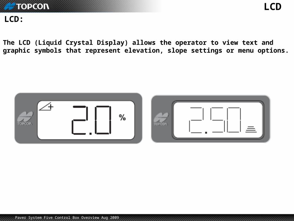
The LCD (Liquid Crystal Display) allows the operator to view text and graphic symbols that represent elevation, slope settings or menu options.
Paver System Five Control Box Overview Aug 2009
Light SensorLight Sensor:
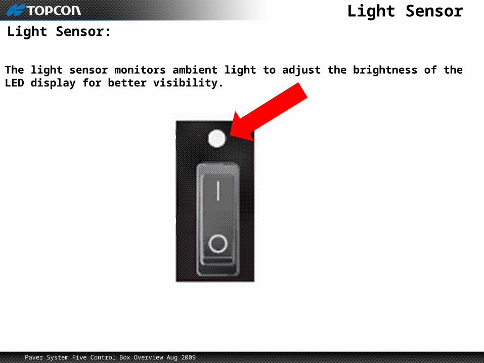
The light sensor monitors ambient light to adjust the brightness of the LED display for better visibility.
Paver System Five Control Box Overview Aug 2009
Power SwitchPower Switch:
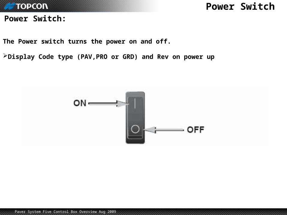
The Power switch turns the power on and off.
Display Code type (PAV,PRO or GRD) and Rev on power up
Paver System Five Control Box Overview Aug 2009
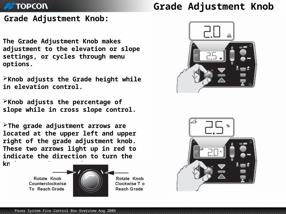
Grade Adjustment KnobGrade Adjustment Knob:
The Grade Adjustment Knob makes adjustment to the elevation or slope settings, or cycles through menu options.
Knob adjusts the Grade height while in elevation control.
Knob adjusts the percentage of slope while in cross slope control.
The grade adjustment arrows are located at the upper left and upper right of the grade adjustment knob. These two arrows light up in red to indicate the direction to turn the knob to reach on-grade.
Paver System Five Control Box Overview Aug 2009
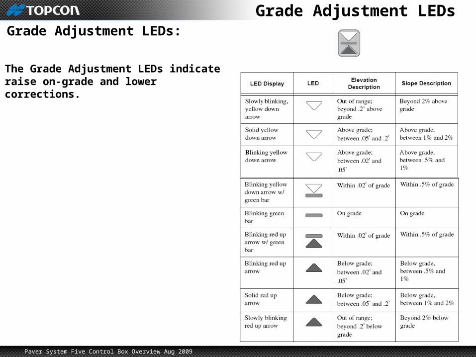
Grade Adjustment LEDsGrade Adjustment LEDs:
The Grade Adjustment LEDs indicate raise on-grade and lower corrections.
Paver System Five Control Box Overview Aug 2009
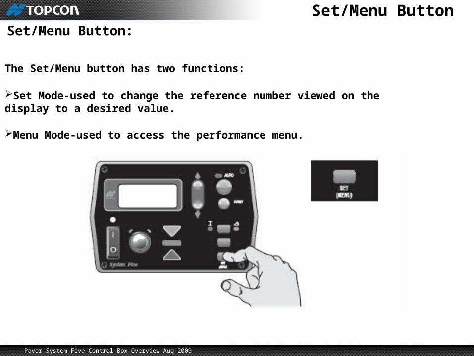
Set/Menu ButtonSet/Menu Button:
The Set/Menu button has two functions:
Set Mode-used to change the reference number viewed on the display to a desired value.
Menu Mode-used to access the performance menu.
Paver System Five Control Box Overview Aug 2009
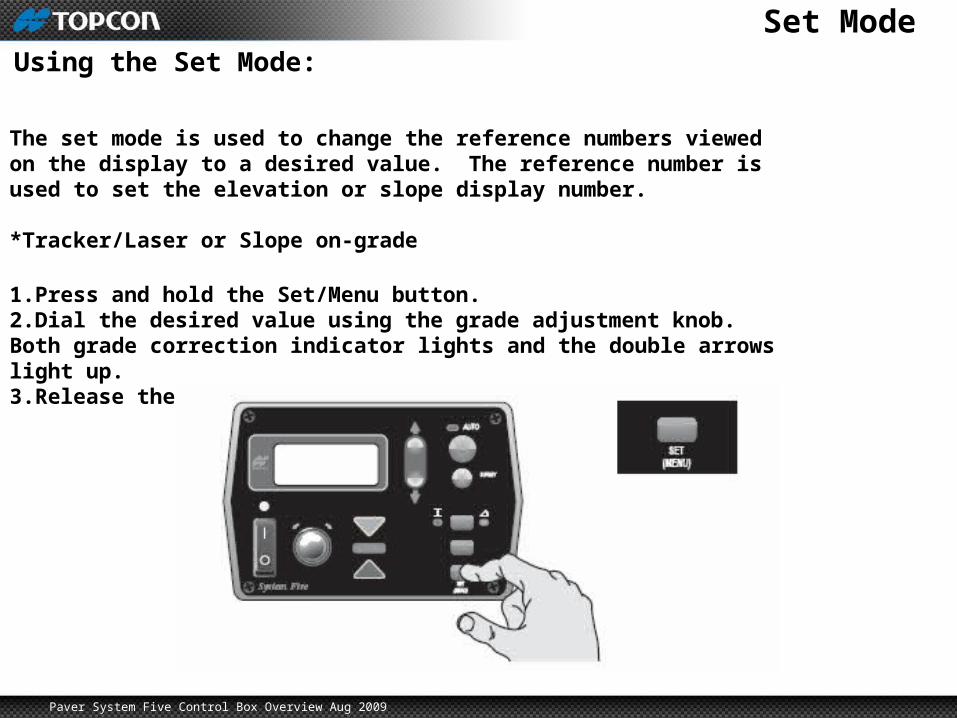
Set ModeUsing the Set Mode:
The set mode is used to change the reference numbers viewed on the display to a desired value. The reference number is used to set the elevation or slope display number.
*Tracker/Laser or Slope on-grade
1.Press and hold the Set/Menu button.2.Dial the desired value using the grade adjustment knob. Both grade correction indicator lights and the double arrows light up.3.Release the Set/Menu button and the value will be saved.
Paver System Five Control Box Overview Aug 2009
Menu ModeUsing the Menu Mode:
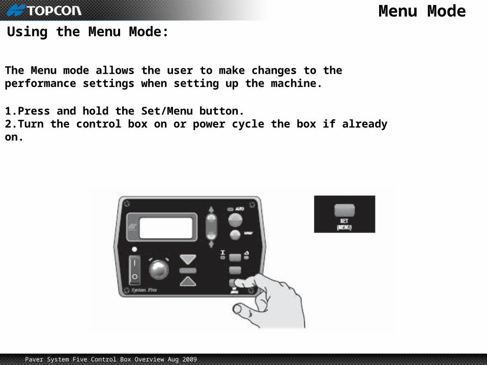
The Menu mode allows the user to make changes to the performance settings when setting up the machine.
1.Press and hold the Set/Menu button.2.Turn the control box on or power cycle the box if already on.
Paver System Five Control Box Overview Aug 2009
Cross CommunicationCross Communication Button:
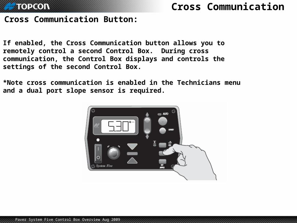
If enabled, the Cross Communication button allows you to remotely control a second Control Box. During cross communication, the Control Box displays and controls the settings of the second Control Box.
*Note cross communication is enabled in the Technicians menu and a dual port slope sensor is required.
Paver System Five Control Box Overview Aug 2009
Cross CommunicationCross Communication Button:
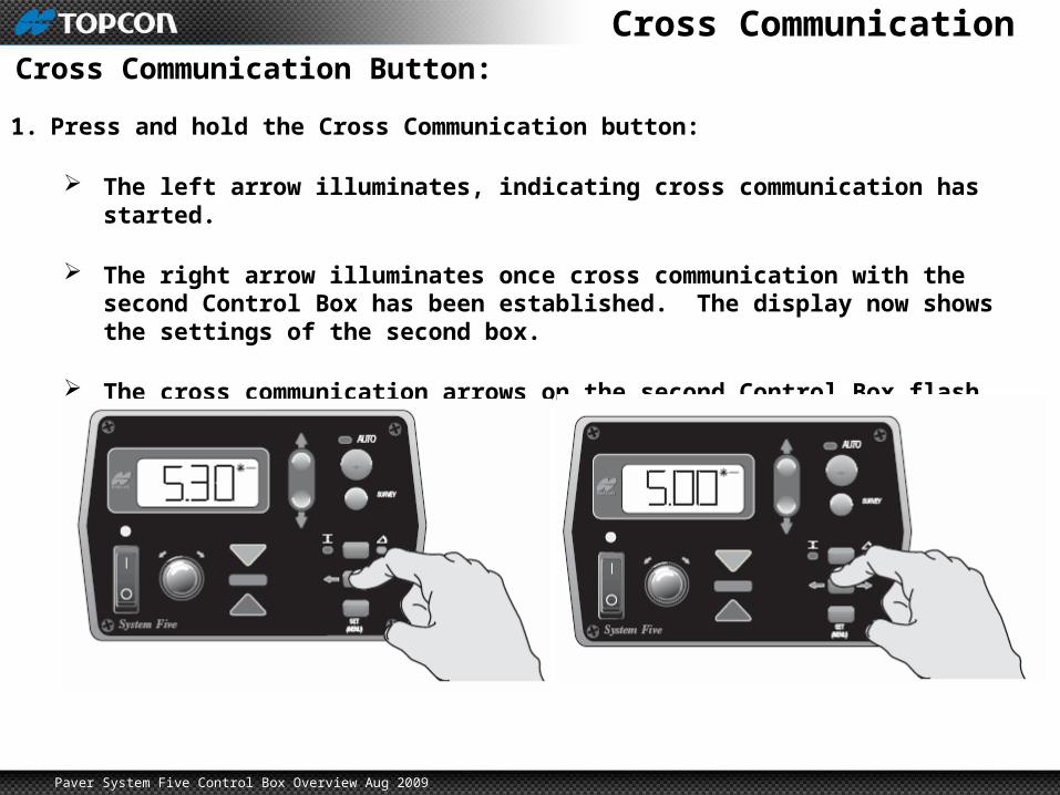
1. Press and hold the Cross Communication button:
The left arrow illuminates, indicating cross communication has started.
The right arrow illuminates once cross communication with the second Control Box has been established. The display now shows the settings of the second box.
The cross communication arrows on the second Control Box flash during cross communication.
Paver System Five Control Box Overview Aug 2009
Cross CommunicationCross Communication Button:
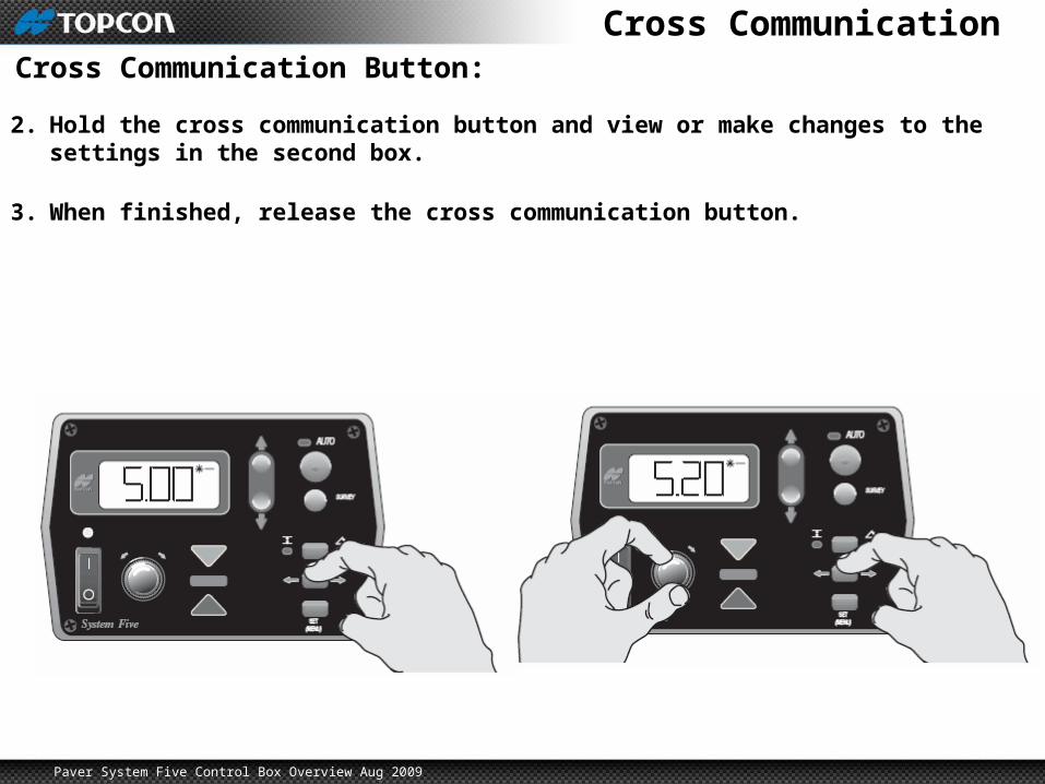
2. Hold the cross communication button and view or make changes to the settings in the second box.
3. When finished, release the cross communication button.
Paver System Five Control Box Overview Aug 2009
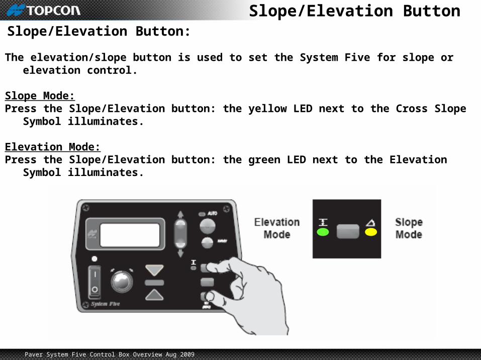
Slope/Elevation ButtonSlope/Elevation Button:
The elevation/slope button is used to set the System Five for slope or elevation control.
Slope Mode:Press the Slope/Elevation button: the yellow LED next to the Cross Slope Symbol
illuminates.
Elevation Mode:Press the Slope/Elevation button: the green LED next to the Elevation Symbol illuminates.
Paver System Five Control Box Overview Aug 2009
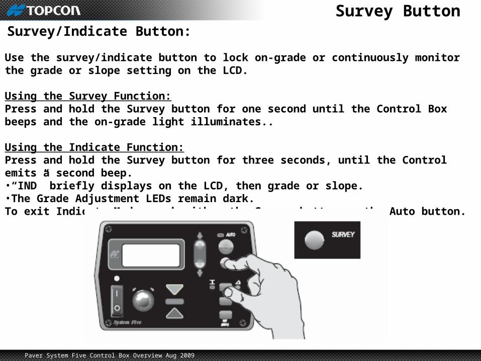
Survey ButtonSurvey/Indicate Button:
Use the survey/indicate button to lock on-grade or continuously monitor the grade or slope setting on the LCD.
Using the Survey Function:Press and hold the Survey button for one second until the Control Box beeps and the on-grade light illuminates..
Using the Indicate Function:Press and hold the Survey button for three seconds, until the Control emits a second beep.•“IND” briefly displays on the LCD, then grade or slope.•The Grade Adjustment LEDs remain dark.To exit Indicate Mode, push either the Survey button or the Auto button.
Paver System Five Control Box Overview Aug 2009
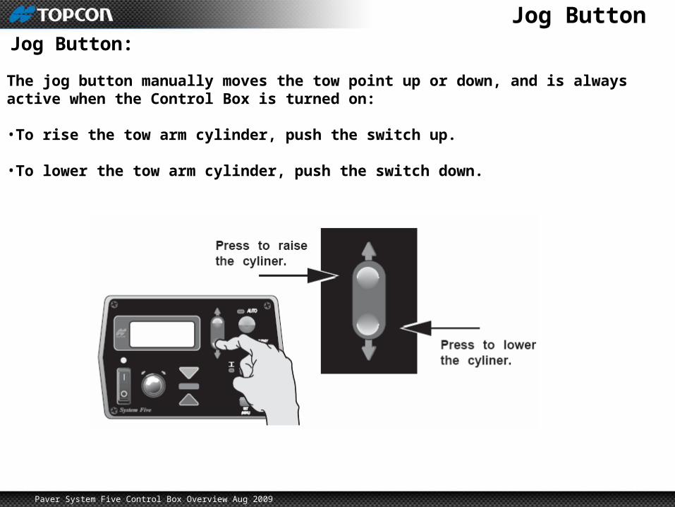
Jog ButtonJog Button:
The jog button manually moves the tow point up or down, and is always active when the Control Box is turned on:
•To rise the tow arm cylinder, push the switch up.
•To lower the tow arm cylinder, push the switch down.
Paver System Five Control Box Overview Aug 2009
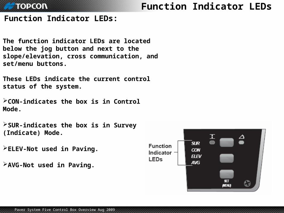
Function Indicator LEDsFunction Indicator LEDs:
The function indicator LEDs are located below the jog button and next to the slope/elevation, cross communication, and set/menu buttons.
These LEDs indicate the current control status of the system.
CON-indicates the box is in Control Mode.
SUR-indicates the box is in Survey (Indicate) Mode.
ELEV-Not used in Paving.
AVG-Not used in Paving.
Paver System Five Control Box Overview Aug 2009
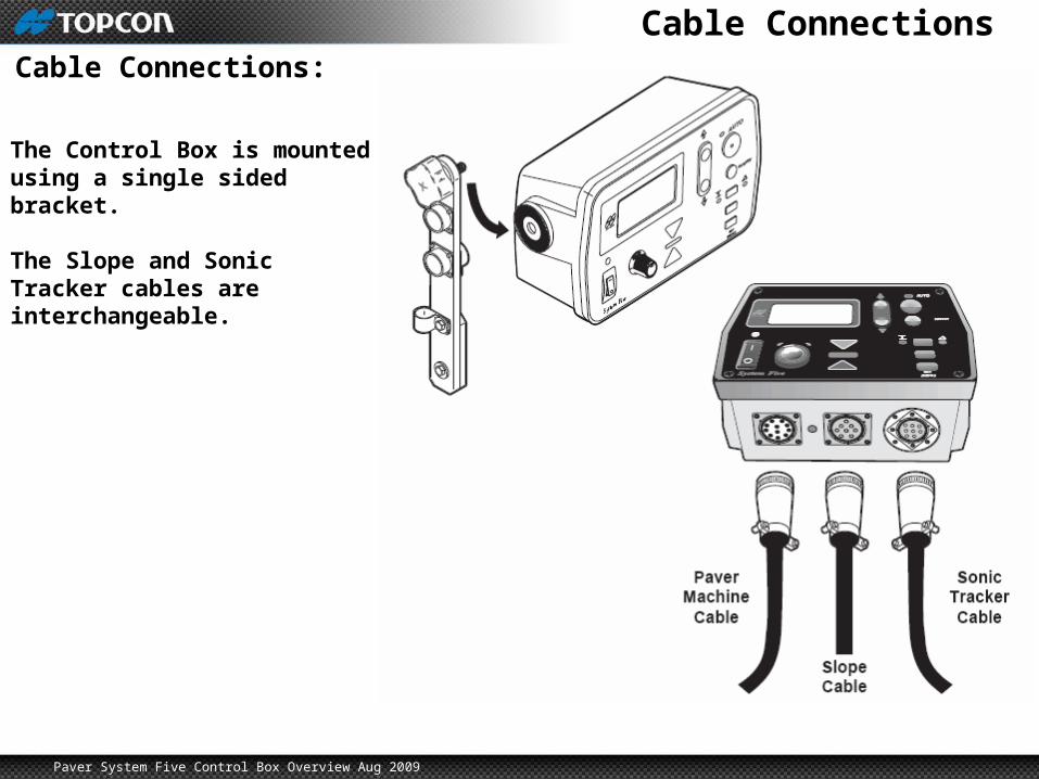
Cable ConnectionsCable Connections:
The Control Box is mounted using a single sided bracket.
The Slope and Sonic Tracker cables are interchangeable.

Paver System Five Control Box Overview Aug 2009
Control Box Overview
Paver System Five