Embed Size (px)
Citation preview
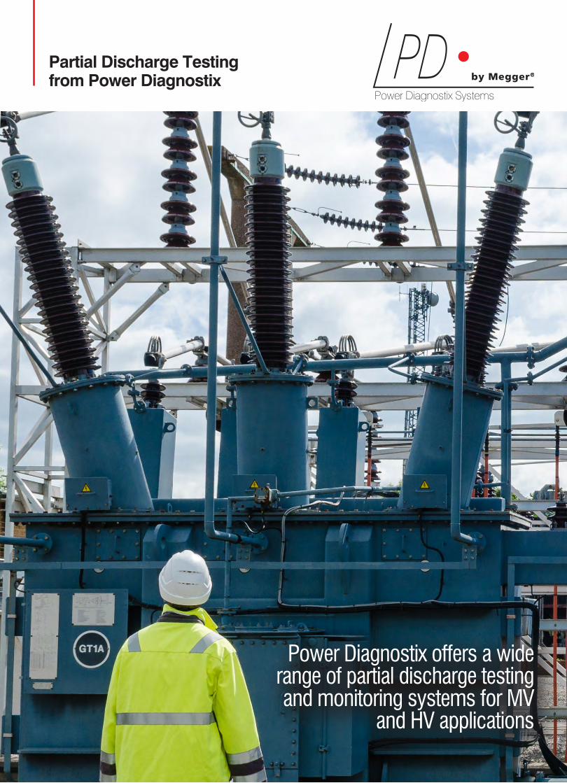
Partial Discharge Testing from Power Diagnostix
Power Diagnostix offers a wide range of partial discharge testing and monitoring systems for MV
and HV applications

2 Power Diagnostix www.pdix.com
Power Diagnostix
About Power Diagnostix
Power Diagnostix Systems GmbH provides quality instruments and engineering services for high-voltage diagnostic applications. Power Diagnostix has built a solid reputation since market introduction of our partial discharge detectors in early 1993. Our ICM series of digital partial discharge detectors is used for evaluation of electrical insulation by electric utilities, manufacturers, and research institutes worldwide.
In addition to digital partial discharge detectors, Power Diagnostix produces instruments for commissioning tests of GIS systems, automated control of high-voltage tests, fiber optic connections for analog signal transmission between instruments and sensors, and for other applications in high voltage. All of our instruments and specialized software products are developed in Aachen, Germany. Agents worldwide work in direct contact with us and our customers to find optimized solutions for their applications. The company’s principal engineers are active in several scientific committees.
In 2019, Power Diagnostix became a part of the Megger group.
About Megger
At Megger, we understand that keeping the power on is essential for the success of your business. That is why we are dedicated to creating, designing and manufacturing safe, reliable, easy-to-use portable test equipment and professional technical services backed by world-leading support and expertise.
We can assist your acceptance, commissioning and maintenance testing for predictive, diagnostic or routine purposes. By working closely with electrical utilities, standards bodies and technical institutions, we contribute to the dependability and advancement of the electrical supply industry ... keeping the Power on.
Our engineers actively participate in regulars’ committees, meetings with all the big trade associations around the world, training organisations and government organisations, to understand the needs of electrical contractors. So, when new legislation or rules are introduced, you can count on Megger to put your interests first, because Megger products and services help customers all over the world, improving their efficiency, reducing costs, and meeting standards. It operates globally, with dedicated field sales teams and distributors located all over the world and manufacturing plants in Germany, United States, Sweden and the United Kingdom. The commitment of Megger to industry is reflected in its technical leadership and in being the first to design and introduce many key innovative solutions to the markets.
Megger offers a full service, repair and calibration service accredited to ISO9001:2015 and ISO14001:2015.
www.pdix.com 3
Contents
TABLE OF CONTENTS
Product selection guide P04 - P05
Product Application
Transformers P06 - P07
Rotating Machines P08 - P09
Switchgear (GIS/GIL and AIS) P10 - P11
Cables P12 - P13
PD Measurement Devices
ICMsystem Gen. 5 P14 - P15
ICMcompact P16
AIAcompact P17
ICMflex P18
PD Monitoring Systems
GISmonitor P19
GISmonitor Portable P20
ICMmonitor Portable P21
ICMmonitor CA P22
Calibrators
CAL1, CAL2, CAL3 Series P23
PD Accessories
Sensors P24
Couplers P25
Quadrupoles P25
Preamplifiers P26 - P27
This catalogue covers only a part of the entire product range. Visit www.pdix.com to learn more about the complete range of products and services.
4 Power Diagnostix www.pdix.com www.pdix.com 5
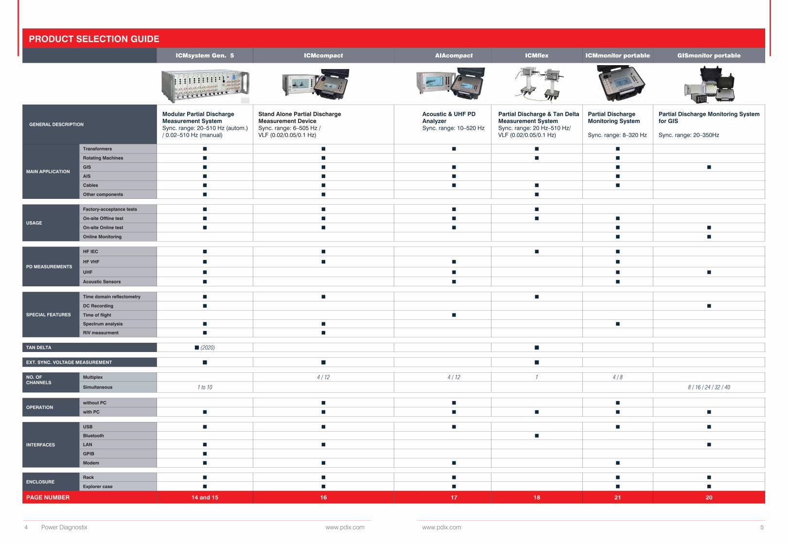
PRODUCT SELECTION GUIDE
ICMsystem Gen. 5 ICMcompact AIAcompact ICMflex ICMmonitor portable GISmonitor portable
GENERAL DESCRIPTION
Modular Partial Discharge Measurement SystemSync. range: 20–510 Hz (autom.) / 0.02–510 Hz (manual)
Stand Alone Partial Discharge Measurement DeviceSync. range: 6–505 Hz / VLF (0.02/0.05/0.1 Hz)
Acoustic & UHF PD Analyzer Sync. range: 10–520 Hz
Partial Discharge & Tan Delta Measurement System Sync. range: 20 Hz–510 Hz/ VLF (0.02/0.05/0.1 Hz)
Partial Discharge Monitoring System
Sync. range: 8–320 Hz
Partial Discharge Monitoring System for GIS
Sync. range: 20–350Hz
MAIN APPLICATION
Transformers n n n n n
Rotating Machines n n n n
GIS n n n n n
AIS n n n n
Cables n n n n n
Other components n n n
USAGE
Factory-acceptance tests n n n n
On-site Offline test n n n n n
On-site Online test n n n n n
Online Monitoring n n
PD MEASUREMENTS
HF IEC n n n n
HF VHF n n n n
UHF n n n n
Acoustic Sensors n n n
SPECIAL FEATURES
Time domain reflectometry n n n
DC Recording n n
Time of flight n
Spectrum analysis n n n
RIV measurment n n
TAN DELTA n (2020) n
EXT. SYNC. VOLTAGE MEASUREMENT n n n
NO. OF CHANNELS
Multiplex 4 / 12 4 / 12 1 4 / 8
Simultaneous 1 to 10 8 / 16 / 24 / 32 / 40
OPERATIONwithout PC n n n
with PC n n n n n n
INTERFACES
USB n n n n n
Bluetooth n
LAN n n n
GPIB n
Modem n n n n
ENCLOSURERack n n n n n
Explorer case n n n n n
PAGE NUMBER 14 and 15 16 17 18 21 20
www.pdix.com 7
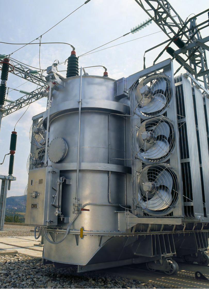
Product Application Transformers
Partial discharge measurements on power and distribution transformers are a proven tool to identify and locate insulation defects within windings, instrument transformers, bushings, tap changers, or other accessories. Besides providing the required equipment for factor acceptance testing (FAT), Power Diagnostix offers a wide range of instruments for onsite investigations and for continuous online monitoring. Such offline or online measurements in the field generally serve as an in-depth verification of an initial trigger by a PD-monitoring system or suspicious dissolved gas analysis results, and can provide essential information about ongoing deterioration of components of the active part and bushings, for instance. Currently, offline partial discharge testing in the field after commissioning of new units is an emerging trend, and already proved to be very effective to detect assembling or processing deficiencies. The permanent PD-surveillance of transformers in the grid is these days a proven technology to prevent unforeseen outages or irreparable damage. Accurate monitoring of phase resolved PD-patterns and alarm thresholds are the required indicators to monitor in order to avoid a breakdown or system failure. With the ICMmonitor, Power Diagnostix provide such compact, stand-alone and remotely accessible continuous monitoring system for power transformers offering accurate alarm functionality with consequent pre-warning messages to prevent worst case scenario´s.
The multi-channel ICMsystem Gen. 5 greatly simplifies the PD acceptance tests on large power transformers. With its true parallel PD-acquisition of up to on ten channels, the overall testing period is substantially shortened by features such the automatic calibration cross coupling matrix. A typical package for advanced PD analysis consists of a multichannel ICMsystem offering both narrow and wide band PD-pattern acquisition according to IEC60270. The instrument comes with an embedded spectrum analyzer for advanced PD-analysis in frequency domain. Moreover, it is an excellent tool to use in case of noisy test environments. New in this 5th generation is the embedded digital storage oscilloscope (DSO) for time domain analysis of electrical and acoustic signals. The ICMsystem software further offers direct transmission of acoustic time domain measurements to the ICMacoustic PD-location software, providing an accurate graphical and mathematical triangulation functionality to locate PD-defects in the main tank with high precision.
The ICMcompact with SPEC option is a good compromise for routine factory PD-testing of distribution class transformers and instrument transformers. Its user friendly interface enables non-PD-experts to efficiently handle factory acceptance testing. The embedded 40kHz-10MHz spectrum analyzer and effective noise gating features are excellent tools to cope with noisy factory environments In addition to the noise suppression functions of the instruments, Power Diagnostix offers a wide range of high voltage filters for induced or applied voltage testing.
In addition to the noise supression functions of the instruments, Power Diagnostix offers a wide range of high voltage filters for induced or applied voltage testing.
PD MONITORING
TYPICAL PACKAGES
Partial discharge monitoring has become increasingly important in the past few years. Besides other parameters such as dissolved gas analysis, temperatures, vibrations, or load conditions, etc., the PD trending information completes a full set of monitoring data of a power transformer in the field. A wide range of standard bushing adapters (BA) is available to connect the measurement system to the capacitive tap of condenser bushings. Even special designs are available on request. Additionally, the standard setup using the bushing test tap could be extended with UHF drain valve sensors or embedded antenna in flanges. A good alternative for continuous monitoring are periodical online PD-measurements using an ICMsystem or ICMmonitor portable. Signal decoupling can in such case be done by either temporary installed measuring impedances or a permanent setup with bushing adapters (BA) and bushing coupling units (BCU).
Set for power transformer acceptance testing:
z 1 x ICMsystem Gen. 5 z 1 x Built-in TCP/IP interface z 1 x GPIB interface z 1 x Software ICMsystem Gen. 5 z 1 x Impulse calibrator CAL1D or CAL1B z 9 x Preamplifier RPA1 or RPA1L z 8 x Quadrupole CIL4M/V0μ5/2μ0 z 3 x Quadrupole CIL5M/V4μ0
z 3x T100/100 high voltage filter
Set for distribution transformer acceptance testing:
z 1 x ICMsystem Gen. 5 or ICMcompact (incl. MUX4) z 1 x GPIB Interface (with ICMsystem) z 1 x Software ICMsystem Gen. 5/ICMcompact z 1 x Impulse calibrator CAL1D z 4 x Preamplifier RPA1 or RPA1L z 3 x Coupling capacitor CC100B/V z 3 x T30/xx or T50/xx high voltage filter
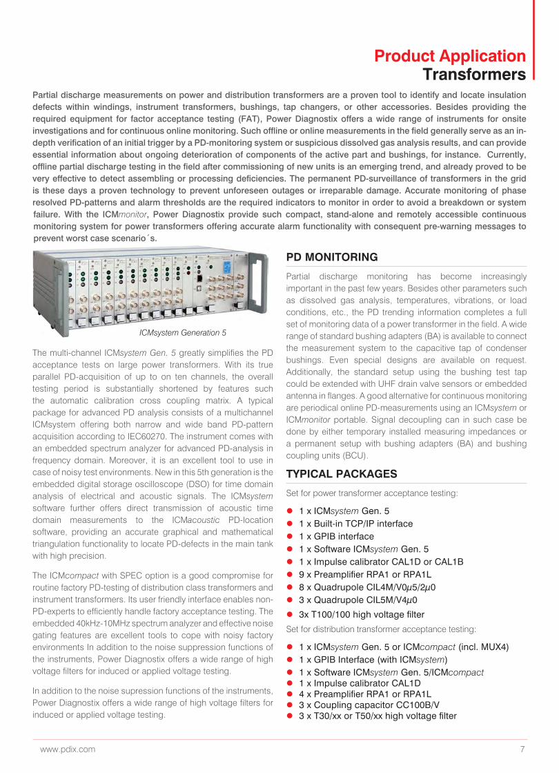
ICMsystem Generation 5

www.pdix.com 9
Product Application Rotating Machines
The epoxy-mica stator winding insulation system of rotating machines “forgiving” insulation system. Due its dielectric stability, partial discharge activity acts as an indicator for a variety of defect mechanisms. Besides the normal thermal ageing, further problems, such as end winding contamination, bar or overhang vibrations, deterioration of grading layers, loose wedges or large internal delaminations are common practice and can be classified by analysis of the phase resolved pattern properties. Partial discharge testing and monitoring on generators and large motors offers a detailed stator winding condition assessment. This helps avoiding unplanned outages as well as scheduling efficient maintenance turn arounds.
PD MEASUREMENTS
Power Diagnostix offers various instruments for continuous monitoring, schedule-based routine testing and in-depth analysis of rotating machinery. The instruments and their control software were continuously improved based on the feedback and requirements of the end users. Permanently installed partial discharge couplers greatly simplify periodical on-line testing using the ICMsystem without any interruption or downtime. Continuous on-line PD-monitoring with a permanently installed ICMmonitor helps optimizing maintenance intervals and reducing costs, while improving the level of equipment reliability.
PARTIAL DISCHARGE MONITORING
LARGE MOTORS
TYPICAL PACKAGES
Based on the stand-alone ICMmonitor unit connected to an individual machine, larger networks supervising a multitude of generators in combined-cycle thermal power plants or pump-storage hydro power plant have been realized. Such networks include full control of the local instrument via global Intranet access as well as visualization of the monitoring data in monitoring centers. The ICMmonitor software offers automated scanning, pattern acquisition, and analysis of the trending data, while the ICMserver software operates in the background to supervise the communication between the individual instruments and data servers.
High voltage motors are the main assets to keep compressors, cooling pumps, extruders and or large fans running in refineries, oil and gas plants, chemical and petrochemical industry. Here, unplanned outages can cause immense losses. Not only for the HV-motor in particular, but, to clean pipelines with remaining
Advanced PD measurement system (off-line and on-line):
z 1 x ICMsystem Gen. 5 (incl. option spectrum analysis)
z 1 x ICMsystem software
z 1 x GPIB interface
z 2 x Preamplifier RPA1H
z 1 x Preamplifier RPA2 (for online testing)
z 1 x High frequency current transformer CT1 or CT100 (optional)
z 1 x Impulse calibrator CAL1B
z 1 x Set of cables
z 1 x Offline Coupling capacitor, e. g. CC25B/V
Standard PD test system (off-line):
z 1 x ICMcompact (optionally, MUX4 & gating)
z 1 x ICMcompact software
z 1 x Preamplifier RPA1 or RPA1e
z 1x Impulse calibrator CAL1B
z 1 x Set of cables
z 1 x Offline Coupling capacitor, e. g. CC25B/V
Combined PD and TD measurement equipment (off-line):
z 1 x ICMflex incl. software
z 1 x Impulse calibrator CAL1B
z 1 x Set of cables
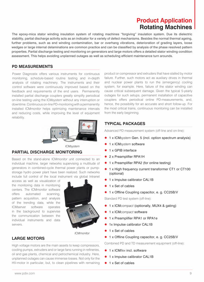
ICMmonitor
ICMsystem
product or compressor and extruders that have stalled by motor failure. Further, such motors act as auxiliary drives in thermal and nuclear power plants to run the (emergency) cooling system, for example. Here, failure of the stator winding can cause critical subsequent damage. Given the typical 5-yearly outages for such setups, permanent installation of capacitive couplers offers periodical online PD-measurements, and, hence, the possibility for an accurate and short follow-up. For the most critical trains, continuous monitoring can be installed from the early beginning.
www.pdix.com 11
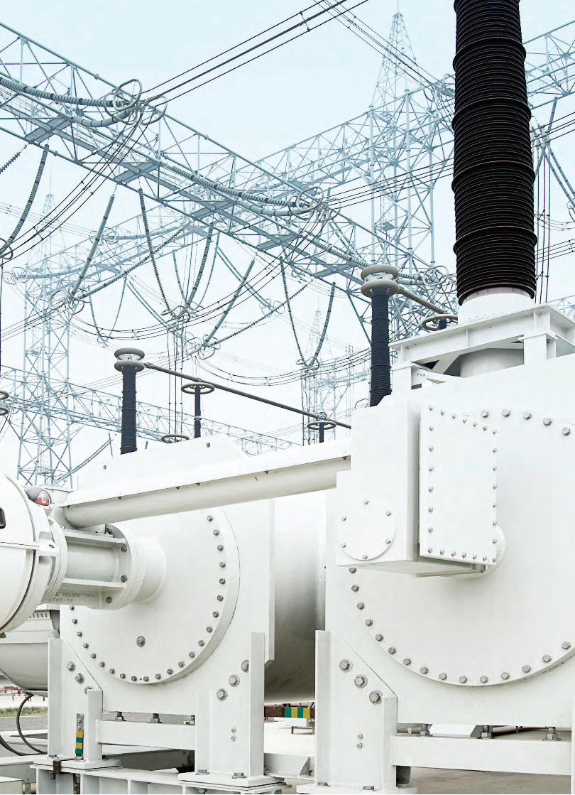
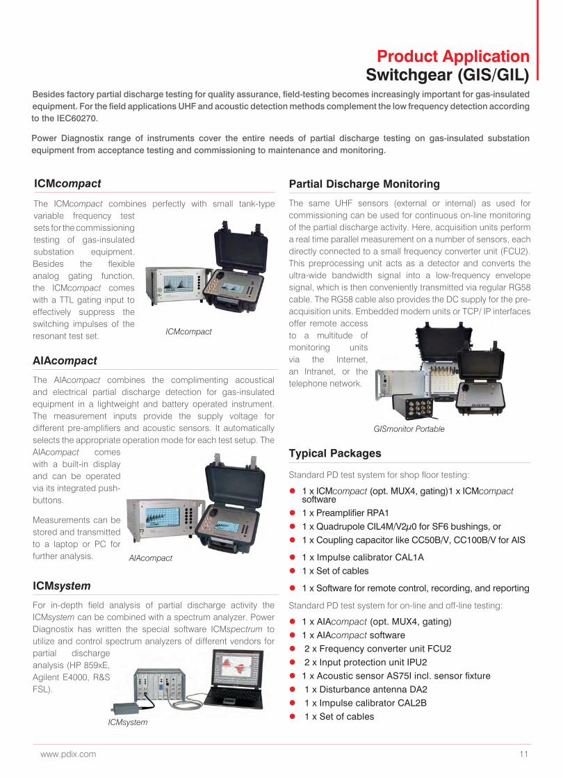
Product Application Switchgear (GIS/GIL)
Besides factory partial discharge testing for quality assurance, field-testing becomes increasingly important for gas-insulated equipment. For the field applications UHF and acoustic detection methods complement the low frequency detection according to the IEC60270.
Power Diagnostix range of instruments cover the entire needs of partial discharge testing on gas-insulated substation equipment from acceptance testing and commissioning to maintenance and monitoring.
ICMcompact
The ICMcompact combines perfectly with small tank-type variable frequency test sets for the commissioning testing of gas-insulated substation equipment. Besides the flexible analog gating function, the ICMcompact comes with a TTL gating input to effectively suppress the switching impulses of the resonant test set.
AIAcompact
ICMsystem
Partial Discharge Monitoring
Typical Packages
The AIAcompact combines the complimenting acoustical and electrical partial discharge detection for gas-insulated equipment in a lightweight and battery operated instrument. The measurement inputs provide the supply voltage for different pre-amplifiers and acoustic sensors. It automatically selects the appropriate operation mode for each test setup. The AIAcompact comes with a built-in display and can be operated via its integrated push-buttons.
Measurements can be stored and transmitted to a laptop or PC for further analysis.
For in-depth field analysis of partial discharge activity the ICMsystem can be combined with a spectrum analyzer. Power Diagnostix has written the special software ICMspectrum to utilize and control spectrum analyzers of different vendors for partial discharge analysis (HP 859xE, Agilent E4000, R&S FSL).
The same UHF sensors (external or internal) as used for commissioning can be used for continuous on-line monitoring of the partial discharge activity. Here, acquisition units perform a real time parallel measurement on a number of sensors, each directly connected to a small frequency converter unit (FCU2). This preprocessing unit acts as a detector and converts the ultra-wide bandwidth signal into a low-frequency envelope signal, which is then conveniently transmitted via regular RG58 cable. The RG58 cable also provides the DC supply for the pre-acquisition units. Embedded modem units or TCP/ IP interfaces offer remote access to a multitude of monitoring units via the Internet, an Intranet, or the telephone network.
Standard PD test system for shop floor testing:
z 1 x ICMcompact (opt. MUX4, gating)1 x ICMcompact software
z 1 x Preamplifier RPA1 z 1 x Quadrupole CIL4M/V2µ0 for SF6 bushings, or z 1 x Coupling capacitor like CC50B/V, CC100B/V for AIS
z 1 x Impulse calibrator CAL1A z 1 x Set of cables
z 1 x Software for remote control, recording, and reporting
Standard PD test system for on-line and off-line testing:
z 1 x AIAcompact (opt. MUX4, gating) z 1 x AIAcompact software z 2 x Frequency converter unit FCU2 z 2 x Input protection unit IPU2 z 1 x Acoustic sensor AS75I incl. sensor fixture z 1 x Disturbance antenna DA2 z 1 x Impulse calibrator CAL2B z 1 x Set of cables
ICMcompact
GISmonitor Portable
AIAcompact
ICMsystem
www.pdix.com 13
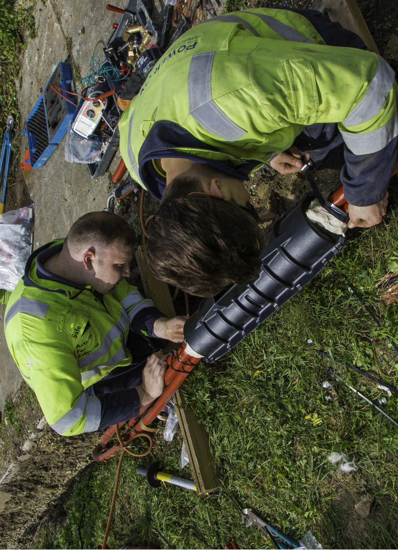
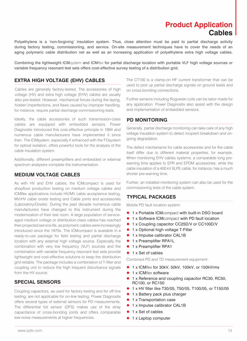
Product Application Cables
Polyethylene is a ‘non-forgiving’ insulation system. Thus, close attention must be paid to partial discharge activity during factory testing, commissioning, and service. On-site measurement techniques have to cover the needs of an aging polymeric cable distribution net as well as an increasing application of polyethylene extra high voltage cables. Combining the lightweight ICMsystem and ICMflex for partial discharge location with portable VLF high voltage sources or variable frequency resonant test sets offers cost-effective survey testing of a distribution grid.
EXTRA HIGH VOLTAGE (EHV) CABLES
Cables are generally factory-tested. The accessories of high voltage (HV) and extra high voltage (EHV) cables are usually also pre-tested. However, mechanical forces during the laying, hidden imperfections, and flaws caused by improper handling, for instance, require partial discharge commissioning tests.
Ideally, the cable accessories of such transmission-class cables are equipped with embedded sensors. Power Diagnostix introduced this cost-effective principle in 1994 and numerous cable manufacturers have implemented it since then. The ICMsystem, especially if enhanced with the FOsystem for optical isolation, offers powerful tools for the analysis of the cable insulation system.
Additionally, different preamplifiers and embedded or external spectrum analyzers complete the instrumentation.
MEDIUM VOLTAGE CABLES
SPECIAL SENSORS
PD MONITORING
TYPICAL PACKAGES
As with HV and EHV cables, the ICMcompact is used for shopfloor production testing on medium voltage cables and ICMflex applications include HV/MV cable acceptance testing, MV/HV cable onsite testing and Cable joints and accessories (Laboratory/Onsite). During the past decade numerous cable manufacturers have changed to this instrument during the modernization of their test room. A large population of service-aged medium voltage or distribution-class cables has reached their projected service life, as polymeric cables were increasingly introduced since the 1970s. The ICMcompact is available in a ready-to-use package for field testing and partial discharge location with any external high voltage source. Especially the combination with very low frequency (VLF) sources and the combination with variable frequency resonant test sets provide lightweight and cost-effective solutions to keep the distribution grid reliable. The package includes a combination of T-filter and coupling unit to reduce the high frequent disturbance signals from the HV source.
Coupling capacitors, as used for factory testing and for off-line testing, are not applicable for on-line testing. Power Diagnostix offers several types of external sensors for PD measurements. The differential foil sensor (DFS) makes use of the stray capacitance of cross-bonding joints and offers comparable low-noise measurements at higher frequencies.
Generally, partial discharge monitoring can take care of any high voltage insulation system to detect incipient breakdown and on-going degradation.
The defect mechanisms for cable accessories and for the cable itself differ due to different material properties, for example. When monitoring EHV cables systems, a comparable long pre-warning time applies to EPR and EPDM accessories, while the cable insulation of a 400 kV XLPE cable, for instance, has a much shorter pre-warning time.
Further, an installed monitoring system can also be used for the commissioning tests of the cable system.
Mobile PD fault location system:
z 1 x Portable ICMcompact with built-in DSO board z 1 x Software ICMcompact with PD fault location z 1 x Coupling capacitor CC25D/V or CC100D/V z 1 x Optional high voltage T-Filter z 1 x Impulse calibrator CAL1B z 1 x Preamplifier RPA1L z 1 x Preamplifier RPA1
z 1 x Set of cables
Combined PD and TD measurement equipment:
z 1 x ICMflex for 30kV, 50kV, 100kV, or 150kVrms z 1 x ICMflex software z 1 x Reference and coupling capacitor RC30, RC50,
RC100, or RC150 z 1 x HV filter like T30/05, T50/05, T100/05, or T150/05 z 1 x Battery pack plus charger z 1 x Transportation case z 1 x Impulse calibrator CAL1B
z 1 x Set of cables
z 1 x Laptop computer
The CT100 is a clamp-on HF current transformer that can be used to pick up partial discharge signals on ground leads and on cross-bonding connections.
Further sensors including Rogowski coils can be tailor-made for any application. Power Diagnostix also assist with the design and implementation of embedded sensors.
14 Power Diagnostix www.pdix.com
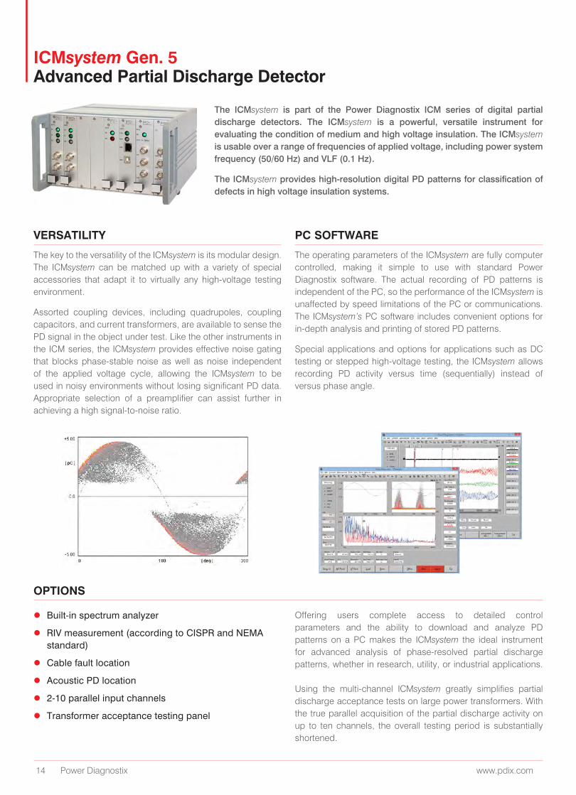
ICMsystem Gen. 5 Advanced Partial Discharge Detector
VERSATILITY
OPTIONS
PC SOFTWARE
The ICMsystem is part of the Power Diagnostix ICM series of digital partial discharge detectors. The ICMsystem is a powerful, versatile instrument for evaluating the condition of medium and high voltage insulation. The ICMsystem is usable over a range of frequencies of applied voltage, including power system frequency (50/60 Hz) and VLF (0.1 Hz).
The ICMsystem provides high-resolution digital PD patterns for classification of defects in high voltage insulation systems.
The key to the versatility of the ICMsystem is its modular design. The ICMsystem can be matched up with a variety of special accessories that adapt it to virtually any high-voltage testing environment.
Assorted coupling devices, including quadrupoles, coupling capacitors, and current transformers, are available to sense the PD signal in the object under test. Like the other instruments in the ICM series, the ICMsystem provides effective noise gating that blocks phase-stable noise as well as noise independent of the applied voltage cycle, allowing the ICMsystem to be used in noisy environments without losing significant PD data. Appropriate selection of a preamplifier can assist further in achieving a high signal-to-noise ratio.
The operating parameters of the ICMsystem are fully computer controlled, making it simple to use with standard Power Diagnostix software. The actual recording of PD patterns is independent of the PC, so the performance of the ICMsystem is unaffected by speed limitations of the PC or communications. The ICMsystem’s PC software includes convenient options for in-depth analysis and printing of stored PD patterns.
Special applications and options for applications such as DC testing or stepped high-voltage testing, the ICMsystem allows recording PD activity versus time (sequentially) instead of versus phase angle.
z Built-in spectrum analyzer
z RIV measurement (according to CISPR and NEMA standard)
z Cable fault location
z Acoustic PD location
z 2-10 parallel input channels
z Transformer acceptance testing panel
Offering users complete access to detailed control parameters and the ability to download and analyze PD patterns on a PC makes the ICMsystem the ideal instrument for advanced analysis of phase-resolved partial discharge patterns, whether in research, utility, or industrial applications. Using the multi-channel ICMsystem greatly simplifies partial discharge acceptance tests on large power transformers. With the true parallel acquisition of the partial discharge activity on up to ten channels, the overall testing period is substantially shortened.
www.pdix.com 15
ICMsystem Gen. 5 Advanced Partial Discharge Detector
INDEPENDENT CHANNELS SPECIALIZED SOFTWARE
PATTERN ACQUISITION
For each of the partial discharge measurement channel an independent quadrupole, preamplifier, and amplifier plug-in board is required.
Internally, the system controller processes the discharge readings acquired for each channel in a true bipolar peak amplitude acquisition.
The ICMsystem control software for transformer acceptance testing offers manual and automatic modes for the acceptance test. Reporting is simplified with MS Word and plain text output formats. The reports are based on user-selectable templates.
In acceptance test mode, the software shows eight meter displays, each indicating PD level, voltage, and frequency of the specific channel. With the center display, the automatically or manually triggered values are presented in list mode or as a strip-chart. Further, during calibration, the cross-coupling matrix between the channels is built up, which offers essential information in case of PD location measurements on transformers. Additionally, the multi-channel ICMsystem software provides the user with all the features known from the standard ICMsystem, such as multi-channel consecutive pattern acquisition, movie-like replay, or statistical evaluation, for instance.
In addition to the parallel acquisition of the PD activity for the meter and stripchart displays, the pattern acquisition core offers the defect identification capabilities of the phase-resolved partial discharge analysis.
The ICMsystem for power transformer acceptance testing is the first commercially available partial discharge detector with true parallel acquisition on eight channels. The instrument and its software greatly simplify the testing procedures and, thus, reduce the time the transformer needs to stay in the acceptance test lab.
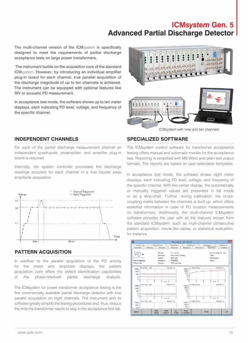
The multi-channel version of the ICMsystem is specifically designed to meet the requirements of partial discharge acceptance tests on large power transformers.
The instrument builds on the acquisition core of the standard ICMsystem. However, by introducing an individual amplifier plug-in board for each channel, true parallel acquisition of the discharge magnitude of up to ten channels is achieved. The instrument can be equipped with optional features like RIV or acoustic PD measurement.
In acceptance test mode, the software shows up to ten meter displays, each indicating PD level, voltage, and frequency of the specific channel.
ICMsystem with nine and ten channels
16 Power Diagnostix www.pdix.com
ICMcompact Digital Partial Discharge Detector
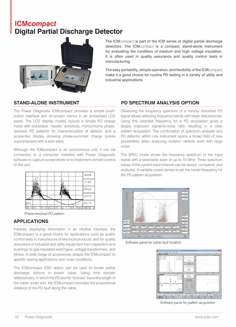
The ICMcompact is part of the ICM series of digital partial discharge detectors. The ICMcompact is a compact, stand-alone instrument for evaluating the condition of medium and high voltage insulation. It is often used in quality assurance and quality control tests in manufacturing.
The easy portability, simple operation, and flexibility of the ICMcompact make it a good choice for routine PD testing in a variety of utility and industrial applications.
STAND-ALONE INSTRUMENT PD SPECTRUM ANALYSIS OPTION
APPLICATIONS
The Power Diagnostix ICMcompact provides a simple push- button interface and on-screen menus in an embedded LCD panel. The LCD display modes include a simple PD charge meter with adjustable “needle” sensitivity, monochrome phase-resolved PD patterns for characterization of defects, and a scope-like display showing phase-summed charge pulses superimposed with a sine wave.
Although the ICMcompact is an autonomous unit, it can be connected to a computer installed with Power Diagnostix software to capture screenshots or to implement remote control of the unit.
Observing the frequency spectrum of a harshly disturbed PD signal allows selecting frequency bands with fewer disturbances. Using this selected frequency for a PD acquisition gives a largely improved signal-to-noise ratio resulting in a clear pattern acquisition. The combination of spectrum analyzer and PD detector within one instrument opens a broad field of new possibilities when analyzing isolation defects even with large noise.
The SPEC mode shows the frequency spectrum of the input signal with a selectable span of up to 10 MHz. Three spectrum traces of the current input channel can be stored, compared, and analyzed. A variable cursor serves to set the center frequency for the PD pattern acquisition.
Instantly displaying information in an intuitive interface, the ICMcompact is a good choice for applications such as quality control tests in manufacture of electrical products, and for quality assurance of industrial and utility equipment from capacitors and bushings to gas-insulated switchgear, voltage transformers, and others. A wide range of accessories adapts the ICMcompact to specific testing applications and noise conditions.
The ICMcompact DSO option can be used to locate partial discharge defects in power cable. Using time domain reflectometry, in which the PD and its “echoes” travel the length of the cable under test, the ICMcompact provides the proportional distance of the PD fault along the cable.
Phase-resolved PD pattern
Software panel for cable fault location
Software panel for pattern acquisition
www.pdix.com 17
AIAcompact Partial Discharge Measurement Device
EASY-TO-APPLY SUBSTATION CONDITION ASSESSMENT
SCOPE
METER
TIME
Acoustic partial discharge measurements can be easily applied on gas-insulated switchgear and other high voltage equip- ment without the need of interrupting the operation. Such online measurements help to identify internal imperfections of the insulation system, which may lead to breakdown and system failure in the future.
Acoustic partial discharge measurements rely on the close acoustic contact of the area producing the discharge to the point of access, where the sensor is placed. Most of the partial discharge activity in GIS offer such a good contact and, hence, can be detected at a good sensitivity.
Therefore, discharges from sharp points or cones as well as discharge activity from delaminations can be identified at a sensitivity, which is mostly comparable to the conventional electrical detection according to the IEC60270.
For some defect types, such as the so-called hopping or bouncing particles, the acoustic detection is by far superior to the electrical detection.
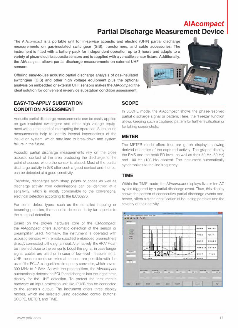
Based on the proven hardware core of the ICMcompact, the AIAcompact offers automatic detection of the sensor or preamplifier used. Normally, the instrument is operated with acoustic sensors with remote supplied embedded preamplifiers directly connected to the signal input. Alternatively, the RPA1F can be inserted close to the sensor to boost the signal, in case longer signal cables are used or in case of low-level measurements. UHF measurements on external sensors are possible with the use of the FCU2, a logarithmic frequency converter, which covers 300 MHz to 2 GHz. As with the preamplifiers, the AIAcompact automatically detects the FCU2 and changes into the logarithmic display for the UHF detection. To protect the instrument’s hardware an input protection unit like IPU2B can be connected to the sensor’s output. The instrument offers three display modes, which are selected using dedicated control buttons: SCOPE, METER, and TIME.
In SCOPE mode, the AIAcompact shows the phase-resolved partial discharge signal or pattern. Here, the ‘Freeze’ function allows keeping such a captured pattern for further evaluation or for taking screenshots.
The METER mode offers four bar graph displays showing derived quantities of the captured activity. The graphs display the RMS and the peak PD level, as well as their 50 Hz (60 Hz) and 100 Hz (120 Hz) content. The instrument automatically synchronizes to the line frequency.
Within the TIME mode, the AIAcompact displays five or ten AC cycles triggered by a partial discharge event. Thus, this display shows the pattern of consecutive partial discharge events and, hence, offers a clear identification of bouncing particles and the severity of their activity.
The AIAcompact is a portable unit for in-service acoustic and electric (UHF) partial discharge measurements on gas-insulated switchgear (GIS), transformers, and cable accessories. The instrument is fitted with a battery pack for independent operation up to 3 hours and adapts to a variety of piezo-electric acoustic sensors and is supplied with a versatile sensor fixture. Additionally, the AIAcompact allows partial discharge measurements on external UHF sensors.
Offering easy-to-use acoustic partial discharge analysis of gas-insulated switchgear (GIS) and other high voltage equipment plus the optional analysis on embedded or external UHF sensors makes the AIAcompact the ideal solution for convenient in-service substation condition assessment.
18 Power Diagnostix www.pdix.com
ICMflex Partial Discharge and Tan Delta Measurement System
The ICMflex high voltage instrument family offers inherent operator safety and greatly simplifies distribution class cable testing and other field tasks involving partial discharge detection, loss factor (tanδ) measurements, and PD fault location. It has been designed to simplify the application and to combine different measurement tasks with one instrument. With the unique concept of the ICMflex instruments, the entire acquisition hardware is placed on high voltage potential right at the position where the signals are. Thus, no signal cables are needed, as the instrument is fully self-contained and battery operated. In case that the instruments are used for measurements in an environment with high frequency (HF) disturbance, they can be equipped with a gating input for effective noise reduction. Every ICMflex instrument is fully remote controlled via Bluetooth or fiber optic communication. Using wireless Bluetooth or fiber optic technology the ICMflex tanδ and partial discharge analyzer family increases operator’s safety and greatly simplifies off-line testing and analysis of distribution class cables and rotating machine stator windings.
UNIQUE CONCEPT
OPTION TD
OPTION PD
OPTION LOC
The ICMflex instrument family is available with different options and for different voltage levels. Additionally, the self-contained ICMflex acquisition unit can be placed on top of any third-party coupling or reference capacitor. The option TD offers tanδ and power factor (PF) measurements. The option PD provides partial discharge measurements according to the IEC 60270, whereas the option LOC includes partial discharge location for power cables. Finally, the option TF covers a high voltage T-filter for sensitive partial discharge measurements to reduce disturbance signals from a high voltage supply.. The detachable Ni-MH battery provides more than eight hours of continuous operation, while a second battery can be charged. Any high voltage AC source can be used including resonant test sets and VLF high voltage sources.
Testing distribution-class cables in a field environment becomes an easy and inherently safe task. The ICMflex unit is simply placed between high voltage source and the cable to be tested – no further leads required. Thus, with one unit requiring only high voltage and ground connection all essential measurements on laid power cable are performed in one step: tanδ, partial discharge, and partial discharge location.
Off-line testing of generator and motor stator coils is simplified in the same way. Using any high voltage source, the critical AC measurements on the stator coil are done simultaneously: tanδ, PF, and partial discharge.
The tan delta analyzer uses an unbalanced bridge formed by internal shunt capacitors, the reference capacitor and the device under test. Here, the ICMflex software shows tanδ, PF, capacitance, voltage, and frequency.
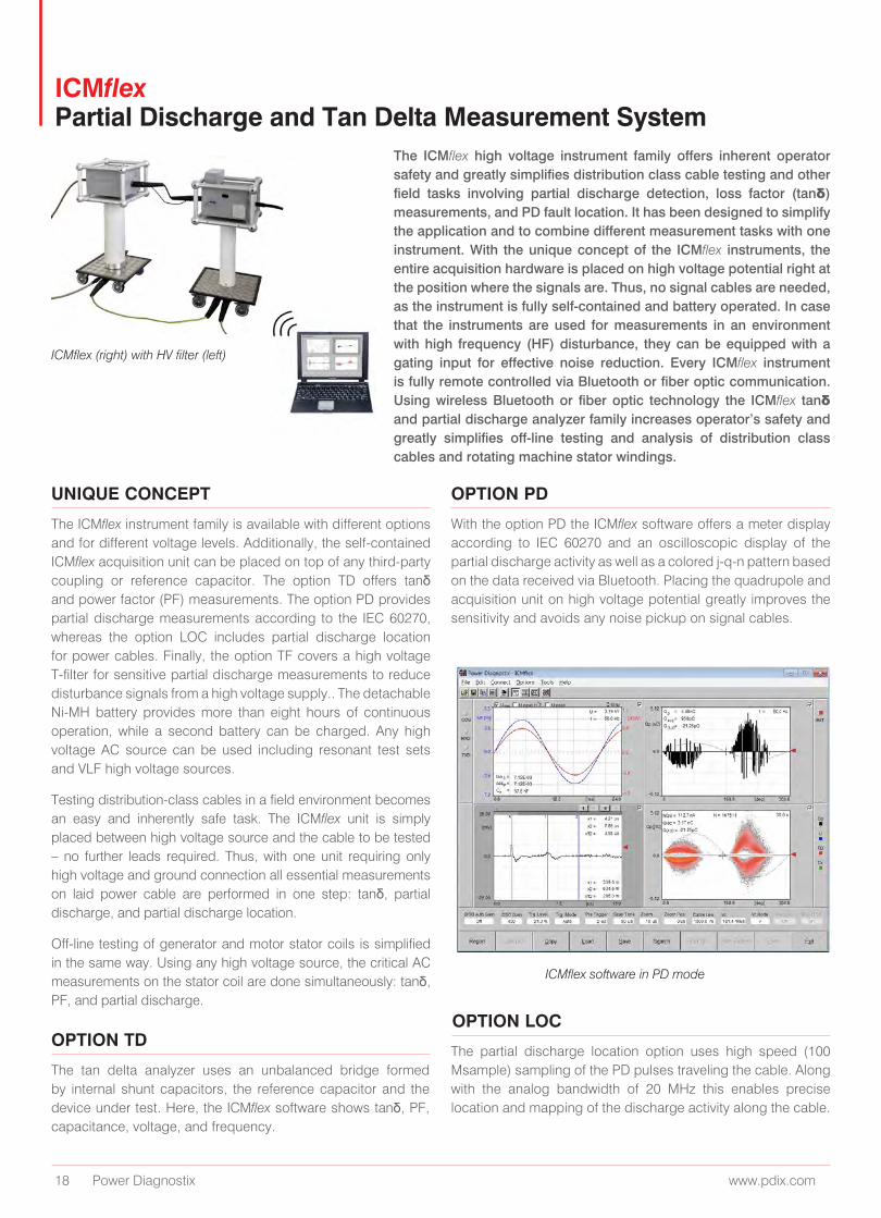
With the option PD the ICMflex software offers a meter display according to IEC 60270 and an oscilloscopic display of the partial discharge activity as well as a colored j-q-n pattern based on the data received via Bluetooth. Placing the quadrupole and acquisition unit on high voltage potential greatly improves the sensitivity and avoids any noise pickup on signal cables.
The partial discharge location option uses high speed (100 Msample) sampling of the PD pulses traveling the cable. Along with the analog bandwidth of 20 MHz this enables precise location and mapping of the discharge activity along the cable.
ICMflex (right) with HV filter (left)
ICMflex software in PD mode
www.pdix.com 19
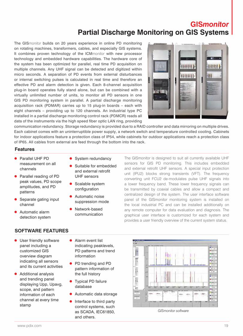
The GISmonitor builds on 20 years experience in online PD monitoring on rotating machines, transformers, cables, and especially GIS systems. It combines proven technology of the ICMmonitor with new processor technology and embedded hardware capabilities. The hardware core of the system has been optimized for parallel, real time PD acquisition on multiple channels. Any UHF signal can be detected and digitized within micro seconds. A separation of PD events from external disturbances or internal switching pulses is calculated in real time and therefore an effective PD and alarm detection is given. Each 8-channel acquisition plug-in board operates fully stand alone, but can be combined with a virtually unlimited number of units, to monitor all PD sensors in one GIS PD monitoring system in parallel. A partial discharge monitoring acquisition rack (PDMAR) carries up to 15 plug-in boards – each with eight channels – providing up to 120 channels. An industrial type PC installed in a partial discharge monitoring control rack (PDMCR) reads all data of the instruments via the high speed fiber optic LAN ring, providing
Features
SOFTWARE FEATURES
communication redundancy. Storage redundancy is provided due to a RAID controller and data mirroring on multiple drives. Each cabinet comes with an uninterruptible power supply, a network switch and temperature controlled cooling. Cabinets for indoor applications feature a protection class of IP54, while cabinets for outdoor applications reach a protection class of IP65. All cables from external are feed through the bottom into the rack.
The GISmonitor is designed to suit all currently available UHF sensors for GIS PD monitoring. This includes embedded and external retrofit UHF sensors. A special input protection unit (IPU2) blocks strong transients (VFT). The frequency converting unit FCU2 de-modulates pulse UHF signals into a lower frequency band. These lower frequency signals can be transmitted by coaxial cables and allow a compact and centralized design of the system. The user interface software panel of the GISmonitor monitoring system is installed on the local industrial PC and can be installed additionally on any remote computer for data evaluation and diagnosis. The graphical user interface is customized for each system and provides a user friendly overview of the current system status.
GISmonitor software
GISmonitor Partial Discharge Monitoring on GIS Systems
z Parallel UHF PD measurement on all channels
z Parallel reading of PD peak values, PD scope amplitudes, and PD patterns
z Separate gating input channel
z Automatic alarm detection system
z System redundancy
z Suitable for embedded and external retrofit UHF sensors
z Scalable system configuration
z Automatic noise suppression mode
z Network-based communication
z User friendly software panel including a customized GIS overview diagram indicating all sensors and its current activities
z Additional analysis and trending panel displaying Upp, Upavg, scope, and pattern information of each channel at every time stamp
z Alarm event list indicating peaklevels, PD patterns and trend information
z PD trending and PD pattern information of the full history
z Typical PD failure database
z Automatic data storage
z Interface to third party control systems, such as SCADA, IEC61850, and others.
20 Power Diagnostix www.pdix.com
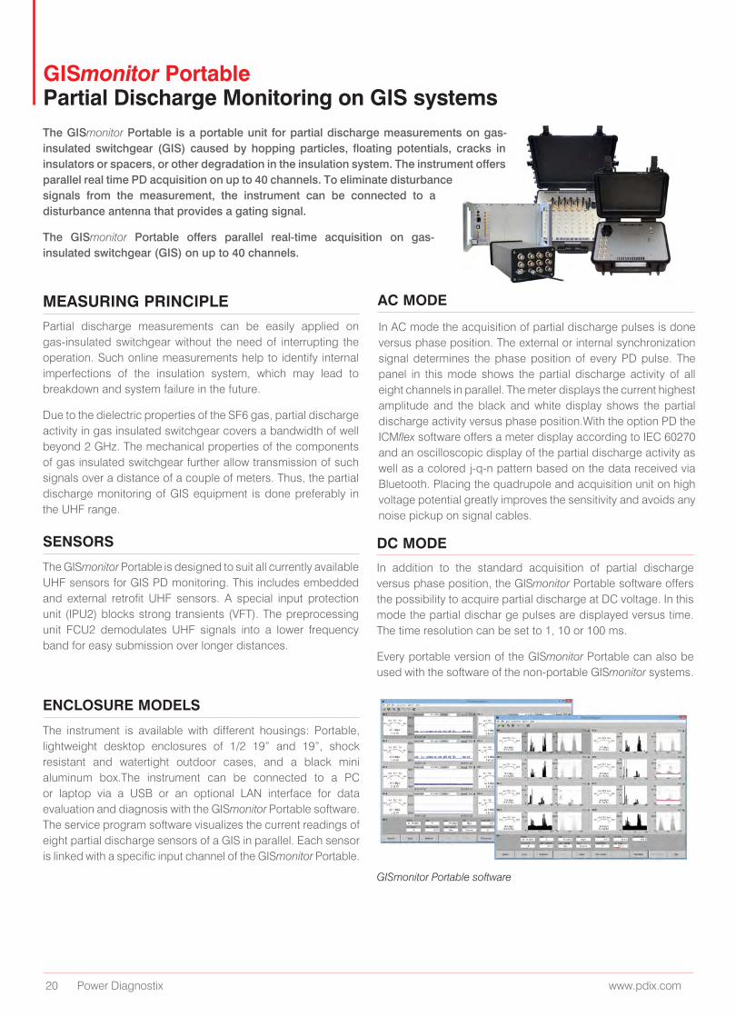
The GISmonitor Portable is a portable unit for partial discharge measurements on gas-insulated switchgear (GIS) caused by hopping particles, floating potentials, cracks in insulators or spacers, or other degradation in the insulation system. The instrument offers parallel real time PD acquisition on up to 40 channels. To eliminate disturbance signals from the measurement, the instrument can be connected to a disturbance antenna that provides a gating signal.
The GISmonitor Portable offers parallel real-time acquisition on gas-insulated switchgear (GIS) on up to 40 channels.
MEASURING PRINCIPLE
SENSORS
ENCLOSURE MODELS
AC MODE
DC MODE
Partial discharge measurements can be easily applied on gas-insulated switchgear without the need of interrupting the operation. Such online measurements help to identify internal imperfections of the insulation system, which may lead to breakdown and system failure in the future.
Due to the dielectric properties of the SF6 gas, partial discharge activity in gas insulated switchgear covers a bandwidth of well beyond 2 GHz. The mechanical properties of the components of gas insulated switchgear further allow transmission of such signals over a distance of a couple of meters. Thus, the partial discharge monitoring of GIS equipment is done preferably in the UHF range.
The GISmonitor Portable is designed to suit all currently available UHF sensors for GIS PD monitoring. This includes embedded and external retrofit UHF sensors. A special input protection unit (IPU2) blocks strong transients (VFT). The preprocessing unit FCU2 demodulates UHF signals into a lower frequency band for easy submission over longer distances.
The instrument is available with different housings: Portable, lightweight desktop enclosures of 1/2 19” and 19”, shock resistant and watertight outdoor cases, and a black mini aluminum box.The instrument can be connected to a PC or laptop via a USB or an optional LAN interface for data evaluation and diagnosis with the GISmonitor Portable software. The service program software visualizes the current readings of eight partial discharge sensors of a GIS in parallel. Each sensor is linked with a specific input channel of the GISmonitor Portable.
In addition to the standard acquisition of partial discharge versus phase position, the GISmonitor Portable software offers the possibility to acquire partial discharge at DC voltage. In this mode the partial dischar ge pulses are displayed versus time. The time resolution can be set to 1, 10 or 100 ms.
Every portable version of the GISmonitor Portable can also be used with the software of the non-portable GISmonitor systems.
In AC mode the acquisition of partial discharge pulses is done versus phase position. The external or internal synchronization signal determines the phase position of every PD pulse. The panel in this mode shows the partial discharge activity of all eight channels in parallel. The meter displays the current highest amplitude and the black and white display shows the partial discharge activity versus phase position.With the option PD the ICMflex software offers a meter display according to IEC 60270 and an oscilloscopic display of the partial discharge activity as well as a colored j-q-n pattern based on the data received via Bluetooth. Placing the quadrupole and acquisition unit on high voltage potential greatly improves the sensitivity and avoids any noise pickup on signal cables.
GISmonitor Portable software
GISmonitor Portable Partial Discharge Monitoring on GIS systems
www.pdix.com 21
ICMmonitor Portable Partial Discharge Monitoring Device
The ICMmonitor Portable is part of the Power Diagnostix ICM series of digital partial discharge detectors. It is a compact, stand-alone instrument for evaluating the condition of medium and high voltage insulation. A built-in four-, or eight-channel multiplexer offers scanning of three-phase systems or multiple sensors. It is used principally for permanent, continuous on-line monitoring of rotating machines, cable systems, power transformers, and gas-insulated switch gear (GIS).
The multifunctional ICMmonitor Portable, with its embedded display, convenient trending, and settable alarms, is an ideal solution for continuous on-line monitoring of rotating machines and other electric devices in industrial and utility applications.
EMBEDDED DISPLAY ALARMS AND TRENDING
SPECTRUM ANALYSIS
NOISE REJECTION
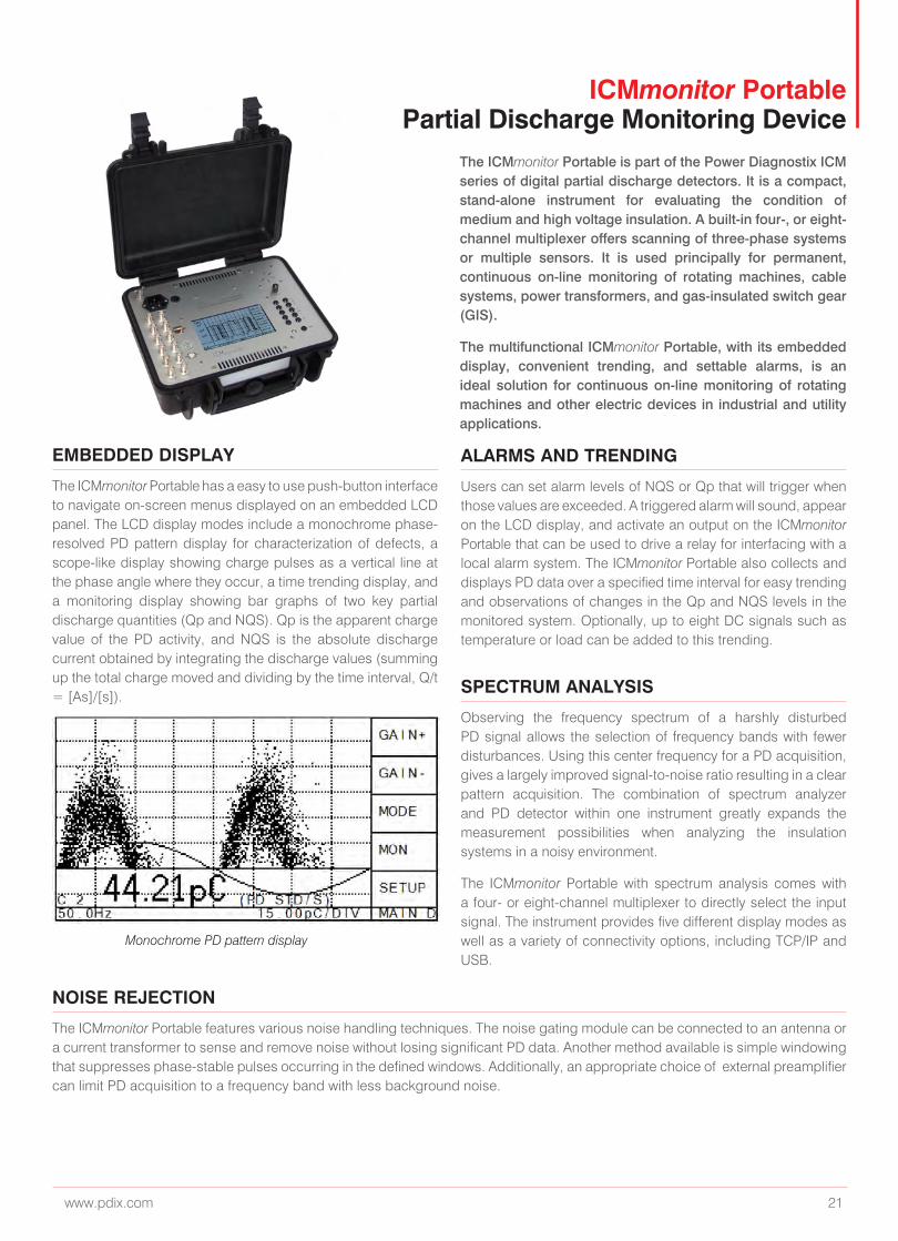
The ICMmonitor Portable has a easy to use push-button interface to navigate on-screen menus displayed on an embedded LCD panel. The LCD display modes include a monochrome phase-resolved PD pattern display for characterization of defects, a scope-like display showing charge pulses as a vertical line at the phase angle where they occur, a time trending display, and a monitoring display showing bar graphs of two key partial discharge quantities (Qp and NQS). Qp is the apparent charge value of the PD activity, and NQS is the absolute discharge current obtained by integrating the discharge values (summing up the total charge moved and dividing by the time interval, Q/t = [As]/[s]).
Users can set alarm levels of NQS or Qp that will trigger when those values are exceeded. A triggered alarm will sound, appear on the LCD display, and activate an output on the ICMmonitor Portable that can be used to drive a relay for interfacing with a local alarm system. The ICMmonitor Portable also collects and displays PD data over a specified time interval for easy trending and observations of changes in the Qp and NQS levels in the monitored system. Optionally, up to eight DC signals such as temperature or load can be added to this trending.
Observing the frequency spectrum of a harshly disturbed PD signal allows the selection of frequency bands with fewer disturbances. Using this center frequency for a PD acquisition, gives a largely improved signal-to-noise ratio resulting in a clear pattern acquisition. The combination of spectrum analyzer and PD detector within one instrument greatly expands the measurement possibilities when analyzing the insulation systems in a noisy environment.
The ICMmonitor Portable with spectrum analysis comes with a four- or eight-channel multiplexer to directly select the input signal. The instrument provides five different display modes as well as a variety of connectivity options, including TCP/IP and USB.
The ICMmonitor Portable features various noise handling techniques. The noise gating module can be connected to an antenna or a current transformer to sense and remove noise without losing significant PD data. Another method available is simple windowing that suppresses phase-stable pulses occurring in the defined windows. Additionally, an appropriate choice of external preamplifier can limit PD acquisition to a frequency band with less background noise.
Monochrome PD pattern display
22 Power Diagnostix www.pdix.com
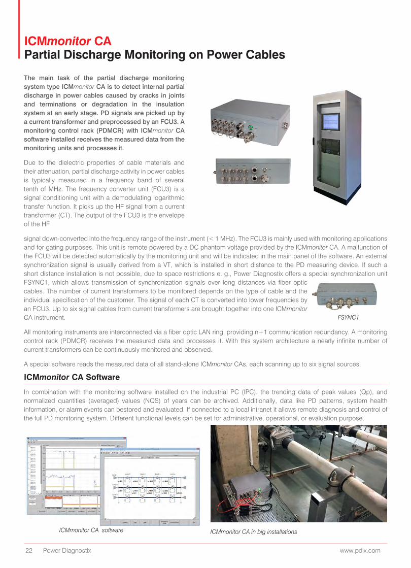
The main task of the partial discharge monitoring system type ICMmonitor CA is to detect internal partial discharge in power cables caused by cracks in joints and terminations or degradation in the insulation system at an early stage. PD signals are picked up by a current transformer and preprocessed by an FCU3. A monitoring control rack (PDMCR) with ICMmonitor CA software installed receives the measured data from the monitoring units and processes it.
Due to the dielectric properties of cable materials and their attenuation, partial discharge activity in power cables is typically measured in a frequency band of several tenth of MHz. The frequency converter unit (FCU3) is a signal conditioning unit with a demodulating logarithmic transfer function. It picks up the HF signal from a current transformer (CT). The output of the FCU3 is the envelope of the HF
signal down-converted into the frequency range of the instrument (< 1 MHz). The FCU3 is mainly used with monitoring applications and for gating purposes. This unit is remote powered by a DC phantom voltage provided by the ICMmonitor CA. A malfunction of the FCU3 will be detected automatically by the monitoring unit and will be indicated in the main panel of the software. An external synchronization signal is usually derived from a VT, which is installed in short distance to the PD measuring device. If such a short distance installation is not possible, due to space restrictions e. g., Power Diagnostix offers a special synchronization unit FSYNC1, which allows transmission of synchronization signals over long distances via fiber optic cables. The number of current transformers to be monitored depends on the type of cable and the individual specification of the customer. The signal of each CT is converted into lower frequencies by an FCU3. Up to six signal cables from current transformers are brought together into one ICMmonitor CA instrument.
All monitoring instruments are interconnected via a fiber optic LAN ring, providing n+1 communication redundancy. A monitoring control rack (PDMCR) receives the measured data and processes it. With this system architecture a nearly infinite number of current transformers can be continuously monitored and observed.
A special software reads the measured data of all stand-alone ICMmonitor CAs, each scanning up to six signal sources.
ICMmonitor CA Software
In combination with the monitoring software installed on the industrial PC (IPC), the trending data of peak values (Qp), and normalized quantities (averaged) values (NQS) of years can be archived. Additionally, data like PD patterns, system health information, or alarm events can bestored and evaluated. If connected to a local intranet it allows remote diagnosis and control of the full PD monitoring system. Different functional levels can be set for administrative, operational, or evaluation purpose.
ICMmonitor CA software ICMmonitor CA in big installations
FSYNC1
ICMmonitor CA Partial Discharge Monitoring on Power Cables
www.pdix.com 23
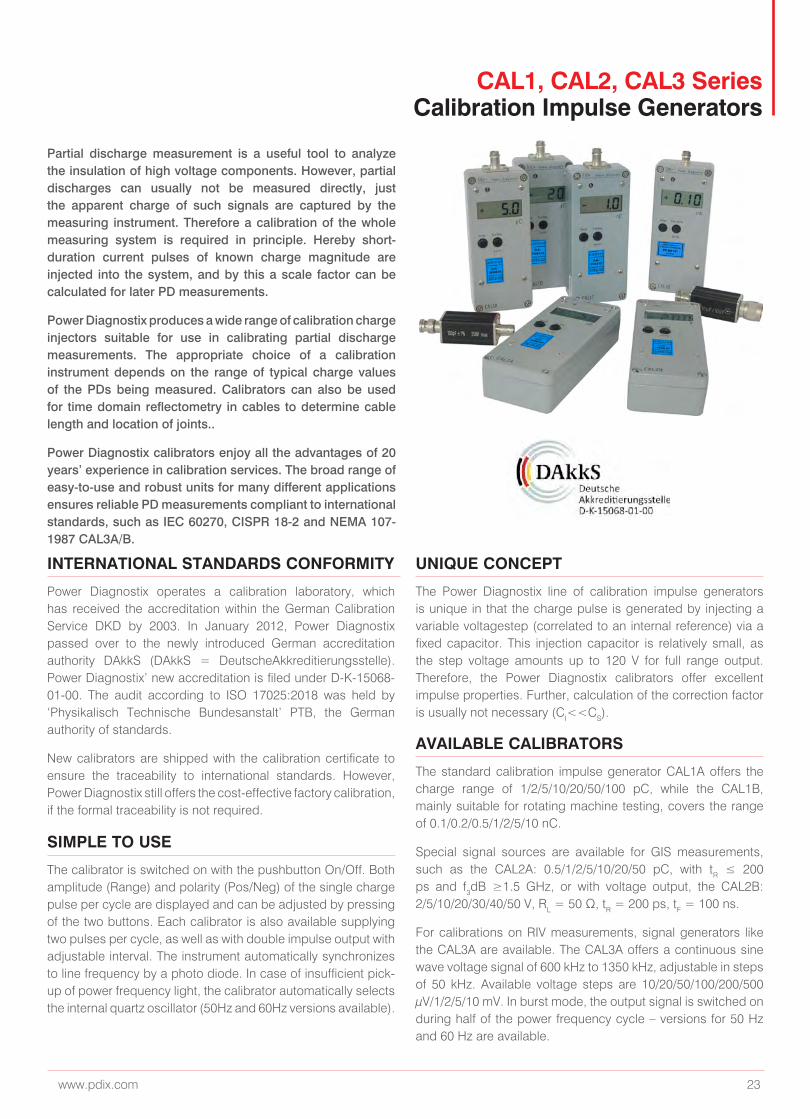
CAL1, CAL2, CAL3 Series Calibration Impulse Generators
INTERNATIONAL STANDARDS CONFORMITY UNIQUE CONCEPT
AVAILABLE CALIBRATORS
SIMPLE TO USE
Power Diagnostix operates a calibration laboratory, which has received the accreditation within the German Calibration Service DKD by 2003. In January 2012, Power Diagnostix passed over to the newly introduced German accreditation authority DAkkS (DAkkS = DeutscheAkkreditierungsstelle). Power Diagnostix’ new accreditation is filed under D-K-15068-01-00. The audit according to ISO 17025:2018 was held by ‘Physikalisch Technische Bundesanstalt’ PTB, the German authority of standards.
New calibrators are shipped with the calibration certificate to ensure the traceability to international standards. However, Power Diagnostix still offers the cost-effective factory calibration, if the formal traceability is not required.
The Power Diagnostix line of calibration impulse generators is unique in that the charge pulse is generated by injecting a variable voltagestep (correlated to an internal reference) via a fixed capacitor. This injection capacitor is relatively small, as the step voltage amounts up to 120 V for full range output. Therefore, the Power Diagnostix calibrators offer excellent impulse properties. Further, calculation of the correction factor is usually not necessary (CI<<CS).
The standard calibration impulse generator CAL1A offers the charge range of 1/2/5/10/20/50/100 pC, while the CAL1B, mainly suitable for rotating machine testing, covers the range of 0.1/0.2/0.5/1/2/5/10 nC.
Special signal sources are available for GIS measurements, such as the CAL2A: 0.5/1/2/5/10/20/50 pC, with tR ≤ 200 ps and f3dB ≥1.5 GHz, or with voltage output, the CAL2B: 2/5/10/20/30/40/50 V, RL = 50 Ω, tR = 200 ps, tF = 100 ns.
For calibrations on RIV measurements, signal generators like the CAL3A are available. The CAL3A offers a continuous sine wave voltage signal of 600 kHz to 1350 kHz, adjustable in steps of 50 kHz. Available voltage steps are 10/20/50/100/200/500 μV/1/2/5/10 mV. In burst mode, the output signal is switched on during half of the power frequency cycle – versions for 50 Hz and 60 Hz are available.
The calibrator is switched on with the pushbutton On/Off. Both amplitude (Range) and polarity (Pos/Neg) of the single charge pulse per cycle are displayed and can be adjusted by pressing of the two buttons. Each calibrator is also available supplying two pulses per cycle, as well as with double impulse output with adjustable interval. The instrument automatically synchronizes to line frequency by a photo diode. In case of insufficient pick-up of power frequency light, the calibrator automatically selects the internal quartz oscillator (50Hz and 60Hz versions available).
Partial discharge measurement is a useful tool to analyze the insulation of high voltage components. However, partial discharges can usually not be measured directly, just the apparent charge of such signals are captured by the measuring instrument. Therefore a calibration of the whole measuring system is required in principle. Hereby short-duration current pulses of known charge magnitude are injected into the system, and by this a scale factor can be calculated for later PD measurements.
Power Diagnostix produces a wide range of calibration charge injectors suitable for use in calibrating partial discharge measurements. The appropriate choice of a calibration instrument depends on the range of typical charge values of the PDs being measured. Calibrators can also be used for time domain reflectometry in cables to determine cable length and location of joints..
Power Diagnostix calibrators enjoy all the advantages of 20 years’ experience in calibration services. The broad range of easy-to-use and robust units for many different applications ensures reliable PD measurements compliant to international standards, such as IEC 60270, CISPR 18-2 and NEMA 107-1987 CAL3A/B.
24 Power Diagnostix www.pdix.com
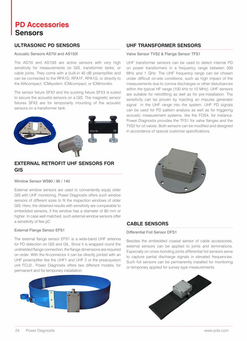
PD Accessories Sensors
ULTRASONIC PD SENSORS
EXTERNAL RETROFIT UHF SENSORS FOR GIS
CABLE SENSORS
UHF TRANSFORMER SENSORS
Acoustic Sensors AS75I and AS150I
The AS75I and AS150I are active sensors with very high sensitivity for measurements on GIS, transformer tanks, or cable joints. They come with a built-in 40 dB preamplifier and can be connected to the RPA1D, RPA1F, RPA1G, or directly to the AIAcompact, ICMsystem, ICMcompact, or ICMmonitor.
The sensor fixture SFX2 and the sucking fixture SFX3 is suited to secure the acoustis sensors on a GIS. The magnetic sensor fixtures SFX2 are for temporarily mounting of the acoustic sensors on a transformer tank.
Differential Foil Sensor DFS1
Besides the embedded coaxial sensor of cable accessories, external sensors can be applied to joints and terminations. Especially on cross-bonding joints differential foil sensors serve to capture partial discharge signals in elevated frequencies. Such foil sensors can be permanently installed for monitoring or temporary applied for survey type measurements.
Valve Sensor TVS2 & Flange Sensor TFS1
UHF transformer sensors can be used to detect internal PD on power transformers in a frequency range between 300 MHz and 1 GHz. The UHF frequency range can be chosen under difficult on-site conditions, such as high impact of the measurements due to corona discharges or other disturbances within the typical HF range (100 kHz to 10 MHz). UHF sensors are suitable for retrofitting as well as for pre-installation. The sensitivity can be proven by injecting an impulse generator signal in the UHF range into the system. UHF PD signals can be used for PD pattern analysis as well as for triggering acoustic measurement systems, like the FOS4, for instance. Power Diagnostix provides the TFS1 for valve flanges and the TVS2 for oil valves. Both sensors can be modified and designed in accordance of special customer specifications.
Window Sensor WS80 / 95 / 140
External window sensors are used to conveniently equip older GIS with UHF monitoring. Power Diagnostix offers such window sensors of different sizes to fit the inspection windows of older GIS. Here, the obtained results with sensitivity are comparable to embedded sensors, if the window has a diameter of 80 mm or higher. In case well matched, such external window sensors offer a sensitivity of few pC.
External Flange Sensor EFS1
The external flange sensor EFS1 is a wide-band UHF antenna for PD detection on GIS and GIL. Since it is wrapped round the unshielded flange connection, the flange dimensions are required on order. With the N-connector it can be directly jointed with an UHF preamplifier like the UHF1 and UHF 2 or the preacquision unit FCU2.. Power Diagnostix offers two different models, for permanent and for temporary installation.
www.pdix.com 25
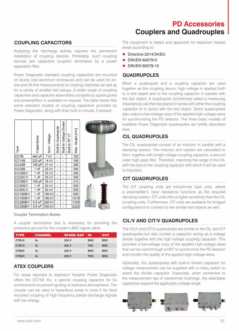
COUPLING CAPACITORS
QUADRUPOLES
CIL QUADRUPOLES
CIT QUADRUPOLES
CIL/V AND CIT/V QUADRUPOLES
Analyzing the discharge activity requires the permanent installation of coupling devices. Preferably, such coupling devices are capacitive couplers terminated by a power separation filter.
Power Diagnostix standard coupling capacitors are mounted on sturdy cast aluminum enclosures and can be used for on-line and off-line measurements on rotating machines as well as for a variety of smaller test setups. A wider range of coupling capacitors and capacitor assemblies complete by quadrupoles and preamplifiers is available on request. The table below lists some standard models of coupling capacitors provided by Power Diagnostix, along with their built-in circuits, if present.
When a quadrupole and a coupling capacitor are used together as the coupling device, high voltage is applied both to a test object and to the coupling capacitor in parallel with the test object. A quadrupole (sometimes called a measuring impedance) can then be placed in series with either the coupling capacitor or in series with the test object. Some quadrupoles also output a low-voltage copy of the applied high-voltage wave for synchronizing the PD detector. The three basic models of available Power Diagnostix quadrupoles are briefly described here.
The CIL quadrupoles consist of an inductor in parallel with a damping resistor. The inductor and resistor are calculated to form, together with a high-voltage coupling capacitor, a second order high pass filter. Therefore, matching the range of the CIL with the size of the coupling capacitor with which it will be used is important.
The CIT coupling units are transformer type units, where a preamplifier’s input resistance functions as the required damping resistor. CIT units offer a higher sensitivity than the CIL coupling units. Furthermore, CIT units are available for bridged configurations to connect to two similar test objects as well.
The CIL/V and CIT/V quadrupoles are similar to the CIL and CIT quadrupoles but also contain a capacitor acting as a voltage divider together with the high voltage coupling capacitor. This provides a low-voltage copy of the applied high-voltage wave that can be used through a HST to synchronize the PD detector and monitor the quality of the applied high-voltage wave.
Optionally, the quadrupoles with built-in divider capacitor for voltage measurement can be supplied with a rotary switch to select the divider capacitor. Especially, when connected to the measurement tap of transformer bushings, the selectable capacitors expand the applicable voltage range
For areas exposed to explosion hazards Power Diagnostix offers the CC15A /Ex, a special coupling capacitor for Ex environments to prevent igniting of explosive atmospheres. The coupler can be used in hazardous areas in zone 2 for fixed mounted coupling of high frequency partial discharge signals with low energy.
Coupler Termination Boxes
A coupler termination box is necessary for providing the protective ground for the coupler’s BNC signal cable.
PD Accessories Couplers and Quadrouples
TYPE CHANNEL SPARK GAP IN OUT
CTB1A 3x 350 V BNC BNC
CTB1C 3x 350 V TNC BNC
CTB2A 4x 350 V BNC BNC
CTB2C 4x 350 V TNC BNC
ATEX COUPLERS
The equipment is tested and approved for explosion hazard areas according to:
z Directive 2014/34/EU z DIN/EN 60079-0 z DIN/EN 60079-15
26 Power Diagnostix www.pdix.com
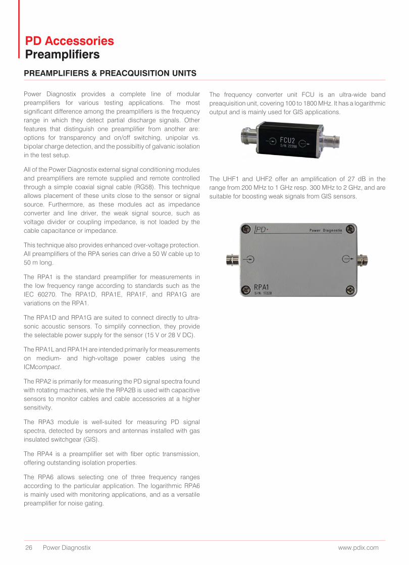
PD Accessories PreamplifiersPREAMPLIFIERS & PREACQUISITION UNITS
Power Diagnostix provides a complete line of modular preamplifiers for various testing applications. The most significant difference among the preamplifiers is the frequency range in which they detect partial discharge signals. Other features that distinguish one preamplifier from another are: options for transparency and on/off switching, unipolar vs. bipolar charge detection, and the possibiltiy of galvanic isolation in the test setup.
All of the Power Diagnostix external signal conditioning modules and preamplifiers are remote supplied and remote controlled through a simple coaxial signal cable (RG58). This technique allows placement of these units close to the sensor or signal source. Furthermore, as these modules act as impedance converter and line driver, the weak signal source, such as voltage divider or coupling impedance, is not loaded by the cable capacitance or impedance.
This technique also provides enhanced over-voltage protection. All preamplifiers of the RPA series can drive a 50 W cable up to 50 m long.
The RPA1 is the standard preamplifier for measurements in the low frequency range according to standards such as the IEC 60270. The RPA1D, RPA1E, RPA1F, and RPA1G are variations on the RPA1.
The RPA1D and RPA1G are suited to connect directly to ultra-sonic acoustic sensors. To simplify connection, they provide the selectable power supply for the sensor (15 V or 28 V DC).
The RPA1L and RPA1H are intended primarily for measurements on medium- and high-voltage power cables using the ICMcompact.
The RPA2 is primarily for measuring the PD signal spectra found with rotating machines, while the RPA2B is used with capacitive sensors to monitor cables and cable accessories at a higher sensitivity.
The RPA3 module is well-suited for measuring PD signal spectra, detected by sensors and antennas installed with gas insulated switchgear (GIS).
The RPA4 is a preamplifier set with fiber optic transmission, offering outstanding isolation properties.
The RPA6 allows selecting one of three frequency ranges according to the particular application. The logarithmic RPA6 is mainly used with monitoring applications, and as a versatile preamplifier for noise gating.
The frequency converter unit FCU is an ultra-wide band preaquisition unit, covering 100 to 1800 MHz. It has a logarithmic output and is mainly used for GIS applications.
The UHF1 and UHF2 offer an amplification of 27 dB in the range from 200 MHz to 1 GHz resp. 300 MHz to 2 GHz, and are suitable for boosting weak signals from GIS sensors.
www.pdix.com 27
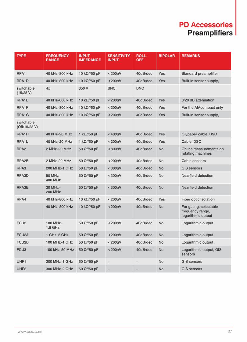
TYPE FREQUENCY RANGE
INPUT IMPEDANCE
SENSITIVITY INPUT
ROLL-OFF
BIPOLAR REMARKS
RPA1 40 kHz–800 kHz 10 kΩ//50 pF <200µV 40dB/dec Yes Standard preamplifier
RPA1D 40 kHz–800 kHz 10 kΩ//50 pF <200µV 40dB/dec Yes Built-in sensor supply,
switchable (15/28 V)
4x 350 V BNC BNC
RPA1E 40 kHz–800 kHz 10 kΩ//50 pF <200µV 40dB/dec Yes 0/20 dB attenuation
RPA1F 40 kHz–800 kHz 10 kΩ//50 pF <200µV 40dB/dec Yes For the AIAcompact only
RPA1G 40 kHz–800 kHz 10 kΩ//50 pF <200µV 40dB/dec Yes Built-in sensor supply,
switchable (Off/15/28 V)
RPA1H 40 kHz–20 MHz 1 kΩ//50 pF <400µV 40dB/dec Yes Oil/paper cable, DSO
RPA1L 40 kHz–20 MHz 1 kΩ//50 pF <200µV 40dB/dec Yes Cable, DSO
RPA2 2 MHz–20 MHz 50 Ω//50 pF <800µV 40dB/dec No Online measurements on rotating machines
RPA2B 2 MHz–20 MHz 50 Ω//50 pF <200µV 40dB/dec No Cable sensors
RPA3 200 MHz–1 GHz 50 Ω//50 pF <300µV 40dB/dec No GIS sensors
RPA3D 50 MHz–400 MHz
50 Ω//50 pF <300µV 40dB/dec No Nearfield detection
RPA3E 20 MHz–200 MHz
50 Ω//50 pF <300µV 40dB/dec No Nearfield detection
RPA4 40 kHz–800 kHz 10 kΩ//50 pF <200µV 40dB/dec Yes Fiber optic isolation
40 kHz–800 kHz 10 kΩ//50 pF <200µV 40dB/dec No For gating, selectable frequency range, logarithmic output
FCU2 100 MHz–1.8 GHz
50 Ω//50 pF <200µV 40dB/dec No Logarithmic output
FCU2A 1 GHz–2 GHz 50 Ω//50 pF <200µV 40dB/dec No Logarithmic output
FCU2B 100 MHz–1 GHz 50 Ω//50 pF <200µV 40dB/dec No Logarithmic output
FCU3 100 kHz–50 MHz 50 Ω//50 pF <200µV 40dB/dec No Logarithmic output, GIS sensors
UHF1 200 MHz–1 GHz 50 Ω//50 pF – – No GIS sensors
UHF2 300 MHz–2 GHz 50 Ω//50 pF – – No GIS sensors
PD Accessories Preamplifiers
www.pdix.com
PowerDiagnostix_SFV01
The word ‘Megger’ is a registered trademark. Copyright © 2020
Power Diagnostix Systems GmbHVaalser Strasse 250, 52074 Aachen, GermanyTel. +49 241 74927, Fax. +49 241 79521E-Mail: support(at)pdix.com