Embed Size (px)
Citation preview
IM800-06www.ueonline.com
800 SeriesIndicating Temperature Controls
Types 800, T800, 802
Please refer to IMT120 for Explosion Proof Types820E and 822E
UNITED ELECTR IC CONTROLS
Installation and Maintenance Instructions
IM800-06
GENERAL Temperature variations are sensed by a liquid filled sensing bulb which hydraulically transmits motion through a mechanism which rotates the indi-cating pointer and actuates precision snap-acting switch(es). Control set point(s) are varied by turning the external adjustment knob(s), according to procedures outlined (See Part II - Adjustments). Thermometer type T800 provides temperature indication only with no snap-acting switch.
MAXIMUM TEMPERATURE* STATED IN LITERATURE AND ON NAMEPLATE MUST NEVER BE EXCEEDED, EVEN BY SURGES IN THE SYSTEM. OCCASIONAL OPERATION OF UNIT UP TO MAX.
TEMPERATURE IS ACCEPTABLE (E.G., START-UP, TESTING). CONTINUOUS OPERATION SHOULD BE RESTRICTED TO THE DESIGNATED ADJUSTABLE RANGE.
Maximum Temperature - the highest temperature to which a sensing element may be occasionally operated at, without adversely affecting set point calibra-tion and repeatability.
Please refer to product bulletins for product specifications. Product bulletins may be found at www.ueonline.com.
Part I -InstallationTools Needed
Phillips screwdriver to secure customer supplied screws
5/64” Allen Wrench
INSTALL UNIT WHERE SHOCk, VIBRATION AND TEMPERATURE FLUC-TUATIONS ARE MINIMAL. DO NOT MOUNT UNIT IN AMBIENT TEMPERA-TURES EXCEEDING PUBLISHED LIMITS. ORIENT UNIT SO THAT MOIS-
TURE IS PREVENTED FROM ENTERING THE ENCLOSURE.
PREVENTATIVE MAINTENANCE / PERIODIC TESTING (6 MONTHS OR SOONER AS DICTATED BY THE ENVIRONMENT) IS NECESSARY TO ENSURE OPERATION OF THE PRODUCT TO SPECIFICATION. LUBRICATE ALL PIVOT POINTS AND
MOVING PARTS, TO PREVENT CORROSION, WITH COMPATIBLE DRY LUBRICANTS OR LIGHT GREASE.
When mounting 800 or 802 type controls, it may be necessary to remove adjustment knob and front cover. The knob is secured with a 5/64” Allen Setscrew. The cover is secured by four phillips screws at the corners.
MouNTINGThe controller may be mounted in any position to either a surface or panel
(1/4” thick maximum). Locate it where vibration, shock and ambient tempera-ture fluctuations are minimal. It is recommended that mounting the unit with the conduit connection on the top be avoided.
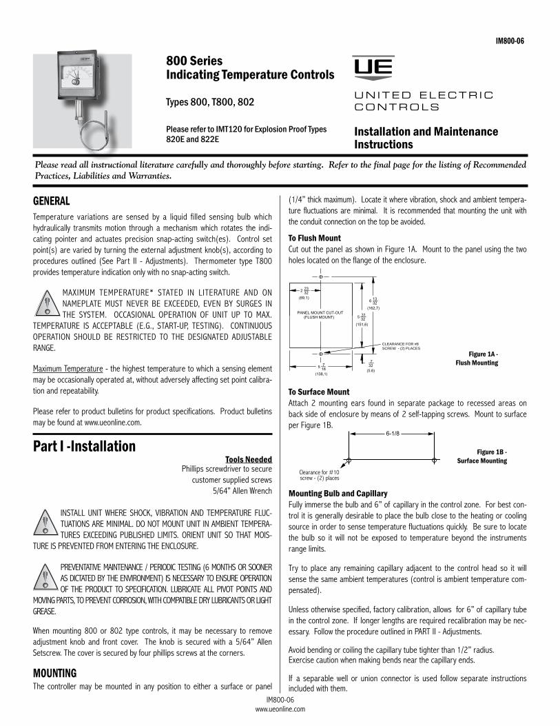
To Flush Mount Cut out the panel as shown in Figure 1A. Mount to the panel using the two holes located on the flange of the enclosure.
To Surface MountAttach 2 mounting ears found in separate package to recessed areas on back side of enclosure by means of 2 self-tapping screws. Mount to surface per Figure 1B.
Mounting Bulb and CapillaryFully immerse the bulb and 6” of capillary in the control zone. For best con-trol it is generally desirable to place the bulb close to the heating or cooling source in order to sense temperature fluctuations quickly. Be sure to locate the bulb so it will not be exposed to temperature beyond the instruments range limits.
Try to place any remaining capillary adjacent to the control head so it will sense the same ambient temperatures (control is ambient temperature com-pensated).
Unless otherwise specified, factory calibration, allows for 6” of capillary tube in the control zone. If longer lengths are required recalibration may be nec-essary. Follow the procedure outlined in PART II - Adjustments.
Avoid bending or coiling the capillary tube tighter than 1/2” radius.Exercise caution when making bends near the capillary ends.
If a separable well or union connector is used follow separate instructions included with them.
Please read all instructional literature carefully and thoroughly before starting. Refer to the final page for the listing of Recommended Practices, Liabilities and Warranties.
CLEARANCE FOR #8 SCREW - (2) PLACES
Figure 1A - Flush Mounting
Clearance for #10 screw - (2) places
Figure 1B - Surface Mounting

IM800-06www.ueonline.com
WIRING
DISCONNECT ALL SUPPLY CIRCUITS BEFORE WIRING. ELECTRICAL RATINGS STATED IN LITERATURE AND ON NAMEPLATE SHOULD NEVER BE EXCEEDED. OVERLOAD ON A SWITCH CAN CAUSE FAILURE
ON THE FIRST CYCLE. WIRE UNITS ACCORDING TO LOCAL AND NATIONAL ELECTRICAL CODES. MAXIMUM RECOMMENDED WIRE SIzE IS 14 AWG.
Types 800, 802Connect the electrical conduit to the case securing it with the grounding locknut supplied.
Note: Unless control is connected to a metallic conduit, grounding bushing should be removed from grounding wire. A separate conductor should be pro-vided from grounding system directly to the non-current carrying metal parts of control (splice the grounding wire).
Conduit opening is available on the left side as standard. It can be supplied on the right side on request. Wire through the 7/8” conduit hole directly to the lead-wire(s) provided, color coded as follows, or to the optional terminal block.
Switch 1 Switch 2
Common Violet YellowNormally Open Blue OrangeNormally Closed Black Red
See wiring Diagrams Figure 2A and 2B.
Part II - AdjustmentsTools Needed
5/64” Allen Wrench5/16” Open End Wrench (2 required)
Phillips and slotted tip screwdriver
Single Switch Type 800Move the set point Adjustment Pointer (red) up scale beyond the black Indicating Pointer. This permits checking the set point by moving the lever arm upward with a finger or tool simulating thermal assembly movement. Connect test lights to indicate switch operation or listen for the switch to click. Loosen adjustment “A” and move the Adjustment Pointer until it agrees with the Indicating Pointer. When the switch clicks re-tighten the screw.
Dual Switch Type 802Type 802 has a separate knob and pointer for each switch. Turn black knob for switch #2 and turn green inserted knob for switch #1. Set points are shown by individual pointers and may be separated up to 100% of dial range apart, so long as the red pointer is set higher than the green pointer.
To align either switch to the Adjustment Pointer the corresponding adjustment “A” must be loosened and the Adjustment Pointer set to the Indicating Pointer, then tighten adjustment “A”.
Note: Switch #1, green pointer, cannot be set to operate at a higher setting than switch #2, red pointer.
Connect test lights to indicate switch operation or listen for the individual switch clicks. The separation between switches is the difference between the high and low set points. The set points are determined by setting individual adjustment pointers and may be separated up to 100% of scale range apart.
Replace cover and adjustment knob if removed during installation. Controller is ready for operation. Turn setting pointer to desired control temperature and start up the process. To suit particular process conditions or for greater controller accuracy it may be desirable to make slight alterations to the set point or indicator reading. Procedures for making these adjustments are described below.
In-Process AdjustmentsUse an accurate test thermometer such as a thermocouple with its probe mounted directly to the center of the sensing bulb. Before making any adjustments, allow process temperature to stabilize; i.e., successive on-off cycles repeated.
Note: Prior to making any controller adjustments, the cover and adjustment knobs should be removed. The adjustment knob slides off adjustment shaft for all controls except the 802. The 802 requires a 5/64” allen wrench. When adjustments are completed, all applicable parts should be replaced.
Correct any difference between the Indicating Pointer and the test ther-mometer by holding the compensator with a 5/16” wrench while turning the zero adjustment “C” on the thermal assembly with a second 5/16” wrench, per Figure 3 until the brown Indicating Pointer reads the same as the test thermometer. Turning clockwise lowers indicated reading. Compare the pro-cess temperature with the set point Adjustment Pointer. Loosen adjustment screw “A” to align set point Adjustment Pointer with the Indicating Pointer. Re-tighten screw “A”.
N.C. N.O. COM.
N.C. N.O. COM.ORANGEREDYELLOWVIOLETBLUEBLACK
Figure 2A - Dual Switch
N.C. N.O. COM.
Plunger
BLUEBLACKVIOLET
Figure 2B - Single Switch
N.C. N.O. COM.
N.C. N.O.
BLUEBLACKVIOLETORANGEREDYELLOW
COM.
DUAL SWITCH
BLUEBLACKVIOLET
SINGLE SWITCH
N.C. N.O. COM.
Plunger
Figure 2C - Terminal Block option
Optional terminal block wiring is available for single or dual switch controls (option M100). See Figure 2C
(Refer to Figure 3)

IM800-06www.ueonline.com
Adjusting Thermometer Type T800Use the in-process adjustment to check the control. Differences between the test instrument and the thermometer can be corrected by turning the zero adjustment “C” per Figure 3 on the thermal assembly. Turning in lowers indicated reading.
Note: Indicating Pointer Deflection: The indicating pointers will read slightly low when the bulb temperature is 15° above the controller setting. This deflection is normal and repeatable (approximately 0.5% of scale range on single switch models) and is due to the transference of the switching mechanism load to the thermal system. It can be measured by moving the setting pointer from the high to the low end of the scale and observing the resultant indicating pointer deflection.
Correction of CapillaryIf the length of capillary immersed in the process differs from the amount immersed at the factory calibration bath, a calibration shift will occur. The error may be corrected as follows:
Move set pointer to the highest temperature setting. Note indicating scale reading with the head and sensor at room temperature. Loosen the two thermal assembly mounting screws. Re-position the housing index against the calibration on the instrument case (or skeleton casting) at a rate of 1 division line per capillary length listed in the following column. Move to the left if capillary is to be added to the process, or to the right if capillary is to be removed from process.
Model Number Range Cap Length/Division*
1 -180 to 120°F 2 ft
2 -125 to 350°F 1 1/2 ft
3 -125 to 500°F 1 ft
4 -40 to 120°F 4 ft
5 -40 to 180°F 3 ft
6 0 to 250°F 2 1/2 ft
7 0 to 400°F 2 ft
8 50 to 650°F 2 ft
* Added to or taken away from the process.
Tighten the two thermal assembly mounting screws. Note change indicated scale reading (if any).
Turn zero adjustment “C” to bring indicating pointer reading back to the origi-nal reading noted before. Turning in lowers indicated reading.
Note: The thermal assembly can be returned to its original position by align-ing its flange with the line scribed on the instrument case.
COMPENSATOR
SWITCH 1
SWITCH 2
Figure 3
Figure 4
Dimension AModel Inches mm
1BS 3-3/4 95.32BS 2-5/8 66.73BS 2-1/8 54.04BS 6-3/4 171.55BS 5 127.06BS 4-1/2 114.37BS 3 76.28BS 3-1/4 82.6
SET POINTADJUSTMENTPOINTER(RED)
Dimensions
General Layout

IM800-06www.ueonline.com
CP05111500
RECoMMENDED PRACTICES AND WARNINGS United Electric Controls Company recommends careful consideration of the following factors when specifying and installing UE pressure and temperature units. Before installing a unit, the Installation and Maintenance instructions provided with unit must be read and understood. • Toavoiddamagingunit,proofpressureandmaximumtemperature limitsstatedin literatureand
on nameplates must never be exceeded, even by surges in the system. Operation of the unit up to maximum pressure or temperature is acceptable on a limited basis (e.g., start-up, testing) but continuous operation must be restricted to the designated adjustable range. Excessive cycling at maximum pressure or temperature limits could reduce sensor life.
• Aback-upunit isnecessary forapplicationswheredamage toaprimaryunit couldendangerlife, limb or property. A high or low limit switch is necessary for applications where a dangerous runaway condition could result.
• Theadjustablerangemustbeselectedsothatincorrect,inadvertentormalicioussettingatanyrange point cannot result in an unsafe system condition.
• Installunitwhereshock,vibrationandambienttemperaturefluctuationswillnotdamageunitoraffect operation. Orient unit so that moisture does not enter the enclosure via the electrical con-nection. When appropriate, this entry point should be sealed to prevent moisture entry.
• Unitmustnotbealteredormodifiedaftershipment.ConsultUEif modificationisnecessary.• Monitor operation to observewarning signs of possible damage to unit, such as drift in set
point or faulty display. Check unit immediately.• Preventativemaintenanceandperiodictestingisnecessaryforcriticalapplicationswheredam-
age could endanger property or personnel.• Forallapplications,afactorysetunitshouldbetestedbeforeuse.• Electrical ratingsstated in literatureandonnameplatemustnotbeexceeded.Overloadona
switch can cause damage, even on the first cycle. Wire unit according to local and national electrical codes, using wire size recommended in installation sheet.
• Donotmountunitinambienttemp.exceedingpublishedlimits.
LIMITED WARRANTY
Seller warrants that the product hereby purchased is, upon delivery, free from defects in material and workmanship and that any such product which is found to be defective in such workmanship or mate-rial will be repaired or replaced by Seller (Ex-works, Factory, Watertown, Massachusetts. INCOTERMS); provided, however, that this warranty applies only to equipment found to be so defective within a period of 24 months from the date of manufacture by the Seller. Seller shall not be obligated under this war-ranty for alleged defects which examination discloses are due to tampering, misuse, neglect, improper storage, and in any case where products are disassembled by anyone other than authorized Seller’s representatives. EXCEPT FOR THE LIMITED WARRANTY OF REPAIR AND REPLACEMENT STATED ABOVE, SELLER DISCLAIMS ALL WARRANTIES WHATSOEVER WITH RESPECT TO THE PRODUCT, INCLUDING ALL IMPLIED WARRANTIES OF MERCHANTABILITY OR FITNESS FOR ANY PARTICULAR PURPOSE.
LIMITATIoN oF SELLER’S LIABILITY
Seller’s liability to Buyer for any loss or claim, including liability incurred in connection with (i) breach of any warranty whatsoever, expressed or implied, (ii) a breach of contract, (iii) a negligent act or acts (or negligent failure to act) committed by Seller, or (iv) an act for which strict liability will be inputted to seller, is limited to the “limited warranty” of repair and/or replacement as so stated in our warranty of product. In no event shall the Seller be liable for any special, indirect, consequential or other damages of a like general nature, including, without limitation, loss of profits or production, or loss or expenses of any nature incurred by the buyer or any third party.
UE specifications subject to change without notice.
U N I T E D E L E C T R I C C O N T R O L S
180 Dexter Avenue, P.O. Box 9143Watertown, MA 02471-9143 USATelephone: 617 926-1000 Fax: 617 926-2568http://www.ueonline.com