Embed Size (px)
Citation preview
Materials Testing Manual Part 7: Asphalt

Materials Testing Manual - Part 7, Transport and Main Roads, March 2016 1 of 1
Test Method Q301: Sampling of asphalt mix
This test shall be performed in accordance with AS 2891.1.1: Sampling – Loose asphalt.

Materials Testing Manual - Part 7, Transport and Main Roads, March 2016 1 of 1
Test Method Q302A: Dry coring of bound materials
This test shall be performed in accordance with AS 2891.1.2: Sampling – Coring method using the method described in Subsection 7.3.

Materials Testing Manual - Part 7, Transport and Main Roads, March 2016 1 of 1
Test Method Q302B: Wet coring of bound materials
This test shall be performed in accordance with AS 2891.1.2: Sampling – Coring method using the method described in Subsection 7.2.
Materials Testing Manual - Part 7, Transport and Main Roads, March 2016 1 of 2
Test Method Q303A: Preparation of asphalt core samples
1 Source
This method was developed in-house and applies techniques evolved through internal departmental research investigations.
2 Scope
This method describes the procedure for the preparation of asphalt core samples prior to testing. It involves cleaning, separation and sectioning of the core samples as appropriate.
3 Apparatus
The following apparatus is required:
3.1 Hammer and bolster (optional).
3.2 Masonry saw (optional).
3.3 Stiff wire brush.
3.4 Marking crayon.
4 Procedure
Prepare the core sample using either a hammer and bolster, or masonry saw as follows.
4.1 Hammer and bolster
4.1.1 Remove any base material, seal, tack coat or other foreign matter from the core sample using the hammer and bolster. Care must be taken when chipping to avoid damaging the sample.
4.1.2 Brush the top and bottom surfaces of the core sample with the wire brush to remove any remaining foreign matter and to expose fresh binder.
4.1.3 Where different asphalt layers within the core sample are required to be separated, perform the following procedure:
a) Place the bolster along the junction of the two layers and strike firmly with the hammer.
b) Rotate the sample through 180º and repeat Step 4.1.3 a).
c) Rotate the sample through 90º and repeat Step 4.1.3 a).
d) Repeat Steps 4.1.3 b) and 4.1.3 c) until the two layers are separated.
4.1.4 If required, air dry the core sample or core sample sections as appropriate to constant mass (Note 5.1).
4.1.5 Mark the core sample or core sample sections as appropriate with an identification number.
4.2 Masonry saw
4.2.1 Cut any base material, seal, tack coat or other foreign matter from the core sample using the masonry saw, ensuring that as much of the sample as possible remains (Notes 5.2, 5.3 and 5.4).
Test Method Q303A: Preparation of asphalt core samples
Materials Testing Manual - Part 7, Transport and Main Roads, March 2016 2 of 2
4.2.2 Where the core sample is required to be sectioned or where different asphalt layers within the core sample are required to be separated, perform the following procedure:
a) Cut the core sample at the required position(s) using the masonry saw (Notes 5.2 and 5.3).
b) Remove any loose material from the cut section(s) using the wire brush.
4.2.3 If required, air dry the core sample or core sample sections as appropriate to constant mass (Note 5.1).
4.2.4 Mark the core sample or core sample sections as appropriate with an identification number.
5 Notes on method
5.1 The core sample must be dry if the tests to be performed on it may be influenced by moisture content, for example, compacted density, voids properties. When air drying, a core sample is considered to have reached a constant mass when the difference between successive weighings, after a further 24 hours drying, is not more than 0.03 percent.
5.2 Where the cutting depth of the saw blade is smaller than the diameter of the core sample, the sample shall be rotated slowly during the cutting process.
5.3 Either water or dry ice can usually be used to cool the saw blade. Where the core sample is to be tested for properties which may be affected by water penetration into the sample, for example, compacted density, voids properties, cooling by dry ice is preferred. Otherwise, the core sample shall be air dried to constant mass in accordance with Note 5.1.
5.4 The intention is that all material not belonging to the asphalt layer is removed. This may result in the loss of some of the asphalt from the layer. Where measurement of layer thickness is required, such measurement will then need to be performed prior to cutting the core sample.
Materials Testing Manual - Part 7, Transport and Main Roads, November 2014 1 of 2
Test Method Q303B: Preparation of asphalt mix from a core sample
1 Source
This method was developed in-house using basic asphalt sampling principles and techniques evolved through internal departmental research investigations.
2 Scope
This method describes the procedure for obtaining a representative sample of the asphalt within a compacted asphalt pavement from a core sample taken from the pavement.
3 Apparatus
The following apparatus is required:
3.1 Oven, of suitable capacity, having a temperature of about 150ºC.
3.2 Sampling tube, rigid metal tube of 125 mm internal diameter having a bevelled or sharpened edge at one end and a length of about 200 mm.
3.3 Sample tray, a flat-bottomed tray of sufficient capacity to contain the mix comprising the asphalt core sample.
4 Procedure
The procedure shall be as follows:
4.1 Determine which of the top and bottom surfaces of the core sample has the greater surface texture and place the core sample on the sample tray with this surface downwards.
4.2 Place the sample tray containing the core sample in the oven.
4.3 Heat the core sample just sufficiently to allow ready separation of the mix particles without binder drainage or loss of shape (Note 5.1).
4.4 Remove the sample tray containing the softened but intact core sample from the oven.
4.5 Carefully position the bevelled or sharpened end of the sampling tube centrally against the upper surface of the core sample. With sufficient downward force and gentle rotation back and forth, carefully ease the sampling tube through the entire length of the core sample, progressively removing material on the outside of the tube and ensuring that:
a) if most of a particle is on the inside of the tube, the particle is included with the mix within the tube
b) if most of a particle is on the outside of the tube, the particle is included with the mix outside the tube, and
c) if a particle is bisected by the tube, the particle should be included with the mix either within the tube or outside the tube so that 50% of all such particles are included with the mix within the tube and 50% with the mix outside the tube.
4.6 Discard all mix outside the sampling tube.
4.7 Retain the mix within the sampling tube as a representative portion of the mix within the core sample.

Test Method Q303B: Preparation of asphalt mix from a core sample
Materials Testing Manual - Part 7, Transport and Main Roads, November 2014 2 of 2
5 Notes on method
5.1 The heating time will vary according to the sample dimensions. For 150 mm diameter core samples, a heating time of 15 to 30 minutes at 150ºC is usually adequate.
Materials Testing Manual - Part 7, Transport and Main Roads, November 2014 1 of 5
Test Method Q304A: Permeability of asphalt - ponding method
1 Source
This method was developed in-house using techniques evolved through internal departmental research investigations (Waters, T.J., “Permeability of Asphalt – Ponding Method”, Report TT306, 1999).
2 Scope
This method describes the procedure for the laboratory determination of the permeability of asphalt using the ponding method. It is applicable to cylindrical asphalt specimens of 100 mm or 150 mm diameter which have been either cored from the pavement or manufactured in the laboratory. It is restricted to asphalt having permeability values within the range of 0.1 to 3000 µm/s.
3 Apparatus
The following apparatus is required:
3.1 Balance of suitable capacity, with a resolution of at least 0.1 g and with a limit of performance within the range of ± 0.5 g.
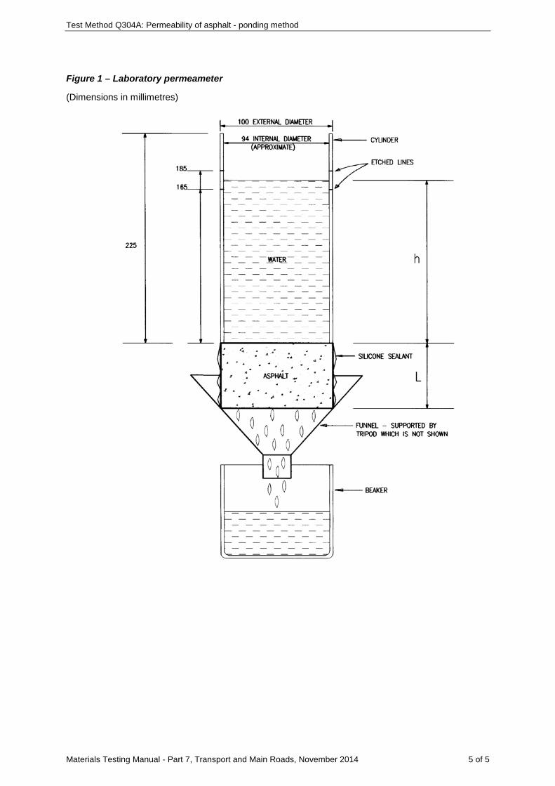
3.2 Laboratory permeameter, a clear perspex cylinder of known internal diameter having a wall thickness of about 3 mm and a length of 225 mm with etched measuring marks at 165 mm and 185 mm (Figure 1). The external diameter of the cylinder shall be either 100 mm or 150 mm, matching the diameter of the asphalt specimen.
3.3 Funnel, of appropriate dimensions to contain the asphalt specimen (Figure 1).
3.4 Tripod, of appropriate dimensions to support the collection funnel, sample and cylinder above the beaker.
3.5 Beaker, of 200 mL capacity.
3.6 Container, of 1 L capacity and fitted with a pouring lip.
3.7 Stopwatch or other suitable timing device, with a resolution not exceeding 0.1 seconds.
3.8 Spatula, to apply silicone sealant to the cylinder and sample.
3.9 Calliper, suitable for measuring the dimensions of the asphalt specimen, with a resolution not exceeding 0.1 mm and complying with AS 1984 or JIS B 7507.
4 Materials
4.1 Silicone sealant (Note 8.1).
5 Procedure
The procedure shall be as follows:
5.1 If the specimen is not dry or has been extracted using Test Method Q302B, air dry the specimen to constant mass (Note 8.2).
5.2 Measure the thickness of the specimen using the calliper at eight evenly distributed points around the perimeter and calculate the average thickness to the nearest 0.1 mm.
5.3 Measure the diameter of the specimen using the calliper at four evenly distributed points around the perimeter and calculate the average diameter to the nearest 0.1 mm.
Test Method Q304A: Permeability of asphalt - ponding method
Materials Testing Manual - Part 7, Transport and Main Roads, November 2014 2 of 5
5.4 Apply a thin layer of silicone sealant to completely seal the circumferential wall of the asphalt specimen.
5.5 Apply silicone sealant to the bottom edge of the cylinder and place the cylinder centrally on top of the specimen. Use additional sealant as required to seal the join between the cylinder and the specimen, ensuring that the sealant does not penetrate inside the cylinder.
5.6 Allow the silicone sealant to cure to a firm and tack-free state.
5.7 Position the funnel in the tripod and then seat the test specimen and attached cylinder in the funnel in an upright position.
5.8 Using the container, pour water into the cylinder until the water level is above 185 mm.
5.9 Allow the water to run through the specimen for 5 minutes or until the water level drops about 50 mm (Note 8.3).
5.10 Pour additional water into the cylinder until the water level is just above 185 mm.
5.11 Record the time taken for the water level to drop from 185 mm to 165 mm to the nearest 0.1 seconds.
5.12 Repeat Steps 5.10 to 5.11 twice (Notes 8.4 and 8.5).
6 Calculations
6.1 Calculate the average of the three time measurements to the nearest 0.1 seconds.
6.2 Calculate the volume of the cylinder between the 165 mm and 185 mm marks to the nearest 0.1 mL as follows:
2πDV=200
where V = volume of cylinder between 165 mm and 185 mm marks (mL)
D = internal diameter of cylinder (mm)
6.3 Calculate the flow rate as follows (Note 8.5):
VF=t
where F = flow rate (mL/s)
V = volume of cylinder between 165 mm and 185 mm marks (mL)
t = average time for water level to drop from 185 mm to 165 mm (s)
6.4 Calculate the effective head of water as follows (Note 8.5):
1 2e
h +hh =2
where eh = effective head (mm)
1h = initial head (mm)
2h = final head (mm)
Test Method Q304A: Permeability of asphalt - ponding method
Materials Testing Manual - Part 7, Transport and Main Roads, November 2014 3 of 5
In the usual case when the initial head is 185 mm and the final head is 165 mm, the effective head will be 175 mm.
6.5 Calculate the hydraulic gradient as follows:
eh +Li=L
where i = hydraulic gradient
eh = effective head (mm)
L = thickness of specimen (mm)
6.6 Calculate the cross-sectional area of the specimen as follows:
2-6s
sπDA = 10
4
where sA = cross-sectional area of specimen (m2)
sD = diameter of specimen (mm)
6.7 Calculate the permeability as follows:
s
Fk=A i
where k = permeability (µm/s)
F = flow rate (mL/s)
sA = cross-sectional area of specimen (m2)
i = hydraulic gradient
7 Reporting
Report the following values and general information:
7.1 Whether the sample is a core or a laboratory prepared specimen.
7.2 Test location including a longitudinal (chainage) and a lateral (offset) reference, where the sample is a core.
7.3 Mix and compaction details, where the sample is a laboratory prepared specimen.
7.4 Permeability to three significant figures (µm/s).
7.5 The permeability category and description (Table 1).
8 Notes on method
8.1 Before handling the silicone sealant, the operator must consult the relevant Safety Data Sheet (SDS).
8.2 A sample is considered to have reached a constant mass when the difference between successive weighings, after a further 24 hours air drying, is not more than 0.03 percent.
Test Method Q304A: Permeability of asphalt - ponding method
Materials Testing Manual - Part 7, Transport and Main Roads, November 2014 4 of 5
8.3 If there is no change in the water level after 5 minutes, omit Steps 5.10 to 5.12 and Clause 6, and record the permeability as 0 µm/s.
8.4 For asphalt of very low permeability (Table 1), a single time measurement will suffice and Steps 5.12 and 6.1 may be omitted.
8.5 Steps 5.10 to 5.12 provide a measure of the flow rate of water through the specimen. Where the flow rate is slow (say less than 0.05 mL/s), an alternative approach may be used involving a single measurement of the volume of water collected in a beaker positioned beneath the specimen over a specified time period. The effective head will then be the average of the initial and final head over the period when the water volume is collected beneath the specimen.
Table 1 – Permeability category and description
Permeability (µm/s) Category Description
0 - Impermeable
0.01 - 0.10 A1 Very low permeability
0.11 - 1.00 A2 Low permeability
1.00 - 10.0 B Moderately permeable
10.1 - 100 C Permeable
101 - 1000 D Moderately free draining
Test Method Q304A: Permeability of asphalt - ponding method
Materials Testing Manual - Part 7, Transport and Main Roads, November 2014 5 of 5
Figure 1 – Laboratory permeameter
(Dimensions in millimetres)
Materials Testing Manual - Part 7, Transport and Main Roads, September 2017 1 of 4
Test Method Q304B: Assessment of asphalt permeability
1 Source
This method was developed in-house but utilises test specimen preparation based on AS/NZS 2891.2.2: Sample preparation - Compaction of asphalt test specimens using a gyratory compactor, and permeability testing in accordance with Test Method Q304A.
2 Scope
This method sets out the procedure for determining the permeability of asphalt mix corresponding to a specific level of relative compaction. It involves establishing the relationship between permeability and air voids through permeability testing of asphalt test specimens prepared at three compaction levels using a gyratory compactor.
3 Apparatus
Where appropriate, the working tolerances of particular apparatus are contained in Table 1.
The following apparatus is required:
3.1 Gyratory compactor, capable of applying a vertical loading stress of 240 kPa to a test specimen in a mould at a rate of 60 rpm and at a fixed angle of 2° for 100 mm diameter specimens and 3° for 150 mm diameter specimens measured at the centre of the height of the mould. The compactor shall be fitted with the means for providing a continuous readout of test specimen height with the number of compaction cycles.
3.2 Specimen mould assembly, as described in AS/NZS 2891.2.2 for 100 mm and 150 mm diameter test specimens.
3.3 Wearing discs, steel discs of thickness 0.9 mm and diameter 99.8 mm or 149.8 mm as appropriate.
3.4 Specimen extractor, of suitable design to enable the test specimen to be removed intact from the mould.
3.5 Oven, thermostatically controlled at a temperature of 150°C.
3.6 Balance of a suitable capacity, having a resolution of at least 0.1 g and with a limit of performance within the range of ± 0.5 g.
3.7 Thermometer, a partial immersion thermometer or other suitable temperature measuring device having a temperature range which includes 150°C, and graduated to 1°C or less with an uncertainty of no more than 0.5°C.
3.8 Assorted mixing and handling apparatus, such as steel trays, trowels, spatulas and scoops.
4 Materials
4.1 Paper discs, having a diameter of about 100 mm.
4.2 Lubricant, suitable light oil for lubricating the paper discs (Note 8.1).
5 Procedure
The procedure shall be as follows:
5.1 Determine the maximum density of the mix in accordance with Test Method Q307A.
Test Method Q304B: Assessment of asphalt permeability
Materials Testing Manual - Part 7, Transport and Main Roads, September 2017 2 of 4
5.2 Select a target relative compaction level of 91% as determined in accordance with Test Method Q314.
5.3 Select the appropriate specimen mould assembly for the particular mix nominal size and place it in the oven for a period of at least 1 hour.
5.4 Remove the mould assembly from the oven and position a lubricated paper disc on the lower wearing disc in the mould.
5.5 Using the maximum density of the mix, the dimensions of the mould assembly and the test specimen height relevant to the mix nominal size in Table 2, estimate the quantity of mix required to provide the target relative compaction level.
5.6 Transfer this quantity of mix into the mould and return the mould assembly to the oven for 60 ± 10 minutes.
5.7 Remove the mould assembly from the oven, place a thermometer in the mix and measure the temperature. Provided that the temperature is within 150 ± 3°C, level the mix in the mould and place a lubricated paper disc on the mix surface (Note 8.2).
5.8 Place the upper wearing disc and top platen on the mix in the mould, position the mould assembly in the gyratory compactor and lock the mould assembly in place.
5.9 Compact the mix in the mould assembly until the test specimen height relevant to the mix nominal size in Table 2 is reached.
5.10 Remove the mould assembly from the gyratory compactor and take off the upper platen.
5.11 Allow the mould to cool sufficiently in air and then remove the test specimen from the mould using the specimen extractor, while ensuring the test specimen remains intact and shows no deformation.
5.12 Determine the compacted density and air voids of the test specimen in accordance with Test Method Q306C and Test Method Q311 respectively.
5.13 Repeat Steps 5.3 to 5.12 until three test specimens are prepared having an air voids of 9 ± 1%.
5.14 Repeat Steps 5.3 to 5.12 using a target compaction level of 93% until three test specimens are prepared having an air voids of 7 ± 1%.
5.15 Repeat Steps 5.3 to 5.12 using a target compaction level of 95% until three test specimens are prepared having an air voids of 5 ± 1%.
5.16 Remove the silicone sealant from each of the nine test specimens and determine the permeability of each in accordance with Test Method Q304A.
5.17 If any of the nine test specimens is determined to be impermeable or have a very low permeability as defined in Test Method Q304A, it shall not be accepted for the assessment of asphalt permeability. In this case, prepare a replacement test specimen using an appropriate lower relative compaction as described in Steps 5.3 to 5.12, and test its permeability as described in Step 5.16.
6 Calculations
6.1 Using the permeability and air voids results for each test specimen, determine the linear regression relationship between log permeability and air voids.
6.2 Accept the relationship determined in Step 6.1 provided that its coefficient of determination (r²) satisfies the relevant minimum value of Table 3. Otherwise, test additional test specimens
Test Method Q304B: Assessment of asphalt permeability
Materials Testing Manual - Part 7, Transport and Main Roads, September 2017 3 of 4
prepared at appropriate air voids within the range of 5 to 9%, as described in Steps 5.3 to 5.12 and 5.16 to 6.1, until the requirements of Table 3 are met.
6.3 Where required, calculate the permeability value corresponding to a specific value of air voids from this relationship.
7 Reporting
Report the following:
7.1 The air voids and permeability test results for each test specimen.
7.2 The linear regression relationship between log permeability and air voids.
7.3 Where required, the permeability value corresponding to a specific value of air voids to the nearest 1 µm/s.
8 Notes on method
8.1 Before handling the oil, the operator must consult the relevant Safety Data Sheet (SDS).
8.2 If the temperature of the mix falls below the compaction temperature range, the mix may be reheated. This will involve returning the mould assembly containing the mix to the oven until it reaches oven temperature and then repeating Step 5.7.
Table 1 - Specifications and working tolerances of apparatus
Item Unit Value Working tolerance
Gyratory compactor
Load application rate rpm 60 ± 5
Wearing disk
Diameter mm 99.8 or 149.8 ± 0.1
Thickness mm 0.9 ± 0.02
Oven
Temperature ºC 150 ± 5
Table 2 - Test specimen height
Mix nominal size Unit Value Working tolerance
DG14 mm 50 ± 2
DG20 mm 65 ± 2
DG28 mm 90 ± 2

Test Method Q304B: Assessment of asphalt permeability
Materials Testing Manual - Part 7, Transport and Main Roads, September 2017 4 of 4
Table 3 - Coefficient of determination (r²) minimum values
Number of test results
Minimum value Number of test results
Minimum value
9 0.636 15 0.411
10 0.585 16 0.388
11 0.540 17 0.367
12 0.501 18 0.348
13 0.467 19 0.331
14 0.437 20 0.315
Materials Testing Manual - Part 7, Transport and Main Roads, March 2016 1 of 8
Test Method Q305: Stability, flow and stiffness of asphalt - Marshall
1 Source
This method is based on AS 2891.5: Determination of stability and flow - Marshall Procedure. It differs from this Australian Standard by extending the range of asphalt mixes tested with companion alterations to test specimen preparation, apparatus requirements and some other procedural variations.
2 Scope
This method sets out the procedure for preparing test specimens of freshly mixed asphalt (either produced in the laboratory or at a mixing plant) by the Marshall procedure and determining stability, flow and stiffness values of the specimens using the Marshall apparatus. It is applicable to asphalt mixes not exceeding 28 mm nominal size.
3 Apparatus
Where appropriate, the working tolerances of particular apparatus are contained in Tables 1, 2, 5 and Figure 1.
The following apparatus is required:
3.1 Specimen mould assembly, consisting of the following:
3.1.1 For asphalt of nominal mix size ≤ 20 mm, a cylindrical steel or brass compaction mould having an internal diameter of 101.6 mm, a height of 89 mm and a thickness of 6 mm; a mould base with a thickness of 18 mm and an extension collar having an internal diameter of 101.6 mm, a height of 70 mm and a thickness of 6 mm.
3.1.2 For asphalt of nominal mix size > 20 mm, a cylindrical steel or brass compaction mould having an internal diameter of 150.0 mm, a height of 89 mm and a thickness of 8 mm; a mould base with a thickness of 18 mm and an extension collar having an internal diameter of 150.0 mm, a height of 70 mm and a thickness of 8 mm.
3.2 Hand compaction hammer, consisting of the following:
3.2.1 For asphalt of nominal mix size ≤ 20 mm, a flat circular tamping face having a diameter of 98.5 mm, and a sliding weight with a mass of 4.53 kg and a free fall of 457 mm (Notes 9.1, 9.2 and 9.3).
3.2.2 For asphalt of nominal mix size > 20 mm, a flat circular tamping face having a diameter of 149.0 mm, and a sliding weight with a mass of 9.92 kg and a free fall of 460 mm (Notes 9.1, 9.2 and 9.3).
3.3 Hand compaction pedestal, consisting of the following:
3.3.1 For asphalt of nominal mix size ≤ 20 mm, a wooden block, of approximate dimensions 200 mm square and 450 mm thick, capped by a steel plate of approximate dimensions 300 mm square and 25 mm thick. The air dry density of the wooden block shall be 720 kg/m3. The plate shall be securely attached to the block which shall be secured to a solid concrete floor or slab. Suitable guides for restraining the compaction mould and locating the compaction hammer centrally during compaction may be attached to the block.
3.3.2 For asphalt of nominal mix size > 20 mm:
a) a wooden block as described in Step 3.3.1, or
Test Method Q305: Stability, flow and stiffness of asphalt - Marshall
Materials Testing Manual - Part 7, Transport and Main Roads, March 2016 2 of 8
b) a concrete block, of approximate dimensions 360 mm square and 610 mm thick. Suitable guides for restraining the compaction mould and locating the compaction hammer centrally during compaction may be attached to the block.
3.4 Specimen extrusion jack, consisting of a hydraulic jack fitted with a plate on the ram and located within a metal frame. The dimensions of the plate shall be 100 mm diameter and 6 mm thick for 101.6 mm test specimens, and 148 mm diameter and 12 mm thick for 150 mm diameter test specimens. The frame shall retain the mould during extrusion of a test specimen.
3.5 Breaking head, consisting of upper and lower cylindrical segments each having an accurately machined inside cylinder face. The lower segment shall be mounted on a base having two perpendicular guide pins extending upwards. Guide bushes on the upper segment shall be located to direct the segments together without binding or loose motion on the guide pins.
3.6 Marshall testing machine, gear driven at a constant speed to give a rate of travel on the platen of 51 mm/min when the force is being applied, and capable of applying forces up to at least 22 kN. The machine shall be fitted with one of the following measurement systems (Note 9.4):
3.6.1 An elastic proving ring and two flow gauges. The proving ring shall be inserted between the breaking head and the loading beam or crosshead to measure the force on the test specimen. It shall have a capacity of at least 22 kN with a resolution of at least 0.002 mm and complying with a Class A device for forces up to 4.5 kN and complying with a Class B device for forces between 4.5 kN and its maximum loading. The flow gauges shall be placed on the guide pins of the breaking head and shall be capable of measuring the vertical deformation of the test specimen from the onset of load. The gauges shall have a scale interval of no more than 0.1 mm.
3.6.2 A load cell and transducer and appropriate continuous recording device of a capacity and accuracy at least equivalent to that of the proving ring and flow gauges described in Step 3.6.1.
3.7 Water bath, mechanically agitated and maintained at a temperature of 60ºC. The bath shall be at least 150 mm deep and shall be fitted with a perforated shelf about 50 mm from the bottom.
3.8 Oven, thermostatically controlled at an operating temperature corresponding to the appropriate compaction temperature specified in Table 3.
3.9 Hotplate, suitable for heating the mixing apparatus.
3.10 Balance of suitable capacity, with a resolution of at least 0.1 g and with a limit of performance within the range of ± 0.5 g.
3.11 Thermometer, a partial immersion thermometer or other suitable temperature measuring device having a temperature range which includes the appropriate range of Table 3, and graduated to 1ºC or less with an uncertainty of no more than 0.5ºC.
3.12 Measuring device, suitable for the measurement of the height of test specimens and with a resolution not exceeding 1 mm.
3.13 Marker.
3.14 Mixing apparatus, such as steel tray, steel trowel, spatulas and scoop.
4 Materials
The following materials are required:
4.1 Lubricant, suitable grease or viscous oil for lubricating the compaction moulds (Note 9.5).
Test Method Q305: Stability, flow and stiffness of asphalt - Marshall
Materials Testing Manual - Part 7, Transport and Main Roads, March 2016 3 of 8
4.2 Paper segments, of sufficient size to cover the mould base.
5 Preparation
Perform the following for each test specimen to be prepared:
5.1 Bring the oven to an operating temperature corresponding to the compaction temperature specified for the binder and asphalt type in Table 3.
5.2 Assemble the compaction mould (Note 9.6).
5.3 Place the compaction mould in the oven for approximately 1 hour.
5.4 Place the appropriate mixing apparatus on the hotplate.
5.5 Using the expected compacted density for the mix, calculate the required mass of the mix for the compaction mould to give the desired specimen height of 63.5 mm (Note 9.7).
5.6 Prepare the mix in accordance with Subsection 4.2 of Test Method Q301.
5.7 Remove the compaction mould from the oven and position a paper segment on the base within the mould.
5.8 Transfer the mix into the mould and level the surface of the mix, taking care to avoid segregation.
5.9 Place the mould in the oven for 60 ± 5 minutes.
5.10 Remove the mould from the oven and measure the mix temperature (Note 9.8). Provided that the temperature of the mix is within the compaction temperature range specified in Table 3, position a paper segment on the surface of the mix (Note 9.9).
5.11 Transfer the compaction mould to the compaction pedestal and compact the mix using the specified number of blows of the compaction hammer at a rate of 60 to 70 blows per minute with the hammer axis held vertically (Notes 9.2 and 9.10).
5.12 Remove the collar and base, and reassemble the compaction mould with the test specimen inverted (Note 9.11).
5.13 Compact the mix further using the specified number of blows of the compaction hammer at a rate of 60 to 70 blows per minute (Notes 9.2 and 9.10).
5.14 Remove the collar and base plate from the compaction mould and paper segments from the test specimen (where relevant), and mark the face of the test specimen clearly with an identification number (Note 9.12).
5.15 Allow the mould to cool in air and then extrude the test specimen.
6 Testing of specimens
6.1 Remove any lip formed around the edges of each test specimen without damage to the test specimen.
6.2 Measure the height of each test specimen at four points evenly spaced around the specimen and calculate the average height to the nearest 1 mm. Discard any test specimen having an average height outside the range of 57 to 70 mm (Note 9.13).
6.3 Clean the inside surfaces of the breaking head and lightly grease the guide pins.
6.4 Place the breaking head segments (where practicable) and test specimens in the water bath for 30 to 40 minutes.
Test Method Q305: Stability, flow and stiffness of asphalt - Marshall
Materials Testing Manual - Part 7, Transport and Main Roads, March 2016 4 of 8
6.5 Remove the breaking head segments from the water bath (where relevant) and complete Steps 6.6 and 6.7 within 30 seconds (Note 9.14).
6.6 Remove a test specimen from the water bath and place it centrally on its side in the lower segment of the breaking head. Place the upper segment of the breaking head on the test specimen and place the complete assembly centrally on the Marshall testing machine.
6.7 Zero the measurement system, start the Marshall testing machine and perform the test as follows:
6.7.1 For the proving ring and flow gauge system, apply the load until shear failure causes the proving ring dial gauge reading to decrease. Remove the flow gauges immediately from the breaking head and record the dial gauge reading to the nearest division and the flow gauge readings to the nearest 0.1 mm.
6.7.2 For the load cell and transducer system, where there is provision to capture and review load cell and transducer readings at specific time intervals, perform the following:
a) Apply the load and record load cell and transducer readings at intervals of 0.01 s until shear failure causes the load cell reading to decrease.
b) Determine the first four successive load cell readings where:
i. the range of the four readings does not exceed 0.1 kN, or
ii. the range of the four readings exceeds 0.1 kN but the fourth reading is lower than the first reading.
c) Record the first of these four successive readings as the test load cell reading.
d) Determine the transducer reading corresponding to the test load cell reading, adjust it for any seating error and record the adjusted reading as the test transducer reading.
6.7.3 For the load cell and transducer system, where there is no provision to capture and review load cell and transducer readings at specific time intervals, apply the load until shear failure causes the load cell reading to decrease. Record the load cell and transducer readings corresponding to the maximum load cell reading (Note 9.15).
6.8 Repeat Steps 6.6 and 6.7 for each of the remaining test specimens.
7 Calculations
7.1 Stability
7.1.1 Calculate the load (L) applied to each test specimen at shear failure to the nearest 0.1 kN using as appropriate:
a) the recorded dial gauge reading and the calibration relationship for the proving ring as determined in Step 6.7.1, or
b) the test load cell reading as determined in Step 6.7.2.
7.1.2 Calculate the stability of each test specimen to the nearest 0.1 kN as follows:
S=LF
where S = stability of test specimen (kN)
L = load at shear failure (kN)
F = correction factor of Table 4 according to the height of the test specimen
Test Method Q305: Stability, flow and stiffness of asphalt - Marshall
Materials Testing Manual - Part 7, Transport and Main Roads, March 2016 5 of 8
7.1.3 Calculate the stability of the asphalt as the average of the test specimen stability values to the nearest 0.1 kN.
7.2 Flow
7.2.1 Calculate the flow of each test specimen at shear failure to the nearest 0.1 mm using as appropriate:
a) the average of the two flow gauge readings recorded in Step 6.7.1, or
b) the test transducer reading as determined in Step 6.7.2.
7.2.2 Calculate the flow of the asphalt as the average of the test specimen flow values to the nearest 0.1 mm.
7.3 Stiffness
Calculate the stiffness of the asphalt to the nearest 0.1 kN/mm as follows:
stability of the asphaltStiffness flow of the asphalt
=
8 Reporting
Report the following:
8.1 Stability to the nearest 0.1 kN.
8.2 Flow to the nearest 0.1 mm.
8.3 Stiffness to the nearest 0.1 kN/mm.
8.4 The number of blows applied to each face of the test specimens during compaction.
9 Notes on method
9.1 Where a mechanical compactor is used instead of the hand compactor, the mass, free fall and design of the hammer foot should be identical to those of the hand compaction hammer and the automatic compactor should be securely anchored to a concrete base.
9.2 Where a mechanical compactor is used, it should be calibrated against hand compaction to determine the number of blows equivalent to the specified number of blows of hand compaction. Calibration checks should be performed on a regular basis and the difference between the density results obtained using the mechanical and hand compaction method should be no greater than 0.01 t/m3. Calibration should be conducted using quartered samples of the mix.
9.3 To ensure free fall of the weight is maintained, the shaft of the hammer should be thoroughly cleaned and dried after each set of compaction blows.
9.4 The apparatus described in Step 3.6.1 is unsuitable for testing stone mastic asphalt and that described in Step 3.6.2 must be used for this purpose.
9.5 Before handling the lubricant, the operator must consult the relevant Safety Data Sheet (SDS).
9.6 The cylinder, base and collar may be lightly greased prior to assembly to prevent asphalt mix adhering to the mould.
9.7 For 101.6 and 150 mm diameter moulds, approximately 1250 and 2750 g respectively are usually required.
Test Method Q305: Stability, flow and stiffness of asphalt - Marshall
Materials Testing Manual - Part 7, Transport and Main Roads, March 2016 6 of 8
9.8 For mixes susceptible to loss of binder by the draindown effect, for example, open graded asphalt, the mix in the mould may be tipped out, then returned to the mould and levelled to evenly distribute the binder, taking care to avoid segregation.
9.9 The paper segment may be lightly greased prior to placement on the mix to prevent asphalt mix adhering to the compaction hammer.
9.10 Where the number of blows is not specified, 50 blows shall be used.
9.11 Where the paper segments have been lightly greased, they may be removed from the test specimen.
9.12 For coarsely graded mixes, for example, open graded asphalt, removal of the base plate may be delayed until the mould has cooled.
9.13 Any discarded test specimen should be replaced with an additional test specimen prepared in accordance with Steps 5.1 to 6.2.
9.14 If Steps 6.6 and 6.7 are not completed within 30 seconds of removal from the water bath and no load has been applied to the test specimen, the breaking head (where practicable) and test specimen shall be returned to the water bath for at least 10 minutes and Steps 6.5 to 6.7 shall be repeated. If the test specimen has been removed from the water bath for more than five minutes, Steps 6.4 to 6.7 shall be repeated.
9.15 For some asphalt mix types, for example, stone mastic asphalt, the load cell reading may not decrease after shear failure. In cases where the plotted curve plateaus or continues to increase at a near constant rate following shear failure, the recorded load cell and transducer readings shall correspond to the point where the curve generally attains its ultimate constant slope. In this case, any seating error must be deducted from the transducer reading.
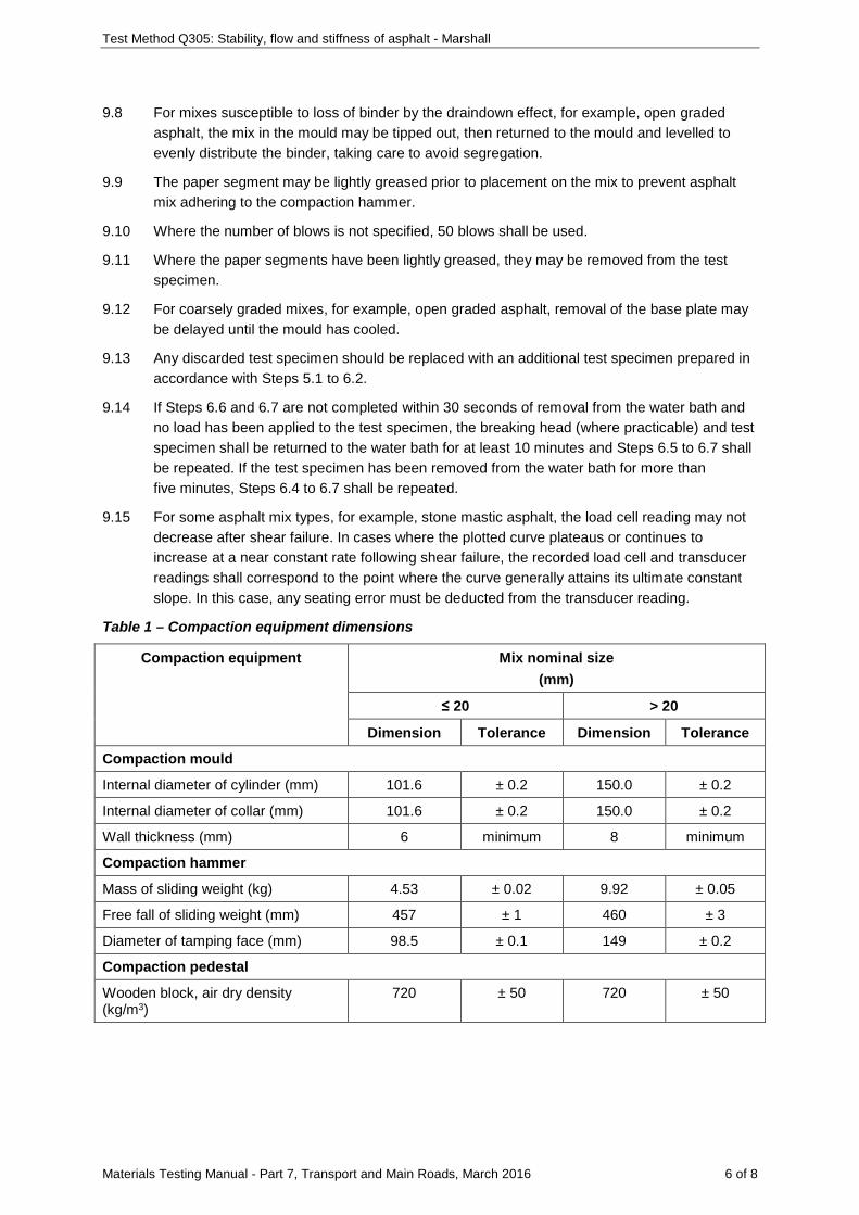
Table 1 – Compaction equipment dimensions
Compaction equipment Mix nominal size (mm)
≤ 20 > 20
Dimension Tolerance Dimension Tolerance
Compaction mould
Internal diameter of cylinder (mm) 101.6 ± 0.2 150.0 ± 0.2
Internal diameter of collar (mm) 101.6 ± 0.2 150.0 ± 0.2
Wall thickness (mm) 6 minimum 8 minimum
Compaction hammer
Mass of sliding weight (kg) 4.53 ± 0.02 9.92 ± 0.05
Free fall of sliding weight (mm) 457 ± 1 460 ± 3
Diameter of tamping face (mm) 98.5 ± 0.1 149 ± 0.2
Compaction pedestal
Wooden block, air dry density (kg/m3)
720 ± 50 720 ± 50
Test Method Q305: Stability, flow and stiffness of asphalt - Marshall
Materials Testing Manual - Part 7, Transport and Main Roads, March 2016 7 of 8
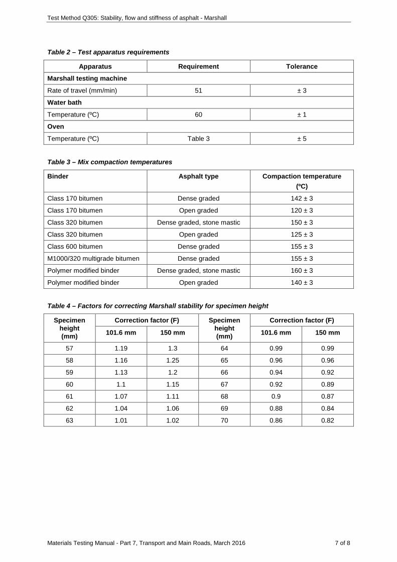
Table 2 – Test apparatus requirements
Apparatus Requirement Tolerance
Marshall testing machine
Rate of travel (mm/min) 51 ± 3
Water bath
Temperature (ºC) 60 ± 1
Oven
Temperature (ºC) Table 3 ± 5
Table 3 – Mix compaction temperatures
Binder Asphalt type Compaction temperature (ºC)
Class 170 bitumen Dense graded 142 ± 3
Class 170 bitumen Open graded 120 ± 3
Class 320 bitumen Dense graded, stone mastic 150 ± 3
Class 320 bitumen Open graded 125 ± 3
Class 600 bitumen Dense graded 155 ± 3
M1000/320 multigrade bitumen Dense graded 155 ± 3
Polymer modified binder Dense graded, stone mastic 160 ± 3
Polymer modified binder Open graded 140 ± 3
Table 4 – Factors for correcting Marshall stability for specimen height
Specimen height (mm)
Correction factor (F) Specimen height (mm)
Correction factor (F)
101.6 mm 150 mm 101.6 mm 150 mm
57 1.19 1.3 64 0.99 0.99
58 1.16 1.25 65 0.96 0.96
59 1.13 1.2 66 0.94 0.92
60 1.1 1.15 67 0.92 0.89
61 1.07 1.11 68 0.9 0.87
62 1.04 1.06 69 0.88 0.84
63 1.01 1.02 70 0.86 0.82
Test Method Q305: Stability, flow and stiffness of asphalt - Marshall
Materials Testing Manual - Part 7, Transport and Main Roads, March 2016 8 of 8
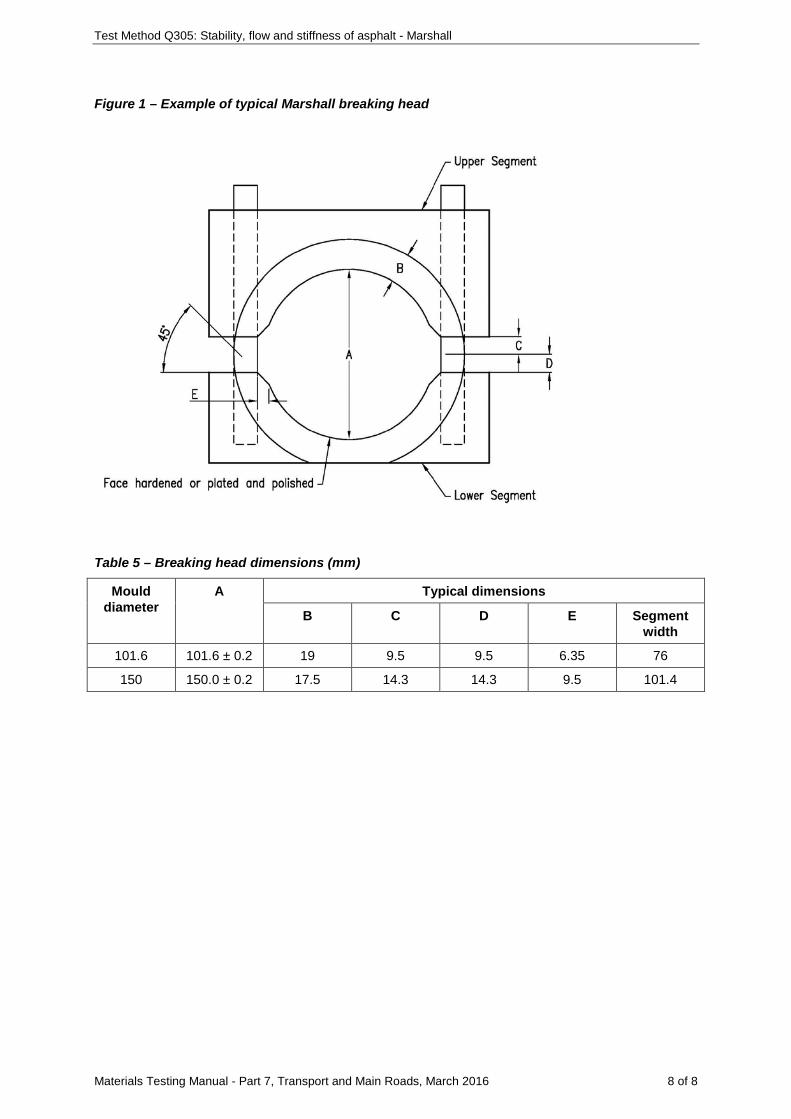
Figure 1 – Example of typical Marshall breaking head
Table 5 – Breaking head dimensions (mm)
Mould diameter
A Typical dimensions
B C D E Segment width
101.6 101.6 ± 0.2 19 9.5 9.5 6.35 76
150 150.0 ± 0.2 17.5 14.3 14.3 9.5 101.4
Materials Testing Manual - Part 7, Transport and Main Roads, March 2016 1 of 4
Test Method Q306A: Compacted density of dense graded asphalt - wax sealed
1 Source
This method is based on AS 2891.9.1: Determination of bulk density of compacted asphalt – waxing procedure.
2 Scope
This method describes a procedure for determining the compacted density of asphalt. It is applicable to dense graded asphalt either compacted in the laboratory or cut from the pavement.
3 Apparatus
The following apparatus is required:
3.1 Balance, a top pan balance of suitable capacity, with a resolution of at least 0.1 g and with a limit of performance within the range of ± 0.5 g. For testing in accordance with Subsection 5.2, the balance shall also be capable of below balance weighing.
3.2 Balance bench, equipped with a hole for below balance weighing.
3.3 Thermometer, a partial or total immersion thermometer or other suitable temperature measuring device having a temperature range which includes the test temperature, and graduated to 1ºC or less with an uncertainty of no more than 0.5ºC.
3.4 Attachment, a non-absorbent device to suspend the asphalt sample, for example, nylon or wire loop, wire support frame.
3.5 Paraffin wax bath, of sufficient capacity to completely contain the asphalt sample, and able to maintain the wax at a temperature of 10 ± 2ºC above its melting point.
3.6 Wire basket, able to support the asphalt sample on its side within the paraffin wax bath (Subsection 5.1.4 a) only).
3.7 Brush, a paint brush of about 13 mm width to apply the wax sealant to the sample.
3.8 Water container, fitted with an overflow and of suitable dimensions to allow the sample to be completely immersed without contacting any part of the container (Subsection 5.2 only).
3.9 Water container, of sufficient volume to contain the asphalt sample (Subsection 5.3 only).
3.10 Laboratory stand and clamp (Subsection 5.3 only).
4 Material
The following material is required:
4.1 Paraffin wax, of known density to the nearest 0.001 t/m3 (Note 8.1).
5 Procedure
The procedure shall be as follows:
5.1 Sample preparation
5.1.1 Where the sample is a core sample, prepare it in accordance with Test Method Q303A.
5.1.2 Air dry the sample to constant mass (Notes 8.2 and 8.3).
5.1.3 Determine the mass of the sample ( 1m ).
Test Method Q306A: Compacted density of dense graded asphalt - wax sealed
Materials Testing Manual - Part 7, Transport and Main Roads, March 2016 2 of 4
5.1.4 Coat the entire sample with wax using either of the following:
a) Wire basket method
i. Place the sample on its side in the wire basket and carefully lower the sample into the wax bath until it is complete immersed (Note 8.4).
ii. Immediately remove the wire basket and sample from the bath and allow the sample to cool (Note 8.5).
iii. Remove the sample from the wire basket and brush molten wax from the wax bath onto any unsealed areas of the sample.
iv. Allow the sample to cool to room temperature.
b) Hand dipping method
i. Dip the sample in the wax bath to half sample height (Note 8.6).
ii. Remove the sample from the wax bath and allow the wax to cool, ensuring no contact between the wax and any other surface (Note 8.5).
iii. Dip the sample in the wax bath to coat the unwaxed portion of the sample (Note 8.6).
iv. Remove the sample from the wax bath and allow the wax to cool to room temperature, ensuring no contact between the cooling wax and any other surface (Note 8.5).
v. Where required, brush molten wax from the wax bath onto any unsealed areas of the sample and allow the wax to cool to room temperature.
5.1.5 Determine the mass of the sealed sample ( 2m ).
5.2 Density measurement using below balance weighing
5.2.1 Place the container directly below the hole in the balance bench, fill it until water escapes from the overflow and allow the excess water to run to waste.
5.2.2 When water has ceased dripping from the overflow, fit the attachment to the balance, allow the remainder of the attachment to be immersed in the water container, and zero the balance.
5.2.3 Using the attachment, suspend the sealed sample from the balance and gently lower it into the water container until completely immersed, taking care to ensure that the suspended sample hangs free of the sides and bottom of the container.
5.2.4 Add additional water if necessary until water escapes from the overflow, and allow the excess water to run to waste.
5.2.5 When water has ceased dripping from the overflow, determine the mass of the immersed sealed sample ( 3m ).
5.2.6 Record the temperature of the water in the container to the nearest 1ºC.
5.3 Density measurement using above balance weighing
5.3.1 Add sufficient water to the container to completely immerse the sample. Place the container and water on the balance and zero the balance.
5.3.2 Position the laboratory stand and clamp so that the clamp is directly above the container on the balance.
Test Method Q306A: Compacted density of dense graded asphalt - wax sealed
Materials Testing Manual - Part 7, Transport and Main Roads, March 2016 3 of 4
5.3.3 Suspend the sealed sample from the clamp and gently lower it into the water container until completely immersed, taking care to ensure that the suspended sample hangs free of the sides and bottom of the container.
5.3.4 Determine the mass of the immersed sealed sample and attachment ( 3m ), noting the height
of water on the attachment at the time of weighing.
5.3.5 Remove the sample from the water container and zero the balance.
5.3.6 With the attachment immersed to the same depth as noted in Step 5.3.4, determine the mass of the suspended attachment ( 4m ).
5.3.7 Record the temperature of the water in the container to the nearest 1ºC.
6 Calculations
6.1 Below balance weighing
Calculate the compacted density of the sample as follows:
( ) ( )1
c2 3 2 1
w s
mD =m -m m -m
-D D
where cD = compacted density of sample (t/m3)
1m = mass of sample (g)
2m = mass of sealed sample (g)
3m = mass of immersed sealed sample (g)
wD = density of water at test temperature (t/m3) (Table 1)
sD = density of wax sealant (t/m3)
6.2 Above balance weighing
Calculate the compacted density of the sample as follows:
( ) ( )1
c3 4 2 1
w s
mD =m -m m -m
-D D
where cD = compacted density of sample (t/m3)
1m = mass of sample (g)
2m = mass of sealed sample (g)
3m = mass of immersed sealed sample and attachment (g)
4m = mass of immersed attachment (g)
wD = density of water at test temperature (t/m3) (Table 1)
Test Method Q306A: Compacted density of dense graded asphalt - wax sealed
Materials Testing Manual - Part 7, Transport and Main Roads, March 2016 4 of 4
sD = density of wax sealant (t/m3)
7 Reporting
Report the compacted density of the sample to the nearest 0.001 t/m3.
8 Notes on method
8.1 Before handling any wax, the operator must consult the relevant Safety Data Sheet (SDS).
8.2 A core sample may be assumed to be dry and not require drying to constant mass where:
• The core sample has been taken from the asphalt pavement using Test Method Q302A, and
• The asphalt pavement from which the core sample has been taken has remained dry since placement.
8.3 A sample is considered to have reached a constant mass when the difference between successive weighings, after a further 24 hours air drying, is not more than 0.03 percent.
8.4 During the waxing process, it is important that no air is trapped between the wax layer and the surface of the sample. It is equally important that wax does not penetrate the internal voids of the sample. The waxing process must then be conducted carefully and rapidly with good temperature control.
8.5 Should cracking of the wax occur during the coating process, the cracked wax must be removed and Step 5.1.4 repeated. Where necessary, the temperature of the wax in the bath may be increased to ensure a crack-free coating is obtained.
8.6 For core samples, the sample should be held with its curved surface down.
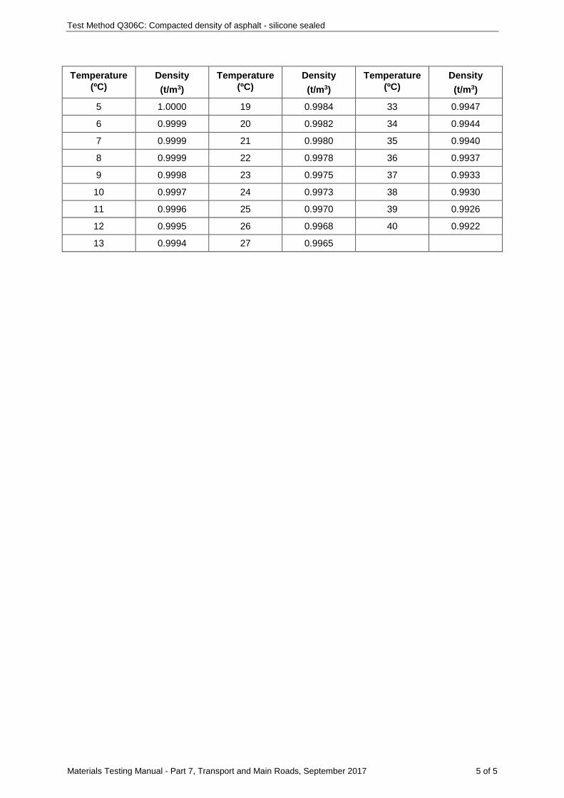
Table 1 – Density of water
Temperature (ºC)
Density (t/m3)
Temperature (ºC)
Density (t/m3)
Temperature (ºC)
Density (t/m3)
0 0.9998 14 0.9992 28 0.9962
1 0.9999 15 0.9991 29 0.9959
2 0.9999 16 0.9989 30 0.9957
3 1.0000 17 0.9988 31 0.9953
4 1.0000 18 0.9986 32 0.9950
5 1.0000 19 0.9984 33 0.9947
6 0.9999 20 0.9982 34 0.9944
7 0.9999 21 0.9980 35 0.9940
8 0.9999 22 0.9978 36 0.9937
9 0.9998 23 0.9975 37 0.9933
10 0.9997 24 0.9973 38 0.9930
11 0.9996 25 0.9970 39 0.9926
12 0.9995 26 0.9968 40 0.9922
13 0.9994 27 0.9965

Materials Testing Manual - Part 7, Transport and Main Roads, September 2017 1 of 1
Test Method Q306B: Compacted density of dense graded asphalt - presaturation
This test shall be performed in accordance with AS/NZS 2891.9.2: Determination of bulk density of compacted asphalt – Presaturation method, except that the following shall apply:
a) the requirements of Clause 6(a) shall not apply when testing prepared production mix.
Materials Testing Manual - Part 7, Transport and Main Roads, September 2017 1 of 5
Test Method Q306C: Compacted density of asphalt - silicone sealed
1 Source
This method was developed in-house using techniques evolved through internal departmental research investigations (Waters T.J., "Voids in Asphaltic Concrete", Report TT99, February 1986). It applies the principles of Test Method Q306A-2001: Compacted Density of Dense Graded Asphalt (Wax Sealed).
2 Scope
This method describes a procedure for determining the compacted density of asphalt. It is applicable to asphalt samples of all asphalt types either compacted in the laboratory or cut from the pavement. The method is non-destructive and removal of the sealant following testing allows the sample to be tested for other properties.
3 Apparatus
The following apparatus is required:
3.1 Balance, a top pan balance of suitable capacity, with a resolution of at least 0.1 g and with a limit of performance within the range of ± 0.5 g. For testing in accordance with Subsection 5.2, the balance shall also be capable of below balance weighing.
3.2 Balance bench, equipped with a hole for below balance weighing.
3.3 Thermometer, a partial or total immersion thermometer or other suitable temperature measuring device having a temperature range which includes the test temperature, and graduated to 1ºC or less with an uncertainty of no more than 0.5ºC.
3.4 Attachment, a non-absorbent device to suspend the asphalt sample, for example, nylon or wire loop, wire support frame.
3.5 Spatula, to apply the sealant to the sample.
3.6 Fan, an electric fan to disperse vapours emanating from the sealant during the curing period.
3.7 Water container, fitted with an overflow and of suitable dimensions to allow the sample to be completely immersed without contacting any part of the container (Subsection 5.2 only).
3.8 Water container, of sufficient volume to contain the asphalt sample (Subsection 5.3 only).
3.9 Laboratory stand and clamp (Subsection 5.3 only).
4 Material
The following material is required:
4.1 Sealant, an acetic cure silicone sealant of known density to the nearest 0.001 t/m3 (Note 8.1).
5 Procedure
The procedure shall be as follows:
5.1 Sample preparation
5.1.1 Where the sample is a core sample, prepare it in accordance with Test Method Q303A.
5.1.2 Air dry the sample to constant mass (Notes 8.2 and 8.3).
Test Method Q306C: Compacted density of asphalt - silicone sealed
Materials Testing Manual - Part 7, Transport and Main Roads, September 2017 2 of 5
5.1.3 Determine the mass of the sample ( 1m ).
5.1.4 Apply silicone sealant to approximately one half of the surface area of the sample to achieve a smooth and even finish (Note 8.4).
5.1.5 Place the sample in front of a fan and allow the sealant to cure to a firm and tack-free state.
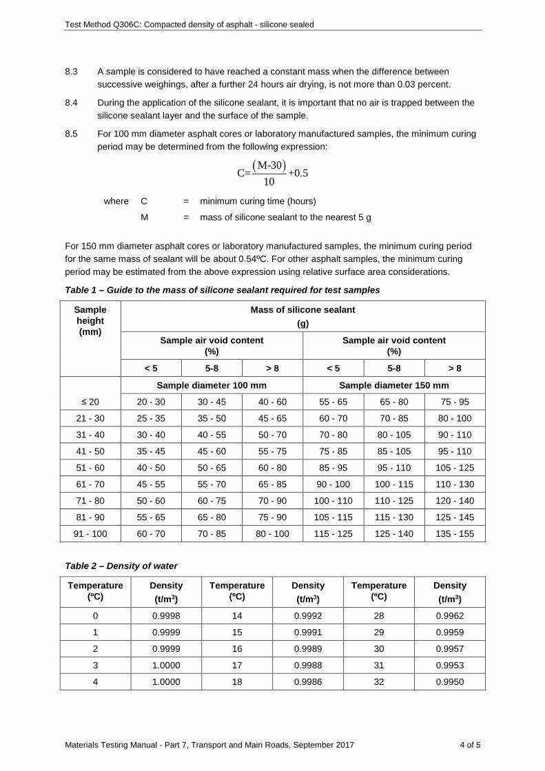
5.1.6 Apply silicone sealant to the remainder of the sample to achieve a smooth and even finish (Note 8.4). A guide to the mass of sealant required for different sample heights, diameters and air voids is given in Table 1.
5.1.7 Allow the sealant to cure (Note 8.5).
5.1.8 Inspect the sealed sample, apply silicone sealant to any unsealed areas and allow the sealant to cure.
5.1.9 Determine the mass of the sealed sample ( 2m ).
5.2 Density measurement using below balance weighing
5.2.1 Place the container directly below the hole in the balance bench, fill it until water escapes from the overflow and allow the excess water to run to waste.
5.2.2 When water has ceased dripping from the overflow, fit the attachment to the balance, allow the remainder of the attachment to be immersed in the water container, and zero the balance.
5.2.3 Using the attachment, suspend the sealed sample from the balance and gently lower it into the water container until completely immersed, taking care to ensure that the suspended sample hangs free of the sides and bottom of the container.
5.2.4 Add additional water if necessary until water escapes from the overflow, and allow the excess water to run to waste.
5.2.5 When water has ceased dripping from the overflow, determine the mass of the immersed sealed sample ( 3m ).
5.2.6 Record the temperature of the water in the container to the nearest 1ºC.
5.3 Density measurement using above balance weighing
5.3.1 Add sufficient water to the container to completely immerse the sample. Place the container and water on the balance and zero the balance.
5.3.2 Position the laboratory stand and clamp so that the clamp is directly above the container on the balance.
5.3.3 Suspend the sealed sample from the clamp and gently lower it into the water container until completely immersed, taking care to ensure that the suspended sample hangs free of the sides and bottom of the container.
5.3.4 Determine the mass of the immersed sealed sample and attachment ( 3m ), noting the height
of water on the attachment at the time of weighing.
5.3.5 Remove the sample from the water container and zero the balance.
5.3.6 With the attachment immersed to the same depth as noted in Step 5.3.4, determine the mass of the suspended attachment ( 4m ).
5.3.7 Record the temperature of the water in the container to the nearest 1ºC.
Test Method Q306C: Compacted density of asphalt - silicone sealed
Materials Testing Manual - Part 7, Transport and Main Roads, September 2017 3 of 5
6 Calculations
6.1 Below balance weighing
Calculate the compacted density of the sample as follows:
( ) ( )1
c2 3 2 1
w s
mD =m -m m -m
-D D
where cD = compacted density of sample (t/m3)
1m = mass of sample (g)
2m = mass of sealed sample (g)
3m = mass of immersed sealed sample (g)
wD = density of water at test temperature (t/m3) (Table 2)
sD = density of silicone sealant (t/m3)
6.2 Above balance weighing
Calculate the compacted density of the sample as follows:
( ) ( )1
c3 4 2 1
w s
mD =m -m m -m
-D D
where cD = compacted density of sample (t/m3)
1m = mass of sample (g)
2m = mass of sealed sample (g)
3m = mass of immersed sealed sample and attachment (g)
4m = mass of immersed attachment (g)
wD = density of water at test temperature (t/m3) (Table 2)
sD = density of silicone sealant (t/m3)
7 Reporting
Report the compacted density of the sample to the nearest 0.001 t/m3.
8 Notes on method
8.1 Before handling any sealant the operator must consult the relevant Safety Data Sheet (SDS).
8.2 A core sample may be assumed to be dry and not require drying to constant mass where:
• The core sample has been taken from the asphalt pavement using Test Method Q302A, and
• The asphalt pavement from which the core sample has been taken has remained dry since placement.
Test Method Q306C: Compacted density of asphalt - silicone sealed
Materials Testing Manual - Part 7, Transport and Main Roads, September 2017 4 of 5
8.3 A sample is considered to have reached a constant mass when the difference between successive weighings, after a further 24 hours air drying, is not more than 0.03 percent.
8.4 During the application of the silicone sealant, it is important that no air is trapped between the silicone sealant layer and the surface of the sample.
8.5 For 100 mm diameter asphalt cores or laboratory manufactured samples, the minimum curing period may be determined from the following expression:
( )M-30C= +0.5
10
where C = minimum curing time (hours)
M = mass of silicone sealant to the nearest 5 g
For 150 mm diameter asphalt cores or laboratory manufactured samples, the minimum curing period for the same mass of sealant will be about 0.54ºC. For other asphalt samples, the minimum curing period may be estimated from the above expression using relative surface area considerations.
Table 1 – Guide to the mass of silicone sealant required for test samples
Sample height (mm)
Mass of silicone sealant (g)
Sample air void content (%)
Sample air void content (%)
< 5 5-8 > 8 < 5 5-8 > 8
≤ 20
Sample diameter 100 mm Sample diameter 150 mm
20 - 30 30 - 45 40 - 60 55 - 65 65 - 80 75 - 95
21 - 30 25 - 35 35 - 50 45 - 65 60 - 70 70 - 85 80 - 100
31 - 40 30 - 40 40 - 55 50 - 70 70 - 80 80 - 105 90 - 110
41 - 50 35 - 45 45 - 60 55 - 75 75 - 85 85 - 105 95 - 110
51 - 60 40 - 50 50 - 65 60 - 80 85 - 95 95 - 110 105 - 125
61 - 70 45 - 55 55 - 70 65 - 85 90 - 100 100 - 115 110 - 130
71 - 80 50 - 60 60 - 75 70 - 90 100 - 110 110 - 125 120 - 140
81 - 90 55 - 65 65 - 80 75 - 90 105 - 115 115 - 130 125 - 145
91 - 100 60 - 70 70 - 85 80 - 100 115 - 125 125 - 140 135 - 155
Table 2 – Density of water
Temperature (ºC)
Density (t/m3)
Temperature (ºC)
Density (t/m3)
Temperature (ºC)
Density (t/m3)
0 0.9998 14 0.9992 28 0.9962
1 0.9999 15 0.9991 29 0.9959
2 0.9999 16 0.9989 30 0.9957
3 1.0000 17 0.9988 31 0.9953
4 1.0000 18 0.9986 32 0.9950
Test Method Q306C: Compacted density of asphalt - silicone sealed
Materials Testing Manual - Part 7, Transport and Main Roads, September 2017 5 of 5
Temperature (ºC)
Density (t/m3)
Temperature (ºC)
Density (t/m3)
Temperature (ºC)
Density (t/m3)
5 1.0000 19 0.9984 33 0.9947
6 0.9999 20 0.9982 34 0.9944
7 0.9999 21 0.9980 35 0.9940
8 0.9999 22 0.9978 36 0.9937
9 0.9998 23 0.9975 37 0.9933
10 0.9997 24 0.9973 38 0.9930
11 0.9996 25 0.9970 39 0.9926
12 0.9995 26 0.9968 40 0.9922
13 0.9994 27 0.9965

Materials Testing Manual - Part 7, Transport and Main Roads, September 2017 1 of 1
Test Method Q306D: Compacted density of asphalt - mensuration
This test shall be performed in accordance with AS/NZS 2891.9.3: Determination of bulk density of compacted asphalt – Mensuration method.

Materials Testing Manual - Part 7, Transport and Main Roads, November 2014 1 of 1
Test Method Q306E: Compacted density of asphalt - nuclear gauge
This test shall be performed in accordance with Test Method N04: Compacted Density of Asphalt contained within the department's Nuclear Gauge Testing Manual.

Materials Testing Manual - Part 7, Transport and Main Roads, September 2017 1 of 1
Test Method Q307A: Maximum density of asphalt – water displacement
This test shall be performed in accordance with AS 2891.7.1: Determination of maximum density of asphalt – Water displacement method except as follows:
• Add the following to clause 6 (a) "For nominal size mix 20 mm or greater, a pycnometer of about 3 L capacity may be used."
Materials Testing Manual - Part 7, Transport and Main Roads, September 2017 1 of 6
Test Method Q308A: Binder content and aggregate grading of asphalt – reflux method
1 Source
This method applies the principles of AS/NZS 2891.3.1: Binder content and aggregate grading - Reflux method.
2 Scope
This method describes the procedure for the determination of the binder content of asphalt by solvent extraction and, subsequently, the particle size distribution of the aggregate by sieve analysis.
3 Apparatus
Where appropriate, the working tolerances of particular apparatus are contained in Table 1.
The following apparatus is required:
3.1 Balances:
3.1.1 Balance of suitable capacity, with a resolution of at least 0.1 g and with a limit of performance within the range of ± 0.5 g.
3.1.2 Balance of suitable capacity, with a resolution of at least 0.001 g and with a limit of performance within the range of ± 0.005 g.
3.2 Oven of suitable capacity, thermostatically controlled to operate at a temperature of at least 105°C.
3.3 Centrifuge, an electric centrifuge capable of holding at least two 15 mL aliquots.
3.4 Hotplate, capable of maintaining a temperature of 305ºC (Note 10.1).
3.5 Fume cupboard.
3.6 Flask, conical flask of 2 L capacity with a ground glass neck of at least 55 mm diameter and fitted with a stopper.
3.7 Condenser, double surface condenser to fit the neck of the flask.
3.8 Beaker, of at least 100 mL capacity.
3.9 Containers, two flat-bottomed aluminium containers of approximate dimensions 100 mm diameter and 75 mm depth and equipped with tightly fitting slip-on lids.
3.10 Metal tray, of sufficient capacity to contain the aggregate.
3.11 Sieves, 37.5 mm, 26.5 mm, 19.0 mm, 13.2 mm, 9.50 mm, 6.70 mm, 4.75 mm, 2.36 mm, 1.18 mm, 0.600 mm, 0.300 mm, 0.150 mm, 0.075 mm and reinforced 0.075 mm as required complying with AS 1152.
3.12 Sieve brush.
3.13 Mechanical sieve shaker (optional).
4 Materials
The following materials are required:
4.1 Solvent, toluene commercial grade (Notes 10.2 and 10.3).
Test Method Q308A: Binder content and aggregate grading of asphalt – reflux method
Materials Testing Manual – Part 7, Transport and Main Roads, September 2017 2 of 6
4.2 Washing solvent such as kerosene, mineral turpentine or similar (optional) (Note 10.2).
5 Procedure – binder content
The following procedure shall be conducted on a single test portion for asphalt of nominal size less than 20 mm and on two test portions for asphalt of nominal size 20 mm or larger (Note 10.4).
5.1 Weigh the flask with stopper and record the mass to the nearest 0.1 g ( 1m ).
5.2 If necessary, warm the test sample just sufficiently by heating, preferably in the oven, to loosen the mass of material.
5.3 Obtain a representative sample of approximately 1200 g by coning and quartering in accordance with Subsection 4.2 of Test Method Q301.
5.4 With the flask held at an angle of about 45 degrees, transfer the sample to the flask and allow it to cool. Weigh the flask with stopper and record the mass to the nearest 0.1 g ( 2m ).
5.5 Add a quantity of solvent to the flask at least equivalent in mass to the sample mass.
5.6 Fit the reflux condenser to the flask and gently warm the flask and contents on the hotplate in the fume cupboard to dissolve the binder (Note 10.5). Shake the flask frequently during this refluxing operation to prevent binder from caking on the bottom of the flask.
5.7 Allow the flask to cool to room temperature with the condenser still in position. Remove the condenser and fit the stopper.
5.8 Weigh the flask and stopper and record the mass to the nearest 0.1 g ( 3m ).
5.9 Perform the following procedure on two aliquots:
5.9.1 Using the beaker, transfer an aliquot of at least 15 mL of the solution from the flask to the centrifuge tube(s). Stopper the tube(s) immediately and centrifuge to separate any suspended mineral matter.
5.9.2 Weigh a container with lid and record the mass to the nearest 0.001 g ( 4m ).
5.9.3 Pour the supernatant liquid from the centrifuge tube(s) into the container, taking care not to disturb the settled mineral matter, and fit the lid. Weigh the container immediately and record the mass to the nearest 0.001 g ( 5m ).
5.9.4 Remove the lid and place the container on the hotplate maintained at a temperature of 305 10ºC in the fume cupboard to evaporate the solvent. Continue the heating for two minutes after fumes are first seen to rise from the binder (Notes 10.1 and 10.6).
5.9.5 Remove the container from the hotplate, replace the lid and allow the container to cool to room temperature.
5.9.6 Weigh the container and lid and record the mass to the nearest 0.001 g ( 6m ).
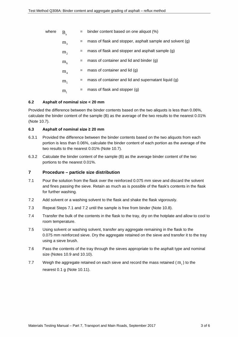
6 Calculations – binder content
6.1 Calculate the binder content based on each aliquot to the nearest 0.01% as follows:
( )( )( )( )
3 2 6 4a
5 6 2 1
m m m m 100B
m m m m− −
=− −
Test Method Q308A: Binder content and aggregate grading of asphalt – reflux method
Materials Testing Manual – Part 7, Transport and Main Roads, September 2017 3 of 6
where aB = binder content based on one aliquot (%)
3m = mass of flask and stopper, asphalt sample and solvent (g)
2m = mass of flask and stopper and asphalt sample (g)
6m = mass of container and lid and binder (g)
4m = mass of container and lid (g)
5m = mass of container and lid and supernatant liquid (g)
1m = mass of flask and stopper (g)
6.2 Asphalt of nominal size < 20 mm
Provided the difference between the binder contents based on the two aliquots is less than 0.06%, calculate the binder content of the sample (B) as the average of the two results to the nearest 0.01% (Note 10.7).
6.3 Asphalt of nominal size ≥ 20 mm
6.3.1 Provided the difference between the binder contents based on the two aliquots from each portion is less than 0.06%, calculate the binder content of each portion as the average of the two results to the nearest 0.01% (Note 10.7).
6.3.2 Calculate the binder content of the sample (B) as the average binder content of the two portions to the nearest 0.01%.
7 Procedure – particle size distribution
7.1 Pour the solution from the flask over the reinforced 0.075 mm sieve and discard the solvent and fines passing the sieve. Retain as much as is possible of the flask's contents in the flask for further washing.
7.2 Add solvent or a washing solvent to the flask and shake the flask vigorously.
7.3 Repeat Steps 7.1 and 7.2 until the sample is free from binder (Note 10.8).
7.4 Transfer the bulk of the contents in the flask to the tray, dry on the hotplate and allow to cool to room temperature.
7.5 Using solvent or washing solvent, transfer any aggregate remaining in the flask to the 0.075 mm reinforced sieve. Dry the aggregate retained on the sieve and transfer it to the tray using a sieve brush.
7.6 Pass the contents of the tray through the sieves appropriate to the asphalt type and nominal size (Notes 10.9 and 10.10).
7.7 Weigh the aggregate retained on each sieve and record the mass retained ( rm ) to the
nearest 0.1 g (Note 10.11).
Test Method Q308A: Binder content and aggregate grading of asphalt – reflux method
Materials Testing Manual – Part 7, Transport and Main Roads, September 2017 4 of 6
8 Calculations – particle size distribution
8.1 Asphalt of nominal size < 20 mm
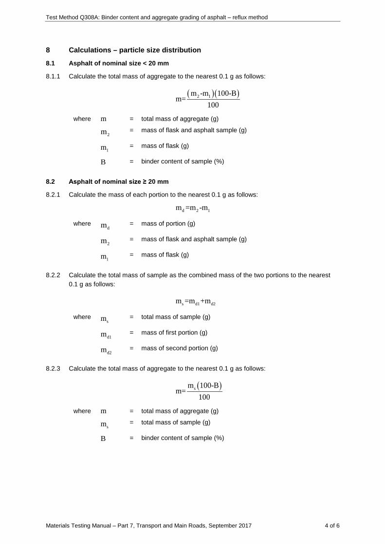
8.1.1 Calculate the total mass of aggregate to the nearest 0.1 g as follows:
( )( )2 1m -m 100-Bm=
100 where m = total mass of aggregate (g)
2m = mass of flask and asphalt sample (g)
1m = mass of flask (g)
B = binder content of sample (%)
8.2 Asphalt of nominal size ≥ 20 mm
8.2.1 Calculate the mass of each portion to the nearest 0.1 g as follows:
d 2 1m =m -m
where dm = mass of portion (g)
2m = mass of flask and asphalt sample (g)
1m = mass of flask (g)
8.2.2 Calculate the total mass of sample as the combined mass of the two portions to the nearest 0.1 g as follows:
s d1 d2m =m +m where
sm = total mass of sample (g)
d1m = mass of first portion (g)
d2m = mass of second portion (g)
8.2.3 Calculate the total mass of aggregate to the nearest 0.1 g as follows:
( )sm 100-Bm=
100 where m = total mass of aggregate (g)
sm = total mass of sample (g)
B = binder content of sample (%)
Test Method Q308A: Binder content and aggregate grading of asphalt – reflux method
Materials Testing Manual – Part 7, Transport and Main Roads, September 2017 5 of 6
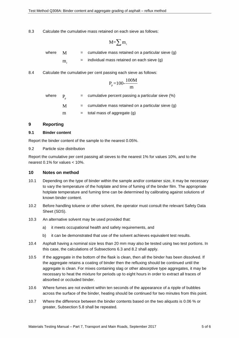
8.3 Calculate the cumulative mass retained on each sieve as follows:
rM= m∑ where M = cumulative mass retained on a particular sieve (g)
rm = individual mass retained on each sieve (g)
8.4 Calculate the cumulative per cent passing each sieve as follows:
p100MP =100-
m
where pP = cumulative percent passing a particular sieve (%)
M = cumulative mass retained on a particular sieve (g)
m = total mass of aggregate (g)
9 Reporting
9.1 Binder content
Report the binder content of the sample to the nearest 0.05%.
9.2 Particle size distribution
Report the cumulative per cent passing all sieves to the nearest 1% for values 10%, and to the nearest 0.1% for values < 10%.
10 Notes on method
10.1 Depending on the type of binder within the sample and/or container size, it may be necessary to vary the temperature of the hotplate and time of fuming of the binder film. The appropriate hotplate temperature and fuming time can be determined by calibrating against solutions of known binder content.
10.2 Before handling toluene or other solvent, the operator must consult the relevant Safety Data Sheet (SDS).
10.3 An alternative solvent may be used provided that:
a) it meets occupational health and safety requirements, and
b) it can be demonstrated that use of the solvent achieves equivalent test results.
10.4 Asphalt having a nominal size less than 20 mm may also be tested using two test portions. In this case, the calculations of Subsections 6.3 and 8.2 shall apply.
10.5 If the aggregate in the bottom of the flask is clean, then all the binder has been dissolved. If the aggregate retains a coating of binder then the refluxing should be continued until the aggregate is clean. For mixes containing slag or other absorptive type aggregates, it may be necessary to heat the mixture for periods up to eight hours in order to extract all traces of absorbed or occluded binder.
10.6 Where fumes are not evident within ten seconds of the appearance of a ripple of bubbles across the surface of the binder, heating should be continued for two minutes from this point.
10.7 Where the difference between the binder contents based on the two aliquots is 0.06 % or greater, Subsection 5.8 shall be repeated.
Test Method Q308A: Binder content and aggregate grading of asphalt – reflux method
Materials Testing Manual – Part 7, Transport and Main Roads, September 2017 6 of 6
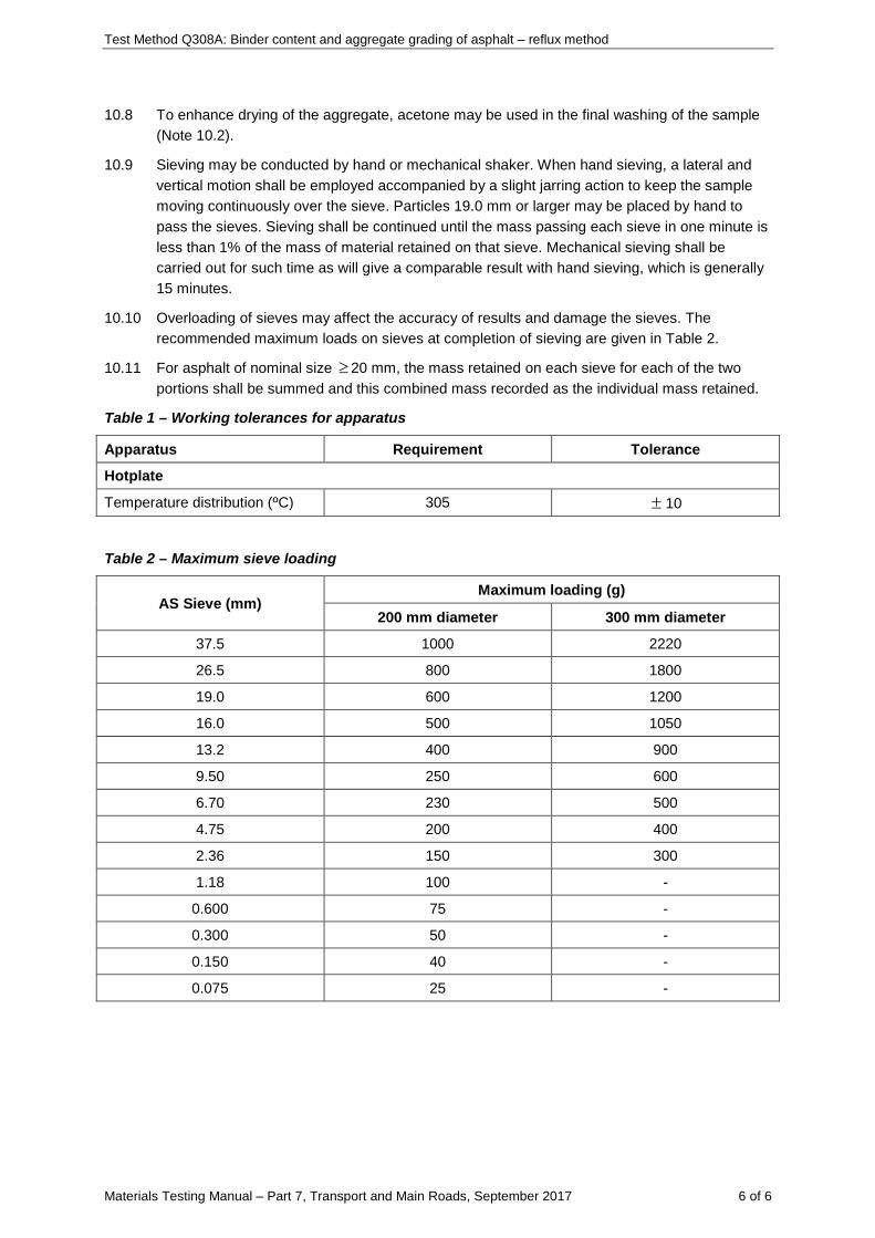
10.8 To enhance drying of the aggregate, acetone may be used in the final washing of the sample (Note 10.2).
10.9 Sieving may be conducted by hand or mechanical shaker. When hand sieving, a lateral and vertical motion shall be employed accompanied by a slight jarring action to keep the sample moving continuously over the sieve. Particles 19.0 mm or larger may be placed by hand to pass the sieves. Sieving shall be continued until the mass passing each sieve in one minute is less than 1% of the mass of material retained on that sieve. Mechanical sieving shall be carried out for such time as will give a comparable result with hand sieving, which is generally 15 minutes.
10.10 Overloading of sieves may affect the accuracy of results and damage the sieves. The recommended maximum loads on sieves at completion of sieving are given in Table 2.
10.11 For asphalt of nominal size ≥ 20 mm, the mass retained on each sieve for each of the two portions shall be summed and this combined mass recorded as the individual mass retained.
Table 1 – Working tolerances for apparatus
Apparatus Requirement Tolerance
Hotplate
Temperature distribution (ºC) 305 ± 10
Table 2 – Maximum sieve loading
AS Sieve (mm) Maximum loading (g)
200 mm diameter 300 mm diameter
37.5 1000 2220
26.5 800 1800
19.0 600 1200
16.0 500 1050
13.2 400 900
9.50 250 600
6.70 230 500
4.75 200 400
2.36 150 300
1.18 100 -
0.600 75 -
0.300 50 -
0.150 40 -
0.075 25 -
Materials Testing Manual - Part 7, Transport and Main Roads, November 2014 1 of 7
Test Method Q308C: Binder content and aggregate grading of emulsion based cold mix
1 Source
This method applies the principles of AS 2891.3.1: Bitumen content and aggregate grading - Reflux method and the procedure for water content determination described in AS 2891.10: Water and volatile oils content.
2 Scope
This method describes the procedure for the determination of the binder content and aggregate grading of cold mix which has been prepared using bituminous emulsion and has negligible volatile oils content, for example, bituminous slurry surfacing. The method involves extraction of residual water in the mix and determination of the binder content by solvent extraction and the particle size distribution of the aggregate by sieve analysis.
3 Apparatus
Where appropriate, the working tolerances of particular apparatus are contained in Table 1.
The following apparatus is required:
3.1 Balances:
3.1.1 Balance of suitable capacity, with a resolution of at least 0.1 g and with a limit of performance within the range of ± 0.5 g.
3.1.2 Balance of suitable capacity, with a resolution of at least 0.001 g and with a limit of performance within the range of ± 0.005 g.
3.2 Centrifuge, an electric centrifuge capable of holding at least two 15 mL aliquots.
3.3 Hotplate, capable of maintaining a temperature of 305ºC (Note 10.1).
3.4 Fume cupboard.
3.5 Heating mantle, electric heating mantle of suitable size to heat the 1 L flask and contents.
3.6 Receiver, a standard Dean and Stark light entrainer of 25 mL capacity.
3.7 Adaptors, as required to connect the flask, receiver and condenser.
3.8 Pipette, 10 mL pipette graduated in 0.1 mL increments.
3.9 Flask, round bottom flask of 1 L capacity with a ground glass neck of at least 55 mm diameter and fitted with a stopper.
3.10 Condenser, double surface condenser to fit the neck of the flask.
3.11 Beaker, of at least 100 mL capacity.
3.12 Containers, two flat-bottomed aluminium containers of approximate dimensions 100 mm diameter and 75 mm depth and equipped with tightly fitting slip-on lids.
3.13 Metal tray, of sufficient capacity to contain the aggregate.
3.14 Sieves, 37.5 mm, 26.5 mm, 19.0 mm, 13.2 mm, 9.50 mm, 6.70 mm, 4.75 mm, 2.36 mm, 1.18 mm, 0.600 mm, 0.300 mm, 0.150 mm, 0.075 mm and reinforced 0.075 mm as required complying with AS 1152.
3.15 Sieve brush.
Test Method Q308C: Binder content and aggregate grading of emulsion based cold mix
Materials Testing Manual - Part 7, Transport and Main Roads, November 2014 2 of 7
3.16 Mechanical sieve shaker (optional).
4 Materials
The following materials are required:
4.1 Solvent, toluene commercial grade (Note 10.2).
4.2 Washing solvent such as kerosene, mineral turpentine or similar (optional) (Note 10.2).
5 Procedure – binder content
The following procedure shall be conducted on a single test portion for asphalt of nominal size less than 20 mm and on two test portions for asphalt of nominal size 20 mm or larger.
5.1 Determine the mass of the flask with stopper ( 1m ).
5.2 Obtain a representative sample of approximately 500 g by coning and quartering in accordance with Subsection 4.2 of Test Method Q301.
5.3 With the flask held at an angle of about 45 degrees, transfer the sample to the flask. Determine the mass of the flask, stopper and sample ( 2m ).
5.4 Add sufficient solvent to the flask so that the level of solvent is at least 25 mm above the level of the sample.
5.5 Place the flask in the heating mantle, fit the receiver and condenser to the flask and turn on the water supply to the condenser.
5.6 Apply heat to the flask, cautiously at first, and then regulated so that the condensate falls at a rate of 2 to 5 drops per second.
5.7 Continue heating until the volume of water in the receiver remains constant for 15 minutes (Note 10.3).
5.8 Discontinue heating and allow the water in the receiver to cool to room temperature.
5.9 Dislodge any droplets of water adhering to the inner surface of the receiver using a length of straight wire. Record the volume of water in the receiver to the nearest 0.1 mL ( v ) and measure the room temperature to the nearest 1ºC.
5.10 Remove the flask from the receiver, stopper the flask and allow the contents to cool to room temperature.
5.11 Examine the contents of the flask to ensure that all binder has been dissolved (Note 10.4), then determine the mass of the flask, mix and solvent ( 3m ).
5.12 Perform the following procedure on two aliquots:
5.12.1 Using the beaker, transfer an aliquot of at least 15 mL of the solution from the flask to the centrifuge tube(s). Stopper the tube(s) immediately and centrifuge to separate any suspended mineral matter.
5.12.2 Determine the mass of the container with lid to the nearest 0.001 g ( 4m ).
5.12.3 Pour the supernatant liquid from the centrifuge tube(s) into the container, taking care not to disturb the settled mineral matter, and fit the lid. Determine the mass of the container and supernatant liquid immediately to the nearest 0.001 g ( 5m ).
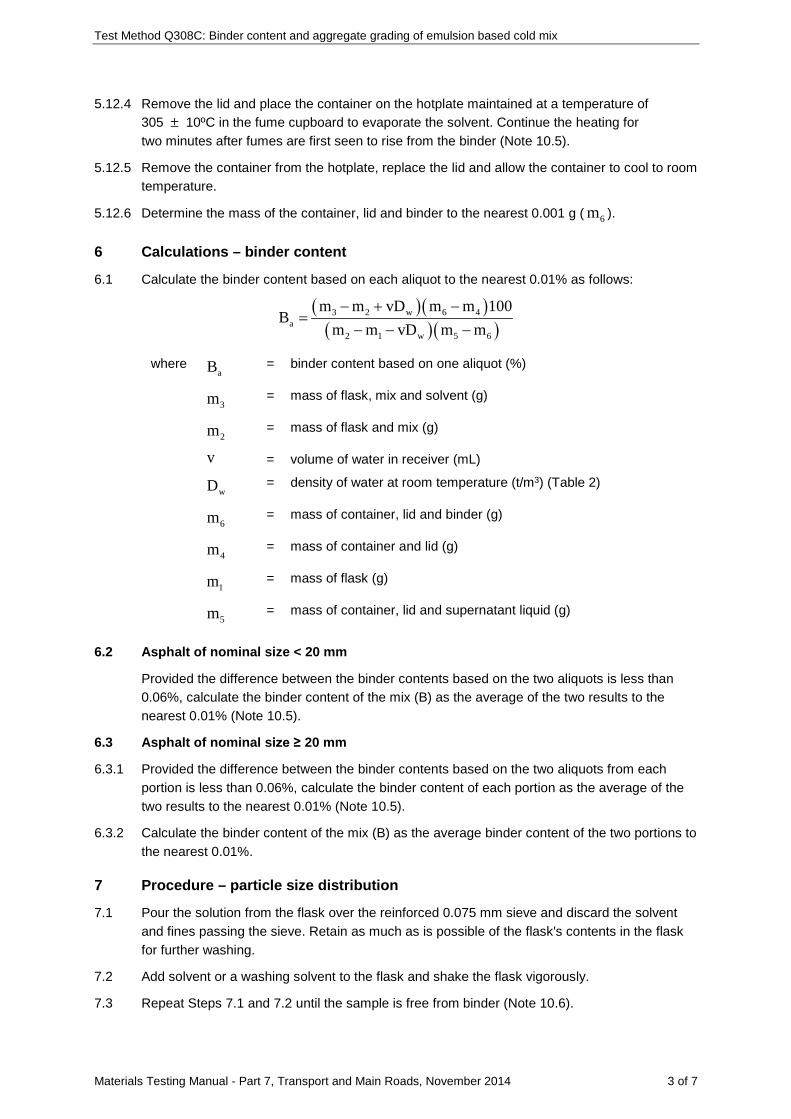
Test Method Q308C: Binder content and aggregate grading of emulsion based cold mix
Materials Testing Manual - Part 7, Transport and Main Roads, November 2014 3 of 7
5.12.4 Remove the lid and place the container on the hotplate maintained at a temperature of 305 ± 10ºC in the fume cupboard to evaporate the solvent. Continue the heating for two minutes after fumes are first seen to rise from the binder (Note 10.5).
5.12.5 Remove the container from the hotplate, replace the lid and allow the container to cool to room temperature.
5.12.6 Determine the mass of the container, lid and binder to the nearest 0.001 g ( 6m ).
6 Calculations – binder content
6.1 Calculate the binder content based on each aliquot to the nearest 0.01% as follows:
( )( )( )( )
3 2 w 6 4a
2 1 w 5 6
m m vD m m 100B
m m vD m m− + −
=− − −
where aB = binder content based on one aliquot (%)
3m = mass of flask, mix and solvent (g)
2m = mass of flask and mix (g)
v = volume of water in receiver (mL)
wD = density of water at room temperature (t/m3) (Table 2)
6m = mass of container, lid and binder (g)
4m = mass of container and lid (g)
1m = mass of flask (g)
5m = mass of container, lid and supernatant liquid (g)
6.2 Asphalt of nominal size < 20 mm
Provided the difference between the binder contents based on the two aliquots is less than 0.06%, calculate the binder content of the mix (B) as the average of the two results to the nearest 0.01% (Note 10.5).
6.3 Asphalt of nominal size ≥ 20 mm
6.3.1 Provided the difference between the binder contents based on the two aliquots from each portion is less than 0.06%, calculate the binder content of each portion as the average of the two results to the nearest 0.01% (Note 10.5).
6.3.2 Calculate the binder content of the mix (B) as the average binder content of the two portions to the nearest 0.01%.
7 Procedure – particle size distribution
7.1 Pour the solution from the flask over the reinforced 0.075 mm sieve and discard the solvent and fines passing the sieve. Retain as much as is possible of the flask's contents in the flask for further washing.
7.2 Add solvent or a washing solvent to the flask and shake the flask vigorously.
7.3 Repeat Steps 7.1 and 7.2 until the sample is free from binder (Note 10.6).
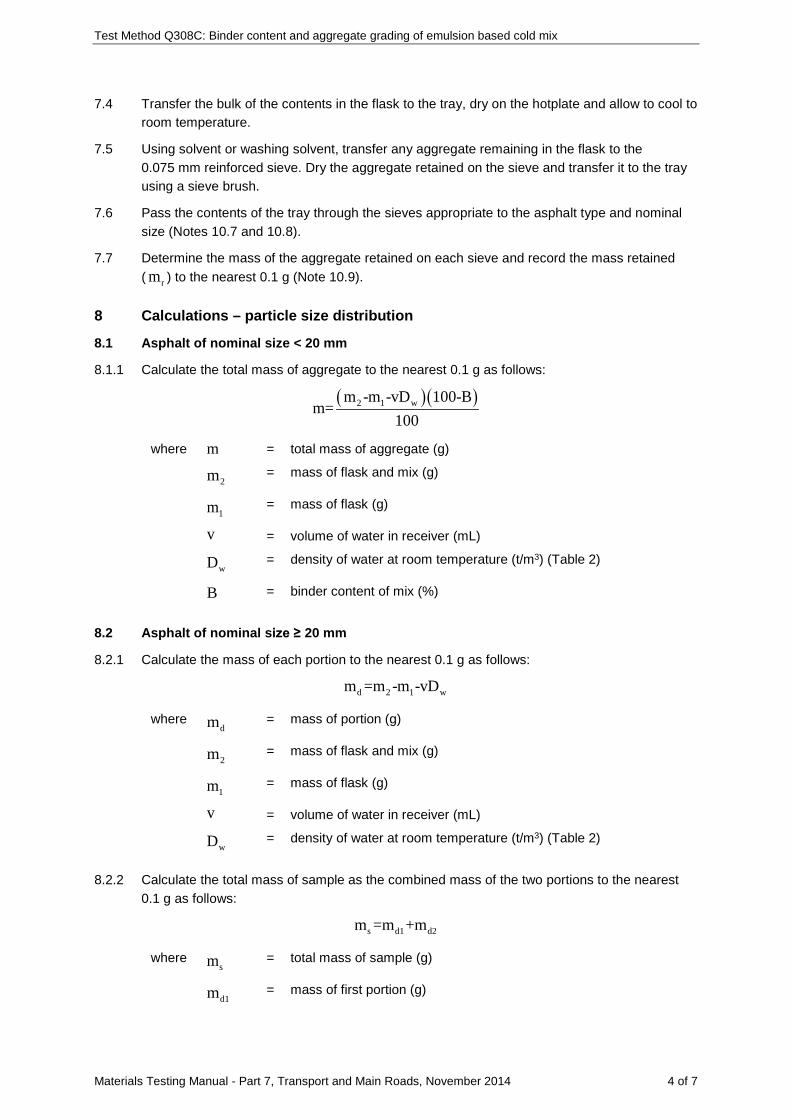
Test Method Q308C: Binder content and aggregate grading of emulsion based cold mix
Materials Testing Manual - Part 7, Transport and Main Roads, November 2014 4 of 7
7.4 Transfer the bulk of the contents in the flask to the tray, dry on the hotplate and allow to cool to room temperature.
7.5 Using solvent or washing solvent, transfer any aggregate remaining in the flask to the 0.075 mm reinforced sieve. Dry the aggregate retained on the sieve and transfer it to the tray using a sieve brush.
7.6 Pass the contents of the tray through the sieves appropriate to the asphalt type and nominal size (Notes 10.7 and 10.8).
7.7 Determine the mass of the aggregate retained on each sieve and record the mass retained ( rm ) to the nearest 0.1 g (Note 10.9).
8 Calculations – particle size distribution
8.1 Asphalt of nominal size < 20 mm
8.1.1 Calculate the total mass of aggregate to the nearest 0.1 g as follows:
( )( )2 1 wm -m -vD 100-Bm=
100
where m = total mass of aggregate (g)
2m = mass of flask and mix (g)
1m = mass of flask (g)
v = volume of water in receiver (mL)
wD = density of water at room temperature (t/m3) (Table 2)
B = binder content of mix (%)
8.2 Asphalt of nominal size ≥ 20 mm
8.2.1 Calculate the mass of each portion to the nearest 0.1 g as follows:
d 2 1 wm =m -m -vD
where dm = mass of portion (g)
2m = mass of flask and mix (g)
1m = mass of flask (g)
v = volume of water in receiver (mL)
wD = density of water at room temperature (t/m3) (Table 2)
8.2.2 Calculate the total mass of sample as the combined mass of the two portions to the nearest 0.1 g as follows:
s d1 d2m =m +m
where sm = total mass of sample (g)
d1m = mass of first portion (g)
Test Method Q308C: Binder content and aggregate grading of emulsion based cold mix
Materials Testing Manual - Part 7, Transport and Main Roads, November 2014 5 of 7
d2m = mass of second portion (g)
8.2.3 Calculate the total mass of aggregate to the nearest 0.1 g as follows:
( )sm 100-Bm=
100
where m = total mass of aggregate (g)
sm = total mass of sample (g)
B = binder content of mix (%)
8.3 Calculate the cumulative mass retained on each sieve as follows:
rM= m∑
where M = cumulative mass retained on a particular sieve (g)
rm = individual mass retained on each sieve (g)
8.4 Calculate the cumulative per cent passing each sieve as follows:
p100MP =100-
m
where pP = cumulative percent passing a particular sieve (%)
M = cumulative mass retained on a particular sieve (g)
m = total mass of aggregate (g)
9 Reporting
9.1 Binder content
Report the binder content of the sample to the nearest 0.05%.
9.2 Particle size distribution
Report the cumulative per cent passing all sieves to the nearest 1% for values ≥10%, and to the nearest 0.1% for values <10%.
10 Notes on method
10.1 Depending on the type of binder within the sample and/or container size, it may be necessary to vary the temperature of the hotplate and time of fuming of the binder film. The appropriate hotplate temperature and fuming time can be determined by calibrating against solutions of known binder content.
10.2 Before handling toluene or other solvent, the operator must consult the relevant Safety Data Sheet (SDS).
10.3 Where the volume of water extracted from the sample exceeds the capacity of the receiver, a portion of the water may be drawn off using the pipette and the volume recorded to the nearest 0.1 mL. This value shall be added to that recorded in Step 5.9 to obtain the volume v.
10.4 If the aggregate in the bottom of the flask is clean, then all the binder has been dissolved. If the aggregate retains a coating of binder then the refluxing should be continued until the
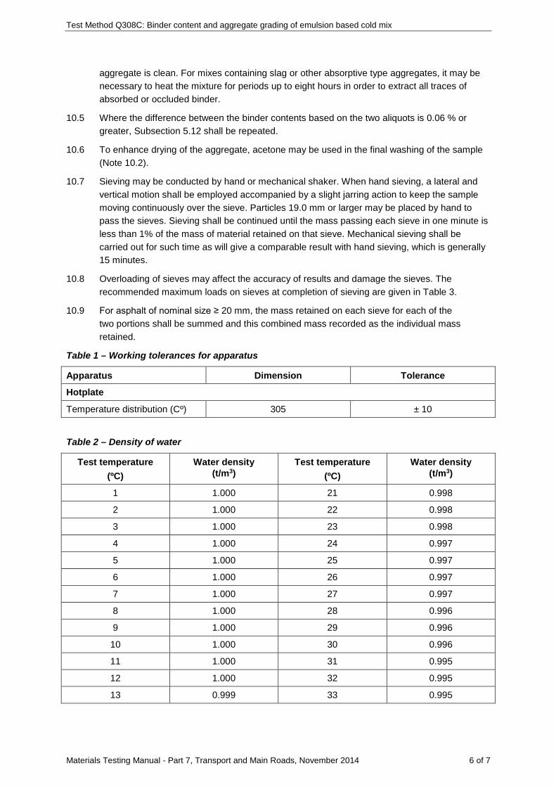
Test Method Q308C: Binder content and aggregate grading of emulsion based cold mix
Materials Testing Manual - Part 7, Transport and Main Roads, November 2014 6 of 7
aggregate is clean. For mixes containing slag or other absorptive type aggregates, it may be necessary to heat the mixture for periods up to eight hours in order to extract all traces of absorbed or occluded binder.
10.5 Where the difference between the binder contents based on the two aliquots is 0.06 % or greater, Subsection 5.12 shall be repeated.
10.6 To enhance drying of the aggregate, acetone may be used in the final washing of the sample (Note 10.2).
10.7 Sieving may be conducted by hand or mechanical shaker. When hand sieving, a lateral and vertical motion shall be employed accompanied by a slight jarring action to keep the sample moving continuously over the sieve. Particles 19.0 mm or larger may be placed by hand to pass the sieves. Sieving shall be continued until the mass passing each sieve in one minute is less than 1% of the mass of material retained on that sieve. Mechanical sieving shall be carried out for such time as will give a comparable result with hand sieving, which is generally 15 minutes.
10.8 Overloading of sieves may affect the accuracy of results and damage the sieves. The recommended maximum loads on sieves at completion of sieving are given in Table 3.
10.9 For asphalt of nominal size ≥ 20 mm, the mass retained on each sieve for each of the two portions shall be summed and this combined mass recorded as the individual mass retained.
Table 1 – Working tolerances for apparatus
Apparatus Dimension Tolerance
Hotplate
Temperature distribution (Cº) 305 ± 10
Table 2 – Density of water
Test temperature (ºC)
Water density (t/m3)
Test temperature (ºC)
Water density (t/m3)
1 1.000 21 0.998
2 1.000 22 0.998
3 1.000 23 0.998
4 1.000 24 0.997
5 1.000 25 0.997
6 1.000 26 0.997
7 1.000 27 0.997
8 1.000 28 0.996
9 1.000 29 0.996
10 1.000 30 0.996
11 1.000 31 0.995
12 1.000 32 0.995
13 0.999 33 0.995
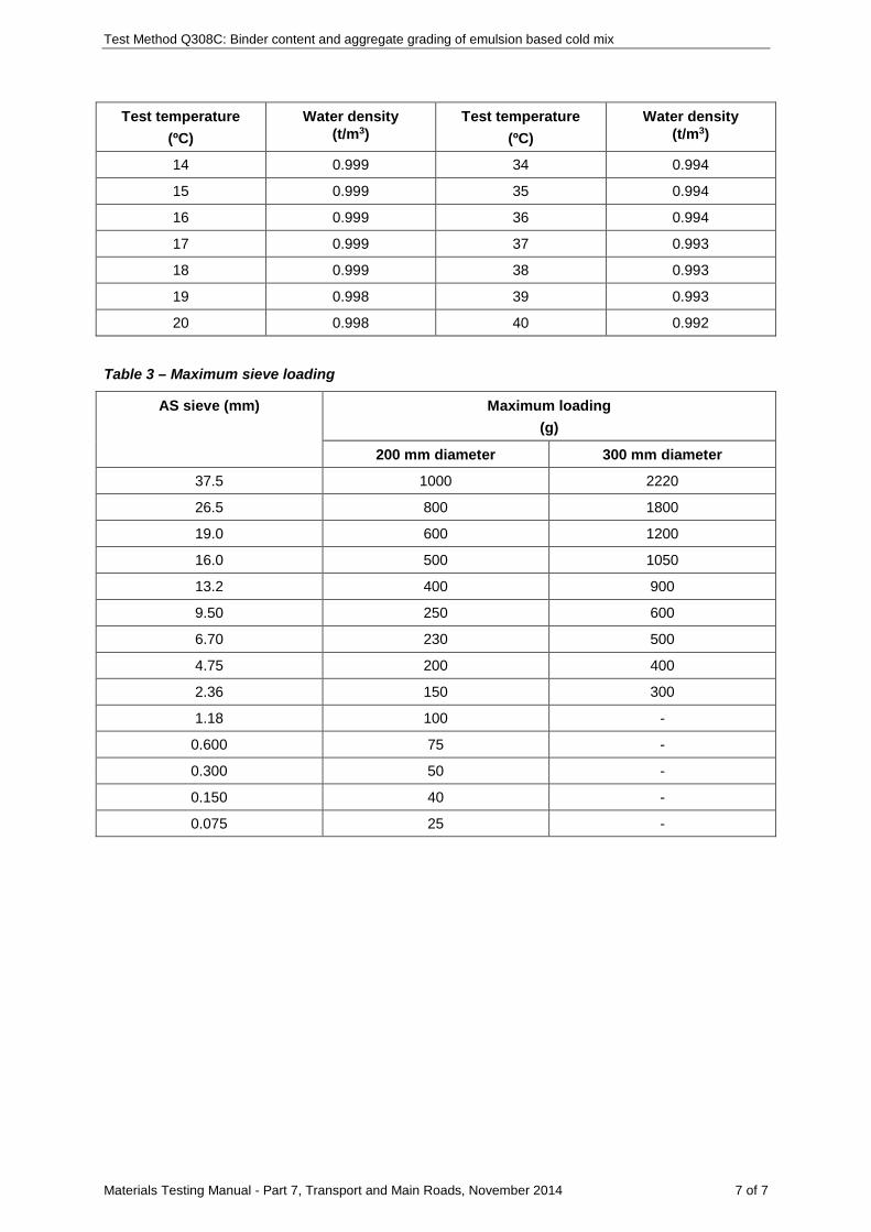
Test Method Q308C: Binder content and aggregate grading of emulsion based cold mix
Materials Testing Manual - Part 7, Transport and Main Roads, November 2014 7 of 7
Test temperature (ºC)
Water density (t/m3)
Test temperature (ºC)
Water density (t/m3)
14 0.999 34 0.994
15 0.999 35 0.994
16 0.999 36 0.994
17 0.999 37 0.993
18 0.999 38 0.993
19 0.998 39 0.993
20 0.998 40 0.992
Table 3 – Maximum sieve loading
AS sieve (mm) Maximum loading (g)
200 mm diameter 300 mm diameter
37.5 1000 2220
26.5 800 1800
19.0 600 1200
16.0 500 1050
13.2 400 900
9.50 250 600
6.70 230 500
4.75 200 400
2.36 150 300
1.18 100 -
0.600 75 -
0.300 50 -
0.150 40 -
0.075 25 -

Materials Testing Manual - Part 7, Transport and Main Roads, September 2017 1 of 1
Test Method Q308D: Binder content and aggregate grading of asphalt – ignition oven
This test shall be performed in accordance with Austroads Test Method AG:PT/T234: Asphalt binder content (ignition oven method) except as follows:
• add the following note to Clause 3a. "For certain heat sources, for example, infrared, an ignition oven temperature lower than 540°C may be applicable".
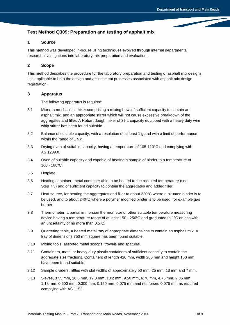
Materials Testing Manual - Part 7, Transport and Main Roads, November 2014 1 of 9
Test Method Q309: Preparation and testing of asphalt mix
1 Source
This method was developed in-house using techniques evolved through internal departmental research investigations into laboratory mix preparation and evaluation.
2 Scope
This method describes the procedure for the laboratory preparation and testing of asphalt mix designs. It is applicable to both the design and assessment processes associated with asphalt mix design registration.
3 Apparatus
The following apparatus is required:
3.1 Mixer, a mechanical mixer comprising a mixing bowl of sufficient capacity to contain an asphalt mix, and an appropriate stirrer which will not cause excessive breakdown of the aggregates and filler. A Hobart dough mixer of 35 L capacity equipped with a heavy duty wire whip stirrer has been found suitable.
3.2 Balance of suitable capacity, with a resolution of at least 1 g and with a limit of performance within the range of ± 5 g.
3.3 Drying oven of suitable capacity, having a temperature of 105-110°C and complying with AS 1289.0.
3.4 Oven of suitable capacity and capable of heating a sample of binder to a temperature of 160 - 180ºC.
3.5 Hotplate.
3.6 Heating container, metal container able to be heated to the required temperature (see Step 7.3) and of sufficient capacity to contain the aggregates and added filler.
3.7 Heat source, for heating the aggregates and filler to about 220ºC where a bitumen binder is to be used, and to about 240ºC where a polymer modified binder is to be used, for example gas burner.
3.8 Thermometer, a partial immersion thermometer or other suitable temperature measuring device having a temperature range of at least 150 - 250ºC and graduated to 1ºC or less with an uncertainty of no more than 0.5ºC.
3.9 Quartering table, a heated metal tray of appropriate dimensions to contain an asphalt mix. A tray of dimensions 750 mm square has been found suitable.
3.10 Mixing tools, assorted metal scoops, trowels and spatulas.
3.11 Containers, metal or heavy duty plastic containers of sufficient capacity to contain the aggregate size fractions. Containers of length 420 mm, width 280 mm and height 150 mm have been found suitable.
3.12 Sample dividers, riffles with slot widths of approximately 50 mm, 25 mm, 13 mm and 7 mm.
3.13 Sieves, 37.5 mm, 26.5 mm, 19.0 mm, 13.2 mm, 9.50 mm, 6.70 mm, 4.75 mm, 2.36 mm, 1.18 mm, 0.600 mm, 0.300 mm, 0.150 mm, 0.075 mm and reinforced 0.075 mm as required complying with AS 1152.
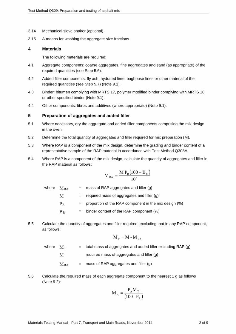
Test Method Q309: Preparation and testing of asphalt mix
Materials Testing Manual - Part 7, Transport and Main Roads, November 2014 2 of 9
3.14 Mechanical sieve shaker (optional).
3.15 A means for washing the aggregate size fractions.
4 Materials
The following materials are required:
4.1 Aggregate components: coarse aggregates, fine aggregates and sand (as appropriate) of the required quantities (see Step 5.6).
4.2 Added filler components: fly ash, hydrated lime, baghouse fines or other material of the required quantities (see Step 5.7) (Note 9.1).
4.3 Binder: bitumen complying with MRTS 17, polymer modified binder complying with MRTS 18 or other specified binder (Note 9.1).
4.4 Other components: fibres and additives (where appropriate) (Note 9.1).
5 Preparation of aggregates and added filler
5.1 Where necessary, dry the aggregate and added filler components comprising the mix design in the oven.
5.2 Determine the total quantity of aggregates and filler required for mix preparation (M).
5.3 Where RAP is a component of the mix design, determine the grading and binder content of a representative sample of the RAP material in accordance with Test Method Q308A.
5.4 Where RAP is a component of the mix design, calculate the quantity of aggregates and filler in the RAP material as follows:
( )4
RRRA 10
B100P MM −=
where MRA = mass of RAP aggregates and filler (g)
M = required mass of aggregates and filler (g)
PR = proportion of the RAP component in the mix design (%)
BR = binder content of the RAP component (%)
5.5 Calculate the quantity of aggregates and filler required, excluding that in any RAP component, as follows:
RAT M - M M =
where MT = total mass of aggregates and added filler excluding RAP (g)
M = required mass of aggregates and filler (g)
MRA = mass of RAP aggregates and filler (g)
5.6 Calculate the required mass of each aggregate component to the nearest 1 g as follows (Note 9.2):
( )R
TAA P-100
MPM =
Test Method Q309: Preparation and testing of asphalt mix
Materials Testing Manual - Part 7, Transport and Main Roads, November 2014 3 of 9
where AM = required mass of the aggregate component (g)
AP = proportion of the aggregate component in the mix design (%)
TM = total mass of aggregates and added filler excluding RAP(g)
PR = proportion of the RAP component in the mix design (%)
5.7 Calculate the required mass of each added filler component to the nearest 1 g as follows (Note 9.2):
( )R
TFF P-100
MPM =
where FM = required mass of the added filler component (g)
FP = proportion of the added filler component in the mix design (%)
TM = total mass of aggregates and added filler excluding RAP (g)
PR = proportion of the RAP component in the mix design (%)
5.8 Obtain the required masses of the aggregate components calculated in Step 5.6 by riffling and then combine these masses into a single sample. Added filler components are not introduced at this stage.
5.9 Sieve the combined sample to obtain the size fractions of Table 1 or Table 2 as appropriate using the procedure of Test Method Q103B, and place each sieved size fraction into a separate labelled aggregate container.
5.10 Wash each size fraction, excepting the material passing 0.075 mm, over a nest of two sieves comprising a sieve corresponding to the retained size fraction and the reinforced 0.075 mm sieve. Wash each size fraction until the wash water is clear.
5.11 Wash, dry and resieve all material retained on the 0.075 mm sieve over the sieves used in Step 5.9 in accordance with Test Method Q103B. Combine and thoroughly mix the material retained on each sieve with the corresponding size fraction obtained in Step 5.10.
5.12 Dry each size fraction in the drying oven (Note 9.3).
5.13 Determine the particle size distribution of each added filler component in accordance with Test Method Q103B.
5.14 Sieve the required mass of each added filler component into the relevant size fractions of Table 1 or Table 2 as appropriate using the procedure of Test Method Q103B, and place each sieved size fraction into a separate labelled filler container.
6 Calculation of mix component masses
6.1 Aggregates and added filler components
6.1.1 Record the grading of the mix (Note 9.4).
6.1.2 Calculate the percentage in each of the relevant size fractions ( SP ) of Table 1 or Table 2 as
appropriate for the mix grading.
Test Method Q309: Preparation and testing of asphalt mix
Materials Testing Manual - Part 7, Transport and Main Roads, November 2014 4 of 9
6.1.3 Calculate the required mass of each added filler component for each size fraction to the nearest 1 g as follows:
FS FFS
P MM100
=
where FSM = required mass of added filler size fraction (g)
FSP = proportion in the size fraction for the added filler determined from Step 5.13 (%)
FM = required mass of added filler calculated in Step 5.7 (g)
6.1.4 Calculate the total mass of added filler ( FSTM ) for each size fraction by summing the relevant
FSM values for all added filler components.
6.1.5 Calculate the required masses of each aggregate size fraction to the nearest 1 g as follows (Note 9.5):
100PMM
100MPM RSRA
FSTTS
AS −−=
where ASM = required mass of aggregate size fraction (g)
SP = proportion in the size fraction calculated in Step 6.1.2 (%)
TM = total mass of aggregate and added filler in the mix (g)
FSTM = total mass of added filler for the size fraction (g)
MRA = mass of RAP aggregates and filler calculated in Step 5.4 (g)
PRS = proportion in the size fraction for the RAP material determined from Step 5.3 (%)
6.2 Binder
Record the design binder content of the mix. Where required for dense graded asphalt, calculate the high and low tolerance binder contents by applying the appropriate maximum permitted variations of Table 3 to the design binder content.
7 Preparation of mix
7.1 Prepare the mixing bowl as follows:
7.1.1 Following use of the bowl in mixing aggregate, filler and binder components, empty the bowl and scrape adhering fines from the mixing area within the bowl while allowing a thin coating of binder to remain on the inside surface of the bowl.
7.1.2 Preheat the mixing bowl on the hotplate or in the oven.
7.2 Weigh the required masses of each size fraction calculated in Steps 6.1.3 and 6.1.5 for a particular mix into the heating container.
Test Method Q309: Preparation and testing of asphalt mix
Materials Testing Manual - Part 7, Transport and Main Roads, November 2014 5 of 9
7.3 Heat the container and contents to the appropriate temperature (Table 4). During the heating process, mix the contents periodically using the scoop to provide an even temperature distribution (Note 9.6).
7.4 Heat sufficient binder (and RAP material where applicable) for the mix in the oven to the appropriate temperature (Table 4).
7.5 Weigh the heated mixing bowl and record the mass ( 1m ) to the nearest 1 g.
7.6 Remove the container from the heat source and empty the contents carefully into the mixing bowl, ensuring that any fines adhering to the container are returned to the mix by brushing.
7.7 With the contents of the mixing bowl at the appropriate temperature (Table 4), weigh the mixing bowl and contents and record the mass ( 2m ) to the nearest 1 g.
7.8 Where RAP is a component of the mix design, calculate the required mass of RAP material for the mix to the nearest 1 g as follows:
( )( )R
12RR P-100
mmPM −=
where MR = required mass of RAP material (g)
PR = proportion of RAP in the mix (%)
m2 = mass of mixing bowl and contents (g)
m1 = mass of mixing bowl (g)
7.9 Remove the RAP material from the oven and add the required mass of representative RAP material (MR) to the mixing bowl.
7.10 Using a scoop or trowel, thoroughly stir the contents of the mixing bowl and then form a crater in the centre of the contents of the mixing bowl.
7.11 Calculate the required mass of binder for the mix to the nearest 1 g as follows (Note 9.7):
( )100
MBP100mmPM RR
B
12BB −
−−
=
where BM = required mass of binder (g)
BP = proportion of binder in the mix design (%)
2m = mass of mixing bowl and contents (g)
1m = mass of mixing bowl (g)
BR = binder content of the RAP material (%)
MR = required mass of RAP material (g)
7.12 Remove the binder from the oven, stir the binder and pour the required mass of binder ( BM )
into the crater.
7.13 Mechanically mix the contents of the mixing bowl for 90 seconds at the slowest speed.
Test Method Q309: Preparation and testing of asphalt mix
Materials Testing Manual - Part 7, Transport and Main Roads, November 2014 6 of 9
7.14 Stop the mixer and return any binder rich fines adhering to the stirrer and walls of the mixing bowl to the mix by scraping with the trowel or spatula.
7.15 Mechanically mix the contents of the mixing bowl for a further 90 seconds at the slowest speed.
7.16 Transfer the mix from the mixing bowl to the quartering table. Return any material adhering to the stirrer and mixing bowl to the mix by scraping with the trowel or spatula.
7.17 Obtain representative portions of the mix in accordance with Subsection 4.2 of Test Method Q301 and prepare test specimens in accordance with Section 5 of Test Method Q305, two for DG28 mix and four for all other mixes.
7.18 Remove any lip formed around the edges of each test specimen without damage to the test specimen.
7.19 Determine the compacted density of each test specimen in accordance with Test Method Q306C.
7.20 Where required, determine the stability, flow and stiffness of the test specimens in accordance with Test Method Q305.
7.21 Where required for open graded asphalt and stone mastic asphalt, prepare a 2 kg sample of mix in accordance with Steps 7.1 to 7.16 and test the mix for binder drainage in accordance with Test Method Q310.
7.22 Where required for open graded asphalt, test the four specimens for abrasion loss in accordance with Test Method Q313.
7.23 Prepare a 2 kg sample of mix in accordance with Steps 7.1 to 7.16 and determine the maximum density in accordance with Test Method Q307A.
7.24 Where required (excepting open graded asphalt), combine the mix from all test specimens, dry the mix, obtain a representative sample of the combined mix and determine the binder content and grading of the sample in accordance with Test Method Q308A.
7.25 Using the corresponding compacted density and maximum density values for each test specimen, determine the air voids for each test specimen in accordance with Test Method Q311.
7.26 Calculate the average air voids and average compacted density for the test specimens, and determine the remaining voids properties for the mix in accordance with Test Method Q311.
7.27 For tolerance mixes, if the test results for the mix meet the specified requirements within the maximum testing variation limits of Table 5, the mix shall be deemed to comply.
8 Reporting
Report all test results obtained for the mix.
9 Notes on method
9.1 Before handling fillers, binders, fibres and additives, the operator must consult the relevant Safety Data Sheet (SDS).
9.2 TM should normally be about 50 kg for asphalt nominal size < 20 mm and about 70 kg for
asphalt nominal size ≥ 20 mm.
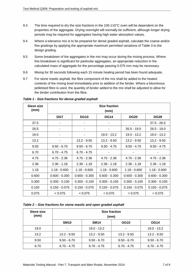
Test Method Q309: Preparation and testing of asphalt mix
Materials Testing Manual - Part 7, Transport and Main Roads, November 2014 7 of 9
9.3 The time required to dry the size fractions in the 105-110°C oven will be dependent on the properties of the aggregate. Drying overnight will normally be sufficient, although longer drying periods may be required for aggregates having high water absorption values.
9.4 Where a tolerance mix is to be prepared for dense graded asphalt, calculate the coarse and/or fine gradings by applying the appropriate maximum permitted variations of Table 3 to the design grading.
9.5 Some breakdown of the aggregates in the mix may occur during the mixing process. Where this breakdown is significant for particular aggregates, an appropriate reduction in the calculated mass of aggregate for the percentage passing 0.075 mm may be necessary.
9.6 Mixing for 30 seconds following each 15 minute heating period has been found adequate.
9.7 For stone mastic asphalt, the fibre component of the mix shall be added to the heated contents of the mixing bowl immediately prior to addition of the binder. Where a bituminous pelletised fibre is used, the quantity of binder added to the mix shall be adjusted to allow for the binder contribution from the fibre.
Table 1 - Size fractions for dense graded asphalt
Sieve size (mm)
Size fraction (mm)
DG7 DG10 DG14 DG20 DG28
37.5 - - - - 37.5 - 26.5
26.5 - - - 26.5 - 19.0 26.5 - 19.0
19.0 - - 19.0 - 13.2 19.0 - 13.2 19.0 - 13.2
13.2 - 13.2 - 9.50 13.2 - 9.50 13.2 - 9.50 13.2 - 9.50
9.50 9.50 - 6.70 9.50 - 6.70 9.50 - 4.75 9.50 - 4.75 9.50 - 4.75
6.70 6.70 - 4.75 6.70 - 4.75 - - -
4.75 4.75 - 2.36 4.75 - 2.36 4.75 - 2.36 4.75 - 2.36 4.75 - 2.36
2.36 2.36 - 1.18 2.36 - 1.18 2.36 - 1.18 2.36 - 1.18 2.36 - 1.18
1.18 1.18 - 0.600 1.18 - 0.600 1.18 - 0.600 1.18 - 0.600 1.18 - 0.600
0.600 0.600 - 0.300 0.600 - 0.300 0.600 - 0.300 0.600 - 0.300 0.600 - 0.300
0.300 0.300 - 0.150 0.300 - 0.150 0.300 - 0.150 0.300 - 0.150 0.300 - 0.150
0.150 0.150 - 0.075 0.150 - 0.075 0.150 - 0.075 0.150 - 0.075 0.150 - 0.075
0.075 < 0.075 < 0.075 < 0.075 < 0.075 < 0.075
Table 2 – Size fractions for stone mastic and open graded asphalt
Sieve size (mm)
Size fraction (mm)
SM10 SM14 OG10 OG14
19.0 - 19.0 - 13.2 - 19.0 - 13.2
13.2 13.2 - 9.50 13.2 - 9.50 13.2 - 9.50 13.2 - 9.50
9.50 9.50 - 6.70 9.50 - 6.70 9.50 - 6.70 9.50 - 6.70
6.70 6.70 - 4.75 6.70 - 4.75 6.70 - 4.75 6.70 - 4.75
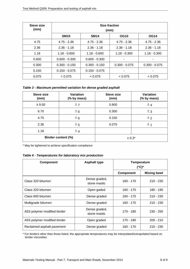
Test Method Q309: Preparation and testing of asphalt mix
Materials Testing Manual - Part 7, Transport and Main Roads, November 2014 8 of 9
Sieve size (mm)
Size fraction (mm)
SM10 SM14 OG10 OG14
4.75 4.75 - 2.36 4.75 - 2.36 4.75 - 2.36 4.75 - 2.36
2.36 2.36 - 1.18 2.36 - 1.18 2.36 - 1.18 2.36 - 1.18
1.18 1.18 - 0.600 1.18 - 0.600 1.18 - 0.300 1.18 - 0.300
0.600 0.600 - 0.300 0.600 - 0.300 - -
0.300 0.300 - 0.150 0.300 - 0.150 0.300 - 0.075 0.300 - 0.075
0.150 0.150 - 0.075 0.150 - 0.075 - -
0.075 < 0.075 < 0.075 < 0.075 < 0.075
Table 3 - Maximum permitted variation for dense graded asphalt
Sieve size (mm)
Variation (% by mass)
Sieve size (mm)
Variation (% by mass)
≥ 9.50 ± 7 0.600 ± 4
6.70 ± 6 0.300 ± 3
4.75 ± 6 0.150 ± 2
2.36 ± 5 0.075 ± 1
1.18 ± 4
Binder content (%) ± 0.3*
* May be tightened to achieve specification compliance
Table 4 - Temperatures for laboratory mix production
Component Asphalt type Temperature (°C)*
Component Mixing bowl
Class 320 bitumen Dense graded, stone mastic
160 - 170 210 - 230
Class 320 bitumen Open gaded 160 - 170 180 - 190
Class 600 bitumen Dense graded 160 - 170 210 - 230
Multigrade bitumen Dense graded 160 - 170 210 - 230
A5S polymer modified binder Dense graded, stone mastic
170 - 180 230 - 250
A5S polymer modified binder Open graded 170 - 180 200 - 210
Reclaimed asphalt pavement Dense graded 160 - 170 210 - 230
* For binders other than those listed, the appropriate temperatures may be interpolated/extrapolated based on binder viscosities
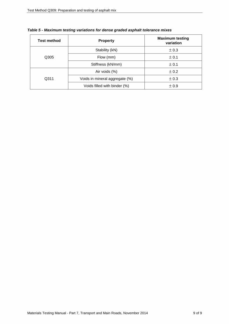
Test Method Q309: Preparation and testing of asphalt mix
Materials Testing Manual - Part 7, Transport and Main Roads, November 2014 9 of 9
Table 5 - Maximum testing variations for dense graded asphalt tolerance mixes
Test method Property Maximum testing variation
Q305
Stability (kN) ± 0.3
Flow (mm) ± 0.1
Stiffness (kN/mm) ± 0.1
Q311
Air voids (%) ± 0.2
Voids in mineral aggregate (%) ± 0.3
Voids filled with binder (%) ± 0.9
Materials Testing Manual - Part 7, Transport and Main Roads, November 2014 1 of 3
Test Method Q310: Binder drainage of asphalt mix
1 Source
This method applies the principles of AUSTROADS Bituminous Mixtures Test AG:PT/T235: Asphalt binder drain-off.
2 Scope
This method determines the propensity of asphalt to lose binder by the draindown effect. It involves heating a sample of representative mix in an oven at a temperature close to that at which the mix will normally be handled and determining the weight of binder remaining when the mix is emptied from the sample container.
3 Apparatus
Where appropriate, the working tolerances of particular apparatus are contained in Table 1.
The following apparatus is required:
3.1 Oven of suitable capacity, capable of maintaining the test temperature (Note 8.1).
3.2 Balance of suitable capacity, having a resolution of at least 0.1 g and with a limit of performance within the range of ± 0.5 g.
3.3 Beaker, glass beaker of 1 litre capacity.
3.4 Beaker cover, a watchglass or can lid of suitable size.
3.5 Filter funnel, a glass filter funnel.
3.6 Metal tray, capable of holding at least 1 kg of mix.
3.7 Heat resistant gloves (Note 8.2).
4 Materials
The following materials are required:
4.1 Filter paper, Whatman No. 1 or equivalent.
4.2 Mineral turpentine (Note 8.3).
5 Procedure
The procedure shall be as follows:
5.1 Weigh a 1 litre beaker and record the mass to the nearest 0.1 g ( 1m ) (Note 8.2).
5.2 Prepare a representative sample of 1000 ± 100 g of mix in accordance with Subsection 4.2 of Test Method Q301 and place it in the beaker.
5.3 Weigh the beaker and mix and record the mass to the nearest 0.1 g ( 2m ).
5.4 Cover the beaker and place it in the oven for 60 ± 1 minutes.
5.5 Remove the beaker from the oven with minimal disturbance of the contents.
5.6 Remove the cover and immediately upend the beaker over the metal tray. Allow the mix to empty from the beaker without the use of any shaking or vibration for 10 ± 1 seconds and then return the beaker to the upright position.
Test Method Q310: Binder drainage of asphalt mix
Materials Testing Manual - Part 7, Transport and Main Roads, November 2014 2 of 3
5.7 Weigh the beaker and record the mass to the nearest 0.1 g ( 3m ).
5.8 Add sufficient mineral turpentine to the beaker to dissolve the binder.
5.9 Weigh a filter paper and record the mass to the nearest 0.1 g ( 4m ).
5.10 Filter the solution and transfer the entire contents of the beaker to the filter paper using additional mineral turpentine as required.
5.11 Wash the residue on the filter paper with mineral turpentine until it is free of binder.
5.12 Dry the filter paper ensuring no loss of residue.
5.13 Weigh the filter paper and residue and record the mass to the nearest 0.1 g ( 5m ).
6 Calculations
Calculate the binder drainage of the sample to the nearest 0.01% as follows:
( )( )
3 4 1 5
2 1
100 m +m -m -mBD=
m -m
where BD = binder drainage (%)
3m = mass of beaker, binder and residue (g)
4m = mass of filter paper (g)
1m = mass of beaker (g)
5m = mass of filter paper and residue (g)
2m = mass of beaker and mix (g)
7 Reporting
Report the binder drainage of the sample to the nearest 0.01%.
8 Notes on method
8.1 The test temperature is intended to approximate the expected average maximum handling temperature of the mix in the field. Test temperatures of 150ºC and 175ºC are appropriate for mixes containing bitumen binders and polymer modified binders respectively. If the expected average maximum handling temperature is known to vary significantly from these temperatures, then a different test temperature should be used.
8.2 All equipment including gloves used for holding hot apparatus must be very clean. The sensitivity of the test means that a smear of binder on the beaker can substantially affect the result.
8.3 Before handling mineral turpentine, the operator must consult the relevant Safety Data Sheet (SDS).

Test Method Q310: Binder drainage of asphalt mix
Materials Testing Manual - Part 7, Transport and Main Roads, November 2014 3 of 3
Table 1 – Working tolerances for apparatus
Apparatus Dimension Tolerance
Oven
Test Temperature (ºC) Note 8.1 ± 5
Materials Testing Manual - Part 7, Transport and Main Roads, March 2016 1 of 4
Test Method Q311: Voids properties for compacted asphalt
1 Source
This method applies the principles of AS/NZS 2891.8: Voids and volumetric properties of compacted asphalt mixes. It differs from this Australian Standard in that binder absorption is determined either directly or indirectly from water absorption as well as via calculation from values of aggregate particle density, binder density and asphalt maximum density.
2 Scope
This method describes the procedure for calculation of the voids relationships for a sample of compacted asphalt. It requires prior determination of the compacted density, maximum density and binder content of the sample, the density of the binder and the binder absorption of the aggregate.
3 Procedure
The procedure shall be as follows:
3.1 Determine the compacted density of the sample ( CD ) in accordance with Test
Method Q306A, Q306B, Q306C, Q306D or Q306E as appropriate, and record the value to the nearest 0.001 3t/m .
3.2 Determine the maximum density of the sample ( MD ) in accordance with Test Method Q307A
and record the value to the nearest 0.001 3t/m .
3.3 Determine the binder content of the sample (B) in accordance with Test Method Q308A or Q308D as appropriate and record the value to the nearest 0.01%.
3.4 Determine the density of the binder in the sample ( BD ) in accordance with Test Method Q331
and record the value at 25ºC to the nearest 0.001 t/m³ (Note 6.1).
3.5 Determine the binder absorption of the aggregate either in accordance with Test Method Q211 or Q316, or using an established binder absorption/water absorption relationship, and record the value to the nearest 0.01% (Notes 6.2, 6.3 and 6.4). Where binder absorption is determined using a binder absorption/water absorption relationship, determine the water absorption of the coarse fraction (retained 4.75 mm) ( cWA ) and fine fraction (passing
4.75 mm and retained 0.075 mm) ( fWA ) in accordance with Test Methods AS 1141.6.1 and
AS 1141.5 respectively, and record these values to the nearest 0.01%.
4 Calculations
4.1 Calculate the percentage by volume of air voids in the sample to the nearest 0.1 as follows:
C
M
DAV=100 1-D
where AV = air voids (%)
CD = compacted density of the sample ( 3t/m )
MD = maximum density of the sample ( 3t/m )
Test Method Q311: Voids properties for compacted asphalt
Materials Testing Manual - Part 7, Transport and Main Roads, March 2016 2 of 4
4.2 Calculate the percentage by volume of effective binder in the sample to the nearest 0.1 using the appropriate calculation as follows (Note 6.4):
4.2.1 For binder absorption of the aggregate determined using Test Method Q211 or an established binder absorption/water absorption relationship:
C aB a
B
D BbV = B-b +D 100
where BV = effective binder volume (%)
CD = compacted density of the sample (t/m³)
BD = density of the binder (t/m³)
B = binder content of the sample (%)
ab =
binder absorption of the aggregate (% by mass of aggregate)
4.2.2 For binder absorption of the aggregate determined using Test Method Q316:
( )CB m
B
DV = B-bD
where BV = effective binder volume (%)
CD = compacted density of the sample (t/m³)
BD = density of the binder (t/m³)
B = binder content of the sample (%)
mb = binder absorption of the aggregate (% by mass of mix)
4.3 Calculate the percentage by volume of voids in the mineral aggregate in the sample to the nearest 0.1 as follows:
BVMA=AV+V
where VMA = voids in the mineral aggregate (%)
AV = air voids (%)
BV
= effective binder volume (%)
4.4 Calculate the percentage by volume of voids filled with binder in the sample to the nearest 0.1 as follows:
B100VVFB=VMA
where VFB = voids filled with binder (%)
BV
= effective binder volume (%)
VMA = voids in the mineral aggregate (%)
Test Method Q311: Voids properties for compacted asphalt
Materials Testing Manual - Part 7, Transport and Main Roads, March 2016 3 of 4
4.5 Where a number of tests have been performed on a lot, calculate the maximum and minimum characteristic percentage by volume of air voids as detailed in Test Method Q020.
5 Reporting
Report the following values:
5.1 Air voids to the nearest 0.1%.
5.2 Voids in the mineral aggregate to the nearest 0.1%.
5.3 Voids filled with binder to the nearest 0.5%.
5.4 The minimum characteristic percentage by volume of air voids as detailed in Test Method Q020, if required.
5.5 The maximum characteristic percentage by volume of air voids as detailed in Test Method Q020, if required.
6 Notes on method
6.1 Where the density of the binder is unknown and circumstances do not allow its determination, a value of 1.040 t/m³ may be assumed.
6.2 Where the binder absorption of the aggregate in the sample is to be obtained using Test Method Q211 but is known from previous determination, further testing in accordance with Q211 is unnecessary.
6.3 Where the binder absorption of the aggregate in the sample is to be obtained using an established binder absorption/water absorption relationship, the following calculation may be used:
ab =0.55WA
where ab = binder absorption of the aggregate (% by mass of aggregate)
WA = water absorption of the aggregate (%)
WA may be calculated using either of the following which assume the filler component to have an absorption value equivalent to the average of the coarse and fine aggregate absorption values.
a) Where water absorption values are available for the coarse and fine fractions of the combined aggregate, calculate the water absorption of the aggregate as detailed in Test Method Q214.
c c f f
c f
P WA +P WAWA=P +P
where WA = water absorption of the aggregate (%)
cP = proportion of coarse aggregate (%)
cWA = water absorption of coarse aggregate (%)
fP = proportion of fine aggregate (%)
fWA = water absorption of fine aggregate (%)
Test Method Q311: Voids properties for compacted asphalt
Materials Testing Manual - Part 7, Transport and Main Roads, March 2016 4 of 4
b) Where water absorption values are available for the coarse and fine fractions of each individual aggregate component of the combined aggregate, calculate the water absorption as follows:
N
i ii=1
WA= P WA∑
where WA = water absorption of the aggregate (%)
iP = proportion of the ith aggregate component in the combined aggregate
(%)
iWA = water absorption of ith aggregate component calculated using Test
Method Q214(%)
n =
number of aggregate components
6.4 Where binder absorption of the aggregate is determined using Test Method Q211 or an established binder absorption/water absorption relationship, it is expressed as a percentage by mass of aggregate. To convert from percentage by mass of aggregate to percentage by mass of mix, the following calculation may be used:
am a
Bbb =b -100
where mb = binder absorption of the aggregate (% by mass of mix)
ab = binder absorption of the aggregate (% by mass of aggregate)
B = binder content of the sample (%)
Materials Testing Manual - Part 7, Transport and Main Roads, November 2014 1 of 3
Test Method Q312: Extraction of binder from road surfacings
1 Source
This method is based on a procedure developed from research performed by the Australian Road Research Board (Dickinson, E.l. "A Method of Following the Hardening of Paving Bitumens in Service", ARRB Research report ARR66, 1976).
2 Scope
This method describes the procedure for the extraction of binder from samples taken from sprayed seal or asphalt surfacings. The binder is prepared in a manner which allows measurement of its viscosity using suitable apparatus.
3 Apparatus
The following apparatus is required:
3.1 Test oven, as described in Test Method AS 2341.13.
3.1.1 Oven of suitable capacity, having a temperature of 105-110°C and complying with AS 1289.0.
3.2 Flowmeter, capable of measuring a gas flow rate of 4 L/min.
3.3 Sample bottles, as described in Test Method AS 2341.13.
3.4 Heating and mixing assembly, as described in Test Method AS 2341.13, and including the teflon dish.
3.5 Balance of suitable capacity, having a resolution of at least 0.1 g and with a limit of performance within the range of ± 0.5 g.
3.6 Centrifuge, capable of holding at least two 50 mL aliquots and achieving 3000 rpm rotation.
3.7 Freezer, of sufficient capacity to contain the teflon dish.
3.8 Measuring cylinders, two measuring cylinders of 25 mL and 100 mL capacity, graduated in 1 mL increments.
3.9 Filter funnel, a glass filter funnel.
3.10 Beakers, four beakers of 250 mL capacity.
3.11 Sieve, 0.075 mm complying with AS 1152.
3.12 Implements, for subsampling the test material, for example, knife or screwdriver for sprayed seal, metal trowel for asphalt, and for removing the binder from the sample bottles and teflon dish, for example, scalpel or spatula.
4 Materials
The following materials are required:
4.1 Toluene, AR grade (Note 6.1).
4.2 Aluminium foil.
4.3 Filter paper, Whatman No. 41 or equivalent.
4.4 Carbon dioxide supply, regulated to 4 ± 0.5 L/min.
Test Method Q312: Extraction of binder from road surfacings
Materials Testing Manual - Part 7, Transport and Main Roads, November 2014 2 of 3
5 Procedure
The procedure shall be as follows:
5.1 Preheat the test oven to 100°C.
5.2 Place the sample of road surfacing in the drying oven for approximately 15 minutes to soften the sample.
5.3 For a sprayed seal sample, prise a sufficient number of stone pieces from the seal to yield a representative subsample of about 100 g.
5.4 For an asphalt sample, obtain a representative subsample of about 50 g by coning and quartering.
5.5 Place the subsample into a 250 mL beaker and add about 100 mL of toluene by measuring cylinder (Note 6.2).
5.6 Cover the beaker with aluminium foil and allow it to stand for 1 hour.
5.7 Decant the contents of the beaker over the 0.075 mm sieve into a second 250 mL beaker.
5.8 Transfer the bitumen solution in the beaker to the centrifuge tubes and centrifuge the solution at approximately 3000 rpm for 15 minutes.
5.9 Pour the centrifuged solution in the centrifuge tubes into a third 250 mL beaker and filter this solution into the remaining 250 mL beaker.
5.10 Determine the mass of each of the four sample bottles.
5.11 Transfer 15 to 20 mL of the filtered solution to each sample bottle by measuring cylinder.
5.12 Turn the test oven off and place the sample bottles into the carriage of the test oven (Note 6.3).
5.13 Turn the test oven on and start the carriage rotation and carbon dioxide flow. Adjust the carbon dioxide flow to obtain a flow rate of 4 ± 0.5 L/min through the oven's outlet orifice.
5.14 After 45 minutes, turn the test oven off and remove the sample bottles.
5.15 Weigh each sample bottle and record the mass to the nearest 0.1 g (Note 6.4).
5.16 Scrape as much as possible of the binder film from the four sample bottles and transfer the scrapings to the teflon dish.
5.17 Bring the heating and mixing assembly to a temperature of 200 ± 5°C, and attach the carbon dioxide feed.
5.18 Place the teflon dish within the heating and mixing assembly and adjust the carbon dioxide flow rate to about 4 L/min.
5.19 After 5 minutes, remove the teflon dish from the heating and mixing assembly and immediately place it in the freezer.
5.20 Remove the teflon dish from the freezer and lever the homogenised binder from the dish using a warmed spatula (Note 6.5).
6 Notes on method
6.1 Before handling toluene, the operator must consult the relevant Safety Data Sheet (SDS).
6.2 Addition of toluene to dissolve the binder and extraction of binder from the toluene/bitumen solution must be performed on the same day.

Test Method Q312: Extraction of binder from road surfacings
Materials Testing Manual - Part 7, Transport and Main Roads, November 2014 3 of 3
6.3 While the test oven can accommodate up to eight sample bottles, only four sample bottles are used for each sample. When binder from one sample only is to be extracted, the remaining four spaces shall be filled with empty bottles.
6.4 The mass of binder in each of the four sample bottles shall be from 0.3 g to 0.8 g. A binder film of mass less than 0.3 g may have been oxidised during the extraction process, while a binder film of mass greater than 0.8 g may not have been evaporated for sufficient time to remove all of the toluene. Where the mass of binder recovered in each sample bottle falls outside this mass range, the procedure shall be repeated.
6.5 Where the viscosity of the homogenised binder is not to be determined on the same day as the extraction, the teflon dish containing the homogenised sample shall be covered with aluminium foil and stored in the freezer.

Materials Testing Manual - Part 7, Transport and Main Roads, November 2014 1 of 1
Test Method Q313: Abrasion loss of asphalt
This test shall be performed in accordance with Austroads Test Method AG:PT/T236 - Asphalt particle loss.
Materials Testing Manual - Part 7, Transport and Main Roads, November 2014 1 of 1
Test Method Q314: Relative compaction of asphalt
1 Source
This method is based on AS 2891.14.5: Field density tests – density ratio of compacted asphalt.
2 Scope
This method describes the procedure for determining the relative compaction of asphalt. It is determined as the ratio of the compacted density and the maximum density values for the asphalt expressed as a percentage.
3 Procedure
The procedure shall be as follows:
3.1 Determine the compacted density of the sample ( CD ) in accordance with Test
Method Q306A, Q306B, Q306C, Q306D or Q306E as appropriate, and record the value to the nearest 0.001 3t/m .
3.2 Determine the maximum density of the sample ( MD ) in accordance with Test Method Q307A
and record the value to the nearest 0.001 3t/m .
4 Calculations
4.1 Calculate the relative compaction to the nearest 0.1% as follows:
C
M
100DRC=D
where RC = relative compaction (%)
CD = compacted density ( 3t/m )
MD = maximum density ( 3t/m )
4.2 Where a number of tests have been performed on a lot, calculate the minimum and/or maximum characteristic relative compaction as detailed in Test Method Q020.
5 Reporting
5.1 Report the relative compaction to the nearest 0.1%.
5.2 If required, report the minimum and/or maximum characteristic relative compaction as detailed in Test Method Q020.
Materials Testing Manual - Part 7, Transport and Main Roads, March 2016 1 of 5
Test Method Q315: Sensitivity of asphalt to water
1 Source
This method applies the principles of Austroads Test Method AG:PT/T232: Stripping potential of asphalt – Tensile strength ratio.
2 Scope
This method describes the procedure for the determination of the stripping potential of asphalt in the presence of water. The effect of water on the indirect tensile strength of moisture conditioned specimens is expressed as a ratio of the indirect tensile strength determined from dry specimens. It is applicable to asphalt having a nominal size no greater than 20 mm.
3 Apparatus
The following apparatus is required:
3.1 Mechanical mixer and accessories to prepare the asphalt in accordance with Test Method AS 2891.2.1.
3.2 Compaction equipment required to compact the asphalt specimens in accordance with either Test Method AS 2891.2.2 or Test Method Q305.
3.3 Marshall testing machine, breaking head and associated measurement system to load an asphalt specimen at 51 ± 3 mm per minute.
3.4 Loading blocks, as described in Test Method AS 2891.13.1.
3.5 Balance of suitable capacity, having a resolution of at least 0.1 g and with a limit of performance within the range of ± 0.5 g.
3.6 Freezer, maintained at a temperature of –18 ± 3°C and of sufficient capacity to contain three test specimens.
3.7 Constant temperature environment, a cabinet or room maintained at a temperature of 25 ± 1°C.
3.8 Water baths, two baths maintained at temperatures of 25 ± 1°C and 60 ± 1°C and of sufficient capacity to contain three test specimens.
3.9 Vacuum system, capable of applying a partial vacuum of 13 – 67 kPa absolute pressure.
3.10 Vacuum dessicator.
3.11 Thermometer, a partial or total immersion thermometer or other suitable temperature measuring device with a temperature range of at least 0 to 40°C and graduated to 1°C or less with an uncertainty of no more than 0.5°C.
3.12 Thermometer, a partial or total immersion thermometer or other suitable temperature measuring device with a temperature range of at least -20 to 0°C and graduated to 1°C or less with an uncertainty of no more than 0.5°C.
3.13 Callipers.
3.14 Measuring cylinder, of 10 mL capacity.
Test Method Q315: Sensitivity of asphalt to water
Materials Testing Manual - Part 7, Transport and Main Roads, March 2016 2 of 5
4 Materials
The following materials are required:
4.1 Plastic cling wrap, thick leak proof plastic bags and masking tape, suitable for sealing asphalt specimens.
4.2 Cloth, a damp cloth which has been soaked in water and then wrung out.
5 Procedure
The procedure shall be as follows:
5.1 Obtain an 8 kg sample of either plant production mix sampled as detailed in Test Method Q301, or laboratory manufactured mix prepared using the components and nominated binder content and grading for the mix design in accordance with the procedures described in Test Methods Q309 and AS 2891.2.1.
5.2 Prepare six 100 mm diameter compacted specimens to a height of 65 ± 1 mm and an air voids content of 8 ± 1% using the required mass of laboratory manufactured mix compacted in accordance with Test Method AS 2891.2.2 or Test Method Q305.
5.3 Determine the maximum density of the remainder of the laboratory manufactured mix in accordance with Test Method Q307A.
5.4 Measure the height (H) and diameter (D) of each specimen using the callipers and record the values to the nearest 1 mm.
5.5 Weigh each specimen and record the mass to the nearest 0.1 g ( 1m ).
5.6 Determine the compacted density of each specimen in accordance with Test Method Q306B or Q306C, and record the volume of the specimen ( dV ) (Note 8.1).
5.7 Determine the air voids of each specimen in accordance with Test Method Q311 (Note 8.2).
5.8 Divide the six specimens into two sets of three specimens such that each set has similar average air voids.
5.9 Select one set of three specimens, place the specimens on their sides under water in the vacuum desiccator and record the temperature of the water to the nearest 1°C.
5.10 Apply vacuum to partially saturate the specimens to between 55% and 80% saturation (Note 8.3).
5.11 Dry each of the three specimens to a surface-dry condition by quickly blotting the surface of the specimen with the damp cloth (Note 8.4).
5.12 Weigh each of three specimens and record the mass to the nearest 0.1 g ( 2m ).
5.13 Wrap each of the three specimens in several layers of plastic cling wrap.
5.14 Place each wrapped specimen into a separate plastic bag containing 10 mL water and seal the bag using masking tape.
5.15 Place the plastic bags containing the specimens in the freezer for 18 ± 1 hours, ensuring that the wrapped specimens are not in contact with each other.
5.16 Transfer the three specimens from the freezer to the 60°C water bath. As soon as possible after placement in the water bath, remove the plastic bag and wrapping from the specimens, and allow the specimens to soak in the bath for 24 ± 1 hours.
Test Method Q315: Sensitivity of asphalt to water
Materials Testing Manual - Part 7, Transport and Main Roads, March 2016 3 of 5
5.17 Transfer the three specimens to the 25°C water bath, ensuring they are not in contact and leave them in the bath for 120 ± 5 minutes (Note 8.5).
5.18 Remove a specimen from the water bath and immediately test it in accordance with the procedure described in Sections 5 and 6 of Test Method Q305, except that loading blocks shall be used instead of the breaking head. Record the maximum load for each specimen to the nearest 0.1 kN.
5.19 Repeat Step 5.18 for the two remaining moisture conditioned specimens.
5.20 Condition the remaining set of three dry specimens in the 25°C constant temperature environment for 120 ± 5 minutes (Note 8.6).
5.21 Remove a specimen from the constant temperature environment and immediately test it in accordance with the procedure described in Sections 5 and 6 of Test Method Q305, except that loading blocks shall be used instead of the breaking head. Record the maximum load for each specimen to the nearest 0.1 kN.
5.22 Repeat Step 5.21 for the two remaining dry specimens.
6 Calculations
Calculate as follows:
6.1 Calculate the degree of saturation for each of the three moisture conditioned specimens as follows:
2 1
w d
10000(m -m )SP=AVD V
where SP = degree of saturation of partially saturated specimens (%)
2m
= mass of partially saturated specimen (g)
1m
= mass of dry specimen (g)
AV = air voids of specimen (%)
wD
= density of water in the vacuum desiccator (t/m³) (Table 1)
dV
= volume of specimen (cm³)
6.2 Calculate the tensile strength for each of the dry and moisture conditioned specimens using as follows:
62P10S=πHD
where S = tensile strength of specimen (kPa)
P = maximum load for specimen (kN)
H = height of specimen (mm)
D = diameter of specimen (mm)
Test Method Q315: Sensitivity of asphalt to water
Materials Testing Manual - Part 7, Transport and Main Roads, March 2016 4 of 5
6.3 Calculate the average tensile strengths for the three soaked specimens ( wS ) and for the three
dry specimens ( dS ) to the nearest 10 kPa.
6.4 Determine the tensile strength ratio as follows:
w
d
100STSR=S
where TSR = tensile strength ratio (%)
wS = average tensile strength of the moisture conditioned specimens (kPa)
dS = average tensile strength of the dry specimens (kPa)
7 Reporting
Report the following:
7.1 The air voids of each specimen to the nearest 0.1%.
7.2 The degree of saturation of each partially saturated specimen to the nearest 0.1%.
7.3 The average tensile strengths for the moisture conditioned specimens and for the dry specimens to the nearest 10 kPa.
7.4 The tensile strength ratio to the nearest 1%.
8 Notes on method
8.1 If Test Method Q306B is used to determine compacted density, the following shall apply:
a) The period of immersion for each specimen shall be 3 to 5 minutes instead of a minimum of 5 minutes.
b) The three specimens to be tested dry (Step 5.8) shall be allowed to air dry to the original dry mass prior to conditioning in the 25°C constant temperature environment (Step 5.20).
8.2 If the air voids for the compacted specimens falls outside the range of 8 ± 1%, preparation of the mix shall be repeated and an adjusted number of gyratory cycles or Marshall blows shall be used to produce specimens within the required air voids range.
8.3 Partial saturation between 55% and 80% will normally require about 30 seconds under vacuum. A partial vacuum of 13 – 67 kPa absolute pressure is approximately equivalent to a -88 to -34 kPa reading on a vacuum gauge at sea level.
8.4 The purpose of blotting with the damp cloth is to remove excess water beaded on the surface. It is not intended that water is drawn from the void spaces so the blotting must be done lightly and as quickly as possible.
8.5 To ensure that the conditioning period does not exceed 125 minutes prior to testing (see Steps 5.18 to 5.19), it may be necessary to stagger transfer of the specimens to the water bath.
8.6 To ensure that the conditioning period does not exceed 125 minutes prior to testing (see Steps 5.21 to 5.22), it may be necessary to stagger transfer of the specimens to the constant temperature environment.
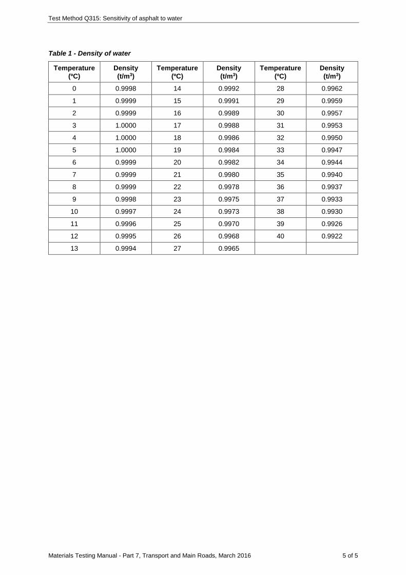
Test Method Q315: Sensitivity of asphalt to water
Materials Testing Manual - Part 7, Transport and Main Roads, March 2016 5 of 5
Table 1 - Density of water
Temperature (ºC)
Density (t/m3)
Temperature (ºC)
Density (t/m3)
Temperature (ºC)
Density (t/m3)
0 0.9998 14 0.9992 28 0.9962
1 0.9999 15 0.9991 29 0.9959
2 0.9999 16 0.9989 30 0.9957
3 1.0000 17 0.9988 31 0.9953
4 1.0000 18 0.9986 32 0.9950
5 1.0000 19 0.9984 33 0.9947
6 0.9999 20 0.9982 34 0.9944
7 0.9999 21 0.9980 35 0.9940
8 0.9999 22 0.9978 36 0.9937
9 0.9998 23 0.9975 37 0.9933
10 0.9997 24 0.9973 38 0.9930
11 0.9996 25 0.9970 39 0.9926
12 0.9995 26 0.9968 40 0.9922
13 0.9994 27 0.9965
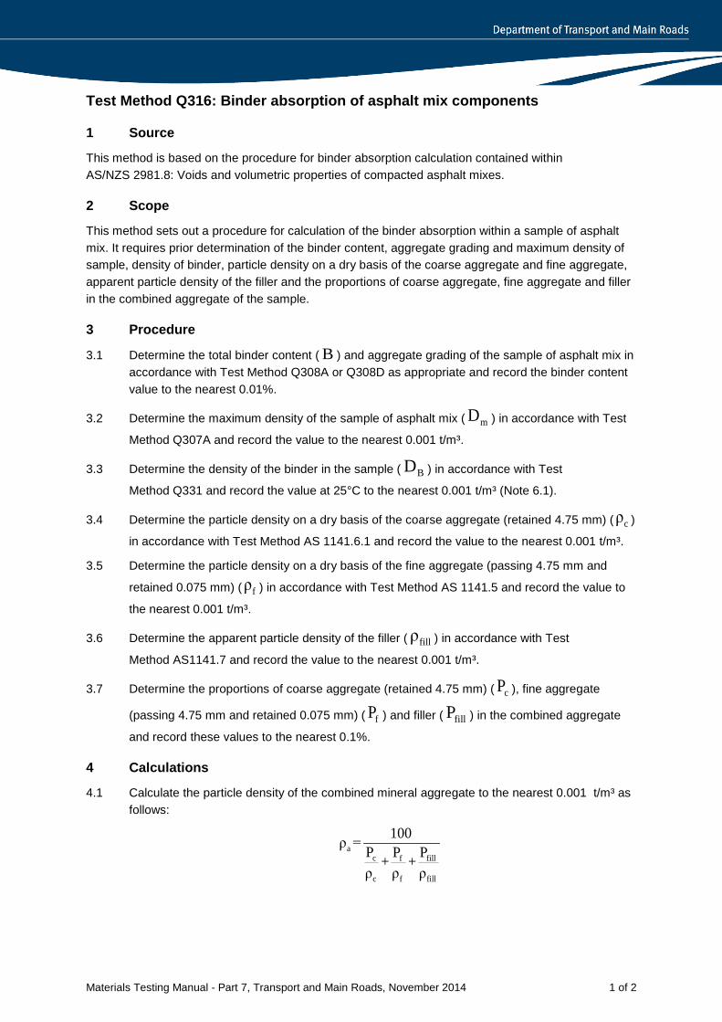
Materials Testing Manual - Part 7, Transport and Main Roads, November 2014 1 of 2
Test Method Q316: Binder absorption of asphalt mix components
1 Source
This method is based on the procedure for binder absorption calculation contained within AS/NZS 2981.8: Voids and volumetric properties of compacted asphalt mixes.
2 Scope
This method sets out a procedure for calculation of the binder absorption within a sample of asphalt mix. It requires prior determination of the binder content, aggregate grading and maximum density of sample, density of binder, particle density on a dry basis of the coarse aggregate and fine aggregate, apparent particle density of the filler and the proportions of coarse aggregate, fine aggregate and filler in the combined aggregate of the sample.
3 Procedure
3.1 Determine the total binder content ( B ) and aggregate grading of the sample of asphalt mix in accordance with Test Method Q308A or Q308D as appropriate and record the binder content value to the nearest 0.01%.
3.2 Determine the maximum density of the sample of asphalt mix ( mD ) in accordance with Test
Method Q307A and record the value to the nearest 0.001 t/m³.
3.3 Determine the density of the binder in the sample ( BD ) in accordance with Test
Method Q331 and record the value at 25°C to the nearest 0.001 t/m³ (Note 6.1).
3.4 Determine the particle density on a dry basis of the coarse aggregate (retained 4.75 mm) ( cρ )
in accordance with Test Method AS 1141.6.1 and record the value to the nearest 0.001 t/m³.
3.5 Determine the particle density on a dry basis of the fine aggregate (passing 4.75 mm and
retained 0.075 mm) ( fρ ) in accordance with Test Method AS 1141.5 and record the value to
the nearest 0.001 t/m³.
3.6 Determine the apparent particle density of the filler ( fillρ ) in accordance with Test
Method AS1141.7 and record the value to the nearest 0.001 t/m³.
3.7 Determine the proportions of coarse aggregate (retained 4.75 mm) ( cP ), fine aggregate
(passing 4.75 mm and retained 0.075 mm) ( fP ) and filler ( fillP ) in the combined aggregate
and record these values to the nearest 0.1%.
4 Calculations
4.1 Calculate the particle density of the combined mineral aggregate to the nearest 0.001 t/m³ as follows:
ac f fill
c f fill
100ρ = P P P+ +ρ ρ ρ
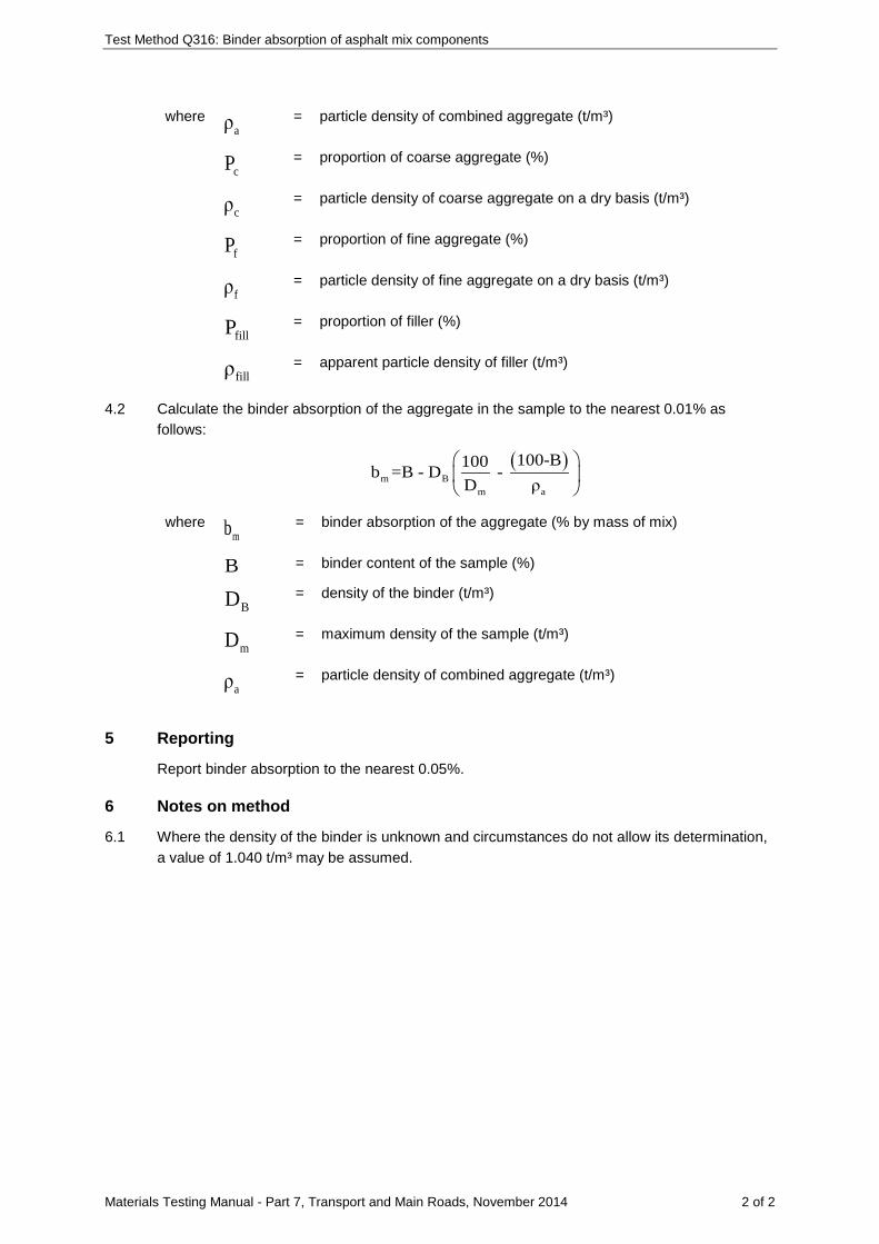
Test Method Q316: Binder absorption of asphalt mix components
Materials Testing Manual - Part 7, Transport and Main Roads, November 2014 2 of 2
where aρ = particle density of combined aggregate (t/m³)
cP = proportion of coarse aggregate (%)
cρ = particle density of coarse aggregate on a dry basis (t/m³)
fP = proportion of fine aggregate (%)
fρ = particle density of fine aggregate on a dry basis (t/m³)
fillP = proportion of filler (%)
fillρ = apparent particle density of filler (t/m³)
4.2 Calculate the binder absorption of the aggregate in the sample to the nearest 0.01% as follows:
( )m B
m a
100-B100b =B - D - D ρ
where mb
= binder absorption of the aggregate (% by mass of mix)
B = binder content of the sample (%)
BD
= density of the binder (t/m³)
mD
= maximum density of the sample (t/m³)
aρ
= particle density of combined aggregate (t/m³)
5 Reporting
Report binder absorption to the nearest 0.05%.
6 Notes on method
6.1 Where the density of the binder is unknown and circumstances do not allow its determination, a value of 1.040 t/m³ may be assumed.
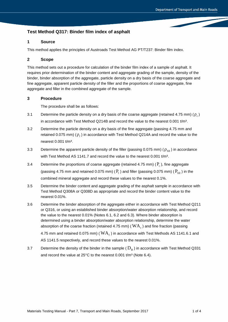
Materials Testing Manual - Part 7, Transport and Main Roads, September 2017 1 of 4
Test Method Q317: Binder film index of asphalt
1 Source
This method applies the principles of Austroads Test Method AG PT/T237: Binder film index.
2 Scope
This method sets out a procedure for calculation of the binder film index of a sample of asphalt. It requires prior determination of the binder content and aggregate grading of the sample, density of the binder, binder absorption of the aggregate, particle density on a dry basis of the coarse aggregate and fine aggregate, apparent particle density of the filler and the proportions of coarse aggregate, fine aggregate and filler in the combined aggregate of the sample.
3 Procedure
The procedure shall be as follows:
3.1 Determine the particle density on a dry basis of the coarse aggregate (retained 4.75 mm) ( cρ )
in accordance with Test Method Q214B and record the value to the nearest 0.001 t/m³.
3.2 Determine the particle density on a dry basis of the fine aggregate (passing 4.75 mm and retained 0.075 mm) ( fρ ) in accordance with Test Method Q214A and record the value to the
nearest 0.001 t/m³.
3.3 Determine the apparent particle density of the filler (passing 0.075 mm) ( fillρ ) in accordance
with Test Method AS 1141.7 and record the value to the nearest 0.001 t/m³.
3.4 Determine the proportions of coarse aggregate (retained 4.75 mm) ( cP ), fine aggregate
(passing 4.75 mm and retained 0.075 mm) ( fP ) and filler (passing 0.075 mm) ( fillP ) in the
combined mineral aggregate and record these values to the nearest 0.1%.
3.5 Determine the binder content and aggregate grading of the asphalt sample in accordance with Test Method Q308A or Q308D as appropriate and record the binder content value to the nearest 0.01%.
3.6 Determine the binder absorption of the aggregate either in accordance with Test Method Q211 or Q316, or using an established binder absorption/water absorption relationship, and record the value to the nearest 0.01% (Notes 6.1, 6.2 and 6.3). Where binder absorption is determined using a binder absorption/water absorption relationship, determine the water absorption of the coarse fraction (retained 4.75 mm) ( cWA ) and fine fraction (passing
4.75 mm and retained 0.075 mm) ( fWA ) in accordance with Test Methods AS 1141.6.1 and
AS 1141.5 respectively, and record these values to the nearest 0.01%.
3.7 Determine the density of the binder in the sample ( BD ) in accordance with Test Method Q331
and record the value at 25°C to the nearest 0.001 t/m³ (Note 6.4).
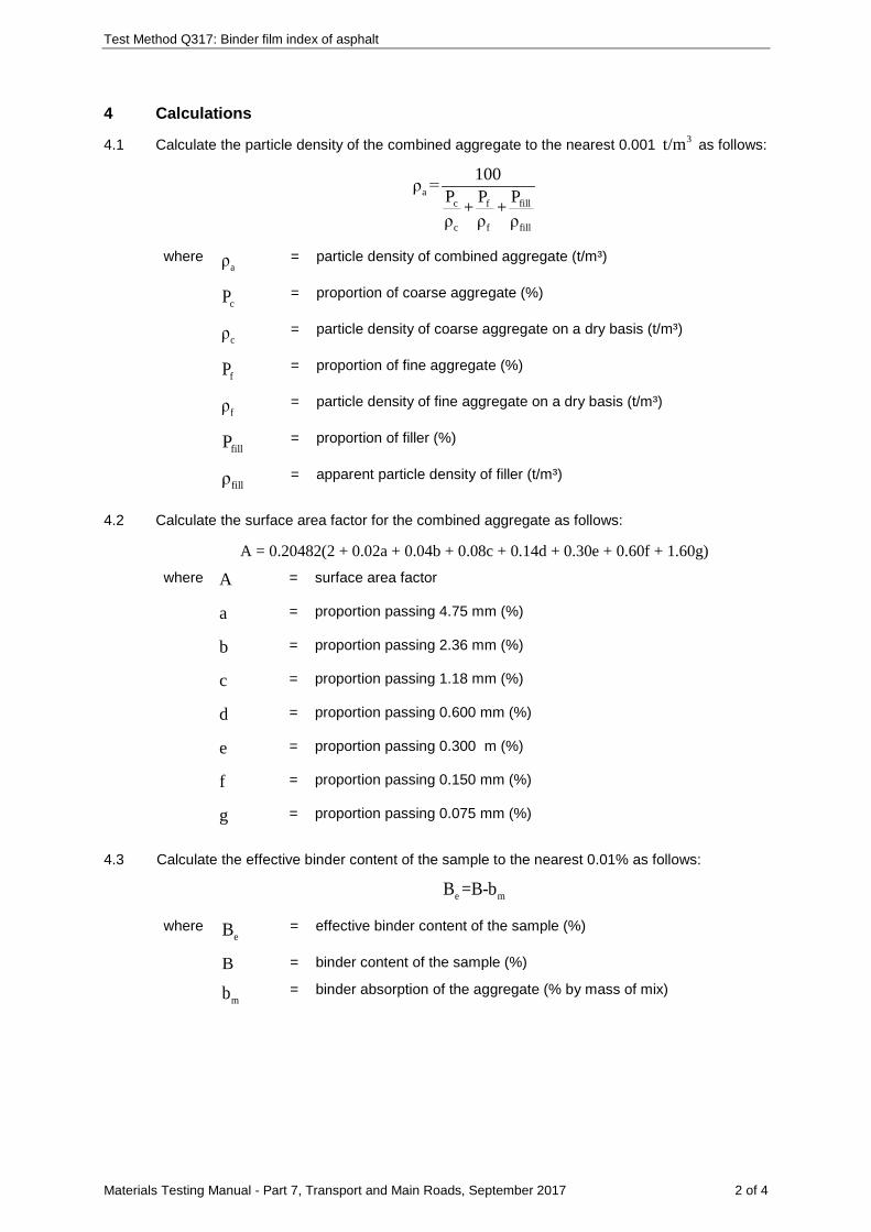
Test Method Q317: Binder film index of asphalt
Materials Testing Manual - Part 7, Transport and Main Roads, September 2017 2 of 4
4 Calculations
4.1 Calculate the particle density of the combined aggregate to the nearest 0.001 3t/m as follows:
ac f fill
c f fill
100ρ = P P P+ +ρ ρ ρ
where aρ
= particle density of combined aggregate (t/m³)
cP
= proportion of coarse aggregate (%)
cρ
= particle density of coarse aggregate on a dry basis (t/m³)
fP
= proportion of fine aggregate (%)
fρ
= particle density of fine aggregate on a dry basis (t/m³)
fillP
= proportion of filler (%)
fillρ
= apparent particle density of filler (t/m³)
4.2 Calculate the surface area factor for the combined aggregate as follows:
A = 0.20482(2 + 0.02a + 0.04b + 0.08c + 0.14d + 0.30e + 0.60f + 1.60g) where A = surface area factor
a = proportion passing 4.75 mm (%)
b = proportion passing 2.36 mm (%)
c = proportion passing 1.18 mm (%)
d = proportion passing 0.600 mm (%)
e = proportion passing 0.300 m (%)
f = proportion passing 0.150 mm (%)
g = proportion passing 0.075 mm (%)
4.3 Calculate the effective binder content of the sample to the nearest 0.01% as follows:
e mB =B-b
where eB = effective binder content of the sample (%)
B = binder content of the sample (%)
mb = binder absorption of the aggregate (% by mass of mix)
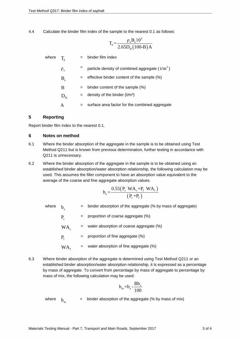
Test Method Q317: Binder film index of asphalt
Materials Testing Manual - Part 7, Transport and Main Roads, September 2017 3 of 4
4.4 Calculate the binder film index of the sample to the nearest 0.1 as follows:
( )3
a eF
B
ρ B 10T =2.65D 100-B A
where FT
= binder film index
aρ = particle density of combined aggregate ( 3t/m )
eB = effective binder content of the sample (%)
B = binder content of the sample (%)
BD = density of the binder (t/m³)
A = surface area factor for the combined aggregate
5 Reporting
Report binder film index to the nearest 0.1.
6 Notes on method
6.1 Where the binder absorption of the aggregate in the sample is to be obtained using Test Method Q211 but is known from previous determination, further testing in accordance with Q211 is unnecessary.
6.2 Where the binder absorption of the aggregate in the sample is to be obtained using an established binder absorption/water absorption relationship, the following calculation may be used. This assumes the filler component to have an absorption value equivalent to the average of the coarse and fine aggregate absorption values.
( )( )
c c f fa
c f
0.55 P WA +P WAb =
P +P
where ab = binder absorption of the aggregate (% by mass of aggregate)
cP = proportion of coarse aggregate (%)
cWA = water absorption of coarse aggregate (%)
fP = proportion of fine aggregate (%)
fWA = water absorption of fine aggregate (%)
6.3 Where binder absorption of the aggregate is determined using Test Method Q211 or an established binder absorption/water absorption relationship, it is expressed as a percentage by mass of aggregate. To convert from percentage by mass of aggregate to percentage by mass of mix, the following calculation may be used:
am a
Bbb =b -100
where mb = binder absorption of the aggregate (% by mass of mix)

Test Method Q317: Binder film index of asphalt
Materials Testing Manual - Part 7, Transport and Main Roads, September 2017 4 of 4
ab = binder absorption of the aggregate (% by mass of aggregate)
B = binder content of the sample (%)
6.4 Where the density of the binder is unknown and circumstances do not allow its determination, a value of 1.040 t/m³ may be assumed.
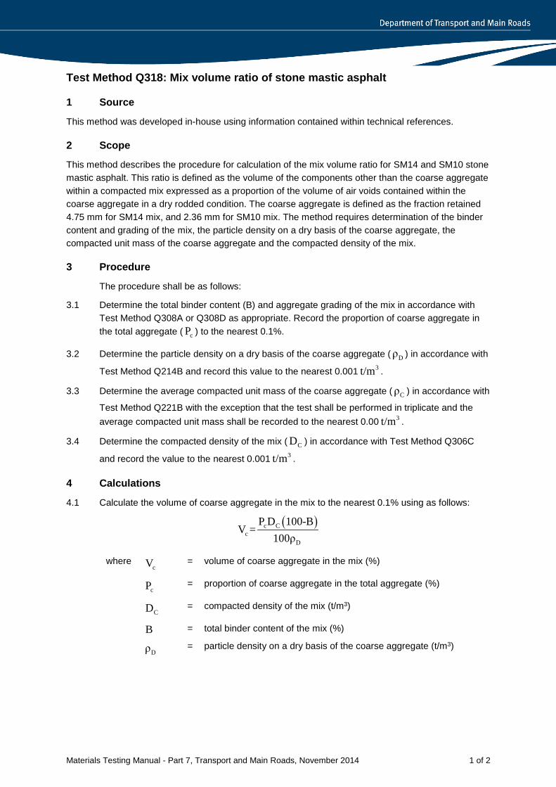
Materials Testing Manual - Part 7, Transport and Main Roads, November 2014 1 of 2
Test Method Q318: Mix volume ratio of stone mastic asphalt
1 Source
This method was developed in-house using information contained within technical references.
2 Scope
This method describes the procedure for calculation of the mix volume ratio for SM14 and SM10 stone mastic asphalt. This ratio is defined as the volume of the components other than the coarse aggregate within a compacted mix expressed as a proportion of the volume of air voids contained within the coarse aggregate in a dry rodded condition. The coarse aggregate is defined as the fraction retained 4.75 mm for SM14 mix, and 2.36 mm for SM10 mix. The method requires determination of the binder content and grading of the mix, the particle density on a dry basis of the coarse aggregate, the compacted unit mass of the coarse aggregate and the compacted density of the mix.
3 Procedure
The procedure shall be as follows:
3.1 Determine the total binder content (B) and aggregate grading of the mix in accordance with Test Method Q308A or Q308D as appropriate. Record the proportion of coarse aggregate in the total aggregate ( cP ) to the nearest 0.1%.
3.2 Determine the particle density on a dry basis of the coarse aggregate ( Dρ ) in accordance with
Test Method Q214B and record this value to the nearest 0.001 3t/m .
3.3 Determine the average compacted unit mass of the coarse aggregate ( Cρ ) in accordance with
Test Method Q221B with the exception that the test shall be performed in triplicate and the average compacted unit mass shall be recorded to the nearest 0.00 3t/m .
3.4 Determine the compacted density of the mix ( CD ) in accordance with Test Method Q306C
and record the value to the nearest 0.001 3t/m .
4 Calculations
4.1 Calculate the volume of coarse aggregate in the mix to the nearest 0.1% using as follows:
( )c Cc
D
P D 100-BV =
100ρ
where cV = volume of coarse aggregate in the mix (%)
cP = proportion of coarse aggregate in the total aggregate (%)
CD = compacted density of the mix (t/m3)
B = total binder content of the mix (%)
Dρ = particle density on a dry basis of the coarse aggregate (t/m3)
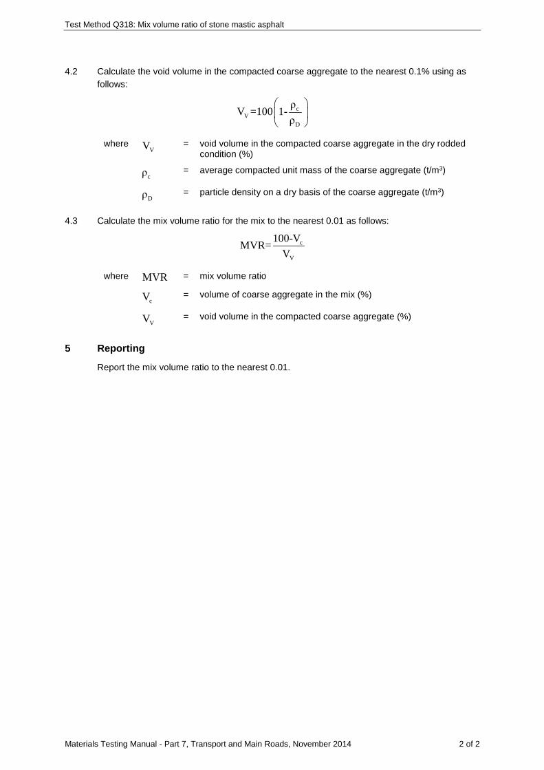
Test Method Q318: Mix volume ratio of stone mastic asphalt
Materials Testing Manual - Part 7, Transport and Main Roads, November 2014 2 of 2
4.2 Calculate the void volume in the compacted coarse aggregate to the nearest 0.1% using as follows:
cV
D
ρV =100 1-ρ
where VV = void volume in the compacted coarse aggregate in the dry rodded
condition (%)
cρ = average compacted unit mass of the coarse aggregate (t/m3)
Dρ = particle density on a dry basis of the coarse aggregate (t/m3)
4.3 Calculate the mix volume ratio for the mix to the nearest 0.01 as follows:
c
V
100-VMVR=V
where MVR = mix volume ratio
cV = volume of coarse aggregate in the mix (%)
VV = void volume in the compacted coarse aggregate (%)
5 Reporting
Report the mix volume ratio to the nearest 0.01.
Materials Testing Manual - Part 7, Transport and Main Roads, November 2014 1 of 8
Test Method Q319: Manufacture of laboratory slab specimens for wheel tracker testing - segmental wheel compactor
1 Source
This method applies the principles of Austroads Asphalt Test AST 05: Sample preparation - Compaction of asphalt slabs suitable for characterisation.
2 Scope
This method describes the procedure for the laboratory manufacture of asphalt slab specimens using a segmental wheel compactor for wheel tracker testing. It may also be applied in part to the manufacture of asphalt slab specimens from plant mix. Three slab specimens are prepared for each mix.
3 Apparatus
The following apparatus is required:
3.1 Segmental wheel compactor, comprising the following (Note 8.1):
3.1.1 Compaction device, capable of applying a loading of 1000 to 30 000 N to within 500 N. The compaction device shall be in the form of a freely rotating wheel segment of diameter 1200 ± 200 mm. The foot of the compaction device shall have an arc length of 300 mm and a width of 300 mm. The compaction foot shall be able to be moved vertically and set to a specified height above the base of the compaction mould using a setting block. It shall have the option of vibratory compaction and shall be of sufficient rigidity that it will not deform under load over the operating range.
3.1.2 Compaction table, having an oscillating speed of 10 to 25 oscillations per minute adjustable to within 1 oscillation per minute, and a travel of 200 to 450 mm adjustable to within 5 mm. The table shall have provision to firmly attach the compaction mould.
3.1.3 Compaction moulds, three metal moulds of internal dimensions 300 mm length, 300 mm width and of sufficient depth to accommodate the slab specimen mix prior to compaction. Each mould shall be fitted with two removable end plates of dimensions 300 mm length and 125 mm height attached to the top of two opposite sides of the mould. The mould shall be equipped with electrical heating to allow it to be heated to the compaction temperature.
3.1.4 Lifting device, to move a compaction mould (with or without mix) to and from the compaction table.
3.2 Mixer, a mechanical mixer comprising a mixing bowl of sufficient capacity to contain the mix to be used in manufacture of three slab specimens, and an appropriate stirrer which will not cause excessive breakdown of the aggregates. A mixer of 35 L capacity has been found suitable.
3.3 Balance of suitable capacity, having a resolution of at least 1 g and with a limit of performance within the range of ± 5 g.
3.4 Container, fitted with an overflow and filled with clean water to the overflow. The container shall be of suitable dimensions to allow a slab specimen to be completely immersed without contacting any part of the container.
3.5 Suspension device, cable or wire frame to suspend a slab specimen on its side.
3.6 Oven, of suitable capacity and maintained at a temperature of 150°C.
Test Method Q319: Manufacture of laboratory slab specimens for wheel tracker testing - segmental wheel compactor
Materials Testing Manual - Part 7, Transport and Main Roads, November 2014 2 of 8
3.7 Quartering table, metal tray (preferably heated) of appropriate dimensions to contain the mix for three slab specimens. A tray of dimensions 1 m square has been found suitable.
3.8 Oven or hotplate, capable of heating a sample of binder to a temperature of 150-180°C.
3.9 A means for heating the aggregates and added filler to about 210°C (for example, gas burner).
3.10 Heating container(s), metal container(s) able to be heated to at least 210°C and of sufficient capacity to contain the aggregates and added filler.
3.11 Transfer container, metal container of sufficient capacity to transfer the entire mix from the mixer to the quartering table.
3.12 Thermometer, a partial immersion thermometer or other suitable temperature measuring device having a temperature range of up to 250°C and with a resolution of 1°C or less with an uncertainty of no more than 2.0°C.
3.13 Fan, an electric fan to disperse vapours emanating from the sealant during the curing period.
3.14 Mixing tools (for example, metal scoops, trowels, spatulas).
3.15 Marking medium, to identify the slab specimen.
4 Materials
The following materials are required:
4.1 Sealant, acetic cure silicone sealant of known density to the nearest 0.001 t/m³ (Note 8.3)
4.2 Asphalt release agent (Note 8.2).
4.3 Aggregate components: coarse aggregates, fine aggregates and sand (as appropriate) of the required quantities (see Step 5.2).
4.4 Added filler components: fly ash, hydrated lime, baghouse fines or other material of the required quantities (see Step 5.2) (Note 8.2).
4.5 Binder: bitumen complying with MRTS 17, polymer modified binder complying with MRTS 18 or other specified binder (Note 8.2).
4.6 Other components: fibres and additives (where appropriate) (Note 8.2).
5 Preparation of mix
The procedure shall be as follows:
5.1 Dry sufficient quantities of the aggregate and added filler components of the mix design to provide the required total mass of aggregates and added filler (Note 8.2).
5.2 Calculate the required mass of each aggregate and added filler component as follows:
R TR
P MM100
=
where RM = mass of aggregate or added filler component (g)
RP = proportion of the aggregate or added filler in the mix design (%)
TM = total mass of aggregates and added filler (g)
Test Method Q319: Manufacture of laboratory slab specimens for wheel tracker testing - segmental wheel compactor
Materials Testing Manual - Part 7, Transport and Main Roads, November 2014 3 of 8
5.3 Combine the required masses of the aggregates and added filler and then transfer representative portions of the combined materials into one or more heating containers (Note 8.4).
5.4 Heat the container(s) and contents to the appropriate temperature using the gas burner or other means (Table 1). During the heating process, mix the contents periodically using a metal scoop to provide an even temperature distribution (Note 8.5).
5.5 Heat the binder in the oven or on the hotplate to the appropriate temperature (Table 1).
5.6 Remove a container from the heating source, determine the mass of the container and contents ( C1m ).
5.7 Empty the contents of the container carefully into the mixer, determine the mass of the container ( C2m ).
5.8 Calculate the mass of the contents of the container as follows:
C C2 C1m m m= −
where Cm = mass of contents of heating container (g)
C2m = mass of heating container and contents (g)
C1m = mass of heating container (g)
5.9 Repeat Steps 5.6 to 5.8 for the remaining containers.
5.10 Calculate the total mass of the contents from all heating containers ( CM ) by summing the
individual masses calculated in Steps 5.8 and 5.9.
5.11 Where fibre is a component of the mix design, undertake the following:
5.11.1 Calculate the mass of fibre for the mix as follows:
F CF
P MM100
=
where FM = mass of fibre (g)
FP = proportion of fibre in the mix (%)
CM = total mass of contents (g)
5.11.2 Add the required mass of fibre to the contents of the mixer, and distribute the fibre uniformly throughout the contents by mixing for about 15 seconds.
5.12 Calculate the mass of binder for the mix as follows:
B CB
B
P MM =100-P
where BM = required mass of binder (g)
BP = proportion of binder in the mix (%) (Note 8.6)
CM = total mass of contents (g)
Test Method Q319: Manufacture of laboratory slab specimens for wheel tracker testing - segmental wheel compactor
Materials Testing Manual - Part 7, Transport and Main Roads, November 2014 4 of 8
5.13 Pour the required mass of binder ( BM ) into a crater formed in the centre of the contents of
the mixer.
5.14 Mix the contents of the mixer by hand for about 30 seconds using a trowel. Return any material adhering to the trowel to the mixer.
5.15 Mechanically mix the contents for 90 seconds at the slowest speed.
5.16 Stop the mixer and return any binder rich fines adhering to the walls of the mixer to the mix by scraping with a trowel or spatula.
5.17 Mechanically mix the contents for a further 90 seconds at the slowest speed.
5.18 Using the transfer container, transfer the entire mix from the mixer to the quartering table. Return any material adhering to the mixer or transfer container to the mix by scraping with the trowel or spatula.
5.19 Calculate the mass of mix required for each slab specimen as follows:
( )MD V 100-AVM=
100
where BM = mass of mix (g)
BP = maximum density of mix (t/m³) (Note 8.7)
V = volume of specimen mould (cm³)
AV = target air voids (%)
5.20 Prepare the mix in accordance with Clause 4.2 of Test Method Q301 to obtain representative portions for three slab specimens and for mix testing as detailed in Test Methods Q307A and Q308A/Q308D.
6 Preparation of slab specimen
Prepare each slab specimen portion as follows:
6.1 Condition the portion of mix allocated for the slab specimen in the oven for one hour at 150°C (Note 8.8).
6.2 Assemble the mould and fix one of the end plates to the mould.
6.3 Preheat the mould to the compaction temperature and preheat the compaction foot (Note 8.9).
6.4 Apply a thin layer of asphalt release agent to the inside surfaces of the mould and to the bottom of the compaction foot.
6.5 Insert the appropriate setting block into the slab compactor to set the thickness of the slab specimen and locate the compaction foot at a height corresponding to just below the top of the mould end plate.
6.6 Transfer the mix portion to the mould, screed it flat without segregation using a trowel and level the mix.
6.7 With the compaction table at the end of its forward cycle, transfer the mould and sample to the compaction table using the lifting device, inserting the side opposite the end plate first.
6.8 Fix the mould to the compaction table.
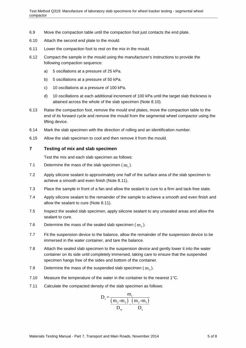
Test Method Q319: Manufacture of laboratory slab specimens for wheel tracker testing - segmental wheel compactor
Materials Testing Manual - Part 7, Transport and Main Roads, November 2014 5 of 8
6.9 Move the compaction table until the compaction foot just contacts the end plate.
6.10 Attach the second end plate to the mould.
6.11 Lower the compaction foot to rest on the mix in the mould.
6.12 Compact the sample in the mould using the manufacturer's instructions to provide the following compaction sequence:
a) 5 oscillations at a pressure of 25 kPa.
b) 5 oscillations at a pressure of 50 kPa.
c) 10 oscillations at a pressure of 100 kPa.
d) 10 oscillations at each additional increment of 100 kPa until the target slab thickness is attained across the whole of the slab specimen (Note 8.10).
6.13 Raise the compaction foot, remove the mould end plates, move the compaction table to the end of its forward cycle and remove the mould from the segmental wheel compactor using the lifting device.
6.14 Mark the slab specimen with the direction of rolling and an identification number.
6.15 Allow the slab specimen to cool and then remove it from the mould.
7 Testing of mix and slab specimen
Test the mix and each slab specimen as follows:
7.1 Determine the mass of the slab specimen ( 1m ).
7.2 Apply silicone sealant to approximately one half of the surface area of the slab specimen to achieve a smooth and even finish (Note 8.11).
7.3 Place the sample in front of a fan and allow the sealant to cure to a firm and tack-free state.
7.4 Apply silicone sealant to the remainder of the sample to achieve a smooth and even finish and allow the sealant to cure (Note 8.11).
7.5 Inspect the sealed slab specimen, apply silicone sealant to any unsealed areas and allow the sealant to cure.
7.6 Determine the mass of the sealed slab specimen ( 2m ).
7.7 Fit the suspension device to the balance, allow the remainder of the suspension device to be immersed in the water container, and tare the balance.
7.8 Attach the sealed slab specimen to the suspension device and gently lower it into the water container on its side until completely immersed, taking care to ensure that the suspended specimen hangs free of the sides and bottom of the container.
7.9 Determine the mass of the suspended slab specimen ( 3m ).
7.10 Measure the temperature of the water in the container to the nearest 1°C.
7.11 Calculate the compacted density of the slab specimen as follows:
( ) ( )1
c2 3 2 1
w s
mD =m -m m -m
-D D
Test Method Q319: Manufacture of laboratory slab specimens for wheel tracker testing - segmental wheel compactor
Materials Testing Manual - Part 7, Transport and Main Roads, November 2014 6 of 8
where CD = compacted density of slab specimen (t/m³)
1m = mass of slab specimen (g)
2m = mass of sealed slab specimen (g)
3m = mass of immersed sealed slab specimen (g)
WD = density of water at test temperature (t/m³) (Table 2)
SD = density of silicone sealant (t/m³)
7.12 Repeat Steps 7.1 to 7.11 for the remaining slab specimens.
7.13 Determine the maximum density of the mix in accordance with Test Method Q307A using the designated test portion.
7.14 Determine the binder content and grading of the mix in accordance with Test Method Q308A or Q308D using the designated test portion.
7.15 Using the values for compacted density and maximum density obtained in Steps 7.11 and 7.13, calculate the air voids in the slab specimen in accordance with Test Method Q311.
7.16 Accept the slab specimen for further preparation and testing subject to the following:
a) The air void content is within ± 0.5% of the target air voids.
b) The binder content and grading of the mix agree with the target values within the tolerances specified in Table 3.
7.17 Store the slab specimen at a temperature not exceeding 30°C on a flat non-deforming surface of dimensions not less than those of the slab specimen.
8 Notes on method
8.1 The BP Slab Compactor satisfies the requirements of the segmental wheel compactor.
8.2 Before handling the silicone sealant, flyash, hydrated lime, fibre, the operator must consult the relevant Material Safety Data Sheet (MSDS).
8.3 The total mass of aggregates and added filler may be estimated from the quantity of mix required to prepare three slab specimens and perform testing for binder content, grading and maximum density. This quantity of mix will vary according to the required thickness of the slab specimen and the maximum density of the mix. A mix quantity of 35 to 50 kg will normally be required.
8.4 Some breakdown of the aggregates in the mix may occur during the mixing process. Where this breakdown is significant for particular aggregates, an appropriate adjustment to the calculated required masses of the aggregates and added filler may be necessary.
8.5 Mixing for 30 seconds following each 15 minute heating period has been found adequate.
8.6 Depending on the particular mix prepared and the nature of the mechanical mixer, it may be necessary to increase the proportion of binder in the mix by up to 0.15% to allow for binder losses on the stirrer and mixing bowl.
8.7 Where the maximum density of the mix is unknown, prior preparation and testing of a trial mix for maximum density measurement may be necessary. Otherwise, an estimate of the maximum density based on previous experience may be used.
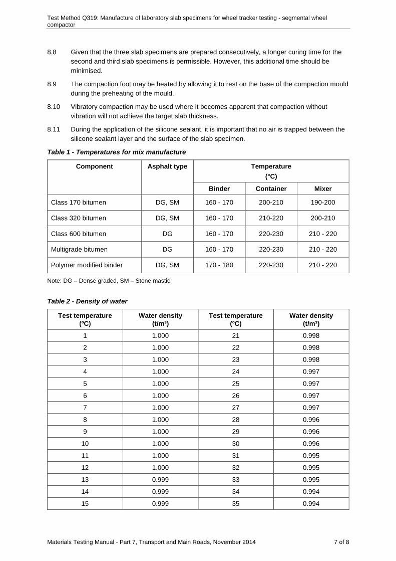
Test Method Q319: Manufacture of laboratory slab specimens for wheel tracker testing - segmental wheel compactor
Materials Testing Manual - Part 7, Transport and Main Roads, November 2014 7 of 8
8.8 Given that the three slab specimens are prepared consecutively, a longer curing time for the second and third slab specimens is permissible. However, this additional time should be minimised.
8.9 The compaction foot may be heated by allowing it to rest on the base of the compaction mould during the preheating of the mould.
8.10 Vibratory compaction may be used where it becomes apparent that compaction without vibration will not achieve the target slab thickness.
8.11 During the application of the silicone sealant, it is important that no air is trapped between the silicone sealant layer and the surface of the slab specimen.
Table 1 - Temperatures for mix manufacture
Component Asphalt type Temperature (°C)
Binder Container Mixer
Class 170 bitumen DG, SM 160 - 170 200-210 190-200
Class 320 bitumen DG, SM 160 - 170 210-220 200-210
Class 600 bitumen DG 160 - 170 220-230 210 - 220
Multigrade bitumen DG 160 - 170 220-230 210 - 220
Polymer modified binder DG, SM 170 - 180 220-230 210 - 220
Note: DG – Dense graded, SM – Stone mastic
Table 2 - Density of water
Test temperature (ºC)
Water density (t/m³)
Test temperature (ºC)
Water density (t/m³)
1 1.000 21 0.998
2 1.000 22 0.998
3 1.000 23 0.998
4 1.000 24 0.997
5 1.000 25 0.997
6 1.000 26 0.997
7 1.000 27 0.997
8 1.000 28 0.996
9 1.000 29 0.996
10 1.000 30 0.996
11 1.000 31 0.995
12 1.000 32 0.995
13 0.999 33 0.995
14 0.999 34 0.994
15 0.999 35 0.994
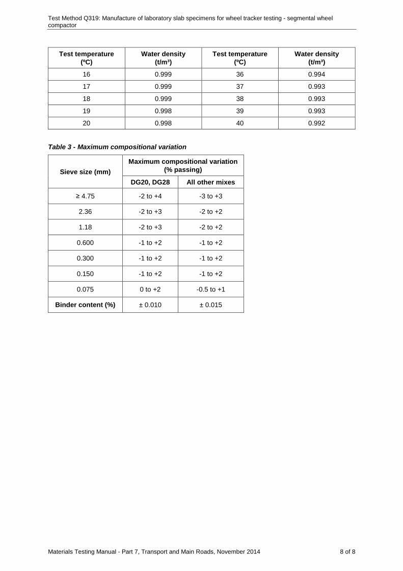
Test Method Q319: Manufacture of laboratory slab specimens for wheel tracker testing - segmental wheel compactor
Materials Testing Manual - Part 7, Transport and Main Roads, November 2014 8 of 8
Test temperature (ºC)
Water density (t/m³)
Test temperature (ºC)
Water density (t/m³)
16 0.999 36 0.994
17 0.999 37 0.993
18 0.999 38 0.993
19 0.998 39 0.993
20 0.998 40 0.992
Table 3 - Maximum compositional variation
Sieve size (mm) Maximum compositional variation
(% passing)
DG20, DG28 All other mixes
≥ 4.75 -2 to +4 -3 to +3
2.36 -2 to +3 -2 to +2
1.18 -2 to +3 -2 to +2
0.600 -1 to +2 -1 to +2
0.300 -1 to +2 -1 to +2
0.150 -1 to +2 -1 to +2
0.075 0 to +2 -0.5 to +1
Binder content (%) ± 0.010 ± 0.015
Materials Testing Manual - Part 7, Transport and Main Roads, March 2016 1 of 6
Test Method Q320: Deformation of asphalt - wheel tracker
1 Source
This method applies the principles of Austroads Asphalt Test AG PT/T231 - Deformation Resistance of Asphalt Mixtures by the Wheel Tracking Test.
2 Scope
This method describes the procedure for determining the susceptibility of asphalt to deform under load. It involves monitoring the deformation that occurs in an asphalt sample undergoing to and fro motion when a loaded wheel is brought to bear on its surface. The method is applicable to asphalt mix either manufactured in the laboratory or sampled from an existing asphalt pavement.
3 Apparatus
The following apparatus is required:
3.1 Wheel tracker apparatus comprising the following:
3.1.1 Loaded wheel mechanism, consisting of a steel wheel of diameter 200 to 205 mm and width 50 ± 1 mm fitted with a smooth solid rubber tread of thickness 10 to 13 mm and hardness 80 ± 10 IRHD units. The mechanism shall include a means of loading the wheel so that a force of 700 ± 20 N is applied centrally and normal to the top surface of the test specimen. Vertical play in the loaded wheel mechanism shall be less than 0.25 mm.
3.1.2 Wheel tracker table, capable of moving in simple harmonic motion at a frequency of 42 ± 0.5 passes per minute over a travel distance of 230 ± 10 mm (Note 9.1). It shall be fitted with a means for fixing a prismic test specimen of dimensions up to 305 mm length, 305 mm width or cylindrical specimen of at least 200 mm in diameter centrally in a horizontal plane below the load wheel. There should be sufficient adjustment to cater for samples from 35 mm to 110 mm in thickness.
3.1.3 Rut depth measurement device, an electronic displacement measuring device having a minimum travel of 20 mm and a limit of performance within the range of ± 0.1 mm.
3.1.4 A means for continuously recording rut depth measurements at progressive numbers of wheel tracker cycles.
3.1.5 A means for controlling the test specimen temperature to within ± 1°C of the test temperature throughout the test.
3.2 Wheel tracker mould, a steel mould comprising detachable sides and baseplate and having dimensions of 305 mm length and 305 mm width and a depth of between 50 mm and 100 mm depending on the thickness of the test specimen.
3.3 Oven, maintained at the test temperature to within ± 1°C.
3.4 Balance of suitable capacity, with a resolution of at least 1 g and with a limit of performance within the range of ± 5 g and capable of below balance weighing.
3.5 Water container, filled with water at ambient temperature, fitted with an overflow device and of sufficient capacity to contain a test specimen.
3.6 Suspension device, cable or wire frame to suspend the test specimen on its side.
3.7 Suspension bridge, to support the balance and suspension device over the water container.
Test Method Q320: Deformation of asphalt - wheel tracker
Materials Testing Manual - Part 7, Transport and Main Roads, March 2016 2 of 6
3.8 Thermometer, a partial immersion thermometer or other suitable temperature measuring device having a temperature range including ambient and graduated to 1°C or less with an uncertainty of no more than 0.5°C.
3.9 Saw, diamond tipped masonry saw.
3.10 Mixing utensils, for preparing the regulation course material
3.11 Dummy specimen, an asphalt specimen with a mass of at least 25% of the test specimen and instrumented with thermocouples to monitor its temperature.
3.12 Ruler, a steel ruler to measure the dimensions of test specimens to the nearest 1 mm.
3.13 Straight edge.
3.14 Marking medium to identify specimens.
4 Materials
The following materials are required:
4.1 Silicone grease (Note 9.2).
4.2 Regulation course material, a mixture of Plaster of Paris and fine sand (Notes 9.2, 9.3).
4.3 Potable water.
5 Preparation
The test specimens shall be prepared as follows:
5.1 Prepare the test specimens from triplicate slab specimens either manufactured in the laboratory or sampled from a pavement as follows:
5.1.1 Slab specimens manufactured in the laboratory shall be prepared in accordance with Test Method Q319. Laboratory manufactured test specimens shall have a thickness of 50 or 75 mm +/- 5 mm and be between 4 and 30 days old at the time of testing.
5.1.2 Slab specimens sampled from the pavement shall have minimum dimensions of 300 mm length, 300 mm width and 35 mm thickness and a maximum thickness of 110 mm. The specimens shall consist of a single layer of material and have no discontinuities. Slab specimens shall be examined for any defects caused through sampling and shall be rejected if cracks are visible to the naked eye or if the geometry of the specimen is compromised through spalling of corners and edges. The rolling or traffic direction shall be clearly indicated on the upper surface.
5.2 For slab specimens having dimensions greater than 305 mm length and 305 mm width, cut a test specimen of about 300 mm square from the central portion of the slab specimen using the masonry saw, and discard the remainder.
5.3 Air dry the test specimen to constant mass and determine its mass ( 1m ).
5.4 Immerse the test specimen in the water container for at least 5 minutes.
5.5 Position the water container directly beneath the balance on the suspension bridge and attach the suspension device to the balance.
5.6 Transfer the soaked test specimen to the suspension device so that the specimen remains completely immersed on its side in the water container but clear of the walls and bottom of the container.
Test Method Q320: Deformation of asphalt - wheel tracker
Materials Testing Manual - Part 7, Transport and Main Roads, March 2016 3 of 6
5.7 Determine the mass of the soaked test specimen in water ( 2m ).
5.8 Remove the soaked test specimen from the suspension device and allow it to drain for 5 seconds.
5.9 Determine the mass of the soaked test specimen in air ( 3m ).
5.10 Measure the temperature of the water in the water container to the nearest 1ºC.
5.11 Air dry the test specimen and measure its thickness to the nearest 1 mm.
5.12 Coat the wheel tracker mould components with silicone grease and assemble the wheel tracking mould without the baseplate.
5.13 Invert the test specimen and place it centrally within the raised mould.
5.14 Prepare the regulation course material and pour it over the inverted test specimen to fill the mould. Strike off any excess material using the straight edge so that the regulation course material provides a smooth and even surface level with the upper edges of the mould.
5.15 Attach the base plate invert the mould and allow the regulation course material to set.
5.16 If the dimensions of the asphalt specimen and mould differ by more than 0.5 mm fill the gap with regulation course material.
5.17 Remove any regulation course material from the top surface of the test specimen.
6 Procedure
The procedure shall be performed on each of the test specimens prepared in triplicate as follows:
6.1 Condition the test specimen in the wheel tracker mould at the test temperature for a minimum of 8 hours but no more than 24 hours, either in the wheel tracker apparatus or in the oven (Note 9.4).
6.2 Fix the test specimen to the wheel tracker table ensuring that the indicated rolling or traffic direction is aligned with the direction of travel of the loaded wheel.
6.3 Place the dummy specimen within 300 mm of the test specimen and within the same temperature controlled environment.
6.4 Allow a minimum period of 1 hour for the test specimen and dummy specimen to reach equilibrium temperature.
6.5 Check the temperature of the dummy specimen and proceed with the test provided that the temperature of the dummy specimen is within ± 1°C of the test temperature.
6.6 Lower the loaded wheel to the surface of the test specimen. Allow 5 cycles/10 passes of the wheel then commence wheel tracking in accordance with the operating instructions for the wheel tracker apparatus.
6.7 Obtain a continuous record of the rut depth corresponding to different numbers of wheel tracker cycles (Note 9.5).
6.8 Continue wheel tracking for a minimum of 5000 cycles or until the rut depth is in excess of 15 mm (Note 9.1).
6.9 Determine the maximum density of the mix as detailed in Test Method Q307A.
Test Method Q320: Deformation of asphalt - wheel tracker
Materials Testing Manual - Part 7, Transport and Main Roads, March 2016 4 of 6
7 Calculations
The calculations shall be as follows:
7.1 For each test specimen calculate the compacted density as follows:
1 wc
3 2
m DD =m -m
where cD = compacted density of sample (t/m³)
1m = mass of test specimen in air (g)
wD = density of water at test temperature (t/m³) (Table 1)
3m = mass of soaked test specimen in air (g)
2m = mass of soaked test specimen in water (g)
7.2 Using the values for maximum density and compacted density obtained in Steps 6.9 and 7.1, calculate the air voids in each test specimen as detailed in Test Method Q311.
7.3 For each test specimen, calculate the tracking rate over the range of cycles specified for the test as follows (Notes 9.6, 9.7):
H LR
H L
R -RT =N -N
where RT = specimen tracking rate (mm/kCycle)
HR = rut depth at higher number of specified cycles (mm)
LR = rut depth at lower number of specified cycles (mm)
HN = higher number of specified cycles (kCycles)
LN = lower number of specified cycles (kCycles)
7.4 Calculate the average value for the three test specimens for each of the following properties:
a) Tracking rate to the nearest 0.01 mm/kCycle
b) Rut depth at the completion of the test to the nearest 0.01 mm
c) Air voids to the nearest 0.1%
d) Layer thickness to the nearest 1 mm.
8 Reporting
Report the following values and general information:
8.1 Tracking rate to the nearest 0.01 mm/kCycle.
8.2 Range of wheel tracker cycles over which the tracking rate was calculated.
8.3 Rut depth at the completion of the test to the nearest 0.01 mm.
8.4 Air voids to the nearest 0.1%.
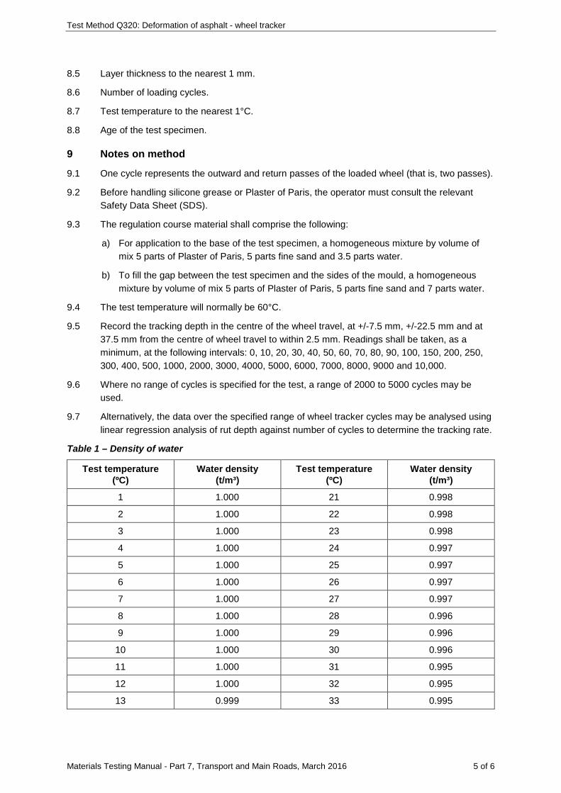
Test Method Q320: Deformation of asphalt - wheel tracker
Materials Testing Manual - Part 7, Transport and Main Roads, March 2016 5 of 6
8.5 Layer thickness to the nearest 1 mm.
8.6 Number of loading cycles.
8.7 Test temperature to the nearest 1°C.
8.8 Age of the test specimen.
9 Notes on method
9.1 One cycle represents the outward and return passes of the loaded wheel (that is, two passes).
9.2 Before handling silicone grease or Plaster of Paris, the operator must consult the relevant Safety Data Sheet (SDS).
9.3 The regulation course material shall comprise the following:
a) For application to the base of the test specimen, a homogeneous mixture by volume of mix 5 parts of Plaster of Paris, 5 parts fine sand and 3.5 parts water.
b) To fill the gap between the test specimen and the sides of the mould, a homogeneous mixture by volume of mix 5 parts of Plaster of Paris, 5 parts fine sand and 7 parts water.
9.4 The test temperature will normally be 60°C.
9.5 Record the tracking depth in the centre of the wheel travel, at +/-7.5 mm, +/-22.5 mm and at 37.5 mm from the centre of wheel travel to within 2.5 mm. Readings shall be taken, as a minimum, at the following intervals: 0, 10, 20, 30, 40, 50, 60, 70, 80, 90, 100, 150, 200, 250, 300, 400, 500, 1000, 2000, 3000, 4000, 5000, 6000, 7000, 8000, 9000 and 10,000.
9.6 Where no range of cycles is specified for the test, a range of 2000 to 5000 cycles may be used.
9.7 Alternatively, the data over the specified range of wheel tracker cycles may be analysed using linear regression analysis of rut depth against number of cycles to determine the tracking rate.
Table 1 – Density of water
Test temperature (ºC)
Water density (t/m³)
Test temperature (ºC)
Water density (t/m³)
1 1.000 21 0.998
2 1.000 22 0.998
3 1.000 23 0.998
4 1.000 24 0.997
5 1.000 25 0.997
6 1.000 26 0.997
7 1.000 27 0.997
8 1.000 28 0.996
9 1.000 29 0.996
10 1.000 30 0.996
11 1.000 31 0.995
12 1.000 32 0.995
13 0.999 33 0.995
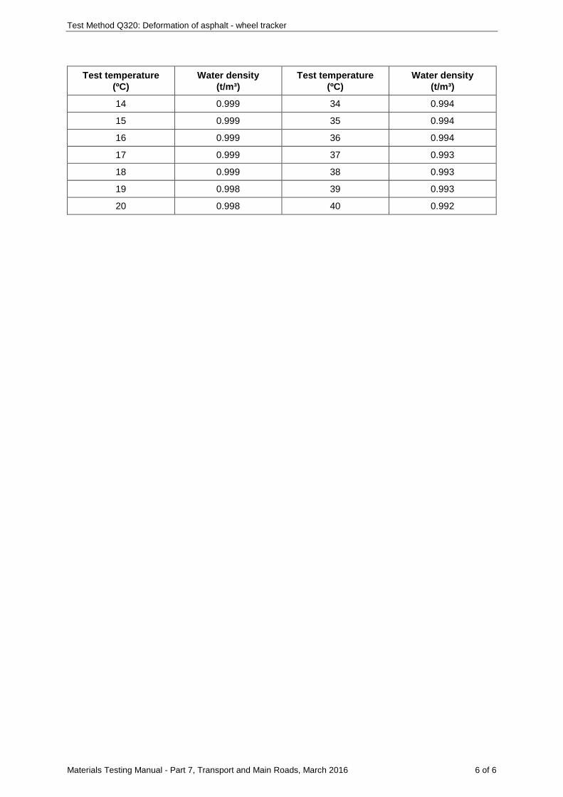
Test Method Q320: Deformation of asphalt - wheel tracker
Materials Testing Manual - Part 7, Transport and Main Roads, March 2016 6 of 6
Test temperature (ºC)
Water density (t/m³)
Test temperature (ºC)
Water density (t/m³)
14 0.999 34 0.994
15 0.999 35 0.994
16 0.999 36 0.994
17 0.999 37 0.993
18 0.999 38 0.993
19 0.998 39 0.993
20 0.998 40 0.992
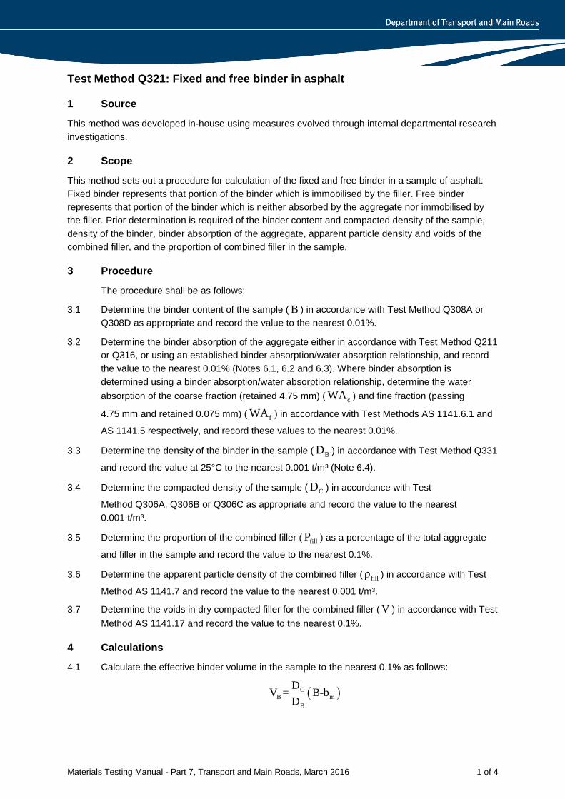
Materials Testing Manual - Part 7, Transport and Main Roads, March 2016 1 of 4
Test Method Q321: Fixed and free binder in asphalt
1 Source
This method was developed in-house using measures evolved through internal departmental research investigations.
2 Scope
This method sets out a procedure for calculation of the fixed and free binder in a sample of asphalt. Fixed binder represents that portion of the binder which is immobilised by the filler. Free binder represents that portion of the binder which is neither absorbed by the aggregate nor immobilised by the filler. Prior determination is required of the binder content and compacted density of the sample, density of the binder, binder absorption of the aggregate, apparent particle density and voids of the combined filler, and the proportion of combined filler in the sample.
3 Procedure
The procedure shall be as follows:
3.1 Determine the binder content of the sample ( B ) in accordance with Test Method Q308A or Q308D as appropriate and record the value to the nearest 0.01%.
3.2 Determine the binder absorption of the aggregate either in accordance with Test Method Q211 or Q316, or using an established binder absorption/water absorption relationship, and record the value to the nearest 0.01% (Notes 6.1, 6.2 and 6.3). Where binder absorption is determined using a binder absorption/water absorption relationship, determine the water absorption of the coarse fraction (retained 4.75 mm) ( cWA ) and fine fraction (passing
4.75 mm and retained 0.075 mm) ( fWA ) in accordance with Test Methods AS 1141.6.1 and
AS 1141.5 respectively, and record these values to the nearest 0.01%.
3.3 Determine the density of the binder in the sample ( BD ) in accordance with Test Method Q331
and record the value at 25°C to the nearest 0.001 t/m³ (Note 6.4).
3.4 Determine the compacted density of the sample ( CD ) in accordance with Test
Method Q306A, Q306B or Q306C as appropriate and record the value to the nearest 0.001 t/m³.
3.5 Determine the proportion of the combined filler ( fillP ) as a percentage of the total aggregate
and filler in the sample and record the value to the nearest 0.1%.
3.6 Determine the apparent particle density of the combined filler ( fillρ ) in accordance with Test
Method AS 1141.7 and record the value to the nearest 0.001 t/m³.
3.7 Determine the voids in dry compacted filler for the combined filler ( V ) in accordance with Test Method AS 1141.17 and record the value to the nearest 0.1%.
4 Calculations
4.1 Calculate the effective binder volume in the sample to the nearest 0.1% as follows:
( )CB m
B
DV = B-bD
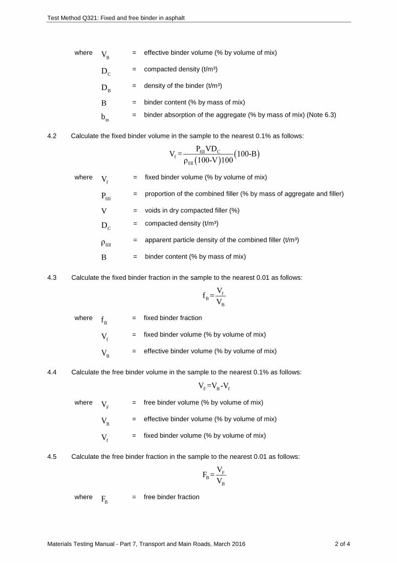
Test Method Q321: Fixed and free binder in asphalt
Materials Testing Manual - Part 7, Transport and Main Roads, March 2016 2 of 4
where BV = effective binder volume (% by volume of mix)
CD = compacted density (t/m³)
BD = density of the binder (t/m³)
B = binder content (% by mass of mix)
mb = binder absorption of the aggregate (% by mass of mix) (Note 6.3)
4.2 Calculate the fixed binder volume in the sample to the nearest 0.1% as follows:
( ) ( )fill Cf
fill
P VDV = 100-Bρ 100-V 100
where fV = fixed binder volume (% by volume of mix)
fillP = proportion of the combined filler (% by mass of aggregate and filler)
V = voids in dry compacted filler (%)
CD = compacted density (t/m³)
fillρ = apparent particle density of the combined filler (t/m³)
B = binder content (% by mass of mix)
4.3 Calculate the fixed binder fraction in the sample to the nearest 0.01 as follows:
fB
B
Vf =V
where Bf = fixed binder fraction
fV = fixed binder volume (% by volume of mix)
BV = effective binder volume (% by volume of mix)
4.4 Calculate the free binder volume in the sample to the nearest 0.1% as follows:
F B fV =V -V
where FV = free binder volume (% by volume of mix)
BV = effective binder volume (% by volume of mix)
fV = fixed binder volume (% by volume of mix)
4.5 Calculate the free binder fraction in the sample to the nearest 0.01 as follows:
FB
B
VF =V
where BF = free binder fraction
Test Method Q321: Fixed and free binder in asphalt
Materials Testing Manual - Part 7, Transport and Main Roads, March 2016 3 of 4
FV = free binder volume (% by volume of mix)
BV = effective binder volume (% by volume of mix)
5 Reporting
Report the following values:
5.1 Effective binder volume to the nearest 0.1%.
5.2 Free binder volume to the nearest 0.1%.
5.3 Fixed binder fraction to the nearest 0.01.
5.4 Fixed binder volume to the nearest 0.1% (where required).
5.5 Free binder fraction to the nearest 0.01 (where required).
6 Notes on method
6.1 Where the binder absorption of the aggregate in the sample is to be obtained using Test Method Q211 but is known from previous determination, further testing in accordance with Q211 is unnecessary.
6.2 Where the binder absorption of the aggregate in the sample is to be obtained using an established binder absorption/water absorption relationship, the following calculation may be used:
ab =0.55WA
where ab = binder absorption of the aggregate (% by mass of aggregate)
WA = water absorption of the aggregate (%)
WA may be calculated using either of the following which assume the filler component to have an absorption value equivalent to the average of the coarse and fine aggregate absorption values.
a) Where water absorption values are available for the coarse and fine fractions of the combined aggregate, calculate the water absorption of the aggregate as detailed in Test Method Q214.
c c f f
c f
P WA +P WAWA=P +P
where WA = water absorption of the aggregate (%)
cP = proportion of coarse aggregate (%)
cWA = water absorption of coarse aggregate (%)
fP = proportion of fine aggregate (%)
fWA =
water absorption of fine aggregate (%)
Test Method Q321: Fixed and free binder in asphalt
Materials Testing Manual - Part 7, Transport and Main Roads, March 2016 4 of 4
b) Where water absorption values are available for the coarse and fine fractions of each individual aggregate component of the combined aggregate, calculate the water absorption as follows:
N
i ii=1
WA= P WA∑
where WA = water absorption of the aggregate (%)
iP = proportion of the ith aggregate component in the combined aggregate
(%)
iWA = water absorption of ith aggregate component calculated using Test
Method Q214(%)
n =
number of aggregate components
6.3 Where binder absorption of the aggregate is determined using Test Method Q211 or an established binder absorption/water absorption relationship, it is expressed as a percentage by mass of aggregate. To convert from percentage by mass of aggregate to percentage by mass of mix, the following calculation may be used:
am a
Bbb =b -100
where mb = binder absorption of the aggregate (% by mass of mix)
ab = binder absorption of the aggregate (% by mass of aggregate)
B = binder content of the sample (%)
6.4 Where the density of the binder is unknown and circumstances do not allow its determination, a value of 1.040 t/m³ may be assumed.
Materials Testing Manual - Part 7, Transport and Main Roads, March 2016 1 of 3
Test Method Q322: Gyratory compaction curve of asphalt
1 Source
This method is based on AS 2891.2.2: Sample preparation - Compaction of asphalt test specimens using a gyratory compactor. It differs from this Australian Standard in that it specifies a set number of compaction cycles and includes some apparatus and procedural variations.
2 Scope
This method sets out the procedure for determining the compaction curve relating specimen height and number of compaction cycles for mixes compacted with a gyratory compactor. It is applicable to asphalt mixes not exceeding 20 mm nominal size.
3 Apparatus
Where appropriate, the working tolerances of particular apparatus are contained in Table 1.
The following apparatus is required:
3.1 Gyratory compactor, capable of applying a vertical loading stress of 240 kPa to a test specimen in a mould at a rate of 60 rpm and at a fixed angle of 2º measured at the centre of the height of the mould. The compactor shall be fitted with the means for providing a continuous readout of test specimen height with the number of compaction cycles.
3.2 Specimen mould assembly, as described in AS 2891.2.2 for 100 mm diameter test specimens.
3.3 Wearing discs, steel discs of diameter 99.8 mm and thickness of 0.9 mm.
3.4 Specimen extractor, of suitable design to enable the test specimen to be removed intact from the mould.
3.5 Oven, thermostatically controlled at a temperature of 150°C.
3.6 Balance of a suitable capacity, having a resolution of at least 0.1 g and with a limit of performance within the range of ± 0.5 g.
3.7 Thermometer, a partial immersion thermometer or other suitable temperature measuring device having a temperature range which includes 150°C, and graduated to 1°C or less with an uncertainty of no more than 0.5°C.
3.8 Assorted mixing and handling apparatus, such as steel trays, trowels, spatulas and scoops.
4 Materials
4.1 Paper discs, having a diameter of about 100 mm.
4.2 Lubricant, suitable light oil for lubricating the paper discs (Note 8.1).
5 Compaction procedure
The procedure shall be as follows:
5.1 Place the specimen mould assembly in the oven for a period of at least 1 hour.
5.2 Remove the mould assembly from the oven and position a lubricated paper disc on the lower wearing disc in the mould.
5.3 Transfer about 1250 g mix into the mould and return the mould assembly to the oven for 60 ± 10 minutes.
Test Method Q322: Gyratory compaction curve of asphalt
Materials Testing Manual - Part 7, Transport and Main Roads, March 2016 2 of 3
5.4 Remove the mould assembly from the oven, place a thermometer in the mix and measure the temperature. Provided that the temperature is within 150 ± 3°C, level the mix in the mould and place a lubricated paper disc on the mix surface (Note 8.2).
5.5 Place the upper wearing disc and top platen on the mix in the mould, position the mould assembly in the gyratory compactor and lock the mould assembly in place.
5.6 Compact the mix in the mould assembly with 350 cycles of gyratory compaction, providing a continuous plot of specimen height against number of cycles.
5.7 Remove the mould assembly from the gyratory compactor and take off the upper platen.
5.8 Allow the mould to cool sufficiently in air and then remove the test specimen from the mould using the specimen extractor, while ensuring the test specimen remains intact and shows no deformation.
5.9 Prepare a further three test specimens using the procedure of Steps 5.1 to 5.8.
5.10 Where the air voids of the mix at 350 cycles is required, determine the following:
5.10.1 The compacted density of each of the test specimens compacted to 350 cycles in accordance with Test Method Q306C.
5.10.2 The maximum density of the mix in accordance with Test Method Q307A.
6 Calculations
Where required, calculate the following:
6.1 The air voids at 350 cycles for each test specimen to the nearest 0.01% in accordance with Test Method Q311 using the compacted density and maximum density values determined in Step 5.10.
6.2 The compacted density at a specified number of cycles for each test specimen to the nearest 0.001 3t/m as follows:
C350 350CN
N
D HD =H
where CND = compacted density of the test specimen at the specified number of
cycles ( 3t/m )
C350D = compacted density of the test specimen at 350 cycles ( 3t/m )
350H = height of the test specimen at 350 cycles (mm)
NH = height of the test specimen at the specified number of cycles (mm)
6.3 The air voids at the specified number of cycles for each test specimen to the nearest 0.01% in accordance with Test Method Q311, using the compacted density determined in Step 6.2 and the maximum density determined in Step 5.10.2.
6.4 The air voids at 350 cycles for the mix to the nearest 0.1% as the average of the air voids results determined in Step 6.1.
6.5 The air voids at the specified number of cycles for the mix to the nearest 0.1% as the average of the air voids results determined in Step 6.3.
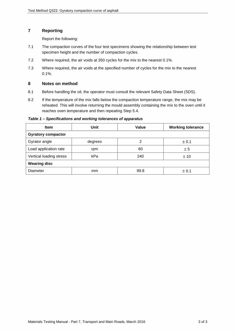
Test Method Q322: Gyratory compaction curve of asphalt
Materials Testing Manual - Part 7, Transport and Main Roads, March 2016 3 of 3
7 Reporting
Report the following:
7.1 The compaction curves of the four test specimens showing the relationship between test specimen height and the number of compaction cycles.
7.2 Where required, the air voids at 350 cycles for the mix to the nearest 0.1%.
7.3 Where required, the air voids at the specified number of cycles for the mix to the nearest 0.1%.
8 Notes on method
8.1 Before handling the oil, the operator must consult the relevant Safety Data Sheet (SDS).
8.2 If the temperature of the mix falls below the compaction temperature range, the mix may be reheated. This will involve returning the mould assembly containing the mix to the oven until it reaches oven temperature and then repeating Step 5.4.
Table 1 – Specifications and working tolerances of apparatus
Item Unit Value Working tolerance
Gyratory compactor
Gyrator angle degrees 2 ± 0.1
Load application rate rpm 60 ± 5
Vertical loading stress kPa 240 ± 10
Wearing disc
Diameter mm 99.8 ± 0.1
Materials Testing Manual - Part 7, Transport and Main Roads, November 2014 1 of 3
Test Method Q323: Equivalent compaction temperature for warm mix asphalt
1 Source
This method is based on the procedure outlined in Warm mix asphalts: tips and tricks developed by professionals for professionals (German Asphalt Paving Association (DAV) 2009). It also makes reference to Australian Standard Test Methods AS/NZS 2891.2.2 and AS/NZS 2891.9.2, and Transport and Main Roads Test Methods Q305, Q306B and Q306C.
2 Scope This method sets out the procedure for determining the equivalent compaction temperature for warm mix asphalt (WMA), by means of comparing and matching the compacted densities of hot mix asphalt (HMA) mix prepared with and without the WMA technology. The method requires prior preparation of sufficient quantities of WMA mix (HMA with the WMA technology) and HMA mix (reference mix). It allows test specimens to be compacted using either gyratory or Marshall compaction.
3 Apparatus
The equipment required for this test method is listed in the following references:
3.1 Q305 Stability, flow and stiffness of asphalt - Marshall
3.2 Q306B Compacted density of dense graded asphalt - presaturation
3.3 Q306C Compacted density of asphalt - silicone sealed
3.4 AS/NZS 2891.2.2 Methods of sampling and testing asphalt - Sample preparation - Compaction of asphalt test specimens using a gyratory compactor
3.5 AS/NZS 2891.9.2 Methods of sampling and testing asphalt - Determination of bulk density of compacted asphalt - Presaturation method
4 Procedure
The procedure shall be as follows:
4.1 Compaction method
Select either the gyratory compaction method (AS/NZS 2891.2.2) or the Marshall compaction method (Q305) as appropriate.
4.2 Specimen preparation
4.2.1 Reference mix specimens
From the sample of HMA mix, compact at least three reference mix specimens in accordance with the relevant method (AS/NZS 2891.2.2 or Q305) at the standard compaction temperature appropriate for the HMA mix design (for example, 150 ± 3°C for mix containing C320 bitumen).
4.2.2 WMA specimens
From the sample of WMA mix, compact at least three WMA specimens at each of several compaction temperatures (for example, 110, 120, 130, 140 and 150 ± 3°C) in accordance with the relevant method (AS/NZS 2891.2.2 or Q305).
Test Method Q323: Equivalent compaction temperature for warm mix asphalt
Materials Testing Manual - Part 7, Transport and Main Roads, November 2014 2 of 3
4.3 Compacted density measurement of specimens
4.3.1 Reference mix specimens:
a) Determine the compacted density to the nearest 0.001 t/m³ of each specimen prepared in Subsection 4.2.1, in accordance with Test Method AS/NZS 2891.9.2, Q306B or Q306C.
b) Calculate the average compacted density for the reference mix specimens to the nearest 0.001 t/m³ and record this as the mix reference density.
4.3.2 WMA specimens
a) Determine the compacted density to the nearest 0.001 t/m³ of each specimen prepared in Subsection 4.2.2, in accordance with Test Method AS/NZS 2891.9.2, Q306B or Q306C.
b) For each set of WMA specimens prepared at each compaction temperature, calculate the average compacted density to the nearest 0.001 t/m³.
4.4 Equivalent compaction temperature for WMA
4.4.1 Plot the average compacted density results of the WMA specimens determined in Subsection 4.3.2(b) against the corresponding compaction temperatures to create a compacted density-temperature curve for WMA, similar to that shown in Figure 1.
4.4.2 Add the average compacted density of reference mix specimens data point determined in Subsection 4.3.1 (b) to the same graph.
4.4.3 As illustrated in Figure 1, determine the temperature corresponding to this reference mix density on the density-temperature curve for WMA. Record this temperature as the calculated equivalent compaction temperature for WMA.
4.5 Validation of calculated equivalent compaction temperature
4.5.1 Compact at least three WMA specimens at the calculated equivalent compaction temperature in accordance with the relevant method (AS/NZS 2891.2.2 or Q305).
4.5.2 Determine the compacted density to the nearest 0.001 t/m³ of each of the validation specimens in accordance with Test Method AS/NZS 2891.9.2, Q306B or Q306C.
4.5.3 Calculate the average compacted density for the validation specimens to the nearest 0.001 t/m³ and record this as the mix validation density.
4.5.4 If the difference between the mix validation density and the mix reference density is ≤ 0.3% of the mix reference density, accept the calculated equivalent compaction temperature as being validated.
4.5.5 If the difference between the mix validation density and the mix reference density is > 0.3% of the mix reference density, repeat the procedure.
5 Reporting
Report the validated equivalent compaction temperature for the WMA to the nearest 5°C.
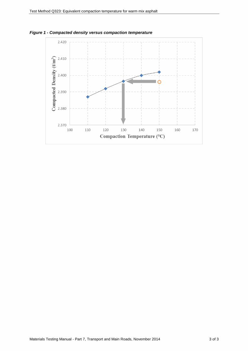
Test Method Q323: Equivalent compaction temperature for warm mix asphalt
Materials Testing Manual - Part 7, Transport and Main Roads, November 2014 3 of 3
Figure 1 - Compacted density versus compaction temperature
Materials Testing Manual - Part 7, Transport and Main Roads, March 2016 1 of 2
Test Method Q324: Rapid drying of compacted asphalt specimens - vacuum
1 Source
This method is based on ASTM D7227: Standard practice for rapid drying of compacted asphalt specimens using vacuum drying apparatus.
2 Scope
This method describes a procedure for drying compacted asphalt specimens using a vacuum drying apparatus. It is applicable to a range of laboratory compacted and field specimens including cylindrical, slab and prism specimens.
3 Apparatus
The following apparatus is required:
3.1 Absorptive cloth for drying the surface of the specimens.
3.2 Vacuum apparatus meeting the following requirements:
3.2.1 Chamber of suitable capacity for asphalt specimens. With a vacuum pump capable of evacuating the chamber and maintaining a pressure of 6 Torr or less. The chamber shall have automatic vacuum, airflow and temperature control features to ensure to ensure drying of the specimens at close to room temperatures (Note 5.1).
3.2.2 Water removable plate, used for removing free water from the bottom of the vacuum chamber.
3.2.3 Electronic cold trap with an airflow divider, used for trapping water before it enters the vacuum pump.
3.3 Balance, a top pan balance of suitable capacity, with a resolution of at least 0.1 g and with a limit of performance within the range of ± 0.5 g.
3.4 Thermometer, an infra-red having a temperature range which includes the range of 15-30 ºC and graduated to 1ºC or less with an uncertainty of no more than 0.5ºC.
4 Procedure
The procedure shall be as follows:
4.1 Checking vacuum apparatus
4.1.1 Follow the manufacturer’s recommendations for warm-up and self-test procedures.
4.1.2 Using an absorptive cloth dry the cold trap and specimen chamber.
4.1.3 Operate the unit without any specimens and check the pressure reading on the display is 6 Torr or less. If the indicated pressure is higher than 6 Torr, check the system for oil level and quality, seals or water in the chamber.
4.2 Drying specimens
4.2.1 Using the infra-red thermometer check the specimen temperature is in the range of 15-30 ºC. If not place the specimens in a room temperature environment until the surface temperature lies within the range of 15-30 ºC.
4.2.2 Using an absorptive cloth remove any excess water from the surface of the specimen.
4.2.3 Determine the wet mass of the specimen ( 1m ).
Test Method Q324: Rapid drying of compacted asphalt specimens - vacuum
Materials Testing Manual - Part 7, Transport and Main Roads, March 2016 2 of 2
4.2.4 Place the specimen on top of a specimen support plate, or on a mesh shelf within the chamber.
4.2.5 Close the vacuum chamber and using the controls start the drying process.
4.2.6 Remove the specimen from the vacuum chamber and determine the dry mass of the specimen ( 2m ).
4.2.7 Return the specimen to the vacuum chamber and dry for at least another 15 minutes.
4.2.8 Repeat Steps 4.2.5 to 4.2.7 until such time that the specimen has reached constant mass (Notes 5.2 and 5.3).
4.2.9 At the completion of the drying process, remove the cold trap lid and the airflow divider plate and wipe out any free standing water in the cold trap.
5 Notes on method
5.1 Since the specimen cools during the evaporation process, making water harder to evaporate at low temperature, it is important to have suitable temperature controls in the chamber to ensure the specimen remains at close to room temperature. Automatic controls within the unit allow the specimen to remain at close to room temperature by periodically allowing a flow of warm air to enter the vacuum chamber. Cycling between vacuum and airflow conditions allows the specimen to dry in a short period of time. Completely saturated specimens can be dried in about 30 minutes. The typical cycling times are 30 to 180 seconds of vacuum operation followed by 30 to 120 seconds of airflow.
5.2 A sample is considered to have reached a constant mass when the difference between successive weighings, after a further 15 minutes vacuum drying, is not more than 0.03 percent.
5.3 Some vacuum apparatus are factory calibrated to sense a "dry specimen condition". For these apparatus Steps 4.2.7 and 4.2.8 may be omitted provided the manufacturers procedure for determining and checking the dry specimen condition is followed.
Materials Testing Manual - Part 7, Transport and Main Roads, March 2016 1 of 7
Test Method Q325: Stability of asphalt – Hamburg wheel tracking device (HWTD)
1 Source
This method applies the principles of AASHTO T324 – Hamburg Wheel-Track Testing of Compacted Hot Mix Asphalt (HMA).
2 Scope
This method describes the procedure for determining the stability of asphalt mixes under loading while submerged in water. It involves monitoring the deformation (rutting) that occurs in an asphalt sample undergoing wheel tracking motion with loaded steel wheels. The method is applicable to asphalt mix either manufactured in the laboratory or sampled from an existing asphalt pavement, and can be performed using asphalt slabs, cores or Laboratory manufactured specimens.
The test is used to determine the susceptibility to failure by means of moisture damage, poor binder properties or structural weakness of the sample in the presence of high temperatures and/or water.
3 Apparatus
The following apparatus is required:
3.1 Wheel Tracker, Hamburg Wheel Tracking Device comprising the following:
3.1.1 Loaded wheel mechanism, consisting of a single or dual steel wheel of diameter 203 mm and width 47 mm. The mechanism shall include a means of loading the wheel so that a force of 705 ± 4.5 N is applied centrally and normal to the top surface of the test specimen.
3.1.2 The wheel shall make 52 ± 2 passes (26 ± 1 cycles) across the specimen per minute, travelling across at least the central 230 mm of the sample.
3.1.3 Test base which should accommodate the fitting of mounting systems up to 400 mm in length and 300 mm in width. There should be (at least) the capabilities to cater for samples from 50 mm to 100 mm in thickness.
3.1.4 Rut depth measurement device, an electronic displacement measuring device, preferably a linear variable displacement transducer (LVDT) having a minimum travel of 20 mm and a limit of performance within the range of ± 0.15 mm.
3.1.5 A means for continuously recording rut depth measurements at progressive numbers of wheel tracker cycles – at least every 100 cycles with more regular readings in the first 100 cycles (e.g. at 1, 2, 3, 4, 5, 6, 7, 8, 9, 10, 20, 30, 40, 50, 60, 70 ,80 ,90, 100, 200, 300 etc. cycles).
3.1.6 Water bath, a water bath able to be controlled to within +/- 1°C of the test temperature. It should be fitted with an overflow device and of sufficient capacity to contain a test specimen with the water level a minimum of 20 mm above it.
3.1.7 A mounting system that allows either moulds containing asphalt slabs, Laboratory prepared specimens or cores to be rigidly fixed to the device.
3.1.8 Core test moulds (Figure 1) consist of the following, metal moulds with internal dimensions of 360 mm by 300 mm. In addition to the metal mould are moulds that consist of a high-density polymer or plastic material that snugly fits into the metal mould does not allow for shifting of the specimen during testing. The mould should be able to accommodate two core or Servopac specimens of 150 mm diameter and thickness of 50 – 100 mm, with the edge of each specimen cut such that the moulds are flush against each other.
Test Method Q325: Stability of asphalt – Hamburg wheel tracking device (HWTD)
Materials Testing Manual - Part 7, Transport and Main Roads, March 2016 2 of 7
3.2 Segmental wheel compactor, capable of applying a loading of 1000 to 30 000 N to within 500 N. The compaction device shall be in the form of a freely rotating wheel segment of diameter 1200 ± 200 mm. The foot of the compaction device shall have an arc length of 400 mm and a width of 300 mm. The compaction foot shall be able to be moved vertically and set to a specified height above the base of the compaction mould. It shall have the option of vibratory compaction and shall be of sufficient rigidity that it will not deform under load over the operating range (Note 9.1).
3.2.1 Compaction table, having an oscillating speed of between 10 and 25 oscillations per minute, and sufficient travel to ensure even compaction of the asphalt in the mould. The table shall have provision to firmly attach the compaction mould.
3.2.2 Compaction moulds, metal moulds of internal dimensions 400 mm length, 300 mm width and of sufficient depth to accommodate the slab specimen mix prior to compaction. To achieve sufficient depth it is allowable to fix a collar to the top of the mould during compaction.
3.3 Lifting device, to move a compaction mould (with or without mix) to and from the compaction table or Wheel Tracking Device.
3.4 Ovens, for heating asphalt and binder, maintained to within ± 3°C of the design mix temperature to allow for attainment of target compaction density.
3.5 Balance of suitable capacity, with a resolution of at least 1 g and with a limit of performance of ± 5 g and capable of below balance weighing for slab specimens.
3.6 Balance of suitable capacity, with a resolution of at least 1 g and with a limit of performance of ± 1 g and capable of below balance weighing for core or Servopac specimens.
3.7 Servopac gyratory compactor, capable of compacting cylindrical pat specimens of 150 mm diameter to a pre-determined thickness and density.
3.8 Saw, diamond tipped masonry saw for cutting samples to size (if required).
3.9 Laboratory tools for specimen preparation, a ruler to measure specimens, a marking medium to identify specimens and a digital camera to document samples before and after testing.
3.10 Straight edge for striking off plaster.
4 Materials
The following materials are required:
4.1 Sealant, acetic cure silicone sealant of known density to the nearest 0.001 t/m³ (Note 9.2).
4.2 Silicone grease (Note 9.2).
4.3 Regulation course material, a mixture of Plaster of Paris and fine sand (Note 9.2).
a) for application to the base of the test specimen, a homogeneous mixture by volume of 5 parts of Plaster of Paris, 5 parts fine sand and 3.5 parts potable water
b) to fill the gap between the test specimen and the sides of the mould, a homogeneous mixture by volume of 5 parts of Plaster of Paris, 5 parts fine sand and 7 parts potable water.
4.4 Potable water.
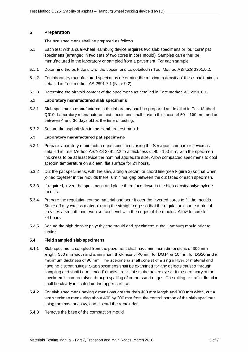
Test Method Q325: Stability of asphalt – Hamburg wheel tracking device (HWTD)
Materials Testing Manual - Part 7, Transport and Main Roads, March 2016 3 of 7
5 Preparation
The test specimens shall be prepared as follows:
5.1 Each test with a dual-wheel Hamburg device requires two slab specimens or four core/ pat specimens (arranged in two sets of two cores in core mould). Samples can either be manufactured in the laboratory or sampled from a pavement. For each sample:
5.1.1 Determine the bulk density of the specimens as detailed in Test Method AS/NZS 2891.9.2.
5.1.2 For laboratory manufactured specimens determine the maximum density of the asphalt mix as detailed in Test method AS 2891.7.1 (Note 9.2)
5.1.3 Determine the air void content of the specimens as detailed in Test method AS 2891.8.1.
5.2 Laboratory manufactured slab specimens
5.2.1 Slab specimens manufactured in the laboratory shall be prepared as detailed in Test Method Q319. Laboratory manufactured test specimens shall have a thickness of 50 – 100 mm and be between 4 and 30 days old at the time of testing.
5.2.2 Secure the asphalt slab in the Hamburg test mould.
5.3 Laboratory manufactured pat specimens
5.3.1 Prepare laboratory manufactured pat specimens using the Servopac compactor device as detailed in Test Method AS/NZS 2891.2.2 to a thickness of 40 - 100 mm, with the specimen thickness to be at least twice the nominal aggregate size. Allow compacted specimens to cool at room temperature on a clean, flat surface for 24 hours.
5.3.2 Cut the pat specimens, with the saw, along a secant or chord line (see Figure 3) so that when joined together in the moulds there is minimal gap between the cut faces of each specimen.
5.3.3 If required, invert the specimens and place them face down in the high density polyethylene moulds.
5.3.4 Prepare the regulation course material and pour it over the inverted cores to fill the moulds. Strike off any excess material using the straight edge so that the regulation course material provides a smooth and even surface level with the edges of the moulds. Allow to cure for 24 hours.
5.3.5 Secure the high density polyethylene mould and specimens in the Hamburg mould prior to testing.
5.4 Field sampled slab specimens
5.4.1 Slab specimens sampled from the pavement shall have minimum dimensions of 300 mm length, 300 mm width and a minimum thickness of 40 mm for DG14 or 50 mm for DG20 and a maximum thickness of 90 mm. The specimens shall consist of a single layer of material and have no discontinuities. Slab specimens shall be examined for any defects caused through sampling and shall be rejected if cracks are visible to the naked eye or if the geometry of the specimen is compromised through spalling of corners and edges. The rolling or traffic direction shall be clearly indicated on the upper surface.
5.4.2 For slab specimens having dimensions greater than 400 mm length and 300 mm width, cut a test specimen measuring about 400 by 300 mm from the central portion of the slab specimen using the masonry saw, and discard the remainder.
5.4.3 Remove the base of the compaction mould.
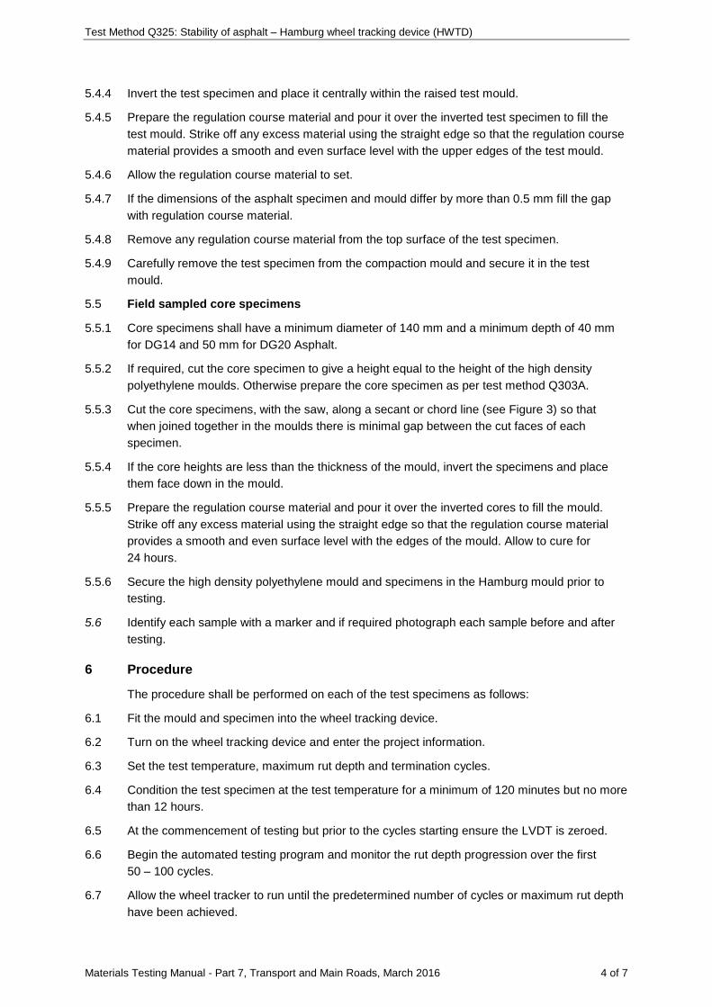
Test Method Q325: Stability of asphalt – Hamburg wheel tracking device (HWTD)
Materials Testing Manual - Part 7, Transport and Main Roads, March 2016 4 of 7
5.4.4 Invert the test specimen and place it centrally within the raised test mould.
5.4.5 Prepare the regulation course material and pour it over the inverted test specimen to fill the test mould. Strike off any excess material using the straight edge so that the regulation course material provides a smooth and even surface level with the upper edges of the test mould.
5.4.6 Allow the regulation course material to set.
5.4.7 If the dimensions of the asphalt specimen and mould differ by more than 0.5 mm fill the gap with regulation course material.
5.4.8 Remove any regulation course material from the top surface of the test specimen.
5.4.9 Carefully remove the test specimen from the compaction mould and secure it in the test mould.
5.5 Field sampled core specimens
5.5.1 Core specimens shall have a minimum diameter of 140 mm and a minimum depth of 40 mm for DG14 and 50 mm for DG20 Asphalt.
5.5.2 If required, cut the core specimen to give a height equal to the height of the high density polyethylene moulds. Otherwise prepare the core specimen as per test method Q303A.
5.5.3 Cut the core specimens, with the saw, along a secant or chord line (see Figure 3) so that when joined together in the moulds there is minimal gap between the cut faces of each specimen.
5.5.4 If the core heights are less than the thickness of the mould, invert the specimens and place them face down in the mould.
5.5.5 Prepare the regulation course material and pour it over the inverted cores to fill the mould. Strike off any excess material using the straight edge so that the regulation course material provides a smooth and even surface level with the edges of the mould. Allow to cure for 24 hours.
5.5.6 Secure the high density polyethylene mould and specimens in the Hamburg mould prior to testing.
5.6 Identify each sample with a marker and if required photograph each sample before and after testing.
6 Procedure
The procedure shall be performed on each of the test specimens as follows:
6.1 Fit the mould and specimen into the wheel tracking device.
6.2 Turn on the wheel tracking device and enter the project information.
6.3 Set the test temperature, maximum rut depth and termination cycles.
6.4 Condition the test specimen at the test temperature for a minimum of 120 minutes but no more than 12 hours.
6.5 At the commencement of testing but prior to the cycles starting ensure the LVDT is zeroed.
6.6 Begin the automated testing program and monitor the rut depth progression over the first 50 – 100 cycles.
6.7 Allow the wheel tracker to run until the predetermined number of cycles or maximum rut depth have been achieved.
Test Method Q325: Stability of asphalt – Hamburg wheel tracking device (HWTD)
Materials Testing Manual - Part 7, Transport and Main Roads, March 2016 5 of 7
6.8 Remove the sample and base frame from the device and remove the specimen from the frame by loosening the bolts.
6.9 Clear the water bath of any loose material and drain if required.
6.10 Take photos of each whole sample after testing. Cut the sample into quarters and take photographs of all internal faces of the specimen.
7 Calculations
7.1 Plot the rut depth vs cycles for each test and identify the creep and stripping sections (if any) of the curve (Figure 2).
7.2 Calculate the following:
7.2.1 Calculate the slope ( cm ) and intercept (Cc)of the creep section of the curve.
7.2.2 Calculate the slope (ms) and intercept of the stripping ( sc ) section of the curve.
7.2.3 Calculate the stripping inflection point as follows:
s c
c s
c - cSIP =m - m
where SIP = stripping inflection point (cycles)
sc = intercept of stripping section of curve (mm)
cc = intercept of creep section of curve (mm)
cm = slope of creep section of curve (mm/cycle)
sm = slope of stripping section of curve (mm/cycle)
8 Reporting
Report the following values and general information:
8.1 Specimen source and form (laboratory or field; slab, pat or core).
8.2 Age of the specimen.
8.3 Number of cycles completed.
8.4 Rut depth (mm) at termination cycles.
8.5 Test temperature.
8.6 Air voids of specimen (%).
8.7 Number of cycles at stripping inflection point.
9 Notes on method
9.1 The Controls Slab Compactor satisfies the requirements of the segmental wheel compactor.
9.2 Before handling the sealant, silicon grease or plaster of paris, the operator must consult the relevant Safety Data Sheet (SDS).
Test Method Q325: Stability of asphalt – Hamburg wheel tracking device (HWTD)
Materials Testing Manual - Part 7, Transport and Main Roads, March 2016 6 of 7
Figure 1 – Core test mould
Figure 2 – Example of rut depth v cycles plot
150
mm
150
mm
Creep Section Stripping Section
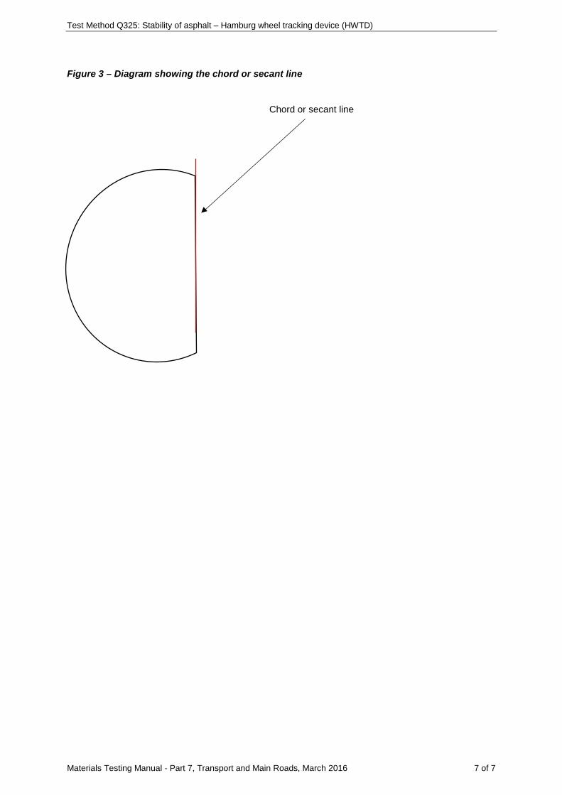
Test Method Q325: Stability of asphalt – Hamburg wheel tracking device (HWTD)
Materials Testing Manual - Part 7, Transport and Main Roads, March 2016 7 of 7
Figure 3 – Diagram showing the chord or secant line
Chord or secant line

![Untitled-1 []Sobha Developers 2.24 Pharmaceuticals 1.46 Dr. Reddy's Laboratories 1.46 Gas 1.15 Indraprastha Gas 1.15 Construction Project 0.97 Larsen & Toubro 0.97 Total Equity 93.80](https://img.pdfslide.us/doc/110x75/603230585b49e508524df68f/untitled-1-sobha-developers-224-pharmaceuticals-146-dr-reddys-laboratories.jpg)


![[XLS]docs.supersalud.gov.co · Web view0.97 0.97499999999999998 0.99 0.96 0.97 0.96799999999999997 0.96899999999999997 0.97 175000 490000 96666 101666 106668 0.95 1 1 1 1 3.9 3 3.3](https://img.pdfslide.us/doc/110x75/5bdcdc9109d3f2fb568ba33f/xlsdocs-web-view097-097499999999999998-099-096-097-096799999999999997.jpg)