Embed Size (px)
Citation preview

Paragon95 Graphical User Interface
© 2003 Kalatel, a GE Interlogix company
All Rights Reserved.
Any GE Interlogix, Kalatel division, software supplied with GE Interlogix, Kalatel division, products is proprietary and furnished under license and can be used or copied only in accordance with the terms of such license.
This equipment has been tested and found to comply with the limits for a Class A digital device, pursuant to part 15 of the FCC Rules. These limits are designed to provide reasonable protection against harmful interference when the equipment is operated in a commercial environment. This equipment generates, uses, and can radiate radio frequency energy and, if not installed and used in accordance with the instruction manual, may cause harmful interference to radio communications.
You are cautioned that any changes or modifications not expressly approved by the party responsible for compliance could void the user's authority to operate the equipment.
This document contains proprietary information that is protected by copyright. No part of this document may be reproduced or transmitted in any form or by any means without the prior written permission of GE Interlogix, Kalatel division.
Paragon product and logo are registered trademarks of GE Interlogix, Kalatel division.
The information contained in this document is subject to change without notice. GE Interlogix, Kalatel division, in keeping pace with technological advances, is a company of product innovation. Therefore, it is difficult to ensure that all information provided is entirely accurate and up-to-date. GE Interlogix, Kalatel division, accepts no responsibility for inaccuracies or omissions and specifically disclaims any liabilities, losses, or risks, personal or otherwise, incurred as a consequence, directly or indirectly, of the use or application of any of the contents of this document.
For the latest product specifications, visit GE Interlogix, Kalatel division, online at www.kalatel.com or contact your GE Interlogix, Kalatel division, sales representative.
For technical support before and after installation, call 800-469-1676. Technical support is available 24 hours a day, 7 days a week.
Call: Tech Support 800-469-1676 (6 A.M. – 5 P.M. PST Monday through Friday) Tech Support 541-740-3589 (all other times) Main 800-343-3358 or 541-754-9133 Fax: Tech Support 541-752-9096 (available 24 hours a day) Main 541-754-7162 Web: www.GE-Interlogix.com
1034449D / March 2003

Paragon95 User Manual Table of Contents
1034449D / March 2003 3
TABLE OF CONTENTS BEFORE YOU BEGIN .......................................................................................................... 6
1 INTRODUCTION ............................................................................................................ 7
1.1 PRODUCT DEFINITION.......................................................................................... 7
1.2 FUNCTIONAL CAPABILITIES................................................................................... 7
1.3 SYSTEM SPECIFICATIONS..................................................................................... 8
1.4 NETWORK DESCRIPTION...................................................................................... 8
2 SETTING UP THE SYSTEM............................................................................................. 9
2.1 PLANNING THE SYSTEM ....................................................................................... 9
2.2 SETTING UP THE COMPUTER................................................................................ 9
2.3 NETWORK STRUCTURE...................................................................................... 10
2.4 CREATING MAPS ............................................................................................... 10
2.5 MAP SIZES ....................................................................................................... 10
2.6 MAP FILES DIRECTORY...................................................................................... 11
2.7 RUNNING PARAGON95 ...................................................................................... 11
2.8 INITIAL SETUP ................................................................................................... 11
2.9 IMPORTING MAP FILES TO PARAGON95 .............................................................. 12
2.10 EDITING MAPS .................................................................................................. 12
2.11 IMPORTING MONITOR MAPS ............................................................................... 12
2.12 PLACING ICONS................................................................................................. 12
2.13 MONITOR SCREEN SETUP.................................................................................. 13
2.14 NAVIGATION ICONS............................................................................................ 13
2.15 P/T/Z SITE SETUP ............................................................................................ 14
2.16 PRESET ICON SETUP ......................................................................................... 15
2.17 SETTING PRESET POSITIONS ............................................................................. 15
2.18 FIXED SITE SETUP ............................................................................................ 16
2.19 AUXILIARY RECEIVER SETUP.............................................................................. 17
2.20 AUXILIARY BUTTON SETUP................................................................................. 18
2.21 ALARMS ........................................................................................................... 19
2.22 ALARM ICONS ................................................................................................... 19
2.23 ALARM RESPONSES .......................................................................................... 20
2.24 FUNCTIONS....................................................................................................... 20

Table of Contents Paragon95 User Manual
4 1034449D / March 2003
2.25 MACRO FUNCTIONS........................................................................................... 21
2.26 MATRIX SWITCHER SETUP ................................................................................. 23
2.27 SCREEN DISPLAY .............................................................................................. 24
2.28 SEQUENCE TOURS ............................................................................................ 24
2.29 TITLES ............................................................................................................. 25
2.30 SEQUENCE DWELL ............................................................................................ 26
2.31 TIME SCHEDULES.............................................................................................. 26
2.32 TIME SCHEDULE: ALARMS.................................................................................. 27
2.33 TIME SCHEDULE: FUNCTIONS/MACROS............................................................... 28
2.34 USER SETUP .................................................................................................... 29
2.35 SYSTEM DOWNLOAD ......................................................................................... 31
2.36 SYSTEM INFO.................................................................................................... 31
2.37 DATA MANAGEMENT.......................................................................................... 32
3 OPERATING THE SYSTEM ........................................................................................... 33
3.1 MAPS............................................................................................................... 33
3.2 EVENTS............................................................................................................ 33
3.3 MONITOR.......................................................................................................... 33
3.4 LOGOUT ........................................................................................................... 34
3.5 CAPTURE ......................................................................................................... 34
3.6 VIEW................................................................................................................ 34
3.7 HELP................................................................................................................ 34
3.8 SIDE CONTROL PANEL....................................................................................... 34
3.9 ICONS .............................................................................................................. 34 3.9.1 Navigation Icons ............................................................................................................35 3.9.2 Fixed Cameras ..............................................................................................................35 3.9.3 Fixed Domes..................................................................................................................35 3.9.4 P/T/Z Cameras ..............................................................................................................35 3.9.5 P/T/Z Domes..................................................................................................................35 3.9.6 Alarms............................................................................................................................35 3.9.7 Access, Misc..................................................................................................................36 3.9.8 Presets...........................................................................................................................36 3.9.9 Status Bar ......................................................................................................................37
4 TROUBLESHOOTING................................................................................................... 38

Paragon95 User Manual Table of Contents
1034449D / March 2003 5
APPENDIX ....................................................................................................................... 39
APPENDIX A: CURRENT ALARM AND ACCESS ACTIONS................................................. 39
APPENDIX B: ALARM PROGRAMMING........................................................................... 40
APPENDIX C: MONITOR ICONS .................................................................................... 41
APPENDIX D: AUXILIARY SITE BEHAVIOR ..................................................................... 41
APPENDIX E: RENUMBERING CAMERAS AND EDITING MACROS ..................................... 41
APPENDIX F: CHANGE IN ALARM TYPE 1 ICON BAR ...................................................... 41
APPENDIX G: MULTIPLEXER MACROS.......................................................................... 41
APPENDIX H: .INI FILES ............................................................................................. 42
APPENDIX I: NUMBER OF ALARMS............................................................................... 43
APPENDIX J: ASSIGNING SITE TIME SCHEDULE FOR MACROS AND DOWNLOADING SITE TITLES................................................................................................... 43
APPENDIX K: TRANSPARENT ALARMS.......................................................................... 43
APPENDIX L: STATUS ALARMS .................................................................................... 44
APPENDIX M: TROUBLE STATE OF ALARMS ................................................................. 44
APPENDIX N: PROGRAMMING CLIENTS FROM A SERVER .............................................. 44
APPENDIX O: PROGRAMMING MACROS WITH REPETITIVE COMMANDS........................... 45
APPENDIX P: MONITOR MAPS..................................................................................... 45
APPENDIX Q: PRESET CAMERA TOURS ....................................................................... 45
APPENDIX R: QUICK SWITCHING CAMERAS AND ALARMS ............................................. 45
APPENDIX S: SETTING UP AREAS FOR CYBERDOME .................................................... 46
PARAGON README FILE .................................................................................................. 47

Before You Begin Paragon95 User Manual
BEFORE YOU BEGIN Read these instructions before installing or operating this product.
Note: This installation should be made by a qualified service person and should conform to local codes.
This manual provides installation and operation information. To use this document, you must have the following minimum qualifications:
A basic knowledge of CCTV systems and components
A basic knowledge of electrical wiring and low-voltage electrical hookups
Intended use
Use this product only for the purpose for which it was designed; refer to the product specification and user documentation.
Customer Support
For assistance in installing, operating, maintaining, and troubleshooting this product, refer to this document and any other documentation provided. If you still have questions, please contact Kalatel Technical Support and Sales:
GE Interlogix, Kalatel division Call: 800-469-1676 Fax: 541-752-9096
Note: You should be at the equipment and ready with details before calling Technical Support.
Conventions Used in this Manual
Boldface or button icons highlight command entries. The following WARNING, CAUTION, and Note statements identify potential hazards that can occur if the equipment is handled improperly:
* WARNING: Improper use of this equipment can cause severe bodily injury or equipment damage.
** CAUTION: Improper use of this equipment can cause equipment damage.
Note: Notes contain important information about a product or procedure.
* This symbol indicates electrical warnings and cautions. ** This symbol indicates general warnings and cautions.
6 1034449D / March 2003

Paragon95 User Manual Introduction
1 INTRODUCTION
1.1 PRODUCT DEFINITION
Paragon95® and Paragon95 NV® (Network Version) are complete hardware and software packages that offer easy programming and control of any size Digiplex® III system.
Maximum System Capacities:
512 Users
64 Monitors
256 Maps
4000 Alarms
512 Cameras
64 Keypads
Note: For Paragon95 NV, the number of users and number of maps applies to each workstation.
1.2 FUNCTIONAL CAPABILITIES
Using point-and-click mouse control, system operators can:
Control pan, tilt, and zoom operations
Capture and print frames of live video
Find preset points and set preset tours
Switch any camera to any monitor
Display live video on the computer monitor
Control cameras using MouseTrak control
Execute more than 150 preprogrammed functions and macro functions
Set multiple time schedules for alarms and functions
Control access to a remote gate, turnstile, or door
Sequence among selected cameras
Archive responses to any events that occur
Communicate with 10 workstations over a network
Perform many additional tasks
1034449D / March 2003 7
Introduction Paragon95 User Manual
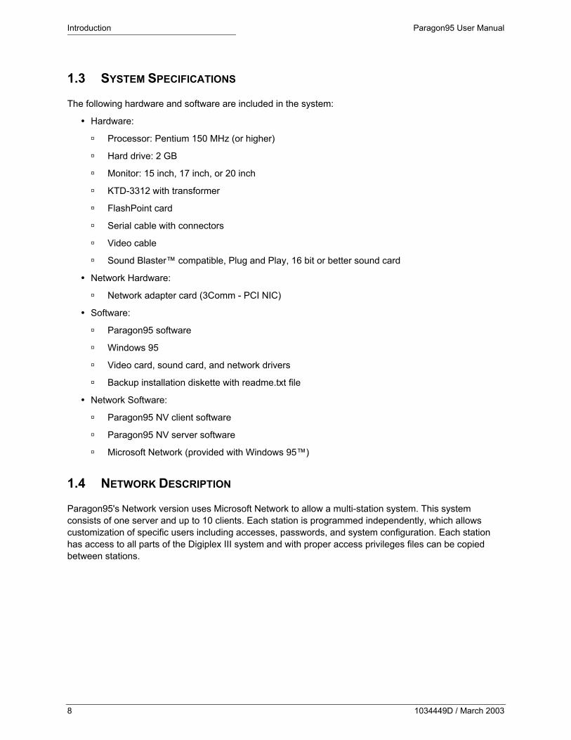
1.3 SYSTEM SPECIFICATIONS
The following hardware and software are included in the system:
Hardware:
Processor: Pentium 150 MHz (or higher)
Hard drive: 2 GB
Monitor: 15 inch, 17 inch, or 20 inch
KTD-3312 with transformer
FlashPoint card
Serial cable with connectors
Video cable
Sound Blaster™ compatible, Plug and Play, 16 bit or better sound card
Network Hardware:
Network adapter card (3Comm - PCI NIC)
Software:
Paragon95 software
Windows 95
Video card, sound card, and network drivers
Backup installation diskette with readme.txt file
Network Software:
Paragon95 NV client software
Paragon95 NV server software
Microsoft Network (provided with Windows 95™)
1.4 NETWORK DESCRIPTION
Paragon95's Network version uses Microsoft Network to allow a multi-station system. This system consists of one server and up to 10 clients. Each station is programmed independently, which allows customization of specific users including accesses, passwords, and system configuration. Each station has access to all parts of the Digiplex III system and with proper access privileges files can be copied between stations.
8 1034449D / March 2003

Paragon95 User Manual Setting Up the System
2 SETTING UP THE SYSTEM
2.1 PLANNING THE SYSTEM
To plan your system determine the following:
Number of users
Privileges to be assigned to each user
Password for each user
Number and layout of site maps
Number of alarms
Number and types of cameras
Number and types of auxiliaries
Number of monitors
Network parameters
2.2 SETTING UP THE COMPUTER
Make cable connections as shown in Figure 1.
Monitor power
PC power
Keyboard (five-pin DIN)
Mouse (DB 9 P)
KTD-3312 serial port (DB25 P)
Printer parallel port (DB25 S)
Video card
Monitor (15-pin VGA)
Video (DB 25 S)
Network card
Sound card
MIDI/game Microphone
Speaker Line in
Line out
Figure 1. Making cable connections
1034449D / March 2003 9

Setting Up the System Paragon95 User Manual
2.3 NETWORK STRUCTURE
RS422 control signal in Clients 1 – 10
KTD-3312 Network hub
RS422 control signal out Twisted-pair Ethernet
Server
Figure 2. Typical network structure
2.4 CREATING MAPS
Paragon95 accepts graphics in many file formats, including construction drawings and aerial photographs. Maps are used for the majority of the functions in this system, which makes their design critical. Before creating the maps, the installer should carefully plan the manner in which they will link together. This will help determine how much detail must be included in each map. You should develop an overview map of the entire facility, which will act as a master from which close-ups of specific areas can be viewed.
See Table 1 for a partial list of the formats that can be used for mapping in Paragon95.
Table 1. Partial list of acceptable image formats
.bmp .cal .eps .img .gif .cut .ico .tga
.iff .ica .jpg .dcx .lv .mac .msp .pcx
.psd .pcd .pct .xpm .ras .tif .wmf .wpg
.xbm
2.5 MAP SIZES
Paragon95 reserves a large portion of the screen for site maps. The best map size varies, depending on the screen resolution. For a screen at 800 x 600 resolution, each map should be 629 pixels horizontal by 503 pixels vertical.
10 1034449D / March 2003

Paragon95 User Manual Setting Up the System
Note: Any size of map is acceptable, but smaller maps will not fill the reserved space and larger maps will require scrolling.
2.6 MAP FILES DIRECTORY Note: System map files must be saved to the C:\Parago32\graphics directory to be accessible to Paragon95 system.
2.7 RUNNING PARAGON95 1) Turn on the system. The Paragon95 access screen appears.
2) Enter user name and password.
Note: A factory default user name and password "Kalatel" provides full access to all portions of the program. Refer to Section 2.34, User Setup, to customize access.
2.8 INITIAL SETUP
To enter system information, perform the following.
Figure 3. Initial Setup dialog
1) Select System Setup - Initial Setup from the Program menu. The Initial Setup dialog (Figure 3) appears.
2) Enter the following information about the Digiplex III system:
Number of sites
Number of monitors
Number of keypads
Number of alarms
Serial Port Port to which the 3312 interface is connected
Timeout Time duration when no activity occurs before Paragon95 logs out the current user
Password Timeout Time given to enter a password
Baud Rate Output transmission rate to the KTD-3312
Video Format 50 cycle or 60 cycle power
Time Source Computer-generated source or KTS-53-1
1034449D / March 2003 11

Setting Up the System Paragon95 User Manual
2.9 IMPORTING MAP FILES TO PARAGON95
Figure 4. Add New Map dialog
To import a map file see Figure 4 and perform the following.
1) Select Site Maps - New Map from the Program menu. The Add New Map dialog appears.
2) Click Import File.
3) Select a map file from the directory.
4) Enter a description to identify the map in the Maps menu.
Note: The map file must be saved to the C:\Parago32\graphics directory.
2.10 EDITING MAPS
Figure 5. Edit Map Properties dialog
To edit a map, see Figure 5 and perform the following.
1) Select Site Maps - Edit Map from the Program menu. The Edit Map Properties dialog appears.
2) Change map descriptions, import new maps, or change a maps overview status.
Note: Only one map can have overview status.
2.11 IMPORTING MONITOR MAPS
Figure 6. Edit Monitor Plan dialog
To import a monitor map see Figure 6 and perform the following.
1) Select Monitor Plan from the Program menu. The Edit Monitor Plan dialog appears.
2) Click Import File to import an image file to use as a background for placing monitors. The image should represent your actual monitor console for easy reference.
Note: The map file must be saved to the C:\Parago32\graphics directory.
2.12 PLACING ICONS
To place icons, click and drag icons from those displayed at the bottom of the screen. Alternatively, perform the following.
1) Select Program in the top button bar.
2) Select the appropriate category from the pop-up box in the bottom left corner of the screen.
3) Click and drag the icon to the desired location. A system parameters assignment dialog appears.
12 1034449D / March 2003

Paragon95 User Manual Setting Up the System
2.13 MONITOR SCREEN SETUP
To set up the monitor screen, see Figure 7 and Figure 8 and perform the following.
1) Click Monitor. The monitor screen appears.
2) Click Program to enter programming mode. An icon bar appears at the bottom of the screen.
Note: The icon bar includes several monochrome monitors and one with a blue screen. The blue monitor represents your computer and must have its corresponding switcher output. The rest represent monitors in your console.
3) To place an icon, click and drag it to the desired location.
4) The Edit Monitor dialog appears. Select the monitor’s corresponding switcher number.
Figure 7. Edit Monitor dialog Figure 8. Monitor Icons
2.14 NAVIGATION ICONS
The Map-Linking Setup dialog (Figure 9) appears any time a Map icon (Figure 10) is placed. Use these icons to switch among site maps.
Figure 9. Map-Linking Setup dialog Figure 10. Map icons
1034449D / March 2003 13

Setting Up the System Paragon95 User Manual
2.15 P/T/Z SITE SETUP
The P/T/Z Site Setup dialog (Figure 11) appears any time a P/T/Z Dome or P/T/Z Camera icon (Figure 12) is placed.
Figure 11. P/T/Z Site Setup dialog
Figure 12. PT//Z site setup icons
14 1034449D / March 2003

Paragon95 User Manual Setting Up the System
2.16 PRESET ICON SETUP
The Preset Icon Setup dialog (Figure 13) appears any time a Preset icon (Figure 14) is placed. Use this dialog to set a preset point for an assigned P/T/Z camera.
Figure 13. Preset Icon Setup dialog
Figure 14. Preset icons
2.17 SETTING PRESET POSITIONS
Figure 15. Select Preset menu
To define preset camera positions for the selected site, click Preset on the P/T/Z Site Setup dialog (Figure 11). The Select Preset dialog (Figure 15) appears.
To program a preset tour, click Tour after a preset is defined. Right-click to select among tours 1 through 4 on CyberDome® programming.
To facilitate preset position programming, video is directed from the selected sites camera to the on-screen video (if available).
1034449D / March 2003 15

Setting Up the System Paragon95 User Manual
2.18 FIXED SITE SETUP The Fixed Site Setup dialog (Figure 16) appears when a Fixed Camera or Fixed Dome icon (Figure 17) is placed.
Figure 16. Fixed Site Setup dialog
Figure 17. Fixed site icons
16 1034449D / March 2003
Paragon95 User Manual Setting Up the System
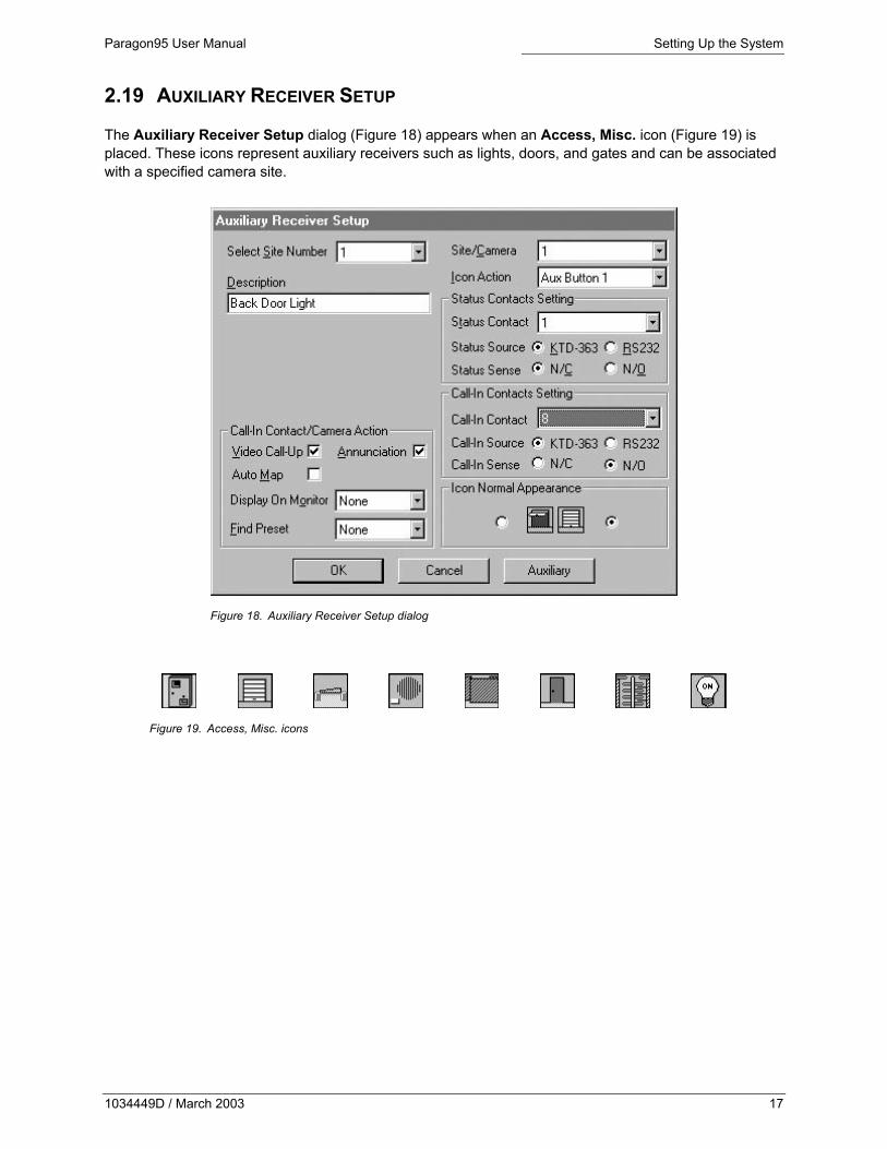
2.19 AUXILIARY RECEIVER SETUP
The Auxiliary Receiver Setup dialog (Figure 18) appears when an Access, Misc. icon (Figure 19) is placed. These icons represent auxiliary receivers such as lights, doors, and gates and can be associated with a specified camera site.
Figure 18. Auxiliary Receiver Setup dialog
Figure 19. Access, Misc. icons
1034449D / March 2003 17

Setting Up the System Paragon95 User Manual
2.20 AUXILIARY BUTTON SETUP
To display the Auxiliary Button Setup dialog (Figure 20), click Auxil from either the P/T/Z Site Setup dialog (Figure 11) or the Auxiliary Receiver Setup dialog (Figure 18).
Figure 20. Auxiliary Button Setup dialog
Program one function or macro function for each of the eight Aux buttons. Program the Aux buttons individually for each P/T/Z and auxiliary receiver site.
18 1034449D / March 2003

Paragon95 User Manual Setting Up the System
2.21 ALARMS
The Alarm Contact Setup dialog (Figure 21) appears any time an Alarm icon (Figure 22, Figure 23, and Figure 24) is placed.
Figure 21. Alarm Contact Setup dialog
Use this dialog to define the parameters of the alarm point and to select and program any alarm contact or group of alarms in the system.
2.22 ALARM ICONS
Paragon95 supports three types of Alarm icons. Each type performs different actions when the alarm is activated.
Type I icons execute all programmed events immediately when the contact is tripped. (See Figure 22)
Figure 22. Type I alarm icons
1034449D / March 2003 19

Setting Up the System Paragon95 User Manual
Type II icons flash and beep to alert the guard when a contact is tripped. The programmed actions are not executed until the guard acknowledges the alarm. (See Figure 23)
Figure 23. Type II alarm icons
Type III icons make it possible for two programmed macros to be executed by a single alarm contact. The first is executed when the contact is tripped, and the second is executed when the guard acknowledges the alarm. (See Figure 24)
Figure 24. Type III alarm icons
2.23 ALARM RESPONSES
Use the Predefined Alarm Responses dialog (Figure 25) to administer up to 32 predefined alarm responses for a given alarm event.
Figure 25. Predefined Alarm Responses dialog
2.24 FUNCTIONS
To enter descriptions for preprogrammed functions, see Figure 26 perform the following.
1) Select Functions from the Program menu. The Functions dialog appears.
2) Select the desired function from the Select Function drop down.
20 1034449D / March 2003
Paragon95 User Manual Setting Up the System
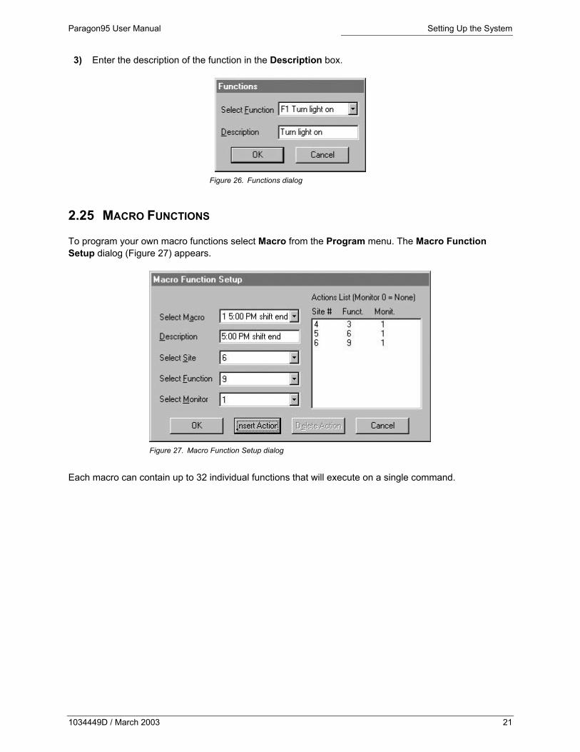
3) Enter the description of the function in the Description box.
Figure 26. Functions dialog
2.25 MACRO FUNCTIONS
To program your own macro functions select Macro from the Program menu. The Macro Function Setup dialog (Figure 27) appears.
Figure 27. Macro Function Setup dialog
Each macro can contain up to 32 individual functions that will execute on a single command.
1034449D / March 2003 21
Setting Up the System Paragon95 User Manual
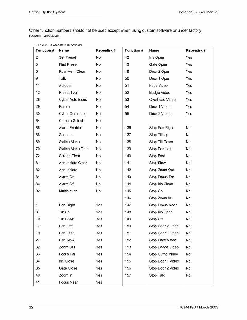
Other function numbers should not be used except when using custom software or under factory recommendation.
Table 2. Available functions list
Function # Name Repeating? Function # Name Repeating?
2 Set Preset No 42 Iris Open Yes
3 Find Preset No 43 Gate Open Yes
5 Rcvr Mem Clear No 49 Door 2 Open Yes
9 Talk No 50 Door 1 Open Yes
11 Autopan No 51 Face Video Yes
12 Preset Tour No 52 Badge Video Yes
28 Cyber Auto focus No 53 Overhead Video Yes
29 Param No 54 Door 1 Video Yes
30 Cyber Command No 55 Door 2 Video Yes
64 Camera Select No
65 Alarm Enable No 136 Stop Pan Right No
66 Sequence No 137 Stop Tilt Up No
69 Switch Menu No 138 Stop Tilt Down No
70 Switch Menu Data No 139 Stop Pan Left No
72 Screen Clear No 140 Stop Fast No
81 Annunciate Clear No 141 Stop Slow No
82 Annunciate No 142 Stop Zoom Out No
84 Alarm On No 143 Stop Focus Far No
86 Alarm Off No 144 Stop Iris Close No
92 Multiplexer No 145 Stop On No
146 Stop Zoom In No
1 Pan Right Yes 147 Stop Focus Near No
8 Tilt Up Yes 148 Stop Iris Open No
10 Tilt Down Yes 149 Stop Off No
17 Pan Left Yes 150 Stop Door 2 Open No
19 Pan Fast Yes 151 Stop Door 1 Open No
27 Pan Slow Yes 152 Stop Face Video No
32 Zoom Out Yes 153 Stop Badge Video No
33 Focus Far Yes 154 Stop Ovrhd Video No
34 Iris Close Yes 155 Stop Door 1 Video No
35 Gate Close Yes 156 Stop Door 2 Video No
40 Zoom In Yes 157 Stop Talk No
41 Focus Near Yes
22 1034449D / March 2003

Paragon95 User Manual Setting Up the System
Table 3. Available multiplexer function commands
Site # Operation Site # Operation Site # Operation
1 Input 1 10 Input 10 19 Seq
2 Input 2 11 Input 11 20 Tape
3 Input 3 12 Input 12 21 Zoom
4 Input 4 13 Input 13 22 Pip
5 Input 5 14 Input 14 23 2X2
6 Input 6 15 Input 15 24 3X3
7 Input 7 16 Input 16 25 4X4
8 Input 8 17 Live
9 Input 9 18 Alt/Ctrl
To execute a multiplexer function with a macro perform the following.
1) Select the site number for the desired operation from Table 3 and enter it.
2) Enter the multiplexer function number 92 (Table 2).
3) Enter the monitor number that corresponds to the multiplexer receiver site address (KTD-93).
Example: To display the 2X2 view on the multiplexer number 03, enter the following information in the macro:
Site Number-23 Function Number-92 Monitor Number-03
2.26 MATRIX SWITCHER SETUP
To program the matrix switchers, perform the following.
1) Select System Setup-Switcher Setup from the Program menu. The select monitors dialog appears (Figure 28).
2) Select or deselect monitors to be programmed.
Note: Active monitors will appear to be pushed in and their numbers will turn red.
1034449D / March 2003 23

Setting Up the System Paragon95 User Manual
Figure 28. Select monitors dialog
2.27 SCREEN DISPLAY
To program on-screen display positions for selected monitors, click OK on the select monitors dialog (Figure 28). The Matrix Switcher Setup dialog (Figure 29) appears.
Figure 29. Matrix Switcher Setup – Screen Display dialog
2.28 SEQUENCE TOURS
To program Sequence Tours for the selected monitor(s) perform the following.
3) Click OK on the Select Monitors dialog (Figure 28). The Sequence Tours dialog appears.
4) Click Seq. Tours. The Matrix Switcher Setup – Seq. Tours dialog (Figure 30) appears.
24 1034449D / March 2003
Paragon95 User Manual Setting Up the System
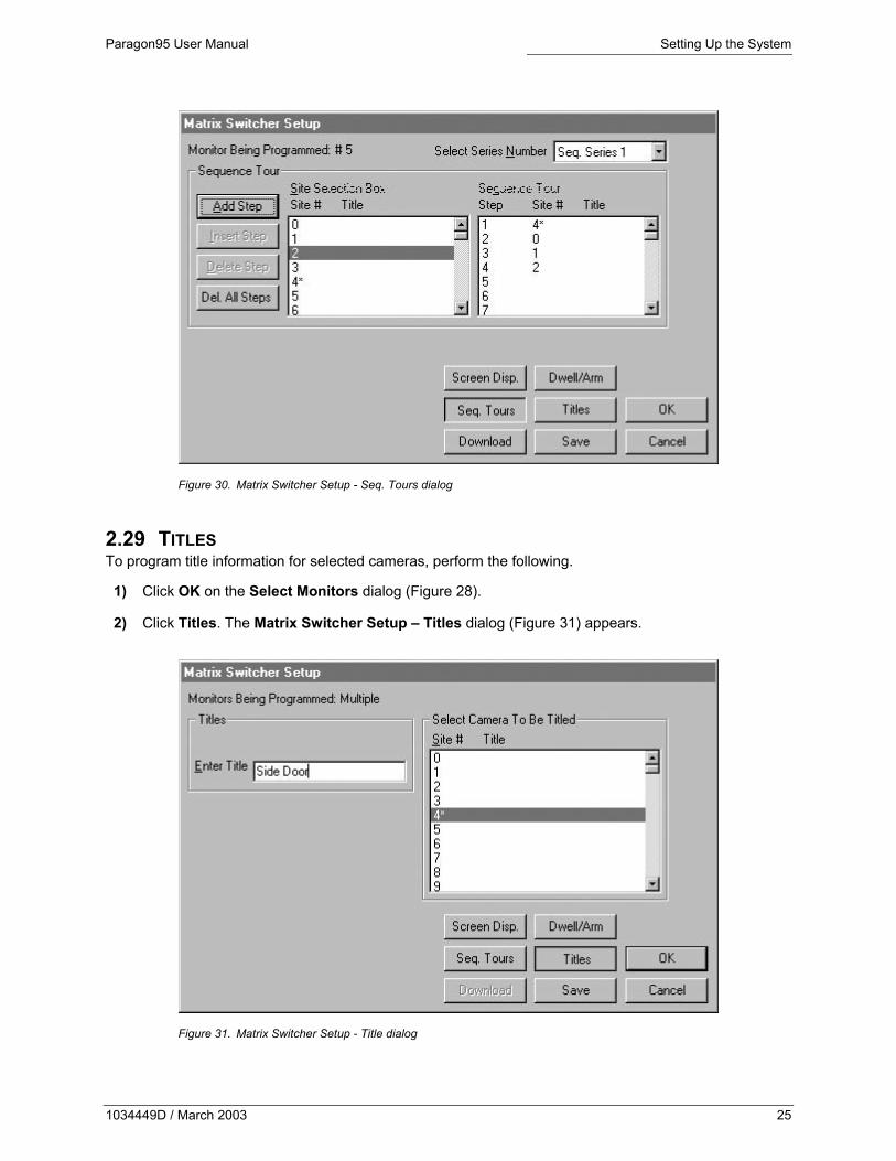
Figure 30. Matrix Switcher Setup - Seq. Tours dialog
2.29 TITLES To program title information for selected cameras, perform the following.
1) Click OK on the Select Monitors dialog (Figure 28).
2) Click Titles. The Matrix Switcher Setup – Titles dialog (Figure 31) appears.
Figure 31. Matrix Switcher Setup - Title dialog
1034449D / March 2003 25

Setting Up the System Paragon95 User Manual
2.30 SEQUENCE DWELL
To program dwell time and alarm arming settings for selected monitors perform the following.
1) Click OK on the Select Monitors dialog.
2) Click Dwell/Arm. The Matrix Switcher Setup – Sequence Dwell dialog (Figure 32) appears.
Figure 32. Matrix Switcher Setup - Dwell/Arm dialog
2.31 TIME SCHEDULES Note: Paragon95 uses either a KTD-53-1 (time/date generator) or the computer's internal clock to keep time.
To schedule events to occur at specific times during the day or at specific intervals of time, perform the following.
1) Select System Setup-Time Schedule from the Program menu. The Time Schedule dialog (Figure 33) appears.
2) Program desired events such as arming and disarming alarms, starting or stopping receiver functions/macro functions, and granting or denying keypad access.
26 1034449D / March 2003

Paragon95 User Manual Setting Up the System
Figure 33. Time Schedule dialog
2.32 TIME SCHEDULE: ALARMS 1) In the Select area, click Alarms. The Time Schedule – Alarms dialog (Figure 34) appears.
2) Select a group from the Alarm Select Box list. The selected alarms display in the Group list.
Figure 34. Time Schedule – Alarms dialog
3) Click Set Time. The Time Schedule – Alarms, Time Select dialog (Figure 35) appears.
4) Schedule up to six events to occur at specified times during each day. You can also schedule events to occur on all days, weekdays, weekends, and holidays.
1034449D / March 2003 27
Setting Up the System Paragon95 User Manual
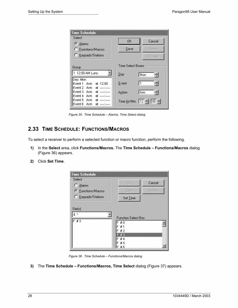
Figure 35. Time Schedule – Alarms, Time Select dialog
2.33 TIME SCHEDULE: FUNCTIONS/MACROS
To select a receiver to perform a selected function or macro function, perform the following.
1) In the Select area, click Functions/Macros. The Time Schedule – Functions/Macros dialog (Figure 36) appears.
2) Click Set Time.
Figure 36. Time Schedule – Functions/Macros dialog
3) The Time Schedule – Functions/Macros, Time Select dialog (Figure 37) appears.
28 1034449D / March 2003

Paragon95 User Manual Setting Up the System
4) Set the day, event, and time for the selected function or macro function to be executed. Six scheduled events can occur each day, weekdays, holidays, weekends, or all days.
Figure 37. Time Schedule – Functions/Macros, Time Select dialog
2.34 USER SETUP Note: When first entering Paragon95, enter the factory default user name and password. Assign yourself full privileges, return to the main operating screen and log out. Now log in with your newly assigned user name and password and delete the factory default ones.
Note: Deleted factory default passwords cannot be retrieved.
To control user access to the Paragon95 system perform the following.
1) Select Administration - Users from the Program menu. The Select Users dialog (Figure 38) appears.
Figure 38. Select Users dialog
2) To copy the privileges of an existing user to other users click Copy Priv.
1034449D / March 2003 29

Setting Up the System Paragon95 User Manual
3) To enter a new user click New User. The New User dialog (Figure 39) appears.
Figure 39. New User dialog
4) Enter the new user name, password, and privileges.
5) Click OK.
6) To make changes to the name, password, and privileges of a user, highlight the name from the Select Users dialog and click Edit User. The Edit User dialog (Figure 40) appears.
Figure 40. Edit User dialog
30 1034449D / March 2003

Paragon95 User Manual Setting Up the System
7) To edit a user's security privileges, highlight the name from the Select Users dialog and click Privileges. The User’s Security Privileges dialog (Figure 41) appears.
Figure 41. User’s Security Privileges dialog
8) To permit or deny access to stations, maps, sites, and monitors, highlight any of these items and click on Permit Access or Deny Access accordingly; or click Program Bttn to automatically grant access to everything except stations.
2.35 SYSTEM DOWNLOAD
Click Program - System Download to download system programming to Digiplex components other than Paragon95.
Camera Titles downloads only camera titles to the Kalatel switcher (KTD-348, or KTD-341) in your system.
Switchers Only downloads only switcher information (sequence tours, titles, text positioning, etc.).
Receivers Only downloads only receiver programming to CyberDomes, KTA-12 domes, and receiver drivers.
All downloads all programmed information not stored in Paragon95.
2.36 SYSTEM INFO
Click View - System Info to view all of Paragon's programmed system information in a spreadsheet format. To print any of these spreadsheets click View - Print.
1034449D / March 2003 31

Setting Up the System Paragon95 User Manual
Alarms displays information on all alarm contact #'s, camera assignment, map location, alarm type, and all other programmed information.
Alarm Time Schedule displays information on the affected day(s), and the associated events.
P/T/Z Receivers displays information on the camera #, camera description, camera type, and programming parameters.
Sites displays information on site icons, their assigned #, title, site map, and icon type (access, preset target, monitor, etc.).
Site Time Schedule displays information for the affected day(s), and the assigned events.
Users displays information on the user name, user status, map access, site access, monitor access, shunt level, and acknowledge level.
2.37 DATA MANAGEMENT
Click Program - Data Management to display the following files-saving options.
Save All saves all information programmed into the Paragon95 system.
Save User File (*.1st.) As saves user information including all defined users and their access privileges.
Save Icons (*.2nd) As saves all icon placements within your system.
Save Non-Icons (*.3rd) As saves all programmed information not included in the previous two options, including monitor sequences, time scheduling, macro-function and function setup.
32 1034449D / March 2003

Paragon95 User Manual Operating the System
3 OPERATING THE SYSTEM Paragon95 allows operation of the entire system from the mouse. The program contains a fixed top button bar and side control panel from which you navigate the system. The remainder of the screen is reserved for site maps, which contain icons representing your system elements.
3.1 MAPS
Click Maps to display the Maps menu. To display a map select it from the list of system maps. To display an overview or previous maps click their respective buttons.
3.2 EVENTS
To view events click Events in the top button bar. The Events dialog (Figure 42) appears.
Figure 42. Events dialog
The Events dialog displays events that occurred during your log-in period. These are categorized in Access, Capture, Memo, Alarms, or All categories. You can also View, Print, and Delete video captures, or enter a memo related to any listed event.
3.3 MONITOR
Click Monitor to display your monitor console. Click on a Monitor icon to select a camera site to display on that monitor, select a preprogrammed sequence, or determine whether alarms display on that monitor. The monitor screen will also display one blue-screened icon, which represents your computers on-screen video image.
1034449D / March 2003 33

Operating the System Paragon95 User Manual
Figure 43. Monitor icons
3.4 LOGOUT
Clicking Logout displays two options for leaving the system: Close Station and Log-Out. Selecting Close Station exits the operating screen completely, and selecting Log-Out denies privileges until you log back in.
3.5 CAPTURE
Clicking Capture captures a frame of video that can be viewed, printed, or deleted from the Events dialog (Figure 42).
3.6 VIEW
Click View to access a menu that includes the following options:
Brightness controls the brightness of your on-screen video
Clear All Alarms clears all currently active alarms
Full Screen, 1/3 Screen, and Video Off control the size and status of the video window
Video Hold maintains on-screen video while selecting alternate auxiliary sites
Toggle System Info enables you to view or print current system information regarding Alarms, Sites, P/T/Z Sites, and Time Schedules.
3.7 HELP
Detailed help can be accessed from anywhere in the system by clicking Help.
3.8 SIDE CONTROL PANEL
The side control panel consists of three parts: the mouse image, which details what buttons control what camera functions; the Video, Auto, and Tour buttons, which toggle on-screen video, start auto panning, and start preset tours respectively; and eight Aux buttons, which execute auxiliary functions programmed for the selected access or camera site.
3.9 ICONS Paragon95 has eight different categories of icons to represent system elements:
34 1034449D / March 2003

Paragon95 User Manual Operating the System
3.9.1 NAVIGATION ICONS
Navigation icons (Figure 44) are linked with another map in the system. Click one to automatically switch to its corresponding map.
Figure 44. Navigation icons
3.9.2 FIXED CAMERAS
Fixed Camera icons (Figure 45) represent a fixed camera in the system. Click one to display video from the corresponding camera.
Figure 45. Fixed camera icons
3.9.3 FIXED DOMES
Figure 46. Fixed Dome icon
Fixed Dome icons represent a fixed dome in the system. Click one to display video from the corresponding camera.
3.9.4 P/T/Z CAMERAS
Figure 47. P/T/Z camera
icons
P/T/Z Camera icons represents a P/T/Z camera in this system. Click one to automatically call video from its corresponding camera.
3.9.5 P/T/Z DOMES
Figure 48. P/T/Z Dome icons
P/T/Z Dome icons represent a P/T/Z dome in this system. Click one to automatically call video from its corresponding camera.
3.9.6 ALARMS
Each Alarm icon represents a specific alarm in the system. When an alarm is active, its icon flashes and beeps until acknowledged.
Figure 49. Alarm icons
1034449D / March 2003 35

Operating the System Paragon95 User Manual
To acknowledge an active alarm, click on its icon and respond to the *Alarm* dialog (Figure 50) that appears.
Figure 50. *ALARM* dialog
Use the *Alarm* dialog to acknowledge or shunt an alarm or enter a memo in response to the selected alarm.
The Pending button on the top menu bar will flash when there are active alarms. If this is clicked, the Active Alarms & Call In Requests dialog appears. This lists all active alarms; if you select one and click OK, the screen will switch to that alarm and its corresponding map.
3.9.7 ACCESS, MISC.
The Access, Misc. icons (Figure 51) each represent an accessory receiver in the system. These accessories include lights, doors, and gates and some have programmed Aux buttons associated with them. Click an Access, Misc. icon and an Aux button on the side control panel will change to read what functions can be executed at this particular site.
Figure 51. Access, Misc. icons
3.9.8 PRESETS
Figure 52. Preset icons
Each Preset icon (Figure 52) represents a preset position for a selected camera in the system. Click one to display video from the associated camera.
36 1034449D / March 2003

Paragon95 User Manual Operating the System
3.9.9 STATUS BAR
The status bar is located along the bottom of the screen and displays information regarding any icon that is moused-over. It also displays the current user name, time, and date.
1034449D / March 2003 37

Troubleshooting Paragon95 User Manual
38 1034449D / March 2003
4 TROUBLESHOOTING
Error Message/Problem Solution(s)
SERIAL LINK BREACH 1) Check serial cable connections to computer and KTD-3312.
2) Does the KTD-3312 have power (red LED light should be on).
3) Is the RS422 cable connected to KTD-3312 (red and black wire).
4) Check the KTD-3312 software version. To do this, select About Paragon95 from the Program menu. The version noted on the bottom of this dialog must be equal to or higher than the version listed directly above it.
The Device is Already Open (Possibly Used by Other Application) When Opening (Com#)
If this occurs during boot up, reboot the computer.
SERIAL PORT NOT INITIALIZED
Select Reinitialize Serial Port from the View menu.
No live video appears in the video window
Test to see if video cable is loose.
Cameras are not switching 1) Is the blue monitor placed on the monitor map?
2) Is the blue monitor numbered accordingly to the proper switcher card? The on-screen video must have its own dedicated switcher card and this blue monitor must contain that monitor card's number.

Paragon95 User Manual Appendix
APPENDIX
APPENDIX A: CURRENT ALARM AND ACCESS ACTIONS 1) Type 1, On/Action, and Access with Alarm Assigned
When an alarm or an access with an alarm assigned is tripped, the function OnBytesFromCom or OnBytesFromNet is called. A map switch is executed if scheduled, and blinking and beeping begins. The function ProcessAlarm is called. Then (except on the server), the function OnIdle calls the function DoActionOnAlarm, which may call for video call, capture, or function or macro execution (a function is executed only if a camera is selected; macro execution does not depend on camera selection). Then OnIdle calls DoAnnuciationOnAlarm, and ClearAnnunciation. This is recorded to the log.
When an alarm is acknowledged, a dialog appears. When an access with an alarm assigned is acknowledged a dialog does not display. This is also recorded to the log.
When the alarm turns off, it is recorded to the log with no function/macro execution.
2) Type 2, Ack/Action
When an alarm is tripped, the function OnBytesFromCom or OnBytesFromNet is called. A map switch is executed if scheduled, and blinking and beeping begins. The function ProcessAlarm is called. The function OnIdle calls DoAnnuciationOnAlarm. This is recorded to the log.
When the alarm is acknowledged, the function DoActionOnAlarm is called (except on the server), which may call for video call, capture, or function or macro execution (a function is executed only if a camera is selected; macro execution does not depend on camera selection). When the alarm is acknowledged a dialog appears. The function ClearAnnunciation is called. This is recorded to the log.
When the alarm turns off, it is recorded to the log with no function/macro execution.
3) Type 3, On/Off/Action
- For server:
When the alarm is tripped, the command Alarm On is sent with the assigned camera number, and macro 1 is executed. This is recorded to the log.
When the alarm is acknowledged, a dialog appears.
When the alarm turns off, the command Alarm Off is sent with the assigned camera number and macro 2 is executed. This is recorded to the log.
- For client:
When the alarm is tripped, the function OnBytesFromCom or OnBytesFromNet is called. A map switch is executed if scheduled, and blinking and beeping begins. The function ProcessAlarm is called. The function OnIdle calls the function DoActionOnAlarm, which may call for video call, capture, or function or macro execution (a function is executed only if a camera is selected; macro execution does not depend on camera selection). Then OnIdle calls DoAnnuciationOnAlarm, and ClearAnnunciation. This is recorded to the log.
1034449D / March 2003 39

Appendix Paragon95 User Manual
When the alarm is acknowledged, a dialog appears.
When the alarm turns off, there is no action.
- For No-Net Paragon
When the alarm is tripped, the function OnBytesFromCom or OnBytesFromNet is called. A map switch is executed if scheduled, and blinking and beeping begins. The function ProcessAlarm is called. The function OnIdle calls the function DoActionOnAlarm, which may call for video call, capture, or function or macro execution (function is executed only if a camera is selected; macro execution does not depend on camera selection) etc. Then OnIdle calls DoAnnuciationOnAlarm, and ClearAnnunciation. This is recorded to the log.
When the alarm is acknowledged, a dialog appears. This is recorded to the log.
When the alarm turns off, it is recorded to the log and function/macro 2 is executed.
4) Access with No Alarm Assigned
When clicked upon (OnLButtonDown) the function DoActionOnIconHit is assigned. Functions, macros, or video calls may be executed (functions are executed only if a camera is selected; macro execution does not depend on camera selection).
Clicking on Access will be recorded to the log if the appropriate check box is set in the properties.
5) Automap Action
a) If the automap flag is clear and an alarm with automap is tripped the automap action is executed and the automap flag is set. The automap flag is cleared when the alarm is shunted or acknowledged.
b) If the automap flag is set and another alarm with automap is tripped, then automap is executed only if the priority of the new alarm is higher than the priority of the previous alarm. The highest priority is 1.
APPENDIX B: ALARM PROGRAMMING 1) A new alarm is set up by selecting an icon from the icon bar. When the Properties dialog is opened
an alarm number must be selected. It must be a number different from that of any existing alarms. After a number is selected, the alarm properties can be set up. At this moment the alarm is not yet saved and the title of the window is “New Alarm.” If the user decides to click OK, he gets the usual message about saving the alarm, and set up is complete. If the user decides to change the alarm number he again is prompted to save. If he does not save the alarm a new alarm number is displayed and he should set up alarm properties.
2) If the user saves the alarm the window title changes to “Edit Alarm, No Renumbering,” and the user can now edit any alarm by selecting its number. Even if an alarm with the selected number does not exist, the alarm properties can still be set up and saved. These properties will be displayed when in the future this alarm number is selected.
3) There is also the option of saving the properties of multiple alarms simultaneously. To do this, set up the desired alarm properties and click the “Copy To” button. Select up to 100 alarm numbers in the dialog and click OK. The properties of these alarms will be stored and displayed when the alarm number is selected.
40 1034449D / March 2003

Paragon95 User Manual Appendix
4) The alarm names require individual set up.
APPENDIX C: MONITOR ICONS
The “Nr.” Icon should be placed on a white background. If a white background is not present, a white frame appears. The cursor for this icon is in the shape of a cross.
APPENDIX D: AUXILIARY SITE BEHAVIOR
When an auxiliary site is clicked the following events happen:
1) If an alarm is assigned to this site and is active, alarm annunciation is cleared, access is acknowledged, and the event is recorded.
2) The current camera is switched to the camera designated in the auxiliary site properties. If this camera is not set up, the camera with the same number as the site is selected as the current camera.
3) The control palette is updated to show the buttons assigned for the site.
4) The system checks for assigned functions or macros, and if positive, execution of the functions or macros follows.
5) Video Hold. If point 2 did not result in the assignment of a new current camera, and Video Hold is checked, the previously assigned current camera remains as a valid camera. If Video Hold is not checked, the current camera is nulled.
APPENDIX E: RENUMBERING CAMERAS AND EDITING MACROS 1) When a camera is renumbered, the macros assigned to it do not change. Thus, if the camera
number is used in a macro, the macro should be edited.
2) When a macro is added to a camera, its contents are read and stored for use with the camera. If the macro is later edited, it is necessary to open the Add Macro dialog for the camera and save the macro again for the new macro contents to be loaded and executed when needed.
APPENDIX F: CHANGE IN ALARM TYPE 1 ICON BAR 1) There were two horn icons (positions 1 and 2 on the left) on the icon bar. The first was moved to
position #7. There is still compatibility with previously programmed databases (i.e., the previously programmed icons will appear unchanged). The icon in position #2 was eliminated, and back-compatibility was not preserved (previously programmed icons will show up as door alarm icons). All other properties are compatible.
2) Two new icons were added: broken window in position #1 and broken door in position #2. They have the properties of Type 1 alarms.
APPENDIX G: MULTIPLEXER MACROS 1) Macros
Macros are provided for switching cameras that are connected to a multiplexer. To program such a camera the following numbers are needed:
1034449D / March 2003 41

Appendix Paragon95 User Manual
the multiplexer address, from 1 to 64
the switcher site number to which the multiplexer is connected (from 0 to 511)
the camera input number on the multiplexer (from 1 to 16)
the camera address (from 0 to 511).
Example:
A CyberDome with the address 510 has input number 5 on a multiplexer with the address 10 which is connected to a switcher site with the address (Mux Switcher Input #) 400.
2) Programming to Ensure Proper Switching
a) Select a number for the multiplexer macro for camera switching (for example number 200). In programming mode click on the Program button and select the Macro item from the menu. Select macro number 200. In description enter what you want as a title, for example Mux Macro 200. In Select Site choose 5. In Select Function choose 92 (this is a Mux function number). In Select Monitor choose 10. After filling these positions click on Insert Action. On the list to the right you should see three numbers 5 92 10. Click OK. Note macro number.
b) Select a CyberDome icon and place it on the map. Give it the site number 510, and fill in the dialog. Close dialog by clicking OK.
c) In programming mode, double-click the CyberDome icon. A menu appears. Click on the last item: Add Macro. Accept the warning. Set the Macro # to 200. Set the Mux Switcher Input # to 400. Click OK.
d) In programming mode click on the Monitor button. From the bottom icon bar select the red monitor icon (a Mux icon). Drag it up. Double click on it, and set the Monitor # to 10.
3) Operating on Multiplexer Cameras (operation is the same as other cameras)
a) Click the camera icon to switch to the corresponding camera.
b) Right-click to display the monitor screen. A subsequent click on the (non-mux) monitor switches monitor to this camera. A click on the mux monitor (red) switches the camera, if it is connected to that mux.
c) A click on the monitor button displays the monitor screen. A subsequent click on the non-mux monitor displays the options, site selection, etc. Selection of the site number (510) switches to this camera. Click on Mux monitor (red) displays the options; site selection gives 16 inputs. Selecting input 5 switches to this camera.
4) Warning: The macro (point 2a) must be assigned before entering its number to the Add Macro box. If the macro is changed, the Add Macro action must be repeated.
APPENDIX H: .INI FILES
Each Paragon version has its own .ini file, residing in the Windows directory. (C:\WINDOWS (if C:\WINDOWS is not present, then C:\WIN31)):
The Paragon Stand Alone file is named kal7.ini
Net-Paragon client file is named kalnet.ini
Net-Paragon server file is named kalnet-m.ini.
42 1034449D / March 2003

Paragon95 User Manual Appendix
If necessary, the files can be viewed and changes can be made using Notepad or Write. The lines referring to the recent file list are not important. The rest of the existing data files should be the same as the enclosed printouts. If the lines
[IconOffset]
IconOffset=300
are lacking then not all access icons will be displayed.
If the lines
[MonitorSize]
MonitorSize=0
(the second line could be: MonitorSize=1)
are lacking, no monitor size change will be done.
If lines referring to the network in Net-Paragon .ini files are missing (under the headings [Machine Name] and [Machine Decorated Name]), network communication will be impaired.
APPENDIX I: NUMBER OF ALARMS
The initial setup dialog (Program | System Setup | Initial Setup) contains a setting for the system number of alarms. If the number exceeds 512, special arrangement with the factory is required. Keeping this number low speeds up system operation, and therefore Paragon is programmed for any number less than 513. For this reason we strongly recommend checking that this number is less than 513, and setting it correspondingly.
APPENDIX J: ASSIGNING SITE TIME SCHEDULE FOR MACROS AND DOWNLOADING SITE TITLES 1) When opening the Time Schedule dialog for sites and reviewing the list of functions and macros,
often only a small number of macro numbers display. This is because only macro numbers reaching the currently assigned highest number are displayed. When a higher number macro is assigned, the list expands.
2) When downloading site titles only the titles of existing cameras (i.e., those having icons) are downloaded. The titles of the other cameras remain unchanged.
APPENDIX K: TRANSPARENT ALARMS 1) About Transparent Alarms
A new class of alarms has been added to Stand-Alone Paragon and Net-Paragon. A transparent alarm should have two macros assigned: the first one to be executed when the alarm is tripped, and another to run when it turns off. The alarm’s icon is hidden on the map and is inaccessible to the guards (thus no blinking, no beeping), and it is not recorded to events and does not show up as pending.
1034449D / March 2003 43

Appendix Paragon95 User Manual
In Net-Paragon the server executes the macros. It does not notify the clients about On/Off action. If the server is down, all existing clients are notified about the alarm and all send macros (thus they are repeated).
2) Assigning a Transparent Alarm
The supervisor creates a map and makes it inaccessible to all guards (in user privileges). Next, he drags an alarm icon onto the map, assigns it a number and the two desired macros, and checks the box “Transparent.” Assigning the macros must be done before checking the “Transparent” box, because that disallows all changes to alarm properties. All other alarm properties are disregarded.
3) Editing
The alarm can be deleted or edited through the Alarm Icon dialog. Clearing the “Transparent” check box makes the alarm behave like a regular alarm.
4) System Info
A transparent alarm shows up in system info as type “TRAN.”
5) Shunting, Stand-bying
A transparent alarm cannot be shunted or stand-byed.
6) User Privileges
A transparent alarm fires for all users.
APPENDIX L: STATUS ALARMS 1) A new class of alarms has been added. A status alarm has been assigned to accesses. It monitors
the device status and goes off when the current status is different from the assigned status. The icon of a door that is normally open will have a red square placed in the left upper corner if it is closed. There is no event recording. To see the icon it is necessary to switch to the proper map.
2) Status alarms do not have a trouble state.
APPENDIX M: TROUBLE STATE OF ALARMS
A trouble state of alarms has been added. Status alarms and transparent alarms do not have this state. Trouble state is shown by the yellow framing of an icon, and blinking and beeping. Changes to the trouble state happen even if an alarm is shunted.
APPENDIX N: PROGRAMMING CLIENTS FROM A SERVER 1) The default setting in kalnet-m.ini under the heading [AccessFile] is AccessFile=0. To program
clients from the server this setting must be changed to read AccessFile=1.
2) All the clients’ hard drives must be accessible for sharing (full access option).
3) Create the directories on the server to support the clients as follows:
c:\slave-1\data\graphics\users
44 1034449D / March 2003

Paragon95 User Manual Appendix
c:\slave-2\data\graphics\users
Exact copies of the paragon.dat data file for each client must be kept in the data subdirectories.
4) To program clients from the server the supervisor uses the “Open File” dialog that appears on startup. It enables the selection of a data file from any directory on the hard drive.
5) After programming is done (i.e., programming Slave-2) select the Program button | System Services | Save As and select the Slave-2 network drive, the paragon directory, and the data subdirectory (i.e. f:\paragon\data\paragon.dat). Click OK to save the Slave-2 data file.
6) The client machines read and save the data files present on themselves. Thus, programming the client from the client machine affects only the data file on the client machine (i.e., the server copy is not affected), and programming the server copy without saving the data file to the client will not affect the client.
APPENDIX O: PROGRAMMING MACROS WITH REPETITIVE COMMANDS
Beginning with Ver. 1.13 it is possible to create macros containing repetitive functions. This option has been created for the purpose of transparent alarms. By assigning two separate macros, the first one firing when the alarm becomes active and the other one when alarm becomes off, it is possible to start and stop repetitive action. The list of repetitive command numbers will be provided if requested.
APPENDIX P: MONITOR MAPS
Paragon reads the monitor map file only during startup or when a file is selected and saved on the monitor map setup menu. Thus, if changes are made to the monitor map file while Paragon is running either the file must be re-saved on the monitor maps menu or Paragon must be re-started.
APPENDIX Q: PRESET CAMERA TOURS
Paragon can now program and run multiple CyberDome tours. The tour button displays the tour that will be triggered upon clicking. The tour number is changed by right-clicking on the button. This works for both regular operation and the programming mode.
APPENDIX R: QUICK SWITCHING CAMERAS AND ALARMS 1) Cameras
To quickly switch to different cameras whose numbers are known, hold down the F11 key at the top of the keyboard and type in the number of the camera on the number keypad. Release the F11 key after the number is typed in, and Paragon will switch to that camera.
2) Alarms
To quickly switch to different alarms whose numbers are known, hold down the F12 key at the top of the keyboard and type in the number of the alarm on the number keypad. Release the F12 key after the number is typed in, and Paragon will switch to that alarm.
1034449D / March 2003 45

Appendix Paragon95 User Manual
APPENDIX S: SETTING UP AREAS FOR CYBERDOME 1) Getting There
To set up areas, you need to have at least Ver. 21 of 3312 chip (refer to About Paragon, if needed). Get to CyberDome Setup dialog by either setting new CyberDome or double-clicking the CyberDome icon and selecting properties. At the dialog, click Areas.
2) Setting Area
Begin by selecting the Area number and clicking Set. Next, select upper-left corner position of camera by controlling it on video screen. Click Set button at the bottom-right corner dialog. Select bottom-right corner position on video screen and again click Set. To assign area title click Title button, set title position and type the title. Click OK to leave Title dialog and click Exit to leave Set Up.
46 1034449D / March 2003

Paragon95 User Manual ReadMe File
PARAGON README FILE For Ver. 1.0, release 2/27/97 or newer.
USER NAME: kalatel
PASSWORD TO ENTER PARAGON: kalatel
800X600 resolution capability has been added to the system.
1) To change the resolution: Enter Windows Setup. For Paragon or Net-Paragon client do 1a or 1b. To change resolution for Net-Paragon server do 1c or 1d.
a) 640x480 resolution: If “Display” reads “FlashPoint VGA 640x480 65535 col.” go to 6. Otherwise click on Options, select “Change System Settings” and select display “FlashPoint VGA 640x480 65535 col”. Leave Windows Setup.
b) 800x600 resolution: If “Display” reads “FlashPoint VGA 800x600 65535 col. Small” go to 6. Otherwise click on Options, select “Change System Settings” and select display “FlashPoint VGA 800x600 65535 col. Small”. Leave Windows Setup.
c) 640x480 resolution (server): If position “Display” reads “Trident 9440 640x480-65KC” go to 6. Else click on Options, select “Change System Settings” and select display “Trident 9440 640x480-65KC”. Leave Windows Setup.
d) To set 800x600 resolution: If position “Display” reads “Trident 9440 800x600-65KC” go to 6. Else click on Options, select “Change System Settings” and select display “Trident 9440 800x600-65KC”. Leave Windows Setup.
2) Directory Contents
The Paragon directory should contain the files:
kal7.exe
digi3000.hlp
screen1.gif
mcivideo.drv
mouse600.bmp
mouse800.bmp
and four subdirectories:
\graphics - one map file kalatel.gif is entered (for a map “Kalatel”),
\data - with files paragon.dat and paragon.emp. Back up paragon.dat,
\users - user - Kalatel,
\capture - will contain captured files.
1034449D / March 2003 47

ReadMe File Paragon95 User Manual
The files
accugld5.dll
accuifgl.dll
spin.vbx
kal7.ini (for Paragon)
or kalnet.ini (for Net-Paragon client)
or kalnet-m.ini (for Net_Paragon server)
el59x.386
should be in c:\windows\system directory.
The files:
parabkgd.bmp
el59x.dos
paragnet.dll
should be in c:\windows directory.
3) Version information: In Program Manager double-click Paragon Icon. When prompted, enter “kalatel” for Name and Password. When working screen appears, click Program, and then About Paragon. The text gives the Paragon release version as well as 312 chips version.
4) Access to shared directories (for Net-Paragon): In File Manager the system should show drives c:,d:, e:, etc., so that the number of directories is equal to the number of computers.
5) Using Paragon: It is suggested to keep at least one backup of your data file in the Paragon directory and one on floppy disk. Backups can be done easily by using Program | System Services | Save As menu.
48 1034449D / March 2003