Embed Size (px)
Citation preview

Paper 24
Flow Measurement in Sub SeaInstallations
Martin Svenungsen, Svein Petter Hanserud, Ole Vidar Jonsjord, Arne Daae Hagen, FMC Kongsberg Subsea, Norway

NSMWS 2003, 24. Flow Measurement in Subsea Installations Page 1 of 17
Flow Measurement in Subsea Installations. Presented by: Martin Svenungsen, FMC Kongsberg Subsea AS Co-authors: Arne Daae Hagen, Svein Petter Hanserud, Ole Vidar Jonsjord and Odd Jan Kirkaune (all FMC Kongsberg Subsea AS) Introduction: FMC Kongsberg Subsea AS (FKS), earlier KOS AS is one of the worlds leading manufacturers of Subsea oil and gas production equipment. FKS have been involved with multiphase flow metering since 1988. Flow meters were first installed in Subsea installations in 1992, however the main no. of meters has been delivered from 1997 and the annual no. of installed meters is increasing. Total no. of delivered / in manufacture meters until today is 152 units (88 single phase flow meters, 54 multiphase flow meters and 10 wet gas meters) FKS is not a flow meter supplier. Our job is to identify the most suitable meter for each application after careful evaluations and to integrate the sub vendor’s equipment into our systems using established FKS “best engineering” practice. We would like to inform briefly about our solutions and experiences in this area. The back ground for our “best practice” will be given in brief along with the essence of it. We will split our presentation into Multiphase Meters, single phase flow meters and wet gas meters. This paper also include an appendix A about our “virtual flow meter” IDUN. IDUN can be used as a virtual multiphase flow meter or in synergy with a multi phase flow meter. IDUN will not be verbally presented during the NSMWS 2003.

NSMWS 2003, 24. Flow Measurement in Subsea Installations Page 2 of 17
FKS history, multiphase flow metering. FKS has been involved with multiphase flow metering since 1988. FKS and Siemens developed a multiphase flow meter prototype for lab testing. The technology was based on measurements of cooling water/steam from a nuclear plant, using venturi DP measurements, single gamma and capacitance. The project was terminated due to lack of funding from Siemens. From 1992 to 1996 FKS developed, together with Shell a multiphase meter prototype for subsea use. This meter was based on capacitance and inductance measurements. FKS also installed a wet gas meter for allocation purposes in Saudi Arabia in 1996. The meter is based on venturi and PVT computations. Since 1997 FKS has primary been an integrator of meters in subsea projects. Different concepts has been evaluated and delivered in close relationships with oil companies and vendors of meters. Project involving meters are:
• Statoil -Åsgard/Gullfaks/ Heidrun: One MFM per producing well. Installed in a retrievable Flow Control Module. The FCM is located on top of X-mas three.
• Total Fina Elf – Girassol/Otter: One MFM serving multiple producing wells. Separately retrievable meter installed in a manifold
• Petrobras – East Marimba: One MFM per producing well. Installed in a retrievable metering module situated in a production manifold.
• Pertobras – Viola: One MFM serving multiple wells. Installed in a retrievable metering module situated in a production manifold.
• CNR – Bao Bab (delivery 2004): 2 MFM on 2 test lines in each production manifold. Separately retrievable meters.
NSMWS 2003, 24. Flow Measurement in Subsea Installations Page 3 of 17
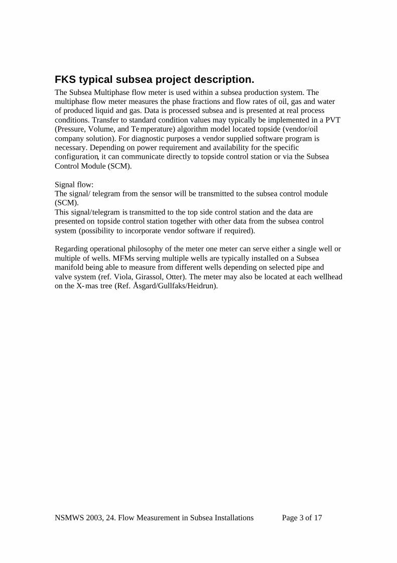
FKS typical subsea project description. The Subsea Multiphase flow meter is used within a subsea production system. The multiphase flow meter measures the phase fractions and flow rates of oil, gas and water of produced liquid and gas. Data is processed subsea and is presented at real process conditions. Transfer to standard condition values may typically be implemented in a PVT (Pressure, Volume, and Temperature) algorithm model located topside (vendor/oil company solution). For diagnostic purposes a vendor supplied software program is necessary. Depending on power requirement and availability for the specific configuration, it can communicate directly to topside control station or via the Subsea Control Module (SCM). Signal flow: The signal/ telegram from the sensor will be transmitted to the subsea control module (SCM). This signal/telegram is transmitted to the top side control station and the data are presented on topside control station together with other data from the subsea control system (possibility to incorporate vendor software if required). Regarding operational philosophy of the meter one meter can serve either a single well or multiple of wells. MFMs serving multiple wells are typically installed on a Subsea manifold being able to measure from different wells depending on selected pipe and valve system (ref. Viola, Girassol, Otter). The meter may also be located at each wellhead on the X-mas tree (Ref. Åsgard/Gullfaks/Heidrun).

NSMWS 2003, 24. Flow Measurement in Subsea Installations Page 4 of 17
Module mounted version: Vendor solution with the following main typical parts: Spool piece with flanges and instruments Electronics containment with flow computer, communication HW and additional HW related to the instrumentation for instance gamma detector. Blind T upstream the meter for flow conditioning purposes. Typically the sub-supplier of MFM provides only the basic design criteria’s for the blind-T.
MFM installed in Flow control Module

NSMWS 2003, 24. Flow Measurement in Subsea Installations Page 5 of 17
Retrievable version: The FMC Kongberg Subsea developed design of retrievable MFM for the Girassol project. The MFM is retrievable by means of lifting wire and handling /running tool supported by ROV. All instruments and the measuring section parts are retrievable. The locking mechanism toward the flowline is a propritary collet connector with FKS designed KX-seal. A module running tool (MRT) is used to operate the collet connector and retrieve/ install the MFM in vertical position. The MRT is guidelineless controlled and guided by ROV. The MRT system will interface the MFM through the modified API 17 D class 4 Docking-Latching-Rotary Unit. Latch/Unlatch and interlock function is mechanically operated by the ROV. Torque Tool for making-up the Module is handled and controlled from ROV.

NSMWS 2003, 24. Flow Measurement in Subsea Installations Page 6 of 17
All parts of the meter is inside the bucket upwards of the connector fingers. The stationary hub has an inlet and outlet including a blind T. This design provides the possibility of retrieving all instrumentation, electronics and sensitive as dp impulse lines and process exposed sensors. For these meters the MFM supplier provides the measuring section including sensors, electronics. FKS uses own design for the complete connector solution including MRT.
Lessons learned, Multiphase meters. There has been a strong marked pull from operators requesting subsea multiphase flow metering. This market pull have put restrictions on the time available for development for some MFMs. In addition the complexity of the MFMs with extensive use of specialised electronics and requirement for use non-metallic materials in order for the measurement principles to operate, have as one could predict opened for a number of potential new failure modes. It is our view that the trial and fail approach on the infant MFMs have contributed to establish best engineering practices for MFMs both for FKS and the suppliers of MFMs. However, at this stage it is of paramount importance that the system suppliers and the MFM suppliers use their accumulated experience and work together and implement best engineering practice established on this trial and fail period. From FKS perspective we focus on the following issues:
• Detail requirements and review of all material exposed to process and seawater. • Detail requirements and review of all sealing arrangements and possible leak
paths to process and seawater. • Focus on hydrate prevention; optimisation of dP measurements and cold spots. • Detail requirements and review of all qualification test and FAT tests.
We focus on the above and stresses that the MFM supplier have best competence for the measurement configuration and any detail that influences the measurement performance and measurement reliability: The measurement related sensors, electronics, SW and configuration is off course the MFM supplier domain.

NSMWS 2003, 24. Flow Measurement in Subsea Installations Page 7 of 17
CURRENT STATUS AND DEVELOPMENT We currently see a large span in the requirements and in the operational philosophy of the different operators of MFMs. This span have so far made it difficult to standardise on measurement specific MFM configurations. The spans are typically in the flow rate range over the field life time and among the wells. A large span in rates is often in conflict with the operator’s requirement for measurement performance. Temperature rating and GVF range vs. measurement performance is also a frequent issue. In addition there is continuously new developments from the suppliers. Also it have so far been difficult to comparable performance test of different meters.
MFM, for East Marimba Project, client CBV / Petrobras.

NSMWS 2003, 24. Flow Measurement in Subsea Installations Page 8 of 17
In summary we see a series of solution that lies between the two examples below: 1. Performance focused solution. Measurement performance requirements are tough. Higher price tolerance. Typically implemented in manifolds to replace top side test separators. Separately retrievable. 2. Low cost solution. One meter per well. Integrated in retrievable module. Preferably without use of gamma source that need replacement. From our experience it is a requirement that all parts of the MFM is retrievable either separately or in a retrievable module. We currently do not have enough field data to allow any part of the MFM to be stationary on the contrary. Technical aspects as the meters robustness, retrievability and minimum risk of failure plays a very important role in the FKS evaluations. Since the successful implementation and operation of MFM sometimes is conditional for a field development the operators frequently have preferences for suppliers, measurement principles and configuration of MFMs. FKS wants to be in a position making us able to constructively work together with operators and suppliers to find the best possible MFM for the operator’s application. At the same time FKS have off course to consider the standardisation and cost optimisation aspect.

NSMWS 2003, 24. Flow Measurement in Subsea Installations Page 9 of 17
Subsea Single Phase measurement Until 1998 FKS delivered Injection X-Mas trees was monitored by using choke data in conjunction with measured pressure and temperature drop over choke to calculate flow rates. In 1998 FKS met a requirement for more accurate Subsea single phase flow measurement from customers. FKS needed a simple, reliable, robust and cost effective Subsea flow meter which could be used for single phase measurement on applications such as water injection, gas re- injection and gas lift monitoring. Differential pressure meters such as Venturi and V-Cone were identified as suitable candidates to fulfil FKS requirements. Both types of flow meter were thoroughly evaluated to find the most suitable flow meter for integration in Subsea sys tems. After a closer evaluation was V-Cone found to be the most suitable flow meter for Subsea applications. This due to the fact that V-Cone requires “no” upstream and downstream straight pipe length and straight pipe runs are very often not available in subsea X-mas trees and manifolds. The V-Cone could also easily be standardised to a fixed short face to face length. This puts very little guidance on the layout of the equipment interfacing the V-Cone. One challenge by choosing the V-Cone was lack of references / experience with subsea applications and the fact that a subsea differential pressure transmitter that fulfilled FKS design philosophy was not commercially available. As a result of this fact was a Subsea version of the V-Cone flow meter, complete with a subsea DP-transmitter developed by two major vendors in cooperation with FKS. In addition to the dP signal we do provide line pressure and temperature from the adjacent sensors. There have been installed more than 70 V-Cone flow meters in FKS subsea systems delivered to the North Sea, Brazil, Western Africa, South Africa and Far East. Sizes delivered are from 2” to 6” comprising services as gas injection, gas lift, water injection and produced gas measurement. Pressure rating 5000 and 10.000psi. Max sea depth 2000meter. The last two years, approximate 25-30 off V-Cones per year have been installed in FKS equipment.

NSMWS 2003, 24. Flow Measurement in Subsea Installations Page 10 of 17
Photo: V-Cone meters for the Bao Bab project with dual set of dP transmitters.
Operational experience Based on field experience, the subsea DP-transmitter has been modified from original design. Current design has big bore vertical short length impulse tubes. This to prevent water accumulation, in impulse tubing and DP-transmitter for gas service flow meters. Gas flow measurement by subsea DP-devices is a non-trivial task. Ideally a subsea DP-device should have flush mounted remote seals on the sense lines to eliminate the risk of clogging or hydrate plugging. Water intrusion, from well completion and subsea installation, into Gas injection and gas lift flow meters have to be properly inhibited before gas service is started.

NSMWS 2003, 24. Flow Measurement in Subsea Installations Page 11 of 17
WET GAS METERS Wet Gas Venturi meters On the Statoil Mikkel field in the North Sea, FKS have integrated 2 off 10” Dualstream MKII wet gas venturi meters, in the subsea production system. The Mikkel field comprises two off production templates, and is a subsea tie back to the Åsgard B production platform. The 2 off Dualstream MK II meters serves as allocation meters for the Mikkel license. The decision of installing these meters was taken late in the Mikkel project phase, so it was not possible to integrate the meters in the Mikkel subsea manifolds and have electrical signal tie in to the manifold and well control modules. The Meters was integrated as a part of the tie-in spools, with one off control module per meter. One off Mikkel meter was tested/calibrated at full scale during Q1 2003 at Statoil K-Lab. Test production on the Mikkel field showed in general good conformance between the DualStream MK II meters and the V-Cone based Wet Gas Meters installed on each well. Production on the Mikkel Field is scheduled to start October 1st 2003.

NSMWS 2003, 24. Flow Measurement in Subsea Installations Page 12 of 17
. V-Cone based wet gas meter. FKS also served as the pilot integrator of the new compact subsea wet gas meters. The compact design allowed by the use of the V-cone as dP generating element enabled us to build the meter directly into our standard Flow Control Module (FCM) for our frame agreement projects with Statoil. Prior to the start of the Mikkel development project at FKS, Statoil had developed a prototype. We have delivered FCMs with WGMs for Statoils Mikkel and SVAN projects. In these projects the meters serves the function as the MFM does for lower GVF applications. For the new large subsea to land developments like Snøhvit and Ormen Lange it is essential to monitor small changes in the amounts of produced water and/or formation water. For these application the most challenging requirement is for the sensitivity of the water fraction measurement (high and low salinity)
SWGM for Statoil Mikkel Project.

NSMWS 2003, 24. Flow Measurement in Subsea Installations Page 13 of 17
Field experience wet gas. Field experience has shoved that measurement on gas producers is the most difficult application. Expected flow rates from subsea wells are not always easy to predict. This causes an uncertainty since the flow meter sizing will not be optimal. In the PetroSA, Mossgas E-M project in South Africa produced/condensed water from the well stream was accumulated in the impulse tubing and DP-transmitter, causing hydrate plugs putting the flow meter out of function. This problem was solved by building a heat conductive cast which enclosed both the V-Cone spool and the impulse tubing and DP-transmitter with an outer core of insulation material. This outer cover raised the temperature of the impulse tubing and DP-transmitter above hydrate equilibrium temperature during normal production, thus preventing hydrate formation in all process wetted parts of the V-Cone flow meter. For moderate/high temperature producer flow meters, thermal energy from the produced fluids could be used to raise the temperature of all process wetted parts above hydrate equilibrium temperature.

NSMWS 2003, 24. Flow Measurement in Subsea Installations Page 14 of 17
Quality aspects of subsea instruments (electronics).
Accuracy A common misconception is to confuse accuracy (and resolution) with quality. Facts are that delicacy increase with accuracy and lead to more frequent recalibration and even fault. High accuracy and thus drift problems is a major concern, and often we experience that drift per year exceeds the accuracy of the instrument. Some 4 to 20 mA instruments are digital inside, and present the measured value as an analogue current. However, to generate the signal with a 16 bit D/A converter (65436 increments) and to read the signal with a 12 bit A/D (4096 increments) converter, is by all means overkill. Another is when the required accuracy is better than the resolution. Subsea instruments should be kept at a reasonable accuracy for the application in question. Increasing the requirements only, result in increased price and faults.
Reliability and redundancies Redundancy is a way to ensure a “safe fail” situation. This is true when one instrument brakes, while the other is still working. However, at the end of the life cycle both have worked the same amount of time, have been exposed to same wear and tear, and are likely to suffer from same deficiencies. The life expectation is not increased and MTBF is decreased. Having a spare in sleep mode is not practical, and makes the system twice as expensive. A good way to apply redundancy is to analyze the whole system to see if one instrument can deputize for another provided they do the same job at different places in the same well stream. A bad way to apply redundancy is when you are not able to tell which instrument is correct.
Conclusion: Best practice, good quality components and good contingency plans are better than redundancy.

NSMWS 2003, 24. Flow Measurement in Subsea Installations Page 15 of 17
Appendix A
Idun Operation Support System Idun is a software-based operation support system with functions such as virtual flow metering, production flow rate control, production optimisation and production simulation. Functions are provided in both real-time and simulation mode, and allows for remote operation of wells. The remote operation was tested for a well on Troll Oil, being remotely operated from Vækerø, Oslo, for 24 hours in 1996. Idun calculates well flowrates at phase level both for producers, injectors, flowlines and gas -lift systems. Idun is capable of handling systems using artificial lift methods like gas lift and down-hole pumps, and optimises within limited resources for transport capacity, artificial lift or processing capacity. Idun is ideally suited for subsea field developments, particularly where complex subsea manifold and gathering systems are involved. It is also useful for dry applications supplementing conventional test separators. The flowrates are calculated based on input from sensors located along the individual well paths, like permanent down-hole and wellhead mounted sensors. It may utilise any flow-related measurements for this purpose.
Idun applies a mechanistic multiphase flow model in combination with a search algorithm to obtain the best possible fit between measured and Idun calculated sensor responses. The flowrates corresponding to this best fit represents the well flowrates. Alternative flow models are available at user request. The default Idun model has been verified against data from the Tiller experimental flow-loop in Trondheim. The system has been in active use since 1995. A schematic of a typical Idun installation is shown below in the figure below:
Time,Qliq, GOR
S
S
S
S
S
Inlet Separator
69 bar, 91CInlet Separator
Qg
Qo
Qw
SS
Dat
a A
cqui
sitio
n an
d C
ontr
ol
Pro
duct
ion
Dat
abas
e
Well Sensor DataP,T, Choke, etc.
Template DataP,T, Choke,
Meter Data, etc.
Rates
Choke Controller
IdunUser Interface
Schematic of Idun system indicating data flow between the computer hosting the Idun application and the
production control and data acquisition system.
Idun receives sensor data from the control system at a user specified frequency. For each set of received measurement data Idun calculates the associated well flowrates at phase level and returns these if required.

NSMWS 2003, 24. Flow Measurement in Subsea Installations Page 16 of 17
Any part of the production system can be used as measurement objects in Idun, most commonly used are the tubing and the chokes. The wells are normally very good measurement objects; due to the large pressure drop and temperature drop the sensitivity to sensor accuracy is small. The choke can have small dp and dT, and is more exposed to erosion. Focus has therefore been on using information from additional sensors, such as fraction meters and flow meters and Venturis. Initial calibration is necessary, although un-calibrated blind tests have been successful, to make sure that the flow model is representing the real system properly. The inherent difficulty with chokes may necessitate re-calibration of the choke model, following wear and tear. Comparisons with well tests or meters has been important as a diagnostics tool for operators, discovering depositions in production system due to discrepancies between Idun model predictions and tests. Idun is currently installed in 15 fields for 6 operators world wide, and the virtual metering function is used for more than 200 wells. Production flow rate control is used for more than 60 wells. Based in feedback from customers it appears that Idun functionality has been crucial in obtaining high, stable production rates for some of these fields. It is also important to realize that for all these fields, the instrumentation is insufficient to properly determine the system, and that the users must know either WC or GOR beforehand. For fields with more instrumentation, this is not necessary, and also additional functionality becomes available. When flow meters are installed, the systems are over-determined, and Idun can provide the operator with sensor and meter surveillance, increased fault tolerance, availability, and consistency of rates with fiscal or topside measurements. It is recommended to include permanent down-hole sensors in conjunction with Idun applications, but this not a prerequisite. In fact, if no such sensor is available Idun will perform a back-calculation, based on established flows, to find the corresponding down-hole pressure and temperature. In this way Idun is acting as a virtual down-hole sensor.
With the advent of new sensor types for permanent down-hole and wellhead applications Idun will get even more powerful. Such new sensors include fibre optic based systems for pressure, temperature, sonic velocity as well as volumetric flow, momentum sensor in combination with a sand detector as well as gas and water fraction sensors.

NSMWS 2003, 24. Flow Measurement in Subsea Installations Page 17 of 17
I
SSSS
SS
S
SS
S
SS
S
SS
Petroleum productionsystem Measurements
Model
Model tuning Control,
optimization and monitoring
AutomaticControl signals
Modeled measurements
Model correction
Model error/ measurement error
• Corrected measurements• Estimated important
variables not measured
Operation support
IDUN operation support system
Idun Operation Support System logic; measurements and models combined give improved res ults.

References
[1] Paper presented at the North Sea Flow Measurement Workshop, a workshoparranged by NFOGM & TUV-NEL
Note that this reference was not part of the original paper, but has been addedsubsequently to make the paper searchable in Google Scholar.