Embed Size (px)
Citation preview
1 Pantera Electronics Rev. 02/05/2018
Pantera Electronics USB Dual Charging Port Installation Manual
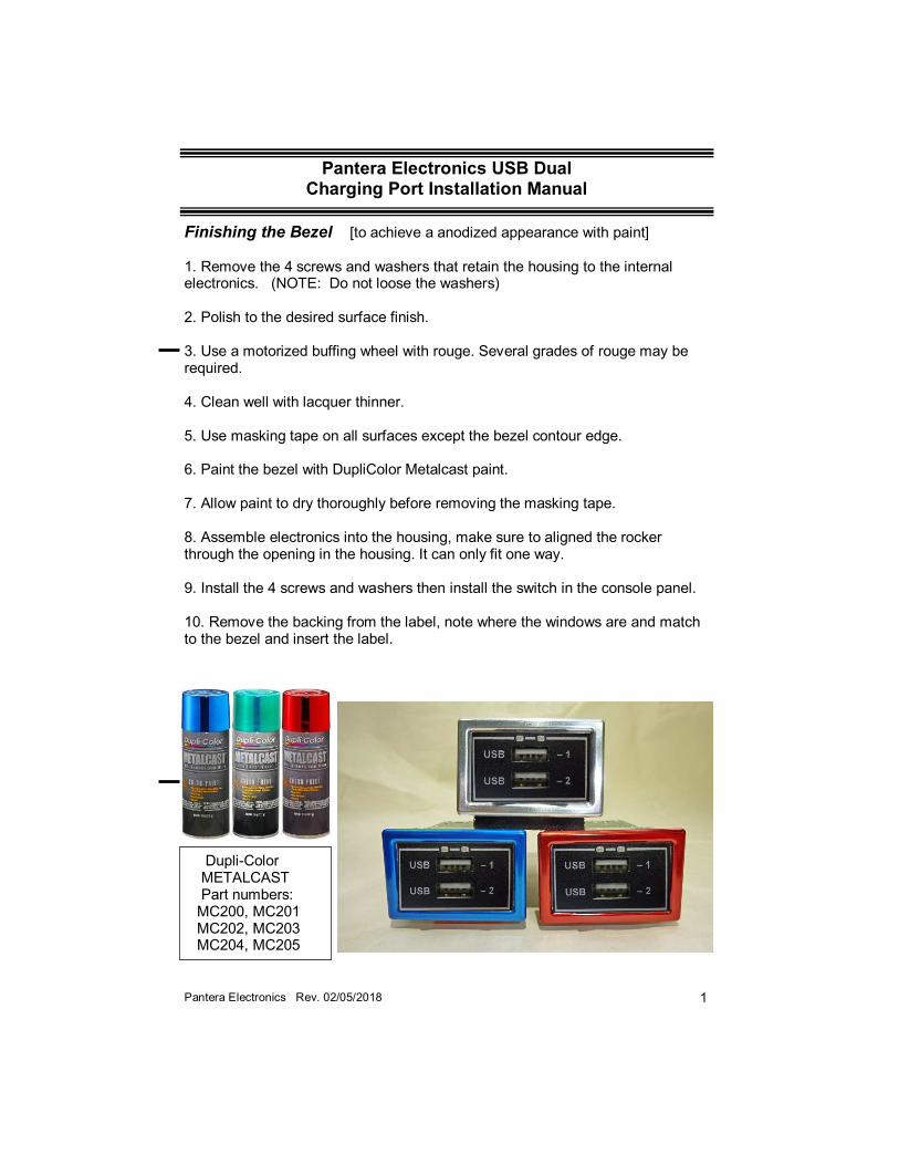
Dupli-Color METALCAST Part numbers: MC200, MC201 MC202, MC203 MC204, MC205
Finishing the Bezel [to achieve a anodized appearance with paint] 1. Remove the 4 screws and washers that retain the housing to the internal electronics. (NOTE: Do not loose the washers) 2. Polish to the desired surface finish. 3. Use a motorized buffing wheel with rouge. Several grades of rouge may be required. 4. Clean well with lacquer thinner. 5. Use masking tape on all surfaces except the bezel contour edge. 6. Paint the bezel with DupliColor Metalcast paint. 7. Allow paint to dry thoroughly before removing the masking tape. 8. Assemble electronics into the housing, make sure to aligned the rocker through the opening in the housing. It can only fit one way. 9. Install the 4 screws and washers then install the switch in the console panel. 10. Remove the backing from the label, note where the windows are and match to the bezel and insert the label.
2 Pantera Electronics Rev. 02/05/2018
Disconnect the Battery by removing the negative (-) or ground cable from the battery terminal.
1.Unscrew the 3 thumb screws that retain the console gauge plate. 2. Disconnect any wires from the back of the factory Auxiliary switch and push the switch out of the panel, this may require rocking the switch out of the hole. [See page 9] 3. Make sure the hole is free from the black surface material, it cannot be inside the hole or the Dual Charger Port will not fit. 4. There are several different hole configurations of the openings in the console plates. (1971 / 72) console plate may require the corners to be modified by filing the corner to remove the alignment corners. This can done with a sharp flat file or Dremel tool with a grinding disk for the metal console plates. The (1973 / 74) plastic console plates can be easily cut with a knife and does not require use of a Dremel tool. 5. Check the fit of the Dual Charger Port in the hole, make sure that it can sit flat and even against the console plate. [See page 9] 6. Slide the O-ring over the back of the Dual Charger Port until it’s about 3/8” from the back of the aluminum mounting flange. 7. Insert the Dual Charger Port in the hole by tilting the switch to allow the O-ring to fit through the hole. Then slide the O-ring into the groove on the flange. Use a long straight blade screwdriver to push the O-ring. 8. Connect the wires adding wire to the tabs labeled with where the wires need to connect. [See page 6] 9. Connect the Yellow/Black wire for the lighting. See page 4. 10. Reconnect the battery ground cable. 11. Test the Dual Charger Port and check to make sure it illuminates when the lights are “ON”. 12. Reassemble the console panel and thumb screws and re-test the Dual Charger Port. [See page 8, Dual Charger Port Operation]
3 Pantera Electronics Rev. 02/05/2018
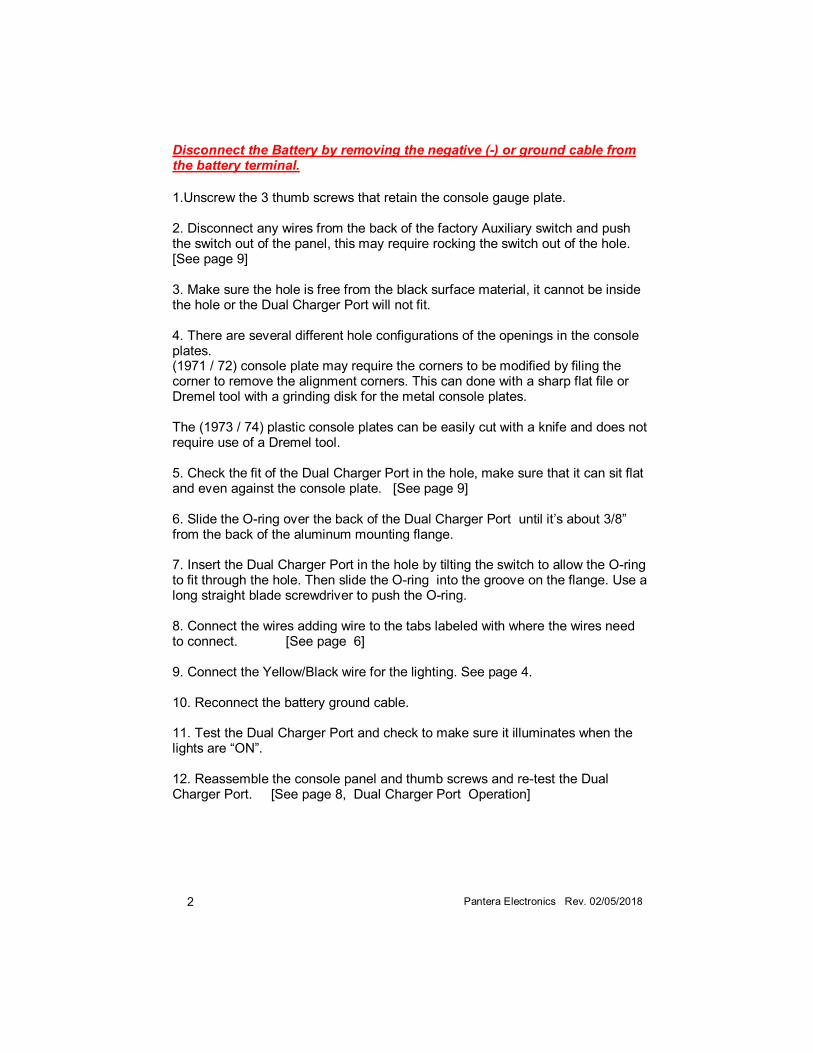
This alignment corner configuration needs to be removed.
O-ring position for installation. Approximately 3/8” space
Tilt Dual Charger Port in both directions to pass the O-ring through.
4 Pantera Electronics Rev. 02/05/2018
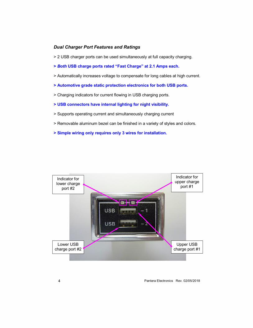
Dual Charger Port Features and Ratings > 2 USB charger ports can be used simultaneously at full capacity charging. > Both USB charge ports rated “Fast Charge” at 2.1 Amps each. > Automatically increases voltage to compensate for long cables at high current. > Automotive grade static protection electronics for both USB ports. > Charging indicators for current flowing in USB charging ports. > USB connectors have internal lighting for night visibility. > Supports operating current and simultaneously charging current > Removable aluminum bezel can be finished in a variety of styles and colors. > Simple wiring only requires only 3 wires for installation.
Indicator for lower charge
port #2
Lower USB charge port #2
Upper USB charge port #1
Indicator for upper charge
port #1
5 Pantera Electronics Rev. 02/05/2018
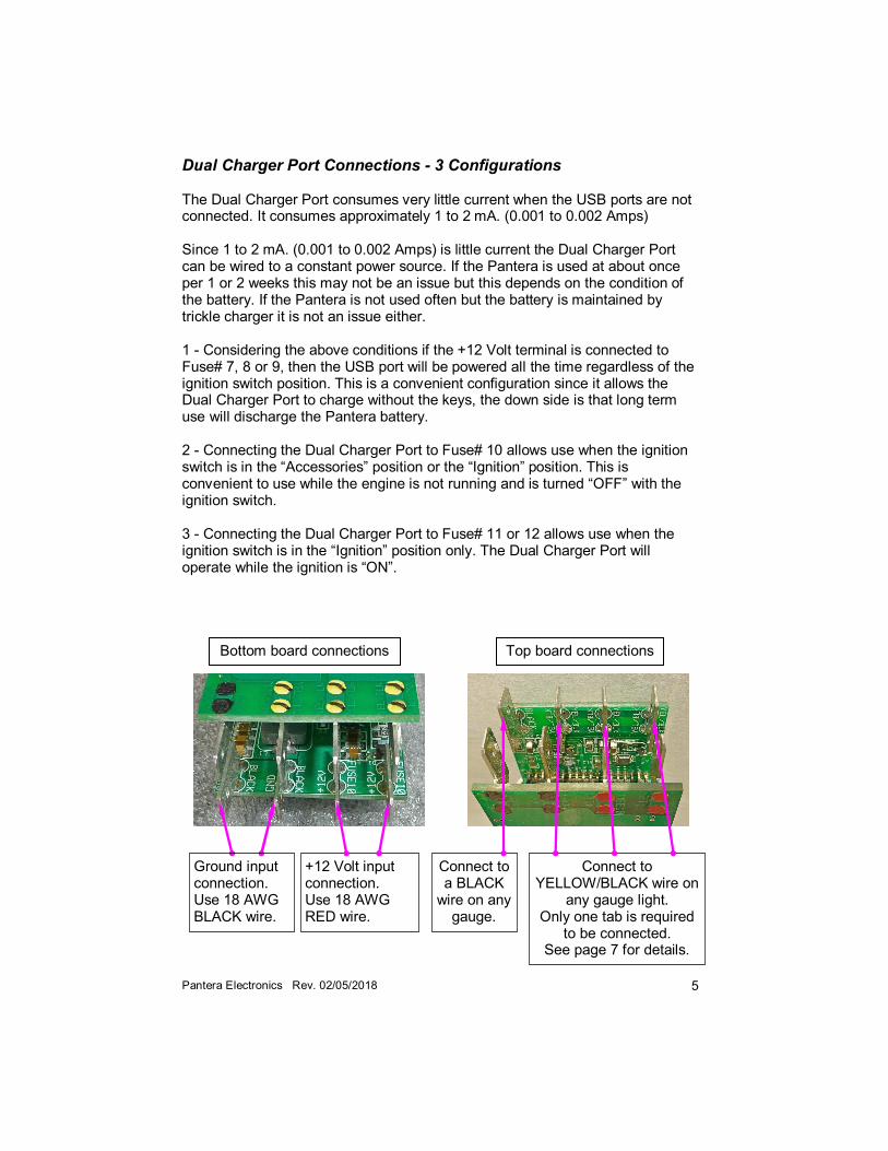
Dual Charger Port Connections - 3 Configurations The Dual Charger Port consumes very little current when the USB ports are not connected. It consumes approximately 1 to 2 mA. (0.001 to 0.002 Amps) Since 1 to 2 mA. (0.001 to 0.002 Amps) is little current the Dual Charger Port can be wired to a constant power source. If the Pantera is used at about once per 1 or 2 weeks this may not be an issue but this depends on the condition of the battery. If the Pantera is not used often but the battery is maintained by trickle charger it is not an issue either. 1 - Considering the above conditions if the +12 Volt terminal is connected to Fuse# 7, 8 or 9, then the USB port will be powered all the time regardless of the ignition switch position. This is a convenient configuration since it allows the Dual Charger Port to charge without the keys, the down side is that long term use will discharge the Pantera battery. 2 - Connecting the Dual Charger Port to Fuse# 10 allows use when the ignition switch is in the “Accessories” position or the “Ignition” position. This is convenient to use while the engine is not running and is turned “OFF” with the ignition switch. 3 - Connecting the Dual Charger Port to Fuse# 11 or 12 allows use when the ignition switch is in the “Ignition” position only. The Dual Charger Port will operate while the ignition is “ON”.
Bottom board connections Top board connections
+12 Volt input connection. Use 18 AWG RED wire.
Connect to YELLOW/BLACK wire on
any gauge light. Only one tab is required
to be connected. See page 7 for details.
Ground input connection. Use 18 AWG BLACK wire.
Connect to a BLACK
wire on any gauge.
6 Pantera Electronics Rev. 02/05/2018
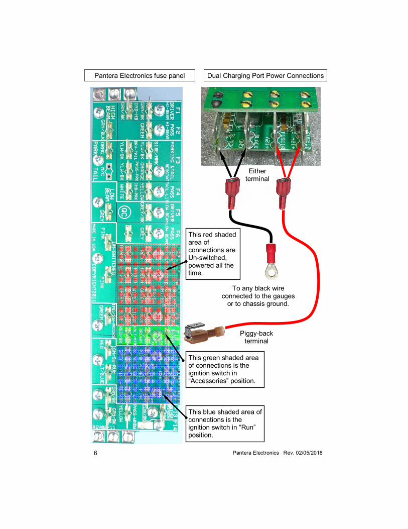
To any black wire connected to the gauges
or to chassis ground.
This green shaded area of connections is the ignition switch in “Accessories” position.
This red shaded area of connections are Un-switched, powered all the time.
This blue shaded area of connections is the ignition switch in “Run” position.
Piggy-back terminal
Pantera Electronics fuse panel Dual Charging Port Power Connections
Either terminal
7 Pantera Electronics Rev. 02/05/2018
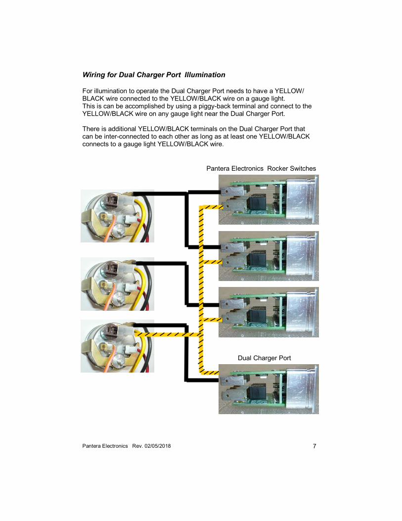
Wiring for Dual Charger Port Illumination For illumination to operate the Dual Charger Port needs to have a YELLOW/BLACK wire connected to the YELLOW/BLACK wire on a gauge light. This is can be accomplished by using a piggy-back terminal and connect to the YELLOW/BLACK wire on any gauge light near the Dual Charger Port. There is additional YELLOW/BLACK terminals on the Dual Charger Port that can be inter-connected to each other as long as at least one YELLOW/BLACK connects to a gauge light YELLOW/BLACK wire.
Dual Charger Port
Pantera Electronics Rocker Switches
8 Pantera Electronics Rev. 02/05/2018
Dual Charger Port Operation 1. Depending on the configuration of wiring was selected on page 5, turn “ON” the Dual Charger Port . 2. There isn't an indication that the Dual Charger Port is powered, the 2 green lights on the face indicate that a cell phone or other USB device is connected and using power. 3. Plug in a USB a device, modern cell phones will communicate with the Dual Charger Port to establish a proper charge current. The indicator will flash during this period and can last long as 20 seconds. At some point the indicator will be illuminated steadily and charging begins. 4. Typically the indicator will turn “OFF” when the cell phone is completely charged, but some cell phones will continue to communicate and the indicator will flicker or will still be illuminated. 5. When a device is left plugged in the Dual Charger Port will maintain the device battery at full charge even when in use. This is important when using a cell phone for navigation or playing music which has high current demand. 6. Modern cell phones can store hours of music and provide a player that will output audio from the phone jack or as Bluetooth communication. This is a compact and flexible means to play music without having to mount large auto stereo unit in the already crowded console. An audio amplifier can be mounted remotely to boost the audio level from the cell phone to compete with the exhaust system “music”. 7. The indicator will turn “OFF” when the USB device plug is removed.
Note: The charger port bezel may be warm to the touch, during very high charging rates this is normal during operation.
9 Pantera Electronics Rev. 02/05/2018
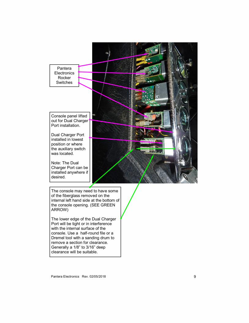
Console panel lifted out for Dual Charger Port installation. Dual Charger Port installed in lowest position or where the auxiliary switch was located. Note: The Dual Charger Port can be installed anywhere if desired.
Pantera Electronics
Rocker Switches
The console may need to have some of the fiberglass removed on the internal left hand side at the bottom of the console opening. (SEE GREEN ARROW) The lower edge of the Dual Charger Port will be tight or in interference with the internal surface of the console. Use a half-round file or a Dremel tool with a sanding drum to remove a section for clearance. Generally a 1/8” to 3/16” deep clearance will be suitable.
10 Pantera Electronics Rev. 02/05/2018
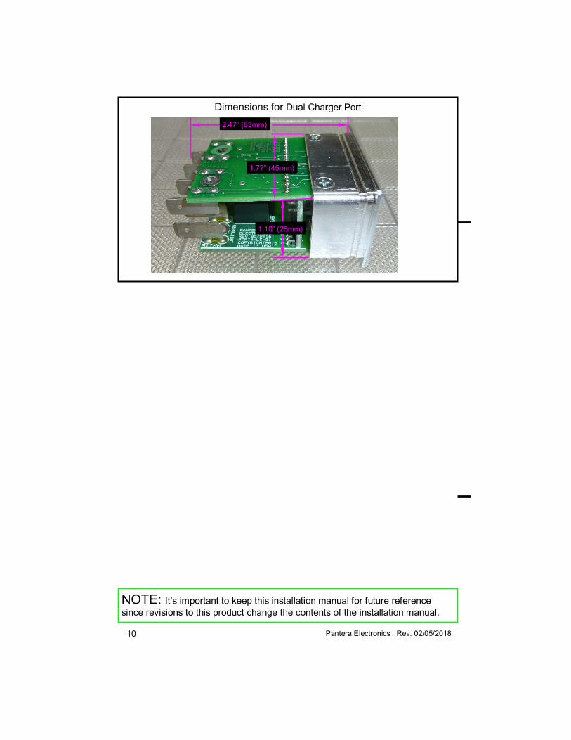
Dimensions for Dual Charger Port
1.10” (28mm)
1.77” (45mm)
2.47” (63mm)
NOTE: It’s important to keep this installation manual for future reference
since revisions to this product change the contents of the installation manual.