Embed Size (px)
Citation preview
1 Pantera Electronics Rev. 06/22/2018
Pantera Electronics Ignition Switch Controller Installation Manual
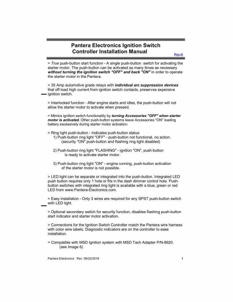
> True push-button start function - A single push-button switch for activating the starter motor. The push-button can be activated as many times as necessary without turning the ignition switch "OFF" and back "ON" in order to operate the starter motor in the Pantera. > 35 Amp automotive grade relays with individual arc suppression devices that off-load high current from ignition switch contacts, preserves expensive ignition switch. > Interlocked function - After engine starts and idles, the push-button will not allow the starter motor to activate when pressed. > Mimics ignition switch functionality by turning Accessories "OFF" when starter motor is activated. Other push-button systems leave Accessories "ON" loading battery excessively during starter motor activation.
> Ring light push-button - Indicates push-button status: 1) Push-button ring light "OFF" - push-button not functional, no action. (security "ON" push-button and flashing ring light disabled) 2) Push-button ring light "FLASHING" - ignition "ON", push-button is ready to activate starter motor. 3) Push-button ring light "ON" - engine running, push-button activation of the starter motor is not possible. > LED light can be separate or integrated into the push-button. Integrated LED push button requires only 1 hole or fits in the dash dimmer control hole. Push-button switches with integrated ring light is available with a blue, green or red LED from www.Pantera-Electronics.com. > Easy installation - Only 3 wires are required for any SPST push-button switch with LED light. > Optional secondary switch for security function, disables flashing push-button start indicator and starter motor activation. > Connections for the Ignition Switch Controller match the Pantera wire harness with color wire labels. Diagnostic indicators are on the controller to ease installation. > Compatible with MSD Ignition system with MSD Tach Adapter P/N-8920. (see Image 6)
Rev6
2 Pantera Electronics Rev. 06/22/2018
Additional supplies you will need: Wire - 16 AWG in YELLOW, RED, BLACK. Wire - 20 AWG in ORANGE, GREY, BLACK, VIOLET (optional) Quick disconnect terminals - YELLOW for 10 - 12 gauge wire Quick disconnect terminals - BLUE for 14 - 16 gauge wire Quick disconnect terminals - RED for 18 - 22 gauge wire
Optional up-grade: Terminal Strip is available from PE, part # 4TS. [Page 10] Note: the Ignition Switch Controller will be referenced as ISC for the remainder of this manual.
Disconnect the battery by removing the negative (-)
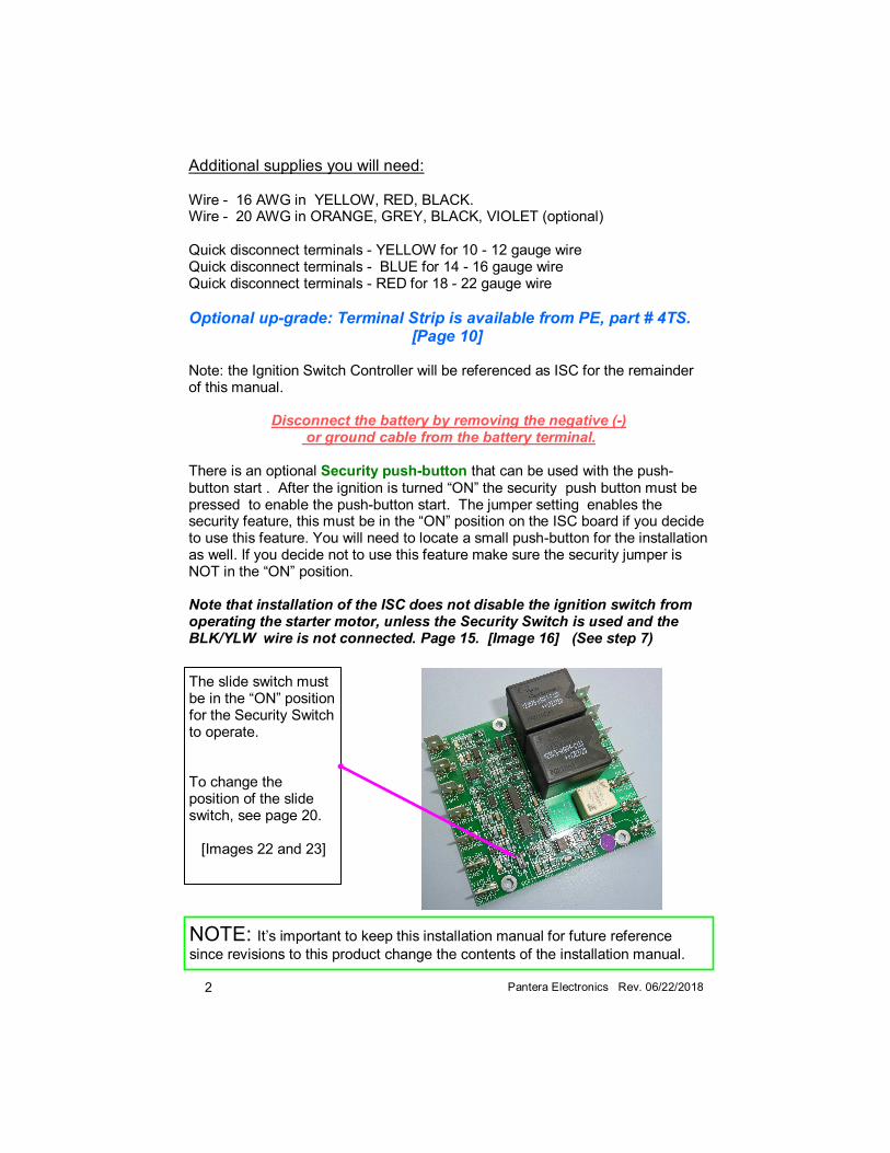
or ground cable from the battery terminal. There is an optional Security push-button that can be used with the push-button start . After the ignition is turned “ON” the security push button must be pressed to enable the push-button start. The jumper setting enables the security feature, this must be in the “ON” position on the ISC board if you decide to use this feature. You will need to locate a small push-button for the installation as well. If you decide not to use this feature make sure the security jumper is NOT in the “ON” position. Note that installation of the ISC does not disable the ignition switch from operating the starter motor, unless the Security Switch is used and the BLK/YLW wire is not connected. Page 15. [Image 16] (See step 7)
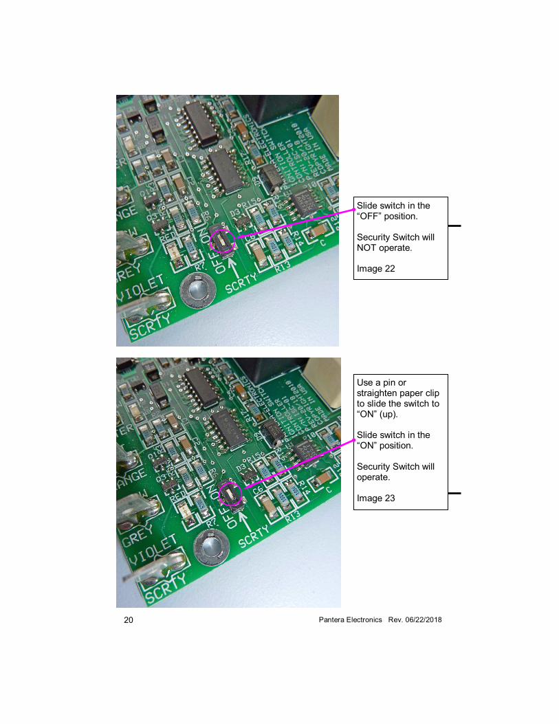
The slide switch must be in the “ON” position for the Security Switch to operate. To change the position of the slide switch, see page 20. [Images 22 and 23]
NOTE: It’s important to keep this installation manual for future reference
since revisions to this product change the contents of the installation manual.
3 Pantera Electronics Rev. 06/22/2018
Installation 1) Remove (4) 8mm bolts that support the steering column, rest the steering wheel on the drivers seat. [Image 1] 2) Find the 4 wire factory terminal block, start by removing the 4 wires from the original terminal block to the Pantera wire harness. Use tape to group the LARGE RED wire and SMALL PINK (or RED depending on the year) wire together. Remove any factory tape or insulation and cut the wires apart. [Image 2] 3) Crimp (3) YELLOW (10 AWG) quick disconnect terminals on the LARGE RED, large PINK and other LARGE RED wire. Crimp (2) BLUE (12 AWG) quick disconnect terminal on the GREEN, PINK or RED wire. (depending on the year) [Image 3] 4) Pull the Pantera harness from the back side of the dash to move the end of the harness to a lower position outside of the steering column bracket. [Image 3] 5) On the back side of the Tach there is a BLUE wire with a quick disconnect terminal. Remove the BLUE wire and add the link to the quick disconnect terminal. 6) Crimp a BLUE (16 AWG) quick disconnect terminal on a BLUE (16 AWG) wire and connect to the male quick disconnect terminal to the link. At this point there should be the factory BLUE/BLACK stripe wire and the additional BLUE wire linked together with a female position on the link to install on the back of the Tach were the original BLUE/BLACK stripe wire was connected. Make this connection to the back of the Tach and leave the other end of the BLUE wire loose. [Image 4&5]
Very Important! When crimping the quick disconnect terminals only use the proper crimping tool. Pliers, Channel locks and Vice-grips do not crush the terminal jacket properly. These are high current connections, in excess of 30 amps and can cause fire if improperly crimped. YOU HAVE BEEN WARNED !
CAUTION Factory windshields are notorious for water leaks. The water collects in the gasket relief and slowly drips from the inside of the gasket area and falls vertically. If this water contacts the ISC it will cause failure of the electronics and may cause the ISC to operate in a erratic manor including unpredictable starter motor operation. Seal all leaks and verify that water cannot contact the ISC in the selected mounting location.
4 Pantera Electronics Rev. 06/22/2018
Note: Connecting the Tach wire maybe difficult on the back of the tachometer especially on 1973 and 1974 “single pod” dash boards. Alternately the Tach connection for the ISC can be connected to the BLUE/BLACK wire in the engine bay. The BLUE/BLACK wire is connected to the ignition coil on the (-) coil stud. The Tach wire for the ISC can be connected to the (-) coil stud as well. Note: If you have an MSD ignition system with MSD Tach Adapter the PURPLE wire is the connected for the tachometer. Usually the PURPLE wire is connected to the BLUE/BLACK wire in the Pantera wire harness which is connected to the tachometer. Alternately you can connect the ISC “TACH” tab to the MSD Tach Adapter PURPLE wire connection to the BLUE/BLACK wire in the engine bay. This maybe physically easier than making the connection to the back of the tachometer especially on 1973 and 1974 “single pod” dash boards. [Image 6] 7) Construct a cable harness with 4 wires, 18 inches long, either label the wires or use YELLOW, RED, BLACK and BLACK (YELLOW tag) wires. The wires size should be 16 AWG, this is smaller gauge wire than the original wire but it does not matter since the ISC has little current flowing between it and the ignition switch. Wrap tape or use a WIRE jacket to complete the harness construction. Crimp (4) BLUE (16 AWG) quick disconnect terminals on each of the wires. [Image 8]
Note: Do NOT connect the BLK/YLW position if using the Security Switch option, it will defeat the purpose of having a Security Switch. [Image 16]
8) Connect the constructed cable harness wires to the quick disconnect tabs on the ISC side with the wire color sequence: [Image 8&9]
| YLW | BLACK | RED | BLK/YLW | ORANGE | GREY | VIOLET |
9) The other end of the harness connects to the factory terminal block on the steering column in the same sequence as the original factory wires that were removed in step 2. If you used the same color wires just match the colors. 10) Connect the (4) wire Pantera harness with the quick disconnect tabs on the ISC side with the wire color sequence: [Image 7]
| GREEN | PINK / RED | PINK | RED | BLACK | BLUE |
5 Pantera Electronics Rev. 06/22/2018
11) Crimp a RED quick disconnect terminal on a ORANGE (20 AWG) wire and connect to the terminal labeled “ORANGE” on the ISC and leave the other end of the ORANGE wire loose. [Image 16] 12) Crimp a RED quick disconnect terminal on a GREY (20 AWG) wire and connect to the terminal labeled “GREY” on the ISC and leave the other end of the GREY wire loose. [Image 16] 13) Step 14 is only needed if you are using the Security push-button feature. Crimp a RED quick disconnect terminal on a VIOLET (20 AWG) wire and connect to the male quick disconnect terminal labeled “VIOLET” on the ISC and leave the other end of the VIOLET wire loose. [Image 16] 14) Remove the left hand side of the kick panel on the console. Remove the instrument cluster dimmer control located in the console. Un-screw the retaining ring from outside of the dimmer adjustment knob. The dimmer should drop out of the hole and (2) wires should be connected to it, ORANGE and YELLOW. These wires can be removed from the dimmer and connected together, this will maintain the gauge lights at full brightness. (1971 & 1972) Insulate the connectors with tape (1973 & 1974) if connected to the lights above the console. The dimmer hole is slightly under-sized for the push-button and needs to have the “flat” inside the hole removed by filling a radius in the hole. This should open the hole enough for the push-button to fit. [Image 21] If you want to keep the dimmer control in the console then locate a suitable location to mount the push-button start switch and drill a 3/4” diameter hole for mounting. 15) Feed the ORANGE (20 AWG) and GREY (20 AWG) wires (steps 11 & 12) through the retaining nut of the push-button and the console. Then strip the wire about a 1/4” and connect the wires to the proper location on the back of the push-button. [Images 13&15] 16) Add a small jumper wire to (2) of the push-button terminals. Feed a BLACK (20 AWG) wire through the retaining nut of the push-button and the console. Then strip the wire about a 1/4”.and connect the wire to the proper location on the back of the push-button. The BLACK wire can share one of the screw terminals with the jumper wire. [Image 11&12]
Note: Make sure the push button wiring is correct, the internal LED can be damaged and IS NOT repairable.
6 Pantera Electronics Rev. 06/22/2018
Note: A jacket or electrical tape can be used to make a harness for the (3) push-button switch wires. [Image 17] 17) Use the nut to retain the push-button switch in the hole. [Image 17 & 21] 18) Connect the VIOLET (20 AWG) wire from step 13 to the push-button to be used as the security push-button. The other connection for the Security Push-button connects to chassis ground. [Image 16 & 18] 19) Mount the Security Push-button in hidden but convenient place, connect the VIOLET wire to one of the switch terminals. Crimp a RED ring lug terminal to a BLACK 20 AWG wire and connect to the other Security Switch terminal. Find a nearby ground stud or screw to attach the ring terminal to chassis ground or drill a hole in a convenient location in the sheet metal, the hole should be slightly smaller the self tapping screw size. Use a self-tapping screw and mount the ring terminal and insulate as required. 20) Strip the insulation from a BLACK (20 AWG) wire and twist the BLACK (20 AWG) wire from the push-button switch and crimp a BLUE quick disconnect terminal on both wires. Then connect to the tab labeled “BLACK” and “GND” on the ISC. This wire will be the ground connection for both the push-button switch and the ISC. [Image 16 & 19] 21) The other end of the BLACK (20 AWG) wire crimp a RED ring lug terminal to the BLACK (20 AWG) wire. Find a nearby ground stud or screw to attach the ring terminal to for chassis ground. If needed drill a hole and use a sheet metal screw to mount the terminal. [Image 17] 22) Mount the ISC in a convenient location for the wires, if needed “warm” the heavy wires with a hair dryer to allow them to bend. [Image 17 & 19] 23) Lift steering column and replace the 4 bolts. [Image 1]
IMPORTANT If mounting the ISC with screws through the 3 mounting holes, use 1/4” long spacers to raise the board from the mounting surface. Do not mount the ISC board tightly to any surface.
7 Pantera Electronics Rev. 06/22/2018
Testing - Note use this testing procedure if the decision was to not use the Security Switch option. (Page 2)
1) Connect the negative (-) or ground cable to the battery terminal.
2) With the key in the ignition switch, rotate the switch to the “ACCESSORIES” position. Note the yellow indicator on the ISC will be illuminated. 3) Check the heater blower or headlight motor (up/down) operation to determine if those accessories are operational. 4) Rotate the ignition switch to the “RUN” position. Note the green indicator on the ISC will be illuminated. 5) Check the brake lights, power windows or gauges to determine if they are operational. 6) Rotate the ignition switch to the “START” position. The starter motor should operate and the engine should fire and run. Note the blue indicator on the ISC will be illuminated during starter motor activation. 7) Press the start push-button and the starter motor should activate. After releasing the push-button with the engine running the push-button ring light should be “ON” steadily. If the engine did not run and a re-start of the starter motor is needed, the push-button ring light will be flashing to enable another starter motor attempt. Note: The yellow indicator will turn “OFF” during starter motor activation. 8) After the engine is running the push-button ring light should be “ON” steadily and additional presses of the push-button will not engage the starter motor. 9) Rotate the ignition switch to “OFF” and all functions should be off. 10) Testing complete.
Testing - Note use this testing procedure if the decision was to use the Security Switch option. (Page 2) 1) Connect the negative (-) or ground cable to the battery terminal. 2) With the key in the ignition switch, rotate the switch to the “ACCESSORIES” position. Note: the yellow indicator on the ISC will be illuminated.
8 Pantera Electronics Rev. 06/22/2018
Disclaimer The products from Pantera Electronics have been designed and manufactured with the best quality components known to the engineer. The installation instructions have been written to assist the owner in the proper use and installation of the products. Pantera Electronics can not be held responsible or held liable for the interpretation or incorrect implementation of the products.
3) Check the heater blower or headlight motor (up/down) operation to determine if those accessories are operational. 4) Rotate the ignition switch to the “RUN” position. Note the green indicator on the ISC will be illuminated. 5) Check the brake lights, power windows or gauges to determine if they are operational. 6) Rotate the ignition switch to the “START” position. The starter motor should NOT operate. Note the blue indicator on the ISC will NOT illuminate during a starter motor attempt. 7) Press the Security push-button and the start push-button ring light should be flashing. Note the RED indicator on the ISC will be illuminated only when the push-button is pressed. 8) Press the start push-button and the starter motor should activate. After releasing the push-button with the engine running the push-button ring light should be ”ON” steadily. If the engine did not run and a re-start of the starter motor is needed the push-button ring light will be flashing to enable another starter motor attempt. Note: The yellow indicator will turn “OFF” during starter motor activation. 9) After the engine is running the push-button ring light will be “ON” steadily and additional presses of the push-button will not engage the starter motor. 10) Rotate the ignition switch to “OFF” and all functions should be off. 11) If the ignition switch is turn “OFF” and back “ON” the Security push-button will have to be pressed to activate the push-button ring light. 12) Testing complete.
9 Pantera Electronics Rev. 06/22/2018
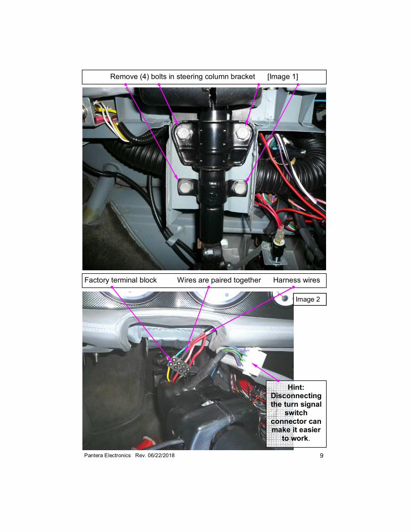
Remove (4) bolts in steering column bracket [Image 1]
Factory terminal block Wires are paired together Harness wires
Hint: Disconnecting the turn signal
switch connector can make it easier
to work.
Image 2
10 Pantera Electronics Rev. 06/22/2018
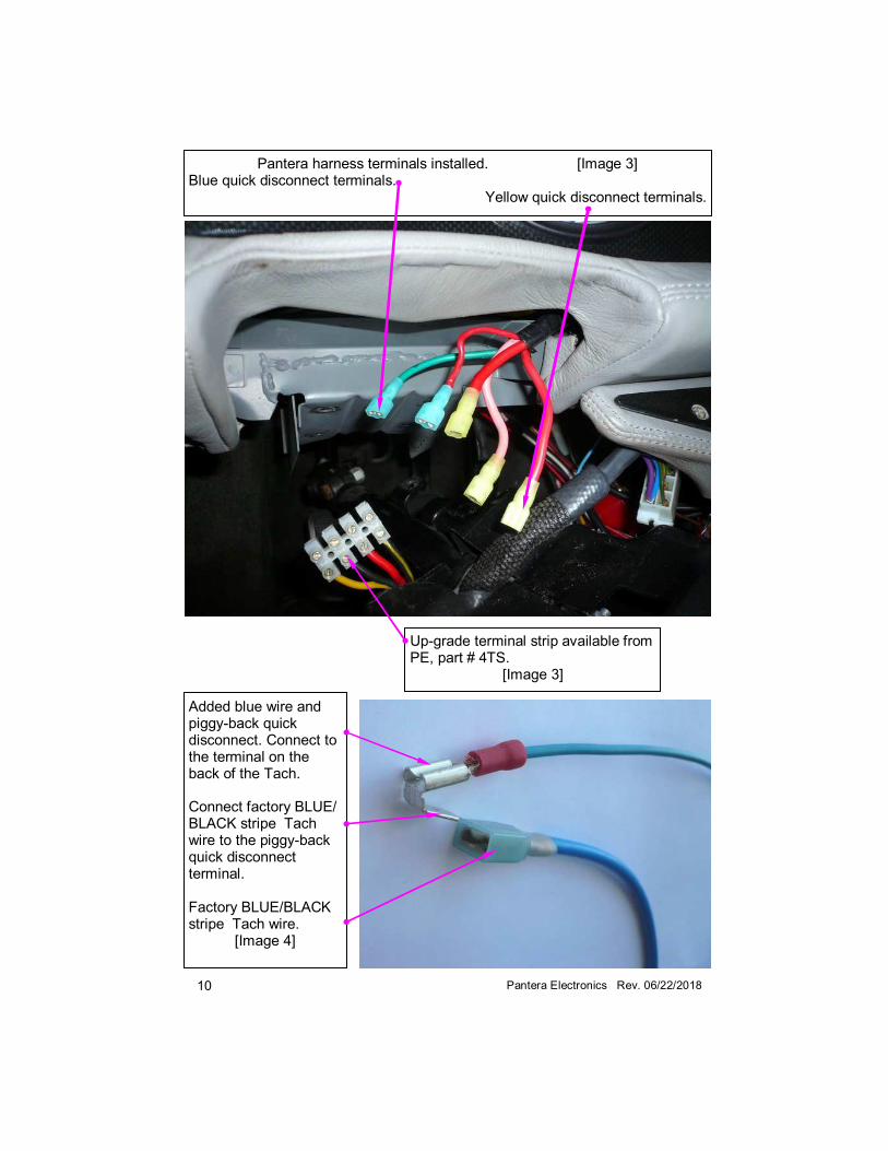
Pantera harness terminals installed. [Image 3] Blue quick disconnect terminals.
Yellow quick disconnect terminals.
Added blue wire and piggy-back quick disconnect. Connect to the terminal on the back of the Tach.
Connect factory BLUE/BLACK stripe Tach wire to the piggy-back quick disconnect terminal.
Factory BLUE/BLACK stripe Tach wire.
[Image 4]
Up-grade terminal strip available from PE, part # 4TS.
[Image 3]
11 Pantera Electronics Rev. 06/22/2018
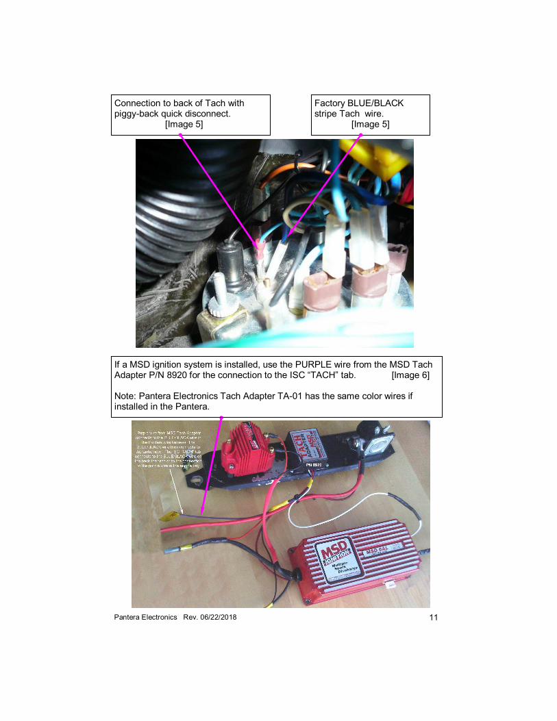
Connection to back of Tach with piggy-back quick disconnect. [Image 5]
If a MSD ignition system is installed, use the PURPLE wire from the MSD Tach Adapter P/N 8920 for the connection to the ISC “TACH” tab. [Image 6] Note: Pantera Electronics Tach Adapter TA-01 has the same color wires if installed in the Pantera.
Factory BLUE/BLACK stripe Tach wire.
[Image 5]
12 Pantera Electronics Rev. 06/22/2018
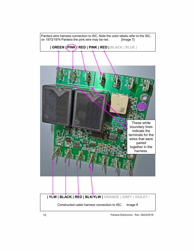
Pantera wire harness connection to ISC, Note the color labels refer to the ISC, on 1973/1974 Pantera the pink wire may be red. [Image 7]
| GREEN | PINK / RED | PINK | RED | BLACK | BLUE |
| YLW | BLACK | RED | BLK/YLW | ORANGE | GREY | VIOLET |
Constructed cable harness connection to ISC. Image 8
These white boundary lines
indicate the terminals for the wires that were
paired together in the
harness.
13 Pantera Electronics Rev. 06/22/2018
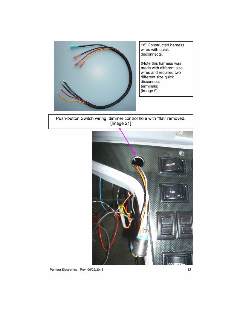
18” Constructed harness wires with quick disconnects. (Note this harness was made with different size wires and required two different size quick disconnect terminals) [Image 9]
Push-button Switch wiring, dimmer control hole with “flat” removed. [Image 21]
14 Pantera Electronics Rev. 06/22/2018
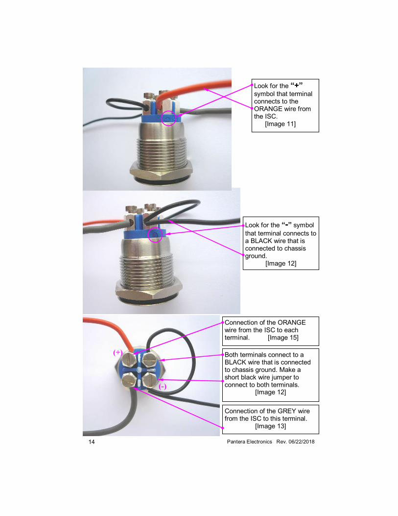
(+)
(-)
Look for the “+”
symbol that terminal connects to the ORANGE wire from the ISC. [Image 11]
Connection of the GREY wire from the ISC to this terminal.
[Image 13]
Look for the “-” symbol
that terminal connects to a BLACK wire that is connected to chassis ground.
[Image 12]
Connection of the ORANGE wire from the ISC to each terminal. [Image 15]
Both terminals connect to a BLACK wire that is connected to chassis ground. Make a short black wire jumper to connect to both terminals.
[Image 12]
15 Pantera Electronics Rev. 06/22/2018
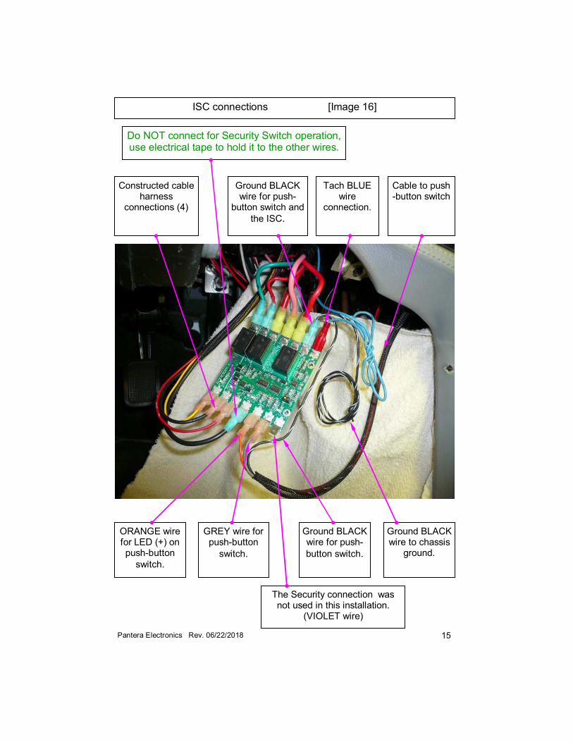
ISC connections [Image 16]
ORANGE wire for LED (+) on push-button
switch.
GREY wire for push-button
switch.
Ground BLACK wire for push-
button switch.
Constructed cable harness
connections (4)
Ground BLACK wire for push-
button switch and
the ISC.
Tach BLUE wire
connection.
Ground BLACK wire to chassis
ground.
The Security connection was not used in this installation.
(VIOLET wire)
Cable to push-button switch
Do NOT connect for Security Switch operation, use electrical tape to hold it to the other wires.
16 Pantera Electronics Rev. 06/22/2018
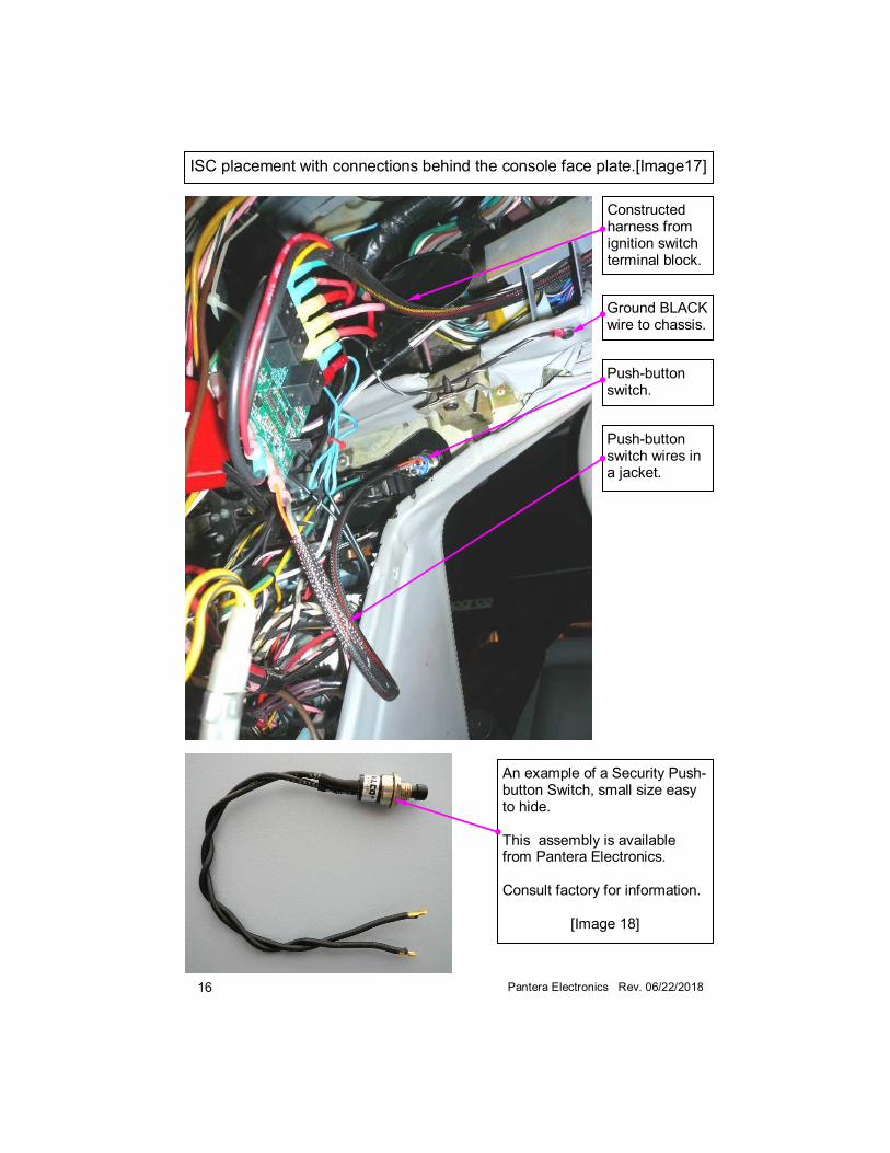
An example of a Security Push-button Switch, small size easy to hide. This assembly is available from Pantera Electronics. Consult factory for information.
[Image 18]
Constructed harness from ignition switch terminal block.
Ground BLACK wire to chassis.
Push-button switch.
Push-button switch wires in a jacket.
ISC placement with connections behind the console face plate.[Image17]
17
Pan
tera
Ele
ctro
nic
s R
ev. 0
6/2
2/2
018
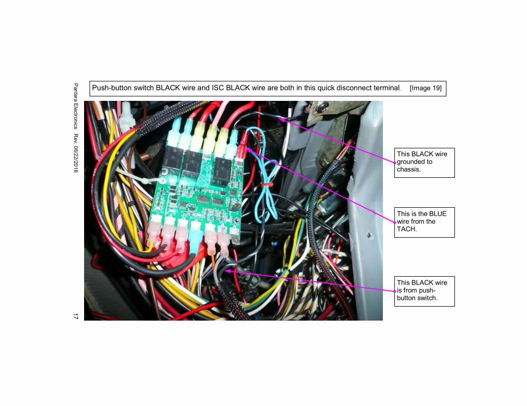
Push-button switch BLACK wire and ISC BLACK wire are both in this quick disconnect terminal. [Image 19]
This BLACK wire is from push-button switch.
This BLACK wire grounded to chassis.
This is the BLUE wire from the TACH.
18
Pan
tera
Ele
ctr
on
ics R
ev.
06/2
2/2
018
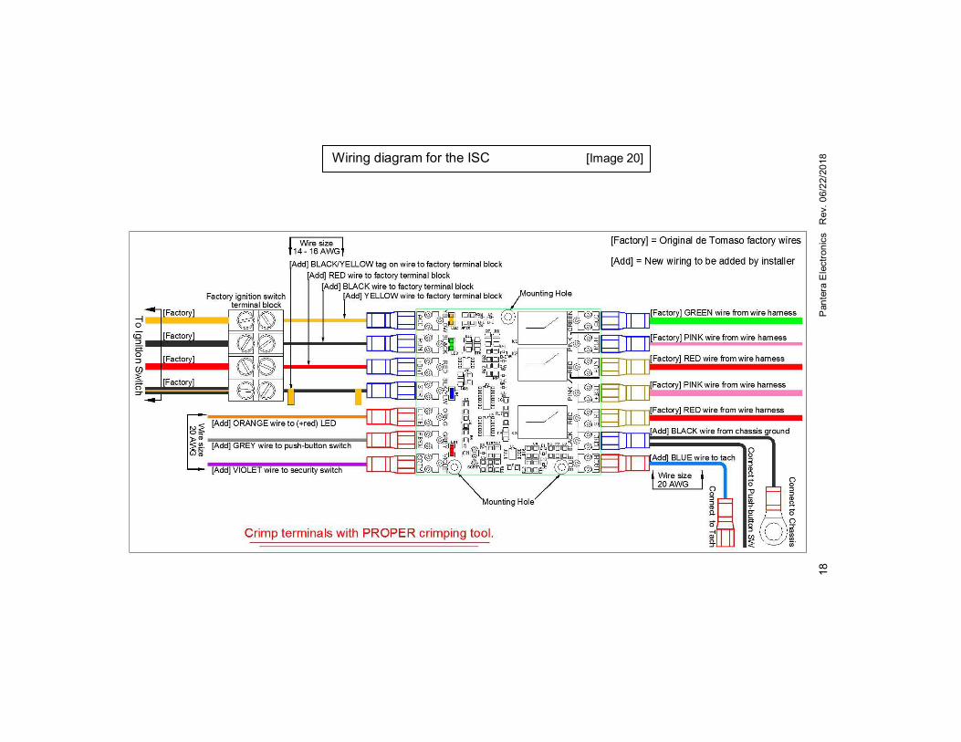
Wiring diagram for the ISC [Image 20]
19 Pantera Electronics Rev. 06/22/2018
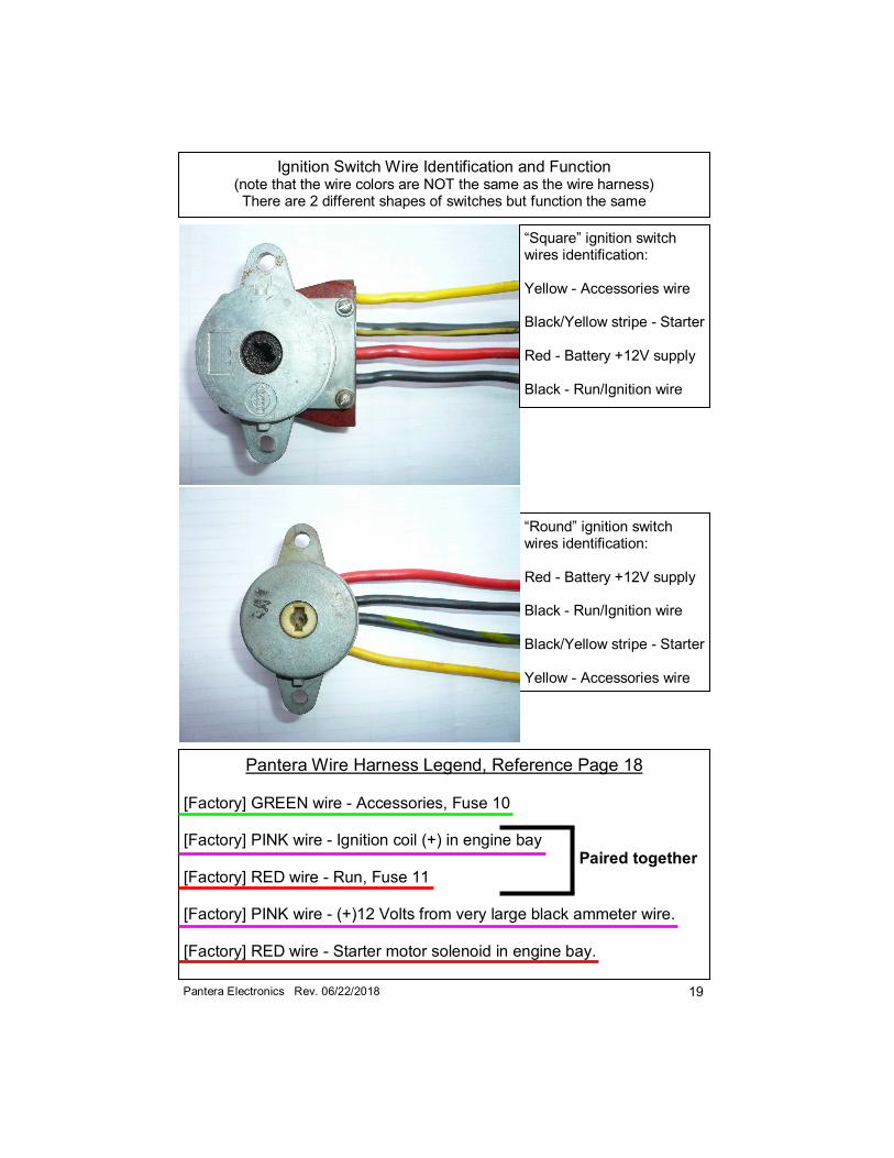
Pantera Wire Harness Legend, Reference Page 18 [Factory] GREEN wire - Accessories, Fuse 10 [Factory] PINK wire - Ignition coil (+) in engine bay Paired together
[Factory] RED wire - Run, Fuse 11 [Factory] PINK wire - (+)12 Volts from very large black ammeter wire. [Factory] RED wire - Starter motor solenoid in engine bay.
“Square” ignition switch wires identification: Yellow - Accessories wire Black/Yellow stripe - Starter Red - Battery +12V supply Black - Run/Ignition wire
Ignition Switch Wire Identification and Function (note that the wire colors are NOT the same as the wire harness) There are 2 different shapes of switches but function the same
“Round” ignition switch wires identification: Red - Battery +12V supply Black - Run/Ignition wire Black/Yellow stripe - Starter Yellow - Accessories wire
20 Pantera Electronics Rev. 06/22/2018
Slide switch in the “OFF” position. Security Switch will NOT operate. Image 22
Use a pin or straighten paper clip to slide the switch to “ON” (up). Slide switch in the “ON” position. Security Switch will operate. Image 23