Embed Size (px)
Citation preview
1 Pantera Electronics Rev. 2/04/2020
Pantera Electronics Electric Parking Brake Controller Push-Button Type Installation Manual
Electric Parking Brake Controller Features and Operation > Designed to operate a pair of Tesla / Brembo calipers through the factory caliper connector. > One switch with normally open contacts is required, press once to “SET” and press again to “RELEASE” the electric parking brake. > Electric parking brake controller and one normally open switch is all that is required for controlling (1) pair of Tesla/Brembo electric parking brake calipers. > Independent monitor and control for left and right calipers with connections for green LED indicator for “Release” and red LED indicator for “Set” parking brake. > Automatically compensates for brake pad wear. > Simple installation with Pantera Electronics installation kit which includes mating connectors, terminals for the calipers and 25 feet of 4 wire cable. >Optional push button with internal LED indicator, RED for “SET” and GREEN for “RELEASE”. > Internal indicators for proper installation or verification of each caliper operation.
Yellow indicator for push-button actuation.
Green indicator for power.
Blue indicator flashes for left caliper functioning.
Orange indicator flashes for right caliper functioning.
2 Pantera Electronics Rev. 2/04/2020
DO NOT APPLY ELECTRIC PARKING BRAKE WHILE CAR IS IN MOTION IN EXCESS OF 10 MILES PER HOUR.
Disclaimer The products from Pantera Electronics have been design and manufactured with the best quality components known to the engineer. The installation instructions have been written to assist the owner in the proper use and installation of the products. Pantera Electronics can not be held responsible or held liable for the interpretation or incorrect implementation of the products.
NOTE: It’s important to keep this installation manual for future reference
since revisions to this product change the contents of the installation manual.
Disconnect the Battery by removing the negative (-) or ground cable from the battery terminal before connecting the Electric Parking Brake Controller.
THERE ARE NO INTERLOCKS TO PREVENT APPLYING THIS PARKING BRAKE SWITCH AT ANYTIME.
NOTE - THE ELECTRIC PARKING BRAKE CONTROLLER MAY CLOSE BOTH CALIPERS THE FIRST TIME IT IS POWERED.
DO NOT ALLOW ANYTHING TO BE BETWEEN THE ROTORS AND CALIPER PADS THE FIRST TIME POWER IS APPLIED,
INCLUDING FINGERS !
READ THIS MANUAL THOROUGHLY BEFORE STARTING THE INSTALLATION, IF YOU DO NOT UNDERSTAND THE CONTENT
THAN HAVE SOMEONE ELSE READ IT TO YOU.
IF YOU DIDN’T FINISH AT LEAST HIGH SCHOOL THEN DON’T ATTEMPT THIS INSTALLATION.
3 Pantera Electronics Rev. 2/04/2020
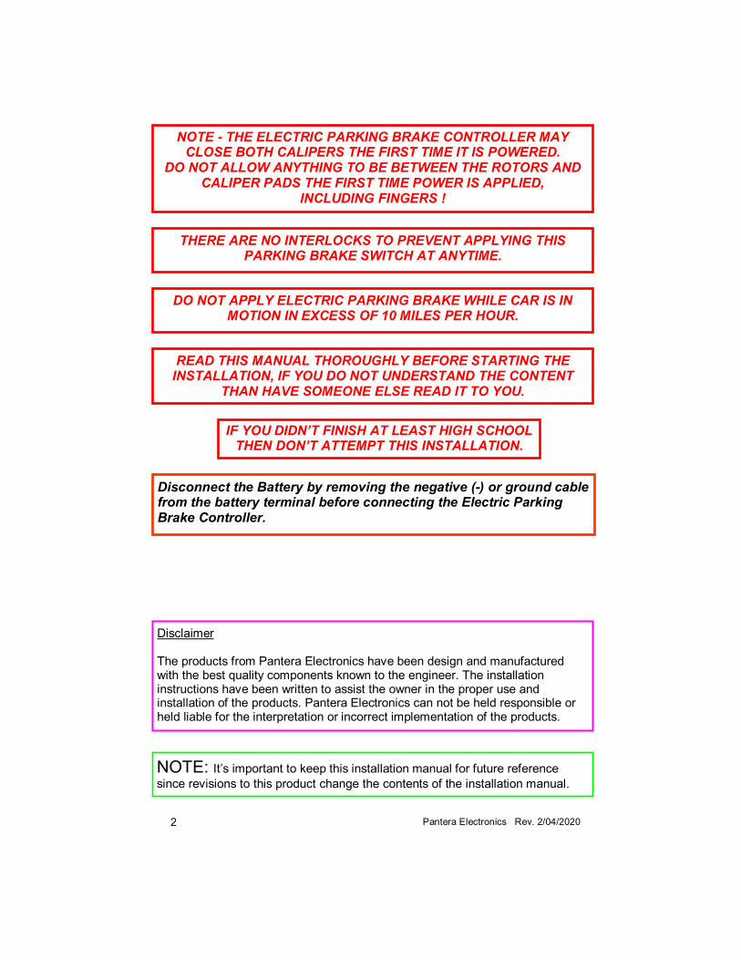
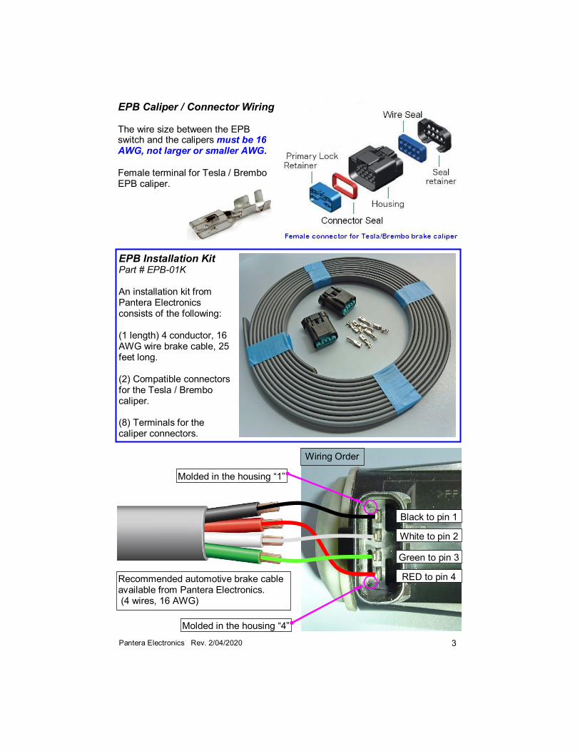
EPB Caliper / Connector Wiring The wire size between the EPB switch and the calipers must be 16 AWG, not larger or smaller AWG. Female terminal for Tesla / Brembo EPB caliper.
EPB Installation Kit Part # EPB-01K An installation kit from Pantera Electronics consists of the following: (1 length) 4 conductor, 16 AWG wire brake cable, 25 feet long. (2) Compatible connectors for the Tesla / Brembo caliper. (8) Terminals for the caliper connectors.
Recommended automotive brake cable available from Pantera Electronics. (4 wires, 16 AWG)
RED to pin 4
Black to pin 1
White to pin 2
Green to pin 3
Wiring Order
Molded in the housing “1”
Molded in the housing “4”
4 Pantera Electronics Rev. 2/04/2020
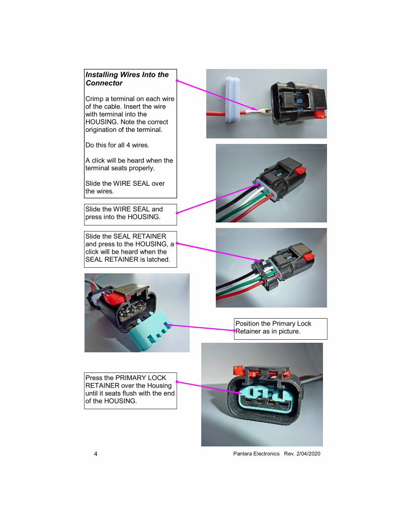
Installing Wires Into the Connector Crimp a terminal on each wire of the cable. Insert the wire with terminal into the HOUSING. Note the correct origination of the terminal. Do this for all 4 wires. A click will be heard when the terminal seats properly. Slide the WIRE SEAL over the wires.
Slide the WIRE SEAL and press into the HOUSING.
Slide the SEAL RETAINER and press to the HOUSING, a click will be heard when the SEAL RETAINER is latched.
Position the Primary Lock Retainer as in picture.
Press the PRIMARY LOCK RETAINER over the Housing until it seats flush with the end of the HOUSING.
5 Pantera Electronics Rev. 2/04/2020
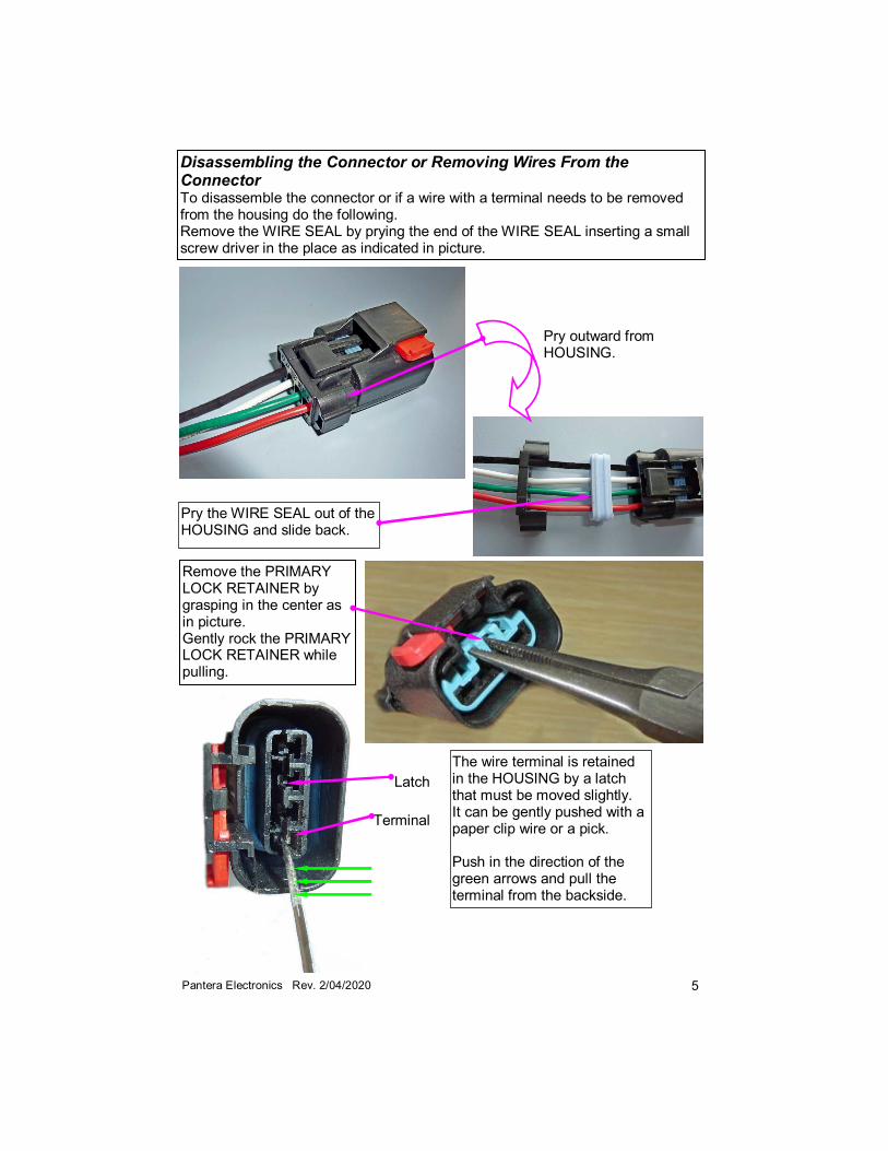
Disassembling the Connector or Removing Wires From the Connector To disassemble the connector or if a wire with a terminal needs to be removed from the housing do the following. Remove the WIRE SEAL by prying the end of the WIRE SEAL inserting a small screw driver in the place as indicated in picture.
The wire terminal is retained in the HOUSING by a latch that must be moved slightly. It can be gently pushed with a paper clip wire or a pick. Push in the direction of the green arrows and pull the terminal from the backside.
Pry the WIRE SEAL out of the HOUSING and slide back.
Remove the PRIMARY LOCK RETAINER by grasping in the center as in picture. Gently rock the PRIMARY LOCK RETAINER while pulling.
Pry outward from HOUSING.
Terminal
Latch
6 Pantera Electronics Rev. 2/04/2020
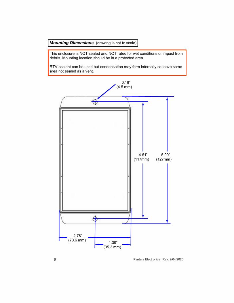
Mounting Dimensions (drawing is not to scale)
4.61” (117mm)
5.00” (127mm)
2.78” (70.6 mm)
1.39” (35.3 mm)
0.18” (4.5 mm)
This enclosure is NOT sealed and NOT rated for wet conditions or impact from debris. Mounting location should be in a protected area. RTV sealant can be used but condensation may form internally so leave some area not sealed as a vent.
7 Pantera Electronics Rev. 2/04/2020
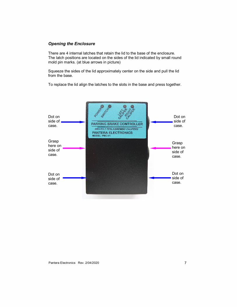
Opening the Enclosure There are 4 internal latches that retain the lid to the base of the enclosure. The latch positions are located on the sides of the lid indicated by small round mold pin marks. (at blue arrows in picture) Squeeze the sides of the lid approximately center on the side and pull the lid from the base. To replace the lid align the latches to the slots in the base and press together.
Dot on side of case.
Grasp here on side of case.
Grasp here on side of case.
Dot on side of case.
Dot on side of case.
Dot on side of case.
8 Pantera Electronics Rev. 2/04/2020
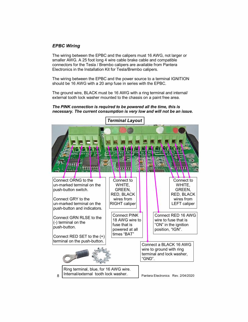
Connect PINK 18 AWG wire to fuse that is powered at all times “BAT”
Connect RED 16 AWG wire to fuse that is “ON” in the ignition position, “IGN”.
Connect a BLACK 16 AWG wire to ground with ring terminal and lock washer, “GND”.
EPBC Wiring The wiring between the EPBC and the calipers must 16 AWG, not larger or smaller AWG. A 25 foot long 4 wire cable brake cable and compatible connectors for the Tesla / Brembo calipers are available from Pantera Electronics in the Installation Kit for Tesla/Brembo calipers. The wiring between the EPBC and the power source to a terminal IGNITION should be 16 AWG with a 20 amp fuse in series with the EPBC. The ground wire, BLACK must be 16 AWG with a ring terminal and internal/external tooth lock washer mounted to the chassis on a paint free area. The PINK connection is required to be powered all the time, this is necessary. The current consumption is very low and will not be an issue.
Terminal Layout
Connect to WHITE, GREEN,
RED, BLACK wires from
RIGHT caliper
Connect to WHITE, GREEN,
RED, BLACK wires from
LEFT caliper
Connect ORNG to the un-marked terminal on the push-button switch. Connect GRY to the un-marked terminal on the push-button and indicators. Connect GRN RLSE to the (-) terminal on the push-button. Connect RED SET to the (+) terminal on the push-button.
Ring terminal, blue, for 16 AWG wire. Internal/external tooth lock washer.
9 Pantera Electronics Rev. 2/04/2020
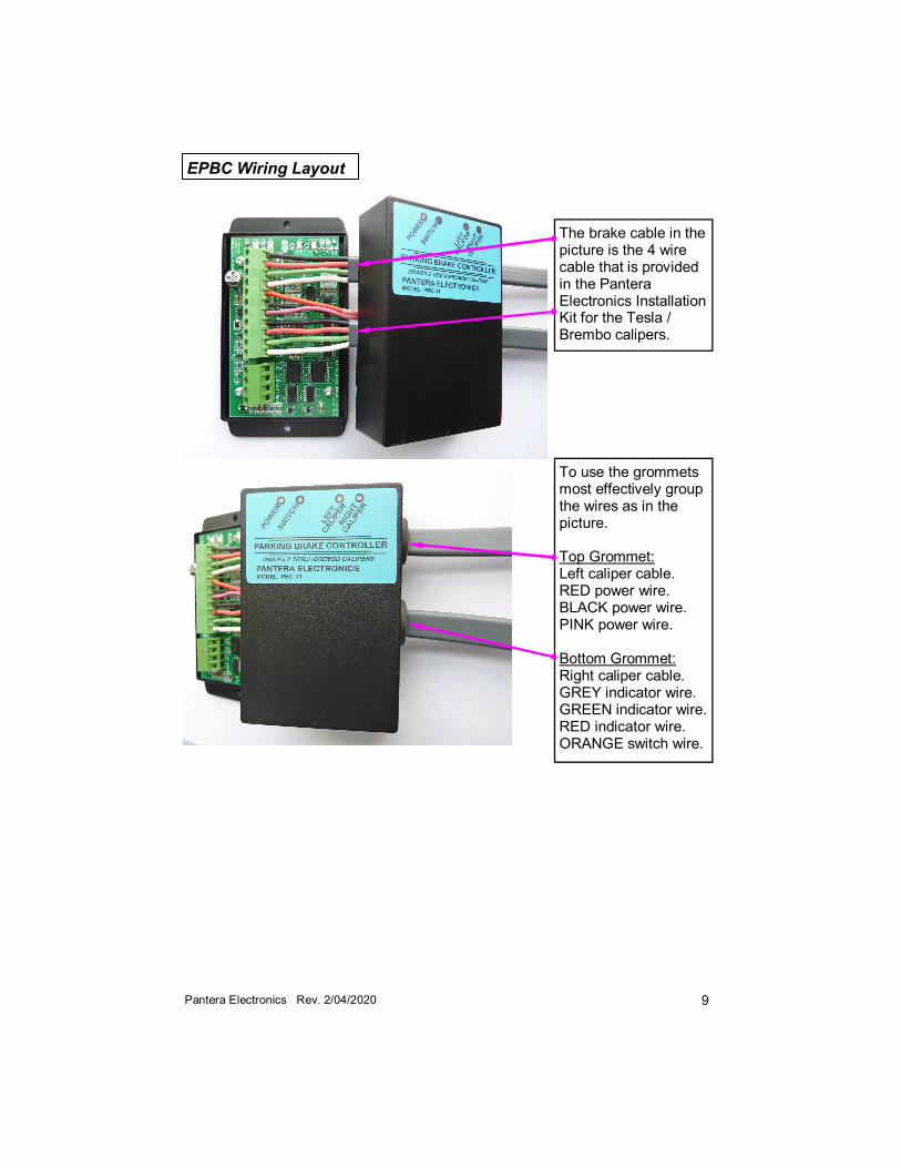
EPBC Wiring Layout
The brake cable in the picture is the 4 wire cable that is provided in the Pantera Electronics Installation Kit for the Tesla / Brembo calipers.
To use the grommets most effectively group the wires as in the picture. Top Grommet: Left caliper cable. RED power wire. BLACK power wire. PINK power wire. Bottom Grommet: Right caliper cable. GREY indicator wire. GREEN indicator wire. RED indicator wire. ORANGE switch wire.
10 Pantera Electronics Rev. 2/04/2020
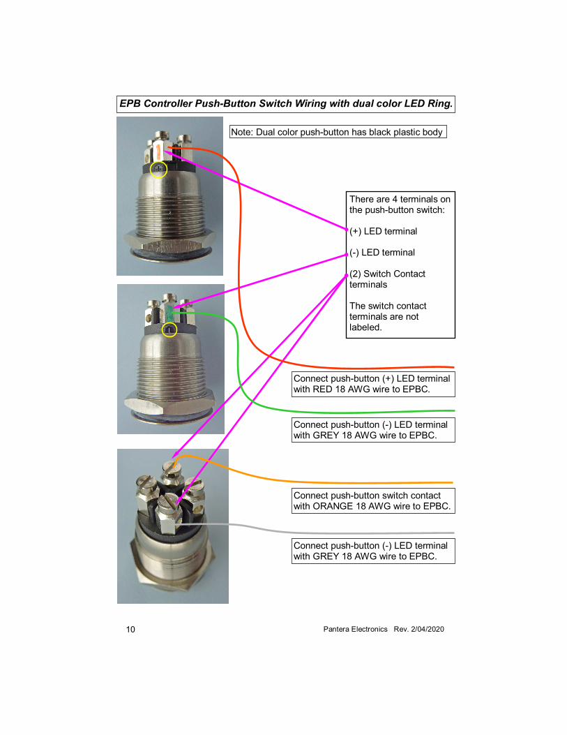
EPB Controller Push-Button Switch Wiring with dual color LED Ring.
There are 4 terminals on the push-button switch: (+) LED terminal (-) LED terminal (2) Switch Contact terminals The switch contact terminals are not labeled.
Connect push-button (-) LED terminal with GREY 18 AWG wire to EPBC.
Connect push-button switch contact with ORANGE 18 AWG wire to EPBC.
Connect push-button (+) LED terminal with RED 18 AWG wire to EPBC.
Connect push-button (-) LED terminal with GREY 18 AWG wire to EPBC.
Note: Dual color push-button has black plastic body
11 Pantera Electronics Rev. 2/04/2020
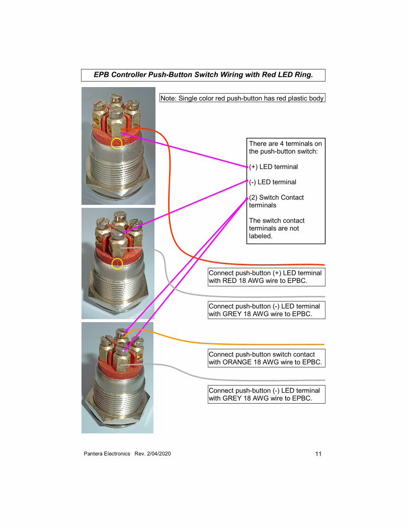
EPB Controller Push-Button Switch Wiring with Red LED Ring.
There are 4 terminals on the push-button switch: (+) LED terminal (-) LED terminal (2) Switch Contact terminals The switch contact terminals are not labeled.
Connect push-button (-) LED terminal with GREY 18 AWG wire to EPBC.
Connect push-button switch contact with ORANGE 18 AWG wire to EPBC.
Connect push-button (+) LED terminal with RED 18 AWG wire to EPBC.
Connect push-button (-) LED terminal with GREY 18 AWG wire to EPBC.
Note: Single color red push-button has red plastic body
12 Pantera Electronics Rev. 2/04/2020
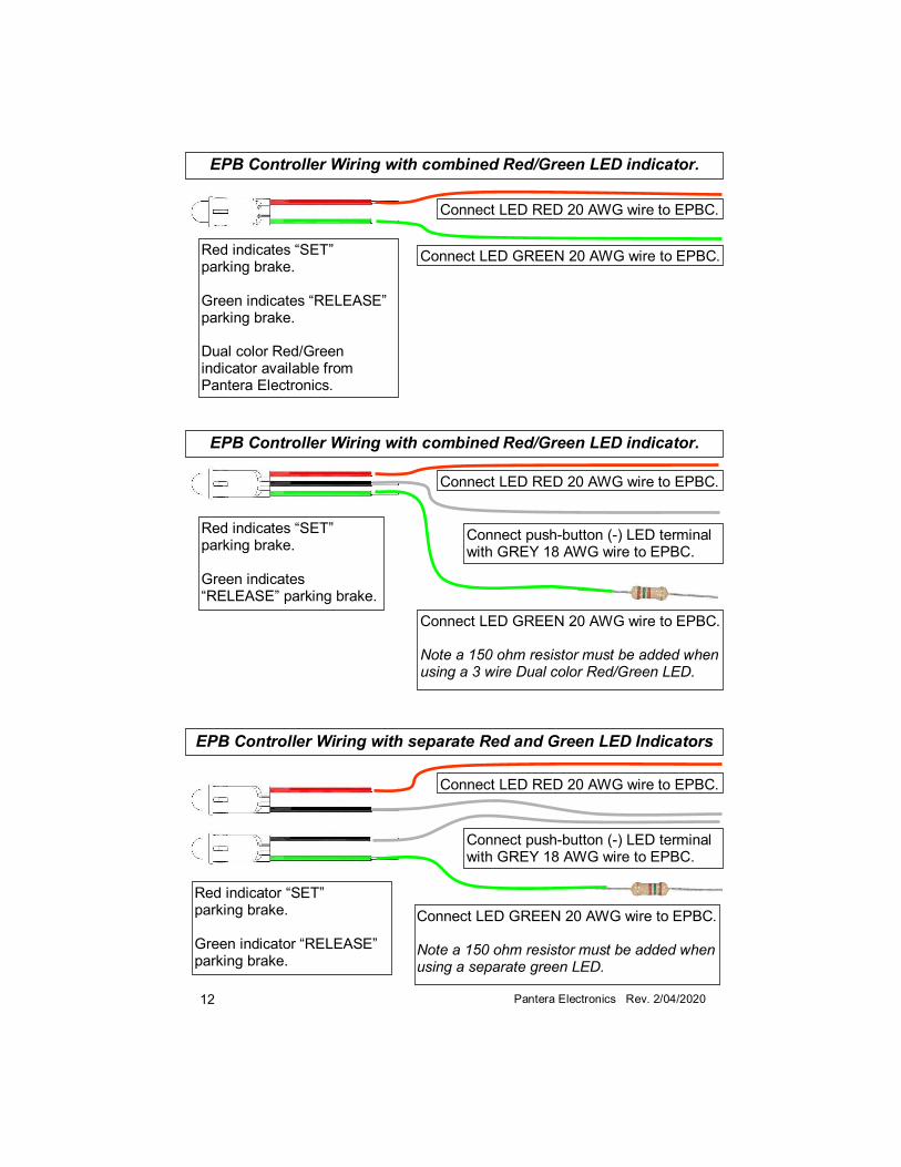
EPB Controller Wiring with combined Red/Green LED indicator.
Connect LED GREEN 20 AWG wire to EPBC.
Connect LED RED 20 AWG wire to EPBC.
Red indicates “SET” parking brake. Green indicates “RELEASE” parking brake. Dual color Red/Green indicator available from Pantera Electronics.
Connect LED GREEN 20 AWG wire to EPBC. Note a 150 ohm resistor must be added when using a separate green LED.
Connect LED RED 20 AWG wire to EPBC.
Red indicator “SET” parking brake. Green indicator “RELEASE” parking brake.
EPB Controller Wiring with separate Red and Green LED Indicators
Connect LED RED 20 AWG wire to EPBC.
Red indicates “SET” parking brake. Green indicates “RELEASE” parking brake.
Connect LED GREEN 20 AWG wire to EPBC. Note a 150 ohm resistor must be added when using a 3 wire Dual color Red/Green LED.
EPB Controller Wiring with combined Red/Green LED indicator.
Connect push-button (-) LED terminal with GREY 18 AWG wire to EPBC.
Connect push-button (-) LED terminal with GREY 18 AWG wire to EPBC.
13 Pantera Electronics Rev. 2/04/2020
EPBC Testing The calipers MUST be installed and disk rotor in place BEFORE testing the EPBC. 1. Re-connect battery negative (-) or ground cable from the battery terminal. 2. When the EPBC is first powered the indicators may be illuminated randomly, this will self-correct after the EPBC is cycled. 3. The BLUE internal indicator is for the left caliper and an ORANGE internal indicator is for the right caliper. These indicators should flash when the caliper is moving. 4. Press the push button switch, the YELLOW internal indicator should flash once per push-button press. This verifies proper wiring to the push-button switch. 5. Press the push button switch this should cause both calipers to move clamping the disk. When the brake pads contact the disk the motor will continue to operate until pressure is developed. Verify that both blue and orange indicators flash until the caliper stops, this verifies both calipers are wired properly. 6. Press the push button switch again this should cause both calipers to move away from the disk. The caliper will open a preset distance that should be enough to allow the disk to rotate freely. Verify that both blue and orange indicators flash until the caliper stops, this verifies both calipers are functioning properly. The RED indicator in the push-button switch will illuminate when both calipers are “SET”. 7. Press the push button switch again this should cause both calipers to close or “SET” and the RED indicator to illuminate then the calipers have clamped the disk at the preset pressure. 8. Try to move the car by manual pushing or using the engine and first gear to over-come the EPBC. If resistance is felt then the EPBC is functioning properly. 9. Press the push button switch again this should cause both calipers to move away from the disk. 10. Try to move the car by manual pushing or using the engine and first gear to over-come the EPBC. If resistance is no longer felt then the EPBC is functioning properly. 11. Testing complete.
14 Pantera Electronics Rev. 2/04/2020
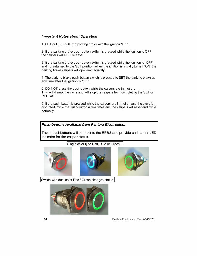
Push-buttons Available from Pantera Electronics. These pushbuttons will connect to the EPBS and provide an internal LED indicator for the caliper status.
Single color type Red, Blue or Green
Switch with dual color Red / Green changes status
Important Notes about Operation 1. SET or RELEASE the parking brake with the ignition “ON”. 2. If the parking brake push-button switch is pressed while the ignition is OFF the calipers will NOT release. 3. If the parking brake push-button switch is pressed while the ignition is “OFF” and not returned to the SET position, when the ignition is initially turned “ON” the parking brake calipers will open immediately. 4. The parking brake push-button switch is pressed to SET the parking brake at any time after the ignition is “ON”. 5. DO NOT press the push-button while the calpers are in motion. This will disrupt the cycle and will stop the calipers from completing the SET or RELEASE. 6. If the push-button is pressed while the calpers are in motion and the cycle is disrupted, cycle the push-button a few times and the calipers will reset and cycle normally.
15 Pantera Electronics Rev. 2/04/2020
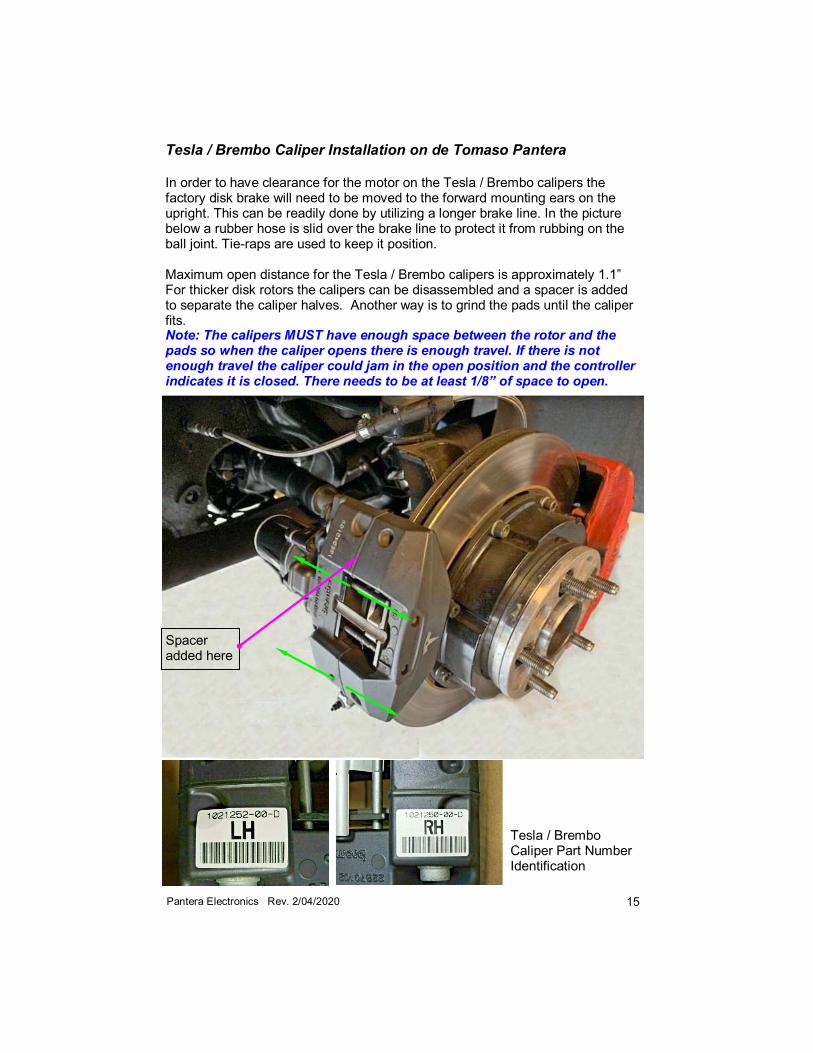
Tesla / Brembo Caliper Part Number Identification
Tesla / Brembo Caliper Installation on de Tomaso Pantera
In order to have clearance for the motor on the Tesla / Brembo calipers the factory disk brake will need to be moved to the forward mounting ears on the upright. This can be readily done by utilizing a longer brake line. In the picture below a rubber hose is slid over the brake line to protect it from rubbing on the ball joint. Tie-raps are used to keep it position. Maximum open distance for the Tesla / Brembo calipers is approximately 1.1” For thicker disk rotors the calipers can be disassembled and a spacer is added to separate the caliper halves. Another way is to grind the pads until the caliper fits. Note: The calipers MUST have enough space between the rotor and the pads so when the caliper opens there is enough travel. If there is not enough travel the caliper could jam in the open position and the controller indicates it is closed. There needs to be at least 1/8” of space to open.
Spacer added here
16 Pantera Electronics Rev. 2/04/2020
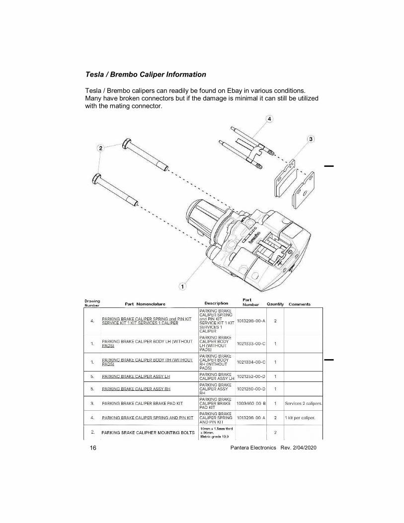
Tesla / Brembo Caliper Information
Tesla / Brembo calipers can readily be found on Ebay in various conditions. Many have broken connectors but if the damage is minimal it can still be utilized with the mating connector.