Embed Size (px)
Citation preview
palmOTDR
User’s Manual
Shineway Technologies, Inc.
All rights reserved.

palmOTDR
User’s Manual for palmOTDR
Shineway Technologies, Inc. - i -
Notices
Copyright© 2014, ShinewayTech, All rights reserved.
No part of this manual may be reproduced in any form or by any means (including
electronic storage and retrieval or translation into a foreign language) without prior
agreement and written consent from ShinewayTech as governed by international
copyright laws.
Warranty
The material contained in this document is subject to change without notice.
ShinewayTech makes no warranty of any kind with regard to this material, including, but
not limited to, the implied warranties of merchantability and fitness for a particular purpose.
ShinewayTech shall not be liable for errors contained herein or for incidental or
consequential damages in connection with furnishing, performance, or use of this material.
The battery is a consumable part and is not subject to the palmOTDR warranty.
ISO9001 Certification
Produced to ISO9001 International Quality System Standard as part of ShinewayTech,
objective of continually increasing customer satisfaction through improved process control.
User’s Manual for palmOTDR
Shineway Technologies, Inc. - ii -
Safety Instructions
During each stage of operation of this instrument, please always observe the following
safety instructions. Not taking any safety precautions or following the instructions will
violate the safety standards of design, manufacturing and application of these instruments. In
no case will Shineway Technologies bear the responsibilities for consequences incurred by
violation of the following instructions.
GENERAL
This product is a Safety Class 1 instrument. The protective features of this product may be
impaired if it is used in a manner not specified in the operation instrument.
Environmental conditions
It is designed to operate at a maximum relative humidity of 95% and at altitudes of up to
2000 meters. Refer to the specifications tables.
Before applying power
Verify that the product is set to match the available line voltage, the correct fuse is installed,
and all safety precautions are taken. Note the instrument’s external markings described
under Symbols.
Do not operate in an explosive atmosphere
Do not operate the instrument in the presence of flammable gases or fumes.
Do not remove the instrument cover
Operating personnel must not remove instrument covers. Component replacement and
internal adjustments must be made only by qualified service personnel.
Instrument that appears damaged or defective should be made inoperative and secured
against unintended operation until they can be repaired by qualified service personnel.
User’s Manual for palmOTDR
Shineway Technologies, Inc. - iii -
Safety Terms Used in This Manual
The WARNING sign denotes a hazard. It calls attention to a
procedure, practice, or the like, which, if not correctly performed or
adhered to, could result in personnel injury. Do not proceed beyond a
WARNING sign until the indicated conditions are fully understood
and met.
The CAUTION sign denotes a hazard. It calls attention to an
operating procedure, or the like, which, if not correctly performed or
adhered to, could result in damage to or destruction of part or the
entire product. Do not proceed beyond a CAUTION sign until the
indicated conditions are fully understood and met.
The NOTE sign information that may be beneficial during the use
and maintenance of the instrument.
palmOTDR is a laser instrument. Users should avoid looking directly into the
optic output. And the use of microscope or magnifier should also be avoided, for
the use of such devices can focus a highly intense beam onto the retina, which
may result in permanent eye damage
Make sure that the optical fiber or cable is not in use and there is no laser beam
in the fiber before testing via palmOTDR. Otherwise, it may result in imprecise
test trace, even permanent damage for the palmOTDR
Battery: Battery for this instrument is rechargeable NiMH battery. If unused for a long
time, battery should be recharged before being used. If the instrument is left idle for more
than two months, it should be recharged to maintain adequate battery volume. Do not
recharge batteries for more than 8 hours. Do not take batteries out without technical staff’s
help. Do not expose batteries to fire or intense heat. Do not open or mutilate batteries. Avoid
User’s Manual for palmOTDR
Shineway Technologies, Inc. - iv -
touching the electrolyte in the batteries, which is corrosive and may cause injuries to eyes,
skin or damage to clothes. For battery protection and performance.
External Power: palmOTDR from ShinewayTech supports external power. Power
requirements: DC 13.8V/1.2A.
Laser Radiation: To avoid serious eye injury, never look directly into the optical outputs
of fiber optic network equipment, test equipment, patch cords, or test jumpers.
Always avoid looking directly into the optical output port, when the instrument
is working
Always replace protective dust cap on the detector port when the instrument is
not being used
Always avoid looking directly at unconnected end of optic fiber in testing and
make the unconnected end pointing at a non-reflective object, if possible
User’s Manual for palmOTDR
Shineway Technologies, Inc. - v -
Table of Contents
Notices .................................................................................................................................... i
Warranty ................................................................................................................................ i
Safety Instructions ................................................................................................................ ii
1.General Information ......................................................................................................... 1
1.1 Scope of this Manual .................................................................................................... 1
1.2 Unpacking and Inspection ............................................................................................ 1
1.3 Introduction .................................................................................................................. 1
2. Basic Operation ................................................................................................................ 4
2.1 Foreword ...................................................................................................................... 4
2.2 Instrument Interfaces Instructions ................................................................................ 4
2.3 Use of Batteries ............................................................................................................ 5
2.4 Keypad Functions ......................................................................................................... 6
3.Basic Information of palmOTDR ..................................................................................... 7
3.1 Principle of palmOTDR ............................................................................................... 7
3.2 Basic Definition and Classification of Events .............................................................. 7
3.2.1 Events ................................................................................................................. 7
3.2.1.1 Reflection Events ........................................................................................ 8
3.2.1.2 Non-reflection Events ................................................................................. 8
3.2.1.3 Inspection Events ........................................................................................ 8
3.3 Measurement Application of palmOTDR ..................................................................... 9
3.3.1 Measurement Contents of palmOTDR ............................................................... 9
3.3.2 Trace Analysis of palmOTDR ............................................................................ 9
3.4 Trace Display Screen of palmOTDR .......................................................................... 10
3.4.1 Trace Display of palmOTDR ........................................................................... 10
3.4.2 Information Window of palmOTDR ................................................................ 10
3.4.2.1 Measurement Trace Parameters ................................................................ 10
3.4.2.2 Events List ................................................................................................. 11
3.4.2.3 Information of Marker A/B ....................................................................... 12
3.4.2.4 Information of Fiber .................................................................................. 13
3.4.3 Menu Bar and Window of palmOTDR ............................................................ 13
3.4.3.1 Menu Bar and Icons of palmOTDR .......................................................... 13
3.4.3.2 Parameter Configuration on palmOTDR Menu Bar ................................. 14
3.4.3.2.1 Definitions of Measurement Parameters ............................................ 15
3.4.3.2.2 Range Configuration .......................................................................... 15
3.4.3.2.3 Pulse Width Configuration ................................................................. 16
3.4.3.2.4 Average Time Configuration .............................................................. 17
3.4.3.2.5 Wavelength Configuration .................................................................. 17
User’s Manual for palmOTDR
Shineway Technologies, Inc. - vi -
3.4.3.2.6 Measurement Mode Configuration..................................................... 18
3.4.3.2.7 Power Meter and Laser Source Configuration (Optional only) .......... 18
3.4.3.2.8 Length Units Configuration ................................................................ 19
3.4.3.2.9 IOR Configuration .............................................................................. 20
3.4.3.2.10 Scatter Coefficient Configuration ..................................................... 20
3.4.3.2.11 Non Reflection Threshold Configuration ......................................... 21
3.4.3.2.12 Reflection Threshold Configuration ................................................. 22
3.4.3.2.13 End Threshold Configuration ........................................................... 22
3.4.3.2.14 Delete File ........................................................................................ 23
3.4.3.2.15 Time Configuration .......................................................................... 24
3.4.3.2.16 Auto off Configuration ..................................................................... 24
3.4.3.2.17 Language Configuration ................................................................... 25
3.4.3.2.18 Contrast Adjustment of LCD Display .............................................. 25
3.4.3.2.19 Color Mode Setting .......................................................................... 25
3.4.3.2.20 Default Set ........................................................................................ 26
3.4.3.2.21 Help .................................................................................................. 26
3.5 Battery Recharge Status .............................................................................................. 28
4. Trace Measurement and Processing of Existing Traces .............................................. 29
4.1 Instructions on GUI .................................................................................................... 29
4.2 Trace Measurement of palmOTDR ............................................................................ 30
4.2.1 Trace Measurement- Connect Optical Fiber..................................................... 30
4.2.2 Trace Measurement - Parameter Configuration ............................................... 30
4.2.3 Trace Measurement- Auto ................................................................................ 30
4.2.4 Trace Measurement - Manual ........................................................................... 32
4.2.5 Trace Measurement -Reasons of Measurement Failures .................................. 32
4.3 Information Window .................................................................................................. 32
4.3.1 Switch between Information Window Items .................................................... 33
4.3.2 Review Event List ............................................................................................ 33
4.3.3 Review Marker A/B Information ..................................................................... 33
4.3.3.1 Switching between Marker A/B ................................................................. 33
4.3.3.2 Information between Marker A/B ............................................................. 33
4.4 Zoom in Trace Horizontally ....................................................................................... 33
4.5 Zoom out Trace Horizontally ..................................................................................... 34
4.6 Zoom in Trace Vertically ............................................................................................ 34
4.7 Zoom out Trace Vertically .......................................................................................... 34
4.8 Re-analyze the trace ................................................................................................... 34
4.9 Save Trace .................................................................................................................. 35
4.10 Browse Saved Traces ................................................................................................ 35
4.11 Upload Saved Traces ................................................................................................ 36
4.12 Alter Measurement Parameters in Realtime Testing ................................................. 38
4.13 Power Meter and Laser Source Settings (Optional) ................................................. 38
User’s Manual for palmOTDR
Shineway Technologies, Inc. - vii -
5. Maintenance and Calibration ........................................................................................ 47
Maintenance and Replacing of Batteries .......................................................................... 47
Cleaning of Interfaces....................................................................................................... 48
Effects of Cleaning Interfaces and Connectors ............................................. 48
Safety instructions to be followed before cleaning ....................................... 48
Tools for Cleaning Interfaces and Connectors .............................................. 48
Preferred Procedure for Cleaning Interfaces and Connectors ....................... 49
Calibration Requirements ................................................................................................. 49
6. Warranty Information ................................................................................................... 50
Terms of Warranty ............................................................................................................ 50
Exclusions ........................................................................................................................ 50
Warranty Registration ....................................................................................................... 50
Returning Instruments ...................................................................................................... 50
Contacting Customer Service ........................................................................................... 51
User’s Manual for palmOTDR
Shineway Technologies, Inc. - viii -
Table of Figure
Figure 2-1. Coping of palmOTDR .......................................................................................... 4
Figure 2-2. Operation Interface of palmOTDR ....................................................................... 6
Figure 3-1. Reflection Event ................................................................................................... 8
Figure 3-2. Non-reflection Event ............................................................................................ 8
Figure 3-3. Trace Display Screen .......................................................................................... 10
Figure 3-4. Traces and Coordinates ....................................................................................... 10
Figure 3-5.(a) Measurement Trace Parameters ...................................................................... 11
Figure 3-5.(b) Analysis Trace Parameters ............................................................................. 11
Figure 3-6. Events List .......................................................................................................... 12
Figure 3-7. Information of Marker A/B ................................................................................. 12
Figure 3-8. Information of Fiber ........................................................................................... 13
Figure 3-9. (a) Parameter Configuration ............................................................................... 14
Figure 3-9. (b) Parameter Configuration ............................................................................... 14
Figure 3-10. Set Range .......................................................................................................... 15
Figure 3-11. Pulse Width Configuration ................................................................................ 16
Figure 3-12. Average Time Configuration ............................................................................. 17
Figure 3-13. Wavelength Configuration ................................................................................ 18
Figure 3-14. Measurement Mode Configuration ................................................................... 18
Figure 3-15. VFL Configuration ............................................................................................ 19
Figure 3-16. Length Units Configuration .............................................................................. 20
Figure 3-17. IOR Configuration ............................................................................................ 20
Figure 3-18. Scatter Coefficient Configuration ..................................................................... 21
Figure 3-19. Non Reflection Threshold Configuration ......................................................... 21
Figure 3-20. Reflection Threshold Configuration ................................................................. 22
Figure 3-21. End Threshold Configuration ........................................................................... 23
Figure 3-22. Delete File ......................................................................................................... 23
Figure 3-23. Time Configuration ........................................................................................... 24
Figure 3-24. Auto Off Configuration ..................................................................................... 24
Figure 3-25. Language Configuration ................................................................................... 25
Figure 3-26. Contrast Adjustment of LCD Display ............................................................... 25
Figure 3-27. Color Mode Setting ........................................................................................... 26
Figure 3-28. Load Default ..................................................................................................... 26
Figure 3-29. (a) Help ............................................................................................................. 27
Figure 3-29. (b) Help ............................................................................................................. 27
Figure 3-29. (c) Help ............................................................................................................. 27
Figure 4-1. Power on Interface .............................................................................................. 29
Figure 4-2. Quick Reference ................................................................................................. 29
Figure 4-3.(a) Measuring ....................................................................................................... 31
Figure 4-3.(b) Measuring....................................................................................................... 31
Figure 4-4. Trace Measurement of palmOTDR ..................................................................... 32
Figure 4-5. Save Trace ........................................................................................................... 35

User’s Manual for palmOTDR
Shineway Technologies, Inc. - ix -
Figure 4-6. Browse Saved Traces .......................................................................................... 36
Figure 4-7. Upload Saved Traces .......................................................................................... 37
Figure 4-8. Realtime Testing ................................................................................................. 38
Figure 5-1. Replacing Battery ............................................................................................... 47
Figure 5-2. Structure of Flange.............................................................................................. 49
User’s Manual for palmOTDR
Shineway Technologies, Inc. - 1 -
1.General Information
1.1 Scope of this Manual
Thank you for purchasing ShinewayTech instrument. Please read this manual carefully
before using any of ShinewayTech series fiber-optic instrument. Always observe the
warnings and cautions appearing throughout this manual.
This manual contains the information necessary for proper operation and maintenance of
ShinewayTech palmOTDR, troubleshooting instructions as well as information regarding
obtaining services.
All ShinewayTech palmOTDR are carefully assembled and undergo a rigorous
mechanical, electrical, and optical inspection prior to shipment. Beside the instrument, the
package should also include a data transfer cable, a power adapter, a PC Analysis software
installation disk and this users’ manual etc. For detailed information, refer to the packing list
Upon receiving the instrument, please check for any obvious signs of physical damage that
may have occurred during shipment. Report any damage to the shipping agent or the
representative of Shineway Technologies Inc. immediately. Retain the original packing
materials in case reshipment becomes necessary.
1.2 Unpacking and Inspection
This instrument has been carefully packed in accordance with standard shipping procedures.
Examine the instrument for damage that may have occurred during shipment. If you find
any damage or the instrument is not working, or if any of the following items are not
included, please contact your representative of Shineway Technologies, Inc.
If necessary, you may contact Shineway Technologies, Inc via this email:
1.3 Introduction
ShinewayTech palmOTDR are the preferred choice for the measurement of optical
fiber’s specifications. With OTDR, you can make assessment of one single optical fiber or a
whole optical fiber chain. Especially, you can directly observe loss and events distribution of
optical fiber chain.
User’s Manual for palmOTDR
Shineway Technologies, Inc. - 2 -
ShinewayTech palmOTDR check the transmission quality of optic fiber through
measurement of backward scattered lights. Standard organizations like International
Telecom Union (ITU) define backward scattered lights as effective analysis means of
measurement of optical fiber loss. Backward scattering is also the only effective way of
connector inspection, which can be applied to measure the length of optical fiber, too.
Therefore, palmOTDR is a useful tool for optical fiber manufacturing, installation and
maintenance.
palmOTDR works through reviewing “events” in optical fiber (for example, irregularities
and connectors), which is quite helpful for quality control for those who are in charge of
optical fiber manufacturing, installation and maintenance. palmOTDR can help identify the
irregularities in optical fiber, locate them, and measure their attenuation, relevant loss and
their homogeneity.
palmOTDR is more helpful for field operation. It can help to check the qualification of
optical fiber chain circuit on a regular basis. For the purpose of future maintenance,
transmission quality and condition of optical fiber need to be recorded and stored, which
includes measurement of optical path, total loss, and loss of all tie-ins and connectors.
Besides, palmOTDR are easy to use, small and compact. According to the ergonomics, they
are designed to fully embody the user's convenience with its large LCD display and
graphical interface. They can save and transfer the measurement curves data to a PC by the
provided software for further analyzing, reporting and printing.
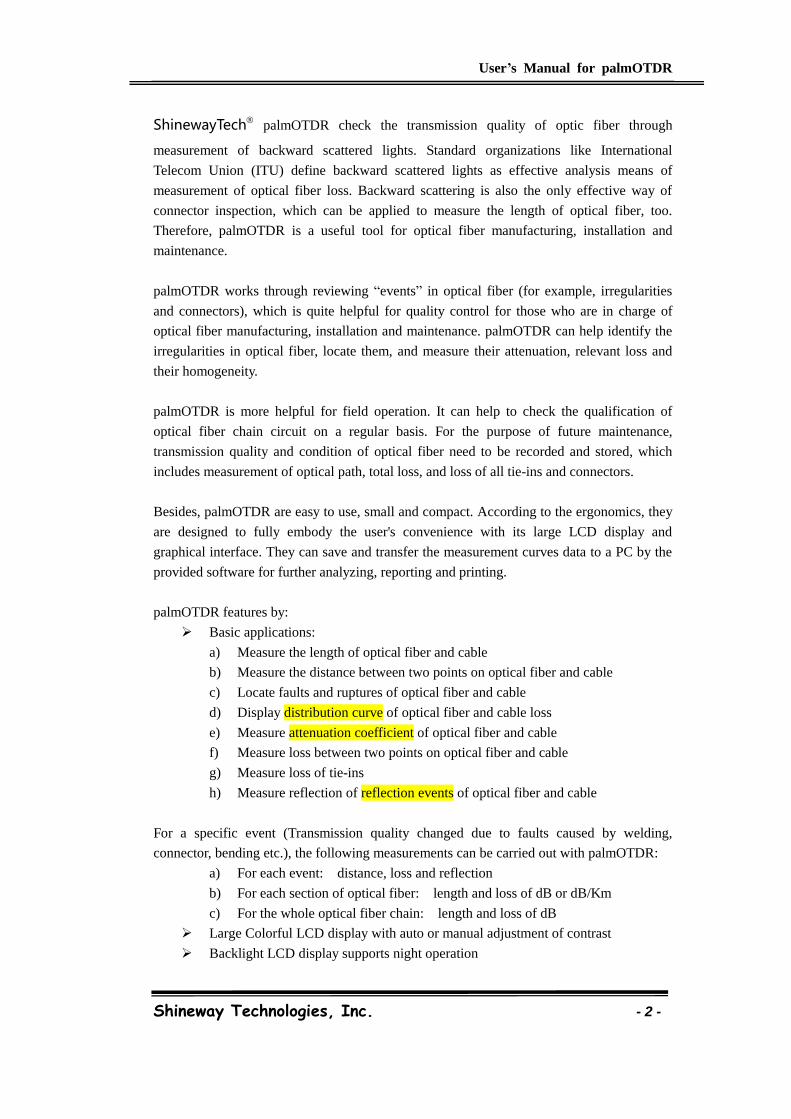
palmOTDR features by:
Basic applications:
a) Measure the length of optical fiber and cable
b) Measure the distance between two points on optical fiber and cable
c) Locate faults and ruptures of optical fiber and cable
d) Display distribution curve of optical fiber and cable loss
e) Measure attenuation coefficient of optical fiber and cable
f) Measure loss between two points on optical fiber and cable
g) Measure loss of tie-ins
h) Measure reflection of reflection events of optical fiber and cable
For a specific event (Transmission quality changed due to faults caused by welding,
connector, bending etc.), the following measurements can be carried out with palmOTDR:
a) For each event: distance, loss and reflection
b) For each section of optical fiber: length and loss of dB or dB/Km
c) For the whole optical fiber chain: length and loss of dB
Large Colorful LCD display with auto or manual adjustment of contrast
Backlight LCD display supports night operation

User’s Manual for palmOTDR
Shineway Technologies, Inc. - 3 -
Easy operation with trace graphic display
Trace storage function
RS232/USB Data upload port
PC analysis software for analyzing and reporting previously stored data
Auto off function conserving battery life
DC/AC power supply
Auto recharging, over 8 hours operation for one charge.
User’s Manual for palmOTDR
Shineway Technologies, Inc. - 4 -
2. Basic Operation
2.1 Foreword
This part introduces the basic operation on the palmOTDR. Specific operations of each type
instrument are elaborated in Chapter 3 of this manual. Please read this manual carefully for
optimal operation. Should you encounter any problems during operation, you are welcome
to contact the technical staff of our company or representatives.
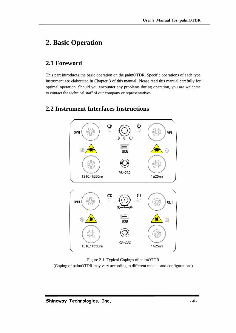
2.2 Instrument Interfaces Instructions
USB
RS-2321310/1550nm 1625nm
OPM VFL
USB
RS-2321310/1550nm 1625nm
ONU OLT
Figure 2-1. Typical Copings of palmOTDR
(Coping of palmOTDR may vary according to different models and configurations)
User’s Manual for palmOTDR
Shineway Technologies, Inc. - 5 -
OTDR/VFL (VFL is is standard on S20BE, S20C/N and S20D/N; optional on
M20AE, S20AE, S20C/P, S20C/X, S20C/E, P11C and P13C)
Fiber optic output for OTDR and VFL, a FC/PC (interchangeable SC, ST)
connector is used for optic interface.
ONU/OLT (Available on P11C and P13C)
Fiber optic ports of PON Power Meter module on palmOTDR-P series.
AC Power Jack
Power adapter jack requirements: 13.8V [email protected].
Data Transfer Port
For all types, there are USB interface and RS232 interface. This interface is used
to transfer saved traces in the instrument to a PC for further analysis by associated
trace manager.
Power/Charge Indicator
When measurement power on or charging, the relevant indicator will be lightened.
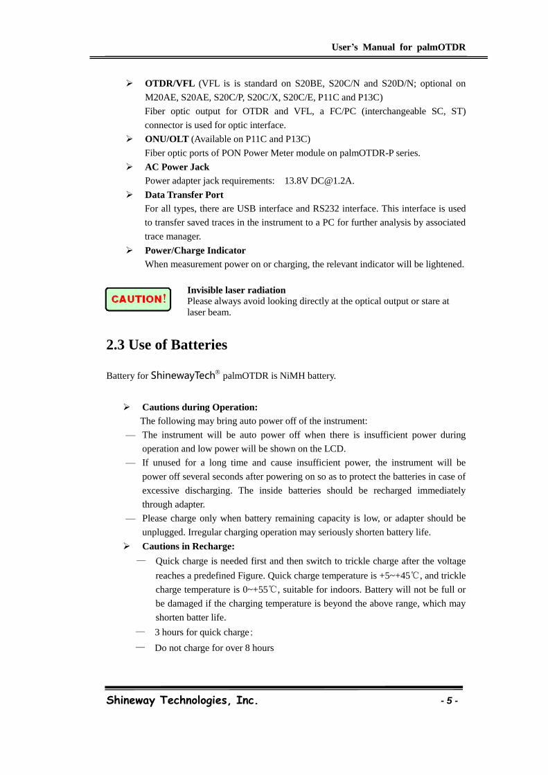
Invisible laser radiation
Please always avoid looking directly at the optical output or stare at
laser beam.
2.3 Use of Batteries
Battery for ShinewayTech palmOTDR is NiMH battery.
Cautions during Operation:
The following may bring auto power off of the instrument:
— The instrument will be auto power off when there is insufficient power during
operation and low power will be shown on the LCD.
— If unused for a long time and cause insufficient power, the instrument will be
power off several seconds after powering on so as to protect the batteries in case of
excessive discharging. The inside batteries should be recharged immediately
through adapter.
— Please charge only when battery remaining capacity is low, or adapter should be
unplugged. Irregular charging operation may seriously shorten battery life.
Cautions in Recharge:
— Quick charge is needed first and then switch to trickle charge after the voltage
reaches a predefined Figure. Quick charge temperature is +5~+45℃, and trickle
charge temperature is 0~+55℃, suitable for indoors. Battery will not be full or
be damaged if the charging temperature is beyond the above range, which may
shorten batter life.
— 3 hours for quick charge;
— Do not charge for over 8 hours
User’s Manual for palmOTDR
Shineway Technologies, Inc. - 6 -
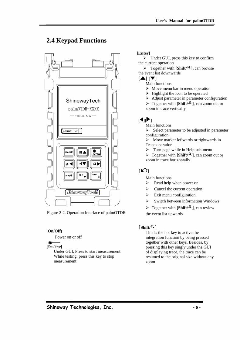
2.4 Keypad Functions
ShinewayTech
palmOTDR-XXXX
--- Version X.X ---
Figure 2-2. Operation Interface of palmOTDR
[On/Off]
Power on or off
[ ] Under GUI, Press to start measurement.
While testing, press this key to stop
measurement
[Enter] Under GUI, press this key to confirm
the current operation
Together with [Shift/ ], can browse
the event list downwards
[ ] [ ] Main functions:
Move menu bar in menu operation
Highlight the icon to be operated
Adjust parameter in parameter configuration
Together with [Shift/ ], can zoom out or
zoom in trace vertically
[ ][ ] Main functions:
Select parameter to be adjusted in parameter
configuration
Move marker leftwards or rightwards in
Trace operation
Turn page while in Help sub-menu
Together with [Shift/ ], can zoom out or
zoom in trace horizontally
[ ]
Main functions:
Read help when power on
Cancel the current operation
Exit menu configuration
Switch between information Windows
Together with [Shift/ ], can review
the event list upwards
[Shift/ ] This is the hot key to active the
integration function by being pressed
together with other keys. Besides, by
pressing this key singly under the GUI
of displaying trace, the trace can be
resumed to the original size without any
zoom
User’s Manual for palmOTDR
Shineway Technologies, Inc. - 7 -
3.Basic Information of palmOTDR
3.1 Principle of palmOTDR
OTDR (Optical Time Domain Reflectometer) is a measurement instrument for identifying
optic fiber transmission features. The instrument is mainly used to measure attenuation of a
whole optic fiber chain and provide attenuation details relating to length, namely detect,
locate and measure any event in optic fiber chain (events refer to faults caused by welding,
connectors, and bending whose transmission change can be measured). Its non-destructive,
one-end connection and rapid measurement have made the palmOTDR an indispensable tool
for manufacture, construction, and maintenance of optic fiber.
The faults and heterogeneity of optic fiber itself cause Rayleigh scattering of light pulse
transmitted in optic fiber. Part of light pulse is scattered in the reverse direction, and this is
called Rayleigh backward scattering, which actually provides attenuation details relating to
length.
Information relating to distance is obtained through time information (that’s the reason why
there is “time Domain” in the name of OTDR). Fresnel reflection occurs at the boundary
between two media of different IOR (for example, connections of faults, connectors, or optic
fiber end). This reflection is used to locate the discontinuous points on optic fiber. The
magnitude of reflection depends on the difference between IOR and the smoothness of
boundary.
OTDR sends out a light pulse into connected optic fiber, and receive reflections of events
and backward scattering power of pulse in time. Locus will be displayed on LCD. The
y-axis is dB value of backward scattering power, and the x-axis is the distance.
3.2 Basic Definition and Classification of Events
3.2.1 Events
Events refer to any abnormal points causing attenuation or sudden change of scattering
power besides the normal scattering of optic fiber, which include all kinds of losses like
bending, connections and ruptures.
Events points displayed on LCD are abnormal points that cause traces to deviate from
straight line.
Events can be classified as reflection events and non-reflection events.
User’s Manual for palmOTDR
Shineway Technologies, Inc. - 8 -
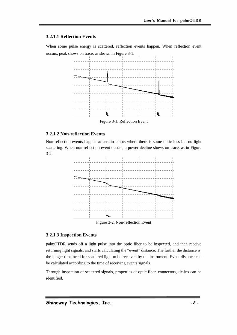
3.2.1.1 Reflection Events
When some pulse energy is scattered, reflection events happen. When reflection event
occurs, peak shows on trace, as shown in Figure 3-1.
Figure 3-1. Reflection Event
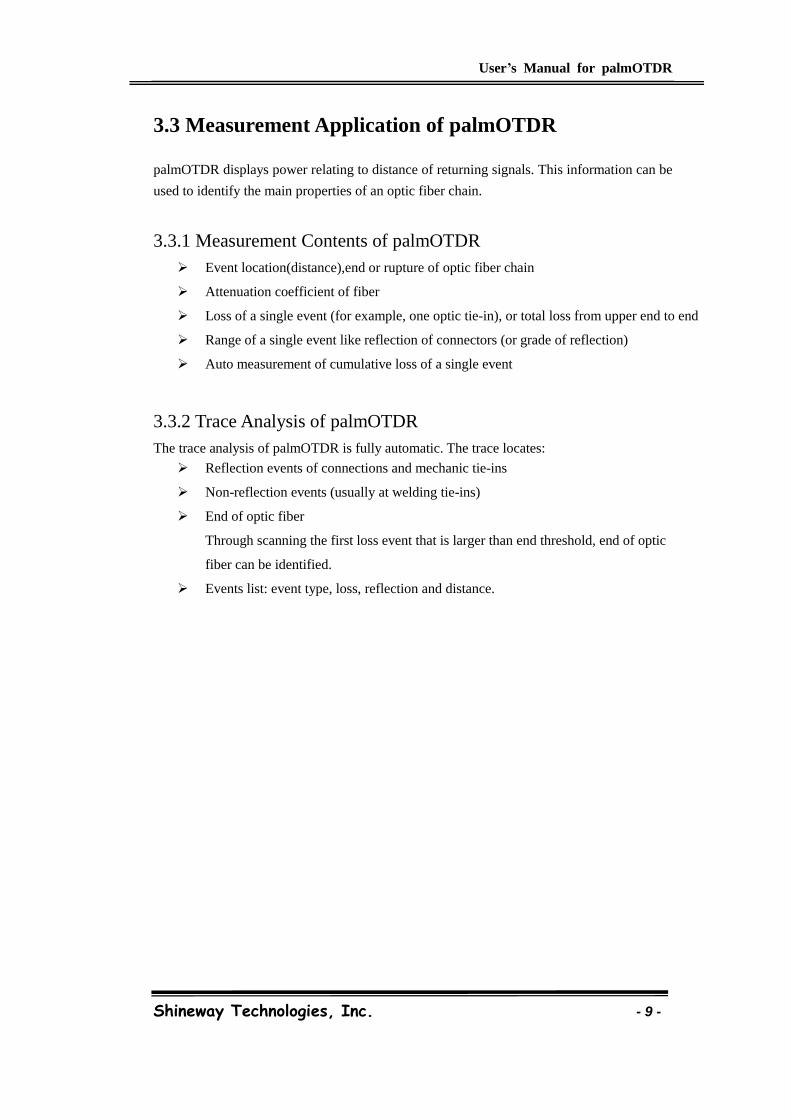
3.2.1.2 Non-reflection Events
Non-reflection events happen at certain points where there is some optic loss but no light
scattering. When non-reflection event occurs, a power decline shows on trace, as in Figure
3-2.
Figure 3-2. Non-reflection Event
3.2.1.3 Inspection Events
palmOTDR sends off a light pulse into the optic fiber to be inspected, and then receive
returning light signals, and starts calculating the “event” distance. The farther the distance is,
the longer time need for scattered light to be received by the instrument. Event distance can
be calculated according to the time of receiving events signals.
Through inspection of scattered signals, properties of optic fiber, connectors, tie-ins can be
identified.
User’s Manual for palmOTDR
Shineway Technologies, Inc. - 9 -
3.3 Measurement Application of palmOTDR
palmOTDR displays power relating to distance of returning signals. This information can be
used to identify the main properties of an optic fiber chain.
3.3.1 Measurement Contents of palmOTDR
Event location(distance),end or rupture of optic fiber chain
Attenuation coefficient of fiber
Loss of a single event (for example, one optic tie-in), or total loss from upper end to end
Range of a single event like reflection of connectors (or grade of reflection)
Auto measurement of cumulative loss of a single event
3.3.2 Trace Analysis of palmOTDR
The trace analysis of palmOTDR is fully automatic. The trace locates:
Reflection events of connections and mechanic tie-ins
Non-reflection events (usually at welding tie-ins)
End of optic fiber
Through scanning the first loss event that is larger than end threshold, end of optic
fiber can be identified.
Events list: event type, loss, reflection and distance.
User’s Manual for palmOTDR
Shineway Technologies, Inc. - 10 -
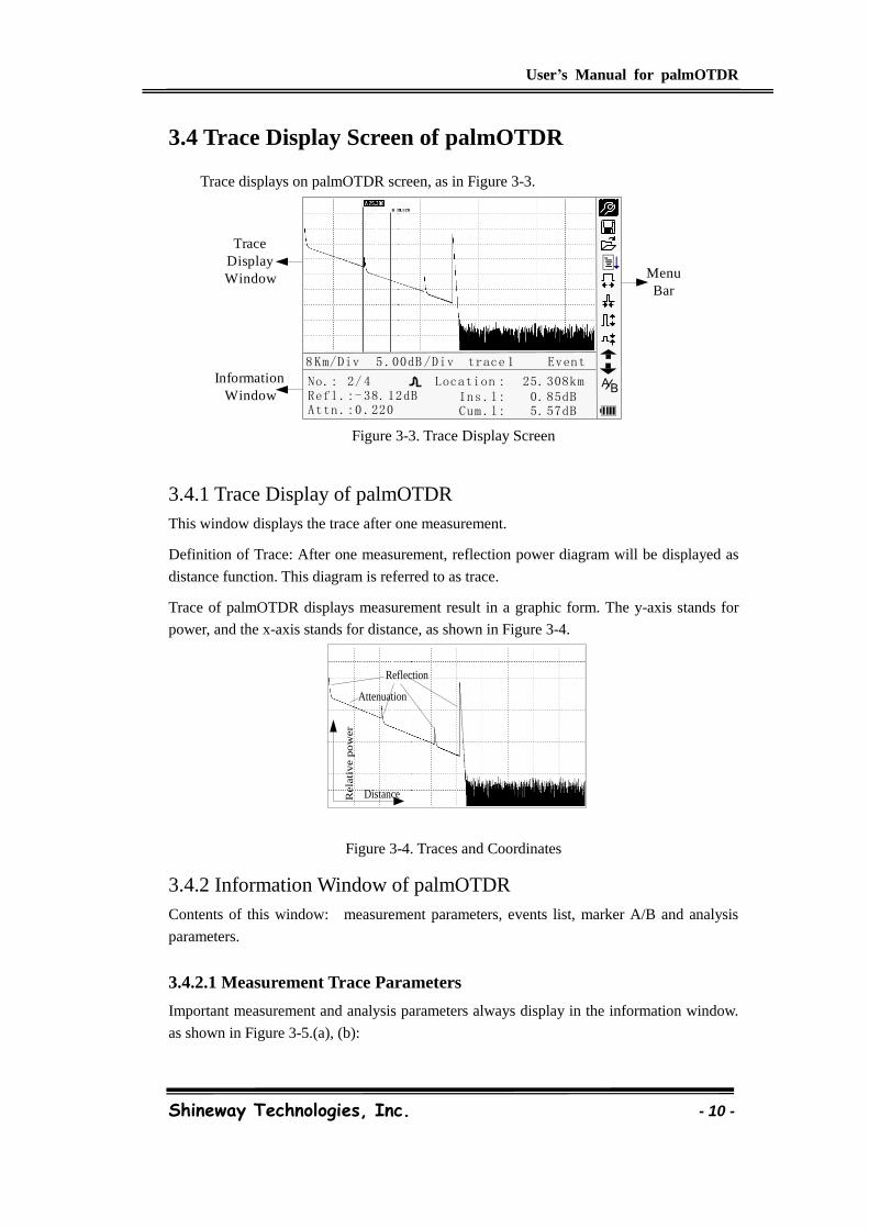
3.4 Trace Display Screen of palmOTDR
Trace displays on palmOTDR screen, as in Figure 3-3.
8 Km/Div 5 .00dB /Div trace 1
No.: 2/ 4
Attn .:0 .220
Location : 25. 308kmRefl .:- 38. 12dB Ins .l: 0. 85dB
Cum .l: 5. 57dB
Menu
Bar
Trace
Display
Window
Information
WindowBA
Event
Figure 3-3. Trace Display Screen
3.4.1 Trace Display of palmOTDR
This window displays the trace after one measurement.
Definition of Trace: After one measurement, reflection power diagram will be displayed as
distance function. This diagram is referred to as trace.
Trace of palmOTDR displays measurement result in a graphic form. The y-axis stands for
power, and the x-axis stands for distance, as shown in Figure 3-4.
Reflection
Attenuation
Rela
tive p
ow
er
Distance
Figure 3-4. Traces and Coordinates
3.4.2 Information Window of palmOTDR
Contents of this window: measurement parameters, events list, marker A/B and analysis
parameters.
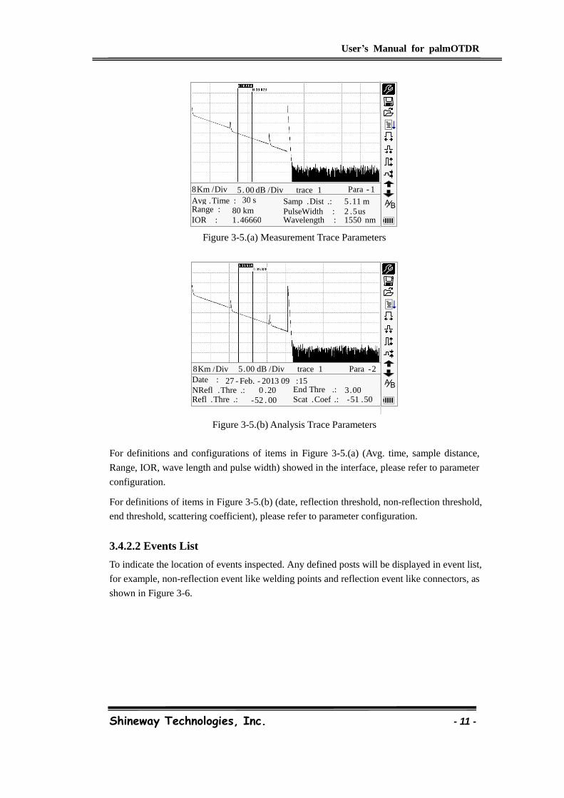
3.4.2.1 Measurement Trace Parameters
Important measurement and analysis parameters always display in the information window.
as shown in Figure 3-5.(a), (b):
User’s Manual for palmOTDR
Shineway Technologies, Inc. - 11 -
Figure 3-5.(a) Measurement Trace Parameters
Figure 3-5.(b) Analysis Trace Parameters
For definitions and configurations of items in Figure 3-5.(a) (Avg. time, sample distance,
Range, IOR, wave length and pulse width) showed in the interface, please refer to parameter
configuration.
For definitions of items in Figure 3-5.(b) (date, reflection threshold, non-reflection threshold,
end threshold, scattering coefficient), please refer to parameter configuration.
3.4.2.2 Events List
To indicate the location of events inspected. Any defined posts will be displayed in event list,
for example, non-reflection event like welding points and reflection event like connectors, as
shown in Figure 3-6.
30 s 80 km 1 . 46660
2 . 5 us 1550 nm
Avg . Time : Range : IOR :
PulseWidth : Wavelength :
8 Km / Div 5 . 00 dB / Div trace 1 Para - 1
B A Samp . Dist .: 5 . 11 m
Date : 27 - Feb. - 2013 09 : 15 NRefl . Thre .:
- 52 . 00 Refl . Thre .: 3 . 00 End Thre .: - 51 . 50
0 . 20 Scat . Coef .:
8 Km / Div 5 . 00 dB / Div trace 1 Para - 2
B A
User’s Manual for palmOTDR
Shineway Technologies, Inc. - 12 -
No.: 2/4
At t n.: 0. 220
L oc a t i on: 25.308 km
Re fl .: -38 .12dB Ins .L.: 0. 85dBCum .L.: 5. 57dB
8Km /Di v 5. 00dB /Di v t ra c e1 E ve nt
BA
Figure 3-6. Events List
No: Event sequence No;
Four types of events:
Begin end; Reflection event; Fiber end; Attenuation event;
Loc.: Distance from beginning point to event;
Refl.: Magnitude of reflection;
Insl.: Loss of Inserted event;
Attn.: Attenuation characteristic from one event point to the current event.
Cuml.: Cumulative loss, calculating from beginning point to the current event.
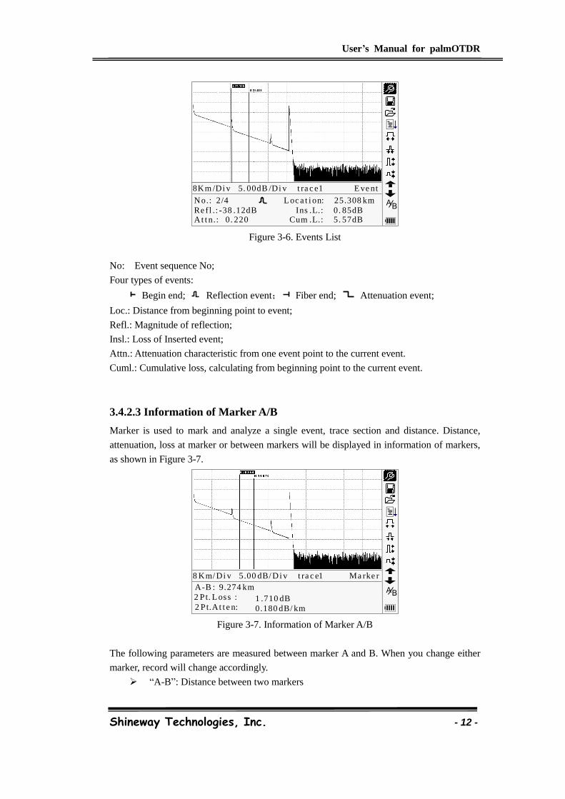
3.4.2.3 Information of Marker A/B
Marker is used to mark and analyze a single event, trace section and distance. Distance,
attenuation, loss at marker or between markers will be displayed in information of markers,
as shown in Figure 3-7.
A-B : 9.274 km
1 .710 dB
0.180 dB/ km
2 Pt. L oss :
2 Pt.At t e n:
8 Km/ Di v 5.00 dB/ Di v t ra c e1 Ma rke r
BA
Figure 3-7. Information of Marker A/B
The following parameters are measured between marker A and B. When you change either
marker, record will change accordingly.
“A-B”: Distance between two markers
User’s Manual for palmOTDR
Shineway Technologies, Inc. - 13 -
“2 points loss”: Loss between two markers; power difference between two
markers
“2 points attenuation”: 2 points loss of unit length
The specific operations of the above are to be elaborated afterwards.
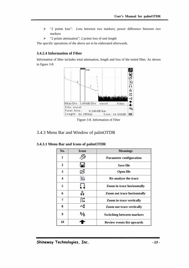
3.4.2.4 Information of Fiber
Information of fiber includes total attenuation, length and loss of the tested fiber. As shown
in figure 3-8.
Fi l e: t ra c e1
14. 920dB
0.240 dB /kmT ot a l At t n.:
L e ngt h:
8 Km/ Di v 5.00 dB/ Di v t ra c e1 Fi be r
BA
62 .180 km L oss :
Figure 3-8. Information of Fiber
3.4.3 Menu Bar and Window of palmOTDR
3.4.3.1 Menu Bar and Icons of palmOTDR
No. Icons Meanings
1
Parameter configuration
2
Save file
3
Open file
4
Re-analyze the trace
5
Zoom in trace horizontally
6
Zoom out trace horizontally
7 Zoom in trace vertically
8 Zoom out trace vertically
9 BA
Switching between markers
10 Review events list upwards
User’s Manual for palmOTDR
Shineway Technologies, Inc. - 14 -
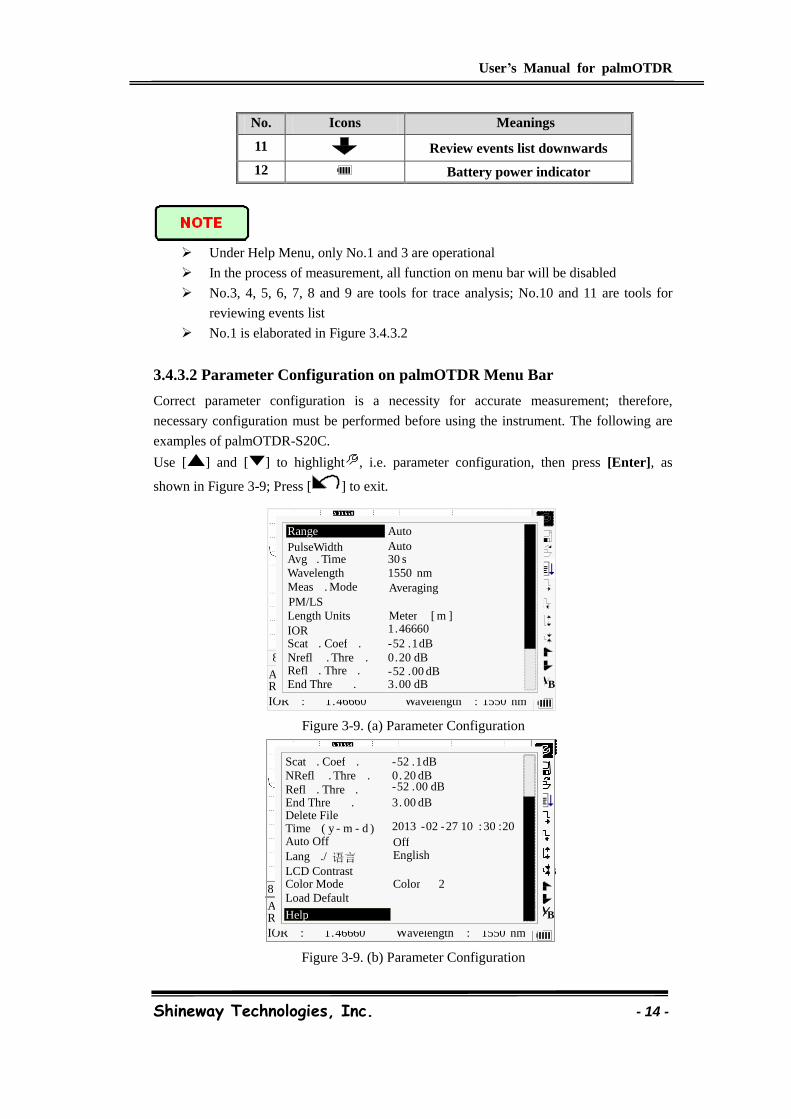
No. Icons Meanings
11 Review events list downwards
12 Battery power indicator
Under Help Menu, only No.1 and 3 are operational
In the process of measurement, all function on menu bar will be disabled
No.3, 4, 5, 6, 7, 8 and 9 are tools for trace analysis; No.10 and 11 are tools for
reviewing events list
No.1 is elaborated in Figure 3.4.3.2
3.4.3.2 Parameter Configuration on palmOTDR Menu Bar
Correct parameter configuration is a necessity for accurate measurement; therefore,
necessary configuration must be performed before using the instrument. The following are
examples of palmOTDR-S20C.
Use [ ] and [ ] to highlight , i.e. parameter configuration, then press [Enter], as
shown in Figure 3-9; Press [ ] to exit.
Figure 3-9. (a) Parameter Configuration
Figure 3-9. (b) Parameter Configuration
Ave . Time : Range : IOR :
8 Km / Div 3 . 50 dB / Div trace 1 . trc 15 : 20
1 . 46660 1550 nm Wavelength :
B A 30 s
80 km 2500 ns
Range
Wavelength 1550 nm
PulseWidth Auto Avg . Time 30 s
IOR 1 . 46660
Nrefl . Thre . 0 . 20 dB Refl . Thre . - 52 . 00 dB End Thre . 3 . 00 dB
Scat . Coef . - 52 . 1 dB
Averaging Meas . Mode
Auto
PM/LS Length Units Meter [ m ]
B A
1 . 46660 1550 nm
Ave . Time : Range : IOR : Wavelength :
8 Km / Div 3 . 50 dB / Div trace 1 . trc 15 : 20
B A
30 s 80 km
2500 ns
Pulsewidth : Load Default
Help
Lang ./ 语言 LCD Contrast
Auto Off Off English
NRefl . Thre . 0 . 20 dB Refl . Thre . - 52 . 00 dB
End Thre . 3 . 00 dB
Scat . Coef . - 52 . 1 dB
Delete File Time ( y - m - d ) 2013 - 02 - 27 10 : 30 : 20
Color Mode Color 2

User’s Manual for palmOTDR
Shineway Technologies, Inc. - 15 -
3.4.3.2.1 Definitions of Measurement Parameters
Parameter Definition of Parameter
Range Length of optic fiber relevant to the trace
Pulse Width Width of laser pulse sending out from OTDR to optic fiber
Average Time To select suitable testing time.
Wave length To select laser wave length for measurement
Measurement Mode To select mode for measurement
VFL Power on or off visible laser(For B/N, C/N & D/N only)
Length Units To select length units
IOR IOR of optic fiber which affects the transmission speed of laser
Scatter Coefficient Which affects backward scatter power of laser in fiber
Non reflection threshold Events whose insertion loss is greater than the threshold displays here
Reflection threshold Reflection events GE the threshold will be displayed.
End threshold The first event with insertion loss GE the threshold is considered the
end of fiber, and all following events will be ignored
Delete Files Delete stored trace data in the instrument
Time Show current system time
Auto Off On or off of Auto off function
Lang./语言 Choose the language
LCD contrast Adjust the contrast of LCD to select
Color mode setting Select suitable displaying color setting
Load Default Set all parameters to factory setting
Help Show help files (Quick Reference)
3.4.3.2.2 Range Configuration
Generally, range will be set according to actual length of optic fiber, so as to insure the
accuracy of measurement.
Under the menu of parameter configuration, use [ ] and [ ] to highlight “Range”;
Press [Enter] to enter, as shown in Figure 3-10; press [ ] to exit.
Figure 3-10. Set Range
3 . 00 dB 30 s
80 km 1 . 46660
2500 ns 1550 nm
Ave . Time : Range : IOR :
Pulsewidth : Wavelength :
8 Km / Div 3 . 50 dB / Div trace 1 . trc 15 : 20
Auto 1 . 3 km 2 . 5 km 5 . 0 km 10 km 20 km 40 km 80 km
120 km
B A 30 s
80 km 2500 ns
Range
Wavelength 1550 nm
PulseWidth Auto Avg . Time 30 s
IOR
1 . 4659
Nrefl . Thre .
0 . 20 dB
Refl . Thre .
- 52 . 00 dB
End Thre .
3 . 00 dB Scat . Coef .
- 51 . 50 dB
Averaging Meas . Mode
Auto Auto
1 . 3 km 2 . 5 km 5 km 10 km 20 km 40 km 80 km
240 km
300 m
160 km
PM/LS Length Units
User’s Manual for palmOTDR
Shineway Technologies, Inc. - 16 -
Use [ ] and [ ] to select adequate range; Press [Enter] to confirm.
“Auto” means the automatic measurement. When this function is selected, the
instrument will automatically make an intelligentized selection of adequate range
and pulse width for measurement. The whole process of measurement does not
need any intervention of the operator
“Auto” means the default setting
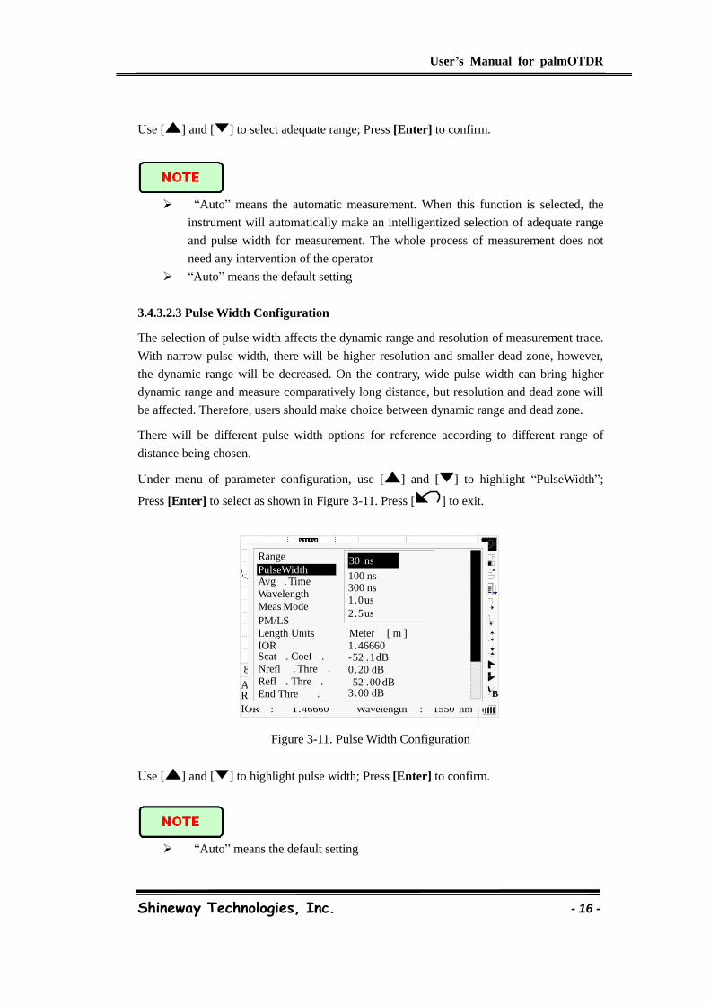
3.4.3.2.3 Pulse Width Configuration
The selection of pulse width affects the dynamic range and resolution of measurement trace.
With narrow pulse width, there will be higher resolution and smaller dead zone, however,
the dynamic range will be decreased. On the contrary, wide pulse width can bring higher
dynamic range and measure comparatively long distance, but resolution and dead zone will
be affected. Therefore, users should make choice between dynamic range and dead zone.
There will be different pulse width options for reference according to different range of
distance being chosen.
Under menu of parameter configuration, use [ ] and [ ] to highlight “PulseWidth”;
Press [Enter] to select as shown in Figure 3-11. Press [ ] to exit.
Figure 3-11. Pulse Width Configuration
Use [ ] and [ ] to highlight pulse width; Press [Enter] to confirm.
“Auto” means the default setting
30 s 80 km 1 . 46660
2500 ns 1550 nm
Ave . Time : Range : IOR :
Pulsewidth : Wavelength :
8 Km / Div 3 . 50 dB / Div trace 1 . trc 15 : 20
30 ns 100 ns 275 ns 1 . 0 us 2 . 5 us
B A 30 s
80 km 2500 ns
Range
Wavelength 1550 nm
PulseWidth Auto Avg . Time 30 s
IOR 1 . 46660
Nrefl . Thre . 0 . 20 dB Refl . Thre . - 52 . 00 dB End Thre . 3 . 00 dB
Scat . Coef . - 52 . 1 dB
Averaging Meas Mode
Auto 30 ns
100 ns 300 ns 1 . 0 us 2 . 5 us
PM/LS Length Units Meter [ m ]
User’s Manual for palmOTDR
Shineway Technologies, Inc. - 17 -
When Range is set to “Auto”, pulse width will automatically become “Auto”
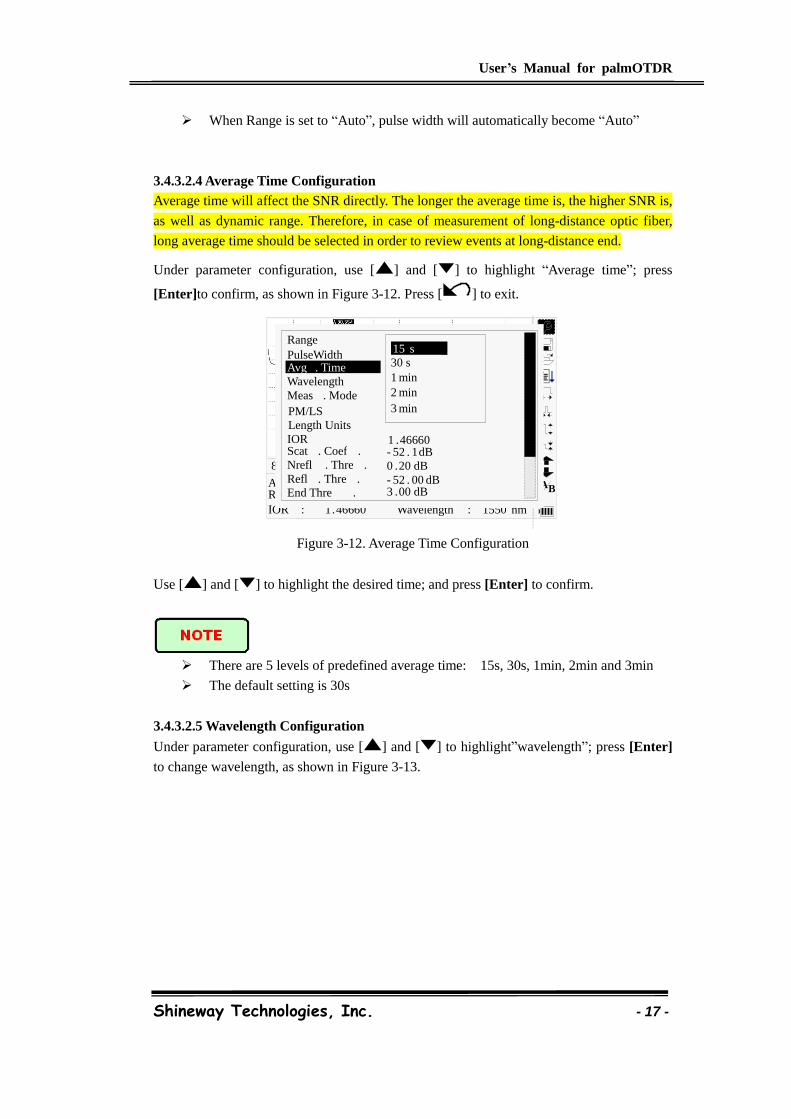
3.4.3.2.4 Average Time Configuration
Average time will affect the SNR directly. The longer the average time is, the higher SNR is,
as well as dynamic range. Therefore, in case of measurement of long-distance optic fiber,
long average time should be selected in order to review events at long-distance end.
Under parameter configuration, use [ ] and [ ] to highlight “Average time”; press
[Enter]to confirm, as shown in Figure 3-12. Press [ ] to exit.
Figure 3-12. Average Time Configuration
Use [ ] and [ ] to highlight the desired time; and press [Enter] to confirm.
There are 5 levels of predefined average time: 15s, 30s, 1min, 2min and 3min
The default setting is 30s
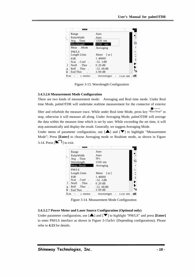
3.4.3.2.5 Wavelength Configuration
Under parameter configuration, use [ ] and [ ] to highlight”wavelength”; press [Enter]
to change wavelength, as shown in Figure 3-13.
30 s 80 km 1 . 46660
2500 ns 1550 nm
Ave . Time : Range : IOR :
Pulsewidth : Wavelength :
8 Km / Div 3 . 50 dB / Div trace 1 . trc 15 : 20
B A 30 s 80 km 2500 ns
Range
Wavelength 1550 nm
PulseWidth Auto Avg . Time 30 s
IOR
1 . 4659
Nrefl . Thre . 0 . 20 dB Refl . Thre . - 52 . 00 dB End Thre . 3 . 00 dB
Scat . Coef . - 52 . 1 dB
Averaging Meas . Mode
Auto 15 s 30 s 1 min 2 min
3 min PM/LS Length Units
1 . 46660
User’s Manual for palmOTDR
Shineway Technologies, Inc. - 18 -
Figure 3-13. Wavelength Configuration
3.4.3.2.6 Measurement Mode Configuration
There are two kinds of measurement mode: Averaging and Real time mode. Under Real
time Mode, palmOTDR will undertake realtime measurement for the connector of exterior
fiber and refurbish the measure trace. While under Real time Mode, press key “ ” to
stop, otherwise it will measure all along. Under Averaging Mode, palmOTDR will average
the data within the measure time which is set by user. While exceeding the set time, it will
stop automatically and display the result. Generally, we suggest Averaging Mode.
Under menu of parameter configuration, use [ ] and [ ] to highlight “Measurement
Mode”; Press [Enter] to choose Averaging mode or Realtime mode, as shown in Figure
3-14. Press [ ] to exit.
Figure 3-14. Measurement Mode Configuration
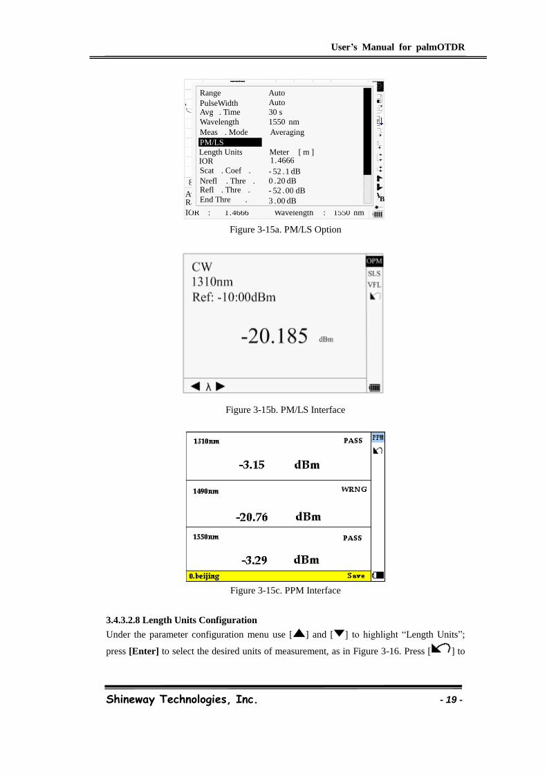
3.4.3.2.7 Power Meter and Laser Source Configuration (Optional only)
Under parameter configuration, use [ ] and [ ] to highlight “PM/LS” and press [Enter]
to enter PM/LS interface as shown in Figure 3-15a/b/c (Depending configurations). Please
refer to 4.13 for details.
1 . 46660 1550 nm
Ave . Time : Range : IOR : Wavelength :
8 Km / Div 3 . 50 dB / Div trace 1 . trc 15 : 20
B A 30 s
80 km 2500 ns
Range
Wavelength 1550 nm
PulseWidth Auto Avg . Time 30 s
IOR 1 . 46660
Nrefl . Thre . 0 . 20 dB Refl . Thre . - 52 . 00 dB End Thre . 3 . 00 dB
Scat . Coef . - 52 . 1 dB
Averaging Meas . Mode
Auto
1550 nm 1310 nm
PM/LS Length Units Meter [ m ]
30 s 80 km 1 . 46660
2500 ns 1550 nm
Ave . Time : Range : IOR :
Pulsewidth : Wavelength :
8 Km / Div 3 . 50 dB / Div trace 1 . trc 15 : 20
B A 30 s
80 km 2500 ns
Range
Wavelength 1550 nm
PulseWidth Auto Avg . Time 30 s
IOR 1 . 46660
Nrefl . Thre . 0 . 20 dB Refl . Thre . - 52 . 00 dB End Thre . 3 . 00 dB
Scat . Coef . - 52 . 1 dB
Averaging Meas . Mode
Auto
PM/LS Length Units Meter [ m ]
User’s Manual for palmOTDR
Shineway Technologies, Inc. - 19 -
Figure 3-15a. PM/LS Option
Figure 3-15b. PM/LS Interface
Figure 3-15c. PPM Interface
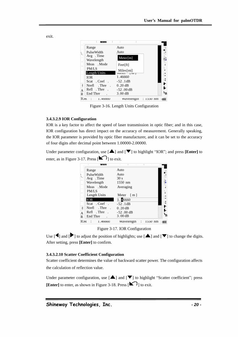
3.4.3.2.8 Length Units Configuration
Under the parameter configuration menu use [ ] and [ ] to highlight “Length Units”;
press [Enter] to select the desired units of measurement, as in Figure 3-16. Press [ ] to
1 . 4666 1550 nm
Ave . Time : Range : IOR : Wavelength :
8 Km / Div 3 . 50 dB / Div trace 1 . trc 15 : 20
1 . 4659 4
B A 30 s 80 km 2500 ns
Range
Wavelength 1550 nm
PulseWidth Auto Avg . Time 30 s
PM/LS
Nrefl . Thre . 0 . 20 dB Refl . Thre . - 52 . 00 dB End Thre . 3 . 00 dB
Scat . Coef . - 52 . 1 dB
Averaging Meas . Mode
Auto
IOR 1 . 4666 Length Units Meter [ m ]
User’s Manual for palmOTDR
Shineway Technologies, Inc. - 20 -
exit.
Figure 3-16. Length Units Configuration
3.4.3.2.9 IOR Configuration
IOR is a key factor to affect the speed of laser transmission in optic fiber; and in this case,
IOR configuration has direct impact on the accuracy of measurement. Generally speaking,
the IOR parameter is provided by optic fiber manufacturer, and it can be set to the accuracy
of four digits after decimal point between 1.00000-2.00000.
Under parameter configuration, use [ ] and [ ] to highlight “IOR”; and press [Enter] to
enter, as in Figure 3-17. Press [ ] to exit.
Figure 3-17. IOR Configuration
Use [ ] and [ ] to adjust the position of highlights; use [ ] and [ ] to change the digits.
After setting, press [Enter] to confirm.
3.4.3.2.10 Scatter Coefficient Configuration
Scatter coefficient determines the value of backward scatter power. The configuration affects
the calculation of reflection value.
Under parameter configuration, use [ ] and [ ] to highlight “Scatter coefficient”; press
[Enter] to enter, as shown in Figure 3-18. Press [ ] to exit.
Ave . Time : Range : IOR :
8 Km / Div 3 . 50 dB / Div trace 1 . trc 15 : 20
1 . 46660 1550 nm Wavelength :
B A 30 s
80 km 2500 ns
Range
Wavelength 1550 nm
PulseWidth Auto Avg . Time 30 s
IOR 1 . 46660
Nrefl . Thre . 0 . 20 dB Refl . Thre . - 52 . 00 dB End Thre . 3 . 00 dB
Scat . Coef . - 52 . 1 dB
Averaging Meas . Mode
Auto
PM/LS Off Length Units Meter [ m ]
Feet [ ft ]
Miles [ mi ]
Meter [ m ]
1 . 46660 1550 nm
Ave . Time : Range : IOR : Wavelength :
8 Km / Div 3 . 50 dB / Div trace 1 . trc 15 : 20
1 . 4659 4
B A 30 s 80 km 2500 ns
Range
Wavelength 1550 nm
PulseWidth Auto Avg . Time 30 s
IOR
Nrefl . Thre . 0 . 20 dB Refl . Thre . - 52 . 00 dB End Thre . 3 . 00 dB
Scat . Coef . - 52 . 1 dB
Averaging Meas . Mode
Auto
1 . 6660 4
PM/LS Length Units Meter [ m ]
User’s Manual for palmOTDR
Shineway Technologies, Inc. - 21 -
Figure 3-18. Scatter Coefficient Configuration
Use [ ] and [ ] to adjust the position of highlights; use [ ] and [ ] to change the digits.
After setting, press [Enter] to confirm.
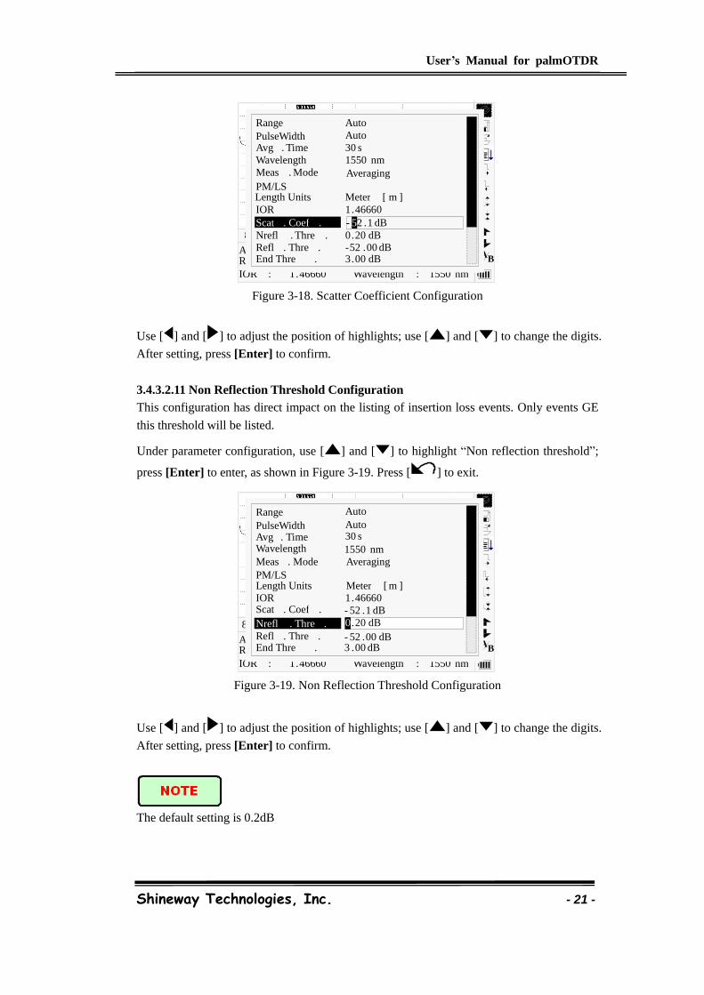
3.4.3.2.11 Non Reflection Threshold Configuration
This configuration has direct impact on the listing of insertion loss events. Only events GE
this threshold will be listed.
Under parameter configuration, use [ ] and [ ] to highlight “Non reflection threshold”;
press [Enter] to enter, as shown in Figure 3-19. Press [ ] to exit.
Figure 3-19. Non Reflection Threshold Configuration
Use [ ] and [ ] to adjust the position of highlights; use [ ] and [ ] to change the digits.
After setting, press [Enter] to confirm.
The default setting is 0.2dB
30 s 80 km 1 . 46660
2500 ns 1550 nm
Ave . Time : Range : IOR :
Pulsewidth : Wavelength :
8 Km / Div 3 . 50 dB / Div trace 1 . trc 15 : 20
- 51 . 50 dB 5
B A 30 s
80 km 2500 ns
Range
Wavelength 1550 nm
PulseWidth Auto Avg . Time 30 s
IOR 1 . 46660
Nrefl . Thre . 0 . 20 dB Refl . Thre . - 52 . 00 dB End Thre . 3 . 00 dB
Scat . Coef .
Averaging Meas . Mode
Auto
- 52 . 1 dB 5
PM/LS Length Units Meter [ m ]
1 . 46660 1550 nm
Ave . Time : Range : IOR : Wavelength :
8 Km / Div 3 . 50 dB / Div trace 1 . trc 15 : 20
0 . 20 dB 0
B A 30 s
80 km 2500 ns
Range
Wavelength 1550 nm
PulseWidth Auto Avg . Time 30 s
IOR 1 . 46660
Nrefl . Thre . Refl . Thre . - 52 . 00 dB End Thre . 3 . 00 dB
Scat . Coef . - 52 . 1 dB
Averaging Meas . Mode
Auto
0 . 20 dB 0
PM/LS Length Units Meter [ m ]
User’s Manual for palmOTDR
Shineway Technologies, Inc. - 22 -
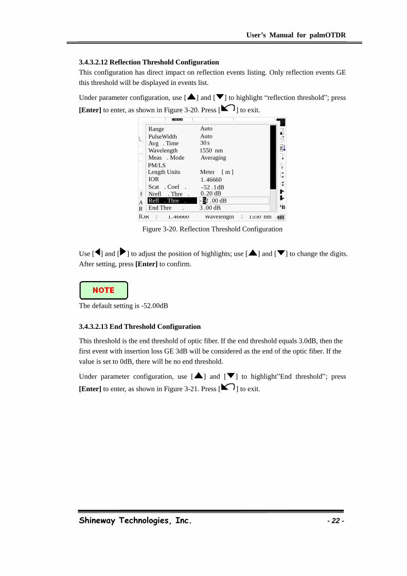
3.4.3.2.12 Reflection Threshold Configuration
This configuration has direct impact on reflection events listing. Only reflection events GE
this threshold will be displayed in events list.
Under parameter configuration, use [ ] and [ ] to highlight “reflection threshold”; press
[Enter] to enter, as shown in Figure 3-20. Press [ ] to exit.
Figure 3-20. Reflection Threshold Configuration
Use [ ] and [ ] to adjust the position of highlights; use [ ] and [ ] to change the digits.
After setting, press [Enter] to confirm.
The default setting is -52.00dB
3.4.3.2.13 End Threshold Configuration
This threshold is the end threshold of optic fiber. If the end threshold equals 3.0dB, then the
first event with insertion loss GE 3dB will be considered as the end of the optic fiber. If the
value is set to 0dB, there will be no end threshold.
Under parameter configuration, use [ ] and [ ] to highlight”End threshold”; press
[Enter] to enter, as shown in Figure 3-21. Press [ ] to exit.
30 s 80 km 1 . 46660
2500 ns 1550 nm
Ave . Time : Range : IOR :
Pulsewidth : Wavelength :
8 Km / Div 3 . 50 dB / Div trace 1 . trc 15 : 20
- 52 . 00 dB 5
B A 30 s
80 km 2500 ns
Range
Wavelength 1550 nm
PulseWidth Auto Avg . Time 30 s
IOR 1 . 46660
Nrefl . Thre . 0 . 20 dB Refl . Thre . End Thre . 3 . 00 dB
Scat . Coef . - 52 . 1 dB
Averaging Meas . Mode
Auto
- 52 . 00 dB 5
PM/LS Length Units Meter [ m ]
User’s Manual for palmOTDR
Shineway Technologies, Inc. - 23 -
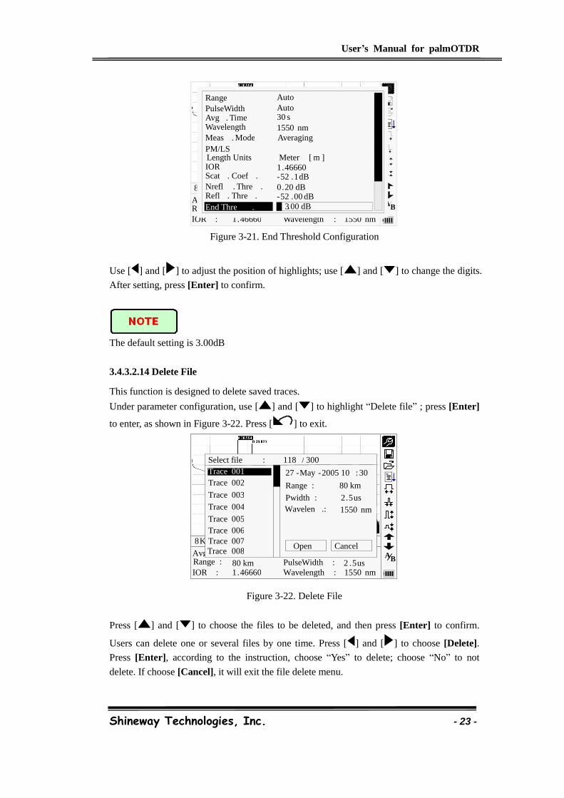
Figure 3-21. End Threshold Configuration
Use [ ] and [ ] to adjust the position of highlights; use [ ] and [ ] to change the digits.
After setting, press [Enter] to confirm.
The default setting is 3.00dB
3.4.3.2.14 Delete File
This function is designed to delete saved traces.
Under parameter configuration, use [ ] and [ ] to highlight “Delete file” ; press [Enter]
to enter, as shown in Figure 3-22. Press [ ] to exit.
Figure 3-22. Delete File
Press [ ] and [ ] to choose the files to be deleted, and then press [Enter] to confirm.
Users can delete one or several files by one time. Press [ ] and [ ] to choose [Delete].
Press [Enter], according to the instruction, choose “Yes” to delete; choose “No” to not
delete. If choose [Cancel], it will exit the file delete menu.
30 s 80 km 1 . 46660
2500 ns 1550 nm
Ave . Time : Range : IOR :
Pulsewidth : Wavelength :
8 Km / Div 3 . 50 dB / Div trace 1 . trc 15 : 20 3 . 00 dB 0
B A 30 s
80 km 2500 ns
Range
Wavelength 1550 nm
PulseWidth Auto Avg . Time 30 s
IOR 1 . 46660
Nrefl . Thre . 0 . 20 dB Refl . Thre . - 52 . 00 dB End Thre .
Scat . Coef . - 52 . 1 dB
Averaging Meas . Mode
Auto
3 . 00 dB
PM/LS Length Units Meter [ m ]
30 s 80 km 1 . 46660
2 . 5 us 1550 nm
Avg . Time : Range : IOR :
PulseWidth : Wavelength :
8 Km / Div 3 . 50 dB / Div trace 1 . trc 15 : 20
Select file : 118 / 300
Trace 001
Trace 002
Trace 003
Trace 004
Trace 005
Cancel Open
Trace 006 Trace 007 Trace 008
27 - May - 2005 10 : 30
Range : 80 km
Pwidth : 2 . 5 us Wavelen .: 1550 nm
B A
User’s Manual for palmOTDR
Shineway Technologies, Inc. - 24 -
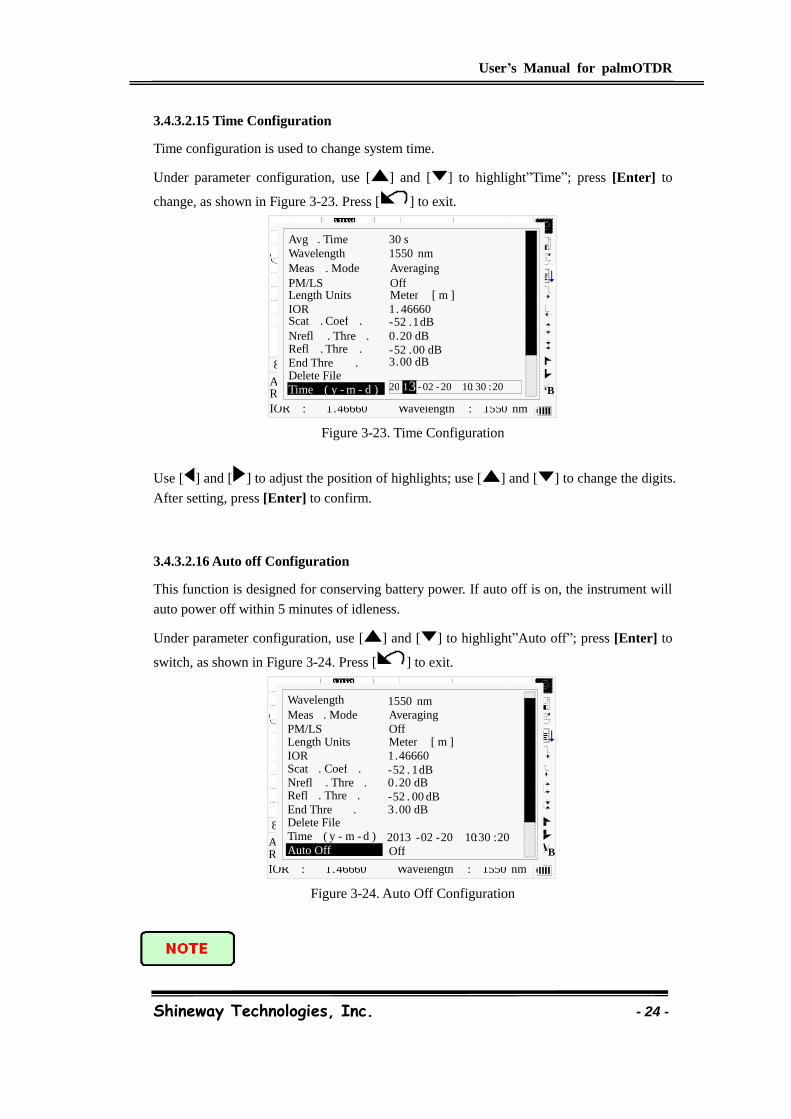
3.4.3.2.15 Time Configuration
Time configuration is used to change system time.
Under parameter configuration, use [ ] and [ ] to highlight”Time”; press [Enter] to
change, as shown in Figure 3-23. Press [ ] to exit.
Figure 3-23. Time Configuration
Use [ ] and [ ] to adjust the position of highlights; use [ ] and [ ] to change the digits.
After setting, press [Enter] to confirm.
3.4.3.2.16 Auto off Configuration
This function is designed for conserving battery power. If auto off is on, the instrument will
auto power off within 5 minutes of idleness.
Under parameter configuration, use [ ] and [ ] to highlight”Auto off”; press [Enter] to
switch, as shown in Figure 3-24. Press [ ] to exit.
Figure 3-24. Auto Off Configuration
30 s 80 km 1 . 46660
2500 ns 1550 nm
Ave . Time : Range : IOR :
Pulsewidth : Wavelength :
8 Km / Div 3 . 50 dB / Div trace 1 . trc 15 : 20
20 - 12 - 10 10 : 30 : 20 0 3 B A 30 s
80 km 2500 ns
Wavelength 1550 nm Avg . Time 30 s
IOR 1 . 46660
Nrefl . Thre . 0 . 20 dB Refl . Thre . - 52 . 00 dB End Thre . 3 . 00 dB
Scat . Coef . - 52 . 1 dB
Averaging Meas . Mode
Delete File Time ( y - m - d ) 20 - 02 - 20 10 : 30 : 20 1 3
PM/LS Off Length Units Meter [ m ]
1 . 46660 1550 nm
Ave . Time : Range : IOR : Wavelength :
8 Km / Div 3 . 50 dB / Div trace 1 . trc 15 : 20
B A 2500 ns
Wavelength 1550 nm
IOR 1 . 46660
Nrefl . Thre . 0 . 20 dB Refl . Thre . - 52 . 00 dB End Thre . 3 . 00 dB
Scat . Coef . - 52 . 1 dB
Averaging Meas . Mode
Delete File Time ( y - m - d ) 2013 - 02 - 20 10 : 30 : 20 Auto Off Off
PM/LS Off Length Units Meter [ m ]
User’s Manual for palmOTDR
Shineway Technologies, Inc. - 25 -
The default setting is “auto off” on
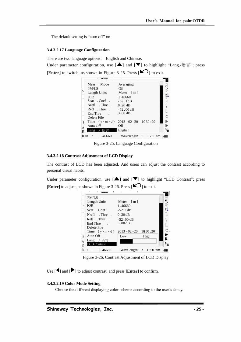
3.4.3.2.17 Language Configuration
There are two language options: English and Chinese.
Under parameter configuration, use [ ] and [ ] to highlight “Lang./语言”; press
[Enter] to switch, as shown in Figure 3-25. Press [ ] to exit.
Figure 3-25. Language Configuration
3.4.3.2.18 Contrast Adjustment of LCD Display
The contrast of LCD has been adjusted. And users can adjust the contrast according to
personal visual habits.
Under parameter configuration, use [ ] and [ ] to highlight “LCD Contrast”; press
[Enter] to adjust, as shown in Figure 3-26. Press [ ] to exit.
Figure 3-26. Contrast Adjustment of LCD Display
Use [ ] and [ ] to adjust contrast, and press [Enter] to confirm.
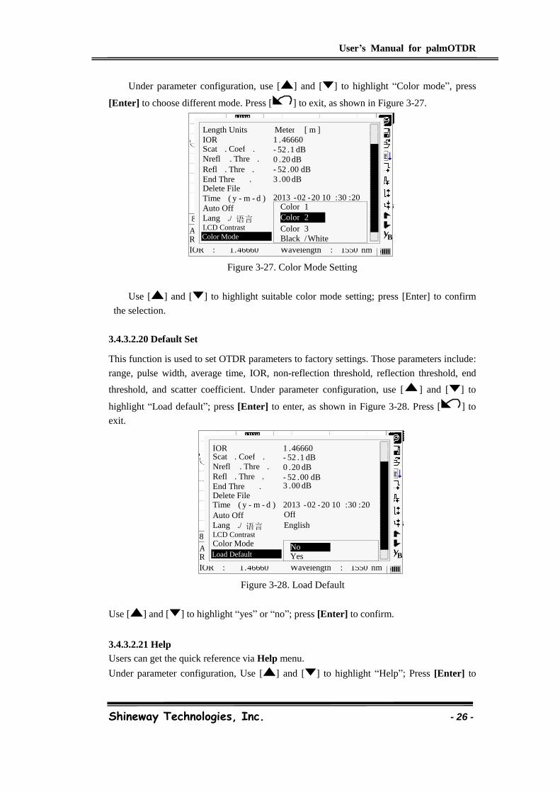
3.4.3.2.19 Color Mode Setting
Choose the different displaying color scheme according to the user’s fancy.
1 . 46660 1550 nm
Ave . Time : Range : IOR : Wavelength :
8 Km / Div 3 . 50 dB / Div trace 1 . trc 15 : 20
B A 2500 ns
IOR 1 . 46660
Nrefl . Thre . 0 . 20 dB Refl . Thre . - 52 . 00 dB End Thre . 3 . 00 dB
Scat . Coef . - 52 . 1 dB
Averaging Meas . Mode
Delete File Time ( y - m - d ) 2013 - 02 - 20 10 : 30 : 20 Auto Off Off Lang ./ 语言 English
PM/LS Off Length Units Meter [ m ]
B A
1 . 46660 1550 nm
Ave . Time : Range : IOR :
8 Km / Div 3 . 50 dB / Div trace 1 . trc 15 : 20
Wavelength :
B A 2500 ns
IOR 1 . 46660
Nrefl . Thre . 0 . 20 dB Refl . Thre . - 52 . 00 dB End Thre . 3 . 00 dB
Scat . Coef . - 52 . 1 dB
Delete File Time ( y - m - d ) 2013 - 02 - 20 10 : 30 : 20 Auto Off Off Lang ./ 语言 English LCD Contrast
Low High
PM/LS Length Units Meter [ m ]
User’s Manual for palmOTDR
Shineway Technologies, Inc. - 26 -
Under parameter configuration, use [ ] and [ ] to highlight “Color mode”, press
[Enter] to choose different mode. Press [ ] to exit, as shown in Figure 3-27.
Figure 3-27. Color Mode Setting
Use [ ] and [ ] to highlight suitable color mode setting; press [Enter] to confirm
the selection.
3.4.3.2.20 Default Set
This function is used to set OTDR parameters to factory settings. Those parameters include:
range, pulse width, average time, IOR, non-reflection threshold, reflection threshold, end
threshold, and scatter coefficient. Under parameter configuration, use [ ] and [ ] to
highlight “Load default”; press [Enter] to enter, as shown in Figure 3-28. Press [ ] to
exit.
Figure 3-28. Load Default
Use [ ] and [ ] to highlight “yes” or “no”; press [Enter] to confirm.
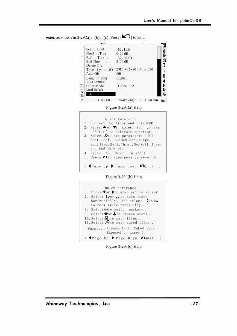
3.4.3.2.21 Help
Users can get the quick reference via Help menu.
Under parameter configuration, Use [ ] and [ ] to highlight “Help”; Press [Enter] to
B A
1 . 46660 1550 nm
Ave . Time : Range : IOR : Wavelength :
8 Km / Div 3 . 50 dB / Div trace 1 . trc 15 : 20
B A 2500 ns
IOR 1 . 46660
Nrefl . Thre . 0 . 20 dB Refl . Thre . - 52 . 00 dB End Thre . 3 . 00 dB
Scat . Coef . - 52 . 1 dB
Delete File Time ( y - m - d ) 2013 - 02 - 20 10 : 30 : 20 Auto Off Off Lang ./ 语言 English LCD Contrast Color Mode
Color 2
Color 3
Color 1
Black / White
Length Units Meter [ m ]
B A
1 . 46660 1550 nm
Ave . Time : Range : IOR : Wavelength :
8 Km / Div 3 . 50 dB / Div trace 1 . trc 15 : 20
B A 2500 ns
IOR 1 . 46660
Nrefl . Thre . 0 . 20 dB Refl . Thre . - 52 . 00 dB End Thre . 3 . 00 dB
Scat . Coef . - 52 . 1 dB
Delete File Time ( y - m - d ) 2013 - 02 - 20 10 : 30 : 20 Auto Off Off Lang ./ 语言 English LCD Contrast
Load Default No Yes
Color Mode
User’s Manual for palmOTDR
Shineway Technologies, Inc. - 27 -
enter, as shown in 3-29.(a)、(b)、(c). Press [ ] to exit.
Figure 3-29. (a) Help
Quick reference
( P a g e U p P a g e D o w n Q u i t )
1. Connect the fiber and palmOTDR .2. Press or to select icon , Press
‘Enter ’to activate function .3. Select to set parameters : IOR, Scat .Coef ., pulsewidth , range ,
avg . Time ,Refl .Thre . ,NonRefl .Thre and End Thre etc .
4. Press ‘Run /Stop’ to start ...5. Press to view measure results .
Figure 3-29. (b) Help
Quick reference
Warning : Always Avoid Naked Eyes Exposed to Laser !
( P a g e U p P a g e D o w n Q u i t )
7. Select or to zoom trace
to zoom trace vertically . horizontally , and select or
6. Press or to move active marker
8. Select to switch markers . BA
9. Select or to browse event .
10. Select to save files .11. Select to open saved files .
Figure 3-29. (c) Help
1 . 46660 1550 nm
Ave . Time : Range : IOR : Wavelength :
8 Km / Div 3 . 50 dB / Div trace 1 . trc 15 : 20
B A
Nrefl . Thre . 0 . 20 dB Refl . Thre . - 52 . 00 dB End Thre . 3 . 00 dB
Scat . Coef . - 52 . 1 dB
Delete File Time ( y - m - d ) 2013 - 02 - 20 10 : 30 : 20 Auto Off Off Lang ./ 语言 English LCD Contrast
Load Default Help
Color Mode Color 2

User’s Manual for palmOTDR
Shineway Technologies, Inc. - 28 -
3.5 Battery Recharge Status
When the instrument is power off and powered through AC/DC adapter, the “CHARGE”
indicator on the coping (Figure 1.) will turn on. When batteries are fully recharged, the
indicator will turn off.
When the instrument is power on and powered through AC/DC adapter, the inside batteries
are automatically recharged. The meanings of signals are as follows:
The batteries are being recharged;
The batteries are fully recharged.
When the instrument is powered by inside rechargeable batteries, power volume of batteries
is shown on the LCD:
No power;
Low power;
Half power;
More than half power;
Full power.
User’s Manual for palmOTDR
Shineway Technologies, Inc. - 29 -
4. Trace Measurement and Processing of Existing
Traces
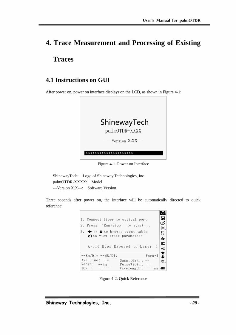
4.1 Instructions on GUI
After power on, power on interface displays on the LCD, as shown in Figure 4-1:
Figure 4-1. Power on Interface
ShinewayTech: Logo of Shineway Technologies, Inc.
palmOTDR-XXXX: Model
---Version X.X---: Software Version.
Three seconds after power on, the interface will be automatically directed to quick
reference:
1 . Connect fiber to optical port
2 . Press ‘Run /Stop’ to start ...
A v o i d E y e s E x p o s e d t o L a s e r !
-- s
-- km-.---- ---- nm
Ave. Time :Range :IOR : Wavelength :
-- Km/Div -- dB/ Div Para -1
3 . or to browse event table to view trace parameters
BA---PulseWidth :
Samp .Dist .: --
Figure 4-2. Quick Reference
ShinewayTech
palmOTDR - XXXX
--- Version X . XX ---
>>>>>>>>>>>>>>>>>>>>>
User’s Manual for palmOTDR
Shineway Technologies, Inc. - 30 -
4.2 Trace Measurement of palmOTDR
One complete trace can be obtained for each measurement. Also, palmOTDR can load a
saved trace.
Before each measurement, if the operator is not familiar with the cautions,
please do follow instructions in this manual for personal safety
Make sure that the optical fiber or cable is not in use and there is no laser
beam in the fiber before testing via palmOTDR. Otherwise, it may result in
imprecise test trace, even permanent damage for the palmOTDR
4.2.1 Trace Measurement- Connect Optical Fiber
Connect optic fiber to palmOTDR optic output directly, no tools needed.
Clean connectors,for details please refer to chapter A
Clean tie-ins and check whether they are FC/PC tie-ins or not
Connect optic fiber to the instrument
4.2.2 Trace Measurement - Parameter Configuration
For details relating to parameter configuration, please refer to 3.4.3.2, Parameter
Configuration on palmOTDR Menu Bar. If the parameters are unclear, please use the default
parameters of the instrument, however, this may cause an increase of measurements errors.
Range is set to “Auto”, when auto measurement is on.
4.2.3 Trace Measurement- Auto
Auto measurement can be applied in case that the length of optic fiber is unidentifiable.
palmOTDR auto select adequate range for measurement.
Steps for Auto measurement:
Parameter configuration: for detailed operations,please refer to
3.4.3.2,Parameter Configuration on palmOTDR Menu Bar. Set range to “AUTO”
Measure: press [ ] to start measurement, and the interface is as in Figure
4-3. (a), (b)
User’s Manual for palmOTDR
Shineway Technologies, Inc. - 31 -
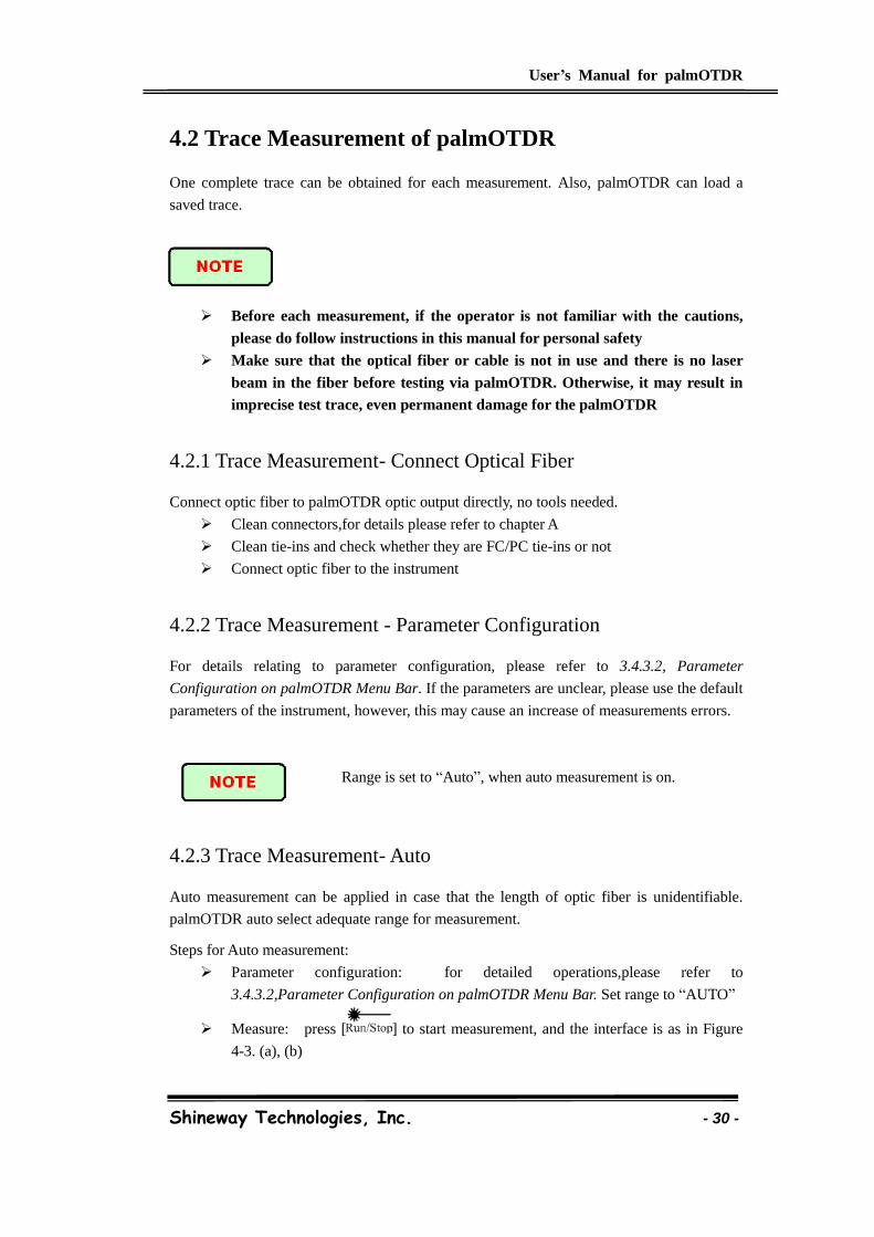
00 :30
00 :16
Ave .Time :
Time Passed :
8 Km/Div 5.00 dB/Div
BA
Figure 4-3.(a) Measuring
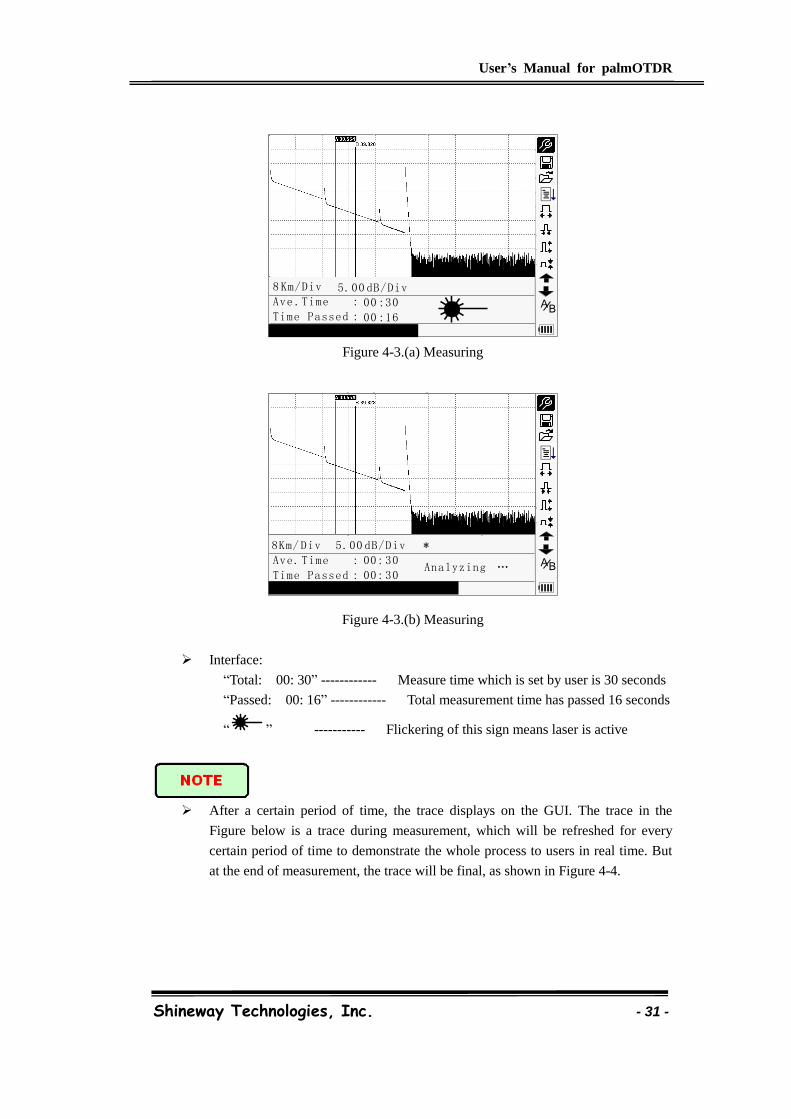
﹡8Km/ Div 5.00 dB/Div
00: 30
00: 30Analyzing …
Ave. Time :
Time Passed :BA
Figure 4-3.(b) Measuring
Interface:
“Total: 00: 30” ------------ Measure time which is set by user is 30 seconds
“Passed: 00: 16” ------------ Total measurement time has passed 16 seconds
“ ” ----------- Flickering of this sign means laser is active
After a certain period of time, the trace displays on the GUI. The trace in the
Figure below is a trace during measurement, which will be refreshed for every
certain period of time to demonstrate the whole process to users in real time. But
at the end of measurement, the trace will be final, as shown in Figure 4-4.
User’s Manual for palmOTDR
Shineway Technologies, Inc. - 32 -
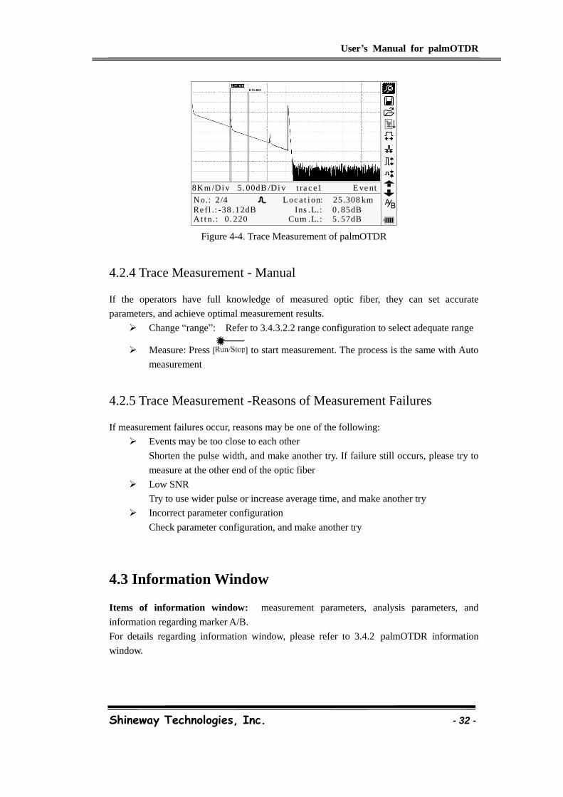
No.: 2/4
At t n.: 0. 220
L oc a t i on: 25.308 km
Re fl .: -38 .12dB Ins .L.: 0. 85dBCum .L.: 5. 57dB
8Km /Di v 5. 00dB /Di v t ra c e1 E ve nt
BA
Figure 4-4. Trace Measurement of palmOTDR
4.2.4 Trace Measurement - Manual
If the operators have full knowledge of measured optic fiber, they can set accurate
parameters, and achieve optimal measurement results.
Change “range”: Refer to 3.4.3.2.2 range configuration to select adequate range
Measure: Press [ ] to start measurement. The process is the same with Auto
measurement
4.2.5 Trace Measurement -Reasons of Measurement Failures
If measurement failures occur, reasons may be one of the following:
Events may be too close to each other
Shorten the pulse width, and make another try. If failure still occurs, please try to
measure at the other end of the optic fiber
Low SNR
Try to use wider pulse or increase average time, and make another try
Incorrect parameter configuration
Check parameter configuration, and make another try
4.3 Information Window
Items of information window: measurement parameters, analysis parameters, and
information regarding marker A/B.
For details regarding information window, please refer to 3.4.2 palmOTDR information
window.
User’s Manual for palmOTDR
Shineway Technologies, Inc. - 33 -
4.3.1 Switch between Information Window Items
Under GUI of Figure 4-4., press [ ] and the items of information window will display in
circulation: measurement parameter→ analysis information→ Event list→ information of
marker A/B →fiber →measurement parameter.
4.3.2 Review Event List
Under GUI of Figure 4-4, press [ ], items in information window will switch to event list
information.
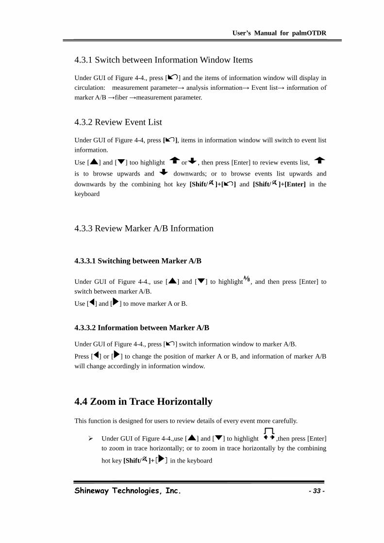
Use [ ] and [ ] too highlight or , then press [Enter] to review events list,
is to browse upwards and downwards; or to browse events list upwards and
downwards by the combining hot key [Shift/ ]+[ ] and [Shift/ ]+[Enter] in the
keyboard
4.3.3 Review Marker A/B Information
4.3.3.1 Switching between Marker A/B
Under GUI of Figure 4-4., use [ ] and [ ] to highlight BA, and then press [Enter] to
switch between marker A/B.
Use [ ] and [ ] to move marker A or B.
4.3.3.2 Information between Marker A/B
Under GUI of Figure 4-4., press [ ] switch information window to marker A/B.
Press [ ] or [ ] to change the position of marker A or B, and information of marker A/B
will change accordingly in information window.
4.4 Zoom in Trace Horizontally
This function is designed for users to review details of every event more carefully.
Under GUI of Figure 4-4.,use [ ] and [ ] to highlight ,then press [Enter]
to zoom in trace horizontally; or to zoom in trace horizontally by the combining
hot key [Shift/ ]+[ ] in the keyboard

User’s Manual for palmOTDR
Shineway Technologies, Inc. - 34 -
Press [ ] or [ ] to move marker to the event point to be observed
To examine information of event point ,please according to”4.3.3.1 Switching
between Marker A/B”
4.5 Zoom out Trace Horizontally
This function is to zoom out trace horizontally.
Under GUI of Figure 4-4., use [ ] and [ ] to highlight , and press [Enter] to zoom
out trace. or to zoom out trace horizontally by the combining hot key [Shift/ ]+[ ] in the
keyboard.
4.6 Zoom in Trace Vertically
This function is designed for users to review event points more carefully.
Under GUI of 4-4, press [ ] and [ ] to highlight , then press [Enter] to
zoom in vertically; or to zoom in trace vertically by the combining hot key
[Shift/ ]+[ ] in the keyboard
Use [ ] and [ ] to mover marker to event point to be observed
For details, please refer to 6.3.3.1 switching between Marker A/B
4.7 Zoom out Trace Vertically
This function is designed to zoom out trace vertically.
Under GUI of Figure 4-4, press [ ] and [ ] to highlight , then press [Enter]
to zoom out trace vertically. or to zoom out trace vertically by the combining hot
key [Shift/ ]+ [ ] in the keyboard.
4.8 Re-analyze the trace
While the test result at a certain threshold is not good enough, it can be re-analyzed by this
function (to change the threshold). Please note that this function can be effective while the
OTDR is disconnected from the fiber.
Under parameter configuration menu, edit the threshold value you want, press
[ ] to exit parameter configuration menu, then press [ ] to re-analyze the
User’s Manual for palmOTDR
Shineway Technologies, Inc. - 35 -
trace.
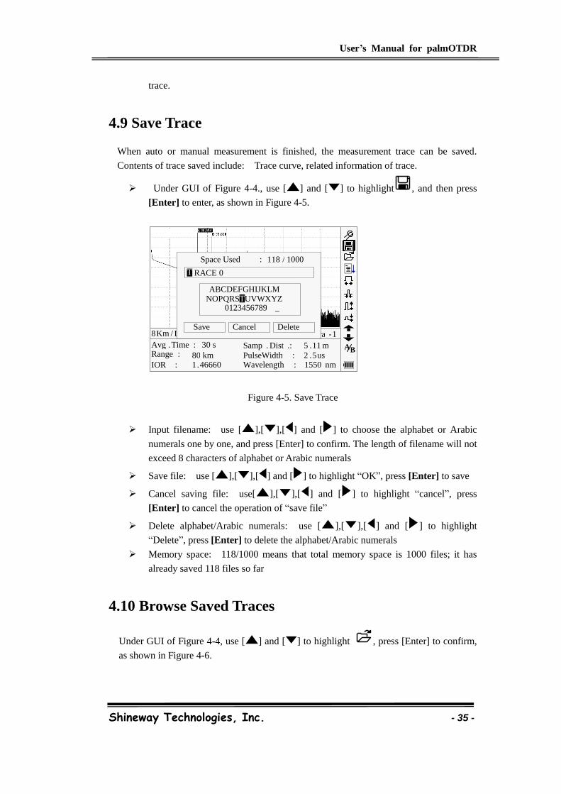
4.9 Save Trace
When auto or manual measurement is finished, the measurement trace can be saved.
Contents of trace saved include: Trace curve, related information of trace.
Under GUI of Figure 4-4., use [ ] and [ ] to highlight , and then press
[Enter] to enter, as shown in Figure 4-5.
Figure 4-5. Save Trace
Input filename: use [ ],[ ],[ ] and [ ] to choose the alphabet or Arabic
numerals one by one, and press [Enter] to confirm. The length of filename will not
exceed 8 characters of alphabet or Arabic numerals
Save file: use [ ],[ ],[ ] and [ ] to highlight “OK”, press [Enter] to save
Cancel saving file: use[ ],[ ],[ ] and [ ] to highlight “cancel”, press
[Enter] to cancel the operation of “save file”
Delete alphabet/Arabic numerals: use [ ],[ ],[ ] and [ ] to highlight
“Delete”, press [Enter] to delete the alphabet/Arabic numerals
Memory space: 118/1000 means that total memory space is 1000 files; it has
already saved 118 files so far
4.10 Browse Saved Traces
Under GUI of Figure 4-4, use [ ] and [ ] to highlight , press [Enter] to confirm,
as shown in Figure 4-6.
30 s 80 km 1 . 46660
2 . 5 us 1550 nm
Avg . Time : Range : IOR :
PulseWidth : Wavelength :
8 Km / Div 3 . 50 dB / Div trace 1 . trc Para - 1 Cancel
ABCDEFGHIJKLM NOPQRSTUVWXYZ
0123456789 _
Space Used : 118 / 1000
Save Delete
RACE 0 T
T
Samp . Dist .: 5 . 11 m B A
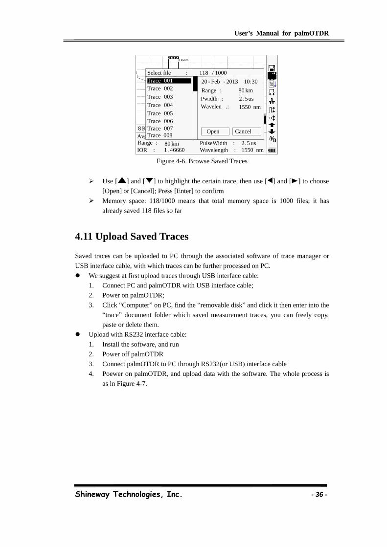
User’s Manual for palmOTDR
Shineway Technologies, Inc. - 36 -
Figure 4-6. Browse Saved Traces
Use [ ] and [ ] to highlight the certain trace, then use [ ] and [ ] to choose
[Open] or [Cancel]; Press [Enter] to confirm
Memory space: 118/1000 means that total memory space is 1000 files; it has
already saved 118 files so far
4.11 Upload Saved Traces
Saved traces can be uploaded to PC through the associated software of trace manager or
USB interface cable, with which traces can be further processed on PC.
We suggest at first upload traces through USB interface cable:
1. Connect PC and palmOTDR with USB interface cable;
2. Power on palmOTDR;
3. Click “Computer” on PC, find the “removable disk” and click it then enter into the
“trace” document folder which saved measurement traces, you can freely copy,
paste or delete them.
Upload with RS232 interface cable:
1. Install the software, and run
2. Power off palmOTDR
3. Connect palmOTDR to PC through RS232(or USB) interface cable
4. Poewer on palmOTDR, and upload data with the software. The whole process is
as in Figure 4-7.
30 s 80 km 1 . 46660
2 . 5 us 1550 nm
Avg . Time : Range : IOR :
PulseWidth : Wavelength :
8 Km / Div 3 . 50 dB / Div trace 1 . trc 15 : 20
Select file : 118 / 1000
Trace 001
Trace 002
Trace 003
Trace 004
Trace 005
Cancel Open
Trace 006 Trace 007 Trace 008
20 - Feb - 2013 10 : 30
Range : 80 km
Pwidth : 2 . 5 us
Wavelen .: 1550 nm
B A
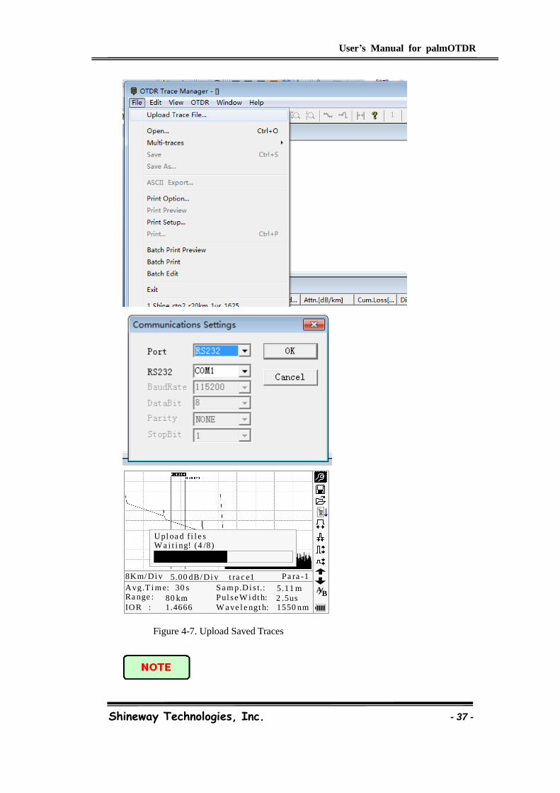
User’s Manual for palmOTDR
Shineway Technologies, Inc. - 37 -
30 s
80 km1.4666
2 .5us1550 nm
Avg.T i m e:Ra nge :
IOR :
Pul se W i dt h:
W a ve l e ngt h:
8Km/ Di v 5.00 dB/ Di v t ra c e1 Pa ra -1
Upl oa d f i l e sW a i t i ng! (4 /8)
BASa m p.Di s t.: 5.11 m
Figure 4-7. Upload Saved Traces
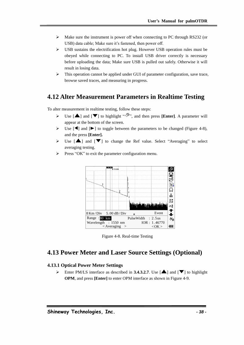
User’s Manual for palmOTDR
Shineway Technologies, Inc. - 38 -
Make sure the instrument is power off when connecting to PC through RS232 (or
USB) data cable; Make sure it’s fastened, then power off.
USB sustains the electrification hot plug. However USB operation rules must be
obeyed while connecting to PC. To install USB driver correctly is necessary
before uploading the data; Make sure USB is pulled out safely. Otherwise it will
result in losing data.
This operation cannot be applied under GUI of parameter configuration, save trace,
browse saved traces, and measuring in progress.
4.12 Alter Measurement Parameters in Realtime Testing
To alter measurement in realtime testing, follow these steps:
Use [ ] and [ ] to highlight “ ”, and then press [Enter]. A parameter will
appear at the bottom of the screen.
Use [ ] and [ ] to toggle between the parameters to be changed (Figure 4-8),
and the press [Enter].
Use [ ] and [ ] to change the Ref value. Select “Averaging” to select
averaging testing.
Press “OK” to exit the parameter configuration menu.
Figure 4-8. Real-time Testing
4.13 Power Meter and Laser Source Settings (Optional)
4.13.1 Optical Power Meter Settings
Enter PM/LS interface as described in 3.4.3.2.7. Use [ ] and [ ] to highlight
OPM, and press [Enter] to enter OPM interface as shown in Figure 4-9.
﹡ 8 Km / Div 5 . 00 dB / Div Range : Wavelength : 1550 nm
B A
Event
80 km PulseWidth : 2 . 5 us IOR : 1 . 46770
< Averaging > < OK >
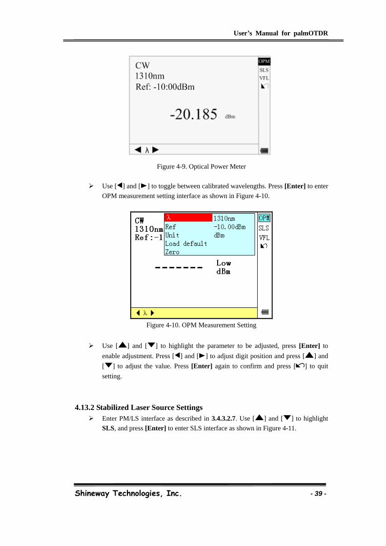
User’s Manual for palmOTDR
Shineway Technologies, Inc. - 39 -
Figure 4-9. Optical Power Meter
Use [ ] and [ ] to toggle between calibrated wavelengths. Press [Enter] to enter
OPM measurement setting interface as shown in Figure 4-10.
Figure 4-10. OPM Measurement Setting
Use [ ] and [ ] to highlight the parameter to be adjusted, press [Enter] to
enable adjustment. Press [ ] and [ ] to adjust digit position and press [ ] and
[ ] to adjust the value. Press [Enter] again to confirm and press [ ] to quit
setting.
4.13.2 Stabilized Laser Source Settings
Enter PM/LS interface as described in 3.4.3.2.7. Use [ ] and [ ] to highlight
SLS, and press [Enter] to enter SLS interface as shown in Figure 4-11.
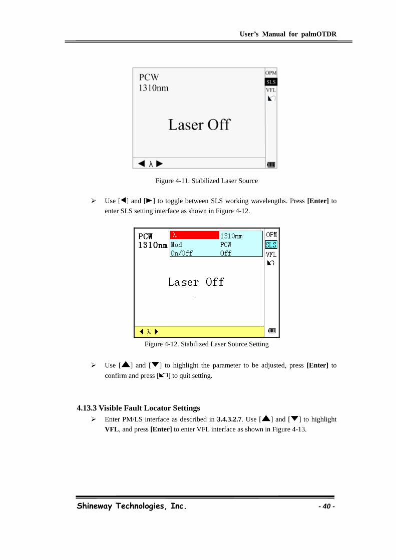
User’s Manual for palmOTDR
Shineway Technologies, Inc. - 40 -
Figure 4-11. Stabilized Laser Source
Use [ ] and [ ] to toggle between SLS working wavelengths. Press [Enter] to
enter SLS setting interface as shown in Figure 4-12.
Figure 4-12. Stabilized Laser Source Setting
Use [ ] and [ ] to highlight the parameter to be adjusted, press [Enter] to
confirm and press [ ] to quit setting.
4.13.3 Visible Fault Locator Settings
Enter PM/LS interface as described in 3.4.3.2.7. Use [ ] and [ ] to highlight
VFL, and press [Enter] to enter VFL interface as shown in Figure 4-13.
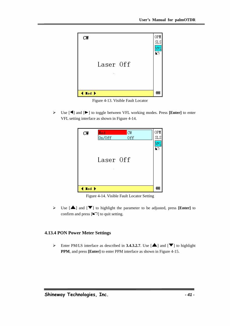
User’s Manual for palmOTDR
Shineway Technologies, Inc. - 41 -
Figure 4-13. Visible Fault Locator
Use [ ] and [ ] to toggle between VFL working modes. Press [Enter] to enter
VFL setting interface as shown in Figure 4-14.
Figure 4-14. Visible Fault Locator Setting
Use [ ] and [ ] to highlight the parameter to be adjusted, press [Enter] to
confirm and press [ ] to quit setting.
4.13.4 PON Power Meter Settings
Enter PM/LS interface as described in 3.4.3.2.7. Use [ ] and [ ] to highlight
PPM, and press [Enter] to enter PPM interface as shown in Figure 4-15.
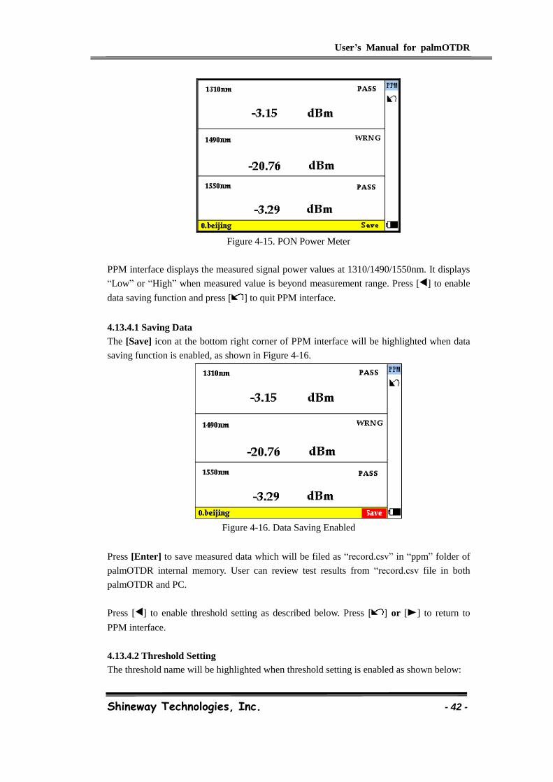
User’s Manual for palmOTDR
Shineway Technologies, Inc. - 42 -
Figure 4-15. PON Power Meter
PPM interface displays the measured signal power values at 1310/1490/1550nm. It displays
“Low” or “High” when measured value is beyond measurement range. Press [ ] to enable
data saving function and press [ ] to quit PPM interface.
4.13.4.1 Saving Data
The [Save] icon at the bottom right corner of PPM interface will be highlighted when data
saving function is enabled, as shown in Figure 4-16.
Figure 4-16. Data Saving Enabled
Press [Enter] to save measured data which will be filed as “record.csv” in “ppm” folder of
palmOTDR internal memory. User can review test results from “record.csv file in both
palmOTDR and PC.
Press [ ] to enable threshold setting as described below. Press [ ] or [ ] to return to
PPM interface.
4.13.4.2 Threshold Setting
The threshold name will be highlighted when threshold setting is enabled as shown below:
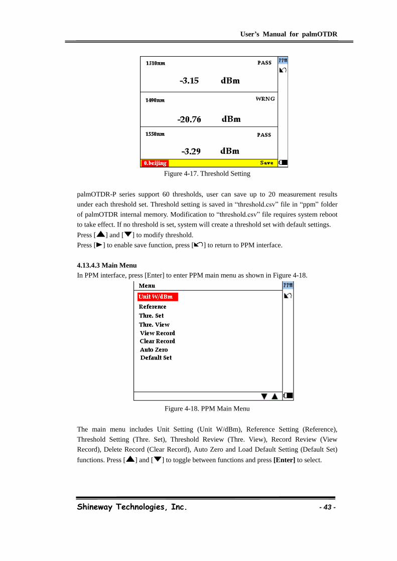
User’s Manual for palmOTDR
Shineway Technologies, Inc. - 43 -
Figure 4-17. Threshold Setting
palmOTDR-P series support 60 thresholds, user can save up to 20 measurement results
under each threshold set. Threshold setting is saved in “threshold.csv” file in “ppm” folder
of palmOTDR internal memory. Modification to “threshold.csv” file requires system reboot
to take effect. If no threshold is set, system will create a threshold set with default settings.
Press [ ] and [ ] to modify threshold.
Press [ ] to enable save function, press [ ] to return to PPM interface.
4.13.4.3 Main Menu
In PPM interface, press [Enter] to enter PPM main menu as shown in Figure 4-18.
Figure 4-18. PPM Main Menu
The main menu includes Unit Setting (Unit W/dBm), Reference Setting (Reference),
Threshold Setting (Thre. Set), Threshold Review (Thre. View), Record Review (View
Record), Delete Record (Clear Record), Auto Zero and Load Default Setting (Default Set)
functions. Press [ ] and [ ] to toggle between functions and press [Enter] to select.
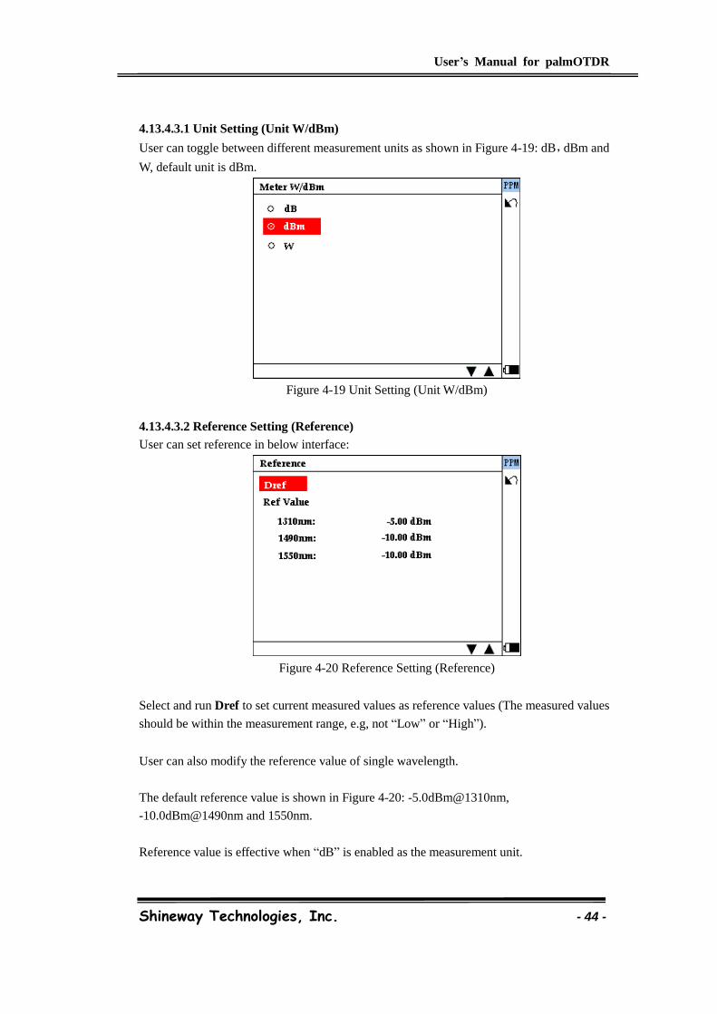
User’s Manual for palmOTDR
Shineway Technologies, Inc. - 44 -
4.13.4.3.1 Unit Setting (Unit W/dBm)
User can toggle between different measurement units as shown in Figure 4-19: dB,dBm and
W, default unit is dBm.
Figure 4-19 Unit Setting (Unit W/dBm)
4.13.4.3.2 Reference Setting (Reference)
User can set reference in below interface:
Figure 4-20 Reference Setting (Reference)
Select and run Dref to set current measured values as reference values (The measured values
should be within the measurement range, e.g, not “Low” or “High”).
User can also modify the reference value of single wavelength.
The default reference value is shown in Figure 4-20: -5.0dBm@1310nm,
-10.0dBm@1490nm and 1550nm.
Reference value is effective when “dB” is enabled as the measurement unit.

User’s Manual for palmOTDR
Shineway Technologies, Inc. - 45 -
4.13.4.3.3 Threshold Setting (Thre. Set)
User can enable/disable threshold function by selecting and running “Thre. Set”. When such
function is enabled, PPM will compare measured values with threshold settings and display
PASS, FAIL or WRNG (Warning) accordingly. Threshold setting is on by default.
4.13.4.3.4 Threshold Review (Thre. View)
User can check threshold settings by selecting and running Thre. View, please select the
threshold set (Test Station) to review.
Figure 4-21 Reference Setting (Reference)
Select the threshold set(Test Station) and press [Enter] to review the threshold
settings:
Switch the wavelength by [ ] and [ ].
4.13.4.3.5 Record Review (View Record)
User can check the saved record by selecting and running View Record, please select
the test station to review.
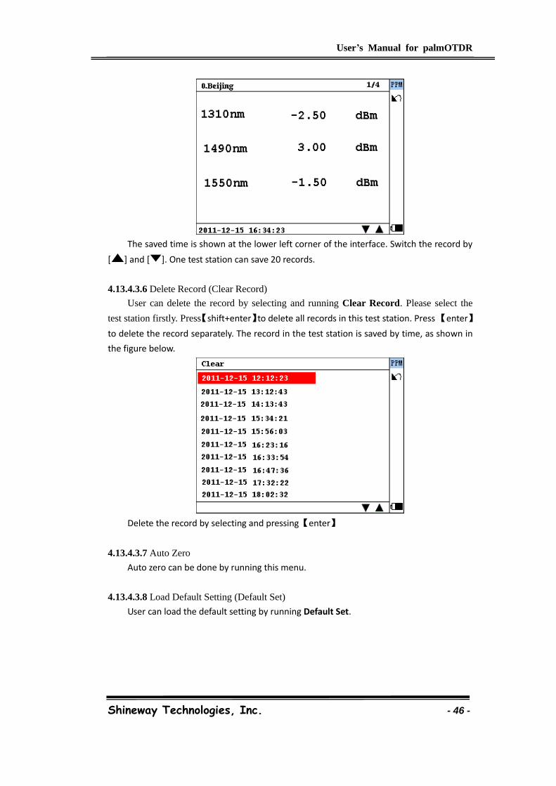
User’s Manual for palmOTDR
Shineway Technologies, Inc. - 46 -
The saved time is shown at the lower left corner of the interface. Switch the record by
[ ] and [ ]. One test station can save 20 records.
4.13.4.3.6 Delete Record (Clear Record)
User can delete the record by selecting and running Clear Record. Please select the
test station firstly. Press【shift+enter】to delete all records in this test station. Press 【enter】
to delete the record separately. The record in the test station is saved by time, as shown in
the figure below.
Delete the record by selecting and pressing【enter】
4.13.4.3.7 Auto Zero
Auto zero can be done by running this menu.
4.13.4.3.8 Load Default Setting (Default Set)
User can load the default setting by running Default Set.
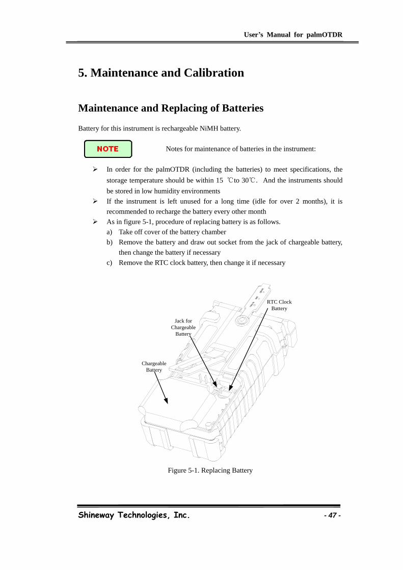
User’s Manual for palmOTDR
Shineway Technologies, Inc. - 47 -
5. Maintenance and Calibration
Maintenance and Replacing of Batteries
Battery for this instrument is rechargeable NiMH battery.
Notes for maintenance of batteries in the instrument:
In order for the palmOTDR (including the batteries) to meet specifications, the
storage temperature should be within 15 ℃to 30℃. And the instruments should
be stored in low humidity environments
If the instrument is left unused for a long time (idle for over 2 months), it is
recommended to recharge the battery every other month
As in figure 5-1, procedure of replacing battery is as follows.
a) Take off cover of the battery chamber
b) Remove the battery and draw out socket from the jack of chargeable battery,
then change the battery if necessary
c) Remove the RTC clock battery, then change it if necessary
RTC Clock
Battery
Jack for
Chargeable
Battery
Chargeable
Battery
Figure 5-1. Replacing Battery
User’s Manual for palmOTDR
Shineway Technologies, Inc. - 48 -
Cleaning of Interfaces
Interfaces must be kept clean. Special alcohol may be used to clean optic output. Always
replace protective dust caps when the unit is not being used, and keep the protective dust
caps clean.
In addition, flanges must be kept clean periodically,
Effects of Cleaning Interfaces and Connectors
The diameter of optic core is 9um, and diameter of dust and other particulates ranges from
1/100 to 1/1/10 um. Comparatively speaking, the size of dust and other particulates can
cover part of optic end and therefore degrade the performance of the instrument.
In addition, power density may burn dust into optic fiber and induce further damage(for
example, 0dBm optic power may produce about16000000W/m*m power density in single
mode fiber). In this case, measurement will be inaccurate and irreversible.
Safety instructions to be followed before cleaning
a) Make sure the instrument is power off when cleaning
b) Any operations contradict to the instructions may result in dangerous laser
injuries
c) Make sure laser source is off, when clean any optic connectors
d) When the instrument is in operation, please always avoid looking directly
into optic output. Although laser radiation is invisible, it may do serious
injury to eyesight
e) Be cautious of electric shock and make sure AC power is disconnected with
the instrument before cleaning. Always use dry or moistest soft cloth to clean
the outside of the instrument, and never clean the inside
f) Please do not add any accessory to optic instrument or adjust the instrument
at discretion
g) For maintenance, always go to qualified or certified professionals
Tools for Cleaning Interfaces and Connectors
a) Optic fiber cleaner (for cleaning of optic connectors)
b) Optic fiber cleaning rod (for cleaning of optic outputs)
c) Optic fiber cleaning tissue (for cleaning optic interfaces)
d) Isopropyl alcohol
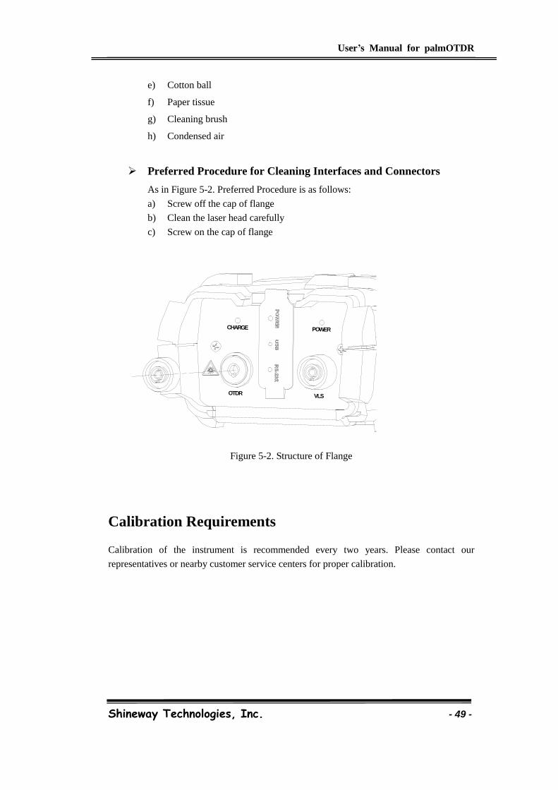
User’s Manual for palmOTDR
Shineway Technologies, Inc. - 49 -
e) Cotton ball
f) Paper tissue
g) Cleaning brush
h) Condensed air
Preferred Procedure for Cleaning Interfaces and Connectors
As in Figure 5-2. Preferred Procedure is as follows:
a) Screw off the cap of flange
b) Clean the laser head carefully
c) Screw on the cap of flange
VLSOTDR
CHARGE POWER
Figure 5-2. Structure of Flange
Calibration Requirements
Calibration of the instrument is recommended every two years. Please contact our
representatives or nearby customer service centers for proper calibration.
Shineway Technologies, Inc. - 50 -
6. Warranty Information
Terms of Warranty
All ShinewayTech products are warranted against defective material and workmanship for a
period of one (1) year from the date of shipment to the original customer. Any product found to be
defective within the warranty period would be repaired or replaced by Shineway Technologies Inc.
free of charge.
In no case will Shineway Technologies, Inc. liabilities exceed the original purchase price of the
product.
Exclusions
The warranty on your equipment shall not apply to defects resulting from the following:
Unauthorized repair or modification
Misuse, negligence, or accident
Shineway Technologies, Inc. reserves the right to make changes to any of its products at any time
without having to replace or change previously purchased units.
Warranty Registration
A warranty registration card is included with the original shipment of equipment. Please take a
few moments to fill out the card and mail or fax it to the local Customer Service Center of
Shineway Technologies, Inc. to ensure proper initiation of your warranty term and scope of your
warranty.
Returning Instruments
To return instrument for reasons of yearly calibration or other, please contact the local Customer
Service Center of Shineway Technologies, Inc. to obtain additional information and a RMA#
(Return Materials Authorization number). And describe briefly reasons for the return of the
equipment, to allow us offer you more efficient service.
To return the instrument in the case of repair, calibration or other
maintenance, please note the following:

Shineway Technologies, Inc. - 51 -
Be sure to pack the instrument with soft cushion like Polyethylene, so as to protect the
shell of the instrument.
Please use the original hard packing box. If use other packing material, please ensure at
least 3 cm soft material around the instrument.
Be sure to correctly fill out and return the warranty registration card, which should
include the following information: company name, postal address, contact, phone
number, email address and problem description.
Be sure to seal the packing box with exclusive tape.
Be sure to ship to your representative or the agent of the Company in a reliable way.
Contacting Customer Service
Please check our web site (www.shinewaytech.com) for updates to this manual and additional
application information. If you need technical or sales support, please contact local Shineway
Technologies Customer Service.
Shineway Technologies (China), Inc.: Address: Fl.7, Zhongtai Plaza, No.3 Shuangqing Rd, Haidian District, Beijing, China Postal code: 100085 Tel: +86-10-62953388 Fax: +86-10-62958572 Email: [email protected] WEB: www.shinewaytech.com

Shineway Technologies, Inc. - 52 -
THANK YOU FOR CHOOSING
SHINEWAY TECHNOLOGIES!
DOC. P/N: MAN-pOTDR.V110.10/10