Embed Size (px)
Citation preview
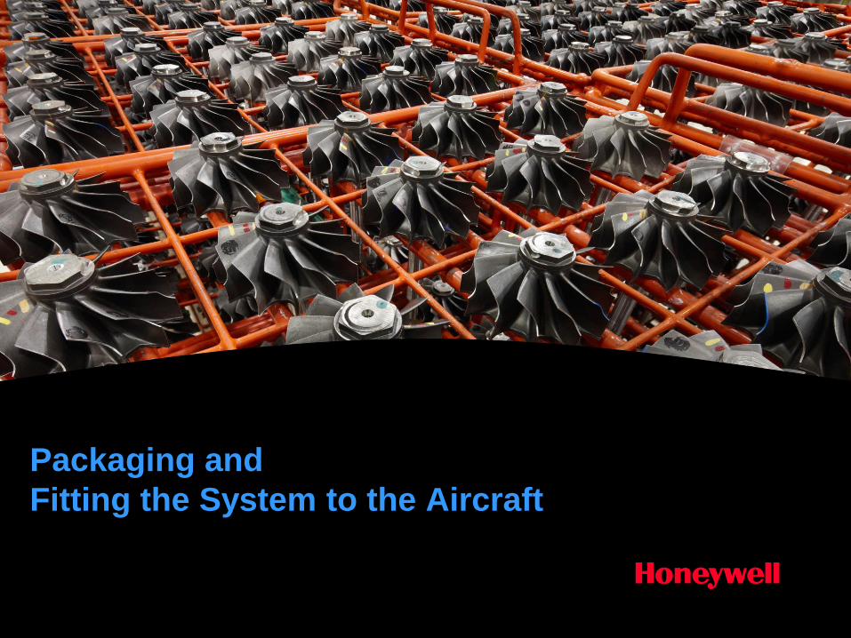
Packaging and
Fitting the System to the Aircraft
Honeywell Proprietary
Honeywell.com
2
Document control number
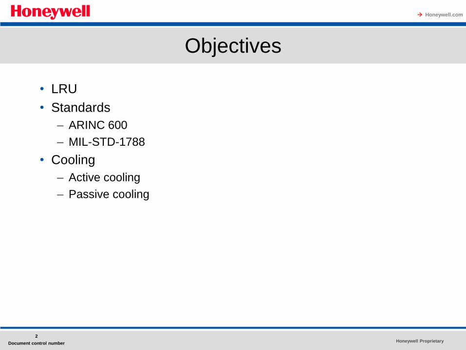
Objectives
• LRU
• Standards
– ARINC 600
– MIL-STD-1788
• Cooling
– Active cooling
– Passive cooling
Honeywell Proprietary
Honeywell.com
3
Document control number
Packaging and Fitting the system to the aircraft
One of the toughest parts of building a good digital avionics system is
fitting the system into the aircraft.
• The most common image of avionics is the familiar "black
box," more formally known as an LRU.
• Every digital avionics system usually ends up packaged in one
or more LRUs.
• Descriptions of standardized LRUs for both civil and military
avionics are given in this presentation.
These standard LRU designs offer many advantages to both the
designer and the operator in the form of ◦ interchangeability,
◦ easier maintenance
Honeywell Proprietary
Honeywell.com
4
Document control number
Packaging and Fitting the system to the aircraft
• In the opinion of many experts, keeping the
avionics cool is the secret to highly reliable
operation.
– This presentation discusses some avionics cooling
methods and LRU design techniques that reduce
thermal stress on the components.
• The final section of this presentation interprets
interfaces in two parts:
–what the aircraft provides to the avionics and
–what the avionics impacts on the aircraft are.
Honeywell Proprietary
Honeywell.com
5
Document control number
Packaging and Fitting the system to the aircraft
• The avionics units have to be packaged in ATR or Austin Trumbull Racking
• ARINC 600 for Civil Aircraft • MIL-STD-1788 for Military Aircraft • These have some commonality, as many
manufacturers make both types • ARINC 600 establishes the form factor, external
design, and environmental interfaces with the aircraft.
• It facilitates exchange of LRU manufactured by one company to perform one function with one made by another vendor.
• (ARINC 700 Form, Fit, Function)
Honeywell Proprietary
Honeywell.com
6
Document control number
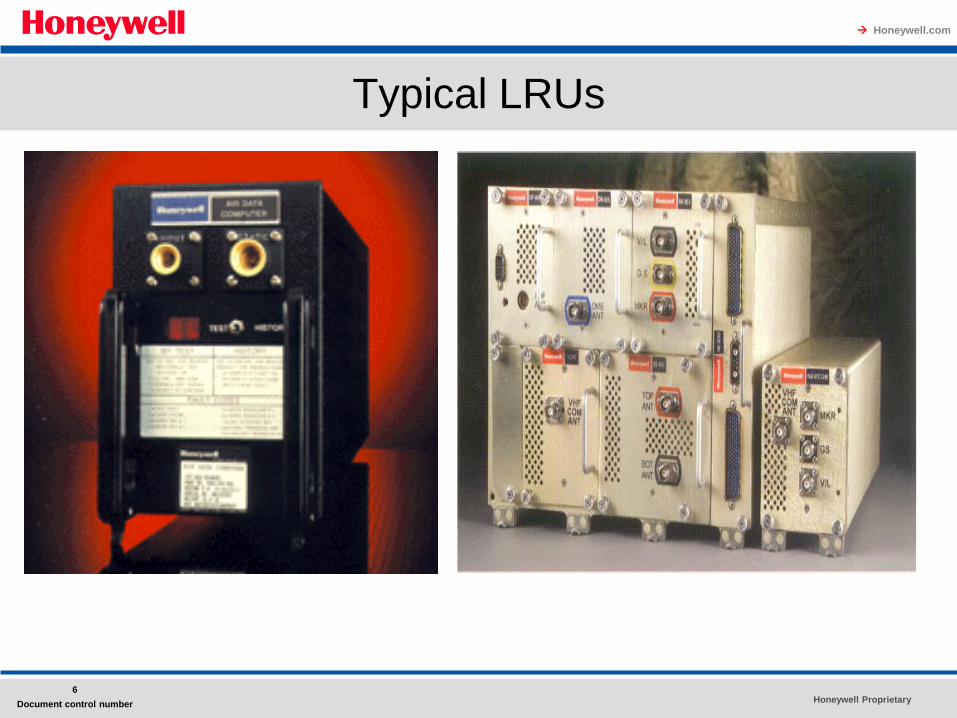
Typical LRUs
Honeywell Proprietary
Honeywell.com
7
Document control number
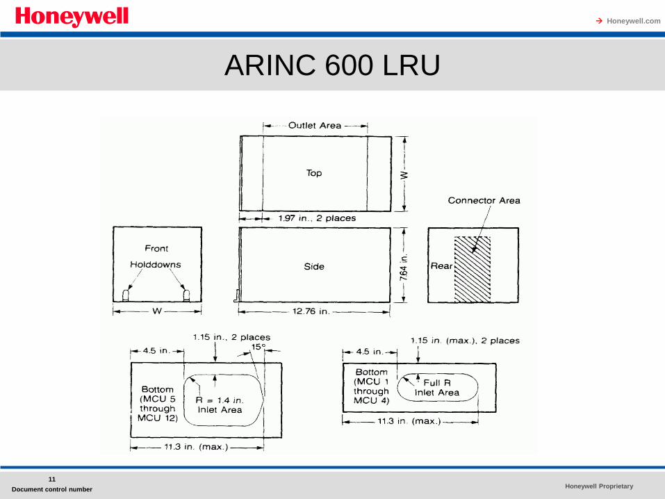
ARINC 600
• All LRUs are 194mm(7.64”) high, 324mm (12.76”) length
which is the same as ARINC 404 ATR short case
• MCU as the basic width of LRU
• 8 MCU = one ATR as defined by ARINC 404
• ARINC 404 established Air Transport Racking (ATR), but on April 11,
1967, the Airlines Electronic Engineering Committee corrected ARINC
404 so that ATR Came to mean Austin Trumbull radio as was originally
intended to honor the founder of the concept of standardized packaging
and interfaces for air transport avionics.
• Width = (Nx33)-8 mm or
Width = (Nx1.30) - 0.32 inches,
where N = number of MCUs
• Electrical Connections are located at the back panel
• Cooling Air, if provided, flows from bottom to top
Honeywell Proprietary
Honeywell.com
8
Document control number
ARINC 600
• Electrical power must meet the requirements of RTCA(Radio Technical
Commission for Aeronautics) document DO160E or its equivalent
EUROCAE document ED-14.
• Allowable power dissipation is a function of the LRU width.
• For LRUs without forced air cooling, power is limited to (5 + 2.5N)
W.
• Thus, for a one-MCU-wide LRU without forced air cooling, power
dissipation is limited to 7.5 W and
for a five-MCU-wide LRU to 17.5 W.
Honeywell Proprietary
Honeywell.com
9
Document control number
ARINC 600
For LRUs with forced air cooling, power dissipation is much higher
and can reach 25 W/MCU.
Regardless of the allowable power dissipation, the exterior vertical
surfaces of the LRU must not exceed 60°C (140°F) average.
The temperature of cooling air for continuous operation can range from
-15°C (5°F) to 55°C (131°F).
The air must not contain particles larger than 400 micrometers, or μm
(0.016 in).
Honeywell Proprietary
Honeywell.com
10
Document control number
ARINC 600
Cooling air openings, if used, are on the top and bottom of the LRU.
The weight of an ARINC 600 LRU is limited to 2.5 kg (5.5 lb)/MCU, not
to exceed 20 kg (44 Ib).
Thus, a four-MCU-wide LRU could weigh up to 10 kg (22 Ib) and a ten-
MCU-wide LRU, up to 20 kg (44 lb).
ARINC 600 has been adapted, with some changes, for use on military
aircraft as DOD-STD-1788 Avionics Interface Design Standard.
Honeywell Proprietary
Honeywell.com
11
Document control number
ARINC 600 LRU
Honeywell Proprietary
Honeywell.com
12
Document control number
Military Packaging Standards
MIL-STD-1788 Avionics Interface Design Standard establishes the form
factor, mounting, and environmental operating conditions for avionics to
be installed in the avionics bay of large military aircraft.
This standard is based on ARINC 600 and its predecessor, ARINC 404,
and they share many similarities.
Military avionics designers are required to use 1788 wherever possible
to achieve the reliability, maintainability, and life cycle cost benefits
promised from its application.
Like its civil predecessor, DOD-STD-1788 Avionics Interface Design
Standard establishes standard LRU case dimensions.
Honeywell Proprietary
Honeywell.com
13
Document control number
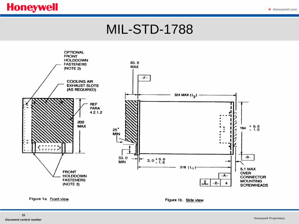
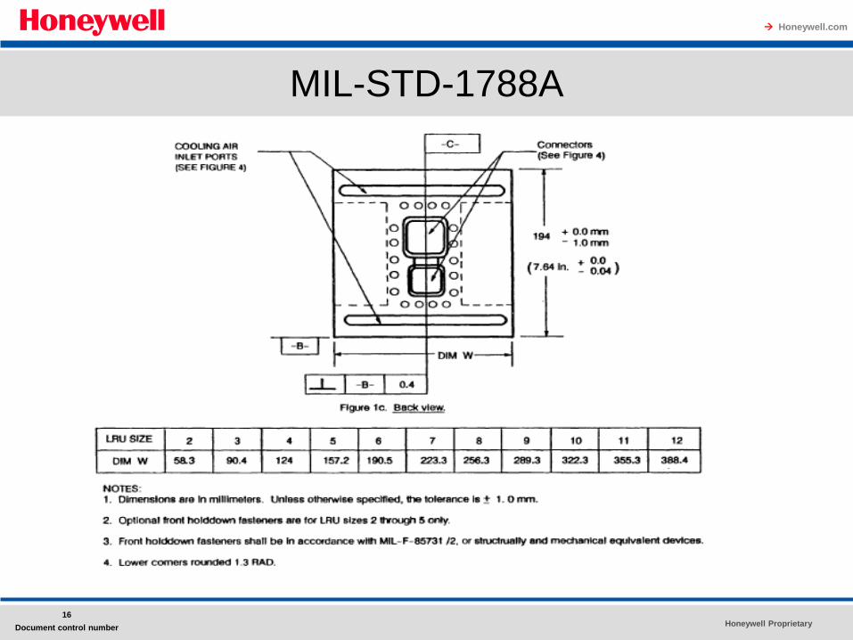
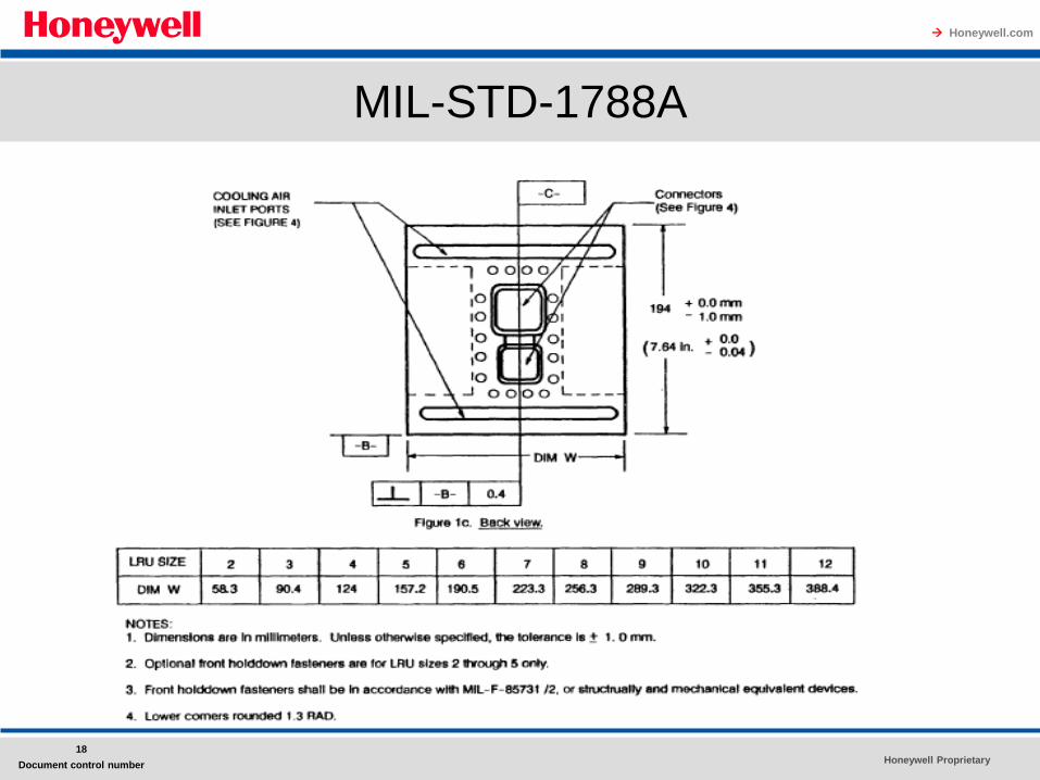
Military Packaging Standards
• All cases have a
– standard height of 194 mm (7.64 in) and
– a depth of 324 mm (12.76 in).
• MIL-STD-1788 describes the width of an LRU by a size number, N.
• The actual width of an LRU is determined by the formula
W = (N x 33) - 8.0 mm
or
W = (N X 1.30) - 0.32 in
where W=width and N = LRU size number.
• The rack space required in the avionics bay by an LRU is simply N x 33
mm (or N x 1.30 in).
Honeywell Proprietary
Honeywell.com
14
Document control number
Military Packaging Standards
Long-standing terms used to describe the dimensions of civil avionics LRUs are: ◦ MCU, as established by ARINC 600 Air Transport Avionics Equipment Interfaces,
and
◦ Austin Trumbull radio (ATR), as established in ARINC 404 Air Transport Equipment Cases and Racking.
The size number, N, of a 1788 LRU matches the width of a civil LRU in MCUs.
Thus, a 1788 LRU where N = 8 is identical in width to an ARINC 600 LRU where the width is 8 MCUs.
The depth of a 1788 LRU is the same as the depth of an ARINC 600 LRU.
Similar comparisons can be made between 1788 and ARINC 404.
A 1788 LRU where N = 8 is equal in width to a one-ATR-wide ARINC 404 LRU. The standard 1788 LRU depth of 324 mm (12.76 in) equals a short ATR case and an alternate depth of 502 mm (19.76 in) equals a long ATR case.
Honeywell Proprietary
Honeywell.com
15
Document control number
MIL-STD-1788
Honeywell Proprietary
Honeywell.com
16
Document control number
MIL-STD-1788A
Honeywell Proprietary
Honeywell.com
17
Document control number
MIL-STD-1788A
Honeywell Proprietary
Honeywell.com
18
Document control number
MIL-STD-1788A
Honeywell Proprietary
Honeywell.com
19
Document control number
MIL-STD-1788A
Honeywell Proprietary
Honeywell.com
20
Document control number
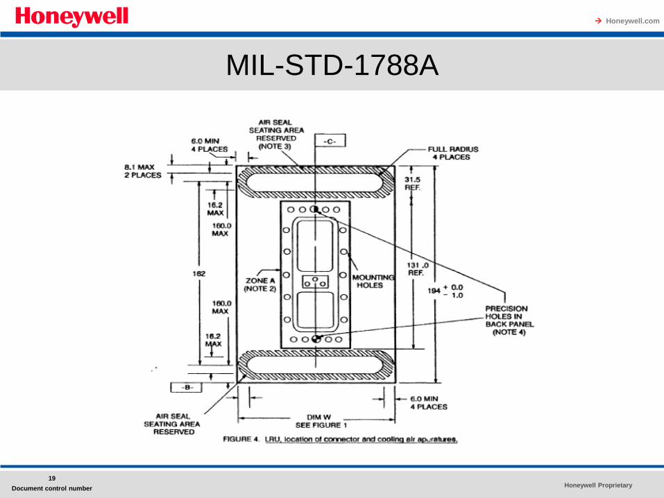
Military Packaging Standards
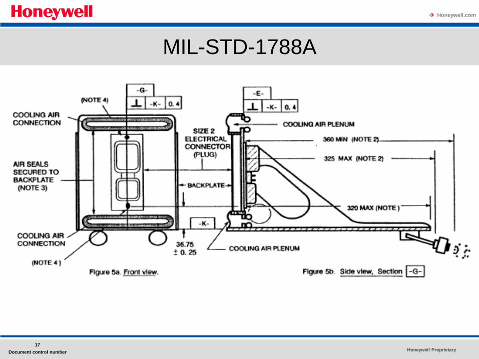
• The rear panel has cooling air inlets at the top and bottom and
also contains the electrical connector(s).
• An alternate case design, referred to as the low-profile tray, but
never discussed further in the standard, limits the case height to
170 mm (6.7 in) and places the cooling air inlets on the side of
the rear panel.
• For either case design, the cooling air exits the LRU through slots
in the front panel.
• However, if a closed cooling system is used, there are no front
openings; the rear panel top slot is the air inlet and the bottom
slot is the return.
• DOD-STD-1788 goes beyond specifying the dimensions of an
LRU case to present many other important design
considerations.
Honeywell Proprietary
Honeywell.com
21
Document control number
Military Packaging Standards
They include constraints on the weight and cooling air consumption as a
function of the width of the LRU.
The weight is limited to 3.5 kg (7.71b)/N, not to exceed a maximum
of 27.5 kg (60.5 lb).
In other words, LRUs where N <= 8 cannot weigh more than 27.5 kg
(60.5 lb).
Power dissipation for LRUs with cooling air is limited to 125 W/N.
Thus, an LRU for which N = 2 can dissipate up to 250 W and an LRU for
which N =12 can dissipate up to 1500 W.
LRU power dissipation without cooling air is limited to 10 + 2.5 x (N - 2)
W.
Honeywell Proprietary
Honeywell.com
22
Document control number
Military Packaging Standards
• In designing the LRU, cooling air is not permitted to flow directly over
electronic component to keep it at normal operating temperatures.
• The maximum temperature of an LRU side panel is limited to 76°C
(169"F) to minimize radiative or convective heat transfer to adjacent
LRUs.
• MIL-STD- 1788 requires the LRU design to be
"thermally optimized within appropriate design constraints to minimize the
LRU life cycle cost (LCC) and optimize the LRU reliability (based on the
predicted reliabilities of the individual parts)."
• The results of the analysis should be used to optimize the location of
piece parts to improve their reliability.
Honeywell Proprietary
Honeywell.com
23
Document control number
Military Packaging Standards
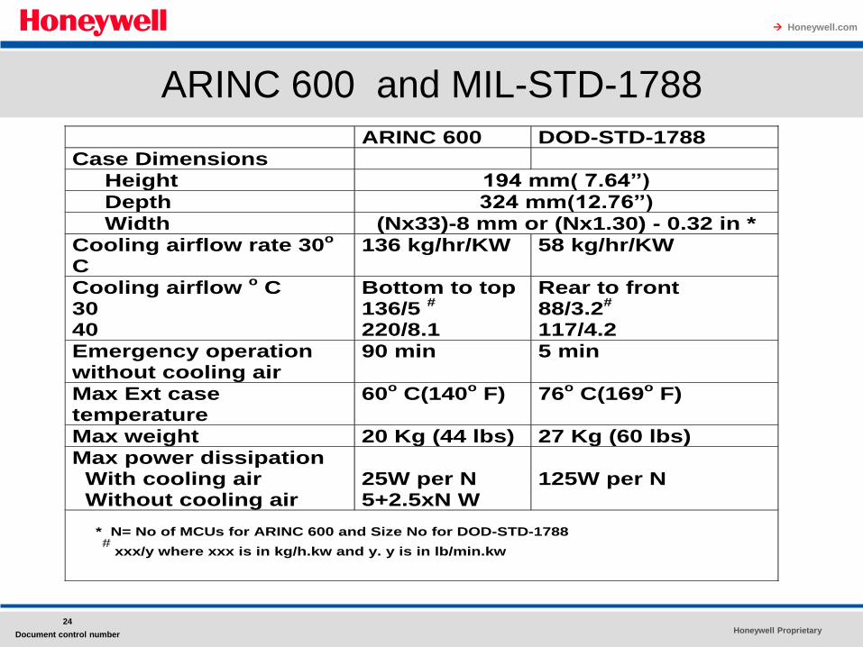
• A comparison of selected LRU parameters in ARINC 600 and MIL-STD-
1788 is given in Table.
• Note the relatively short operating time and substantially higher
maximum external case temperatures, without cooling air, for 1788 when
compared to ARINC 600.
• Thus, a source of cooling air that can be brought on line quickly is
required for military avionics.
Honeywell Proprietary
Honeywell.com
24
Document control number
ARINC 600 and MIL-STD-1788
ARINC 600 DOD-STD-1788
Case Dimensions
Height 194 mm( 7.64”)
Depth 324 mm(12.76”)
Width (Nx33)-8 mm or (Nx1.30) - 0.32 in *
Cooling airflow rate 30o
C 136 kg/hr/KW 58 kg/hr/KW
Cooling airflow o C
30 40
Bottom to top 136/5
#
220/8.1
Rear to front 88/3.2
#
117/4.2
Emergency operation without cooling air
90 min 5 min
Max Ext case temperature
60o C(140
o F)
76
o C(169
o F)
Max weight 20 Kg (44 lbs) 27 Kg (60 lbs)
Max power dissipation With cooling air Without cooling air
25W per N 5+2.5xN W
125W per N
* N= No of MCUs for ARINC 600 and Size No for DOD-STD-1788
#
xxx/y where xxx is in kg/h.kw and y. y is in lb/min.kw
Honeywell Proprietary
Honeywell.com
25
Document control number
Keeping the Avionics Cool
Conventional wisdom says that all electronics should be kept cool to achieve long life.
This is especially true for avionics, which are frequently inconvenient and expensive to maintain.
Earlier standards for interfacing the avionics with the aircraft, including the need for cooling air were discussed.
Focus on the benefits of keeping the avionics cool and offer design techniques to reduce thermal stress on the components.
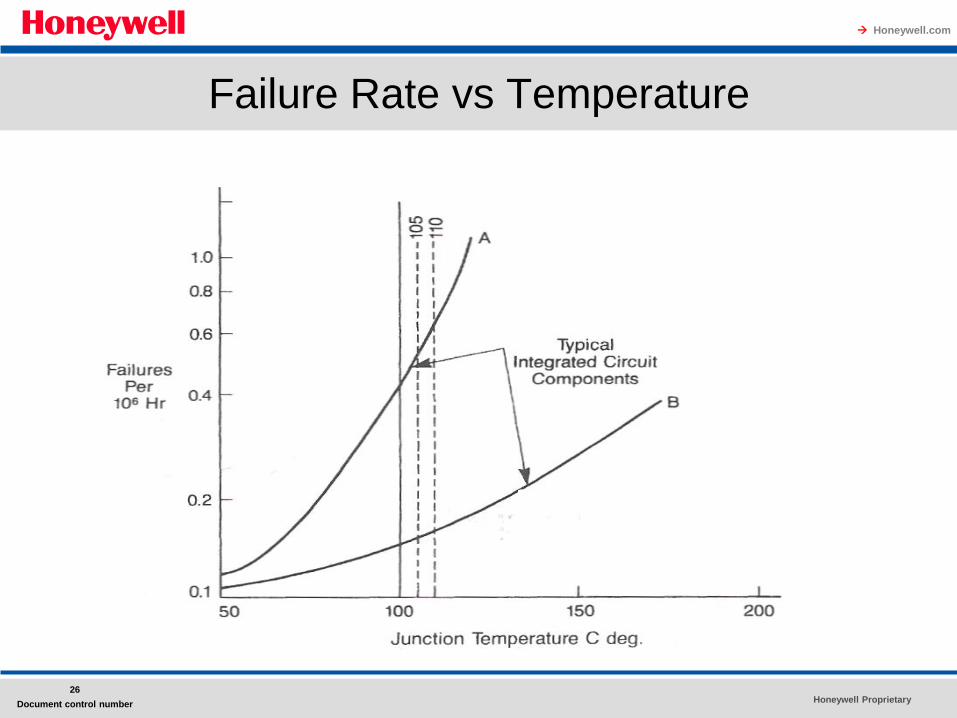
Many studies have demonstrated the value of reducing the temperature of electronic components to extend their lifetime.
Typical results from these studies are shown in Fig.
Honeywell Weather Radar Example
Honeywell Proprietary
Honeywell.com
26
Document control number
Failure Rate vs Temperature
Honeywell Proprietary
Honeywell.com
27
Document control number
Keeping the Avionics Cool
This figure shows that a 10oC (18oF) rise in Junction temperature increases the
device failure rate by about 50 percent for a component that matches curve A.
Raising the temperature of a component that matches curve B by 10°C (18oF)
raises the failure rate by only about 10 percent.
Passive cooling is a simple and obvious way to keep the avionics cool.
It has been used successfully in the past, but all modern avionics, especially in
densely packed military LRUs, have required active cooling, that is, air being
pulled over the avionics by fans.
Reexamination of passive cooling by the Boeing Commercial Airplane Co. has
shown that properly designed modules in a modular avionics architecture can
be adequately cooled by passive means.
Passive cooling saves weight and improves the overall reliability of the aircraft
since there is no avionics cooling equipment to fail.
Honeywell Proprietary
Honeywell.com
28
Document control number
Keeping the Avionics Cool
• ARINC 600 and MIL-STD-1788 recommend the use of cooling air
to keep the entire LRU at or below a selected operating
temperature limit.
• The more competent and astute designers go beyond these
recommendations and conduct analyses and tests to optimize the
location of components on circuit boards to ,substantially reduce
component and, therefore, LRU failure rates.
• The U.S. Air Force has established a Thermal Management
Control (TMC) program as Task 106 of MILSTD-785 Reliability
Program for Systems and Equipment Development and
Production.
• The objective of the TMC program is to allocate cooling capacity
at the system level to minimize LCC.
Honeywell Proprietary
Honeywell.com
29
Document control number
Keeping the Avionics Cool
• A subsidiary program, Electronic Equipment Thermal Management,
requires the avionics equipment design to be optimized for minimum
avionics LCC, not just to obtain a simple reliability goal.
• If an LRU contained a circuit board with two components, one of which
had a failure rate versus temperature that matched curve A in Fig. and
the other component matched curve B, emphasis should be placed on
reducing the operating temperature of the curve A type of component
since a reduction in temperature for it will yield the largest reduction in
the LRU failure rate.
• The most common ways to reduce the temperature of a component are
– to relocate the component on the circuit board or
– to relocate the circuit board within the LRU relative to the cooling air
Honeywell Proprietary
Honeywell.com
30
Document control number
Keeping the Avionics Cool
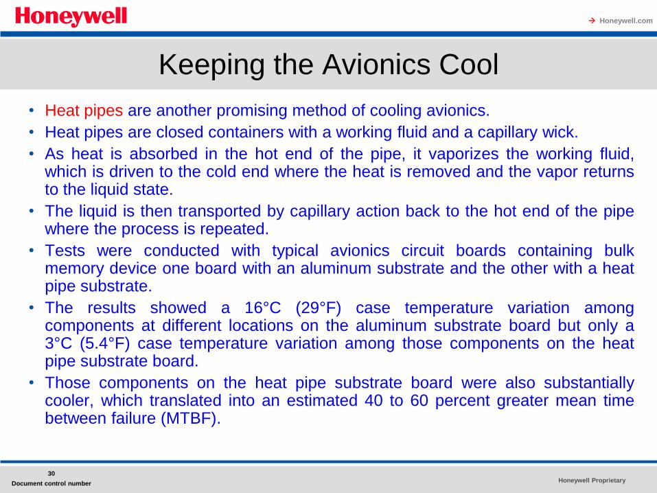
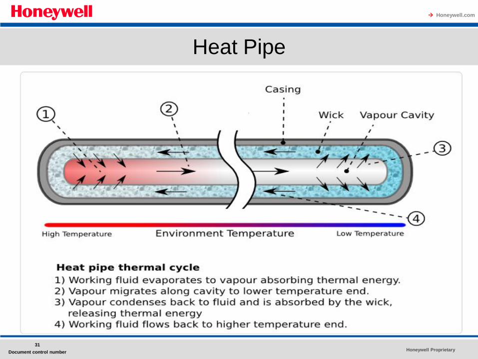
• Heat pipes are another promising method of cooling avionics.
• Heat pipes are closed containers with a working fluid and a capillary wick.
• As heat is absorbed in the hot end of the pipe, it vaporizes the working fluid, which is driven to the cold end where the heat is removed and the vapor returns to the liquid state.
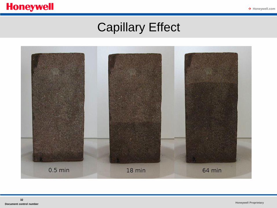
• The liquid is then transported by capillary action back to the hot end of the pipe where the process is repeated.
• Tests were conducted with typical avionics circuit boards containing bulk memory device one board with an aluminum substrate and the other with a heat pipe substrate.
• The results showed a 16°C (29°F) case temperature variation among components at different locations on the aluminum substrate board but only a 3°C (5.4°F) case temperature variation among those components on the heat pipe substrate board.
• Those components on the heat pipe substrate board were also substantially cooler, which translated into an estimated 40 to 60 percent greater mean time between failure (MTBF).
Honeywell Proprietary
Honeywell.com
31
Document control number
Heat Pipe
Honeywell Proprietary
Honeywell.com
32
Document control number
Capillary Effect
Honeywell Proprietary
Honeywell.com
33
Document control number
Keeping the Avionics Cool
• One major airline cools the entire avionics bay with a
separate onboard air conditioner any time the avionics
are operating on the ground and the bay temperature is
higher than 26°C (80°F).
• The MTBF of the LRUs is improved by approximately
60 percent.
Honeywell Proprietary
Honeywell.com
34
Document control number
Questions !!!