Embed Size (px)
Citation preview
P3 High Street Terang Electrical Incident 17 March 2018 Technical investigation report
Preface This technical investigation report has been prepared by Energy Safe Victoria (ESV) pursuant to the objectives, powers and functions conferred on it by The Electricity Safety Act 1998 (Act).
Specifically, these include, amongst other things, to investigate events or incidents, which have implications for electricity safety and to regulate, monitor and enforce the prevention and mitigation of bushfires that arise out of incidents involving electric lines or electrical installations and to monitor and enforce compliance with this Act and the regulations.
Energy Safe Victoria
Technical investigation report Page 3
Contents
Summary ................................................................................................................................................. 5
Report structure ................................................................................................................................... 6
Introduction ............................................................................................................................................. 7
Scope .................................................................................................................................................. 7 Objectives ............................................................................................................................................ 7 Methodology ........................................................................................................................................ 8 Background ......................................................................................................................................... 8 Declarations .......................................................................................................................................10 Investigation sequence of events ......................................................................................................12 Site plan .............................................................................................................................................12
Technical investigation ........................................................................................................................14
Site plan post-event ...........................................................................................................................14 Asset evidence ..................................................................................................................................15 Asset information ...............................................................................................................................19 Network asset inspections .................................................................................................................21 Operations records ............................................................................................................................22 Prevailing weather information ..........................................................................................................23
Findings and conclusions ...................................................................................................................25
The source of the Terang-Cobden Road fire ....................................................................................25 Circuit breaker operations .................................................................................................................25 Conductor clearances .......................................................................................................................25 Construction to standards .................................................................................................................25 The network asset inspection process ..............................................................................................26
Appendix A – Weather Observations .................................................................................................27
Energy Safe Victoria
Page 4 P3 High Street Terang Electrical Incident 17 March 2018
Figures
Figure 1: the Terang-Cobden Road fire ignition incident location ........................................................... 9
Figure 2: the extent of the Terang-Cobden Road fire (burnt land) .......................................................... 9 Figure 3: upper and lower P3 22kV circuit layouts ................................................................................ 10
Figure 4: GIS incident site area map ..................................................................................................... 10
Figure 5: the TRG Central 22kV electrical system diagram and incident location ................................ 11
Figure 6: site plan pre-event .................................................................................................................. 13
Figure 7: site plan post-event ................................................................................................................ 15
Figure 8: video stills showing the range of conductor movement (horizontal and vertical) ................... 16 Figure 9: P3 22kV conductor clash damage (position 1, 2 and 3) ........................................................ 16
Figure 10: clearances between the upper and lower P3 22kV conductors ........................................... 18
Figure 11: existing crossarm condition .................................................................................................. 19
Figure 12: conductor clearances recorded on 19 March 2018 before and after repair ......................... 20
Figure 13: Terang 004 feeder protection equipment operation information .......................................... 23
Figure 14: excerpt from the Warrnambool weather record for March 2018 .......................................... 23 Figure 15: excerpt from the Mortlake weather record for March 2018 .................................................. 23
Energy Safe Victoria
Technical investigation report Page 5
Summary On 17 March 2018, at approximately 20:49 Australian Eastern Standard Time1 (AEST), a high wind event passing though Victoria’s South West Region caused a fault on the electrical network and a fire in the Terang area that resulted in significant property damage.
The fire originated at or close to the location of Pole 3 (P3) on Powercor Australia Limited’s distribution network on the 22 kilovolt (kV) Terang 004 feeder (TRG 004), which attaches to a pole line that also carries the Terang to Warrnambool No.2 66kV line, near the intersection of Peterborough Road and High Street, Terang.
Energy Safe Victoria’s (ESV) technical investigation has established the following:
• there was evidence of arcing damage to the P3 22kV overhead conductors • on 17 March 2018
– the closest weather stations to the ignition site recorded north-westerly wind gusts of up to 104 kilometres per hour at or around 20:00 AEST
– four short circuit events occurred on the TRG 004 line between 20:45 and 20:49 AEST. These short circuit events collectively involved all three electrical phases, which is consistent with the damage to the P3 22kV conductors
– the TRG 004 circuit breaker operated four times to clear the four short circuit events – on a Code Red day the TRG 004 circuit breaker would have operated for the first short
circuit event and locked out
• the electrical clearances (distances) between the:
– upper and lower P3 22kV conductors were not constructed to Australian Standard (AS/NZS 7000:2016) or the Powercor Australia Limited Distribution Construction Standard (DC161)
– 22kV conductors and the ground were not constructed to the Australian Standard (AS/NZS 7000:2016) or the Powercor Australia Limited Technical Standard (DC111)
• Powercor Australia Limited has records of inspection involving P3 and other network assets in the vicinity and no instances of out-of-specification conductor or ground clearances were noted
• The Powercor asset management plan requires inspectors to check for non-compliant ground clearance and “out of sag” conductors
• The asset management plan2 refers to a survey to be undertaken to establish and record the spatial relationship between conductors and conduct engineering design checks
• Powercor Australia Limited records show that the last work performed on P3 (to replace its lower crossarm) occurred in December 2009.
1 All time references in this report refer to Australian Eastern Standard Time 2 Powercor Australia Ltd Asset Management Plan (PAL-AMP-07), section 6.4.3. 23/02/2015. Iss.3.0.
Energy Safe Victoria
Page 6 P3 High Street Terang Electrical Incident 17 March 2018
As a result of its investigations, ESV has concluded that:
• the Terang-Cobden Road fire's most likely source of ignition was molten conductor material falling from clashing and arcing conductors at or around 20:49 AEST, and the damage to the conductors is consistent with this conclusion
• on 17 March 2018, the clearances between the upper and lower P3 22kV conductors were not sufficient to prevent arcing from clashing conductors during the high wind event
• the TRG 004 circuit breaker operated as expected with the TFB protection settings as applied.
ESV will now undertake a formal legal review to determine the nature and extent of any breaches to the Act and regulations, ESV Directions and the nature of any consequential enforcement action.
Report structure In this report, the:
• introduction provides information about: the investigation’s scope, objectives, and methodology; the time, condition, and origins of the Terang-Cobden Road fire; the prevailing declarations at the time of the incident (which involved a Total Fire Ban, a Hazardous Bushfire Risk Area, and Powercor Australia Limited special protection settings for Total Fire Ban days); the investigation’s sequence of events; and a plan of the incident site
• technical investigation section provides information about the site after the incident, the results of ESV’s analysis of the evidence, information about the assets involved and their associated inspections, and the network operations records and prevailing weather at the time of the incident
• findings and conclusions section summarises the technical investigation’s key findings, which involve the source of the Terang-Cobden Road fire, conductor clearances, specifications in standards, and the network asset inspection process.
Energy Safe Victoria
Technical investigation report Page 7
Introduction Scope This report details the findings of an Energy Safe Victoria (ESV) technical investigation of the causes of, and contributing factors to, the Terang-Cobden Road fire that originated at or near the Terang Zone Sub-Station (TRG ZSS) on 17 March 2018.
The investigation only details the evidence gathered to support the technical conclusion reached as well as outlining the relevant standards, plans or procedures that apply to the distribution network at this location.
Objectives ESV’s investigative objectives involved:
• identifying the entities involved • establishing the initial facts and possible causes of the incident • identifying any relevant standards and work practices that may have been a factor.
To meet these objectives, ESV sourced specific information that included:
• Bureau of Meteorology (BOM) and Emergency Management Victoria (EMV) data from weather stations3 closest to the ignition source
• Terang 004 feeder (TRG 004) protection equipment operation records • Powercor Australia Limited’s:
– incident report – protection equipment operation records – Distribution Construction Standard (DC161) – Technical Standard (DC111) – Asset Management Plan – Asset Inspection Manual.
• a summary of the line inspection data for Pole Three (P3) and Anchor P3 • construction information from the relevant detailed route plans (DRPs) • clearance distances recorded by Powercor Australia Limited before and after site rectification
and repair works.
ESV also used Section 134 of the Electrical Safety Act 1998 (Power of enforcement officer to require information or documents for the purpose of investigating a serious electrical incident) to require the provision of certain information.
3 Warrnambool and Mortlake
Energy Safe Victoria
Page 8 P3 High Street Terang Electrical Incident 17 March 2018
Methodology ESV’s investigative methodology involved a combination of practices, procedures, and processes that involved:
• requiring and analysing specific information from Powercor Australia Limited • reviewing and analysing TRG 004 feeder protection equipment operation records • reviewing weather records from the closest BOM weather stations • reviewing weather records and seek any expert opinion from Emergency Management
Victoria (EMV) on the nature of the weather event • inspecting damaged pieces of 22 kilovolt (kV) conductor recovered from conductors
connected to P3 • reviewing photos taken at the site on the day following the incident • reviewing other reports and information as provided by Powercor Australia Limited and the
Country Fire Authority (CFA).
Background On 17 March 2018, at approximately 20:49 Australian Eastern Standard Time (AEST), a high wind event passing though Victoria’s South West Region caused a fault on the electrical network and a fire in the Terang area that resulted in the destruction of eighteen homes and forty-five sheds. There were no fatalities or serious injuries.
The fire originated at or close to the location of Pole 3 (P3) on Powercor Australia Limited’s distribution network on the 22 kilovolt (kV) Terang (TRG) 004 feeder (TRG 004), which attaches to a pole line that also carries the Terang to Warrnambool No.2 66kV line4, at the location of Pole 3 (P3) near the intersection of Peterborough Road and High Street, Terang. The network assets involved were:
• P3, which is a ‘Tee-On’ structure (see Fig 3) located on the south side of High Street5 • Anchor P3, which is an anchor pole located on the north side of High Street.
On 18 March 2018, Victoria Police fire investigators requested ESV’s attendance at the incident site near TRG ZSS and P3.
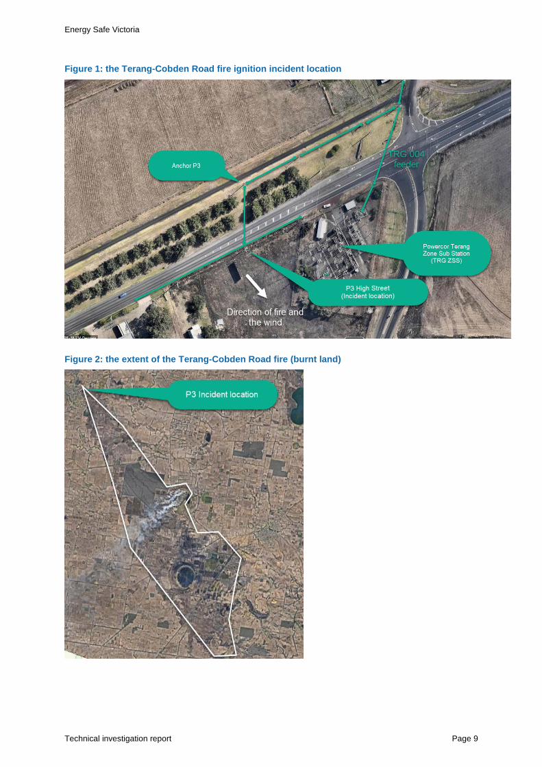
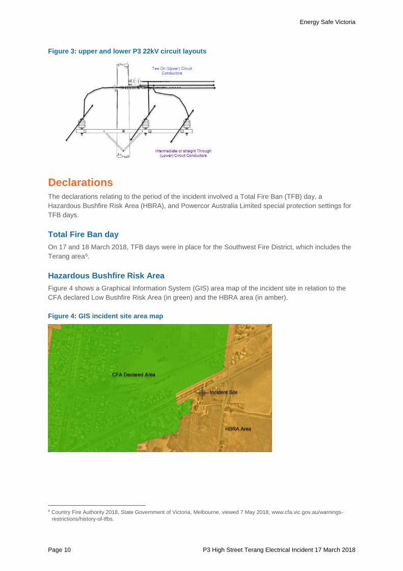
Figure 1 and Figure 2 show aerial views of the incident location of the Terang-Cobden Road fire and the extent of the damage (respectively). Figure 3 shows a diagram of P3 and the arrangement of its upper and lower circuits, which are both 22kV. P3 also carries the Terang to Warrnambool No.2 66kV line in parallel from a crossarm at the top of P3, however there is ample clearance between the lower 22kV and the higher 66kV conductors and there was no evidence to indicate the 66kV line in any way contributed to, or was involved in the incident. This is not shown on the diagram and does not otherwise factor in the investigation.
4 This line runs in parallel above TRG 004. 5 P3 (LIS # 409916) has a lower 22kV circuit that attaches to an upper 22kV circuit that crosses the Princess Highway to the
high voltage anchor pole (LIS # 408500).
Energy Safe Victoria
Technical investigation report Page 9
Figure 1: the Terang-Cobden Road fire ignition incident location
Figure 2: the extent of the Terang-Cobden Road fire (burnt land)
Energy Safe Victoria
Page 10 P3 High Street Terang Electrical Incident 17 March 2018
Figure 3: upper and lower P3 22kV circuit layouts
Declarations The declarations relating to the period of the incident involved a Total Fire Ban (TFB) day, a Hazardous Bushfire Risk Area (HBRA), and Powercor Australia Limited special protection settings for TFB days.
Total Fire Ban day On 17 and 18 March 2018, TFB days were in place for the Southwest Fire District, which includes the Terang area6.
Hazardous Bushfire Risk Area Figure 4 shows a Graphical Information System (GIS) area map of the incident site in relation to the CFA declared Low Bushfire Risk Area (in green) and the HBRA area (in amber).
Figure 4: GIS incident site area map
6 Country Fire Authority 2018, State Government of Victoria, Melbourne, viewed 7 May 2018, www.cfa.vic.gov.au/warnings-
restrictions/history-of-tfbs.
Energy Safe Victoria
Technical investigation report Page 11
Powercor Australia Limited special protection settings Powercor Australia Limited has an accepted (by ESV) bushfire management plan (including any actions required) for managing risk on TFB days. The plan, which considers a number of factors including environmental, involves initiating special protection (suppression) settings for identified assets:
• The TRG 004 feeder circuit breaker is an identified asset to which TFB day settings should be applied7
• The TRG 004 feeder circuit breaker protection settings were logged as suppressed on 17 March 2018 at 11:10 AEST and restored on 18 March 2018 at 00:33 AEST8. This terminology means that the protection was set to operate more quickly (i.e. the fast overcurrent setting)
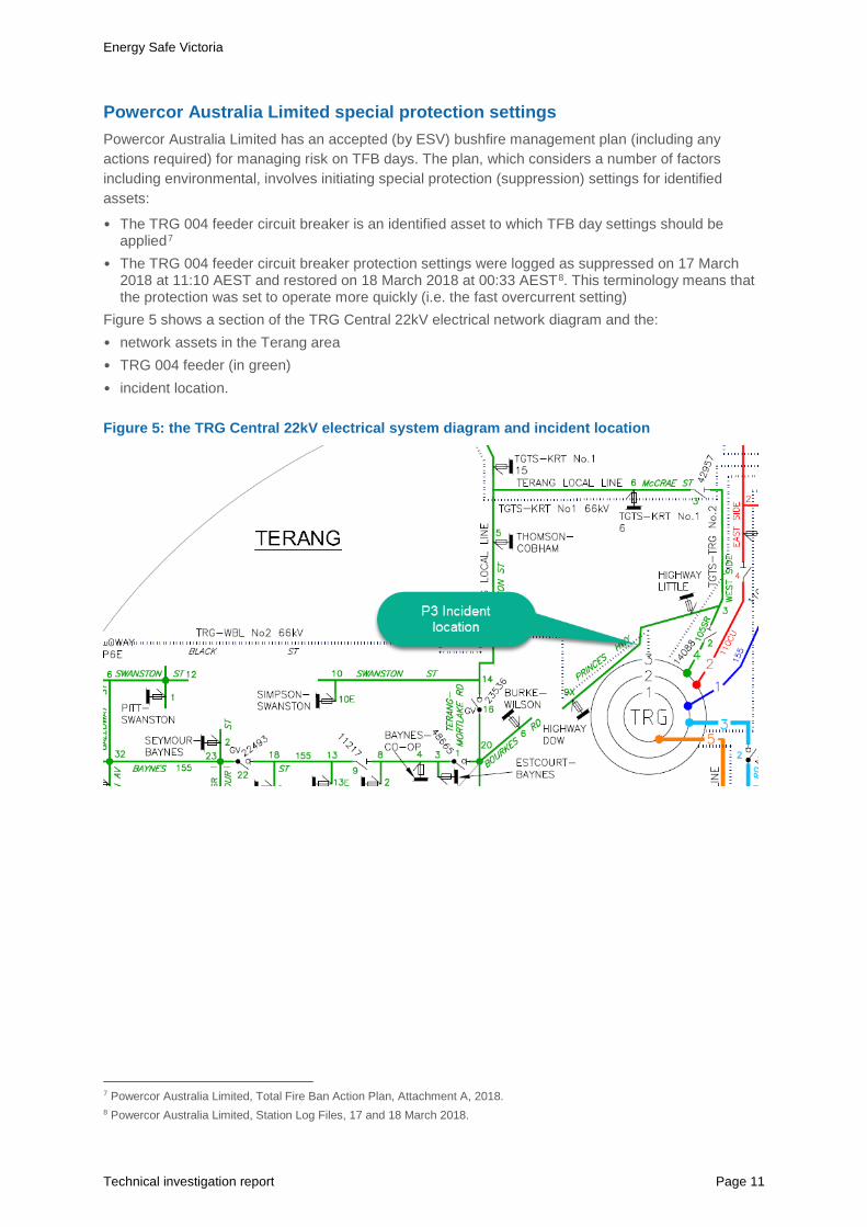
Figure 5 shows a section of the TRG Central 22kV electrical network diagram and the: • network assets in the Terang area • TRG 004 feeder (in green) • incident location.
Figure 5: the TRG Central 22kV electrical system diagram and incident location
7 Powercor Australia Limited, Total Fire Ban Action Plan, Attachment A, 2018. 8 Powercor Australia Limited, Station Log Files, 17 and 18 March 2018.
Energy Safe Victoria
Page 12 P3 High Street Terang Electrical Incident 17 March 2018
Investigation sequence of events On 18 March 2018:
• Victoria Police requested ESV’s attendance at the incident site to help identify the cause of ignition near the TRG ZSS
• ESV dispatched an enforcement officer at 15:20 AEST to the incident site to meet with the Powercor Australia Limited Network Availability Officer and representatives from Victoria Police
• the Powercor Australia Limited Network Availability Officer showed a video of the span of conductors involved in the incident. The video was taken on 18 March 2018 at approximately 11:40 AEST
• the ESV enforcement officer took pictures of the P3 electrical conductors showing arcing damage
– measured the height of the conductor span9 that crosses the Princess Highway.
On 19 March 2018, ESV’s Head of Regulatory Assurance produced the South West Fires Summary Update for ESV Senior Management10.
On 28 March 2018, ESV’s formal technical investigation was approved by the General Manager, Electrical Safety and Technical Regulation.
On 3 April 2018, ESV required Powercor Australia Limited to supply relevant documents and information under Section 134 of the Electrical Safety Act 1998.
On 10 April 2018, Powercor Australia Limited responded by providing the relevant documents and other information requested by ESV.
On 13 April 2018, ESV attended the incident site to collect more information relating to the electrical assets.
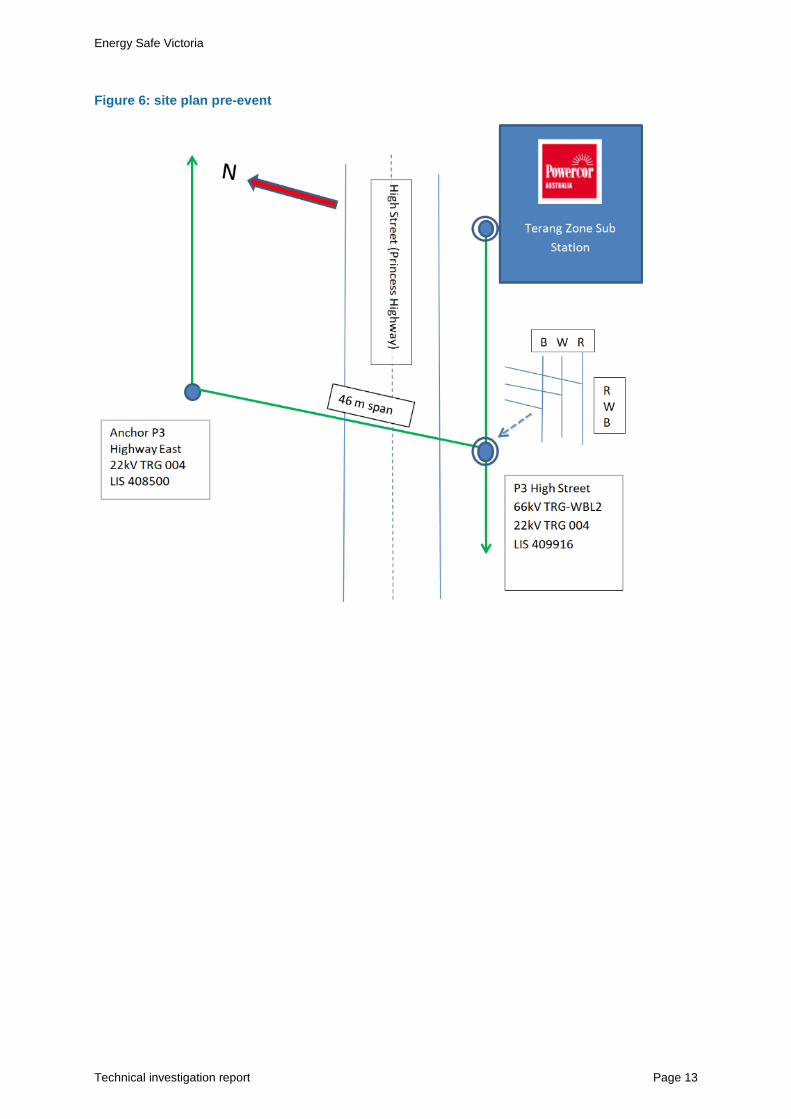
Site plan Figure 6 shows a plan of the incident location prior to the incident that includes the:
• Terang Zone Substation (TRG ZSS) • P3 and Anchor P3 (and their corresponding unique line information system (LIS) numbers) in
relation to High Street (Princess Highway) • the distance of the span crossing High Street • way the three conductors were bridged (joined) at P3 (indicated by the symbols R W B; see
Figure 10 for more information about the Red, White and Blue Phases).
9 The Suparule Cable Height Meter measures cable sag, cable height, and overhead clearance. For more information see
http://www.suparule.com/products/cable-height-meter/. 10 Fox, B, Head of Regulatory Assurance, South West Fires Summary Update, March 2018, Energy Safe Victoria, State
Government of Victoria, Melbourne.
Energy Safe Victoria
Technical investigation report Page 13
Figure 6: site plan pre-event
Energy Safe Victoria
Page 14 P3 High Street Terang Electrical Incident 17 March 2018
Technical investigation ESV’s technical investigation has involved:
• mapping the incident site after the event • inspecting asset evidence, including video evidence, photographic evidence, and the
damaged conductor sections • collecting and reviewing relevant asset information, including P3’s construction history, the
relevant standards applying to network asset maintenance, and P3’s records of repair • reviewing the records of inspection for the network assets involved • reviewing the TRG 004 feeder protection equipment operation records • studying prevailing weather information from the Bureau of Meteorology and Emergency
Management Victoria.
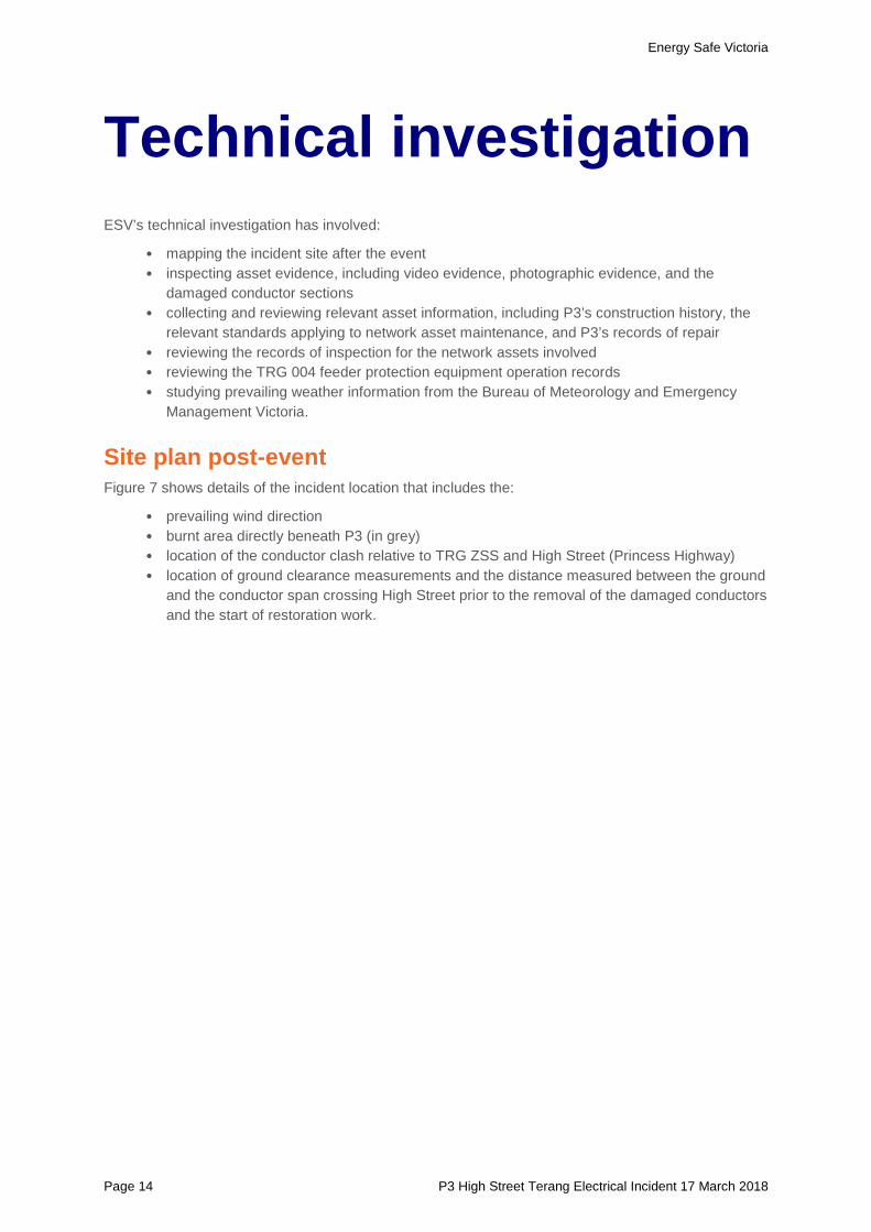
Site plan post-event Figure 7 shows details of the incident location that includes the:
• prevailing wind direction • burnt area directly beneath P3 (in grey) • location of the conductor clash relative to TRG ZSS and High Street (Princess Highway) • location of ground clearance measurements and the distance measured between the ground
and the conductor span crossing High Street prior to the removal of the damaged conductors and the start of restoration work.
Energy Safe Victoria
Technical investigation report Page 15
Figure 7: site plan post-event
Asset evidence
Video analysis On 18 March 2018, following identification of the fault location, Powercor Australia Limited recorded a video of the site at approximately 11:40 AEST11. The video shows the:
• possible range of movement of the conductors due to gusting winds (up to 96 kilometres per hour recorded at the Warrnambool Weather Station at 11:15 AEST, and 76 kilometres per hour recorded at the Mortlake Weather Station at 11:28 AEST)
• changes in clearance between the upper and lower conductors.
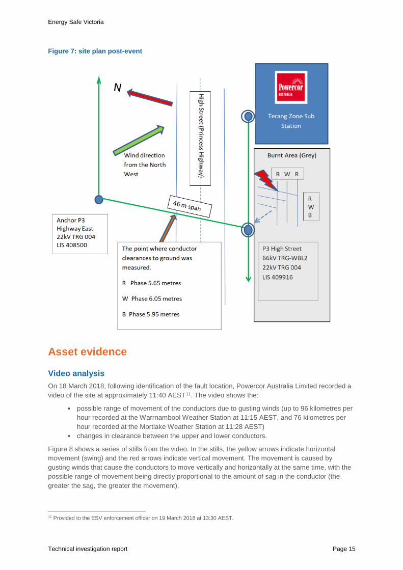
Figure 8 shows a series of stills from the video. In the stills, the yellow arrows indicate horizontal movement (swing) and the red arrows indicate vertical movement. The movement is caused by gusting winds that cause the conductors to move vertically and horizontally at the same time, with the possible range of movement being directly proportional to the amount of sag in the conductor (the greater the sag, the greater the movement).
11 Provided to the ESV enforcement officer on 19 March 2018 at 13:30 AEST.
Energy Safe Victoria
Page 16 P3 High Street Terang Electrical Incident 17 March 2018
Figure 8: video stills showing the range of conductor movement (horizontal and vertical)
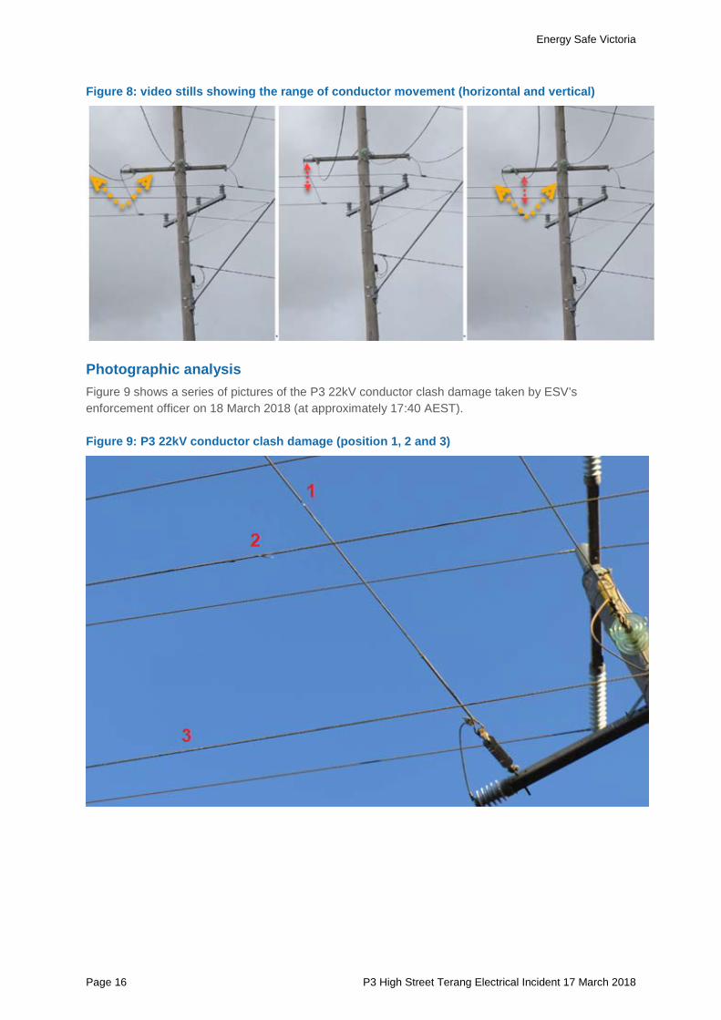
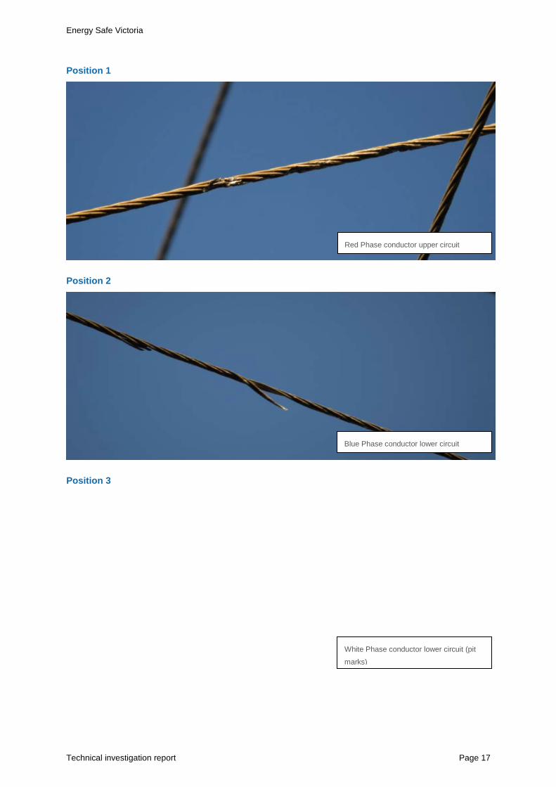
Photographic analysis Figure 9 shows a series of pictures of the P3 22kV conductor clash damage taken by ESV’s enforcement officer on 18 March 2018 (at approximately 17:40 AEST).
Figure 9: P3 22kV conductor clash damage (position 1, 2 and 3)
Energy Safe Victoria
Technical investigation report Page 17
Position 1
Position 2
Position 3
Red Phase conductor upper circuit
Blue Phase conductor lower circuit
White Phase conductor lower circuit (pit marks)
Energy Safe Victoria
Page 18 P3 High Street Terang Electrical Incident 17 March 2018
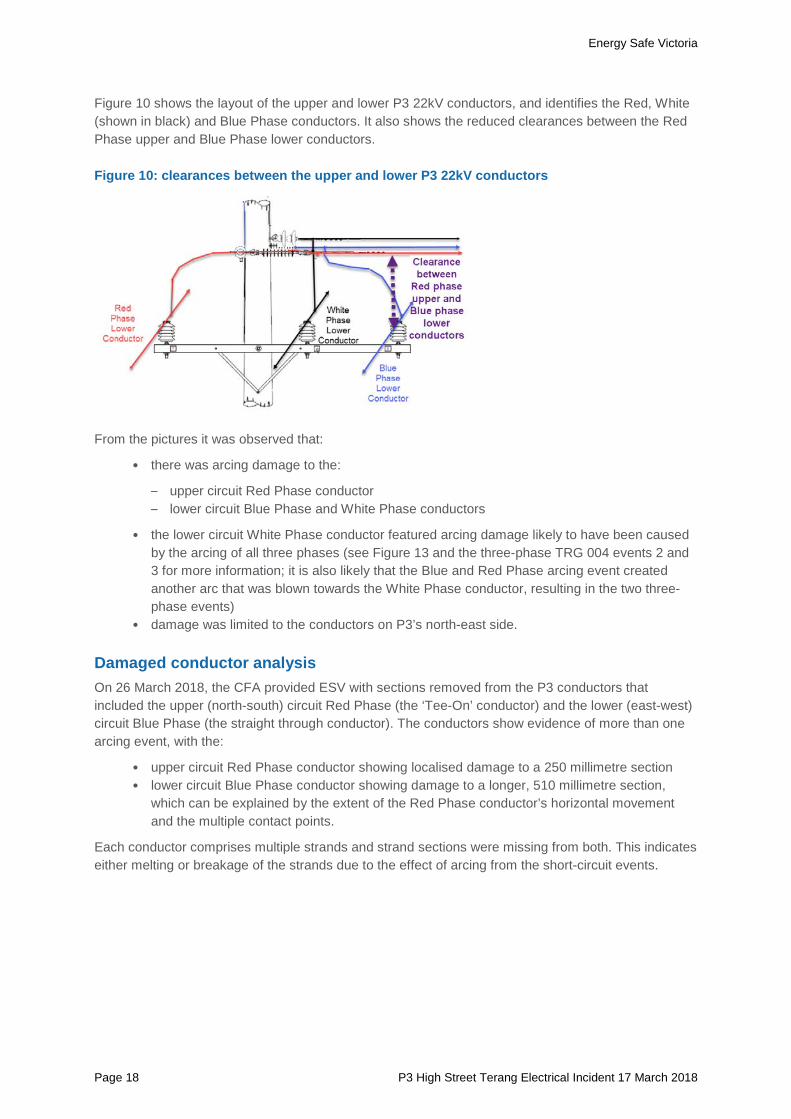
Figure 10 shows the layout of the upper and lower P3 22kV conductors, and identifies the Red, White (shown in black) and Blue Phase conductors. It also shows the reduced clearances between the Red Phase upper and Blue Phase lower conductors.
Figure 10: clearances between the upper and lower P3 22kV conductors
From the pictures it was observed that:
• there was arcing damage to the:
– upper circuit Red Phase conductor – lower circuit Blue Phase and White Phase conductors
• the lower circuit White Phase conductor featured arcing damage likely to have been caused by the arcing of all three phases (see Figure 13 and the three-phase TRG 004 events 2 and 3 for more information; it is also likely that the Blue and Red Phase arcing event created another arc that was blown towards the White Phase conductor, resulting in the two three-phase events)
• damage was limited to the conductors on P3’s north-east side.
Damaged conductor analysis On 26 March 2018, the CFA provided ESV with sections removed from the P3 conductors that included the upper (north-south) circuit Red Phase (the ‘Tee-On’ conductor) and the lower (east-west) circuit Blue Phase (the straight through conductor). The conductors show evidence of more than one arcing event, with the:
• upper circuit Red Phase conductor showing localised damage to a 250 millimetre section • lower circuit Blue Phase conductor showing damage to a longer, 510 millimetre section,
which can be explained by the extent of the Red Phase conductor’s horizontal movement and the multiple contact points.
Each conductor comprises multiple strands and strand sections were missing from both. This indicates either melting or breakage of the strands due to the effect of arcing from the short-circuit events.
Energy Safe Victoria
Technical investigation report Page 19
Asset information
P3 construction history Powercor Australia Limited provided ESV with detailed route plans (DRP) of the area around P3 dating back to 1976. The DRPs:
• record the designs and act as the area’s as-built record • explain the structure types and refer to relevant construction standards • are updated when new construction work requires an asset design change.
DRPs do not record like-for-like replacement under maintenance.
The most recent plan indicates design and construction changes up to March 2008, while historical details include the following:
• the original construction design required aluminium conductor steel reinforced (ACSR) ‘Tee-On’ conductors to be tensioned to an all-aluminium conductor stringing chart.
• one of the P3 22kV circuits is not as described by the DRP (being a 6/1/.144 ACSR type and not the 6/.186 ACSR type as described).
• P3 was constructed to an old State Electricity Commission of Victoria (SECV) drawing and originally featured wooden crossarms. Both crossarms have since been changed, with the lower crossarm replaced in December 2009.
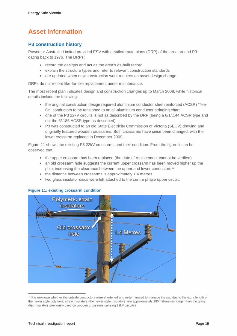
Figure 11 shows the existing P3 22kV crossarms and their condition. From the figure it can be observed that:
• the upper crossarm has been replaced (the date of replacement cannot be verified) • an old crossarm hole suggests the current upper crossarm has been moved higher up the
pole, increasing the clearance between the upper and lower conductors12 • the distance between crossarms is approximately 1.4 metres • two glass insulator discs were left attached to the centre phase upper circuit.
Figure 11: existing crossarm condition
12 It is unknown whether the outside conductors were shortened and re-terminated to manage the sag due to the extra length of the newer style polymeric strain insulators.(the newer style insulators are approximately 280 millimetres longer than the glass disc insulators previously used on wooden crossarms carrying 22kV circuits)
Energy Safe Victoria
Page 20 P3 High Street Terang Electrical Incident 17 March 2018
Relevant standards The current standards relevant to these network assets and the circumstances of the event involve:
• phase-to-phase clearances specified by the
– Overhead Line Design Standard AS/NZS 7000:2016 – Powercor Australia Limited Distribution Construction Standard (DC161)
• conductor-to-road/ground clearances specified by the
– Overhead Line Design Standard AS/NZS 7000:2016 – Powercor Australia Limited Technical Standard (DC111).
The above Powercor standards were applicable in December 2009 when P3 was last maintained. AS/NZS 7000 was first released in 2010, its predecessor (which AS/NZS 7000 was based on) was industry guideline Energy Networks Australia (ENA) C(b)1 2006. The relevant requirements of both are the same. Legacy SECV standards applicable to the initial construction in the 1970’s were not considered relevant to the investigation.
Repairs On 19 March 2018, Powercor Australia Limited crews completed repairs that included:
• replacing the damaged conductor sections • straightening Anchor P3.
ESV requested that measurements be taken of the conductor phase-to-phase clearances between the upper and lower P3 conductors before and after the repairs.
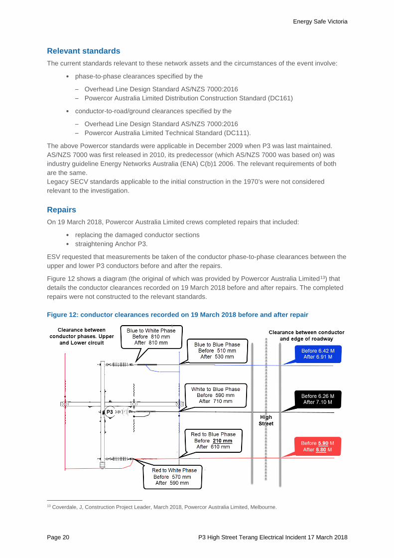
Figure 12 shows a diagram (the original of which was provided by Powercor Australia Limited13) that details the conductor clearances recorded on 19 March 2018 before and after repairs. The completed repairs were not constructed to the relevant standards.
Figure 12: conductor clearances recorded on 19 March 2018 before and after repair
13 Coverdale, J, Construction Project Leader, March 2018, Powercor Australia Limited, Melbourne.

Energy Safe Victoria
Technical investigation report Page 21
Phase-to-phase clearance standards The phase-to-phase clearances measured by Powercor Australia Limited between the upper and lower 22kV conductors (ranging from 210 millimetres14 to 810 millimetres before repair) were all less than the 900 millimetre phase-to-phase clearance specified by the:
• Overhead Line Design Standard AS/NZS 7000:2016 • Powercor Australia Limited Distribution Construction Standard (DC161).
Conductor-to-road/ground clearance standards • The conductor-to-road/ground clearances measured by Powercor Australia Limited ranged
from 5,900 millimetres to 6,420 millimetres before repair. The Overhead Line Design Standard AS/NZS 7000:2016 and the Powercor Australia Limited Technical Standard (DC111) specify a minimum clearance of 6900 millimetres.
Following repairs, the conductor-to-road clearance of one conductor did not meet this standard.
Network asset inspections Powercor Australia Limited has contracted out its network asset inspection services to Electrix Pty Ltd for more than ten years. Under this agreement, Electrix Pty Ltd inspectors record site inspection information, which is transferred to Powercor Australia Limited’s maintenance section.
Over the last ten years, Electrix Pty Ltd inspected15:
• P3 four times (on 17 January 2007, 21 December 2011, 7 July 2014, and 3 January 2017) • Anchor P3 three times (on 17 February 2012, 3 September 2014, and 9 February 2017).
The records provided show no evidence of reduced clearances being logged as a defect, and it is unknown exactly when (or how) the reduced conductor clearances occurred.
Documents that are relevant to the network asset inspection process include the Powercor Australia Limited Asset Management Plan and Asset Inspection Manual.
Asset Management Plan The Asset Management Plan for overhead conductors provides the following information16:
Section 3.3, Asset Condition and Age Profile, states:
“Where multiple circuits are supported by the same poles there is further need to ensure that conductors are in serviceable condition and lines appropriately designed to mitigate the likelihood of circuit to circuit contact.”
Section 3.6, Condition Monitoring, states:
“Overhead conductors are inspected during the normal inspection processes as mentioned below.
- Pole inspection - visual survey with focus on the conductor condition at the pole top.
Conductors that exhibit visible signs of mechanical degradation like corrosion, out of sag, caging broken strands, vibration damage and other defects are identified during the above inspection processes”
14 The clearance between the Red Phase to Blue Phase conductors that clashed and arced. 15 Powercor Australia Limited information system. 16 Powercor Australia Limited, Asset Management Plan, Document No. 01-00-M0015 (PAL-AMP-07), Issue 3.0, 23 February
2015, p. 12, 14, 27.
Energy Safe Victoria
Page 22 P3 High Street Terang Electrical Incident 17 March 2018
Section 6.4.3, Interpretation, states:
“…continue the current practice of asset inspectors checking for non-compliant ground clearance and “out of sag” conductors in single circuit bare open wire power lines in the cyclic inspection program. These instances are reported and actioned in accordance with the Network Asset Maintenance Priority Policy (Document No 05-C001.A – 025).”
The asset inspection records show no evidence that visible signs of degradation, non-compliant ground clearance or incorrectly sagged conductors were identified when P3 and Anchor P3 were inspected.
The Powercor asset management plan17 states that it “will assess all spans of multi circuit high voltage bare open wire conductor for compliance with the requirements of ENA C(b)1 Section 10.3 “Guidelines for Design and Maintenance of Overhead Transmission and Distribution lines; this assessment will require a greater standard of data acquisition and analysis than is available in the cyclic asset inspection programme and so will be subject to a separate programme of special survey to establish and record the spatial relationship of conductors and conduct engineering design checks that will be designed to be completed in time to enable any required re-construction works or fitting of spacers (spreaders) to be completed by the time frames stated in part f of the direction i.e. 1 Nov 2016 for HBRA and 1 Nov 2020 for LBRA.”
Asset Inspection Manual The Asset Inspection Manual work instruction18:
• states that aerial line ground clearances are to be inspected as part of cyclic and non-cyclic inspection programs
• details the required definitions for (and expectations from) assessment tasks and how they are to be reported.
No records have been found of ground clearance measurements being taken at the incident site or of any defects being raised.
Operations records The protection settings on theTRG004 circuit breaker located at TRG ZSS were set to cause the circuit breaker to operate in a shorter than normal time (i.e. fast overcurrent) at the time of the incident.
Figure 13 shows an excerpt from Powercor Australia Limited’s TRG 004 feeder protection equipment operation information. The excerpt indicates that on 17 March 2018 there were four short circuit events between 20:45 and 20:49 AEST:
• two events (No. 4 and 5) included the Red and Blue Phase conductors (phase-to-phase). • two events (No. 2 and 3) included the Red, White and Blue Phase conductors (three phase).
These events collectively identify all three conductor phases as being involved in the events, which is consistent with the visual damage observed to the three conductors at P3.
17 Powercor Australia Ltd Asset Management Plan (PAL-AMP-07), section 6.4.3. 23/02/2015. Iss.3.0. 18 Powercor Australia Limited, Asset Inspection Manual, Work Instruction for Inspection of Aerial Line Ground Clearances,
Section G.4-WI.

Energy Safe Victoria
Technical investigation report Page 23
Figure 13: Terang 004 feeder protection equipment operation information
Had the protection been set not to reclose (as would have been the case on a Code Red Day) the circuit breaker would only have operated once (event No. 5) and then locked open until the line had been inspected.
Prevailing weather information
Bureau of Meteorology Information Warrnambool and Mortlake are the closest weather stations to the incident site. Prevailing weather information on the day has been sourced from the Bureau of Meteorology (BOM) website19.
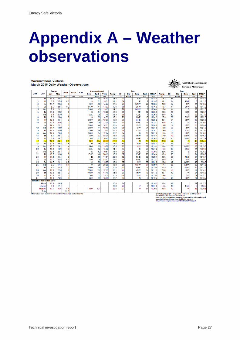
Figure 14 shows an excerpt from the Warrnambool Weather Station records, which indicates that on 17 March 2018 at 20:00 AEST, north westerly winds with a maximum gust of 104 kilometres per hour were recorded.
Figure 14: excerpt from the Warrnambool weather record for March 2018
See Appendix A for more information.
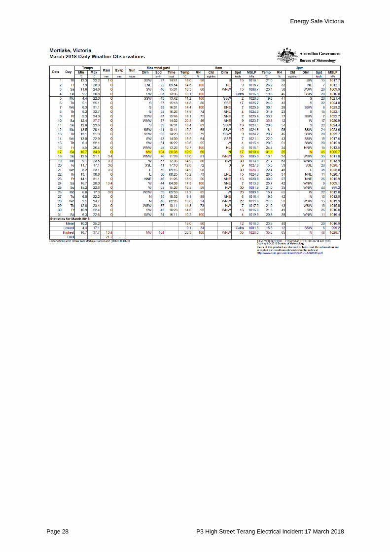
Figure 15 shows an excerpt from the Mortlake Weather Station records, which indicates that on the 17 March 2018 at 20:08 AEST, north westerly winds with a maximum gust of 104 kilometres per hour were recorded.
Figure 15: excerpt from the Mortlake weather record for March 2018
See Appendix A for more information.
19 Bureau of Meteorology 2018, Australian Government, viewed 14 April 2018, www.bom.gov.au.
Energy Safe Victoria
Page 24 P3 High Street Terang Electrical Incident 17 March 2018
Emergency Management Victoria information Emergency Management Victoria provided ESV with a more detailed weather record from the Mortlake Automatic Weather Station to establish whether the 17 March 2018 high wind event was unusual20. The record covered the period from 09:00 AEST on 17 March 2018 to 08:30 AEST on 18 March 2018, and while it provided more information about the intensity of the wind and when wind conditions changed, it offered no evidence that the wind event was exceptional.
20 State Control Centre (Intelligence Section), mortlake aws_terang fire.xlsx, viewed May 2018.
Energy Safe Victoria
Technical investigation report Page 25
Findings and conclusions ESV’s findings and conclusions specifically relate to the source of the Terang-Cobden Road fire and the role played by the conductor clearances, the relevant conductor clearance standards, and the network asset inspection process.
The source of the Terang-Cobden Road fire The most likely source of the Terang-Cobden Road fire on 17 March 2018 was molten material falling from clashing and arcing conductors near P3 at or around 20:49 AEST due to a high wind event, as evidenced by arcing damage to the three 22kV conductors.
Circuit breaker operations The protection settings on theTRG004 circuit breaker located at TRG ZSS were set to cause the circuit breaker to operate in a shorter than normal (i.e. fast overcurrent) time at the time of the incident.
The circuit breaker operated four times with settings applied in accordance with the current approved Powercor Bushfire Mitigation Plan.
Had the protection been set not to reclose (as would have been the case on a Code Red Day) it would only have operated one.
Conductor clearances On 17 March 2018, the clearances between the upper and lower P3 22kV conductors were insufficient to prevent clashing and arcing during the high wind event.
Construction to standards The lines were not constructed to maintain the P3 22kV conductor clearances (both phase-to-phase and conductor-to-road/ground) as specified in the standard
Phase-to-phase clearance requirements are stated in the:
• Australian Overhead Line Design Standard AS/NZS 7000:2016 • Powercor Australia Limited Distribution Construction Standard DC161.
Both standards specify a 900 millimetre clearance. The clearances between the upper and lower 22kV conductors ranged from 210 millimetres to 810 millimetres.
Conductor-to-road/ground clearance requirements are stated in the:
• Australian Overhead Line Design Standard AS/NZS 7000:2016 • Powercor Australia Limited Technical Standard DC111.
Both standards specify a 6,900 millimetre clearance between the conductors and the road. The clearances ranged from 5,900 millimetres to 6,420 millimetres.
Energy Safe Victoria
Page 26 P3 High Street Terang Electrical Incident 17 March 2018
The network asset inspection process Over the last 10 years:
• P3 was inspected four times (on 17 January 2007, 21 December 2011, 7 July 2014, and 3 January 2017)
• Anchor P3 was inspected three times (on 17 February 2012, 3 September 2014, and 9 February 2017).
There is no evidence from the inspection records that conductor clearances have been logged as a defect or that ground clearance measurements were taken.
Energy Safe Victoria
Technical investigation report Page 27
Appendix A – Weather observations
Energy Safe Victoria
Page 28 P3 High Street Terang Electrical Incident 17 March 2018


![Incident Management Procedure - AECOM Safeguard€¦ · Incident Management Procedure (S3[APAC]-004-PR1) Revision 0 May 8, 2018 PRINTED COPIES ARE UNCONTROLLED. CONTROLLED COPY IS](https://img.pdfslide.us/doc/110x75/5fc0b2ee85a6a35a1440a6f4/incident-management-procedure-aecom-safeguard-incident-management-procedure-s3apac-004-pr1.jpg)