Embed Size (px)
Citation preview
Series OCG Pneumatic Cylinders
The Price Alternative
New Metric Models
• ImperialandMetric• Rebuildableroundbodycylinders• 6boresizes• 10standardstrokelengths• Highspeed/doubleacting
OCG02
www.phdinc.com(800)624-8511
2(800) 624-8511www.phdinc.com/ocg OCG02
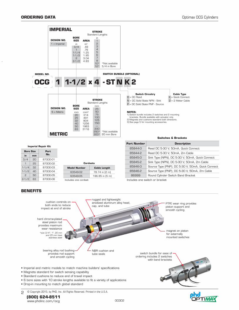
MODEL NO. SWITCH BUNDLE (OPTIONAL)
D = DC ReedN = DC Solid State NPN - SinkP = DC Solid State PNP - Source
K = Quick Connect2 = 2 Meter Cable
Switch Circuitry Cable Type
BORESIZE AREA
1 = Imperial
DESIGN NO.
IMPERIAL
OCG 1-1/21 x - 4 ST 2N K
NOTES:1) Switch bundle includes 2 switches and 2 mounting
brackets. Bundle available with actuator only.2) Magnets and cushions standard both directions.3) See page 5 for mounting accessories.
in3/4
11-1/41-1/2
22-1/2
in2
.49
.761.251.953.044.83
in12345678
10*12*
STROKEStandard Lengths
*Not available3/4 in Bore
BORESIZE AREA
5 = Metric
DESIGN NO.
METRIC
mm202532405063
mm2
314491804
125619633116
mm255075
100125150—
200250*300*
STROKEStandard Lengths
*Not available20 mm Bore
• Imperial and metric models to match machine builders' specifications• Magnets standard for switch sensing capability• Standard cushions to reduce end of travel impact• 6 bore sizes with 10 stroke lengths available to fit a variety of applications• Drop-in mounting to match global standard
cushion controls on both ends to reduce
impact at end of stroke
hard chrome-platedsteel piston rod
provides maximumwear resistance
*size 3/4", 1", 20 mm and 25 mm have
stainless steel
NBR cushion and tube seals
magnet on piston for externally mounted switches
rugged and lightweight anodized aluminum alloy head, cap, and tube
PTFE wear ring provides piston support and smooth cycling
bearing alloy rod bushing provides rod support
and smooth cyclingswitch bundle for ease of
ordering includes 2 switches with band brackets
ORDERING DATA Optimax OCG Cylinders
BENEFITS
© Copyright 2015, by PHD, Inc. All Rights Reserved. Printed in the U.S.A.
Switches & Brackets
Part Number Description
85844-0 Reed DC 5-30 V, 50mA, Quick Connect
85844-2 Reed DC 5-30 V, 50mA, 2m Cable
85845-0 Sink Type (NPN), DC 5-30 V, 50mA, Quick Connect
85845-2 Sink Type (NPN), DC 5-30 V, 50mA, 2m Cable
85846-0 Source Type (PNP), DC 5-30 V, 50mA, Quick Connect
85846-2 Source Type (PNP), DC 5-30 V, 50mA, 2m Cable
86999 Round Cylinder Switch Band Bracket
Includes one switch or bracket
Cordsets
Model Number Cable Length
63549-02 78.74 in [2 m]
63549-05 196.85 in [5 m]
Includes one cordset
Imperial Repair Kit
Bore Size Part No.in mm
3/4 20 87000-01
1 25 87000-02
1-1/4 32 87000-03
1-1/2 40 87000-04
2 50 87000-05
2-1/2 63 87000-06
3(800) 624-8511www.phdinc.com/ocgOCG02
ENGINEERING DATA Optimax OCG Cylinders
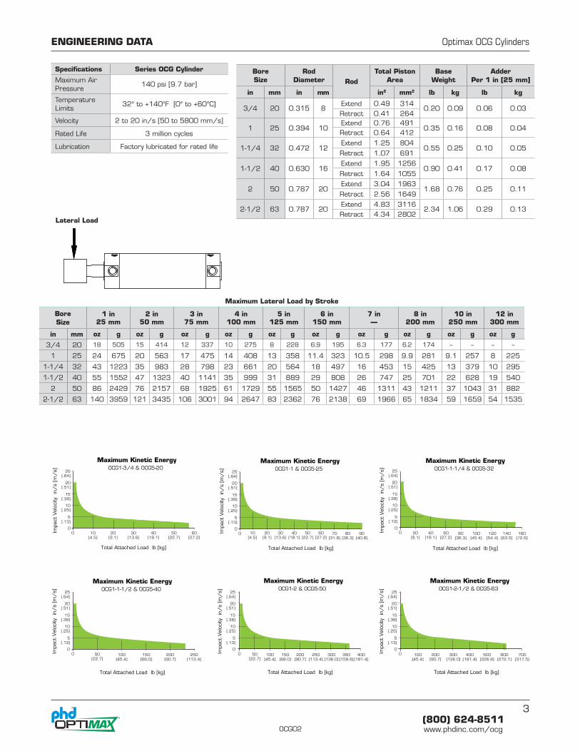
Specifications Series OCG Cylinder
Maximum Air Pressure
140 psi [9.7 bar]
Temperature Limits
32° to +140°F [0° to +60°C]
Velocity 2 to 20 in/s [50 to 5800 mm/s]
Rated Life 3 million cycles
Lubrication Factory lubricated for rated life
Bore Size
Rod Diameter Rod
Total Piston Area
Base Weight
AdderPer 1 in [25 mm]
in mm in mm in2 mm2 lb kg lb kg
3/4 20 0.315 8Extend 0.49 314
0.20 0.09 0.06 0.03Retract 0.41 264
1 25 0.394 10Extend 0.76 491
0.35 0.16 0.08 0.04Retract 0.64 412
1-1/4 32 0.472 12Extend 1.25 804
0.55 0.25 0.10 0.05Retract 1.07 691
1-1/2 40 0.630 16Extend 1.95 1256
0.90 0.41 0.17 0.08Retract 1.64 1055
2 50 0.787 20Extend 3.04 1963
1.68 0.76 0.25 0.11Retract 2.56 1649
2-1/2 63 0.787 20Extend 4.83 3116
2.34 1.06 0.29 0.13Retract 4.34 2802
Maximum Lateral Load by Stroke
Bore Size
1 in25 mm
2 in50 mm
3 in75 mm
4 in100 mm
5 in125 mm
6 in150 mm
7 in—
8 in200 mm
10 in250 mm
12 in300 mm
in mm oz g oz g oz g oz g oz g oz g oz g oz g oz g oz g
3/4 20 18 505 15 414 12 337 10 275 8 228 6.9 195 6.3 177 6.2 174 -- -- -- --
1 25 24 675 20 563 17 475 14 408 13 358 11.4 323 10.5 298 9.9 281 9.1 257 8 225
1-1/4 32 43 1223 35 983 28 798 23 661 20 564 18 497 16 453 15 425 13 379 10 295
1-1/2 40 55 1552 47 1323 40 1141 35 999 31 889 29 808 26 747 25 701 22 628 19 540
2 50 86 2429 76 2157 68 1925 61 1729 55 1565 50 1427 46 1311 43 1211 37 1043 31 882
2-1/2 63 140 3959 121 3435 106 3001 94 2647 83 2362 76 2138 69 1966 65 1834 59 1659 54 1535
Maximum Kinetic EnergyOCG1-2 & OCG5-50
Maximum Kinetic EnergyOCG1-1-1/4 & OCG5-32
Maximum Kinetic EnergyOCG1-1-1/2 & OCG5-40
Maximum Kinetic EnergyOCG1-1 & OCG5-25
Total Attached Load lb [kg]
Total Attached Load lb [kg] Total Attached Load lb [kg]
Total Attached Load lb [kg]
0
Maximum Kinetic EnergyOCG1-2-1/2 & OCG5-63
Total Attached Load lb [kg]
0
0 70[31.8]
80[36.3]
90[40.8]
0
0
Maximum Kinetic EnergyOCG1-3/4 & OCG5-20
Total Attached Load lb [kg]
Impa
ct V
eloc
ity
in/
s [m
/s] 25
[.64]
20[.51]
15[.38]
10[.25]
5[.13]
0
Impa
ct V
eloc
ity
in/
s [m
/s] 25
[.64]
20[.51]
15[.38]
10[.25]
5[.13]
0
Impa
ct V
eloc
ity
in/
s [m
/s] 25
[.64]
20[.51]
15[.38]
10[.25]
5[.13]
0
Impa
ct V
eloc
ity
in/
s [m
/s] 25
[.64]
20[.51]
15[.38]
10[.25]
5[.13]
0
Impa
ct V
eloc
ity
in/
s [m
/s] 25
[.64]
20[.51]
15[.38]
10[.25]
5[.13]
0 Impa
ct V
eloc
ity
in/
s [m
/s] 25
[.64]
20[.51]
15[.38]
10[.25]
5[.13]
00 10
[4.5]10
[4.5]20
[9.1]20
[9.1]30
[13.6]30
[13.6]40
[18.1]40
[18.1]50
[22.7]50
[22.7]60
[27.2]60
[27.2]80
[36.3]100
[45.4]
50[22.7]
50[22.7]
100[45.4]
100[45.4]
100[45.4]
150[68.0]
150[68.0]
200[90.7]
200[90.7]
200[90.7]
250[113.4]
250[113.4]
300[136.0]
300[136.0]
350[158.8]
400[181.4]
400[181.4]
500[226.8]
600[272.1]
700[317.5]
120[54.4]
140[63.5]
160[72.6]
20[9.1]
40[18.1]
60[27.2]
Lateral Load
4(800) 624-8511www.phdinc.com/ocg OCG02
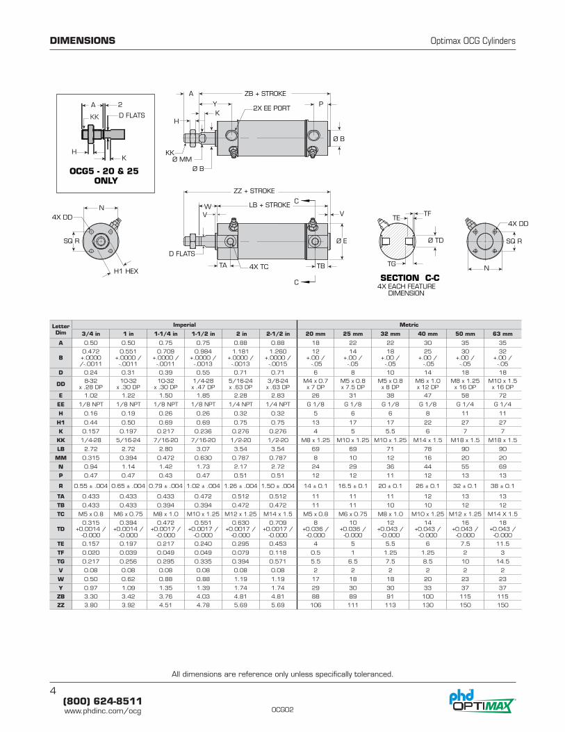
LetterDim
Imperial Metric
3/4 in 1 in 1-1/4 in 1-1/2 in 2 in 2-1/2 in 20 mm 25 mm 32 mm 40 mm 50 mm 63 mm
A 0.50 0.50 0.75 0.75 0.88 0.88 18 22 22 30 35 35
B0.472 +.0000 /-.0011
0.551 +.0000 /
-.0011
0.709 +.0000 /
-.0011
0.984 +.0000 /
-.0013
1.181 +.0000 /
-.0013
1.260 +.0000 /
-.0015
12 +.00 / -.05
14 +.00 /
-.05
18 +.00 /
-.05
25 +.00 / -.05
30 +.00 /
-.05
32 +.00 /
-.05
D 0.24 0.31 0.39 0.55 0.71 0.71 6 8 10 14 18 18
DD 8-32 x .28 DP
10-32 x .30 DP
10-32 x .30 DP
1/4-28 x .47 DP
5/16-24 x .63 DP
3/8-24 x .63 DP
M4 x 0.7 x 7 DP
M5 x 0.8 x 7.5 DP
M5 x 0.8 x 8 DP
M6 x 1.0 x 12 DP
M8 x 1.25 x 16 DP
M10 x 1.5 x 16 DP
E 1.02 1.22 1.50 1.85 2.28 2.83 26 31 38 47 58 72
EE 1/8 NPT 1/8 NPT 1/8 NPT 1/8 NPT 1/4 NPT 1/4 NPT G 1/8 G 1/8 G 1/8 G 1/8 G 1/4 G 1/4
H 0.16 0.19 0.26 0.26 0.32 0.32 5 6 6 8 11 11
H1 0.44 0.50 0.69 0.69 0.75 0.75 13 17 17 22 27 27
K 0.157 0.197 0.217 0.236 0.276 0.276 4 5 5.5 6 7 7
KK 1/4-28 5/16-24 7/16-20 7/16-20 1/2-20 1/2-20 M8 x 1.25 M10 x 1.25 M10 x 1.25 M14 x 1.5 M18 x 1.5 M18 x 1.5
LB 2.72 2.72 2.80 3.07 3.54 3.54 69 69 71 78 90 90
MM 0.315 0.394 0.472 0.630 0.787 0.787 8 10 12 16 20 20
N 0.94 1.14 1.42 1.73 2.17 2.72 24 29 36 44 55 69
P 0.47 0.47 0.43 0.47 0.51 0.51 12 12 11 12 13 13
R 0.55 ± .004 0.65 ± .004 0.79 ± .004 1.02 ± .004 1.26 ± .004 1.50 ± .004 14 ± 0.1 16.5 ± 0.1 20 ± 0.1 26 ± 0.1 32 ± 0.1 38 ± 0.1
TA 0.433 0.433 0.433 0.472 0.512 0.512 11 11 11 12 13 13
TB 0.433 0.433 0.394 0.394 0.472 0.472 11 11 10 10 12 12
TC M5 x 0.8 M6 x 0.75 M8 x 1.0 M10 x 1.25 M12 x 1.25 M14 x 1.5 M5 x 0.8 M6 x 0.75 M8 x 1.0 M10 x 1.25 M12 x 1.25 M14 X 1.5
TD0.315
+0.0014 / -0.000
0.394 +0.0014 /
-0.000
0.472+0.0017 /
-0.000
0.551+0.0017 /
-0.000
0.630+0.0017 /
-0.000
0.709+0.0017 /
-0.000
8+0.036 /
-0.000
10+0.036 /
-0.000
12+0.043 /
-0.000
14+0.043 /
-0.000
16+0.043 /
-0.000
18+0.043 /
-0.000
TE 0.157 0.197 0.217 0.240 0.295 0.453 4 5 5.5 6 7.5 11.5
TF 0.020 0.039 0.049 0.049 0.079 0.118 0.5 1 1.25 1.25 2 3
TG 0.217 0.256 0.295 0.335 0.394 0.571 5.5 6.5 7.5 8.5 10 14.5
V 0.08 0.08 0.08 0.08 0.08 0.08 2 2 2 2 2 2
W 0.50 0.62 0.88 0.88 1.19 1.19 17 18 18 20 23 23
Y 0.97 1.09 1.35 1.39 1.74 1.74 29 30 30 33 37 37
ZB 3.30 3.42 3.76 4.03 4.81 4.81 88 89 91 100 115 115
ZZ 3.80 3.92 4.51 4.78 5.69 5.69 106 111 113 130 150 150
DIMENSIONS Optimax OCG Cylinders
2X EE PORT
ZB + STROKE
KK
4X DD4X DD
4X TC
4X EACH FEATURE DIMENSION
Ø MMØ B
P
Ø B
Y
D FLATS
KH
A
H1 HEX
SQ R SQ R
N
N
ZZ + STROKE
V VW
Ø E
TA TB
C
C SECTION C-C
Ø TD
TF
TG
TE
LB + STROKE
KK
OCG5 - 20 & 25ONLY
2
K
D FLATS
A
H
All dimensions are reference only unless specifically toleranced.
5(800) 624-8511www.phdinc.com/ocgOCG02
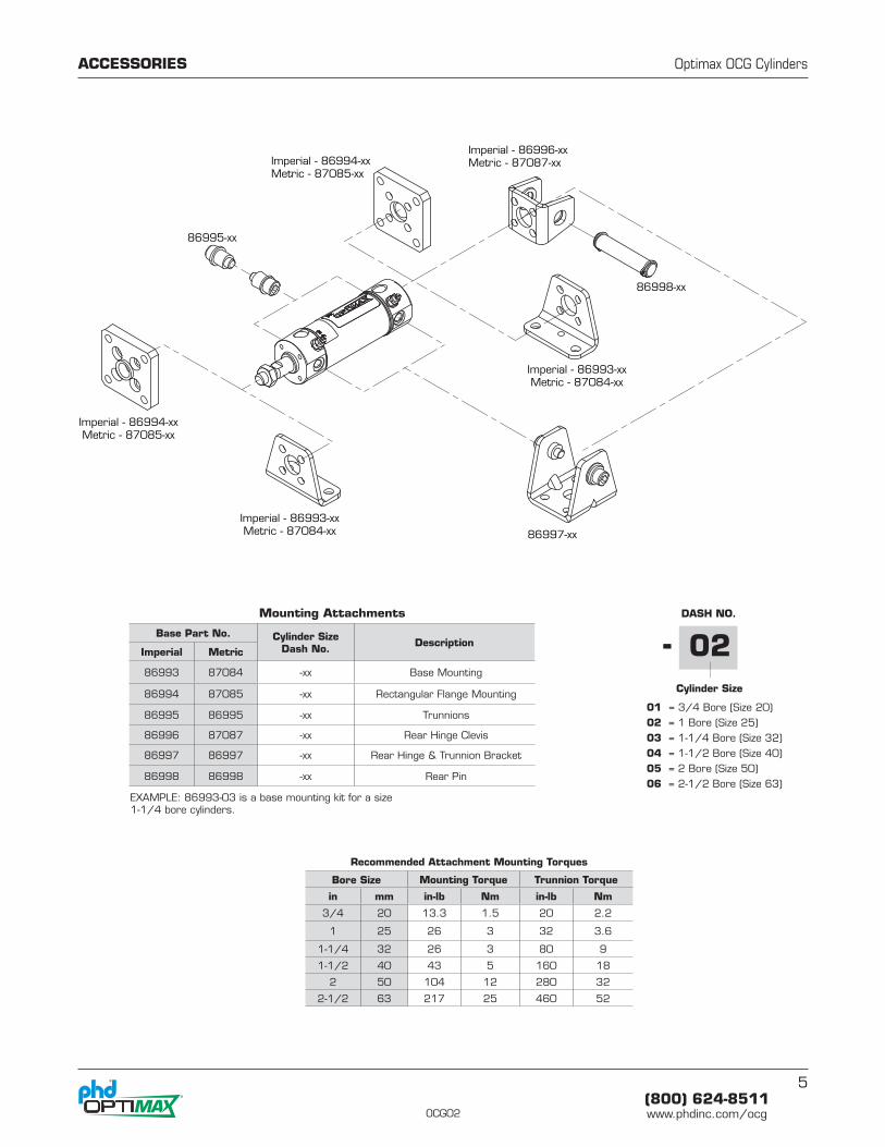
ACCESSORIES Optimax OCG Cylinders
Imperial - 86994-xxMetric - 87085-xx
Imperial - 86994-xxMetric - 87085-xx
Imperial - 86993-xxMetric - 87084-xx
Imperial - 86993-xxMetric - 87084-xx
86995-xx
Imperial - 86996-xxMetric - 87087-xx
86997-xx
86998-xx
Recommended Attachment Mounting Torques
Bore Size Mounting Torque Trunnion Torque
in mm in-lb Nm in-lb Nm
3/4 20 13.3 1.5 20 2.2
1 25 26 3 32 3.6
1-1/4 32 26 3 80 9
1-1/2 40 43 5 160 18
2 50 104 12 280 32
2-1/2 63 217 25 460 52
Base Part No. Cylinder SizeDash No. Description
Imperial Metric
86993 87084 -xx Base Mounting
86994 87085 -xx Rectangular Flange Mounting
86995 86995 -xx Trunnions
86996 87087 -xx Rear Hinge Clevis
86997 86997 -xx Rear Hinge & Trunnion Bracket
86998 86998 -xx Rear Pin
DASH NO.
01 = 3/4 Bore (Size 20)02 = 1 Bore (Size 25)03 = 1-1/4 Bore (Size 32)04 = 1-1/2 Bore (Size 40)05 = 2 Bore (Size 50)06 = 2-1/2 Bore (Size 63)
Cylinder Size
02-Mounting Attachments
EXAMPLE: 86993-03 is a base mounting kit for a size 1-1/4 bore cylinders.
6(800) 624-8511www.phdinc.com/ocg OCG02
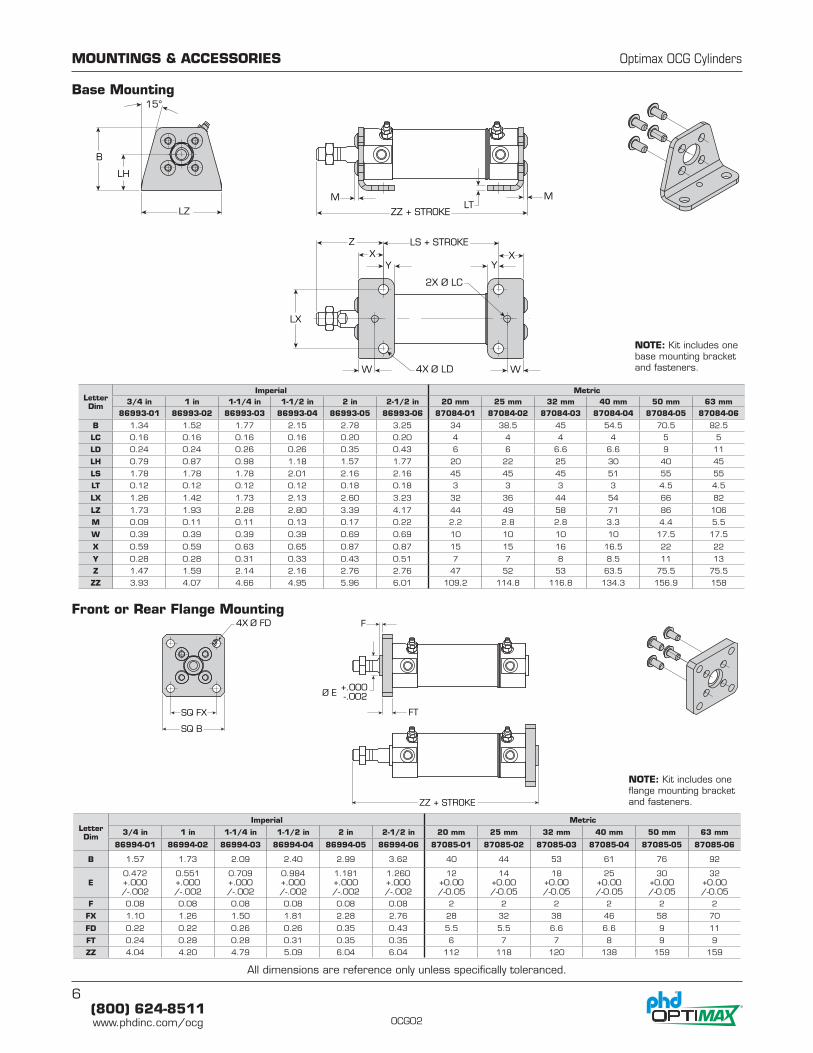
Letter Dim
Imperial Metric3/4 in 1 in 1-1/4 in 1-1/2 in 2 in 2-1/2 in 20 mm 25 mm 32 mm 40 mm 50 mm 63 mm
86993-01 86993-02 86993-03 86993-04 86993-05 86993-06 87084-01 87084-02 87084-03 87084-04 87084-05 87084-06
B 1.34 1.52 1.77 2.15 2.78 3.25 34 38.5 45 54.5 70.5 82.5
LC 0.16 0.16 0.16 0.16 0.20 0.20 4 4 4 4 5 5
LD 0.24 0.24 0.26 0.26 0.35 0.43 6 6 6.6 6.6 9 11
LH 0.79 0.87 0.98 1.18 1.57 1.77 20 22 25 30 40 45
LS 1.78 1.78 1.78 2.01 2.16 2.16 45 45 45 51 55 55
LT 0.12 0.12 0.12 0.12 0.18 0.18 3 3 3 3 4.5 4.5
LX 1.26 1.42 1.73 2.13 2.60 3.23 32 36 44 54 66 82
LZ 1.73 1.93 2.28 2.80 3.39 4.17 44 49 58 71 86 106
M 0.09 0.11 0.11 0.13 0.17 0.22 2.2 2.8 2.8 3.3 4.4 5.5
W 0.39 0.39 0.39 0.39 0.69 0.69 10 10 10 10 17.5 17.5
X 0.59 0.59 0.63 0.65 0.87 0.87 15 15 16 16.5 22 22
Y 0.28 0.28 0.31 0.33 0.43 0.51 7 7 8 8.5 11 13
Z 1.47 1.59 2.14 2.16 2.76 2.76 47 52 53 63.5 75.5 75.5
ZZ 3.93 4.07 4.66 4.95 5.96 6.01 109.2 114.8 116.8 134.3 156.9 158
Letter Dim
Imperial Metric
3/4 in 1 in 1-1/4 in 1-1/2 in 2 in 2-1/2 in 20 mm 25 mm 32 mm 40 mm 50 mm 63 mm
86994-01 86994-02 86994-03 86994-04 86994-05 86994-06 87085-01 87085-02 87085-03 87085-04 87085-05 87085-06
B 1.57 1.73 2.09 2.40 2.99 3.62 40 44 53 61 76 92
E0.472+.000 /-.002
0.551+.000 /-.002
0.709+.000 /-.002
0.984+.000 /-.002
1.181+.000 /-.002
1.260+.000 /-.002
12+0.00 /-0.05
14+0.00 /-0.05
18+0.00 /-0.05
25+0.00 /-0.05
30+0.00 /-0.05
32+0.00 /-0.05
F 0.08 0.08 0.08 0.08 0.08 0.08 2 2 2 2 2 2
FX 1.10 1.26 1.50 1.81 2.28 2.76 28 32 38 46 58 70
FD 0.22 0.22 0.26 0.26 0.35 0.43 5.5 5.5 6.6 6.6 9 11
FT 0.24 0.28 0.28 0.31 0.35 0.35 6 7 7 8 9 9
ZZ 4.04 4.20 4.79 5.09 6.04 6.04 112 118 120 138 159 159
MOUNTINGS & ACCESSORIES Optimax OCG Cylinders
Base Mounting
Front or Rear Flange Mounting
B
LH
LX
X
W
ZZ + STROKE
LS + STROKEX
W
MM
Z
LZ
Ø LD4X
15°
Ø LC2X
LT
YY
SQ FX
SQ B
FT
F
Ø E+.000-.002
ZZ + STROKE
Ø FD4X
NOTE: Kit includes one base mounting bracket and fasteners.
NOTE: Kit includes one flange mounting bracket and fasteners.
All dimensions are reference only unless specifically toleranced.
7(800) 624-8511www.phdinc.com/ocgOCG02
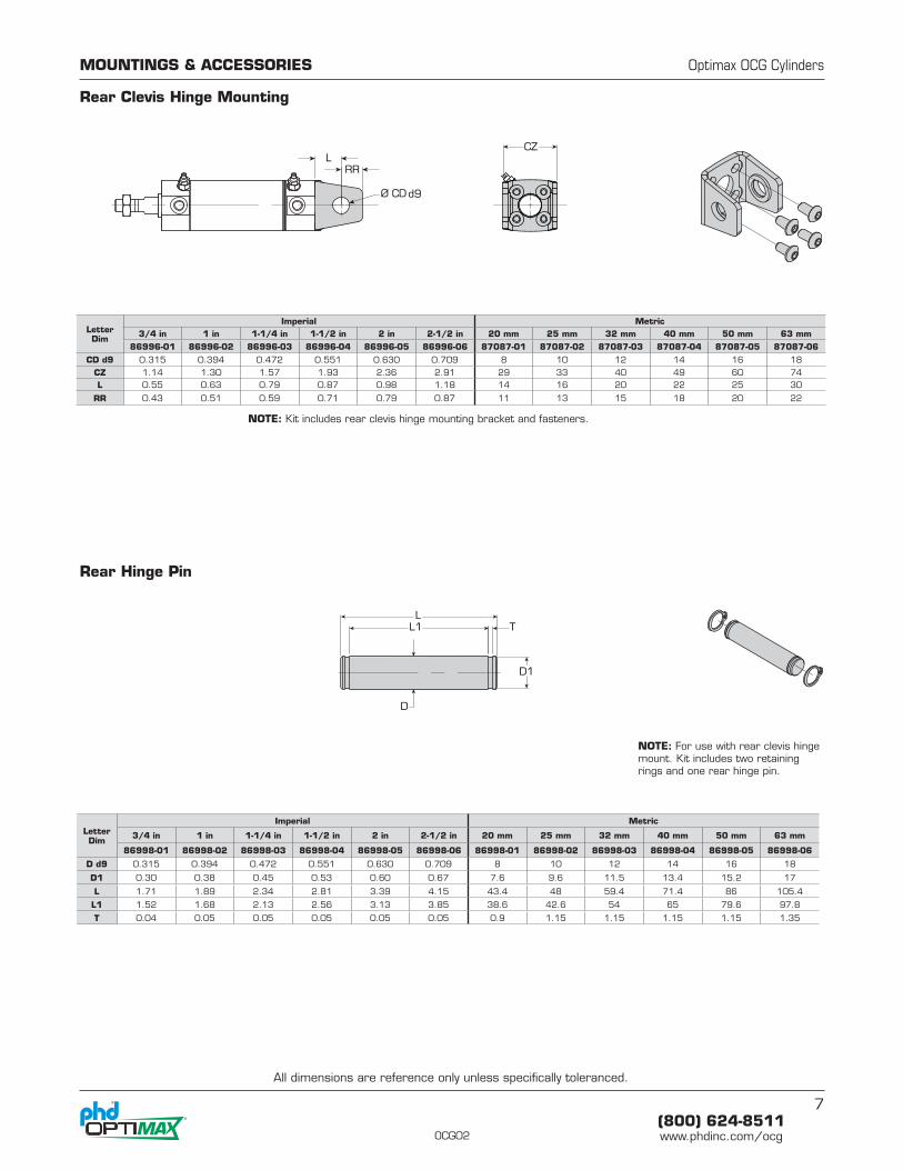
Rear Clevis Hinge Mounting
MOUNTINGS & ACCESSORIES Optimax OCG Cylinders
LCZ
Ø CDd9
RR
Letter Dim
Imperial Metric3/4 in 1 in 1-1/4 in 1-1/2 in 2 in 2-1/2 in 20 mm 25 mm 32 mm 40 mm 50 mm 63 mm
86996-01 86996-02 86996-03 86996-04 86996-05 86996-06 87087-01 87087-02 87087-03 87087-04 87087-05 87087-06
CD d9 0.315 0.394 0.472 0.551 0.630 0.709 8 10 12 14 16 18
CZ 1.14 1.30 1.57 1.93 2.36 2.91 29 33 40 49 60 74L 0.55 0.63 0.79 0.87 0.98 1.18 14 16 20 22 25 30
RR 0.43 0.51 0.59 0.71 0.79 0.87 11 13 15 18 20 22
NOTE: Kit includes rear clevis hinge mounting bracket and fasteners.
Rear Hinge Pin
Letter Dim
Imperial Metric
3/4 in 1 in 1-1/4 in 1-1/2 in 2 in 2-1/2 in 20 mm 25 mm 32 mm 40 mm 50 mm 63 mm
86998-01 86998-02 86998-03 86998-04 86998-05 86998-06 86998-01 86998-02 86998-03 86998-04 86998-05 86998-06
D d9 0.315 0.394 0.472 0.551 0.630 0.709 8 10 12 14 16 18
D1 0.30 0.38 0.45 0.53 0.60 0.67 7.6 9.6 11.5 13.4 15.2 17
L 1.71 1.89 2.34 2.81 3.39 4.15 43.4 48 59.4 71.4 86 105.4
L1 1.52 1.68 2.13 2.56 3.13 3.85 38.6 42.6 54 65 79.6 97.8
T 0.04 0.05 0.05 0.05 0.05 0.05 0.9 1.15 1.15 1.15 1.15 1.35
LL1 T
D
D1
NOTE: For use with rear clevis hinge mount. Kit includes two retaining rings and one rear hinge pin.
All dimensions are reference only unless specifically toleranced.
8(800) 624-8511www.phdinc.com/ocg OCG02
4M 2/15 9651
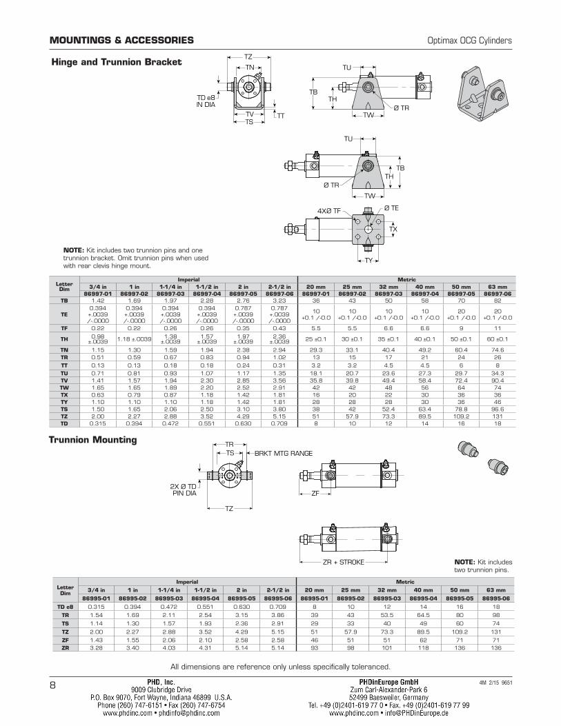
MOUNTINGS & ACCESSORIES Optimax OCG Cylinders
Trunnion Mounting
2X Ø TDPIN DIA
TSTR
BRKT MTG RANGE
TZ
ZF
ZR + STROKE
Letter Dim
Imperial Metric
3/4 in 1 in 1-1/4 in 1-1/2 in 2 in 2-1/2 in 20 mm 25 mm 32 mm 40 mm 50 mm 63 mm
86995-01 86995-02 86995-03 86995-04 86995-05 86995-06 86995-01 86995-02 86995-03 86995-04 86995-05 86995-06
TD e8 0.315 0.394 0.472 0.551 0.630 0.709 8 10 12 14 16 18
TR 1.54 1.69 2.11 2.54 3.15 3.86 39 43 53.5 64.5 80 98
TS 1.14 1.30 1.57 1.93 2.36 2.91 29 33 40 49 60 74
TZ 2.00 2.27 2.88 3.52 4.29 5.15 51 57.9 73.3 89.5 109.2 131
ZF 1.43 1.55 2.06 2.10 2.58 2.58 46 51 51 62 71 71ZR 3.28 3.40 4.03 4.31 5.14 5.14 93 98 101 118 136 136
NOTE: Kit includes two trunnion pins.
All dimensions are reference only unless specifically toleranced.
Hinge and Trunnion Bracket
Letter Dim
Imperial Metric3/4 in 1 in 1-1/4 in 1-1/2 in 2 in 2-1/2 in 20 mm 25 mm 32 mm 40 mm 50 mm 63 mm
86997-01 86997-02 86997-03 86997-04 86997-05 86997-06 86997-01 86997-02 86997-03 86997-04 86997-05 86997-06TB 1.42 1.69 1.97 2.28 2.76 3.23 36 43 50 58 70 82
TE0.394+.0039 /-.0000
0.394+.0039 /-.0000
0.394+.0039 /-.0000
0.394+.0039 /-.0000
0.787+.0039 /-.0000
0.787+.0039 /-.0000
10+0.1 /-0.0
10+0.1 /-0.0
10+0.1 /-0.0
10+0.1 /-0.0
20+0.1 /-0.0
20+0.1 /-0.0
TF 0.22 0.22 0.26 0.26 0.35 0.43 5.5 5.5 6.6 6.6 9 11
TH 0.98±.0039 1.18 ±.0039 1.38
±.00391.57
±.00391.97
±.00392.36
±.0039 25 ±0.1 30 ±0.1 35 ±0.1 40 ±0.1 50 ±0.1 60 ±0.1
TN 1.15 1.30 1.59 1.94 2.38 2.94 29.3 33.1 40.4 49.2 60.4 74.6TR 0.51 0.59 0.67 0.83 0.94 1.02 13 15 17 21 24 26
TT 0.13 0.13 0.18 0.18 0.24 0.31 3.2 3.2 4.5 4.5 6 8
TU 0.71 0.81 0.93 1.07 1.17 1.35 18.1 20.7 23.6 27.3 29.7 34.3TV 1.41 1.57 1.94 2.30 2.85 3.56 35.8 39.8 49.4 58.4 72.4 90.4TW 1.65 1.65 1.89 2.20 2.52 2.91 42 42 48 56 64 74TX 0.63 0.79 0.87 1.18 1.42 1.81 16 20 22 30 36 36TY 1.10 1.10 1.10 1.18 1.42 1.81 28 28 28 30 36 46TS 1.50 1.65 2.06 2.50 3.10 3.80 38 42 52.4 63.4 78.8 96.6TZ 2.00 2.27 2.88 3.52 4.29 5.15 51 57.9 73.3 89.5 109.2 131TD 0.315 0.394 0.472 0.551 0.630 0.709 8 10 12 14 16 18
TN
TZ
Ø TD e8PIN DIA
TSTV
TX
TY
TW
TT
Ø TF4X Ø TE
THTB
TU
Ø TR
TB
TU
TH
TWØ TR
NOTE: Kit includes two trunnion pins and one trunnion bracket. Omit trunnion pins when used with rear clevis hinge mount.