Embed Size (px)
Citation preview
The ‘Ham Can’ or Philips 930A
NZVRS BULLETIN
Vol 31 No 2 May 2010
NEW ZEALAND VINTAGE RADIO SOCIETY INC. A non-profit organisation devoted to the preservation of early radio equipment and associated
historical information.
Postal address - PO Box 13 873, Onehunga, Auckland 1643.
Web site: - http://www.nzvrs.pl.net Email address: - [email protected]
PRESIDENT: Ian Sangster, 75 Anawata Road, R.D.2, New Lynn, Auckland 0772 Phone: 09-814 9597 or 027 227 0426 Email: [email protected]
SECRETARY: Paul Woodcock, 2 Levy Road, Glen Eden, Auckland. Phone: 09-818 4740 Email: [email protected] Paul handles general correspondence and requests for purchase of books and badges.
TREASURER: David Crozier, P.O. Box 13 873, Onehunga, Auckland 1643. Phone: 09-636 5954 or 027 230 6889 Email: [email protected] David handles editorial, financial and membership matters. A list of members is available on application with a stamped, self-addressed envelope for the personal use of members only. Please address all NZVRS monies to P.O. Box 13 873, Onehunga, Auckland 1643, N.Z.
NZVRS LIBRARY The NZVRS librarian is Ross Paton with assistance from Bruce Churcher. There is a lot of work to do before full member service is restored but requests may be forwarded to the NZVRS office (postal address at the top of this page) or Email; [email protected]
NZVRS BULLETIN is a subscription magazine for members, published quarterly in the months of February, May, August and November. Opinions expressed by writers are not necessarily those of the Society. Contributions, letters, etc can be sent to:
THE EDITORIAL TEAM, Ian Sangster, 75 Anawhata Rd, R.D.2. New Lynn 0772 or David Crozier, P.O. Box 13873, Onehunga, Auckland 1643. Email: [email protected]
A Calendar of Events is listed on our website at www.nzvrs.pl.net/aaa/calendar
NZVRS Display Queens Birthday weekend
5-7 June at the Alexander Park raceway in conjunction with the NZART Convention. Public day will be on Saturday 5 June 2010.
NZVRS AGM will be held on Saturday 3
July 2010 at the Auckland clubrooms. Details to be included in the May bulletin.
AUCKLAND MEETINGS are held at the Horticultural Society Hall, 990 Great North Road (opposite Motions Road.) Western Springs, on the third Monday of the month from 7.30pm. July: Monday 19 Inductors night August: Monday 16 Auction night September: Monday 20 Military night October: Monday 18 Auction night
TARANAKI AREA MEETINGS are held on the second Sunday in even months. Visitors are most welcome; contact either Bill Campbell, Phone 06-753 2475 or Graeme Lea, Phone 06-758 5344
WELLINGTON MEETINGS are held typically from 1pm on the second Sunday of every month at Tireti Hall, Te Pene Ave, Titahi Bay. For details contact Bob Hatton, 40 Rose St, Wadestown. Phone: 04-472 8788.
CHRISTCHURCH MEETINGS are held on the first Tuesday of odd months at the Christchurch West Radio Clubrooms "Auburn Park", 333 Riccarton Road. For further details contact Jim Lovell, 41 Yardley St, Avonhead, Christchurch 8004. Phone 03-342 7760
The subscription year is a calendar year (1 January – 31 Dec). Subscription renewal slips are sent in the November Bulletin with reminders in the February issue. NZ Rate is $25; $20 renewal before 15 March, $25 after.
NZVRS © COPYRIGHT 2010
2
EDITORIAL
A brief message about the AGM on Saturday 3 July seems appropriate. Generally the format will be the same as previous years; trading tables from 10 am, noon closure time for the restoration competition (before and after photos with short story), 1pm AGM starts then followed by the afternoon auction. A stuffer should be included with this bulletin.
Television New Zealand has recently celebrated the 50th anniversary of their start in TV transmissions. Our November 2007 bulletin had some background material on the various developments and early demonstrations of (closed circuit) television around NZ. Perhaps the PYE works, 1954 outside broadcast of the Harlequins and Barbarians match at Waihi’s Rugby Park to local sets and hospital can be considered an NZ TV first. The rest they say is history! Speaking of which, there are a couple of queries in this bulletin – people seeking information on the Bearing Head radio masts/station and the operator in the ZLW photo. Your assistance, as always, is appreciated. May see you at the AGM perhaps! Cheers, David Crozier
Cover Picture:
The ‘Ham Can’ or Philips 930A is
an iconic set for some. One of the
early Philips sets to come to New
Zealand in 1932 and at an
‘affordable price’ of 15 pounds. Its
‘British Made’ branding ensured it
found its way into many NZ homes
and hearts.
NEW MEMBERS: N Bovin Christchurch
K Briggs Waikato
NZVRS Bulletin
P.O. Box 13 873, Onehunga,
Auckland 1643
Email: [email protected]
A reminder that the AGM competition is
still open for member’s “restoration
project” – just supply before and after
photos, along with some comments on a
recent project, received before noon at
the AGM, Saturday 3 July. The PO Box
will be cleared Saturday morning. The
winner will receive a complimentary
subscription for the 2011 year.
CONTENTS
Correspondence etc 4 Bearing Head Lighthouse query
A Quad Fault with a difference 7 Don Beswick with some insights
Southern Sopundings 10 The Christchurch Chapter
A Tale of Two Sets 11
Bill Campbell finds some twins
Centrefold 16 Some pics from the South Pole
An EZ41 Clipper variation 18
Things are not always wot they seem
The Philips 930A 22
More than a Spam Can
The ZLW Picture 29
Can you help identify the operator?
More from Murphy 30
Laws relating to servicing sets
USUAL FEATURES:
Marketplace 31
3
Bearing Head Radio Station facility –
from [email protected]
Please see attached photo [opposite] of the radio facility at Baring Head Wellington established 1937.
Would there be anyone in the Society who might know anything about the radio operation at Baring
Head at any stage, such as the type of antenna that was erected on the two masts and what operational
frequencies were used there and what kind of radios were used?
I do hope someone may know something about this. With my sincere best wishes. Foss Leach ZL2JKP
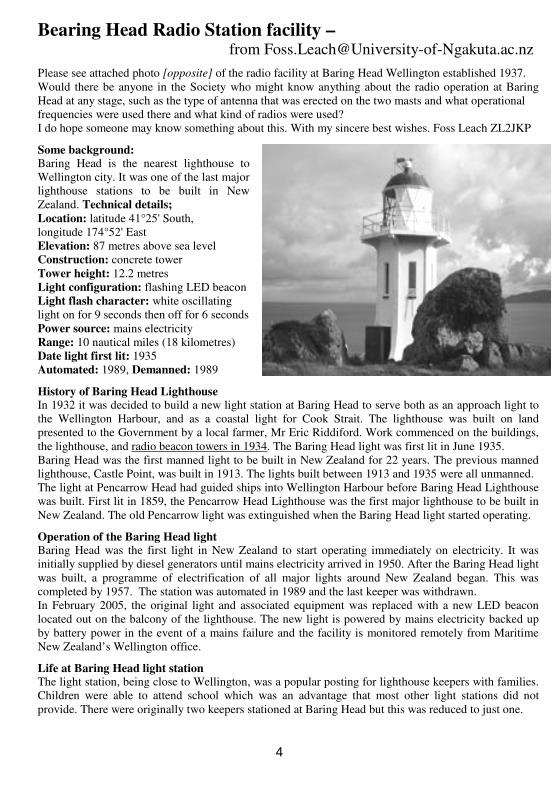
Some background: Baring Head is the nearest lighthouse to
Wellington city. It was one of the last major
lighthouse stations to be built in New
Zealand. Technical details;
Location: latitude 41°25' South,
longitude 174°52' East
Elevation: 87 metres above sea level
Construction: concrete tower
Tower height: 12.2 metres
Light configuration: flashing LED beacon
Light flash character: white oscillating
light on for 9 seconds then off for 6 seconds
Power source: mains electricity
Range: 10 nautical miles (18 kilometres)
Date light first lit: 1935
Automated: 1989, Demanned: 1989
History of Baring Head Lighthouse In 1932 it was decided to build a new light station at Baring Head to serve both as an approach light to
the Wellington Harbour, and as a coastal light for Cook Strait. The lighthouse was built on land
presented to the Government by a local farmer, Mr Eric Riddiford. Work commenced on the buildings,
the lighthouse, and radio beacon towers in 1934. The Baring Head light was first lit in June 1935.
Baring Head was the first manned light to be built in New Zealand for 22 years. The previous manned
lighthouse, Castle Point, was built in 1913. The lights built between 1913 and 1935 were all unmanned.
The light at Pencarrow Head had guided ships into Wellington Harbour before Baring Head Lighthouse
was built. First lit in 1859, the Pencarrow Head Lighthouse was the first major lighthouse to be built in
New Zealand. The old Pencarrow light was extinguished when the Baring Head light started operating.
Operation of the Baring Head light Baring Head was the first light in New Zealand to start operating immediately on electricity. It was
initially supplied by diesel generators until mains electricity arrived in 1950. After the Baring Head light
was built, a programme of electrification of all major lights around New Zealand began. This was
completed by 1957. The station was automated in 1989 and the last keeper was withdrawn.
In February 2005, the original light and associated equipment was replaced with a new LED beacon
located out on the balcony of the lighthouse. The new light is powered by mains electricity backed up
by battery power in the event of a mains failure and the facility is monitored remotely from Maritime
New Zealand’s Wellington office.
Life at Baring Head light station The light station, being close to Wellington, was a popular posting for lighthouse keepers with families.
Children were able to attend school which was an advantage that most other light stations did not
provide. There were originally two keepers stationed at Baring Head but this was reduced to just one.
4
Baring Head Lighthouse was used as a signal station by the armed forces during the Second World War.
Light keepers were exempt from conscription because their work contributed to the war effort. Keepers
were issued with army jerseys to counter the extreme weather conditions under which they worked.
See; www.teara.govt.nz/en/lighthouses
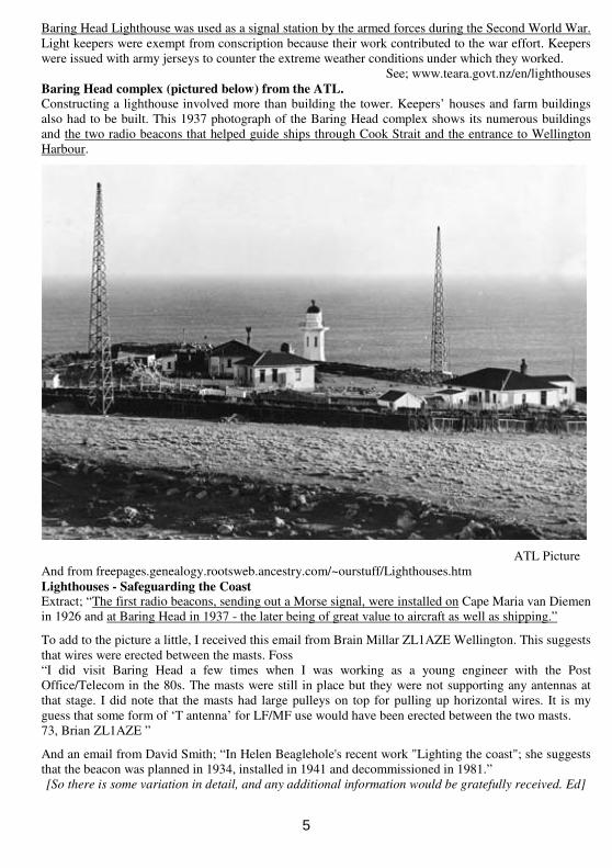
Baring Head complex (pictured below) from the ATL.
Constructing a lighthouse involved more than building the tower. Keepers’ houses and farm buildings
also had to be built. This 1937 photograph of the Baring Head complex shows its numerous buildings
and the two radio beacons that helped guide ships through Cook Strait and the entrance to Wellington
Harbour.
ATL Picture
And from freepages.genealogy.rootsweb.ancestry.com/~ourstuff/Lighthouses.htm
Lighthouses - Safeguarding the Coast Extract; “The first radio beacons, sending out a Morse signal, were installed on Cape Maria van Diemen
in 1926 and at Baring Head in 1937 - the later being of great value to aircraft as well as shipping.”
To add to the picture a little, I received this email from Brain Millar ZL1AZE Wellington. This suggests
that wires were erected between the masts. Foss
“I did visit Baring Head a few times when I was working as a young engineer with the Post
Office/Telecom in the 80s. The masts were still in place but they were not supporting any antennas at
that stage. I did note that the masts had large pulleys on top for pulling up horizontal wires. It is my
guess that some form of ‘T antenna’ for LF/MF use would have been erected between the two masts.
73, Brian ZL1AZE ”
And an email from David Smith; “In Helen Beaglehole's recent work "Lighting the coast"; she suggests
that the beacon was planned in 1934, installed in 1941 and decommissioned in 1981.”
[So there is some variation in detail, and any additional information would be gratefully received. Ed]
5
An Unusual Fault in a QUAD 33 Preamplifier.
From Don Beswick
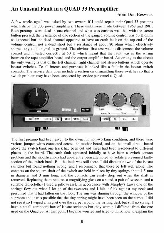
A few weeks ago I was asked by two owners if I could repair their Quad 33 preamps
which drive the 303 power amplifiers. These units were made between 1968 and 1981.
Both preamps were dead in one channel and what was curious was that with the stereo
button pressed, the resistance of one section of the ganged volume control was 50 K ohms
as expected but the dead channel appeared to have an earth fault on the top end of the
volume control, not a dead short but a resistance of about 80 ohms which effectively
shorted any audio signal to ground. The obvious first test was to disconnect the volume
control and it tested correctly at 50 K which meant that the fault was in the wiring
between the tape amplifier board and the output amplifier board. According to the circuit
the only wiring is that of the left channel, right channel and stereo buttons which operate
isostat switches. To all intents and purposes it looked like a fault in the isostat switch
contacts. The service data does include a section on dismantling these switches so that a
switch problem may have been suspected by service personnel at Quad.
The first preamp had been given to the owner in non-working condition, and there were
various jumper wires connected across the mother board, and on the small circuit board
above the switch bank one track had been cut and wires had been resoldered to different
places on the board. The earth fault appeared initially to have been a switch contact
problem and the modifications had apparently been attempted to isolate a presumed faulty
section of the switch bank. But the fault was still there. I did dismantle two of the isostat
switches but found nothing wrong, and I recommend that these be left well alone. The
contacts on the square shaft of the switch are held in place by tiny springs about 1.5 mm
in diameter and 3 mm long, and the contacts can easily drop out when the shaft is
removed. Replacing them requires a magnifying glass on a stand, a pair of tweezers and a
suitable tablecloth. (I used a pillowcase). In accordance with Murphy's Laws one of the
springs flew out when I let go of the tweezers and I felt it flick against my neck and
presumed that it had fallen on the floor. The sun was shining through the window of the
sunroom and it was possible that the tiny spring might have been seen on the carpet. I did
not see it so I wiped a magnet over the carpet around the writing desk but still no spring. I
have a small cardboard box of isostat switches but they were all different from the one
used on the Quad 33. At that point I became worried and tried to think how to explain the
6
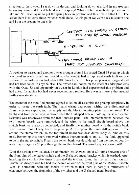
situation to the owner. I sat down in despair and looking down at a fold in my trousers
below my waist and lo and behold – a tiny spring! What a relief, somebody up there must
like me. So I tried again to put the spring back in position and this time it fitted OK. The
lesson here is to leave these switches well alone. At this point we were back to square one
and I put the preamp to one side.
A week or so passed and another owner brought around his prized Quad 33 preamp which
was dead in one channel and would you believe, it had an apparent earth fault on one
section of the volume control, about 80 ohms to earth. This preamp was all original and
had not been taken to anyone else. The owner had looked on the internet under problems
with the Quad 33 and apparently an owner in London had experienced this problem and
had asked for advice but had never received any replies. Here was a mystery that needed
further investigation.
The owner of the modified preamp agreed to let me disassemble the preamp completely in
order to locate the earth fault. The mains wiring and output wiring were disconnected
from the power supply, and the supply and the black mounting plate were removed. The
knobs and front panel were removed then the U-shaped bracket holding the seven isostat
switches was unscrewed from the front chassis panel. The interconnections between the
two mother boards were removed, and the wires to the small circuit board above the
switch bank were also disconnected, and finally the mother board with the switch bank
was removed completely from the preamp. At this point the fault still appeared to be
around the stereo switch, so the top circuit board was desoldered (only 29 pins on this
one). Removing this board removed various interconnections and still the fault appeared
to be in the stereo switch. Finally the switch bank was desoldered from the mother board –
now major surgery - 50 pins through the mother board. The novelty quickly wore off!
With the switch now isolated, an ohmmeter test showed about 80 ohms between one of
the front pins of the stereo switch and the U-shaped metal bracket which is earthed. After
handling the switch a few times I repeated the test and found that the earth fault on this
switch had disappeared but had reappeared on one of the front pins of the Radio-2 switch.
What is noticeable with this model of switch is that there is barely a millimetre of
clearance between the front pins of the switches and the U-shaped metal bracket.
7
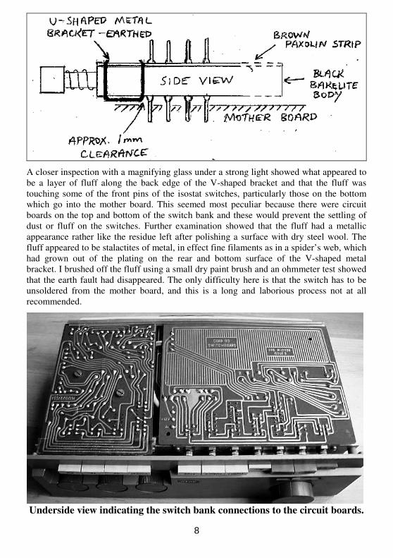
A closer inspection with a magnifying glass under a strong light showed what appeared to
be a layer of fluff along the back edge of the V-shaped bracket and that the fluff was
touching some of the front pins of the isostat switches, particularly those on the bottom
which go into the mother board. This seemed most peculiar because there were circuit
boards on the top and bottom of the switch bank and these would prevent the settling of
dust or fluff on the switches. Further examination showed that the fluff had a metallic
appearance rather like the residue left after polishing a surface with dry steel wool. The
fluff appeared to be stalactites of metal, in effect fine filaments as in a spider’s web, which
had grown out of the plating on the rear and bottom surface of the V-shaped metal
bracket. I brushed off the fluff using a small dry paint brush and an ohmmeter test showed
that the earth fault had disappeared. The only difficulty here is that the switch has to be
unsoldered from the mother board, and this is a long and laborious process not at all
recommended.
Underside view indicating the switch bank connections to the circuit boards.
8
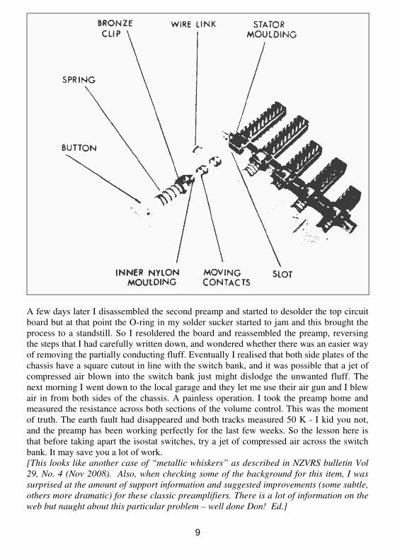
A few days later I disassembled the second preamp and started to desolder the top circuit
board but at that point the O-ring in my solder sucker started to jam and this brought the
process to a standstill. So I resoldered the board and reassembled the preamp, reversing
the steps that I had carefully written down, and wondered whether there was an easier way
of removing the partially conducting fluff. Eventually I realised that both side plates of the
chassis have a square cutout in line with the switch bank, and it was possible that a jet of
compressed air blown into the switch bank just might dislodge the unwanted fluff. The
next morning I went down to the local garage and they let me use their air gun and I blew
air in from both sides of the chassis. A painless operation. I took the preamp home and
measured the resistance across both sections of the volume control. This was the moment
of truth. The earth fault had disappeared and both tracks measured 50 K - I kid you not,
and the preamp has been working perfectly for the last few weeks. So the lesson here is
that before taking apart the isostat switches, try a jet of compressed air across the switch
bank. It may save you a lot of work.
[This looks like another case of “metallic whiskers” as described in NZVRS bulletin Vol
29, No. 4 (Nov 2008). Also, when checking some of the background for this item, I was
surprised at the amount of support information and suggested improvements (some subtle,
others more dramatic) for these classic preamplifiers. There is a lot of information on the
web but naught about this particular problem – well done Don! Ed.]
9
Southern Soundings. From Pete Ingram
The usual twenty odd members turned up for the AGM night on Tuesday 2nd March and quickly
propelled Jim Lovell (chairman), David Chapple (secretary) and Albert Smith (treasurer) back into
their respective jobs that they might have been trying to escape from. Fortunately, they took it all in
good part and 2010 is truly launched.
We had the pleasure of Aucklander David Crozier as guest speaker to let us know how things are
going up north. In a useful ten point discussion, such items as the future of the VRS library, branch
activities in general, value for annual subscription, the workload involved with the bulletin, current
membership numbers (340) and national locations (33% in Auckland, 23% Central, 9% Wellington,
22% Southern and 14% offshore.) – and not least, the financial gain of going for free Community
Post to cover our mailings. David was roundly applauded for his ongoing VRS contribution - and on
this occasion no small task in having to fly to Christchurch for the day and then to take the 'red eye'
home at a very late hour.
"Ooohs" and "Ahhhs" at this meeting were for;
John Dodgson: 1955 General Radio bridge capacitance tester that had the bonus of dissipation rate
metering. This piece of equipment was as good as new and by girth and quality, was most likely
intended for laboratory use.
John Walker: a very neat 1952 500kHz - 18 MHz spy radio, a Mk 301 Receiver. Beautifully
compact, so one could possibly swallow it if captured, it came as a bit of surprise when we are only
mostly aware of John's 'heavy metal' collection.
Geoff Edwards: came up with a unique British Western Electric 1924 superhet that consumes VT5
triodes evidently, for two of the five valves were missing. In good condition all over, it will take
little restoration work.
Albert Smith: to the fore again with an excellent piece of workmanship shown on a 1934 Philco
Model 60. Photographs of the original state of things would have caused many to turn aside from
such a project.
David Chapple: with two up - a 1941 Columbus Model 12 and 1945 Columbus Model 14, both
with that just out of the factory look.
Jim Lovell: well, you know our Jim! Out of the CCC rubbish hag came a nice piece of fretworked
'Golden Knight' frontage with the tuning dial cut-out modified to take a profile head and shoulders
shot of Jim, much like one sees on a King George V penny. It will look nice hanging on the wall.
But it was not up for grabs- not even for the raffle!
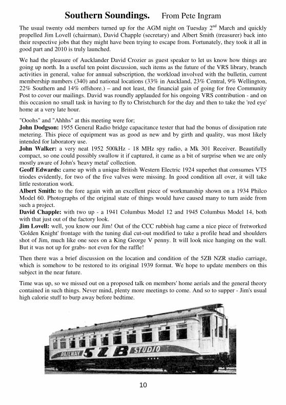
Then there was a brief discussion on the location and condition of the 5ZB NZR studio carriage,
which is somehow to be restored to its original 1939 format. We hope to update members on this
subject in the near future.
Time was up, so we missed out on a proposed talk on members' home aerials and the general theory
contained in such things. Never mind, plenty more meetings to come. And so to supper - Jim's usual
high calorie stuff to burp away before bedtime.
10
A Tale of Two Sets - From Bill Campbell
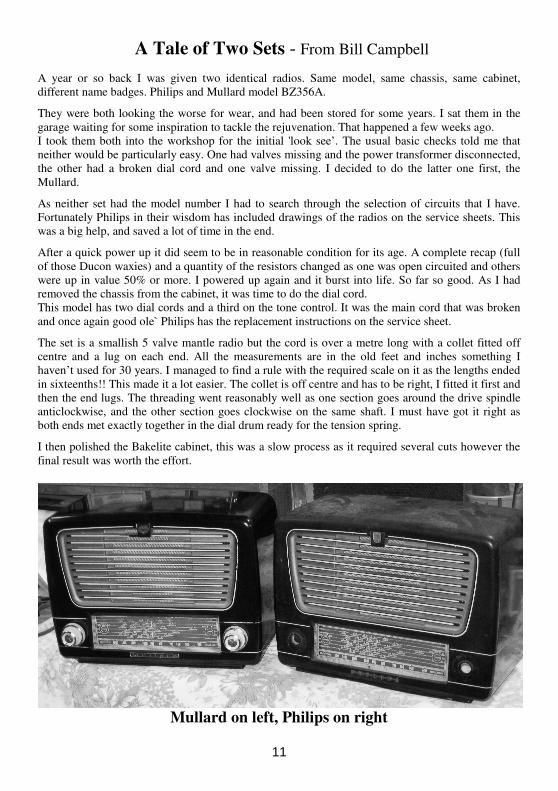
A year or so back I was given two identical radios. Same model, same chassis, same cabinet,
different name badges. Philips and Mullard model BZ356A.
They were both looking the worse for wear, and had been stored for some years. I sat them in the
garage waiting for some inspiration to tackle the rejuvenation. That happened a few weeks ago.
I took them both into the workshop for the initial 'look see’. The usual basic checks told me that
neither would be particularly easy. One had valves missing and the power transformer disconnected,
the other had a broken dial cord and one valve missing. I decided to do the latter one first, the
Mullard.
As neither set had the model number I had to search through the selection of circuits that I have.
Fortunately Philips in their wisdom has included drawings of the radios on the service sheets. This
was a big help, and saved a lot of time in the end.
After a quick power up it did seem to be in reasonable condition for its age. A complete recap (full
of those Ducon waxies) and a quantity of the resistors changed as one was open circuited and others
were up in value 50% or more. I powered up again and it burst into life. So far so good. As I had
removed the chassis from the cabinet, it was time to do the dial cord.
This model has two dial cords and a third on the tone control. It was the main cord that was broken
and once again good ole` Philips has the replacement instructions on the service sheet.
The set is a smallish 5 valve mantle radio but the cord is over a metre long with a collet fitted off
centre and a lug on each end. All the measurements are in the old feet and inches something I
haven’t used for 30 years. I managed to find a rule with the required scale on it as the lengths ended
in sixteenths!! This made it a lot easier. The collet is off centre and has to be right, I fitted it first and
then the end lugs. The threading went reasonably well as one section goes around the drive spindle
anticlockwise, and the other section goes clockwise on the same shaft. I must have got it right as
both ends met exactly together in the dial drum ready for the tension spring.
I then polished the Bakelite cabinet, this was a slow process as it required several cuts however the
final result was worth the effort.
Mullard on left, Philips on right
11
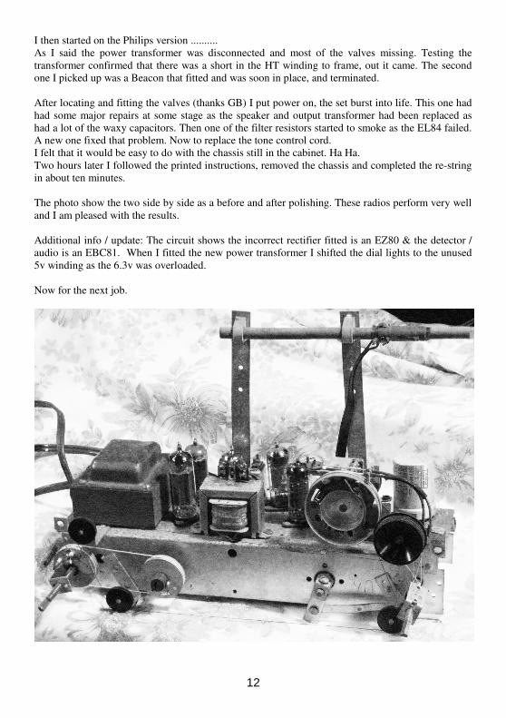
I then started on the Philips version ..........
As I said the power transformer was disconnected and most of the valves missing. Testing the
transformer confirmed that there was a short in the HT winding to frame, out it came. The second
one I picked up was a Beacon that fitted and was soon in place, and terminated.
After locating and fitting the valves (thanks GB) I put power on, the set burst into life. This one had
had some major repairs at some stage as the speaker and output transformer had been replaced as
had a lot of the waxy capacitors. Then one of the filter resistors started to smoke as the EL84 failed.
A new one fixed that problem. Now to replace the tone control cord.
I felt that it would be easy to do with the chassis still in the cabinet. Ha Ha.
Two hours later I followed the printed instructions, removed the chassis and completed the re-string
in about ten minutes.
The photo show the two side by side as a before and after polishing. These radios perform very well
and I am pleased with the results.
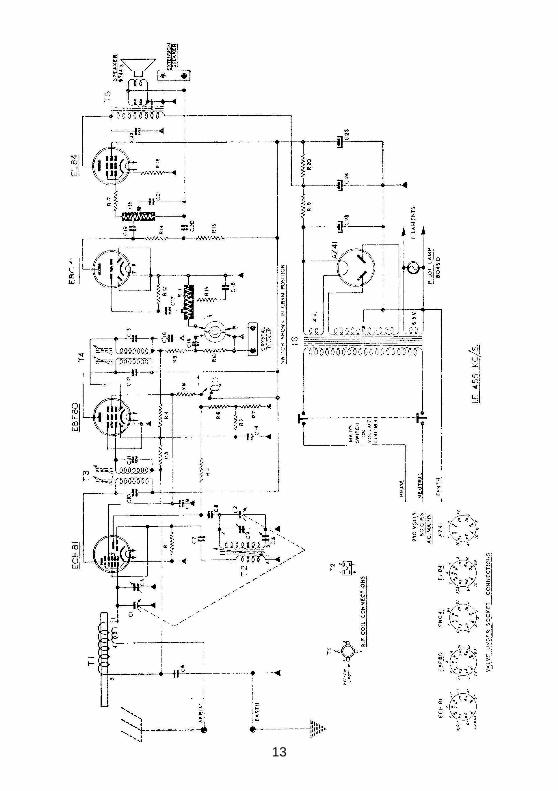
Additional info / update: The circuit shows the incorrect rectifier fitted is an EZ80 & the detector /
audio is an EBC81. When I fitted the new power transformer I shifted the dial lights to the unused
5v winding as the 6.3v was overloaded.
Now for the next job.
12
13
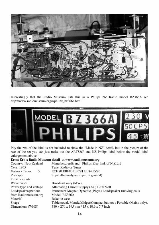
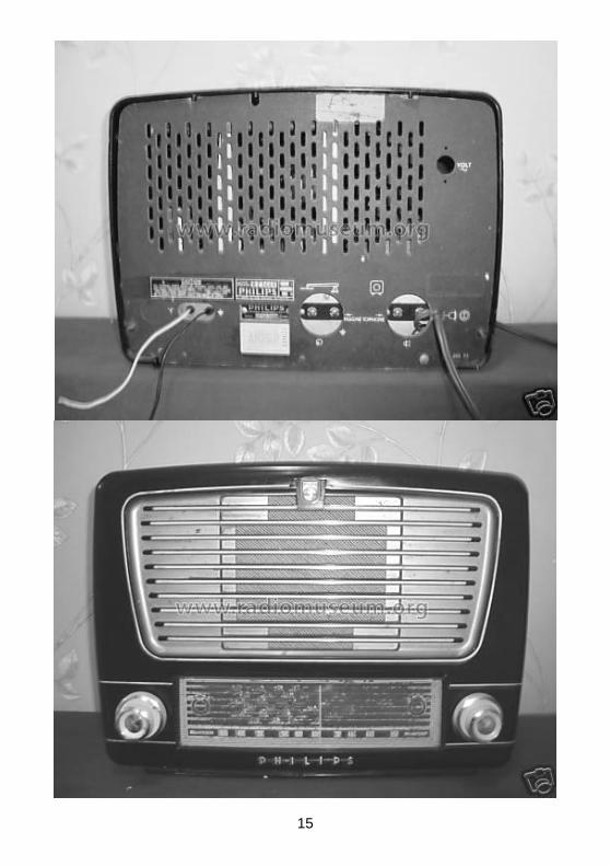
Interestingly that the Radio Museum lists this as a Philips NZ Radio model BZ366A see
http://www.radiomuseum.org/r/philnz_bz366a.html
Pity the rest of the label is not included to show the “Made in NZ” detail, but in the picture of the
rear of the set you can just make out the ARTS&P and NZ Philips label below the model label
enlargement above.
Ernst Erb’s Radio Museum detail at www.radiomuseum.org Country: New Zealand Manufacturer/Brand: Philips Elec. Ind. of N.Z Ltd
Year: 1955 Type: Radio or Tuner
Valves / Tubes 5: ECH80 EBF80 EBC81 EL84 EZ80
Principle Super-Heterodyne (Super in general)
Tuned circuits
Wave bands Broadcast only (MW).
Power type and voltage Alternating Current supply (AC) / 230 Volt
Loudspeaker/pwr.out Permanent Magnet Dynamic (PDyn) Loudspeaker (moving coil)
from Radiomuseum.org Model: BZ366A
Material Bakelite case
Shape Tablemodel, Mantle/Midget/Compact but not a Portable (Mains only).
Dimensions (WHD) 380 x 270 x 195 mm / 15 x 10.6 x 7.7 inch
14
15
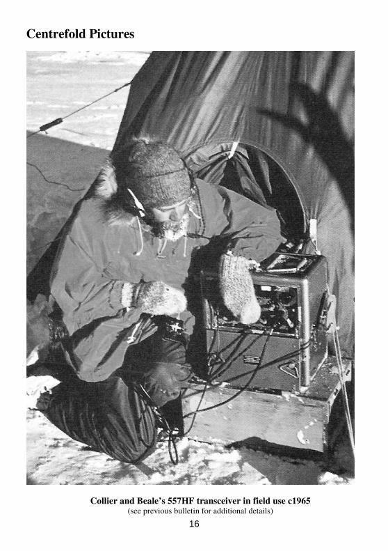
Centrefold Pictures
Collier and Beale’s 557HF transceiver in field use c1965
(see previous bulletin for additional details)
16
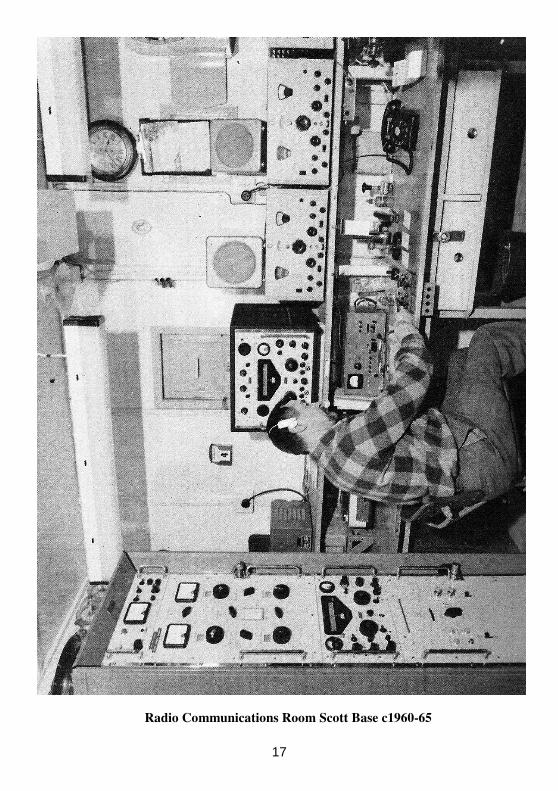
Radio Communications Room Scott Base c1960-65
17
A Clipper Tail from John Roberts "Pentagrid" <[email protected]>
Some people take on challenges and sometimes get surprises – not the least in this story from John;
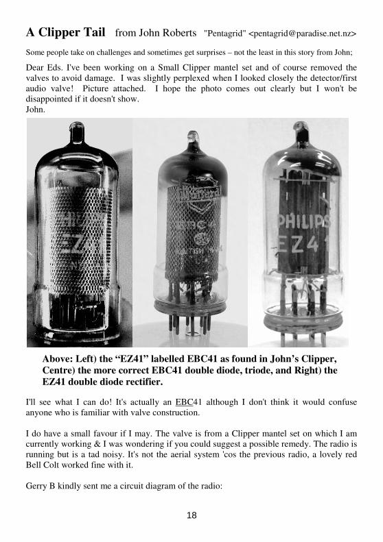
Dear Eds. I've been working on a Small Clipper mantel set and of course removed the
valves to avoid damage. I was slightly perplexed when I looked closely the detector/first
audio valve! Picture attached. I hope the photo comes out clearly but I won't be
disappointed if it doesn't show.
John.
Above: Left) the “EZ41” labelled EBC41 as found in John’s Clipper,
Centre) the more correct EBC41 double diode, triode, and Right) the
EZ41 double diode rectifier.
I'll see what I can do! It's actually an EBC41 although I don't think it would confuse
anyone who is familiar with valve construction.
I do have a small favour if I may. The valve is from a Clipper mantel set on which I am
currently working & I was wondering if you could suggest a possible remedy. The radio is
running but is a tad noisy. It's not the aerial system 'cos the previous radio, a lovely red
Bell Colt worked fine with it.
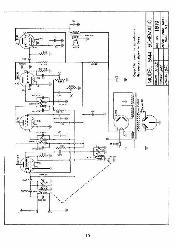
Gerry B kindly sent me a circuit diagram of the radio:
18
19
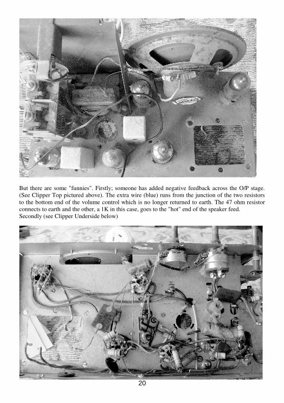
But there are some "funnies". Firstly; someone has added negative feedback across the O/P stage.
(See Clipper Top pictured above). The extra wire (blue) runs from the junction of the two resistors
to the bottom end of the volume control which is no longer returned to earth. The 47 ohm resistor
connects to earth and the other, a 1K in this case, goes to the "hot" end of the speaker feed.
Secondly (see Clipper Underside below)
20
There is a 8.2K resistor between the 220K grid leak/.005uF coupling capacitor & the grid of the
EL41 - a grid stopper?
And thirdly, the 10pF capacitor across the aerial transformer is missing.
I bought three Clippers & all have these modifications/omissions & they look original, so I think
these are meant to be that way. All doubtful resistors have been replaced along with all the electros
& waxed beasties. I have left the red mica, (I think), caps alone 'cos in my experience, these rarely
give trouble. The mains transformer is out 'cos I took it to work, to test it on the megger there.
Anyway, the bit which is confusing me is the high hash. I've lined the set up as per the instructions
in Radio & Hobbies & this improved things a bit. I have added the 10pF across the aerial coil,
swapped out the ECH42 & EF41 but to no avail - it's still noisy. Any advice you could give would
be very very much appreciated
I am very happy to write this up for the bulletin - maybe use this correspondence as a start point? &
am happy to have any assumptions I have made, corrected if needs be. I want to learn :)
Yours sincerely,
John Roberts.
The Handee Miniature Tube Puller
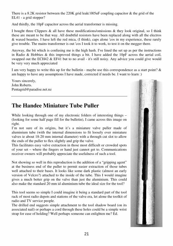
While looking through one of my electronic folders of interesting things –
(looking for some half page fill for the bulletin), I came across this image on
right.
I’m not sure of its origins, but it’s a miniature valve puller made of
aluminium tube (with the internal dimensions to fit loosely over miniature
valves ie about 18-20 mm internal diameter) with a through cut slot to allow
the ends of the puller to flex slightly and grip the valve.
This facilitates easy valve extraction in those most difficult or crowded spots
of your set – where the fingers or hand just cannot get to. Communications
receiver owners will probably appreciate the usefulness of such a tool.
Not showing so well in this reproduction is the addition of a “gripping agent”
at the business end of the puller to permit easier extraction of those tubes
well attached to their bases. It looks like some dark plastic (almost an early
version of Velcro?) attached to the inside of the tube. This I would imagine
gives a much better grip on the valve than just the aluminium. This could
also make the standard 20 mm id aluminium tube the ideal size for the tool?
This tool seems so simple I could imagine it being a standard part of the tool
rack of most radio depots and stations of the valve era, let alone the toolkit of
radio and TV service people.
The drilled end suggests simple attachment to the tool shadow board (on its
associated nail) or perhaps a cord through these holes could be a simple wrist
strap for ease of holding? Well perhaps someone can enlighten me? Ed.
21
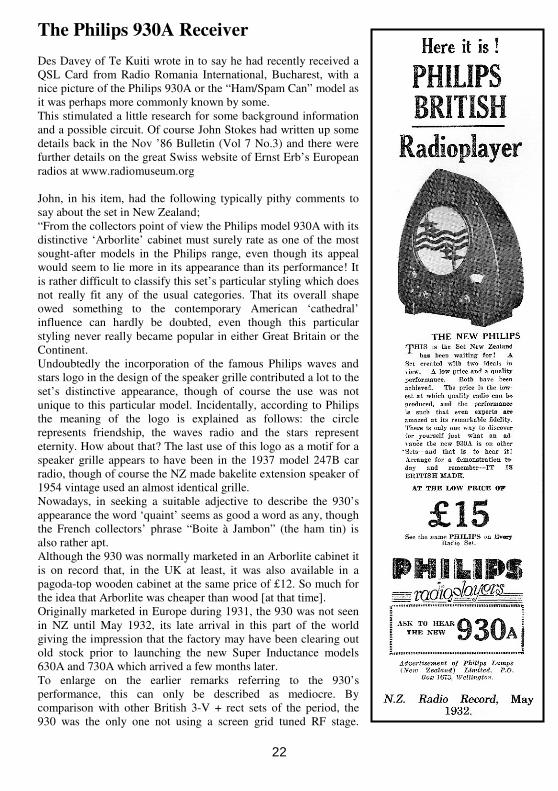
The Philips 930A Receiver
Des Davey of Te Kuiti wrote in to say he had recently received a
QSL Card from Radio Romania International, Bucharest, with a
nice picture of the Philips 930A or the “Ham/Spam Can” model as
it was perhaps more commonly known by some.
This stimulated a little research for some background information
and a possible circuit. Of course John Stokes had written up some
details back in the Nov ’86 Bulletin (Vol 7 No.3) and there were
further details on the great Swiss website of Ernst Erb’s European
radios at www.radiomuseum.org
John, in his item, had the following typically pithy comments to
say about the set in New Zealand;
“From the collectors point of view the Philips model 930A with its
distinctive ‘Arborlite’ cabinet must surely rate as one of the most
sought-after models in the Philips range, even though its appeal
would seem to lie more in its appearance than its performance! It
is rather difficult to classify this set’s particular styling which does
not really fit any of the usual categories. That its overall shape
owed something to the contemporary American ‘cathedral’
influence can hardly be doubted, even though this particular
styling never really became popular in either Great Britain or the
Continent.
Undoubtedly the incorporation of the famous Philips waves and
stars logo in the design of the speaker grille contributed a lot to the
set’s distinctive appearance, though of course the use was not
unique to this particular model. Incidentally, according to Philips
the meaning of the logo is explained as follows: the circle
represents friendship, the waves radio and the stars represent
eternity. How about that? The last use of this logo as a motif for a
speaker grille appears to have been in the 1937 model 247B car
radio, though of course the NZ made bakelite extension speaker of
1954 vintage used an almost identical grille.
Nowadays, in seeking a suitable adjective to describe the 930’s
appearance the word ‘quaint’ seems as good a word as any, though
the French collectors’ phrase “Boite à Jambon” (the ham tin) is
also rather apt.
Although the 930 was normally marketed in an Arborlite cabinet it
is on record that, in the UK at least, it was also available in a
pagoda-top wooden cabinet at the same price of £12. So much for
the idea that Arborlite was cheaper than wood [at that time].
Originally marketed in Europe during 1931, the 930 was not seen
in NZ until May 1932, its late arrival in this part of the world
giving the impression that the factory may have been clearing out
old stock prior to launching the new Super Inductance models
630A and 730A which arrived a few months later.
To enlarge on the earlier remarks referring to the 930’s
performance, this can only be described as mediocre. By
comparison with other British 3-V + rect sets of the period, the
930 was the only one not using a screen grid tuned RF stage.
22
Furthermore its single tuning condenser was one of the solid dielectric type and the long outmoded
rotating tickler system of regeneration was used. Altogether a most unprogressive design, difficult to
account for as Philips were marketing other models at the same time, such as the 2514, which used a
stage of tuned SG amplification ahead of the detector.
An unusual feature of the 930 was the use of a two-stage resistance-capacitance coupled audio
section ahead of the B443 (PM24) output pentode, causing the set to be described as having “large
LF amplification”. Large LF amplification it may have but it was a different story when it came to
the front end. Here, lack of selectivity, consequent upon the use of only one tuned circuit, was the
set’s main weakness.
Because of this it might have been expected that when Philips brought out the 5-valve model – the
932A – using the same chassis and cabinet, that this aspect of the set’s performance would have
been improved upon. Not so! Although now using a screen-grid valve ahead of the detector, the
stage itself was untuned and so contributed virtually nothing to improve selectivity. Admittedly, it
would have been impossible to find room for a two-ganged tuning capacitor and the extra coil
needed, to say nothing of the band-switching complication on the existing chassis, but one gets the
feeling that the addition of the screen-grid valve served little purpose other than to allow the set to
be advertised as a ‘screen-grid model’.
Here in NZ both models were being advertised side by side in 1932, the 930 at £15 and the 932 at
£29-10. Bearing in mind that the SG RF stage of the latter was very much in the nature of a
makeshift addition, the enormous difference in the prices is hard to reconcile. Rather obviously the
earlier model was being sold at under its true price in order to clear out existing stocks.”
Ernst Erb’s site has more comment and there is a forum discussion about the set design and the
differing types of base; the wooden and moulded Bakelite factory made variations.
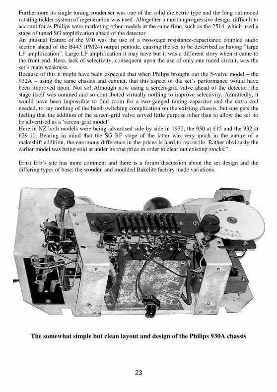
The somewhat simple but clean layout and design of the Philips 930A chassis
23
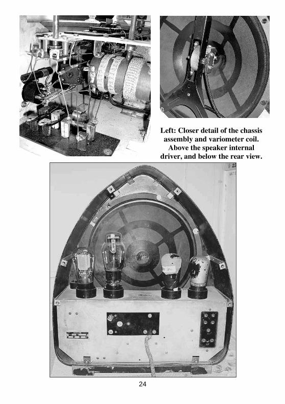
Left: Closer detail of the chassis
assembly and variometer coil.
Above the speaker internal
driver, and below the rear view.
24
25
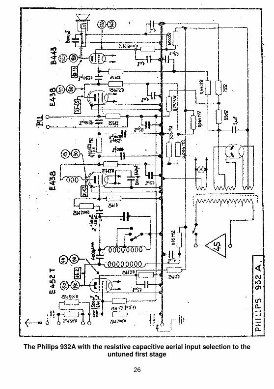
The Philips 932A with the resistive capacitive aerial input selection to the untuned first stage
26
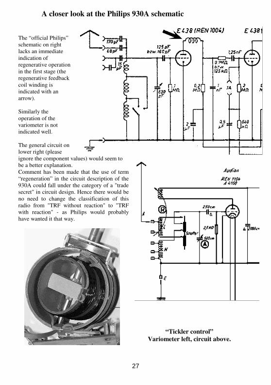
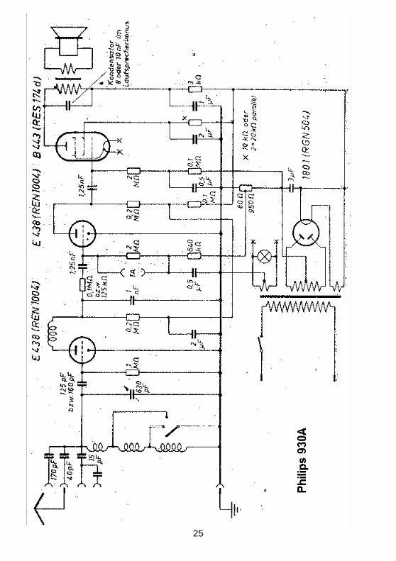
A closer look at the Philips 930A schematic
The “official Philips”
schematic on right
lacks an immediate
indication of
regenerative operation
in the first stage (the
regenerative feedback
coil winding is
indicated with an
arrow).
Similarly the
operation of the
variometer is not
indicated well.
The general circuit on
lower right (please
ignore the component values) would seem to
be a better explanation.
Comment has been made that the use of term
“regeneration” in the circuit description of the
930A could fall under the category of a "trade
secret" in circuit design. Hence there would be
no need to change the classification of this
radio from "TRF without reaction" to "TRF
with reaction" - as Philips would probably
have wanted it that way.
“Tickler control”
Variometer left, circuit above.
27
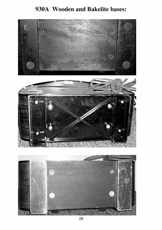
930A Wooden and Bakelite bases:
28
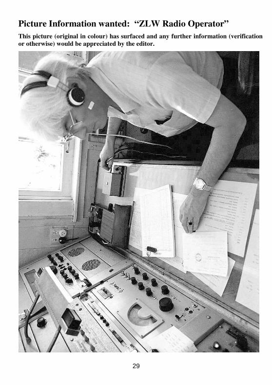
Picture Information wanted: “ZLW Radio Operator”
This picture (original in colour) has surfaced and any further information (verification
or otherwise) would be appreciated by the editor.
29
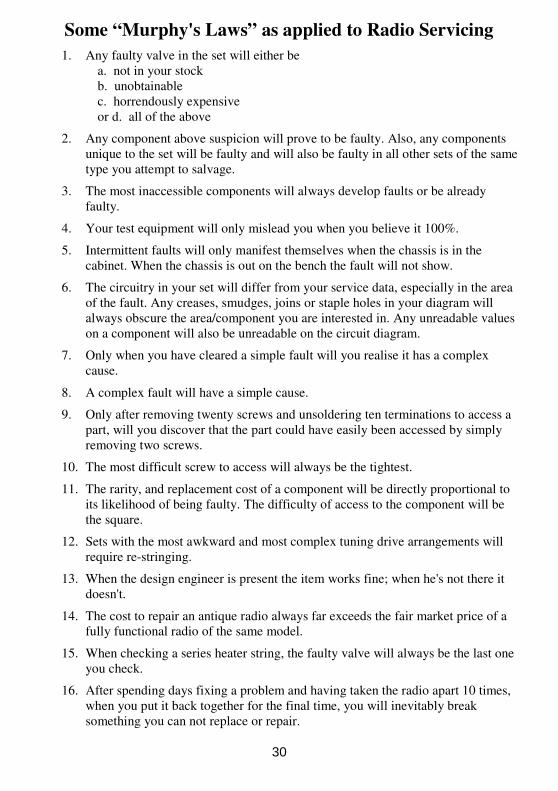
Some “Murphy's Laws” as applied to Radio Servicing
1. Any faulty valve in the set will either be
a. not in your stock
b. unobtainable
c. horrendously expensive
or d. all of the above
2. Any component above suspicion will prove to be faulty. Also, any components
unique to the set will be faulty and will also be faulty in all other sets of the same
type you attempt to salvage.
3. The most inaccessible components will always develop faults or be already
faulty.
4. Your test equipment will only mislead you when you believe it 100%.
5. Intermittent faults will only manifest themselves when the chassis is in the
cabinet. When the chassis is out on the bench the fault will not show.
6. The circuitry in your set will differ from your service data, especially in the area
of the fault. Any creases, smudges, joins or staple holes in your diagram will
always obscure the area/component you are interested in. Any unreadable values
on a component will also be unreadable on the circuit diagram.
7. Only when you have cleared a simple fault will you realise it has a complex
cause.
8. A complex fault will have a simple cause.
9. Only after removing twenty screws and unsoldering ten terminations to access a
part, will you discover that the part could have easily been accessed by simply
removing two screws.
10. The most difficult screw to access will always be the tightest.
11. The rarity, and replacement cost of a component will be directly proportional to
its likelihood of being faulty. The difficulty of access to the component will be
the square.
12. Sets with the most awkward and most complex tuning drive arrangements will
require re-stringing.
13. When the design engineer is present the item works fine; when he's not there it
doesn't.
14. The cost to repair an antique radio always far exceeds the fair market price of a
fully functional radio of the same model.
15. When checking a series heater string, the faulty valve will always be the last one
you check.
16. After spending days fixing a problem and having taken the radio apart 10 times,
when you put it back together for the final time, you will inevitably break
something you can not replace or repair.
30
MARKETPLACE Advertisements for the next bulletin should reach the editor by the 15th of the prior month. These must be neatly hand printed, typed or printed on a separate page, posted to the NZVRS (for details see page 2) or emailed to
[email protected] Please - no verbal or
telephoned adverts, also don’t forget to include some contact details; eg postal, telephone & email if applicable. There is no charge for members’ adverts but please remember that the NZVRS is not responsible for any transactions between members.
AVAILABLE
Valve Cartons – plain white flat packs • Small & GT size $12 per 100 • Medium size $15 per 100 • Large size $25 per 100 Plus post and package per order. Contact: Paul Burt, 44 Hastings St West, Christchurch 8023. Tel: 03 - 960 7158, Mob: 021 0245 0084 Email: [email protected]
NZVRS CAPACITORS for sale to members only please order via Gerry Billman, 30A Rowan Rd. Epsom, Auckland 1023. Email: [email protected] Tel: 09 - 625 6568 Metal polyester film, axial leads, (µF): 0.01 630 Volts 50 cents each 0.022 630 Volts 50 cents each 0.033 630 Volts 50 cents each 0.05 630 Volts 50 cents each 0.1 630 Volts 50 cents each 0.22 630 Volts 50 cents each 0.33 630 Volts 50 cents each 1uF 400 Volts $1.00 each Electrolytic capacitors, polarized, axial 10µF 450 Volts $1.50 each 20µF 450 Volts $2.00 each 40µF 450 Volts $3.00 each 47uF 450 Volts $3.50 each 100µF 450 Volts $5.00 each Lamps 6.3 volts 150 mA (low wattage) MES & Bayonet 50c each Please add $3.50 per order for post & package or contact Gerry direct for a postage quote. All
cheques to be made out to the ‘NZVRS’ (and crossed "Not Transferable") please.
For Sale
1 x Pye mantel all wave PZ92, 6 valve radio. Price $70. no viewing except by previous phone appointment or shipping. 1 x Pye Bakelite all wave bands 5 valve Cambridge model, these models are excellent for shortwave reception, bandwidth. Price $75. Contact: Mike Edwards 47 Martyn St. Waiuku 2123. Ex army Mk II ZC1. Has been used as a receiver only for short wave reception. Please contact Des Davey by letter for further details. Des Davey, 16 View Road, Te Kuiti 3910.
WANTED
I was wondering if I could place an advert on behalf of the Ferrymead Aircraft museum restoration group? Sure! The Ferrymead Aircraft Museum restoration group need both a Bendix TA-2J and Marconi T1154 transmitters for their aircraft which I am happy to restore if these can be found, Unfortunately, I do not have a spare T1154 for them myself - mine is already spoken for - so I would like to obtain each of these in re-storable condition if possible. Thank you. Best regards, Ian Thompson (Christchurch) <[email protected]> Wanted to buy a ground plane CB antenna in good working order for my CB set. Contact Des Davey, 16 View Road, Te Kuiti 3910 Wanting an ARC-5 239 kHz 3rd IF
Transformer (7269). Also, a T-17 microphone as used with 48 transmitters, or a PL-68 plug as used with these microphones. Contact: Bill Cousins, 20 Buick Street, Blenheim 7201 Tel: 03-579 3121 Email: [email protected] Wanted, a Hallicrafters SX-28 receiver. Contact Jeff King Tel: 03-332 5446 (evenings), or email: [email protected]
31
I'm trying to find the following bits to finish off a couple of projects:
• 2 x 6CY7 for a "Rock-Ola" chassis, proving hard to find as they were usually only used in the U.S.
• 1 x ECC803S Twin Triode.
• An EL37 tube to replace a failed one and make a pair for a PP output stage.
• An output transformer for a Leak TL12 plus, or a chassis, mine is arcing and I don't know anyone that re-winds these now.
Any help appreciated, Regards, Dave Kemp. Tel: 09- 376 2475 or Mob: 027 724 7244 1/26 Aliford Ave, One Tree Hill, Auckland Email: [email protected] Wanted: chassis and speaker for COMPANION, JOHNS LTD, MODEL 55BC, BY WELLMAYDE. Contact Al Watson, 30 Newman Ave, Brightwater, Nelson, ph 03- 542 3733, email: [email protected] Wanted: Brass Escutcheon for Philco 70 F4 Speaker for Atwater Kent model 60 Gareth Cawood Phone 09- 626 6587 "Gareth Cawood" <[email protected]>
Past Sales or Auctions The Society wishes to thank Steve Kenyon for a recent generous donation of books and components to the Society. These belonged to Ward Kenyon, Steve’s late Father who worked for the railways and lived in Huntly. Ward had an interest in electronics and enjoyed, studying course notes and building little battery powered projects as a hobby. His projects were well constructed and often cleverly housed in recycled cases and boxes. Over the years he had accumulated many tools and components to aid with his hobby. At the last NZVRS meeting the books and components were included in the donated items for the members’ auction. The sum of $94 was raised for the club, and the gear now has keen new owners. Also at the last auction night the sum of $127 was raised from goods donated by John Pettit and Basil Padgett
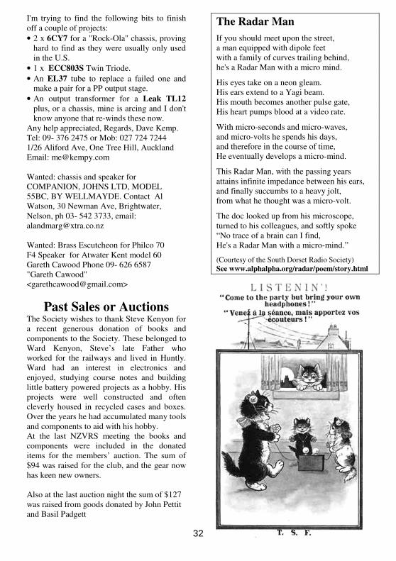
The Radar Man
If you should meet upon the street, a man equipped with dipole feet with a family of curves trailing behind, he's a Radar Man with a micro mind.
His eyes take on a neon gleam. His ears extend to a Yagi beam. His mouth becomes another pulse gate, His heart pumps blood at a video rate.
With micro-seconds and micro-waves, and micro-volts he spends his days, and therefore in the course of time, He eventually develops a micro-mind.
This Radar Man, with the passing years attains infinite impedance between his ears, and finally succumbs to a heavy jolt, from what he thought was a micro-volt.
The doc looked up from his microscope, turned to his colleagues, and softly spoke “No trace of a brain can I find, He's a Radar Man with a micro-mind.”
(Courtesy of the South Dorset Radio Society) See www.alphalpha.org/radar/poem/story.html
32