Embed Size (px)
Citation preview

This ISM device complies with Canadian ICES-001.Cet appareil ISM est conforme à la norme NMB-001 Canada.Nellcor Puritan Bennett Inc. is an affiliate of Tyco Healthcare. Nellcor, Oxiband, Durasensor, OxiCliq, OxiBand, Dura-Y, MAX-FAST, SatSeconds, PediCheck, Oxismart and OXIMAX are trademarks of Nellcor Puritan Bennett Inc.To obtain information about a warranty, if any, contact Nellcor’s Technical Services Department, or your local representative.Purchase of this instrument confers no express or implied license under any Nellcor Puritan Bennett patent to use the instrument with any sensor that is not manufactured or licensed by Nellcor Puritan Bennett.Covered by one or more of the following U.S. Patents and foreign equivalents: 4,621,643; 4,653,498; 4,700,708; 4,770,179; Re. 35,122; 4,802,486; 4,869,254; 4,928,692; 4,934,372; 5,078,136; 5,351,685; 5,368,026; 5,485,847; 5,533,507; 5,662,106; 5,853,364, and 6,083,172.
C o n t e n t s
Contents . . . . . . . . . . . . . . . . . . . . . . . . . . . . . . . . . . . . . . . . . . . . . . . . . . . . . iFigures . . . . . . . . . . . . . . . . . . . . . . . . . . . . . . . . . . . . . . . . . . . . . . . . . . . . . vTables . . . . . . . . . . . . . . . . . . . . . . . . . . . . . . . . . . . . . . . . . . . . . . . . . . . . . .viSafety Information . . . . . . . . . . . . . . . . . . . . . . . . . . . . . . . . . . . . . . . . . . . . 1
Warnings .................................................................................1Cautions ..................................................................................2Notes .......................................................................................3
Introduction . . . . . . . . . . . . . . . . . . . . . . . . . . . . . . . . . . . . . . . . . . . . . . . . . 5Intended Use for the N-550 .....................................................5
Description of Controls, Indicators, and Symbols . . . . . . . . . . . . . . . . . . 7Identification of Front Panel Buttons and Symbols ..................7Identification of Rear Panel Components ................................8N-550 Symbols ........................................................................8Description of Controls ............................................................9Description of Displays and Indicators ..................................11Description of Audible Indicators ...........................................13
Setting up the N-550 . . . . . . . . . . . . . . . . . . . . . . . . . . . . . . . . . . . . . . . . . . 15List of Components ...............................................................16Connecting the N-550 to AC Power ......................................17Connecting a Sensor to the N-550 ........................................17
Battery Operation . . . . . . . . . . . . . . . . . . . . . . . . . . . . . . . . . . . . . . . . . . . . 19Operating the N-550 on Battery Power .................................19
N-550 i
Low Battery Indicator .............................................................20Using the N-550 . . . . . . . . . . . . . . . . . . . . . . . . . . . . . . . . . . . . . . . . . . . . . 21
Turning on the N-550 ............................................................21Discussion ....................................................................21Procedure ....................................................................21Sensor Attached ..........................................................24No Sensor Attached .....................................................26
Sensor Message ...................................................................26
Contents
Setting the Pulse Beep Volume ............................................ 27Setting the Alarm Volume ..................................................... 28Setting Alarm Silence Duration ............................................. 28
Discussion ................................................................... 28Procedure .................................................................... 29
Disabling Audible Alarms ...................................................... 30Discussion ................................................................... 30Procedure .................................................................... 30
Verify Patient Settings ........................................................... 31Alarm Limits Changed Indicator ............................................ 33Setting Alarm Limits .............................................................. 34
Discussion ................................................................... 34Procedure .................................................................... 34
Setting SatSeconds Duration ................................................ 36Discussion ................................................................... 36Procedure .................................................................... 36
Setting the Data Port Baud Rate ........................................... 37Discussion ................................................................... 37Procedure .................................................................... 37
Setting the Data Port Protocol .............................................. 39Clearing Trend Information ................................................... 40
N-550 Trend . . . . . . . . . . . . . . . . . . . . . . . . . . . . . . . . . . . . . . . . . . . . . . . . .43Trend Data Operation ........................................................... 43Trend Data ............................................................................ 43
#1: Trend Print ............................................................. 44#2: Trend Clear ............................................................ 44#3: Not Used ................................................................ 44
ii
#4: Baud Rate .............................................................. 44#5: Data Port Printout .................................................. 45
Option 1 .............................................................. 45Option 2 .............................................................. 45
Using the Data Port . . . . . . . . . . . . . . . . . . . . . . . . . . . . . . . . . . . . . . . . . . .47Overview ............................................................................... 47Connecting to the Data Port .................................................. 47Data Port Pinouts .................................................................. 48
Contents
Data Port Setup .....................................................................49Discussion ....................................................................49Procedure ....................................................................50
Nurse Call Interface ...............................................................53Setting Nurse Call RS-232 Polarity ..............................54Setting Nurse Call Relays Normally Open/Closed .......54
Printing . . . . . . . . . . . . . . . . . . . . . . . . . . . . . . . . . . . . . . . . . . . . . . . . . . . . 57Printing N-550 Real-Time Data .............................................57Trend Data Printout ...............................................................59
Column Headings ........................................................60Data Source .................................................................61Device/Software Revision Level ..................................61Alarm Limits .................................................................61N-550 Mode .................................................................62Data Column Headings ................................................62Time .............................................................................62Patient Data .................................................................63Operating Status ..........................................................63
Sensors and Accessories . . . . . . . . . . . . . . . . . . . . . . . . . . . . . . . . . . . . . 65Selecting a Sensor ................................................................65Biocompatibility Testing .........................................................68Optional Accessories .............................................................68
Foot Switch ..................................................................69Visual Alarm Indicator ..................................................69Pole Mount Bracket ......................................................70
Performance Considerations . . . . . . . . . . . . . . . . . . . . . . . . . . . . . . . . . . 71
N-550 iii
Performance Verification .......................................................71N-550 Performance Considerations ......................................71
Dysfunctional Hemoglobins .........................................72Anemia .........................................................................72Saturation .....................................................................72Pulse rates ...................................................................72
Sensor Performance Considerations ....................................72
Contents
Operator’s Menu . . . . . . . . . . . . . . . . . . . . . . . . . . . . . . . . . . . . . . . . . . . . .75Troubleshooting . . . . . . . . . . . . . . . . . . . . . . . . . . . . . . . . . . . . . . . . . . . . .77
Error Codes ........................................................................... 77Corrective Action ................................................................... 78EMI (Electro-magnetic Interference) ..................................... 81Obtaining Technical Assistance ............................................ 82
Maintenance . . . . . . . . . . . . . . . . . . . . . . . . . . . . . . . . . . . . . . . . . . . . . . . . .85Returning the N-550 .............................................................. 85Service .................................................................................. 85Periodic Safety Checks ......................................................... 86Cleaning ................................................................................ 86
Technical Information . . . . . . . . . . . . . . . . . . . . . . . . . . . . . . . . . . . . . . . . .87Description of Alarms ............................................................ 87Factory Defaults .................................................................... 88SatSeconds Display .............................................................. 89Describing SatSeconds ......................................................... 90SatSeconds “Safety Net” ...................................................... 92
Principles of Operation . . . . . . . . . . . . . . . . . . . . . . . . . . . . . . . . . . . . . . . .93Oximetry Overview ................................................................ 93Automatic Calibration ............................................................ 94Functional versus Fractional Saturation ................................ 95Measured versus Calculated Saturation ............................... 95
Specifications . . . . . . . . . . . . . . . . . . . . . . . . . . . . . . . . . . . . . . . . . . . . . . .97Performance ......................................................................... 97Electrical ............................................................................. 101
iv
Environmental Conditions ................................................... 102Physical Characteristics ...................................................... 104Compliance ......................................................................... 105
Index . . . . . . . . . . . . . . . . . . . . . . . . . . . . . . . . . . . . . . . . . . . . . . . . . . . . . .109
Contents
N-550 v
F i g u r e s
Figure 1: Front Panel Buttons and Symbols .........................7Figure 2: Rear Panel Symbols ..............................................8Figure 3: Data Port Pin Layout ...........................................49Figure 4: Real-Time Data Printout ......................................59Figure 5: Trend Data Printout .............................................60Figure 6: Alarm Response with SatSeconds ......................91Figure 7: Oxyhemoglobin Dissociation Curve ....................96
Contents
vi
Ta b l e s
Table 1: Data Port Pinouts .................................................. 48Table 2: Nellcor Oximetry Sensor Models
and Patient Weights ......................................... 66Table 3: Operator’s Menu ................................................... 75Table 4: Error Codes ........................................................... 78Table 5: Factory Default Settings ........................................ 88Table 6: Tone Definition ...................................................... 98
S a f e t y I n f o r m a t i o n
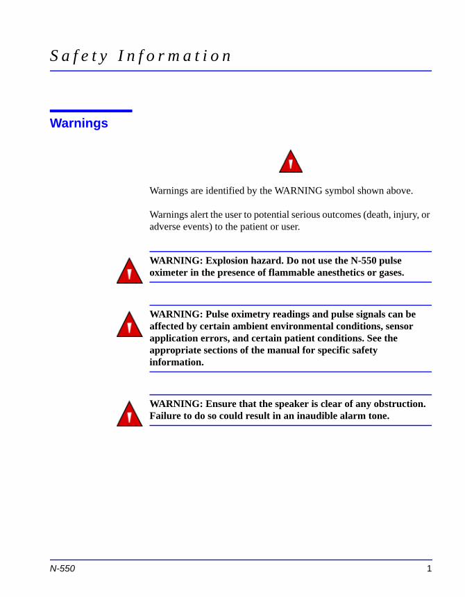
Warnings
Warnings are identified by the WARNING symbol shown above.
Warnings alert the user to potential serious outcomes (death, injury, or adverse events) to the patient or user.
WARNING: Explosion hazard. Do not use the N-550 pulse oximeter in the presence of flammable anesthetics or gases.
WARNING: Pulse oximetry readings and pulse signals can be affected by certain ambient environmental conditions, sensor application errors, and certain patient conditions. See the appropriate sections of the manual for specific safety information.
WARNING: Ensure that the speaker is clear of any obstruction. Failure to do so could result in an inaudible alarm tone.
N-550 1
Safety Information
Cautions
Cautions are identified by the CAUTION symbol shown above.
Cautions alert the user to exercise care necessary for the safe and effective use of the N-550.
CAUTION: When connecting the N-550 to any instrument, verify proper operation before clinical use. Both the N-550 and the instrument connected to it must be connected to a grounded outlet. Accessory equipment connected to the N-550's data interface must be certified according to IEC Standard 60950 for data-processing equipment or IEC Standard 60601-1 for electromedical equipment. All combinations of equipment must be in compliance with IEC Standard 60601-1-1 systems requirements. Anyone who connects additional equipment to the signal input port or signal output port (N-550 data port connector) configures a medical system and is therefore responsible for ensuring that the system complies with the requirements of system standard IEC Standard 60601-1-1 and the electromagnetic compatibility system standard IEC Standard 60601-1-2. The N-550 accuracy may degrade if it is connected to secondary I/O devices when the instrument is not connected to earth reference.
CAUTION: Do not lift the N-550 by the sensor cable or power
2
cord because the cable or cord could disconnect from the N-550, causing damage to the N-550 or injuring the patient.
CAUTION: Federal law (U.S.A.) restricts this device to sale by or on the order of a physician.
Safety Information
Notes
Notes are identified by the Note symbol shown above.
Notes provide additional useful information.
N-550 3

Blank Page
I n t r o d u c t i o n
WARNING: The N-550 is intended only as an adjunct in patient assessment. It must be used in conjunction with clinical signs and symptoms. Do not make any clinical judgments based on the oximeter's measurements only.
Intended Use for the N-550
The N-550 Pulse Oximeter is indicated for the continuous noninvasive monitoring of functional oxygen saturation of arterial hemoglobin (SpO2) and pulse rate. The N-550 is intended for use with neonatal, pediatric, and adult patients during both no-motion and motion conditions and for patients who are well or poorly perfused, in hospitals, hospital-type facilities, intra-hospital transport, and home environments. For prescription use only.
Note: Hospital use typically covers such areas as general care floors, operating rooms, special procedure areas, intensive and critical care areas, within the hospital plus hospital-type facilities. Hospital-type facilities include physician office-based facilities, sleep labs, skilled nursing facilities, surgicenters, and sub-acute centers.
Intra-hospital transport includes transport of a patient within
N-550 5
the hospital or hospital-type facility.
Use with any particular patient requires the selection of an appropriate oxygen transducer (sensor) as described in this Operator's Manual.
Motion performance claims are applicable to models MAX-A, MAX-AL, MAX-P, MAX-N, and MAX-I Nellcor OXIMAXTM oximetry sensors.

Blank Page
D e s c r i p t i o n o f C o n t r o l s , I n d i c a t o r s , a n d S y m b o l s
Identification of Front Panel Buttons and Symbols
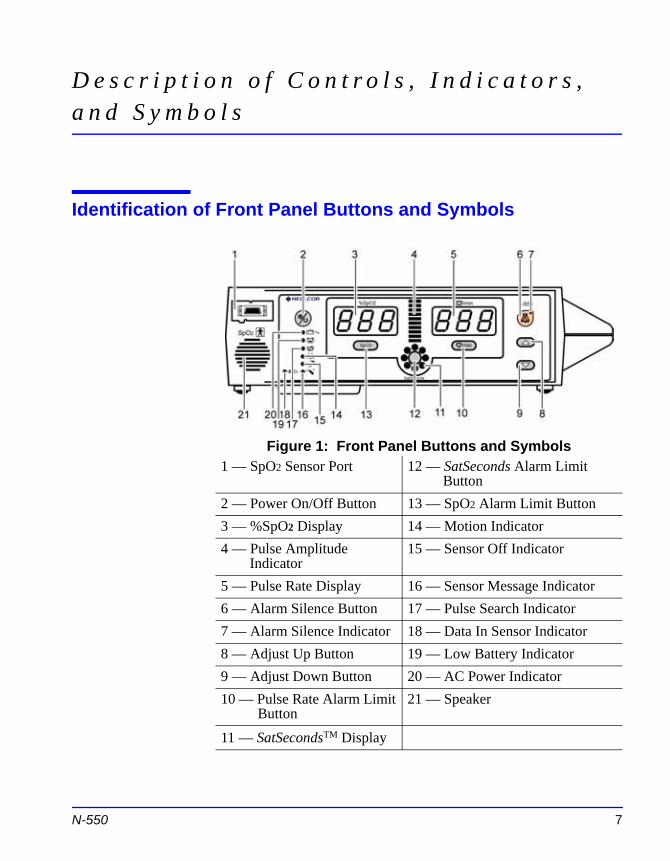
Figure 1: Front Panel Buttons and Symbols1 — SpO2 Sensor Port 12 — SatSeconds Alarm Limit
Button2 — Power On/Off Button 13 — SpO2 Alarm Limit Button3 — %SpO2 Display 14 — Motion Indicator4 — Pulse Amplitude
Indicator15 — Sensor Off Indicator
5 — Pulse Rate Display 16 — Sensor Message Indicator
N-550 7
6 — Alarm Silence Button 17 — Pulse Search Indicator7 — Alarm Silence Indicator 18 — Data In Sensor Indicator8 — Adjust Up Button 19 — Low Battery Indicator9 — Adjust Down Button 20 — AC Power Indicator10 — Pulse Rate Alarm Limit
Button21 — Speaker
11 — SatSecondsTM Display
Description of Controls, Indicators, and Symbols
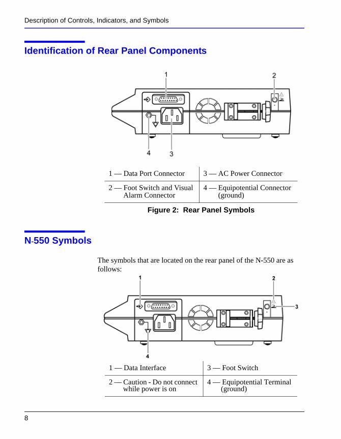
Identification of Rear Panel Components
Figure 2: Rear Panel Symbols
N-550 Symbols
The symbols that are located on the rear panel of the N-550 are as follows:
1 — Data Port Connector 3 — AC Power Connector
2 — Foot Switch and Visual Alarm Connector
4 — Equipotential Connector (ground)
8
1 — Data Interface 3 — Foot Switch
2 — Caution - Do not connect while power is on
4 — Equipotential Terminal (ground)
Description of Controls, Indicators, and Symbols
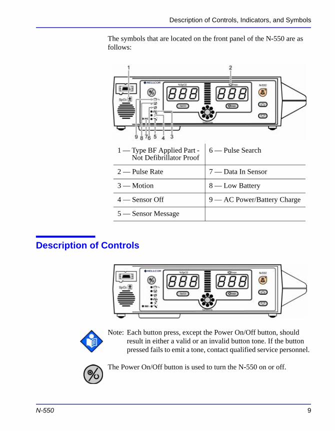
The symbols that are located on the front panel of the N-550 are as follows:
Description of Controls
1 — Type BF Applied Part - Not Defibrillator Proof
6 — Pulse Search
2 — Pulse Rate 7 — Data In Sensor
3 — Motion 8 — Low Battery
4 — Sensor Off 9 — AC Power/Battery Charge
5 — Sensor Message
N-550 9
Note: Each button press, except the Power On/Off button, should result in either a valid or an invalid button tone. If the button pressed fails to emit a tone, contact qualified service personnel.
The Power On/Off button is used to turn the N-550 on or off.
Description of Controls, Indicators, and Symbols
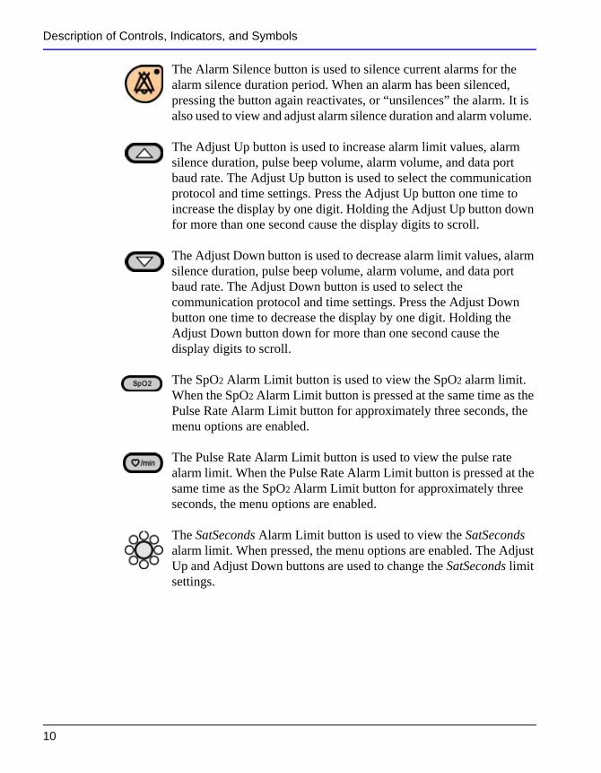
The Alarm Silence button is used to silence current alarms for the alarm silence duration period. When an alarm has been silenced, pressing the button again reactivates, or “unsilences” the alarm. It is also used to view and adjust alarm silence duration and alarm volume.
The Adjust Up button is used to increase alarm limit values, alarm silence duration, pulse beep volume, alarm volume, and data port baud rate. The Adjust Up button is used to select the communication protocol and time settings. Press the Adjust Up button one time to increase the display by one digit. Holding the Adjust Up button down for more than one second cause the display digits to scroll.
The Adjust Down button is used to decrease alarm limit values, alarm silence duration, pulse beep volume, alarm volume, and data port baud rate. The Adjust Down button is used to select the communication protocol and time settings. Press the Adjust Down button one time to decrease the display by one digit. Holding the Adjust Down button down for more than one second cause the display digits to scroll.
The SpO2 Alarm Limit button is used to view the SpO2 alarm limit. When the SpO2 Alarm Limit button is pressed at the same time as the Pulse Rate Alarm Limit button for approximately three seconds, the menu options are enabled.
The Pulse Rate Alarm Limit button is used to view the pulse rate alarm limit. When the Pulse Rate Alarm Limit button is pressed at the same time as the SpO2 Alarm Limit button for approximately three seconds, the menu options are enabled.
The SatSeconds Alarm Limit button is used to view the SatSeconds
10
alarm limit. When pressed, the menu options are enabled. The Adjust Up and Adjust Down buttons are used to change the SatSeconds limit settings.
Description of Controls, Indicators, and Symbols
Description of Displays and Indicators
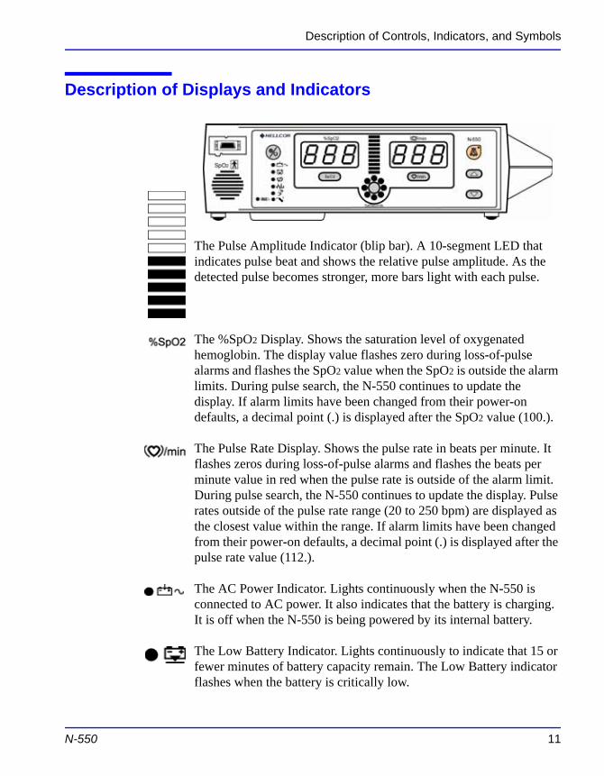
The Pulse Amplitude Indicator (blip bar). A 10-segment LED that indicates pulse beat and shows the relative pulse amplitude. As the detected pulse becomes stronger, more bars light with each pulse.
The %SpO2 Display. Shows the saturation level of oxygenated hemoglobin. The display value flashes zero during loss-of-pulse alarms and flashes the SpO2 value when the SpO2 is outside the alarm limits. During pulse search, the N-550 continues to update the display. If alarm limits have been changed from their power-on defaults, a decimal point (.) is displayed after the SpO2 value (100.).
The Pulse Rate Display. Shows the pulse rate in beats per minute. It flashes zeros during loss-of-pulse alarms and flashes the beats per minute value in red when the pulse rate is outside of the alarm limit. During pulse search, the N-550 continues to update the display. Pulse rates outside of the pulse rate range (20 to 250 bpm) are displayed as the closest value within the range. If alarm limits have been changed from their power-on defaults, a decimal point (.) is displayed after the
N-550 11
pulse rate value (112.).
The AC Power Indicator. Lights continuously when the N-550 is connected to AC power. It also indicates that the battery is charging. It is off when the N-550 is being powered by its internal battery.
The Low Battery Indicator. Lights continuously to indicate that 15 or fewer minutes of battery capacity remain. The Low Battery indicator flashes when the battery is critically low.
Description of Controls, Indicators, and Symbols
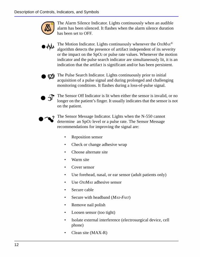
The Alarm Silence Indicator. Lights continuously when an audible alarm has been silenced. It flashes when the alarm silence duration has been set to OFF.
The Motion Indicator. Lights continuously whenever the OXIMAX® algorithm detects the presence of artifact independent of its severity or the impact on the SpO2 or pulse rate values. Whenever the motion indicator and the pulse search indicator are simultaneously lit, it is an indication that the artifact is significant and/or has been persistent.
The Pulse Search Indicator. Lights continuously prior to initial acquisition of a pulse signal and during prolonged and challenging monitoring conditions. It flashes during a loss-of-pulse signal.
The Sensor Off Indicator is lit when either the sensor is invalid, or no longer on the patient’s finger. It usually indicates that the sensor is not on the patient.
The Sensor Message Indicator. Lights when the N-550 cannot determine an SpO2 level or a pulse rate. The Sensor Message recommendations for improving the signal are:
• Reposition sensor
• Check or change adhesive wrap
• Choose alternate site
• Warm site
• Cover sensor
• Use forehead, nasal, or ear sensor (adult patients only)
12
• Use OXIMAX adhesive sensor
• Secure cable
• Secure with headband (MAX-FAST)
• Remove nail polish
• Loosen sensor (too tight)
• Isolate external interference (electrosurgical device, cell phone)
• Clean site (MAX-R)
Description of Controls, Indicators, and Symbols
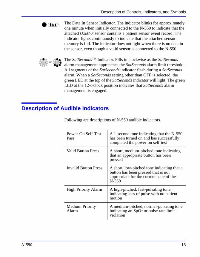
The Data In Sensor Indicator. The indicator blinks for approximately one minute when initially connected to the N-550 to indicate that the attached OXIMAX sensor contains a patient sensor event record. The indicator lights continuously to indicate that the attached sensor memory is full. The indicator does not light when there is no data in the sensor, even though a valid sensor is connected to the N-550.
The SatSecondsTM Indicator. Fills in clockwise as the SatSeconds alarm management approaches the SatSeconds alarm limit threshold. All segments of the SatSeconds indicator flash during a SatSeconds alarm. When a SatSeconds setting other than OFF is selected, the green LED at the top of the SatSeconds indicator will light. The green LED at the 12-o'clock position indicates that SatSeconds alarm management is engaged.
Description of Audible Indicators
Following are descriptions of N-550 audible indicators.
Power-On Self-Test Pass
A 1-second tone indicating that the N-550 has been turned on and has successfully completed the power-on self-test
Valid Button Press A short, medium-pitched tone indicating that an appropriate button has been pressed
Invalid Button Press A short, low-pitched tone indicating that a button has been pressed that is not appropriate for the current state of the
N-550 13
N-550
High Priority Alarm A high-pitched, fast-pulsating tone indicating loss of pulse with no patient motion
Medium Priority Alarm
A medium-pitched, normal-pulsating tone indicating an SpO2 or pulse rate limit violation
Description of Controls, Indicators, and Symbols
Low Priority Alarm A low-pitched, slow-pulsating tone indicating a sensor disconnect, low battery, or N-550 failure
Alarm Silence Reminder
Three beeps that sound approximately every 3 minutes when alarms are silenced with the alarm silence duration set to OFF
Pulse Beep A single beep sounds for each detected pulse. The pitch changes as monitored SpO2 values increase or decrease.
Volume Setting Tone A continuous tone that is used to adjust the alarm volume
Confirmation Tone Three beeps sound to indicate that default settings have been saved or reset to factory defaults or trend data has been deleted
14
S e t t i n g u p t h e N - 5 5 0
WARNING: Explosion hazard. Do not use the N-550 pulse oximeter in the presence of flammable anesthetics or gases.
WARNING: Pulse oximetry readings and pulse signals can be affected by certain ambient environmental conditions, sensor application errors, and certain patient conditions. See the appropriate sections of the manual for specific safety information.
WARNING: To ensure patient safety, do not place the N-550 in any position that might cause it to fall on the patient.
WARNING: As with all medical equipment, carefully route patient cabling to reduce the possibility of patient entanglement or strangulation.
WARNING: Disconnect the N-550 and Nellcor sensor from the patient during magnetic resonance imaging (MRI) scanning. Induced current could potentially cause burns. The N-550 may affect the MRI image; the MRI unit may affect the accuracy of
N-550 15
oximeter measurements.
WARNING: To ensure accurate performance and prevent device failure, do not subject the N-550 to extreme moisture, such as direct exposure to rain. Such exposure may cause inaccurate performance or device failure.
Setting up the N-550
WARNING: Do not use an N-550, sensor, cables, or connectors that appear to be damaged.
WARNING: The N-550 is not defibrillator-proof. However, it may remain attached to the patient during defibrillation or while an electrosurgical unit is in use, but the readings may be inaccurate during use and shortly thereafter.
WARNING: In the USA, do not connect the N-550 to an electrical outlet controlled by a wall switch because the N-550 may be accidentally turned off.
WARNING: Use only the DOC-10 pulse oximetry cable with the N-550. Use of another sensor cable will have an adverse effect on performance. Do not attach any cable that is intended for computer use to the sensor port. Do not connect any device other than a Nellcor-approved sensor to the sensor connector.
List of Components
1 — N-550 Pulse Oximeter
1 — Nellcor Sensor or Assortment Pack
16
1 — DOC-10 Pulse Oximeter Cable
1 — N-550 Operator's Manual
1 — Hospital-Grade Power Cord or power cord appropriate for country of sale
1 — Sensor Accuracy Grid
1 — Quick Guide
Setting up the N-550
Connecting the N-550 to AC Power
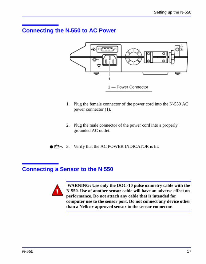
1. Plug the female connector of the power cord into the N-550 AC power connector (1).
2. Plug the male connector of the power cord into a properly grounded AC outlet.
3. Verify that the AC POWER INDICATOR is lit.
Connecting a Sensor to the N-550
WARNING: Use only the DOC-10 pulse oximetry cable with the
1 — Power Connector
N-550 17
N-550. Use of another sensor cable will have an adverse effect on performance. Do not attach any cable that is intended for computer use to the sensor port. Do not connect any device other than a Nellcor-approved sensor to the sensor connector.
Setting up the N-550
.
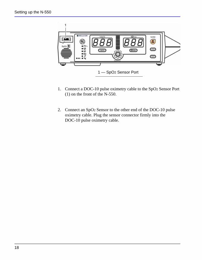
1. Connect a DOC-10 pulse oximetry cable to the SpO2 Sensor Port (1) on the front of the N-550.
2. Connect an SpO2 Sensor to the other end of the DOC-10 pulse oximetry cable. Plug the sensor connector firmly into the DOC-10 pulse oximetry cable.
1 — SpO2 Sensor Port
18
B a t t e r y O p e r a t i o n
WARNING: Dispose of an old battery by following local guidelines for disposal of lead acid batteries.
Operating the N-550 on Battery Power
The N-550 has an internal battery that may be used to power the N-550 during transport or when AC power is not available. A new, fully charged battery will provide at least 1.5 to 2 hours of monitoring time under the following conditions: no audible alarms sound and no serial output devices are attached.
Note: Whenever the N-550 is connected to AC power, the battery is being charged. Therefore, it is recommended that the N-550 remain connected to AC power when not in use. This will make a fully charged battery available for use at any time.
The N-550 cannot operate with a dead battery (even when plugged in). Before attempting to turn on an N-550 with a depleted battery, first plug the N-550 into an AC outlet to allow the battery to charge for a few minutes. The N-550 may then be powered on.
To charge a low or dead battery, connect the N-550 to AC power. A full charge of a dead battery takes 11 hours while the N-550 is turned
N-550 19
off or 12 hours while the N-550 is on.
When all of the following conditions are present for 15 minutes, the N-550 will automatically shut down:
• N-550 is running on battery power
• No buttons have been pressed
• No pulse has been detected (for example, when no patient is connected to the sensor or the sensor is disconnected)
Battery Operation
• No alarms are present (other than low battery or a non-correctable error)
Low Battery Indicator
The Low Battery Indicator lights and a low priority alarm begins to sound when 15 minutes but not more than 20 minutes of monitoring time remain on the existing battery charge. This alarm cannot be silenced while running on battery power. Connecting the N-550 to AC power will silence the alarm. If the N-550 is not connected to AC power within approximately 15 minutes, the N-550 will shut off.
Note: As the battery is used and recharged over a period of time, the amount of time between the onset of the low battery alarm and the N-550 shut-off may become shorter.
It is recommended that qualified service personnel replace the internal battery every 24 months.
CAUTION: If the N-550 is to be stored for 2 months or longer, notify service personnel to remove the battery from the N-550 prior to storage. Recharge the battery when it has not been charged for 2 or more months.
The Low Battery Indicator flashes and a high priority alarm begins to sound when the battery reaches the lowest battery voltage at which an N-550 can support normal operation. This alarm cannot be silenced while running on battery power. If the N-550 is not connected to AC power, the N-550 will shut off after 10 seconds.
20
U s i n g t h e N - 5 5 0
Turning on the N-550
Discussion
Before using the N-550 in a clinical setting, you must verify that the N-550 is working properly and is safe to use. Proper working condition can be verified by successful completion of the Power-On Self-Test (POST), described in the following section.
WARNING: The N-550 should not be used adjacent to or stacked with other equipment. If adjacent or stacked use is necessary, the N-550 should be observed to verify normal operation in the configuration in which it is used.
CAUTION: If any indicator or display element does not light, or the speaker does not sound, do not use the N-550. Instead, contact qualified service personnel, your local Nellcor representative, or Nellcor's Technical Services Department, 1.800.635.5267.
Note: The N-550 should complete the POST function within 12 seconds.
N-550 21
Procedure
1. Turn on the N-550 by pressing and holding the Power On/Off button for more than one second.
Using the N-550
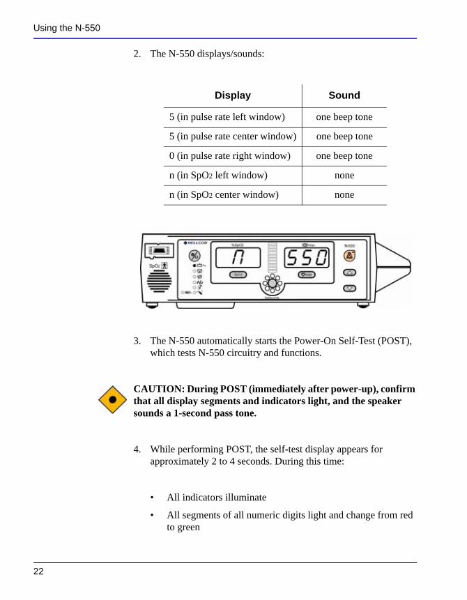
2. The N-550 displays/sounds:
3. The N-550 automatically starts the Power-On Self-Test (POST), which tests N-550 circuitry and functions.
CAUTION: During POST (immediately after power-up), confirm that all display segments and indicators light, and the speaker sounds a 1-second pass tone.
Display Sound
5 (in pulse rate left window) one beep tone
5 (in pulse rate center window) one beep tone
0 (in pulse rate right window) one beep tone
n (in SpO2 left window) none
n (in SpO2 center window) none
22
4. While performing POST, the self-test display appears for approximately 2 to 4 seconds. During this time:
• All indicators illuminate
• All segments of all numeric digits light and change from red to green
Using the N-550
• All segments of the Pulse Amplitude Display light
• All segments of the SatSeconds indicator light
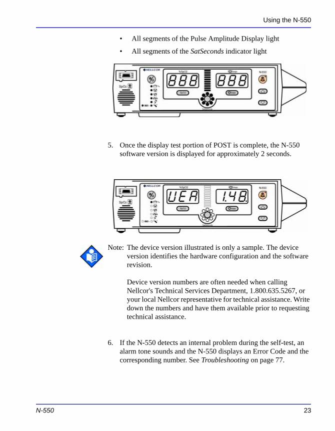
5. Once the display test portion of POST is complete, the N-550 software version is displayed for approximately 2 seconds.
Note: The device version illustrated is only a sample. The device version identifies the hardware configuration and the software revision.
Device version numbers are often needed when calling Nellcor's Technical Services Department, 1.800.635.5267, or your local Nellcor representative for technical assistance. Write
N-550 23
down the numbers and have them available prior to requesting technical assistance.
6. If the N-550 detects an internal problem during the self-test, an alarm tone sounds and the N-550 displays an Error Code and the corresponding number. See Troubleshooting on page 77.
Using the N-550
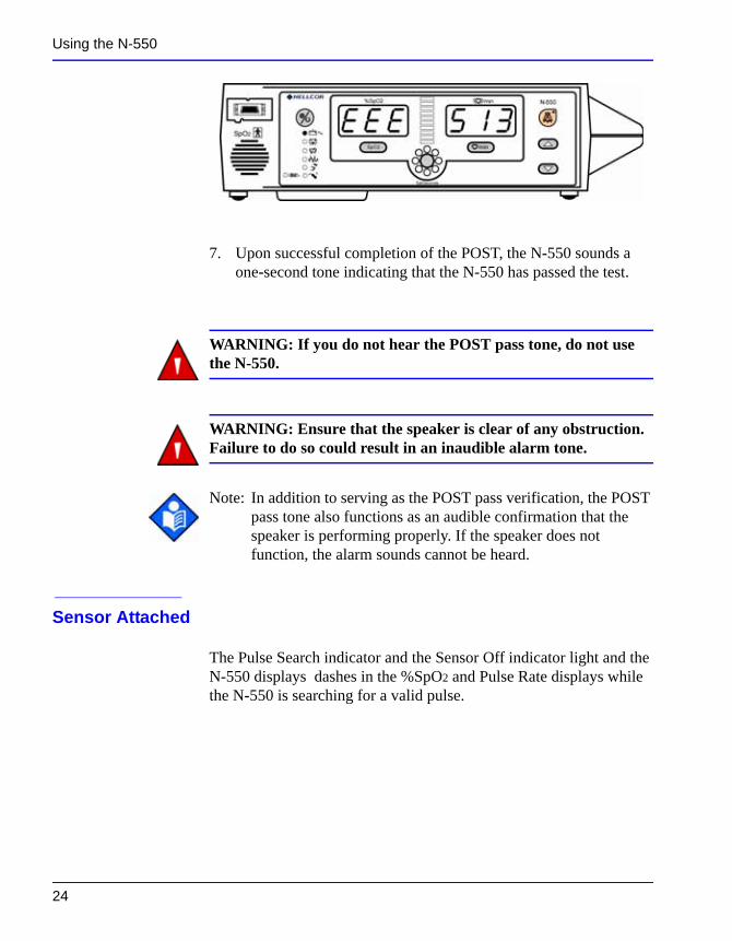
7. Upon successful completion of the POST, the N-550 sounds a one-second tone indicating that the N-550 has passed the test.
WARNING: If you do not hear the POST pass tone, do not use the N-550.
WARNING: Ensure that the speaker is clear of any obstruction. Failure to do so could result in an inaudible alarm tone.
Note: In addition to serving as the POST pass verification, the POST pass tone also functions as an audible confirmation that the speaker is performing properly. If the speaker does not function, the alarm sounds cannot be heard.
Sensor Attached
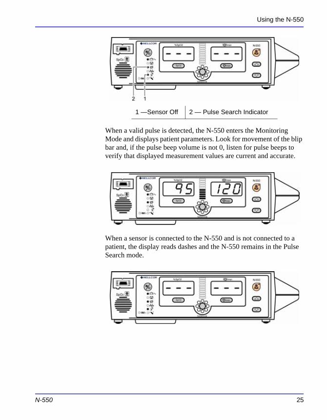
The Pulse Search indicator and the Sensor Off indicator light and the
24
N-550 displays dashes in the %SpO2 and Pulse Rate displays while the N-550 is searching for a valid pulse.
Using the N-550
When a valid pulse is detected, the N-550 enters the Monitoring Mode and displays patient parameters. Look for movement of the blip bar and, if the pulse beep volume is not 0, listen for pulse beeps to verify that displayed measurement values are current and accurate.
When a sensor is connected to the N-550 and is not connected to a patient, the display reads dashes and the N-550 remains in the Pulse Search mode.
1 —Sensor Off 2 — Pulse Search Indicator
N-550 25
Using the N-550
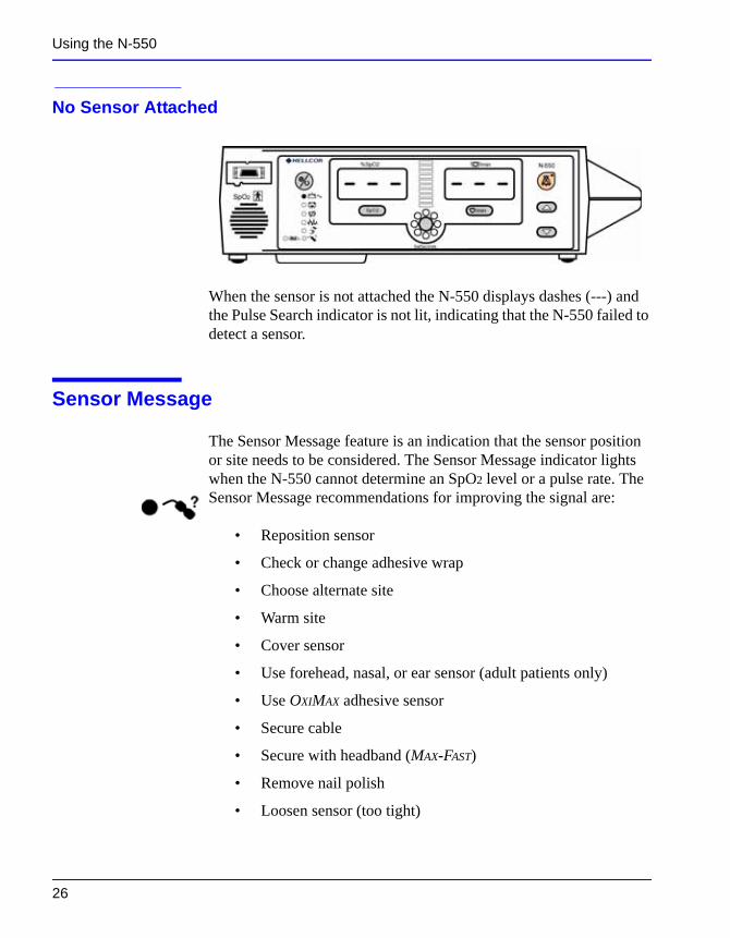
No Sensor Attached
When the sensor is not attached the N-550 displays dashes (---) and the Pulse Search indicator is not lit, indicating that the N-550 failed to detect a sensor.
Sensor Message
The Sensor Message feature is an indication that the sensor position or site needs to be considered. The Sensor Message indicator lights when the N-550 cannot determine an SpO2 level or a pulse rate. The Sensor Message recommendations for improving the signal are:
• Reposition sensor
• Check or change adhesive wrap
• Choose alternate site
• Warm site
• Cover sensor
26
• Use forehead, nasal, or ear sensor (adult patients only)
• Use OXIMAX adhesive sensor
• Secure cable
• Secure with headband (MAX-FAST)
• Remove nail polish
• Loosen sensor (too tight)
Using the N-550
• Isolate external interference (electrosurgical device, cell phone)
• Clean site (MAX-R)
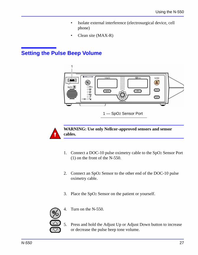
Setting the Pulse Beep Volume
WARNING: Use only Nellcor-approved sensors and sensor cables.
1. Connect a DOC-10 pulse oximetry cable to the SpO2 Sensor Port (1) on the front of the N-550.
2. Connect an SpO2 Sensor to the other end of the DOC-10 pulse oximetry cable.
1 — SpO2 Sensor Port
N-550 27
3. Place the SpO2 Sensor on the patient or yourself.
4. Turn on the N-550.
5. Press and hold the Adjust Up or Adjust Down button to increase or decrease the pulse beep tone volume.
Using the N-550
Setting the Alarm Volume
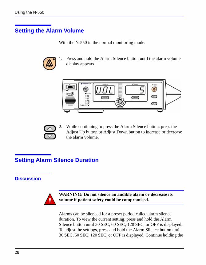
With the N-550 in the normal monitoring mode:
1. Press and hold the Alarm Silence button until the alarm volume display appears.
2. While continuing to press the Alarm Silence button, press the Adjust Up button or Adjust Down button to increase or decrease the alarm volume.
Setting Alarm Silence Duration
Discussion
28
WARNING: Do not silence an audible alarm or decrease its volume if patient safety could be compromised.
Alarms can be silenced for a preset period called alarm silence duration. To view the current setting, press and hold the Alarm Silence button until 30 SEC, 60 SEC, 120 SEC, or OFF is displayed. To adjust the settings, press and hold the Alarm Silence button until 30 SEC, 60 SEC, 120 SEC, or OFF is displayed. Continue holding the
Using the N-550
Alarm Silence button, and use the Adjust Up button or Adjust Down button to increase or decrease the value. Possible values are 30, 60, 90, or 120 seconds, or OFF. The OFF selection is discussed under Disabling Audible Alarms on page 30.
If the Alarm Silence button is pressed during the alarm silence duration, the alarm silence duration is ended and the audible alarms are re-enabled.
Visual indications of an alarm condition cannot be turned off. For example, if the %SpO2 lower alarm limit is exceeded, the alarm can be silenced for the alarm silence duration, but the %SpO2 value will continue to flash.
If the alarm condition is still present when the alarm silence duration has elapsed, the alarm will sound.
The power-on default setting for audible alarm silence duration is set at the factory to 60 seconds. The default setting can be adjusted by service personnel as described in the N-550 service manual.
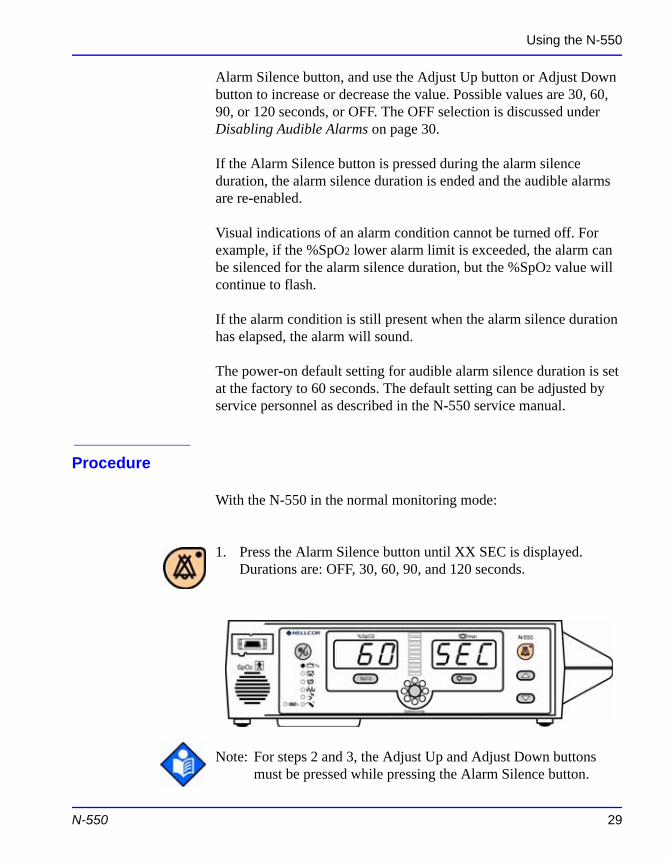
Procedure
With the N-550 in the normal monitoring mode:
1. Press the Alarm Silence button until XX SEC is displayed. Durations are: OFF, 30, 60, 90, and 120 seconds.
N-550 29
Note: For steps 2 and 3, the Adjust Up and Adjust Down buttons must be pressed while pressing the Alarm Silence button.
Using the N-550
2. While pressing the Alarm Silence button, press and hold the Adjust Up button to increase alarm silence duration to Off, 30, 60, 90, or 120 seconds.
3. While pressing the Alarm Silence button, press and hold the Adjust Down button to decrease alarm silence duration to OFF, 30, 60, 90, or 120 seconds.
Note: Releasing the Adjust Up or Adjust Down button sets the alarm silence duration.
Disabling Audible Alarms
Discussion
Setting the alarm silence duration to OFF means that the N-550 will produce no audible alarms.
Visual indications of an alarm condition are not affected by disabling the audible alarms.
The ability to set the alarm silence duration to OFF can be enabled or disabled by qualified service personnel as described in the service manual.
30
WARNING: Do not silence the audible alarm or decrease its volume if patient safety could be compromised.
Procedure
With the N-550 in the normal monitoring mode:
Using the N-550
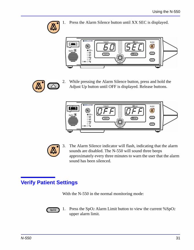
1. Press the Alarm Silence button until XX SEC is displayed.
2. While pressing the Alarm Silence button, press and hold the Adjust Up button until OFF is displayed. Release buttons.
3. The Alarm Silence indicator will flash, indicating that the alarm sounds are disabled. The N-550 will sound three beeps approximately every three minutes to warn the user that the alarm sound has been silenced.
N-550 31
Verify Patient Settings
With the N-550 in the normal monitoring mode:
1. Press the SpO2 Alarm Limit button to view the current %SpO2 upper alarm limit.
Using the N-550
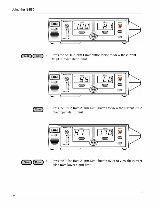
2. Press the SpO2 Alarm Limit button twice to view the current %SpO2 lower alarm limit.
3. Press the Pulse Rate Alarm Limit button to view the current Pulse Rate upper alarm limit.
32
4. Press the Pulse Rate Alarm Limit button twice to view the current Pulse Rate lower alarm limit.
Using the N-550
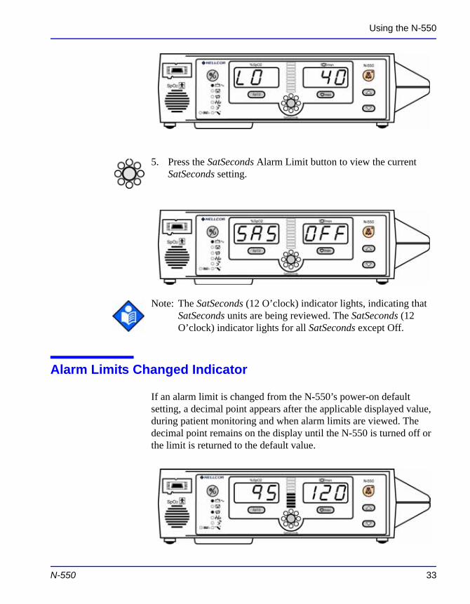
5. Press the SatSeconds Alarm Limit button to view the current SatSeconds setting.
Note: The SatSeconds (12 O’clock) indicator lights, indicating that SatSeconds units are being reviewed. The SatSeconds (12 O’clock) indicator lights for all SatSeconds except Off.
Alarm Limits Changed Indicator
If an alarm limit is changed from the N-550’s power-on default setting, a decimal point appears after the applicable displayed value, during patient monitoring and when alarm limits are viewed. The
N-550 33
decimal point remains on the display until the N-550 is turned off or the limit is returned to the default value.
Using the N-550
Alarm limits that have been changed from the default setting are identified by a decimal point (.) after the displayed reading (%SpO2 or Pulse Rate).
Setting Alarm Limits
Discussion
Alarm limits determine the upper and lower points of patient data at which the N-550 will sound an alarm.
Procedure
With the N-550 in the normal monitoring mode:
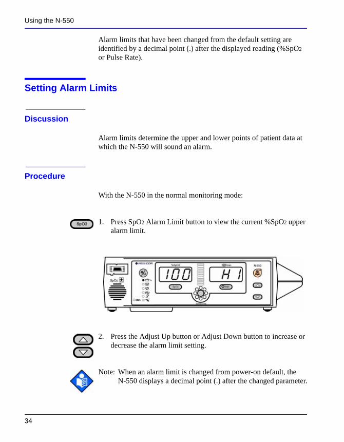
1. Press SpO2 Alarm Limit button to view the current %SpO2 upper alarm limit.
34
2. Press the Adjust Up button or Adjust Down button to increase or decrease the alarm limit setting.
Note: When an alarm limit is changed from power-on default, the N-550 displays a decimal point (.) after the changed parameter.
Using the N-550
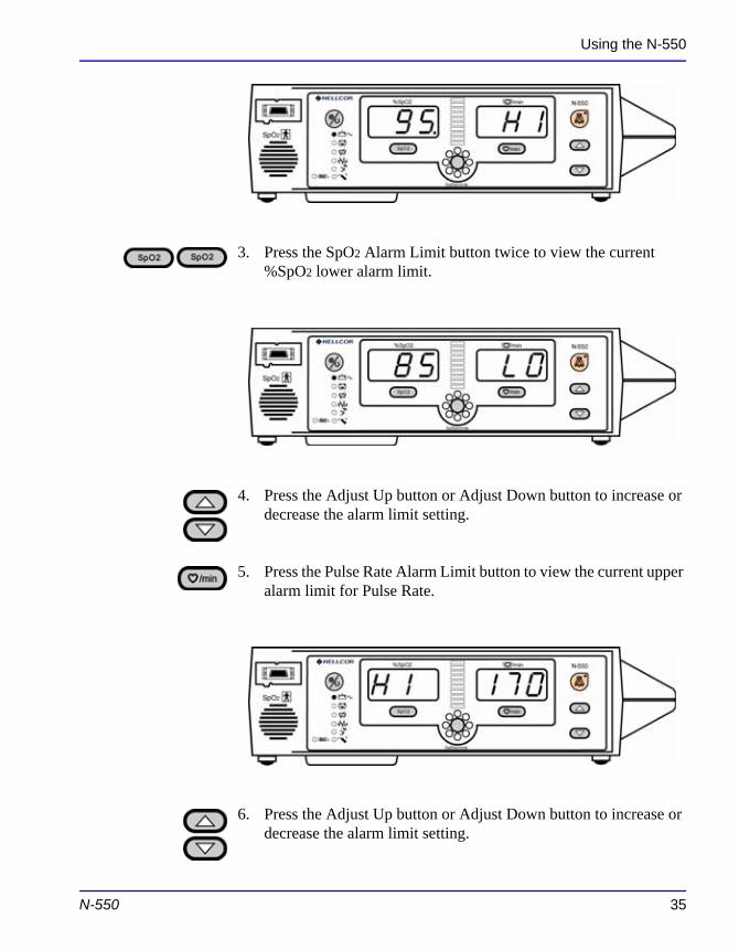
3. Press the SpO2 Alarm Limit button twice to view the current %SpO2 lower alarm limit.
4. Press the Adjust Up button or Adjust Down button to increase or decrease the alarm limit setting.
5. Press the Pulse Rate Alarm Limit button to view the current upper alarm limit for Pulse Rate.
N-550 35
6. Press the Adjust Up button or Adjust Down button to increase or decrease the alarm limit setting.
Using the N-550
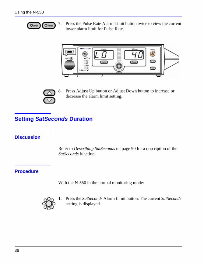
7. Press the Pulse Rate Alarm Limit button twice to view the current lower alarm limit for Pulse Rate.
8. Press Adjust Up button or Adjust Down button to increase or decrease the alarm limit setting.
Setting SatSeconds Duration
Discussion
Refer to Describing SatSeconds on page 90 for a description of the SatSeconds function.
Procedure
With the N-550 in the normal monitoring mode:
36
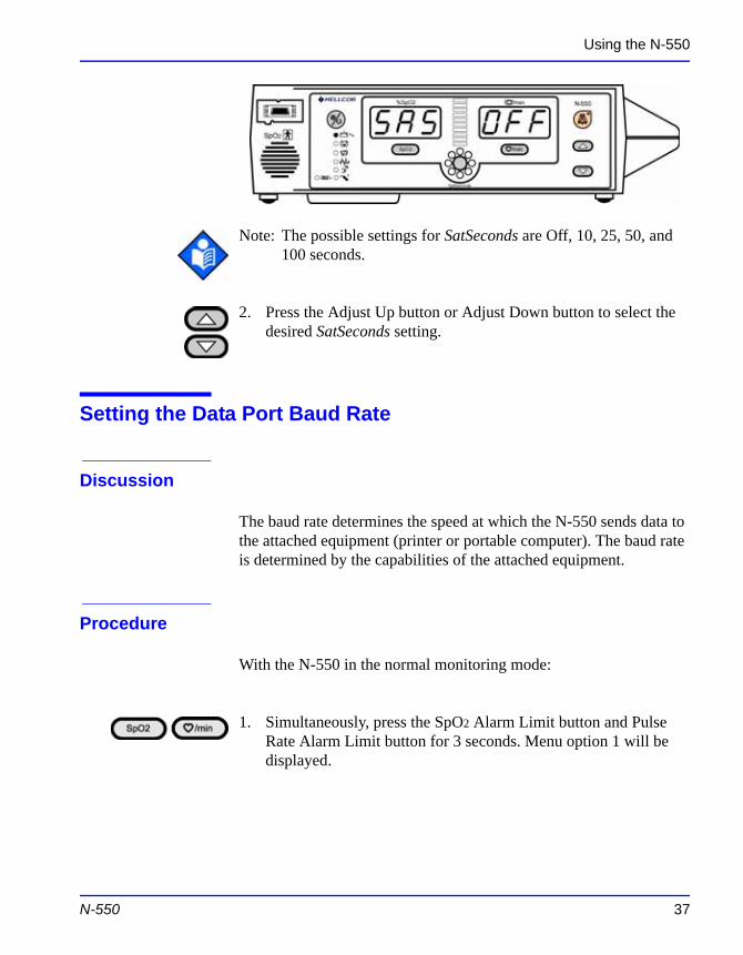
1. Press the SatSeconds Alarm Limit button. The current SatSeconds setting is displayed.
Using the N-550
Note: The possible settings for SatSeconds are Off, 10, 25, 50, and 100 seconds.
2. Press the Adjust Up button or Adjust Down button to select the desired SatSeconds setting.
Setting the Data Port Baud Rate
Discussion
The baud rate determines the speed at which the N-550 sends data to the attached equipment (printer or portable computer). The baud rate is determined by the capabilities of the attached equipment.
Procedure
With the N-550 in the normal monitoring mode:
N-550 37
1. Simultaneously, press the SpO2 Alarm Limit button and Pulse Rate Alarm Limit button for 3 seconds. Menu option 1 will be displayed.
Using the N-550
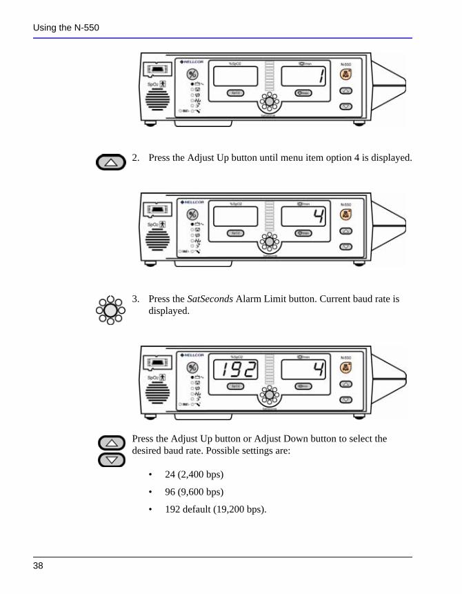
2. Press the Adjust Up button until menu item option 4 is displayed.
3. Press the SatSeconds Alarm Limit button. Current baud rate is displayed.
38
Press the Adjust Up button or Adjust Down button to select the desired baud rate. Possible settings are:
• 24 (2,400 bps)
• 96 (9,600 bps)
• 192 default (19,200 bps).
Using the N-550
Setting the Data Port Protocol
With the N-550 in the normal monitoring mode:
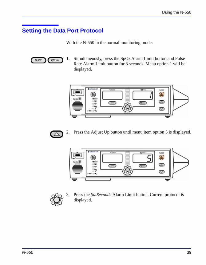
1. Simultaneously, press the SpO2 Alarm Limit button and Pulse Rate Alarm Limit button for 3 seconds. Menu option 1 will be displayed.
2. Press the Adjust Up button until menu item option 5 is displayed.
N-550 39
3. Press the SatSeconds Alarm Limit button. Current protocol is displayed.
Using the N-550
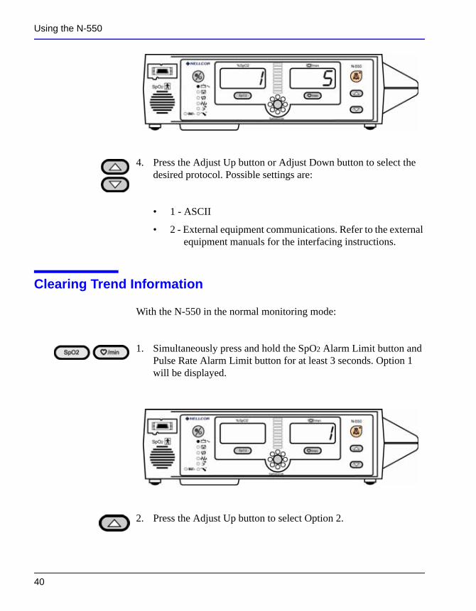
4. Press the Adjust Up button or Adjust Down button to select the desired protocol. Possible settings are:
• 1 - ASCII
• 2 - External equipment communications. Refer to the external equipment manuals for the interfacing instructions.
Clearing Trend Information
With the N-550 in the normal monitoring mode:
1. Simultaneously press and hold the SpO2 Alarm Limit button and Pulse Rate Alarm Limit button for at least 3 seconds. Option 1 will be displayed.
40
2. Press the Adjust Up button to select Option 2.
Using the N-550
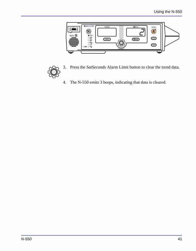
3. Press the SatSeconds Alarm Limit button to clear the trend data.
4. The N-550 emits 3 beeps, indicating that data is cleared.
N-550 41

Blank Page
N - 5 5 0 T r e n d
Trend Data Operation
From the initial measurement of a patient, trend data (a data point) is stored in memory every 4 seconds. Up to 50 alarm limit changes can also be stored in trend data. The N-550 can store up to 24 hours of trend data.
The N-550 trend data will be lost if the coin cell battery fails or is removed. The coin cell battery is located on the main circuit board.
CAUTION: Changing alarm limit settings uses trend memory space. Change alarm limits only as needed.
Note: Trend memory always contains the most recent 24 hours of data, with newly collected data overwriting the oldest data on a rolling basis. The N-550 continues to record data points as long as the N-550 is powered on and an initial patient measurement has been made, with “blank” data points collected if no sensor is connected to the N-550 or patient. “Blank” data will overwrite older patient data if the memory becomes full. Therefore, if you want to save old patient data, it is important that you turn your N-550 off when you are not monitoring a patient, and that you download the trend memory before it fills
N-550 43
up and overwrites the old data with new data (or “blank” data).
Trend Data
Trend data information may be retrieved or cleared through the N-550 data port using options available in a display menu.
N-550 Trend
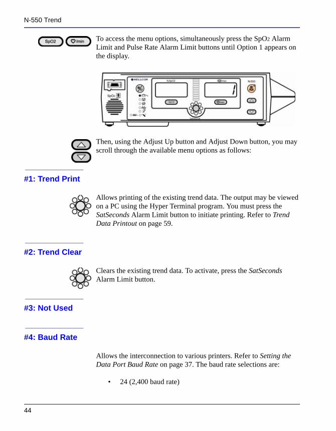
To access the menu options, simultaneously press the SpO2 Alarm Limit and Pulse Rate Alarm Limit buttons until Option 1 appears on the display.
Then, using the Adjust Up button and Adjust Down button, you may scroll through the available menu options as follows:
#1: Trend Print
Allows printing of the existing trend data. The output may be viewed on a PC using the Hyper Terminal program. You must press the SatSeconds Alarm Limit button to initiate printing. Refer to Trend Data Printout on page 59.
#2: Trend Clear
Clears the existing trend data. To activate, press the SatSeconds Alarm Limit button.
44
#3: Not Used
#4: Baud Rate
Allows the interconnection to various printers. Refer to Setting the Data Port Baud Rate on page 37. The baud rate selections are:
• 24 (2,400 baud rate)
N-550 Trend
• 96 (9,600 baud rate)
• 192 default (19,200 baud rate)
#5: Data Port Printout
Selections are as follows:
Option 1
Printout in ASCII characters.
Option 2
External equipment communications. Refer to the external equipment manual for the interfacing instructions.
N-550 45

Blank Page
U s i n g t h e D a t a P o r t
Overview
Patient data can be obtained through the data port on the back of the N-550 by connecting it to an attached PC or serial printer.
When connecting the N-550 to a printer or PC, verify proper operation before clinical use. Both the N-550 and the printer or PC must be connected to a grounded AC outlet. The N-550 protocol setting must be ASCII.
Any printer or PC connected to the N-550's data port must be certified according to IEC Standard 60950. All combinations of equipment must be in compliance with IEC Standard 60601-1-1 systems requirements. Anyone who connects a printer or PC to the data output port configures a medical system and is therefore responsible for ensuring that the system complies with the requirements of system standard IEC Standard 60601-1-1 and the electromagnetic compatibility system standard IEC Standard 60601-1-2.
Connecting to the Data Port
The N-550 data port may be connected to the printer or PC by using a cable terminated with an AMP connector (AMP part number
N-550 47
747538-1), ferrule (AMP part number 1-747579-2), and compatible pins (AMP part number 66570-2). The cable should be no more than 25 feet (7.6 meters) in length. The external ITE (Information Technology Equipment) device must be certified to UL-1950 or IEC-60950.
Using the Data Port
The cable used must have a braided shield providing 100% coverage, such as a Belden cable (Belden part number 9609) or equivalent. The shield must have a 360-degree connection to the metal shell on the N-550's DB-15 connector and to the connector on the PC or serial printer. Do not create sharp bends in the cable, as this may tear or break the shielding.
No hardware flow control is used. However, in the ASCII mode, XON/XOFF flow control is supported.
Data Port Pinouts
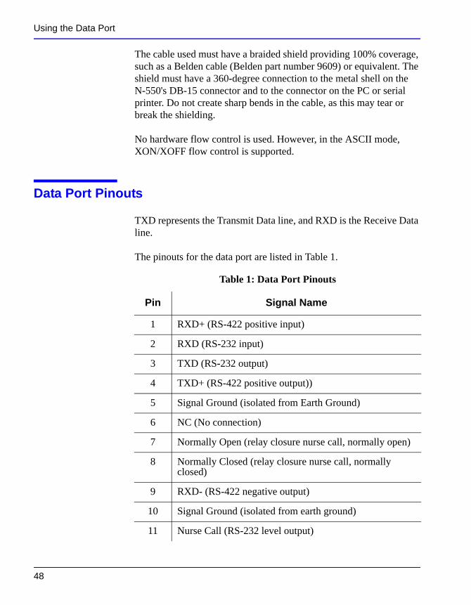
TXD represents the Transmit Data line, and RXD is the Receive Data line.
The pinouts for the data port are listed in Table 1.
Table 1: Data Port Pinouts
Pin Signal Name
1 RXD+ (RS-422 positive input)
2 RXD (RS-232 input)
3 TXD (RS-232 output)
4 TXD+ (RS-422 positive output))
5 Signal Ground (isolated from Earth Ground)
6 NC (No connection)
48
7 Normally Open (relay closure nurse call, normally open)
8 Normally Closed (relay closure nurse call, normally closed)
9 RXD- (RS-422 negative output)
10 Signal Ground (isolated from earth ground)
11 Nurse Call (RS-232 level output)
Using the Data Port
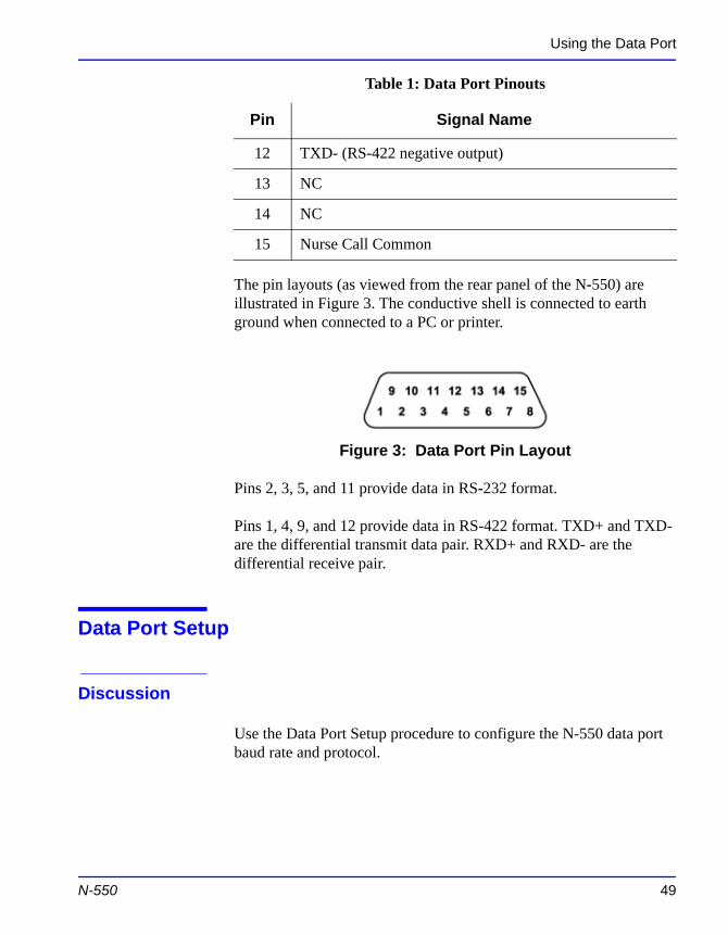
The pin layouts (as viewed from the rear panel of the N-550) are illustrated in Figure 3. The conductive shell is connected to earth ground when connected to a PC or printer.
Figure 3: Data Port Pin Layout
Pins 2, 3, 5, and 11 provide data in RS-232 format.
Pins 1, 4, 9, and 12 provide data in RS-422 format. TXD+ and TXD- are the differential transmit data pair. RXD+ and RXD- are the differential receive pair.
Data Port Setup
12 TXD- (RS-422 negative output)
13 NC
14 NC
15 Nurse Call Common
Table 1: Data Port Pinouts
Pin Signal Name
N-550 49
Discussion
Use the Data Port Setup procedure to configure the N-550 data port baud rate and protocol.
Using the Data Port
Procedure
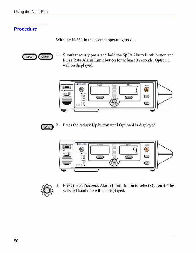
With the N-550 in the normal operating mode:
1. Simultaneously press and hold the SpO2 Alarm Limit button and Pulse Rate Alarm Limit button for at least 3 seconds. Option 1 will be displayed.
2. Press the Adjust Up button until Option 4 is displayed.
50
3. Press the SatSeconds Alarm Limit Button to select Option 4. The selected baud rate will be displayed.
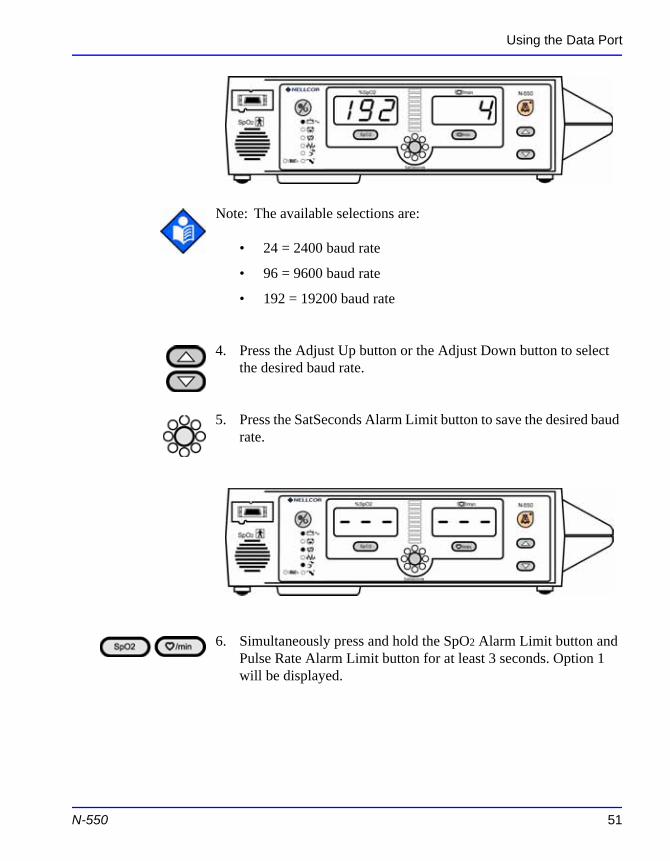
Using the Data Port
Note: The available selections are:
• 24 = 2400 baud rate
• 96 = 9600 baud rate
• 192 = 19200 baud rate
4. Press the Adjust Up button or the Adjust Down button to select the desired baud rate.
5. Press the SatSeconds Alarm Limit button to save the desired baud rate.
N-550 51
6. Simultaneously press and hold the SpO2 Alarm Limit button and Pulse Rate Alarm Limit button for at least 3 seconds. Option 1 will be displayed.
Using the Data Port
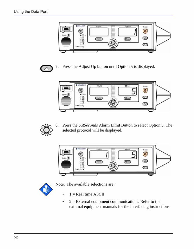
7. Press the Adjust Up button until Option 5 is displayed.
8. Press the SatSeconds Alarm Limit Button to select Option 5. The selected protocol will be displayed.
52
Note: The available selections are:
• 1 = Real time ASCII
• 2 = External equipment communications. Refer to the external equipment manuals for the interfacing instructions.
Using the Data Port
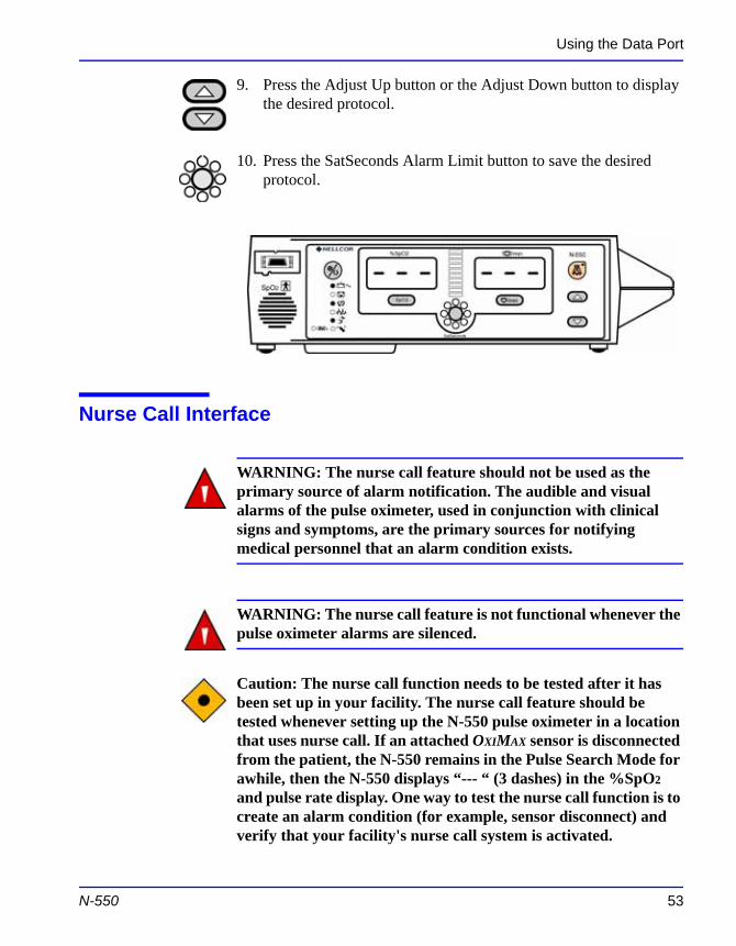
9. Press the Adjust Up button or the Adjust Down button to display the desired protocol.
10. Press the SatSeconds Alarm Limit button to save the desired protocol.
Nurse Call Interface
WARNING: The nurse call feature should not be used as the primary source of alarm notification. The audible and visual alarms of the pulse oximeter, used in conjunction with clinical signs and symptoms, are the primary sources for notifying medical personnel that an alarm condition exists.
WARNING: The nurse call feature is not functional whenever the pulse oximeter alarms are silenced.
N-550 53
Caution: The nurse call function needs to be tested after it has been set up in your facility. The nurse call feature should be tested whenever setting up the N-550 pulse oximeter in a location that uses nurse call. If an attached OXIMAX sensor is disconnected from the patient, the N-550 remains in the Pulse Search Mode for awhile, then the N-550 displays “--- “ (3 dashes) in the %SpO2 and pulse rate display. One way to test the nurse call function is to create an alarm condition (for example, sensor disconnect) and verify that your facility's nurse call system is activated.
Using the Data Port
The nurse call feature of the N-550 is operational when the N-550 is powered by AC power or battery power. The nurse call feature of the N-550 works in conjunction with the nurse call system of your institution when the N-550 sounds an audible alarm.
The N-550 provides two different types of nurse call interfaces: an RS-232 format and relay closure. Both interfaces function when the N-550 is operating either on AC power or battery power.
The remote location is signaled anytime there is an audible alarm. If the audible alarm has been turned off or silenced, the nurse call function is also turned off.
Pin 11 on the data port is the RS-232 level nurse call signal and pin 5 or 10 is ground (see Table 1 on page 48). When there is no alarm condition, the voltage between pins 10 and 11 is -5 to -12 VDC. Whenever the N-550 is in an alarm condition, the output between pins 10 and 11 is +5 to +12 VDC. This is the default condition (normally low). There is a service menu to change the default condition. Refer to the N-550 service manual for the procedure.
Pins 7 and 15 provide a relay that closes when an alarm is sounding on the N-550. Pins 8 and 15 provide a relay that opens when an alarm is sounding. Pin 15 is a common lead for both relays.
Note: When the relay is closed there is approximately 27 ohms of resistance.
Setting Nurse Call RS-232 Polarity
54
The nurse call polarity can be set to a high signal on an N-550 alarm condition or a low signal on an N-550 alarm condition. Refer to the N-550 service manual for setting the Nurse Call RS-232 polarity.
Setting Nurse Call Relays Normally Open/Closed
Data port pins 7 and 15 provide a relay that closes (nominally 27 ohms) when an alarm is sounding on the N-550. Pins 8 and 15

Using the Data Port
provide a relay that opens when an alarm is sounding. Pin 15 is a common lead for both relays. The relay operates whether the N-550 is operating on AC power or battery.
N-550 55

Blank Page
P r i n t i n g
Printing N-550 Real-Time Data
Real-time data is continuously sent to the data port on the back of the N-550. Patient data can be obtained through the data port by connecting to a computer or serial printer. When a real-time printout or display is being transmitted to a printer or computer, a new line is printed/displayed every 2 seconds. Column headings are printed/displayed every 25 lines, or if one of the values in the column heading is changed.
Note: If the data output stops transmitting, the N-550 must be turned off and then turned back on.
When connecting the N-550 to a printer or computer, verify proper operation before clinical use. Both the N-550 and the printer or PC must be connected to a grounded AC outlet.
Any printer or computer connected to the N-550's data port must be certified according to IEC Standard 60950. All combinations of equipment must be in compliance with IEC Standard 60601-1-1 systems requirements. Anyone who connects a printer or PC to the data output port configures a medical system and is therefore responsible that the system complies with the requirements of system standard IEC Standard 60601-1-1 and the electromagnetic compatibility system standard IEC Standard 60601-1-2.
N-550 57
Printing
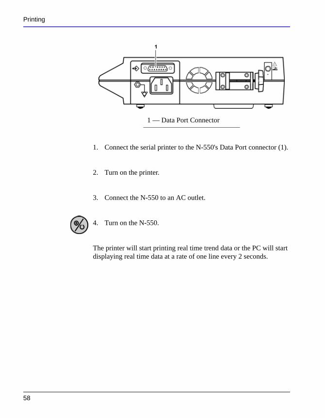
1. Connect the serial printer to the N-550's Data Port connector (1).
2. Turn on the printer.
3. Connect the N-550 to an AC outlet.
4. Turn on the N-550.
The printer will start printing real time trend data or the PC will start displaying real time data at a rate of one line every 2 seconds.
1 — Data Port Connector
58
Printing
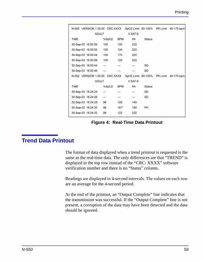
Figure 4: Real-Time Data Printout
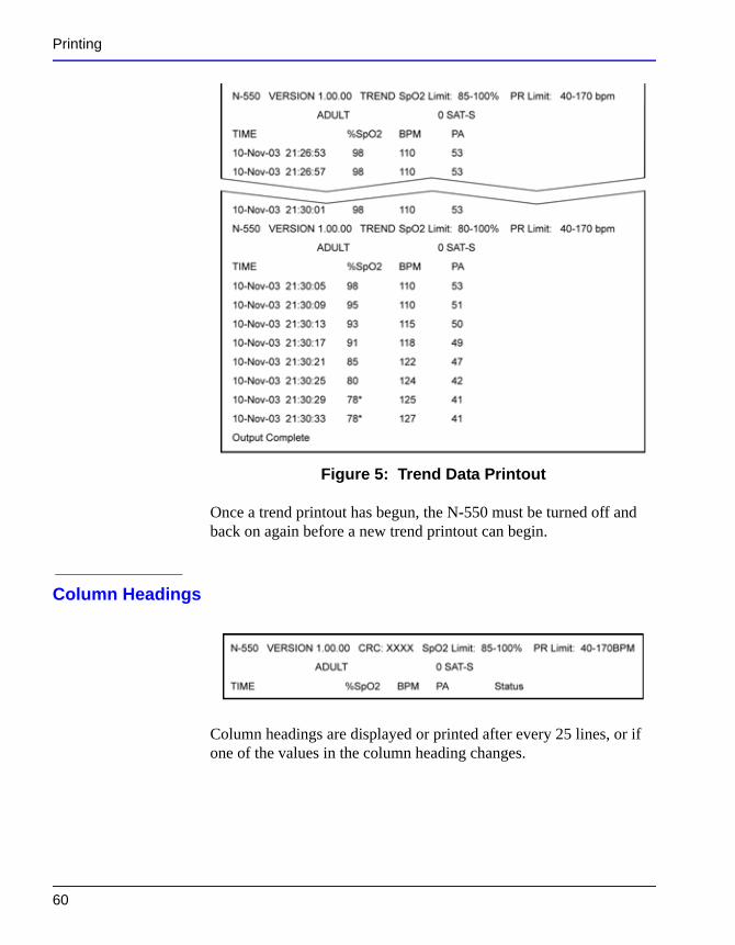
Trend Data Printout
The format of data displayed when a trend printout is requested is the same as the real-time data. The only differences are that “TREND” is displayed in the top row instead of the “CRC: XXXX” software verification number and there is no “Status” column.
Readings are displayed in 4-second intervals. The values on each row are an average for the 4-second period.
N-550 59
At the end of the printout, an “Output Complete” line indicates that the transmission was successful. If the “Output Complete” line is not present, a corruption of the data may have been detected and the data should be ignored.
Printing
Figure 5: Trend Data Printout
Once a trend printout has begun, the N-550 must be turned off and back on again before a new trend printout can begin.
Column Headings
60
Column headings are displayed or printed after every 25 lines, or if one of the values in the column heading changes.
Printing
Data Source
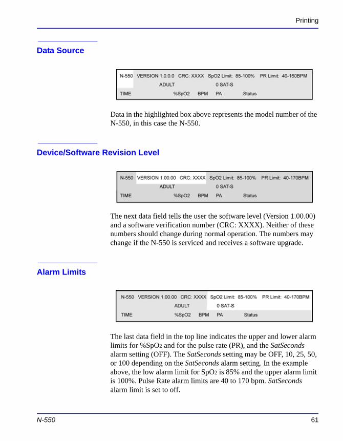
Data in the highlighted box above represents the model number of the N-550, in this case the N-550.
Device/Software Revision Level
The next data field tells the user the software level (Version 1.00.00) and a software verification number (CRC: XXXX). Neither of these numbers should change during normal operation. The numbers may change if the N-550 is serviced and receives a software upgrade.
Alarm Limits
N-550 61
The last data field in the top line indicates the upper and lower alarm limits for %SpO2 and for the pulse rate (PR), and the SatSeconds alarm setting (OFF). The SatSeconds setting may be OFF, 10, 25, 50, or 100 depending on the SatSeconds alarm setting. In the example above, the low alarm limit for SpO2 is 85% and the upper alarm limit is 100%. Pulse Rate alarm limits are 40 to 170 bpm. SatSeconds alarm limit is set to off.
Printing
N-550 Mode
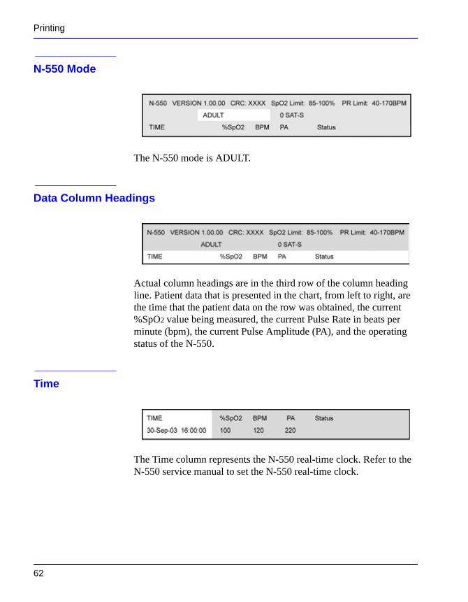
The N-550 mode is ADULT.
Data Column Headings
Actual column headings are in the third row of the column heading line. Patient data that is presented in the chart, from left to right, are the time that the patient data on the row was obtained, the current %SpO2 value being measured, the current Pulse Rate in beats per minute (bpm), the current Pulse Amplitude (PA), and the operating status of the N-550.
Time
62
The Time column represents the N-550 real-time clock. Refer to the N-550 service manual to set the N-550 real-time clock.
Printing
Patient Data
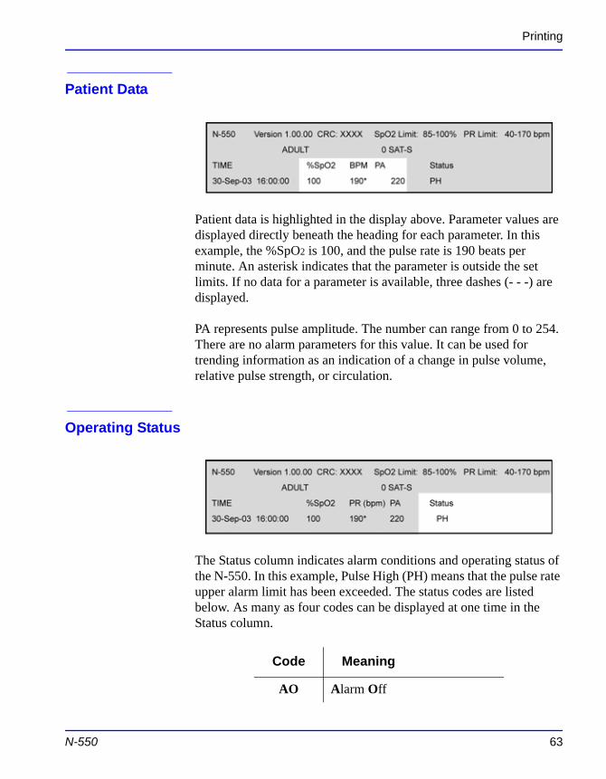
Patient data is highlighted in the display above. Parameter values are displayed directly beneath the heading for each parameter. In this example, the %SpO2 is 100, and the pulse rate is 190 beats per minute. An asterisk indicates that the parameter is outside the set limits. If no data for a parameter is available, three dashes (- - -) are displayed.
PA represents pulse amplitude. The number can range from 0 to 254. There are no alarm parameters for this value. It can be used for trending information as an indication of a change in pulse volume, relative pulse strength, or circulation.
Operating Status
N-550 63
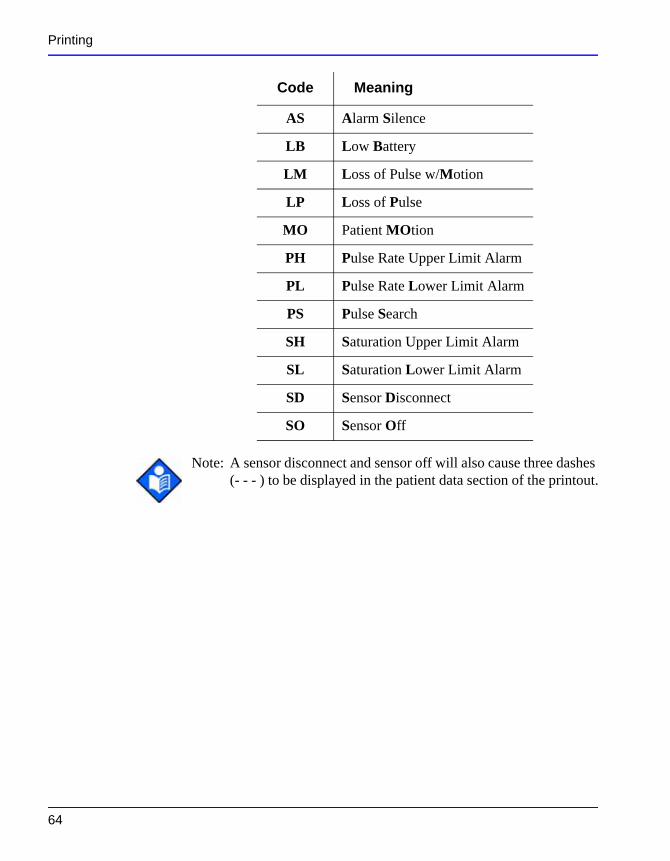
The Status column indicates alarm conditions and operating status of the N-550. In this example, Pulse High (PH) means that the pulse rate upper alarm limit has been exceeded. The status codes are listed below. As many as four codes can be displayed at one time in the Status column.
Code Meaning
AO Alarm Off
Printing
Note: A sensor disconnect and sensor off will also cause three dashes (- - - ) to be displayed in the patient data section of the printout.
AS Alarm Silence
LB Low Battery
LM Loss of Pulse w/Motion
LP Loss of Pulse
MO Patient MOtion
PH Pulse Rate Upper Limit Alarm
PL Pulse Rate Lower Limit Alarm
PS Pulse Search
SH Saturation Upper Limit Alarm
SL Saturation Lower Limit Alarm
SD Sensor Disconnect
SO Sensor Off
Code Meaning
64
Sensors and Accessories
S e n s o r s a n d A c c e s s o r i e s
Selecting a Sensor
WARNING: Before use, carefully read the sensor directions for use, including all warnings, cautions, and instructions.
WARNING: Do not use a damaged sensor or pulse oximetry cable. Do not use a sensor with exposed optical components.
WARNING: Use only Nellcor sensors and pulse oximetry cables with the N-550. Other sensors or pulse oximetry cables may cause improper N-550 performance.
WARNING: Use only one pulse oximetry cable to increase the length of the sensor. Use of more than one pulse oximetry cable may have an adverse effect on performance. Do not attach any cable that is intended for computer use to the sensor port.
WARNING: Pulse oximetry readings and pulse signal can be
N-550 65
affected by certain ambient environmental conditions, sensor application errors, and certain patient conditions.
WARNING: Tissue damage can be caused by incorrect application or duration of use of an SpO2 sensor. Inspect the sensor site as directed in the sensor directions for use.
Sensors and Accessories
WARNING: Do not immerse or wet the sensor.
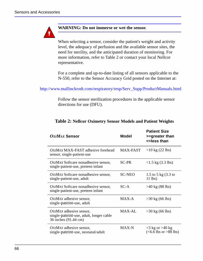
When selecting a sensor, consider the patient's weight and activity level, the adequacy of perfusion and the available sensor sites, the need for sterility, and the anticipated duration of monitoring. For more information, refer to Table 2 or contact your local Nellcor representative.
For a complete and up-to-date listing of all sensors applicable to the N-550, refer to the Sensor Accuracy Grid posted on the Internet at:
http://www.mallinckrodt.com/respiratory/resp/Serv_Supp/ProductManuals.html
Follow the sensor sterilization procedures in the applicable sensor directions for use (DFU).
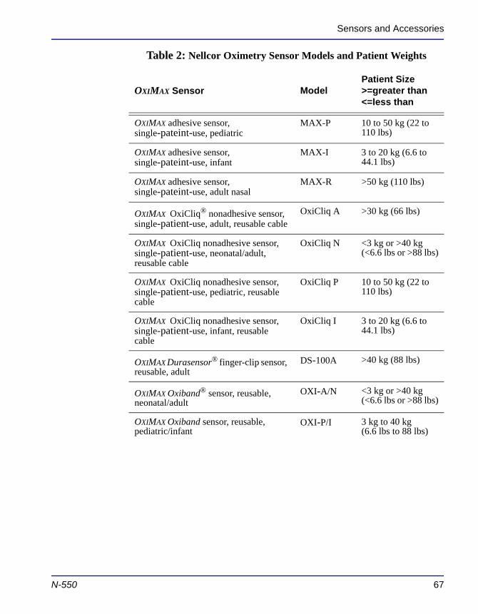
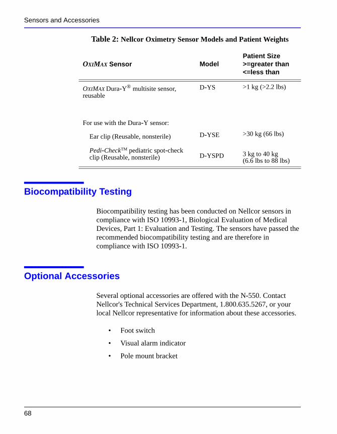
Table 2: Nellcor Oximetry Sensor Models and Patient Weights
OXIMAX Sensor ModelPatient Size>=greater than<=less than
OXIMAX MAX-FAST adhesive forehead sensor, single-patient-use
MAX-FAST >10 kg (22 lbs)
OXIMAX Softcare nonadhesive sensor, single-patient-use, preteen infant
SC-PR <1.5 kg (3.3 lbs)
OXIMAX Softcare nonadhesive sensor, single-patient-use, adult
SC-NEO 1.5 to 5 kg (3.3 to 11 lbs)
66
OXIMAX Softcare nonadhesive sensor, single-patient-use, preteen infant
SC-A >40 kg (88 lbs)
OXIMAX adhesive sensor, single-pateint-use, adult
MAX-A >30 kg (66 lbs)
OXIMAX adhesive sensor, single-pateint-use, adult, longer cable 36 inches (91.44 cm)
MAX-AL >30 kg (66 lbs)
OXIMAX adhesive sensor, single-pateint-use, neonatal/adult
MAX-N <3 kg or >40 kg (<6.6 lbs or >88 lbs)
Sensors and Accessories
OXIMAX adhesive sensor, single-pateint-use, pediatric
MAX-P 10 to 50 kg (22 to 110 lbs)
OXIMAX adhesive sensor, single-pateint-use, infant
MAX-I 3 to 20 kg (6.6 to 44.1 lbs)
OXIMAX adhesive sensor, single-pateint-use, adult nasal
MAX-R >50 kg (110 lbs)
OXIMAX OxiCliq® nonadhesive sensor, single-patient-use, adult, reusable cable
OxiCliq A >30 kg (66 lbs)
OXIMAX OxiCliq nonadhesive sensor, single-patient-use, neonatal/adult, reusable cable
OxiCliq N <3 kg or >40 kg (<6.6 lbs or >88 lbs)
OXIMAX OxiCliq nonadhesive sensor, single-patient-use, pediatric, reusable cable
OxiCliq P 10 to 50 kg (22 to 110 lbs)
OXIMAX OxiCliq nonadhesive sensor, single-patient-use, infant, reusable cable
OxiCliq I 3 to 20 kg (6.6 to 44.1 lbs)
OXIMAX Durasensor® finger-clip sensor, reusable, adult
DS-100A >40 kg (88 lbs)
OXIMAX Oxiband® sensor, reusable, neonatal/adult
OXI-A/N <3 kg or >40 kg (<6.6 lbs or >88 lbs)
OXIMAX Oxiband sensor, reusable, pediatric/infant
OXI-P/I 3 kg to 40 kg (6.6 lbs to 88 lbs)
Table 2: Nellcor Oximetry Sensor Models and Patient Weights
OXIMAX Sensor ModelPatient Size>=greater than<=less than
N-550 67
Sensors and Accessories
Biocompatibility Testing
Biocompatibility testing has been conducted on Nellcor sensors in compliance with ISO 10993-1, Biological Evaluation of Medical Devices, Part 1: Evaluation and Testing. The sensors have passed the recommended biocompatibility testing and are therefore in compliance with ISO 10993-1.
Optional Accessories
Several optional accessories are offered with the N-550. Contact Nellcor's Technical Services Department, 1.800.635.5267, or your
OXIMAX Dura-Y® multisite sensor, reusable
For use with the Dura-Y sensor:
Ear clip (Reusable, nonsterile)
Pedi-CheckTM pediatric spot-check clip (Reusable, nonsterile)
D-YS
D-YSE
D-YSPD
>1 kg (>2.2 lbs)
>30 kg (66 lbs)
3 kg to 40 kg (6.6 lbs to 88 lbs)
Table 2: Nellcor Oximetry Sensor Models and Patient Weights
OXIMAX Sensor ModelPatient Size>=greater than<=less than
68
local Nellcor representative for information about these accessories.
• Foot switch
• Visual alarm indicator
• Pole mount bracket
Sensors and Accessories
Accessories for the N-550 are listed on the Internet at:
http://www.mallinckrodt.com/respiratory/resp/Serv_Supp/Apartweb/main/PartAcceMenu.html
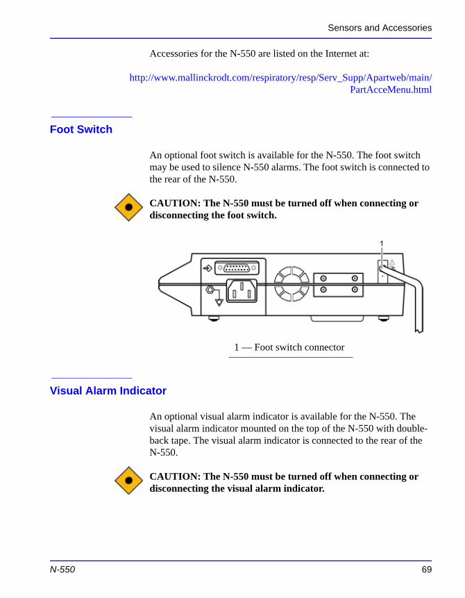
Foot Switch
An optional foot switch is available for the N-550. The foot switch may be used to silence N-550 alarms. The foot switch is connected to the rear of the N-550.
CAUTION: The N-550 must be turned off when connecting or disconnecting the foot switch.
Visual Alarm Indicator
An optional visual alarm indicator is available for the N-550. The
1 — Foot switch connector
N-550 69
visual alarm indicator mounted on the top of the N-550 with double-back tape. The visual alarm indicator is connected to the rear of the N-550.
CAUTION: The N-550 must be turned off when connecting or disconnecting the visual alarm indicator.
Sensors and Accessories
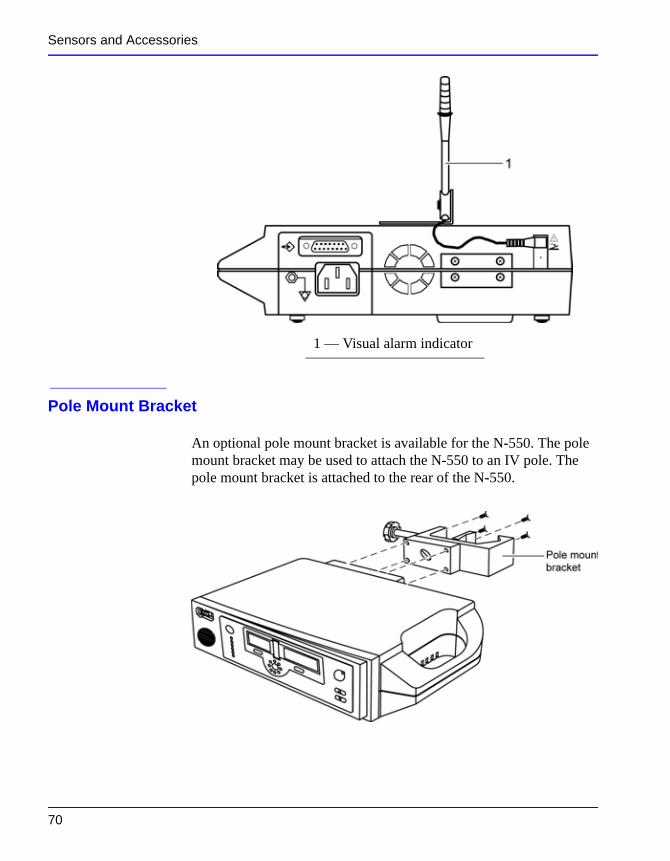
Pole Mount Bracket
An optional pole mount bracket is available for the N-550. The pole mount bracket may be used to attach the N-550 to an IV pole. The pole mount bracket is attached to the rear of the N-550.
1 — Visual alarm indicator
70
P e r f o r m a n c e C o n s i d e r a t i o n s
WARNING: Pulse oximetry readings and pulse signals can be affected by certain ambient environmental conditions, sensor application errors, and certain patient conditions. See the appropriate sections of the manual for specific safety information.
Performance Verification
The performance of the N-550 can be verified by following the procedures outlined in the Performance Verification section of the N-550 service manual. Qualified service personnel should perform these procedures before using the N-550 for the first time in a clinical setting.
N-550 Performance Considerations
Certain patient conditions can affect the measurements of the N-550 and cause the loss of the pulse signal.
Inaccurate measurements can be caused by:
• prolonged patient movement
N-550 71
• venous pulsations
• intravascular dyes, such as indocyanine green or methylene blue
• defibrillation
Performance Considerations
Dysfunctional Hemoglobins
Dysfunctional hemoglobins such as carboxyhemoglobin, methemoglobin, and sulphemoglobin are unable to carry oxygen. SpO2 readings may appear normal; however, a patient may be hypoxic because less hemoglobin is available to carry oxygen. Further assessment beyond pulse oximetry is recommended.
Anemia
Anemia causes decreased arterial oxygen content. Although SpO2 readings may appear normal, an anemic patient may be hypoxic. Correcting anemia can improve arterial oxygen content. The pulse oximeter may fail to provide an SpO2 if hemoglobin levels fall below 5 gm/dl.
Saturation
The N-550 will only measure saturation levels between 1 and 100%.
Pulse rates
The N-550 will only measure pulse rates between 20 and 250 beats per minute. Detected pulse rates outside the range of 20 to 250 beats per minute are displayed as the closest value within the range.
72
Sensor Performance Considerations
WARNING: Pulse oximetry readings and pulse signal can be affected by certain ambient conditions, sensor application errors, and certain patient conditions.
Performance Considerations
Inaccurate measurements can be caused by:
• incorrect application of the sensor
• placement of the sensor on an extremity with a blood pressure cuff, arterial catheter, or intravascular line
• ambient light
• prolonged patient movement
Loss-of-pulse signal can occur for the following reasons:
• the sensor is applied too tightly
• a blood pressure cuff is inflated on the same extremity as the one with the sensor attached
• there is arterial occlusion proximal to the sensor
Use only Nellcor sensors and sensor cables.
WARNING: The use of accessories, sensors, and cables other than those specified may result in increased emission and/or decreased immunity and inaccurate readings of the N-550 pulse oximeter.
Select an appropriate sensor, apply it as directed, and observe all warnings and cautions presented in the directions for use accompanying the sensor. Clean and remove any substances such as nail polish from the application site. Periodically check to ensure that the sensor remains properly positioned on the patient.
N-550 73
WARNING: Tissue damage can be caused by incorrect application or inappropriate duration of use of an SpO2 sensor. Inspect the sensor site as directed in the sensor directions for use.
Performance Considerations
High ambient light sources such as surgical lights (especially those with a xenon light source), bilirubin lamps, fluorescent lights, infrared heating lamps, and direct sunlight can interfere with the performance of an SpO2 sensor. To prevent interference from ambient light, ensure that the sensor is properly applied and cover the sensor site with opaque material.
Caution:Failure to cover the sensor site with opaque material in high ambient light conditions may result in inaccurate measurements.
If patient movement presents a problem, try one or more of the following remedies to correct the problem.
• verify that the sensor is properly and securely applied
• move the sensor to a less active site
• use an adhesive sensor that tolerates some patient motion
• use a new sensor with fresh adhesive backing
If poor perfusion affects performance, consider using the OXIMAX MAX-R sensor; it obtains measurements from the nasal septal anterior ethmoid artery, an artery supplied by the internal carotid artery. This sensor may obtain measurements when peripheral perfusion is relatively poor.
74
O p e r a t o r ’s M e n u
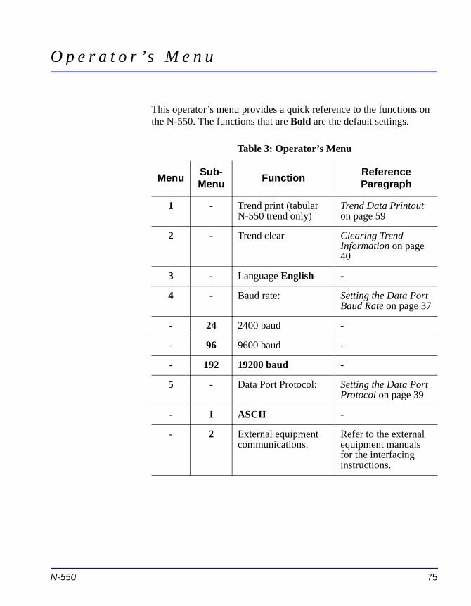
This operator’s menu provides a quick reference to the functions on the N-550. The functions that are Bold are the default settings.
Table 3: Operator’s Menu
Menu Sub-Menu Function Reference
Paragraph
1 - Trend print (tabular N-550 trend only)
Trend Data Printout on page 59
2 - Trend clear Clearing Trend Information on page 40
3 - Language English -
4 - Baud rate: Setting the Data Port Baud Rate on page 37
- 24 2400 baud -
- 96 9600 baud -
- 192 19200 baud -
5 - Data Port Protocol: Setting the Data Port Protocol on page 39
- 1 ASCII -
N-550 75
- 2 External equipment communications.
Refer to the external equipment manuals for the interfacing instructions.

Blank Page
T r o u b l e s h o o t i n g
WARNING: If you are uncertain about the accuracy of any measurement, check the patient's vital signs by alternate means; then make sure the N-550 is functioning correctly.
WARNING: The cover should be removed only by qualified service personnel. There are no user-serviceable parts inside.
CAUTION: Do not spray, pour, or spill any liquid on the N-550, its accessories, connectors, switches, or openings in the chassis.
Error Codes
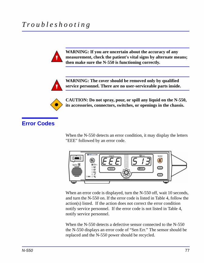
When the N-550 detects an error condition, it may display the letters "EEE" followed by an error code.
N-550 77
When an error code is displayed, turn the N-550 off, wait 10 seconds, and turn the N-550 on. If the error code is listed in Table 4, follow the action(s) listed. If the action does not correct the error condition notify service personnel. If the error code is not listed in Table 4, notify service personnel.
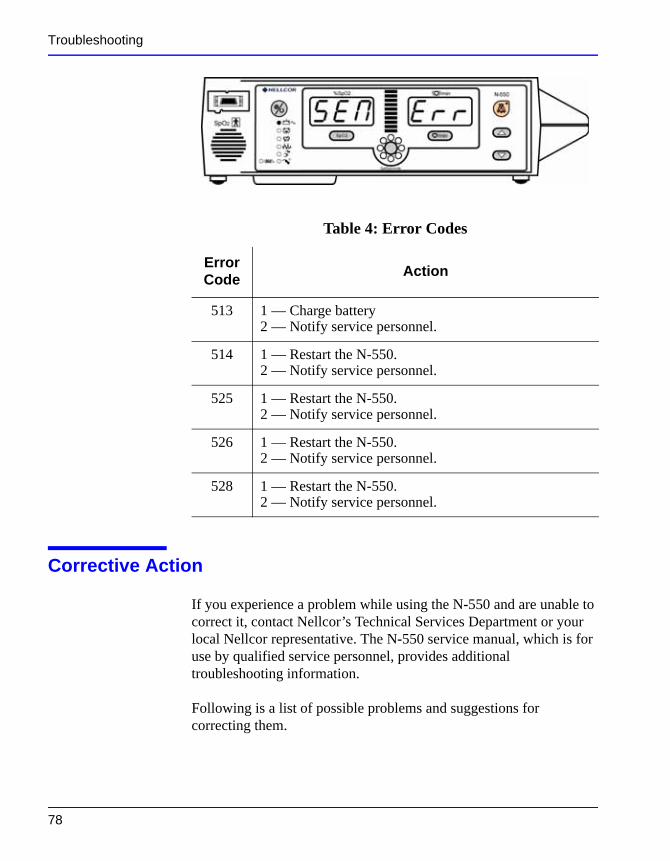
When the N-550 detects a defective sensor connected to the N-550 the N-550 displays an error code of “Sen Err.” The sensor should be replaced and the N-550 power should be recycled.
Troubleshooting
Corrective Action
If you experience a problem while using the N-550 and are unable to
Table 4: Error Codes
Error Code Action
513 1 — Charge battery2 — Notify service personnel.
514 1 — Restart the N-550.2 — Notify service personnel.
525 1 — Restart the N-550.2 — Notify service personnel.
526 1 — Restart the N-550.2 — Notify service personnel.
528 1 — Restart the N-550.2 — Notify service personnel.
78
correct it, contact Nellcor’s Technical Services Department or your local Nellcor representative. The N-550 service manual, which is for use by qualified service personnel, provides additional troubleshooting information.
Following is a list of possible problems and suggestions for correcting them.
Troubleshooting
1. There is no response to the Power On/Off button.
• If the N-550 is operating on AC power, the fuse may be blown. Notify service personnel to check and, if necessary, replace the fuse.
• If the N-550 is on battery power, the battery fuse may require replacement, the battery may be missing, or the battery may be discharged. Charge the battery or notify service personnel to replace the battery or the battery fuse, as required.
2. One or more display segments or indicators do not light during the power-on self-test.
• Do not use the N-550; contact qualified service personnel or your local Nellcor representative.
3. The N-550 does not sound a tone indicating successful completion of the Power-On Self-Test (POST).
• The N-550 has failed the power-on self-test. Do not use the N-550. This tone not only indicates the successful completion of POST, but it confirms that the audible alarm is functional. Contact qualified service personnel or your local Nellcor representative.
N-550 79
4. The Pulse Search indicator is lit for more than 10 seconds while the sensor is connected to the patient.
• Check the sensor directions for use to determine if an appropriate sensor is being used and if it is applied properly. Check sensor and sensor cable connections. Test the sensor on someone else. Try another sensor or sensor cable.
Troubleshooting
• Perfusion may be too low for the N-550 to track the pulse. Check the patient. Test the N-550 on someone else. Change the sensor site. Try another type of sensor.
• Excessive patient motion may be preventing the N-550 from tracking the pulse. Keep the patient still, if possible. Verify that the sensor is securely applied, and replace it if necessary. Change the sensor site. Use a type of sensor that tolerates more patient movement (for example, an adhesive sensor).
• The sensor may be too tight, there may be excessive ambient light, or the sensor may be on an extremity with a blood pressure cuff, arterial catheter, or intravascular line. Reposition the sensor, as necessary.
• Excessive environmental motion or electromagnetic interference may be preventing the N-550 from tracking the pulse. Remove the source of interference or try to stabilize the environment, or do both.
5. The Pulse Search indicator lights after successful measurements have been made.
• Check the patient.
• Perfusion may be too low for the N-550 to track the pulse. Test the N-550 on someone else. Change the sensor site. Try another type of sensor. Refer to Sensor Performance Considerations on page 72.
• Prolonged patient motion may be preventing the N-550 from tracking the pulse. Verify that the sensor is securely applied
80
and replace it if necessary. Change the sensor site. Use a type of sensor that tolerates more patient movement (for example, an adhesive sensor).
• The sensor may be too tight, there may be excessive ambient light, or the sensor may be on an extremity with a blood pressure cuff, arterial catheter, or intravascular line. Reposition the sensor, as necessary.
• Excessive environmental motion or electromagnetic interference may be preventing the N-550 from tracking the
Troubleshooting
pulse. Remove the source of interference or try to stabilize the environment, or do both.
6. The letters EEE, followed by a number, appear on the display.
• This is an error code. To confirm, press the Power On/Off button to turn the N-550 off, then press the button again to turn it back on. If the display shows the error code once again, record the number and provide that information to qualified service personnel, or your local Nellcor representative.
• Error Code “EEE 513" is displayed when the battery is discharged to a critically low level. Turn the N-550 off and let it charge for about 10 minutes and then turn the N-550 back on. If the error code is still present, turn the N-550 off and let it continue to charge. If the N-550 has been charged for 30 minutes and the error code is still present, notify service personnel.
Refer to the N-550 service manual for a complete listing of error codes.
EMI (Electro-magnetic Interference)
CAUTION: This device has been tested and found to comply with the limits for medical devices to the IEC 60601-1-2, EN60601-1-2, and the Medical Device Directive 93/42/EEC. These limits are
N-550 81
designed to provide reasonable protection against harmful interference in a typical medical installation.
However, because of the proliferation of radio-frequency transmitting equipment and other sources of electrical noise in health care environments (for example, electrosurgical units, cellular phones, mobile two-way radios, electrical appliances, and high-definition television), it is possible that high levels of such interference due to close proximity or strength of a source may result in disruption of performance of this device.
Troubleshooting
The N-550 is designed for use in environments in which the pulse can be obscured by electromagnetic interference. During such interference, measurements may seem inappropriate or the N-550 may not seem to operate correctly.
Disruption may be evidenced by erratic readings, cessation of operation, or other incorrect functioning. If this occurs, the site of use should be surveyed to determine the source of this disruption, and the following actions taken to eliminate the source:
• Turn equipment in the vicinity off and on to isolate the offending equipment.
• Reorient or relocate the interfering equipment.
• Increase the separation between the interfering equipment and this equipment.
The N-550 generates, uses, and can radiate radio frequency energy and, if not installed and used in accordance with these instructions, may cause harmful interference with other devices in the vicinity.
If assistance is required, contact Nellcor’s Technical Services Department, 1.800.635.5267, or your local Nellcor representative.
Obtaining Technical Assistance
For technical information and assistance, or to order parts or a service manual, contact Nellcor’s Technical Services Department, 1.800.635.5267, or your local Nellcor representative. The service
82
manual includes block diagrams and a parts list required by qualified personnel when servicing the N-550.
When calling Nellcor’s Technical Services Department, 1.800.635.5267, or your local Nellcor representative, you may be asked to tell the representative the software version number of your N-550.
The device version appears in the N-550 display each time the N-550 successfully completes the power-on self-test. Write the number down and have it available whenever requesting technical assistance.

Troubleshooting
The most recent revision of this manual and the service manual are available on the Internet at:
http://www.mallinckrodt.com/respiratory/resp/Serv_Supp/ProductManuals.html
N-550 83

Blank Page
M a i n t e n a n c e
CAUTION: Follow local governing ordinances and recycling instructions regarding the disposal or recycling of device components and accessories.
Returning the N-550
Contact Nellcor’s Technical Services Department, 1.800.635.5267, or your local Nellcor representative for shipping instructions including a Returned Goods Authorization (RGA) number. Unless otherwise instructed by Nellcor’s Technical Services Department, it is not necessary to return the sensor or other accessory items with the N-550. Pack the N-550 in its original shipping carton. If the original carton is not available, use a suitable carton with appropriate packing material to protect it during shipping.
Return the N-550 by any shipping method that provides proof of delivery.
Service
WARNING: The cover should be removed only by qualified service personnel. There are no user-serviceable parts inside.
N-550 85
The N-550 requires no routine service or calibration other than changing the battery at least every 24 months. Refer to the N-550 service manual for the battery changing procedure.
If service is necessary, contact qualified service personnel or your local Nellcor representative.
Maintenance
Periodic Safety Checks
It is recommended that the following checks be performed every 24 months.
• Inspect the equipment for mechanical and functional damage.
• Inspect the safety-relevant labels for legibility.
Cleaning
CAUTION: Do not spray, pour, or spill any liquid on the N-550, its accessories, connectors, switches, or openings in the chassis.
For surface-cleaning and disinfecting the N-550, follow your institution's procedures or:
• The N-550 may be surface-cleaned by using a soft cloth dampened with either a commercial, nonabrasive cleaner or a solution of 70% alcohol in water, and lightly wiping the surfaces of the N-550.
• The N-550 may be disinfected using a soft cloth saturated with a solution of 10% chlorine bleach in tap water.
Before attempting to clean an SpO2 sensor, read the directions for use enclosed with the sensor. Each sensor model has cleaning instructions specific to that sensor.
86
Te c h n i c a l I n f o r m a t i o n
Description of Alarms
The N-550 has three levels of audible alarms.
1. High-priority alarm: A high-pitched, fast-pulsating tone indicating loss of pulse with no patient motion.
2. Medium-priority alarm: A medium-pitched, normal-pulsating tone indicating an SpO2 or pulse rate limit violation.
During a medium-priority alarm, the green display turns red and flashes with the patient parameter that violated the limit (%SpO2 or Pulse Rate). If the alarm is a SatSeconds alarm, the SatSeconds indicator (clock) will flash.
3. Low-priority alarm: A low-pitched, slow-pulsating tone indicating a sensor disconnect, low battery, or N-550 failure.
During a low-battery alarm, the Low Battery indicator illuminates and the alarm tone sounds immediately, even if the alarms are
N-550 87
silenced or set to OFF.
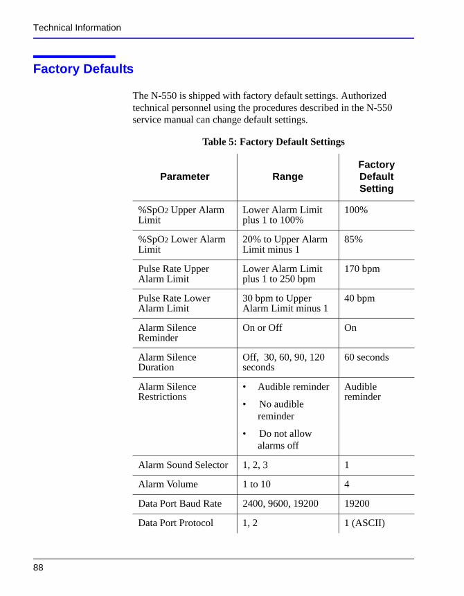
Technical Information
Factory Defaults
The N-550 is shipped with factory default settings. Authorized technical personnel using the procedures described in the N-550 service manual can change default settings.
Table 5: Factory Default Settings
Parameter RangeFactory Default Setting
%SpO2 Upper Alarm Limit
Lower Alarm Limit plus 1 to 100%
100%
%SpO2 Lower Alarm Limit
20% to Upper Alarm Limit minus 1
85%
Pulse Rate Upper Alarm Limit
Lower Alarm Limit plus 1 to 250 bpm
170 bpm
Pulse Rate Lower Alarm Limit
30 bpm to Upper Alarm Limit minus 1
40 bpm
Alarm Silence Reminder
On or Off On
Alarm Silence Duration
Off, 30, 60, 90, 120 seconds
60 seconds
Alarm Silence Restrictions
• Audible reminder
• No audible reminder
Audible reminder
88
• Do not allow alarms off
Alarm Sound Selector 1, 2, 3 1
Alarm Volume 1 to 10 4
Data Port Baud Rate 2400, 9600, 19200 19200
Data Port Protocol 1, 2 1 (ASCII)
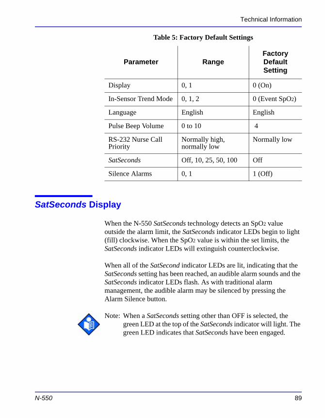
Technical Information
SatSeconds Display
When the N-550 SatSeconds technology detects an SpO2 value outside the alarm limit, the SatSeconds indicator LEDs begin to light (fill) clockwise. When the SpO2 value is within the set limits, the SatSeconds indicator LEDs will extinguish counterclockwise.
When all of the SatSecond indicator LEDs are lit, indicating that the SatSeconds setting has been reached, an audible alarm sounds and the SatSeconds indicator LEDs flash. As with traditional alarm management, the audible alarm may be silenced by pressing the
Display 0, 1 0 (On)
In-Sensor Trend Mode 0, 1, 2 0 (Event SpO2)
Language English English
Pulse Beep Volume 0 to 10 4
RS-232 Nurse Call Priority
Normally high, normally low
Normally low
SatSeconds Off, 10, 25, 50, 100 Off
Silence Alarms 0, 1 1 (Off)
Table 5: Factory Default Settings
Parameter RangeFactory Default Setting
N-550 89
Alarm Silence button.
Note: When a SatSeconds setting other than OFF is selected, the green LED at the top of the SatSeconds indicator will light. The green LED indicates that SatSeconds have been engaged.
Technical Information
Describing SatSeconds
With traditional alarm management, upper and lower alarm limits are set for monitoring oxygen saturation. During monitoring, as soon as an alarm limit is violated by as little as one percentage point, an audible alarm immediately sounds. When the %SpO2 level fluctuates near an alarm limit, the alarm sounds each time the limit is violated. Such frequent alarms can be distracting.
The N-550 utilizes Nellcor SatSeconds alarm management. With the SatSeconds technique, upper and lower alarm limits are set in the same way as traditional alarm management. However, the clinician also sets a SatSeconds limit that allows monitoring of %SpO2 below the selected lower alarm limit and above the selected upper alarm limit for a period of time before an audible alarm sounds.
The SatSeconds limit controls the time that the %SpO2 level may fall below the alarm limit before an audible alarm sounds.
The method of calculation is as follows:
The number of percentage points that the %SpO2 falls outside the alarm limit is multiplied by the number of seconds that the %SpO2 level remains outside that limit. This can be stated as an equation:
Points x Seconds = SatSeconds
Where:
Points = SpO2 percentage points outside of the limit
90
Seconds = number of seconds that SpO2 remains at that point outside of the limit
The alarm response time, assuming a SatSeconds limit set at 50 and a lower alarm limit set at 90, is described and illustrated below.
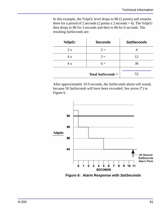
Technical Information
In this example, the %SpO2 level drops to 88 (2 points) and remains there for a period of 2 seconds (2 points x 2 seconds = 4). The %SpO2 then drops to 86 for 3 seconds and then to 84 for 6 seconds. The resulting SatSeconds are:
After approximately 10.9 seconds, the SatSeconds alarm will sound, because 50 SatSeconds will have been exceeded. See arrow (↑) in Figure 6.
%SpO2 Seconds SatSeconds
2 x 2 = 4
4 x 3 = 12
6 x 6 = 36
Total SatSeconds = 52
N-550 91
Figure 6: Alarm Response with SatSeconds
Technical Information
Saturation levels may fluctuate rather than remaining steady for a period of several seconds. Often, %SpO2 levels may fluctuate above and below the alarm limit, reentering the non-alarm range several times.
During such fluctuation, the N-550 integrates the number of %SpO2 points, both positive and negative, until either the SatSeconds limit (SatSeconds setting) is reached, or the %SpO2 level returns within a normal range and remains there.
SatSeconds “Safety Net”
The SatSeconds “Safety Net” is for patients whose saturation levels frequently go below the limit but do not stay below the limit long enough for the SatSeconds setting to be reached. When 3 or more limit violations occur in 60 seconds, an alarm will sound even if the SatSeconds setting has not been reached.
92
P r i n c i p l e s o f O p e r a t i o n
Oximetry Overview
The N-550 uses pulse oximetry to measure functional oxygen saturation in the blood. Pulse oximetry works by applying a sensor to a pulsating arteriolar vascular bed, such as a finger or toe. The sensor contains a dual light source and a photo detector.
Bone, tissue, pigmentation, and venous vessels normally absorb a constant amount of light over time. The arteriolar bed normally pulsates and absorbs variable amounts of light during the pulsations. The ratio of light absorbed is translated into a measurement of functional oxygen saturation (SpO2).
Because a measurement of SpO2 is dependent upon light from the sensor, excessive ambient light can interfere with this measurement.
Specific information about ambient conditions, sensor application, and patient conditions is contained throughout this manual.
Pulse oximetry is based on two principles: that oxyhemoglobin and deoxyhemoglobin differ in their absorption of red and infrared light (spectrophotometry), and that the volume of arterial blood in tissue (and hence, light absorption by that blood) changes during the pulse (plethysmography). A pulse oximeter determines SpO2 by passing red and infrared light into an arteriolar bed and measuring changes in
N-550 93
light absorption during the pulsatile cycle. Red and infrared low-voltage light-emitting diodes (LED) in the oximetry sensor serve as light sources; a photo diode serves as the photo detector.
Because oxyhemoglobin and deoxyhemoglobin differ in light absorption, the amount of red and infrared light absorbed by blood is related to hemoglobin oxygen saturation. To identify the oxygen saturation of arterial hemoglobin, the N-550 uses the pulsatile nature of arterial flow. During systole, a new pulse of arterial blood enters the vascular bed, and blood volume and light absorption increase.
Principles of Operation
During diastole, blood volume and light absorption reach their lowest point. The N-550 bases its SpO2 measurements on the difference between maximum and minimum absorption (measurements at systole and diastole). By doing so, it focuses on light absorption by pulsatile arterial blood, eliminating the effects of nonpulsatile absorbers such as tissue, bone, and venous blood.
There are various matrixes within the OXIMAX algorithm. Some are used to assess the severity of conditions presented to the N-550 in measuring SpO2 and pulse rate. These individual matrixes or combinations of these matrixes are used to drive the LED indicators on the N-550 front panel.
During challenging measurement conditions, which could be caused by low perfusion, motion, external interference, like ambient light, or a combination of these, the OXIMAX algorithm automatically extends the amount of data required for measuring SpO2 and pulse rate. If the resulting dynamic averaging time exceeds 20 seconds, the pulse search indicator is lit solid and SpO2 and pulse rate will continue to be updated every second. As these conditions become even more challenging, the amount of data required continues to extend. If the dynamic averaging time reaches 40 seconds, the pulse search indicator begins flashing, the SpO2 and pulse rate displays flash zero indicating a loss-of-pulse condition.
Automatic Calibration
Because light absorption by hemoglobin is wavelength dependent and because the mean wavelength of LEDs varies, an oximeter must
94
know the mean wavelength of the sensor's red LED to accurately measure SpO2.
During monitoring, the N-550's software selects coefficients that are appropriate for the wavelength of that individual sensor's red LED; these coefficients are then used to determine SpO2.
Additionally, to compensate for differences in tissue thickness, the light intensity of the sensor's LEDs is adjusted automatically.
Principles of Operation
Functional versus Fractional Saturation
This N-550 measures functional saturation -- oxygenated hemoglobin expressed as a percentage of the hemoglobin that can transport oxygen. It does not detect significant amounts of dysfunctional hemoglobin, such as carboxyhemoglobin or methemoglobin. In contrast, hemoximeters such as the IL482 report fractional saturation -- oxygenated hemoglobin expressed as a percentage of all measured hemoglobin, including measured dysfunctional hemoglobins. To compare functional saturation measurements to those from an instrument that measures fractional saturation, fractional measurements must be converted as follows:
Measured versus Calculated Saturation
When saturation is calculated from a blood gas partial pressure of oxygen (PO2), the calculated value may differ from the SpO2 measurement of a pulse oximeter. This usually occurs because the calculated saturation was not appropriately corrected for the effects of variables that shift the relationship between PO2 and pH, temperature, the partial pressure of carbon dioxide (PCO2), 2,3-DPG, and fetal hemoglobin. See Figure 7 on page 96.
functional saturation = fractional saturation
100 - (% carboxyhemoglobin + % methemoglobin)x100
N-550 95
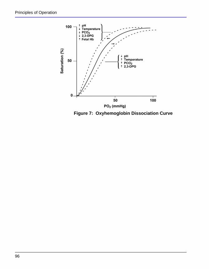
Principles of Operation
Figure 7: Oxyhemoglobin Dissociation Curve
96
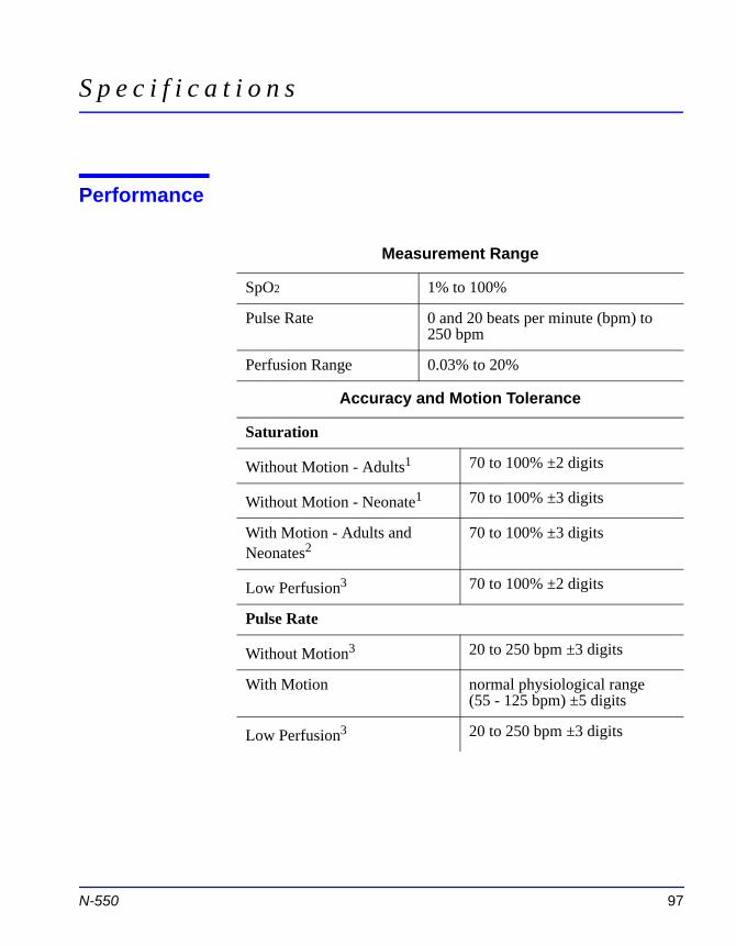
S p e c i f i c a t i o n s
Performance
Measurement Range
SpO2 1% to 100%
Pulse Rate 0 and 20 beats per minute (bpm) to 250 bpm
Perfusion Range 0.03% to 20%
Accuracy and Motion Tolerance
Saturation
Without Motion - Adults1 70 to 100% ±2 digits
Without Motion - Neonate1 70 to 100% ±3 digits
With Motion - Adults and Neonates2
70 to 100% ±3 digits
Low Perfusion3 70 to 100% ±2 digits
Pulse Rate
Without Motion3 20 to 250 bpm ±3 digits
N-550 97
With Motion normal physiological range (55 - 125 bpm) ±5 digits
Low Perfusion3 20 to 250 bpm ±3 digits
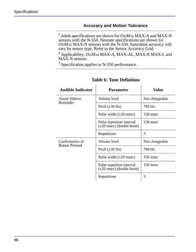
Specifications
1 Adult specifications are shown for OXIMAX MAX-A and MAX-N sensors with the N-550. Neonate specifications are shown for OXIMAX MAX-N sensors with the N-550. Saturation accuracy will vary by sensor type. Refer to the Sensor Accuracy Grid.2 Applicability: OXIMAX MAX-A, MAX-AL, MAX-P, MAX-I, and MAX-N sensors.3 Specification applies to N-550 performance.
Table 6: Tone Definition
Audible Indicator Parameter Value
Alarm Silence Reminder
Volume level Not changeable
Pitch (±30 Hz) 784 Hz
Pulse width (±20 msec) 150 msec
Pulse repetition interval (±20 msec) (double burst)
150 msec
Repetitions 3
Confirmation of Button Pressed
Volume level Not changeable
Pitch (±30 Hz) 784 Hz
Pulse width (±20 msec) 150 msec
Pulse repetition interval (±20 msec) (double burst)
150 msec
Repetitions 3
Accuracy and Motion Tolerance
98
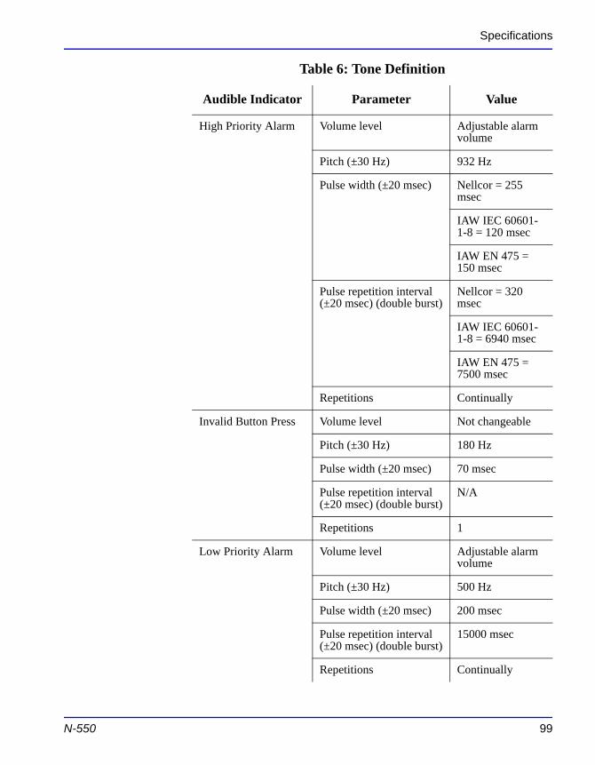
Specifications
High Priority Alarm Volume level Adjustable alarm volume
Pitch (±30 Hz) 932 Hz
Pulse width (±20 msec) Nellcor = 255 msec
IAW IEC 60601-1-8 = 120 msec
IAW EN 475 = 150 msec
Pulse repetition interval (±20 msec) (double burst)
Nellcor = 320 msec
IAW IEC 60601-1-8 = 6940 msec
IAW EN 475 = 7500 msec
Repetitions Continually
Invalid Button Press Volume level Not changeable
Pitch (±30 Hz) 180 Hz
Pulse width (±20 msec) 70 msec
Pulse repetition interval (±20 msec) (double burst)
N/A
Repetitions 1
Table 6: Tone Definition
Audible Indicator Parameter Value
N-550 99
Low Priority Alarm Volume level Adjustable alarm volume
Pitch (±30 Hz) 500 Hz
Pulse width (±20 msec) 200 msec
Pulse repetition interval (±20 msec) (double burst)
15000 msec
Repetitions Continually
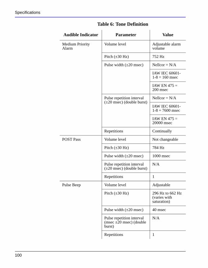
Specifications
Medium Priority Alarm
Volume level Adjustable alarm volume
Pitch (±30 Hz) 752 Hz
Pulse width (±20 msec) Nellcor = N/A
IAW IEC 60601-1-8 = 160 msec
IAW EN 475 = 200 msec
Pulse repetition interval (±20 msec) (double burst)
Nellcor = N/A
IAW IEC 60601-1-8 = 7600 msec
IAW EN 475 = 20000 msec
Repetitions Continually
POST Pass Volume level Not changeable
Pitch (±30 Hz) 784 Hz
Pulse width (±20 msec) 1000 msec
Pulse repetition interval (±20 msec) (double burst)
N/A
Repetitions 1
Pulse Beep Volume level Adjustable
Table 6: Tone Definition
Audible Indicator Parameter Value
100
Pitch (±30 Hz) 296 Hz to 662 Hz (varies with saturation)
Pulse width (±20 msec) 40 msec
Pulse repetition interval (msec ±20 msec) (double burst)
N/A
Repetitions 1
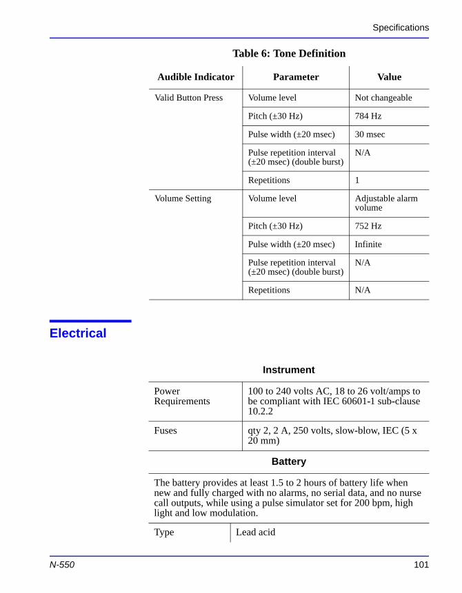
Specifications
Electrical
Valid Button Press Volume level Not changeable
Pitch (±30 Hz) 784 Hz
Pulse width (±20 msec) 30 msec
Pulse repetition interval (±20 msec) (double burst)
N/A
Repetitions 1
Volume Setting Volume level Adjustable alarm volume
Pitch (±30 Hz) 752 Hz
Pulse width (±20 msec) Infinite
Pulse repetition interval (±20 msec) (double burst)
N/A
Repetitions N/A
Table 6: Tone Definition
Audible Indicator Parameter Value
Instrument
Power Requirements
100 to 240 volts AC, 18 to 26 volt/amps to be compliant with IEC 60601-1 sub-clause 10.2.2
N-550 101
Fuses qty 2, 2 A, 250 volts, slow-blow, IEC (5 x 20 mm)
Battery
The battery provides at least 1.5 to 2 hours of battery life when new and fully charged with no alarms, no serial data, and no nurse call outputs, while using a pulse simulator set for 200 bpm, high light and low modulation.
Type Lead acid
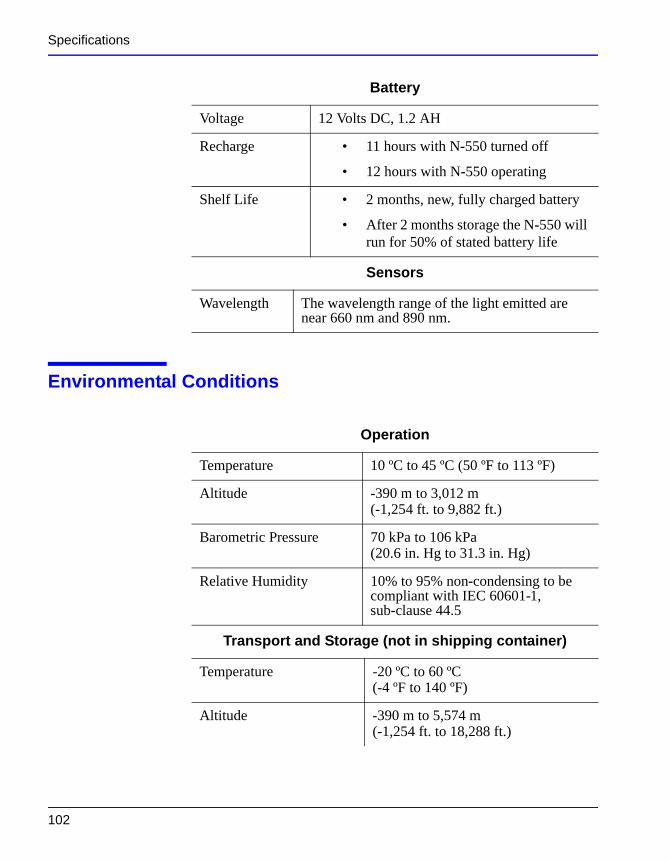
Specifications
Environmental Conditions
Voltage 12 Volts DC, 1.2 AH
Recharge • 11 hours with N-550 turned off
• 12 hours with N-550 operating
Shelf Life • 2 months, new, fully charged battery
• After 2 months storage the N-550 will run for 50% of stated battery life
Sensors
Wavelength The wavelength range of the light emitted are near 660 nm and 890 nm.
Battery
Operation
Temperature 10 ºC to 45 ºC (50 ºF to 113 ºF)
Altitude -390 m to 3,012 m(-1,254 ft. to 9,882 ft.)
Barometric Pressure 70 kPa to 106 kPa(20.6 in. Hg to 31.3 in. Hg)
Relative Humidity 10% to 95% non-condensing to be compliant with IEC 60601-1,
102
sub-clause 44.5
Transport and Storage (not in shipping container)
Temperature -20 ºC to 60 ºC (-4 ºF to 140 ºF)
Altitude -390 m to 5,574 m(-1,254 ft. to 18,288 ft.)
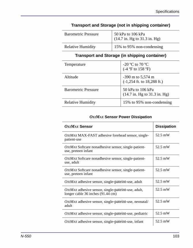
Specifications
Barometric Pressure 50 kPa to 106 kPa(14.7 in. Hg to 31.3 in. Hg)
Relative Humidity 15% to 95% non-condensing
Transport and Storage (in shipping container)
Temperature -20 ºC to 70 ºC (-4 ºF to 158 ºF)
Altitude -390 m to 5,574 m(-1,254 ft. to 18,288 ft.)
Barometric Pressure 50 kPa to 106 kPa(14.7 in. Hg to 31.3 in. Hg)
Relative Humidity 15% to 95% non-condensing
OXIMAX Sensor Power Dissipation
OXIMAX Sensor Dissipation
OXIMAX MAX-FAST adhesive forehead sensor, single-patient-use
52.5 mW
OXIMAX Softcare nonadhesive sensor, single-patient-use, preteen infant
52.5 mW
OXIMAX Softcare nonadhesive sensor, single-patient-use, adult
52.5 mW
OXIMAX Softcare nonadhesive sensor, single-patient-use, preteen infant
52.5 mW
Transport and Storage (not in shipping container)
N-550 103
OXIMAX adhesive sensor, single-pateint-use, adult 52.5 mW
OXIMAX adhesive sensor, single-pateint-use, adult, longer cable 36 inches (91.44 cm)
52.5 mW
OXIMAX adhesive sensor, single-pateint-use, neonatal/adult
52.5 mW
OXIMAX adhesive sensor, single-pateint-use, pediatric 52.5 mW
OXIMAX adhesive sensor, single-pateint-use, infant 52.5 mW
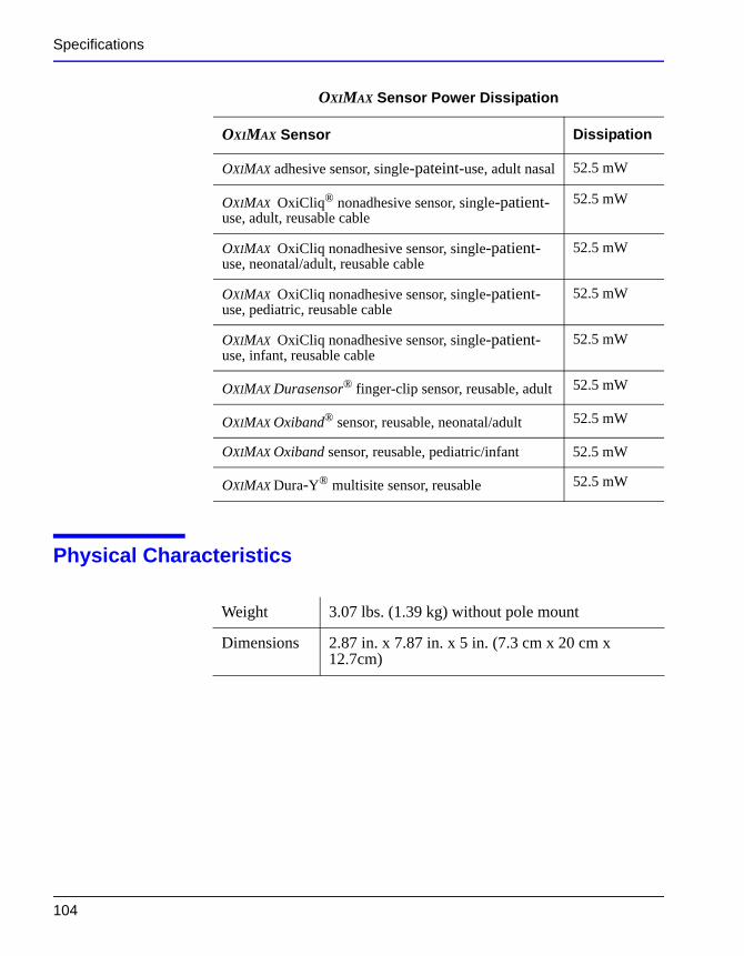
Specifications
Physical Characteristics
OXIMAX adhesive sensor, single-pateint-use, adult nasal 52.5 mW
OXIMAX OxiCliq® nonadhesive sensor, single-patient-use, adult, reusable cable
52.5 mW
OXIMAX OxiCliq nonadhesive sensor, single-patient-use, neonatal/adult, reusable cable
52.5 mW
OXIMAX OxiCliq nonadhesive sensor, single-patient-use, pediatric, reusable cable
52.5 mW
OXIMAX OxiCliq nonadhesive sensor, single-patient-use, infant, reusable cable
52.5 mW
OXIMAX Durasensor® finger-clip sensor, reusable, adult 52.5 mW
OXIMAX Oxiband® sensor, reusable, neonatal/adult 52.5 mW
OXIMAX Oxiband sensor, reusable, pediatric/infant 52.5 mW
OXIMAX Dura-Y® multisite sensor, reusable 52.5 mW
OXIMAX Sensor Power Dissipation
OXIMAX Sensor Dissipation
Weight 3.07 lbs. (1.39 kg) without pole mount
Dimensions 2.87 in. x 7.87 in. x 5 in. (7.3 cm x 20 cm x 12.7cm)
104
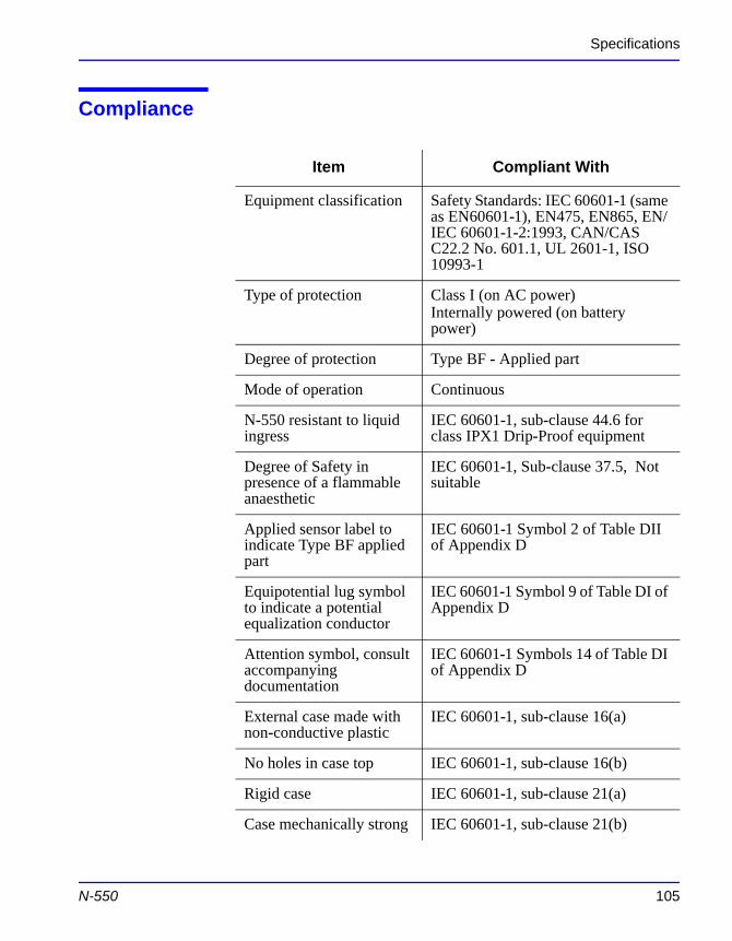
Specifications
Compliance
Item Compliant With
Equipment classification Safety Standards: IEC 60601-1 (same as EN60601-1), EN475, EN865, EN/IEC 60601-1-2:1993, CAN/CAS C22.2 No. 601.1, UL 2601-1, ISO 10993-1
Type of protection Class I (on AC power)Internally powered (on battery power)
Degree of protection Type BF - Applied part
Mode of operation Continuous
N-550 resistant to liquid ingress
IEC 60601-1, sub-clause 44.6 for class IPX1 Drip-Proof equipment
Degree of Safety in presence of a flammable anaesthetic
IEC 60601-1, Sub-clause 37.5, Not suitable
Applied sensor label to indicate Type BF applied part
IEC 60601-1 Symbol 2 of Table DII of Appendix D
Equipotential lug symbol to indicate a potential equalization conductor
IEC 60601-1 Symbol 9 of Table DI of Appendix D
Attention symbol, consult IEC 60601-1 Symbols 14 of Table DI
N-550 105
accompanying documentation
of Appendix D
External case made with non-conductive plastic
IEC 60601-1, sub-clause 16(a)
No holes in case top IEC 60601-1, sub-clause 16(b)
Rigid case IEC 60601-1, sub-clause 21(a)
Case mechanically strong IEC 60601-1, sub-clause 21(b)
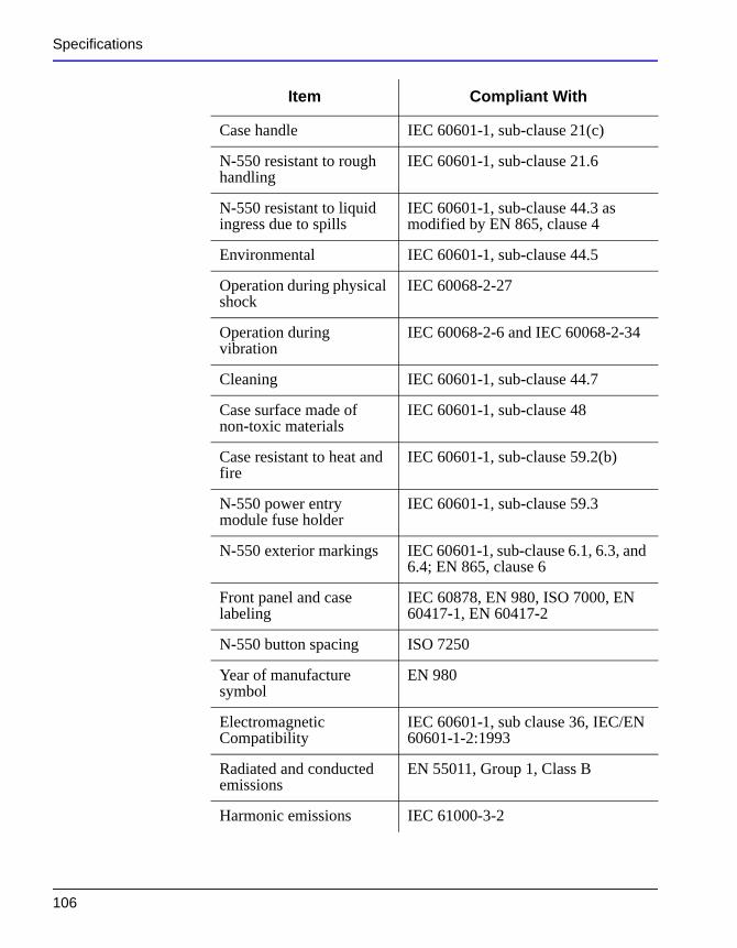
Specifications
Case handle IEC 60601-1, sub-clause 21(c)
N-550 resistant to rough handling
IEC 60601-1, sub-clause 21.6
N-550 resistant to liquid ingress due to spills
IEC 60601-1, sub-clause 44.3 as modified by EN 865, clause 4
Environmental IEC 60601-1, sub-clause 44.5
Operation during physical shock
IEC 60068-2-27
Operation during vibration
IEC 60068-2-6 and IEC 60068-2-34
Cleaning IEC 60601-1, sub-clause 44.7
Case surface made of non-toxic materials
IEC 60601-1, sub-clause 48
Case resistant to heat and fire
IEC 60601-1, sub-clause 59.2(b)
N-550 power entry module fuse holder
IEC 60601-1, sub-clause 59.3
N-550 exterior markings IEC 60601-1, sub-clause 6.1, 6.3, and 6.4; EN 865, clause 6
Front panel and case labeling
IEC 60878, EN 980, ISO 7000, EN 60417-1, EN 60417-2
N-550 button spacing ISO 7250
Item Compliant With
106
Year of manufacture symbol
EN 980
Electromagnetic Compatibility
IEC 60601-1, sub clause 36, IEC/EN 60601-1-2:1993
Radiated and conducted emissions
EN 55011, Group 1, Class B
Harmonic emissions IEC 61000-3-2
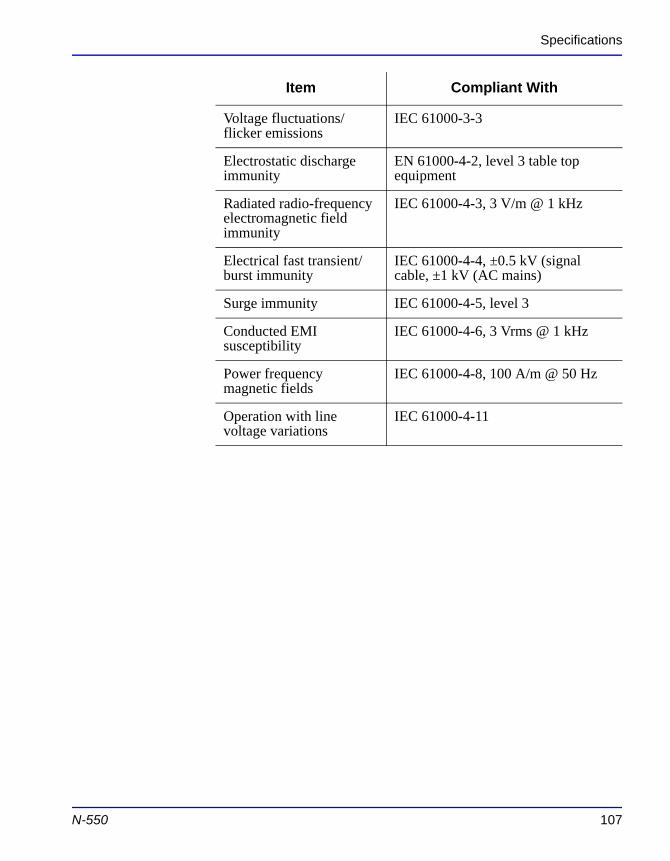
Specifications
Voltage fluctuations/flicker emissions
IEC 61000-3-3
Electrostatic discharge immunity
EN 61000-4-2, level 3 table top equipment
Radiated radio-frequency electromagnetic field immunity
IEC 61000-4-3, 3 V/m @ 1 kHz
Electrical fast transient/burst immunity
IEC 61000-4-4, ±0.5 kV (signal cable, ±1 kV (AC mains)
Surge immunity IEC 61000-4-5, level 3
Conducted EMI susceptibility
IEC 61000-4-6, 3 Vrms @ 1 kHz
Power frequency magnetic fields
IEC 61000-4-8, 100 A/m @ 50 Hz
Operation with line voltage variations
IEC 61000-4-11
Item Compliant With
N-550 107

Blank Page
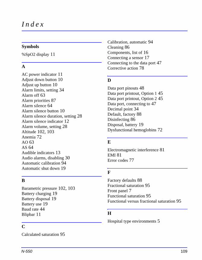
I n d e x
Symbols%SpO2 display 11
AAC power indicator 11Adjust down button 10Adjust up button 10Alarm limits, setting 34Alarm off 63Alarm priorities 87Alarm silence 64Alarm silence button 10Alarm silence duration, setting 28Alarm silence indicator 12Alarm volume, setting 28Altitude 102, 103Anemia 72AO 63AS 64Audible indicators 13Audio alarms, disabling 30Automatic calibration 94Automatic shut down 19
B
Calibration, automatic 94Cleaning 86Components, list of 16Connecting a sensor 17Connecting to the data port 47Corrective action 78
DData port pinouts 48Data port printout, Option 1 45Data port printout, Option 2 45Data port, connecting to 47Decimal point 34Default, factory 88Disinfecting 86Disposal, battery 19Dysfunctional hemoglobins 72
EElectromagnetic interference 81EMI 81Error codes 77
FFactory defaults 88
N-550 109
Barametric pressure 102, 103Battery charging 19Battery disposal 19Battery use 19Baud rate 44Blipbar 11
CCalculated saturation 95
Fractional saturation 95Front panel 7Functional saturation 95Functional versus fractional saturation 95
HHospital type environments 5
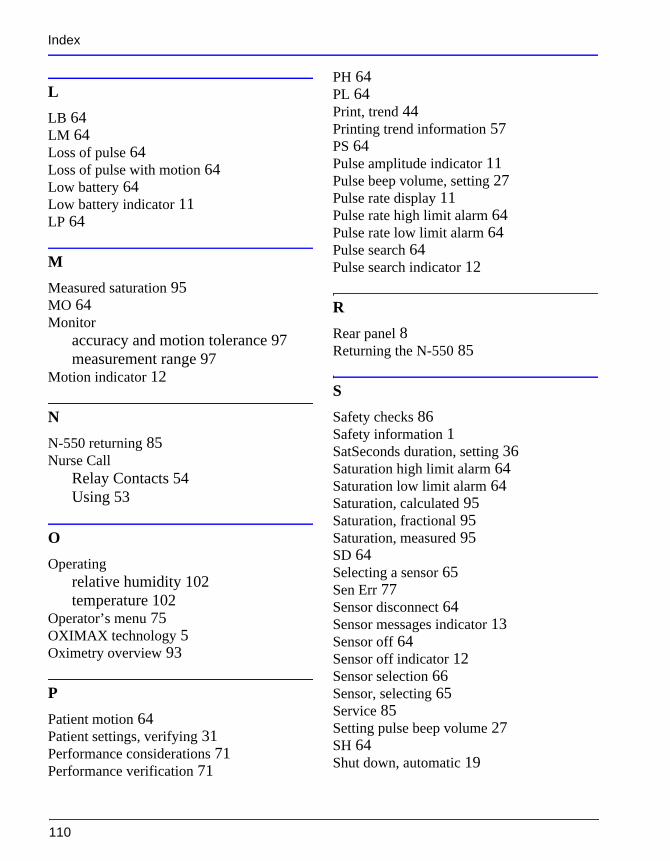
Index
LLB 64LM 64Loss of pulse 64Loss of pulse with motion 64Low battery 64Low battery indicator 11LP 64
MMeasured saturation 95MO 64Monitor
accuracy and motion tolerance 97measurement range 97
Motion indicator 12
NN-550 returning 85Nurse Call
Relay Contacts 54Using 53
OOperating
relative humidity 102temperature 102
PH 64PL 64Print, trend 44Printing trend information 57PS 64Pulse amplitude indicator 11Pulse beep volume, setting 27Pulse rate display 11Pulse rate high limit alarm 64Pulse rate low limit alarm 64Pulse search 64Pulse search indicator 12
RRear panel 8Returning the N-550 85
SSafety checks 86Safety information 1SatSeconds duration, setting 36Saturation high limit alarm 64Saturation low limit alarm 64Saturation, calculated 95Saturation, fractional 95Saturation, measured 95SD 64Selecting a sensor 65Sen Err 77
110
Operator’s menu 75OXIMAX technology 5Oximetry overview 93
PPatient motion 64Patient settings, verifying 31Performance considerations 71Performance verification 71
Sensor disconnect 64Sensor messages indicator 13Sensor off 64Sensor off indicator 12Sensor selection 66Sensor, selecting 65Service 85Setting pulse beep volume 27SH 64Shut down, automatic 19
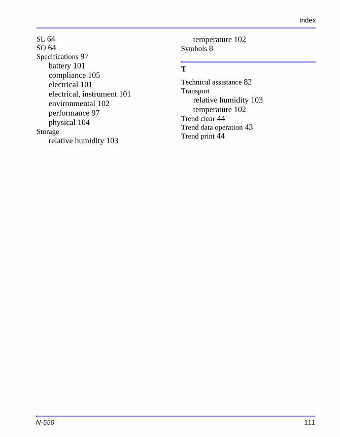
Index
SL 64SO 64Specifications 97
battery 101compliance 105electrical 101electrical, instrument 101environmental 102performance 97physical 104
Storagerelative humidity 103
temperature 102Symbols 8
TTechnical assistance 82Transport
relative humidity 103temperature 102
Trend clear 44Trend data operation 43Trend print 44
N-550 111

Blank Page

Blank Page
Tyco Healthcare Group LPNellcor Puritan Bennett Division4280 Hacienda DrivePleasanton, CA 94588 U.S.A.Telephone Toll Free 1.800.563.5267
Authorized RepresentativeTyco Healthcare UK LTD154 Fareham RoadGosport PO13 0AS, U.K.
© 2003 Nellcor Puritan Bennett Inc.All rights reserved
Rx ONLY
067856B-1103