Embed Size (px)
Citation preview
OWNER'S MANUALMODELNO.27149114.5HP38INCHLAWNTRACTOR
• Assembly
• Operation
Maintenance
• Service and Adjustments
• Troubleshooting
• Repair Parts
For Pads and Service, contact our authorized distributor.call 1-800-849-1297 For Technical Assistance: call 1-800-829-5886
182989 2.13.02 RDPRINTED IN U.S.A.
Safety Rules ......................................... 2Product Specifications .......................... 5AssemblylPre-Operation ...................... 7Operation ............................................ 10Maintenance Schedule ...................... 16
Maintenance ....................................... 16Service and Adjustments .................... 20Storage ............................................... 25Troubleshooting ................................. 26Repair Parts ........................................ 30Warranty ............................................. 46
IMPORTANT: This cutting machine is capable of amputating hands and .feet andthrowing objects. Failure to observe the following sarety instructions could result anserious injury or death.
I. GENERAL OPERATION• Read, understand, and follow all
instructionsin the manual and on themachine before starting.
• Only allow responsible adults, who arefamiliar with the instructions,to operatethe machine.
• Clear the area of objectssuch as rocks,toys, wire, etc., which could be picked upand thrown by the blade.
• Be sure the area is clear of other peoplebefore mowing. Stop machine if anyoneenters the area.
• Never carry passengers.• Do not mow in reverse unless absolutely
necessary. Always look down andbehind before and while backing.
• Be aware of the mower dischargedirectionand do not point it at anyone.Do not operate the mower without eitherthe entire grass catcher or the guard inplace.
• Slow down before turning.• Never leave a running machine unat-
tended. Always turn off blades, setparking brake, stop engine, and removekeys before dismounting.
• Turn off blades when not mowing.• Stop engine before removing grass
catcher or uncloggingchute.• Mow only in daylight or good artificial
light.• Do not operate the machine while under
the influence of alcohol or drugs.• Watch for traffic when operating near or
crossing roadways.• Use extra care when loading or unload-
ing the machine Into a trailer or truck.• Data indicatesthat operators, age 60
years and above, are involved in a largepercentage of dding mower-relatedinjuries. These operators shouldevaluate their ability to operate the ddingmower safely enough to protect them-selves and others from sedous injury.
• Keep machine free of grass, leaves orother debds build-up which can touchhot exhaust / engine parts and burn. Donot allow the mower deck to plow leave_or other debris which can cause build-up to occur. Clean any oil or fuelspillage before operating or storing themachine. Allow machine to cool beforestorage.
II, SLOPE OPERATION
Slopes are a major factor related to loss-of-control and tipover accidents, which canresult in severe injury or death. All slopesrequire extra caution. If you cannot back upthe slope or if you feel uneasy on it, do no1mow it.DO:
• Mow up and down slopes, not across.• Remove obstacles such as rocks, tree
limbs,etc.• Watch for holes, ruts,or bumps. Unever
terrain could overturn the machine. Tallgrass can hide obstacles.
• Use slow speed. Choose a low gear sothat you will not have to stop or shiftwhile on the slope.
• Follow the manufacturer's recommenda-tions for wheel weights or counter-weights to improve stabilk'y.
• Use extra care with grass catchers orother attachments. These can changethe stabilityof the machine.
• Keep all movement on the slopes slowand gradual. Do not make suddenchanges in speed or direction.
• Avoid startingor stoppingon a slope. Iftires losa traction, disengage the blade,€and proceed slowly straightdown theslope.
DO NOT:• Do not turn on slopes unless neces-
sary, and then, turn slowly and graduallydownhill, if possible.
2
• Do not mow near drop-offs,ditches, orembankments. The mower couldsuddenly turn over if a wheel is over theedge of a cliffor ditch, or if an edgecaves in.
• Do not mow on wet grass. Reducedtraction could cause sliding.
• Do not try to stabilize the machine byputtingyour foot on the ground.
• Do not use grass catcher on steepslopes.
IlL CHILDREN
Tragic accidents can occur if the operatoris not alert to the presence of children.Children are often attracted to themachine and the mowing activity. Neverassume that children will remain whereyou last saw them.• Keep children out of the mowing area
and under the watchful care of anotherresponsible adult.
• Be alert and turn machine off if childrenenter the area.
• Before and when backing, look behindand down for small children.
• Never carry children. They may fall offand be seriously injured or interferewith safe machine operation.
• Never allow children to operate themachine.
• Use extra care when approaching blindcorners, shrubs, trees, or other objectsthat may obscure vision.
IV. SERVICE
• Use extra care in handling gasolineand other fuels. They are flammableand vapors are explosive.
- Use only an approved container.- Never remove gas cap or add fuelwith the engine running. Allowengine to cool before refueling. Donot smoke.
-Never refuel the machine indoors.- Never store the machine or fuelcontainer inside where there is anopen flame, such as a water heater.
• Never run a machine inside a closedarea.
• Keep nuts and bolts, especially bladeattachment bolts, tight and keepequipment in good condition.
• Never tamper with safety devices.Check their proper operation regularly.
• Keep machine free of grass, leaves, orother debris build-up. Clean oil or fuelspillage. Allow machine to cool beforestoring.
• Stop and inspect the equipment if youstrike an object. Repair, if necessary,before restarting.
• Never make adjustments or repairswith the engine running.
• Grass catcher components are subjectto wear, damage, and deterioration,which could expose moving parts orallow objects to be thrown. Frequentlycheck components and replace withmanufacturer's recommended parts,when necessary.
• Mower blades are sharp and can cut.Wrap the blade(s) or wear gloves, anduse extra caution when servicing them.
• Check brake operation frequently.Adjust and service as required.
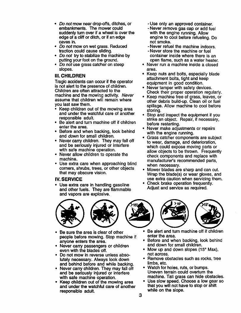
• Be sure the area is clear of other • Be alert and turn machine off if childrenpeople before mowing. Stop machine ifanyone enters the area.
• Never carry passengers or childreneven with the blades off.
• Do not mow in reverse unless abso-lutely necessary. Always look downand behind before and while backing.
• Never carry children. They may fall offand be seriously injured or interferewith safe machine operation.
• Keep children out of the mowing areaand under the watchful care of anotherresponsible adult.
3
enter the area.• Before and when backing, look behind
and down for small children.• Mow up and down slopes (15 o Max),
not across.• Remove obstacles such as rocks, tree
limbs, etc.• Watch for holes, ruts,or bumps.
Uneven terrain could overturn themachine. Tall grass can hide obstacles.
• Use slow speed. Choose a low gear sothat you will not have to stop or shiftwhile on the slope.
• Avoidstartingor stoppingon a slope.Iftires losetraction,disengagethebladesand proceedslowlystraightdownthe slope.
• If machine stops while going uphill,disengage blades, shift into reverseand back down slowly.
• Do not turn on slopes unless neces-sary, and then, turn slowly and gradu-ally downhill, if possible.
_Look for this symbol to point outimportant safety precautions. It meansCAUTION!!I BECOMEALERTll! YOURSAFETY IS INVOLVED.
CAUTION: In order to preventaccidental starting when setting up,transporting, adjusting or making repairs,always disconnect spark plug wire andplace wire where it cannot contact sparkplug.
CAUTION: Do not coast down a hillin neutral, you may lose control of thetractor.
CAUTION: Tow only the attachmentsthat are recommended by and complywith specifications of the manufacturer ofyour tractor. Use common sense whentowing. Operate only at the lowestpossible speed when on a slope. Tooheavy of a load, while on a slope, isdangerous. "13rescan lose tractionwiththe ground and cause you to lose controlof your tractor.
&WARNING: Engine exhaust, some ofits constituents, and certain vehiclecomponents contain or emit chemicalsknown to the State of Califomia to causecancer and birth defects or other repro-ductive harm.
WARNING: Battery posts, terminalsand related accessories contain lead andlead compounds, chemicals known to theState of California to cause cancer andbirth defects or other reproductive harm.Wash hands after handling.
4
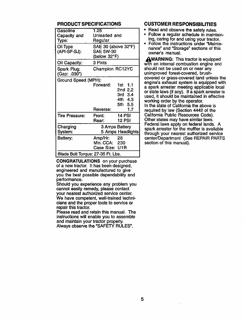
PRODUCT SPECIFICATIONS
Gasoline 1.25
Capacity and Unleaded andType: Regular
Oil Type SAE 30 (above 32°F)API-SF-SJ): SAE 5W-30
(below 32°F)
Oil Capacity: 3 Pints
Spark Plug: Champion RC12YC(Gap: .030")
Ground Speed (MPH):Forward: 1st 1.1
2nd 2.23rd 3.44th 4.35th 5.5
Reverse: 1.7
Tire Pressure: Front: 14 PSIRear: 12 PSI
Charging 3 Amps BatterySystem: 5 Amps Headlights
Battery: Amp/Hr: 28Min. CCA: 230Case Size: UIR
Blade Bolt Torque: 27-35 Ft. Lbs.
CONGRATULATIONS on your purchaseof a new tractor. It has been designed,engineered and manufactured to giveyou the best possible dependability andperformance.Should you experience any problem youcannot easily remedy, please contactyour nearest authorized service center.We have competent, well-trained techni-cians and the proper tools to service orrepair this tractor.Please read and retain this manual. Theinstructions will enable you to assembleand maintain your tractor properly.Always observe the =SAFETY RULES".
CUSTOMER RESPONSIBILITIES• Read and observe the safety rules.• Follow a regular schedule in maintain-
ing, caring for and using your tractor.• Follow the instructions under =Mainte-
nance _ and =Storage" sections of thisowner's manual.
,_I,WARNING: This tractor is equippedwith an internal combustion engine andshould not be used on or near anyunimproved forest-covered, brush-covered or grass-covered land unless theengine's exhaust system is equipped witha spark arrester meeting applicable localor state laws (if any). If a spark arrester isused, it should be maintained in effectiveworking order by the operator.In the state of California the above isrequired by law (Section 4442 of theCalifornia Public Resources Code).Other states may have similar laws.Federal laws apply on federal lands. Aspark arrester for the muffler is availablethrough your nearest authorized servicecenter/Deparfment (See REPAIR PARTSsection of this manual).
5
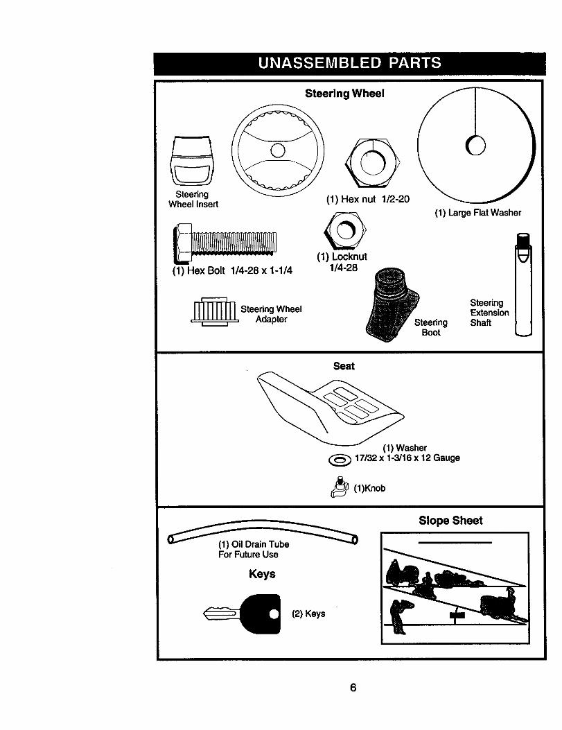
Steering Wheel
SteedngWheel Insert
(1) Hex Bolt 1/4-28 x 1-1/4
_L Steedng Wheel
Adapter
(1) Hex nut 1/2-20
(1) Locknut
1/4-28 _P_teedngBoot
(1) Large Flat Washer
SteeringExtensionShaft
Seat
(1) Washer
17/32 x 1-3/16 x 12 Gauge
_ (1)Knob
(__(1) Oil Drain Tub_
For Future Use
Keys
<__ (2) Keys
Slope Sheet
6
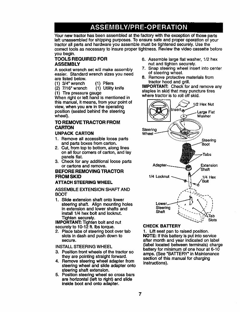
Your new tractor has been assembled at the factory with the exception of those partsleft unassembled for shipping purposes. To ensure safe and proper operation of yourtractor all parts and hardware you assemble must be tightened securely, Use thecorrect tools as necessary to insure proper tightness. Review the video cassette beforeyou begin.TOOLS REQUIRED FORASSEMBLY
A socket wrench set will make assemblyeasier. Standard wrench sizes you needare listed below.
(1) 3/4"wrench (1) Pliers(2) 7/16" wrench (1) Utility knife(1) Tire pressure gaugeWhen right or left hand is mentioned inthis manual, it means, from your point ofview, when you are in the operatingposition (seated behind the steeringwheel).
TO REMOVE TRACTOR FROMCARTONUNPACK CARTON
1. Remove all accessible loose partsand parts boxes from carton.
2. Cut, from top to bottom, along lineson all four corners of carton, and laypanels flat.
3. Check for any additional loose partsor cartons and remove.
BEFORE REMOVING TRACTORFROM SKID
ATrACH STEERING WHEEL
ASSEMBLE EXTENSION SHAFT ANDBOOT
1. Slide extension shaft onto lowersteering shaft. Align mounting holesin extension and lower shafts andinstall 1/4 hex bolt and Iocknut.Tighten securely.
IMPORTANT: Tighten bolt and nutsecurely to 10-12 ft. Ibs torque.2. Place tabs of steering boot over tab
slots in dash and push down tosecure.
INSTALL STEERING WHEEL3, Position front wheels of the tractor so
they are pointing straight forward.4. Remove steedng wheel adapter from
steedng wheel and slide adapter ontosteering shaft extension,
5. Position steering wheel so cross barsare horizontal (left to dght) and slideinside boot and onto adapter.
6. Assemble large flat washer, 1/2 hexnut and tighten securely.
7. Snap steering wheel insert into centerof steering wheel.
8. Remove protective materials fromtractor hood and grill.
IMPORTANT: Check for and remove anystaples in skid that may puncture tireswhere tractor is to roll off skid.
CHECK BATTERY
1. Lift seat pan to raised position.NOTE: If this battery is put into serviceafter month and year indicated on label(label located between terminals) chargebattery for minimum of one hour at 6-10amps. (See "BATTERY" in Maintenancesection of this manual for charginginstructions).
7
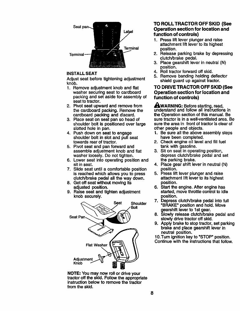
Seat
Terminal
INSTALL SEAT
Adjust seat before tightening adjustmentknob.1. Remove adjustment knob and fiat
washer securing seat to cardboardpacking and set aside for assembly ofseat to tractor.
2. Pivot seat upward and remove fromthe cardboard packing. Remove thecardboard packing and discard.
3. Place seat on seat pan so head ofshoulder bolt is positioned over largeslotted hole in pan.
4. Push down on seat to engageshoulder bolt in slot and pull seattowards rear of tractor.
5. Pivot seat and pan forward andassemble adjustment knob and flatwasher loosely. Do not tighten.
6. Lower seat into operating position andsit in seat.
7. Slide seat until a comfortable positionis reached which allows you to pressclutch/brake pedal all the way down.
8. Get off seat without moving itsadjusted position.
9. Raise seat and tighten adjustmentknob securely.
Seat Shoulder
Seat Pan-.
Flat Washer
TO ROLLTRACTOR OFF SKID (SeeOperation section for location andfunction of controls)1. Press lift lever plunger and raise
attachment lift lever to its highestposition.
2. Release parking brake by depressingclutch/brake pedal.
3. Place gearshift lever in neutral (N)position.
4, Roll tractor forward off skid.5. Remove banding holding deflector
shield guard up against tractor,
TO DRIVE TRACTOR OFF SKID (SeeOperation section for location andfunction of controls)
_WARNING: Before starting, read,understand and follow all instructions inthe Operation section of this manual. Besure tractor is in a well-ventilated area. Besure the area in front of tractor is clear ofother people and objects.1. Be sure all the above assembly steps
have been completed.2. Check engine oil level and fill fuel
tank with gasoline.3. Sit on seat in operating position,
depress clutch/brake pedal and setthe parking brake.
4. Place gear shift lever in neutral (N)position.
5. Press lift lever plunger and raiseattachment lift lever to its highestposition.
6. Start the engine, After engine hasstarted, move throttle control to idleposition.
7. Depress clutch/brake pedal into full'BRAKE" position and hold. Movegearshift lever to 1st gear.
8. Slowly release clutch/brake pedal andslowly drive tractor off skid.
9. Apply brake to stop tractor, set parkingbrake and place gearshift lever inneutral position.
10.Tum ignition key to "STOP" position.Continue with the instructions that follow.
AdjustmentKnob
NOTE: You may now roll or drive yourtractor off the skid. Follow the appropriateinstructionbelow to remove the tractorfrom the skid.
8
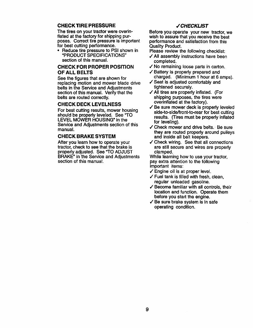
CHECK TIRE PRESSURE
The tiros on your tractor were overin-flated at the factory for shipping pur-poses. Correct tire pressure is importantfor best cutting performance.* Reduce tire pressure to PSI shown in
=PRODUCT SPECIFICATIONS"section of this manual.
CHECK FOR PROPER POSITIONOF ALL BELTS
See the figures that are shown forreplacing motion and mower blade drivebelts in the Service and Adjustmentssection of this manual. Verify that thebelts are routed correctly.
CHECK DECKLEVELNESS
For best cutting results, mower housingshould be properly leveled. See "TOLEVEL MOWER HOUSING" in theService and Adjustments section of thismanual.
CHECK BRAKE SYSTEM
After you learn how to operate yourtractor, check to see that the brake isproperly adjusted. See "TO ADJUSTBRAKE" in the Service and Adjustmentssection of this manual.
/CHECKLIST
Before you operate your new tractor, wewish to assure that you receive the bestperformance and satisfaction from thisQuality Product.Please review the following checklist:,/All assembly instructionshave been
completed.•/ No remaining loose parts in carton.,/Battery is properly prepared and
charged. (Minimum 1 hour at 6 amps).•/Seat is adjusted comfortably and
tightened securely.,/All tires are properly inflated. (For
shipping purposes, the tires wereoverinflated at the factory).
4"Be sure mower deck is properly leveledside-to-side/front-to-rear for best cuttingresults. (Tires must be properly inflatedfor leveling).
,/Check mower and drive belts. Be surethey are routed properly around pulleysand inside all belt keepers.
,/Check wiring. See that all connectionsare still secure and wires are properlyclamped.
While learning how to use your tractor,pay extra attention to the followingimportant items:,/Engine oil is at proper level.,/Fuel tank is filled with fresh, clean,
regular unleaded gasoline./ Become familiar with all controls, their
location and function. Operate thembefore you start the engine.
,/Be sure brake system is in safeoperating condition.
9

These symbols may appear on your tractor or in literature supplied with the product.Learn and understand their meaning.
BA'(-rERY CAUTION OR REVERSE FORWARD FAST SLOWWARNING
j oi kENG,.EONENG,NEOFFO,'PRESSUREUGHTSO.OV_,_T_.P
FUEL CHOKE MOWER HEIGHT PARKING BRAKE UNLOCKED MOWER LIFTLOCKED
R N H LA'rrACHMENT REVERSE NEUTRAL HIGH LOW PARKING BRAKE
CLUTCH ENGAGED
ATTACHMENT KEEP AREA CLEAR SLOPE HAZARDS
IGNmON CLUTCH DISENGAGED (SEE SAFETY RULES SECTION)
DANGER, KEEP HANDS AND FEET AWAY
10
FREE WHEEL(Automatic Models only)
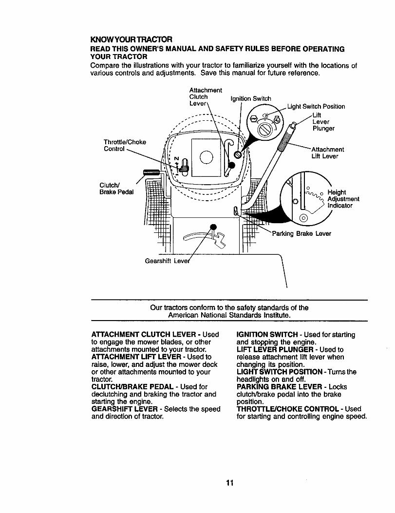
KNOWYOUR TRACTOR
READ THIS OWNER'S MANUAL AND SAFETY RULES BEFORE OPERATINGYOUR TRACTOR
Compare the illustrations with your tractor to familiarize yourself with the locations ofvarious controls and adjustments, Save this manual for future reference.
Throttle/Choke
Attachment
Clutch IgnitionSwitchLever
..... LeverPlunger
AttachmentLift Lever
Clutch/Brake Pedal Height
AdjustmentIndicator
Brake Lever
Gearshift
Our tractors conform to the safetystandards of theAmerican National Standards Institute.
ATTACHMENT CLUTCH LEVER - Usedto engage the mower blades, or otherattachments mounted to your tractor.ATTACHMENT LIFT LEVER - Used to
raise, lower, and adjust the mower deckor other attachments mounted to yourtractor.CLUTCH/BRAKE PEDAL - Used fordeclutching and braking the tractor andstarting the engine.GEARSHIFT LEVER - Selects the speedand direction of tractor.
IGNITION SWITCH - Used for startingand stopping the engine.LIFT LEVER PLUNGER - Used torelease attachment lift lever whenchanging its position.LIGHT SWITCH POSITION - Turns theheadlights on and off.PARKING BRAKE LEVER - Locksclutch/brake pedal into the brakeposition.THRO'I'rLE/CHOKE CONTROL - Usedfor starting and controlling engine speed.
11
The operation of any tractor can result in foreign objects thrown into theeyes, which can result in severe eye damage. Always wear safetyglasses or eye shields while operating your tractor or performing anyadjustments or repairs. We recommend a wide vision safety mask overspectacles or standard safety glasses.
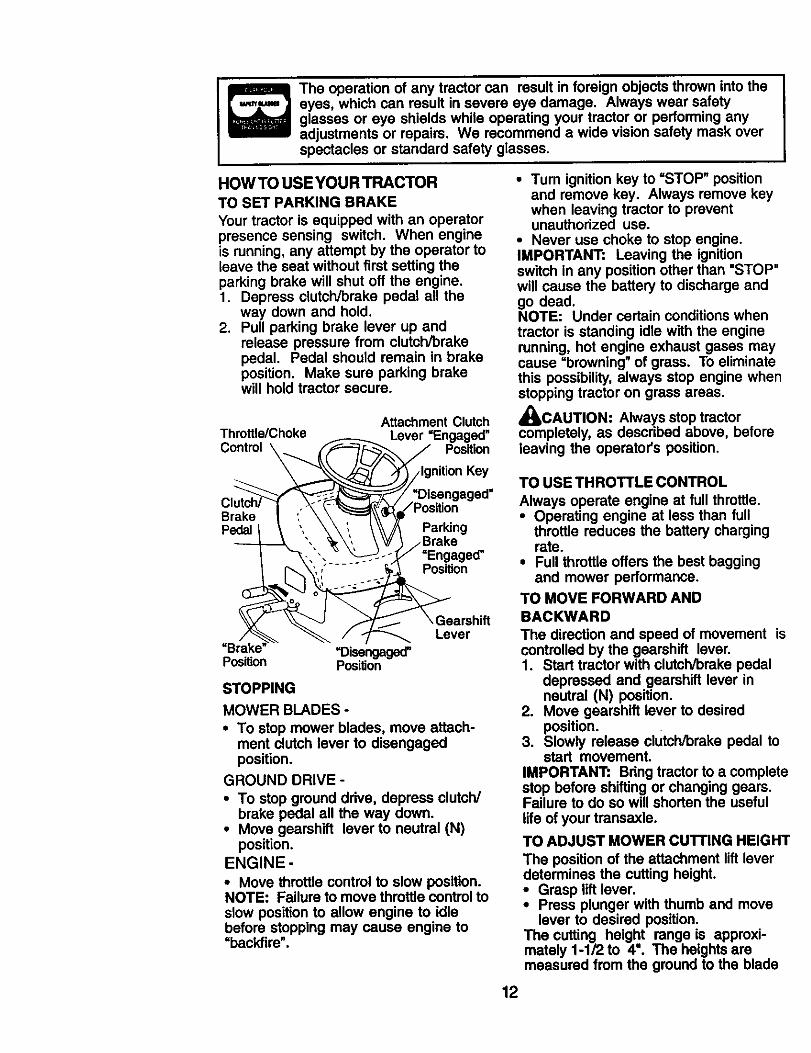
HOW TO USE YOUR TRACTORTO SET PARKING BRAKE
Your tractor is equipped with an operatorpresence sensing switch. When engineis running, any attempt by the operator toleave the seat without first setting theparking brake will shut off the engine.1. Depress clutch/brake pedal all the
way down and hold.2. Pull parking brake lever up and
release pressure from clutch/brakepedal. Pedal should remain in brakeposition. Make sure parking brakewill hold tractor secure.
Attachment ClutchThrottle/Choke Lever =Engaged"
Control\ _x__\__ _ Position\ "_/j::_-[ _/Ignition Key
__ ,_/=Disengagsd"
osit,onPedalt \ " \\:. \ _/A Parking
', _,, _ _/_ /Brake
._... v _ .,/,,/ =Engaged"
V _ \ Gearshift/ Lever
=Brake' =Disengaged"PosiUon Position
STOPPING
MOWER BLADES -
• To stop mower blades, move attach-ment clutch lever to disengagedposition.
GROUND DRIVE -
• To stop ground drive, depress clutch/brake pedal all the way down.
• Move gearshift lever to neutral (N)position.
ENGINE -
• Move throttle control to slow position.NOTE: Failure to move throttle control toslow position to allow engine to idlebefore stopping may cause engine to"backfire".
• Turn ignition key to =STOP" positionand remove key. Always remove keywhen leaving tractor to preventunauthorized use.
• Never use choke to stop engine.IMPORTANT: Leaving the ignitionswitch in any positionother than "STOP"will cause the battery to discharge andgo dead.NOTE: Under certain conditions whentractor is standing idle with the enginerunning, hot engine exhaust gases maycause =browning" of grass. To eliminatethis possibility,always stop engine whenstopping tractor on grass areas.
_CAUTION: Always stop tractorcompletely, as descdbed above, beforeleaving the operator's position.
TO USE THROTTLE CONTROL
Always operate engine at full throttle.• Operating engine at less than full
throttle reduces the battery chargingrate.
• Full throttle offers the best baggingand mower performance.
TO MOVE FORWARD ANDBACKWARD
The direction and speed of movement iscontrolled by the gearshift lever.1. Start tractor with clutch/brake pedal
depressed and gearshift lever inneutral (N) position.
2. Move gearshift lever to desiredposition.
3. Slowly release clutch/brake pedal tostart movement.
IMPORTANT: Bdng tractor to a completestop before shifting or changing gears.Failure to do so will shorten the usefullife of your transaxle.
TO ADJUST MOWER CuI-rlNG HEIGHT
The position of the attachment lift leverdetermines the cutting height.• Grasp lift lever.• Press plunger with thumb and move
lever to desired position,The cutting height range is approxi-mately 1-1/2 to 4". The heights aremeasured from the ground to the blade
12
tip with the engine not running. Theseheights are approximate and may varydepending upon soil conditions, height ofgrass and types of grass being mowed.• The average lawn should be cut to
approximately 2-1/2 inches during thecool season and to over 3 inchesduring hot months. For healthier andbetter looking lawns, mow often andafter moderate growth.
• For best cutting performance, grassover 6 inches in height should bemowed twice. Make the first cutrelatively high; the second to desiredheight.
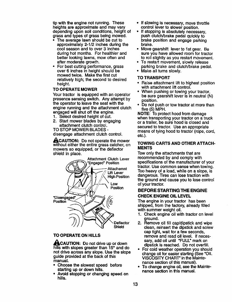
TO OPERATE MOWER
Your tractor is equipped with an operatorpresence sensing switch. Any attempt bythe operator to leave the seat with theengine running and the attachment clutchengaged will shut off the engine.1. Select desired height of cut.2. Start mower blades by engaging
attachment clutch control.TO STOP MOWER BLADES -disengage attachment clutch control.
_CAUTION: Do not operate the mowerwithout either the entire grass catcher, onmowers so equipped, or the deflectorshield in place.
__ Attachment Clutch Lever
_"_3 =Engaged" Position_._ _-f/_X / ----------Attachemnt_. _--_;R_.-'='_L=_- _.._,,'_' Lift Lever
"Disengaged'.. " I _,'_-_[/_
Position _ ,,,_
TO OPERATE ON HILLSA4_,CAUTION" Do not drive up or downhills with slopes greater than 15 ° and donot drive across any slope. Use the slopeguide provided at the back of thismanual.• Choose the slowest speed before
starting up or down hills.• Avoid stopping or changing speed on
hills.
• If slowing is necessary, move throttlecontrol lever to slower position.
• If stopping is absolutely necessary,push clutch/brake pedal quickly tobrake position and engage parkingbrake.
• Move gearshift lever to 1st gear. Besure you have allowed room for tractorto roll slightly as you restart movement.
• To restart movement, slowly releaseparking brake and clutch/brake pedal.
• Make all turns slowly.
TO TRANSPORT
• Raise attachment lift to highest positionwith attachment lift control.
• When pushing or towing your tractor,be sure gearshift lever is in neutral (N)position.
• Do not push or tow tractor at more thanfive (5) MPH.
NOTE: To protect hood from damagewhen transporting your tractor on a truckor a trailer, be sure hood is closed andsecured to tractor. Use an appropriatemeans of tying hood to tractor (rope, cord,etc.).
TOWING CARTS AND OTHER ATTACH-MENTS
Tow only the attachments that arerecommended by and comply withspecifications of the manufacturer of yourtractor. Use common sense when towing.Too heavy of a load, while on a slope, isdangerous. Tires can lose traction withthe ground and cause you to lose controlof your tractor.
BEFORE STARTING THE ENGINE
CHECK ENGINE OIL LEVEL
The engine in your tractor has beenshipped, from the factory, already filledwith summer weight oil.1. Check engine oil with tractor on level
ground.2. Remove oil fill cap/dipstick and wipe
clean, reinsert the dipstick and screwcap tight, wait for a few seconds,remove and read oil level. If neces-sary, add oil until "FULL" mark ondipstick is reached. Do not overfill.
• For cold weather operation you shouldchange oil for easier starting (See "OiLVISCOSITY CHART" in the Mainte-nance section of this manual).
• To change engine oil, see the Mainte-nance section in this manual.
13
ADD GASOLINE• Fill fuel tank to bottom of filler neck. Do
not overfill. Use fresh, clean, regularunleaded gasoline with a minimum of87 octane. (Use of leaded gasolinewill increase carbon and lead oxidedeposits and reduce valve life). Do notmix oil with gasoline. Purchase fuel inquantities that can be used within 30days to assure fuel freshness.
_,CAUTION: Wipe off any spilled oil orfuel. Do not store, spill or use gasolinenear an open flame.IMPORTANT: When operating intemperatures below32°F(0°C), use fresh,clean winter grade gasoline to helpinsure good cold weather starting.
_CAUTION: Alcohol blended fuels(called gasohol or using ethanol ormethanol) can attract moisture whichleads to separation and formation ofacids during storage. Acidic gas candamage the fuel system of an enginewhile in storage. To avoid engineproblems, the fuel system should beemptied before storage of 30 claysorlonger. Drain the gas tank, start theengine and let it run until the fuel linesand carburetor are empty. Use fresh fuelnext season. See Storage Instructionsforadditional information. Never use engineor carburetor cleaner products in the fueltank or permanent damage may occur.
TO START ENGINE
When starlingthe enginefor the firsttime orifthe enginehas runout of fuel,itwilltake extracrankingtime to move fuel fromthe tank tothe engine.1. Sit on seat in operating position,
depress clutch/brake pedal and setparking brake.
2. Place gear shift lever in neutral (N)position.
3. Move attachment clutch to disen-gaged position.
4. Move throttle control to choke position.NOTE: Beforestarting,read the warmandcold starlingproceduresbelow.5. Insert key into ignitionand turn key
clockwise to start position and releasekey as soon as engine starts. Do notrun starter continuouslyfor more thanfifteen seconds per minute. If theengine does not start after severalattempts, move throttle control to fastposition,wait a few minutes and tryagain. If engine still does not start,move the throttle control back to thechoke position and retry.
WARM WEATHER STARTING (50° Fandabove)6. When engine starts, move the throttle
control to the fast position.• The attachments and ground drive can
now be used. If the engine does notaccept the load, restart the engine andallow it to warm up for one minuteusing the choke as described above.
COLD WEATHER STARTING( 50° F andbelow)6. When engine starts, leave throttle
control in choke position until enginewarms up and begins to run roughly.Once rough running begins, immedi-ately move the throttle control to thefast position. Engine warm-up maytake from several seconds to severalminutes (the colder the temperature,the longer the warm-up).
• The attachments can also be usedduring the engine warm-up period.
NOTE: Ifat a highaltitude(above3000 feet)or in cold temperatures (below32 F) thecarburetorfuel mixturemay need to beadjustedfor best engineperformance (see_1"OADJUST CARBURETOR" inthe Serviceand Adjustmentssectionof this manual).
14
MOWING TIPS
• Tire chains cannot be used when themower housing is attached to tractor.
• Mower should be properly leveled forbest mowing performance. See "TOLEVEL MOWER HOUSING" in theService and Adjustments section ofthis manual.
• The left hand side of mower should beused for trimming.
• Drive so that clippings are dischargedonto the area that has already beencut. Have the cut area to the right ofthe tractor. This will result in a moreeven distribution of clippings and moreuniform cutting.
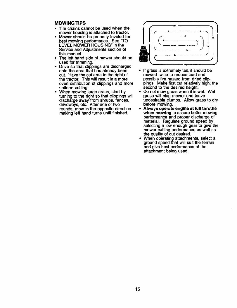
• When mowing large areas, start byturning to the right so that clippings willdischarge away from shrubs, fences,driveways, etc. After one or tworounds, mow in the opposite directionmaking left hand turns until finished.
• If grass is extremely tall, it should bemowed twice to reduce toad andpossible fire hazard from dried clip-pings. Make first cut relatively high; thesecond to the desired height.
• Do not mow grass when it is wet. Wetgrass will plug mower and leaveundesirable clumps. Allow grass to drybefore mowing.
• Always operate engine at full throttlewhen mowing to assure better mowingperformance and proper discharge ofmaterial. Regulate ground speed byselecting a low enough gear to give themower cutting performance as well asthe quality of cut desired.
• When operatingattachments, select aground speed that will suit the terrainand give best performance of theattachment being used.
15
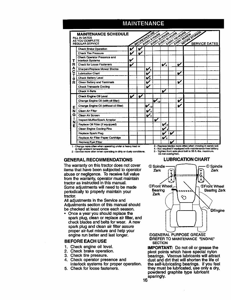
MAINTENANCE SCHEDULE ,,,_,,_-_ _ _,_ _
O..O.=..nCheck Tire Pressure 1
Check Operator Presence andT Interlock Systems
R Check for Loose Fasteners V / V's I_ /
A Sharpen/Replace Mower Blades I_s i
T Lubr_=k_Cha, JIv" I/i0 Check Battery Level
R Clean Battery and Termina_ _V' I_Check Transaxie Cooling
Check V-Belts
E Change Engine Oil (without oll ltlter) l_,_. li/
N Clea. Air Filter _1_./:G Clean Air Screen
i_ Inspect Muffler/Spark Attester I/
E Replace Oil Filter (If equipped) I1_.=
Clean Engine Cooling Rns I_=
Replace Spark Plug _/± I_Repta_eAir FilterPaper Car_dge
Replace Fuel Filter
1 - Chsnge more often when operating under a heavy load orin Idgh amb_nt temperatures.
2 - Sew_ce more often when operating in dirty or dusty conditions.
3 - Replace blades mo_eoften when mowing kl sandy soil,4 - Not required if equipped with maintenance-free battery.5 - 11ghlen front axle I_NOtboft to 35 ft,-Ib=, maximum.
Do not overtighten.
GENERAL RECOMMENDATIONS
The warranty on this tractor does not coveritems that have been subjected to operatorabuse or negligence. To receive full valuefrom the warranty, operator must maintaintractor as instructed in this manual.Some adjustments will need to be madeperiodically to propedy maintain yourtractor.All adjustments in the Service andAdjustments section of this manual shouldbe checked at least once each season.• Once a year you should replace the
spark plug, clean or replace air filter, andcheck blades and belts for wear. A newspark plug and clean air filter assureproper air-fuel mixture and help yourengine run better and last longer.
BEFORE EACH USE
1. Check engine oil level.2. Check brake operation.3. Check tire pressure.4. Check operator presence and
interlock systems for proper operation.5. Check for loose fasteners.
LUBRICATION CHART
@Spindle----Z-i__ _ _ (D Spindle
Zerkl ...T.T.=--===:===
@Front Wheel,- -; (_Froht WheelBearing ,_ :== : Bearing Zerk
Engeini,~._ _ .... i
(_ENERAL PURPOSE GREASE(2)REFER TO MAINTENANCE "ENGINE"
SECTION
IMPORTANT: DO not oil or grease thepivot points which have special nylonbearings. Viscous lubdcants will attractdust and dirt that will shorten the life ofthe self-lubricating bearings, if you feelthey must be lubdcatad, use only a dry.powdered graphite type lubdcant
16spadngly •
TRACTORAlways observe safety rules whenperforming any maintenance.BRAKE OPERATION
tf tractor requires more than six (6) feetstopping distance at high speed inhighest gear, then brake must be ad-justed. (See "TO ADJUST BRAKE" in theService and Adjustments section of thismanual).TIRES
• Maintain proper air pressure in all tires(See =PRODUCT SPECIFICATIONS"section of this manual).
• Keep tires free of gasoline, oil, or insectcontrol chemicals which can harmrubber.
• Avoid stumps, stones, deep ruts, sharpobjects and other hazards that maycause tire damage.
NOTE: To seal tire punctures and preventflat tires due to slow leaks, tire sealantmay be purchased from your local partsdealer. Tire sealant also prevents tire dryrot and corrosion.OPERATOR PRESENCE SYSTEM
Be sure operator presence and interlocksystems are working properly. If yourtractor does not function as described,repair the problem immediately.• The engine should not start unless the
brake pedal is fully depressed andattachement clutch control is in the
disengaged position.• When the engine is running, any
attempt by the operator to leave theseat without first setting the parkingbrake should shut off the engine.
• When the engine is running and theattachment clutch is engaged, anyattempt by the operator to leave theseat should shut off the engine.
• The attachment clutch should never
operate unless the operator is in theseat.
BLADE CARE
For best results mower blades must bekept sharp. Replace bent or damagedblades.
BLADE REMOVAL
I. Raise mower to highest position toallow access to blades.
2. Remove blade bolt, lock washer andfiat washer securing blade.
3. Install new or resharpened blade withtrailing edge up towards deck asshown.
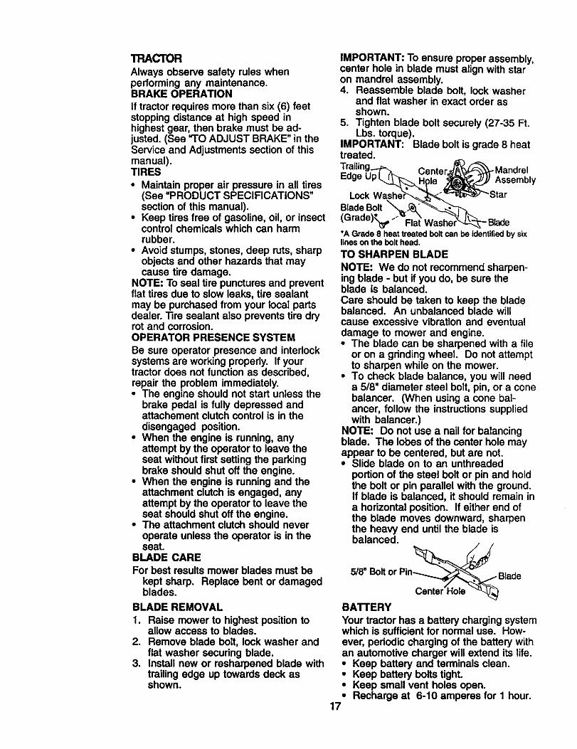
IMPORTANT: To ensure proper assembly,center hole in blade must align with staron mandrel assembly.4. Reassemble blade bolt, lock washer
and flat washer in exact order asshown.
5. Tighten blade bolt securely (27-35 Ft.Lbs. torque).
IMPORTANT: Blade bolt is grade 8 heattreated.
-MandrelEdge Assembly
LockBlade Bolt(Grade}Kt_'--" - Blade*A Grade 8 heat treated bolt can be identifiedby sixlines on the bolt head.
TO SHARPEN BLADE
NOTE: We do not recommend sharpen-ing blade - but if you do, be sure theblade is balanced.
Care should be taken to keep the bladebalanced. An unbalanced blade willcause excessive vibration and eventualdamage to mower and engine.• The blade can be sharpened with a file
or on a grinding wheel. Do not attemptto sharpen while on the mower.
• To check blade balance, you will needa 5/8" diameter steel bolt, pin, or a conebalancer. (When using a cone bal-ancer, follow the instructions suppliedwith balancer.)
NOTE: Do not use a nail for balancingblade. The lobes of the center hole mayappear to be centered, but are not.• Slide blade on to an unthreaded
portion of the steel belt or pin and holdthe bolt or pin parallel with the ground.If blade is balanced, it should remain ina hodzontal position. If either end ofthe blade moves downward, sharpenthe heavy end until the blade isbalanced.
/,f5/8" Bolt or Pin_j Blade
Center'Hola "_
BATTERY
Your tractor has a battery charging systemwhich is sufficient for normal use. How-ever, periodic charging of the battery withan automotive charger will extend its life.• Keep battery and terminals clean.• Keep battery bolts tight.• Keep small vent holes open.• Recharge at 6-10 amperes for I hour.
17
NOTE: The original equipment battery onyour tractor is maintenance free. Do notattempt to open or remove caps or covers.Adding or checking level of electrolyte isnot necessary.TO CLEAN BA'I-I'ERY AND TERMINALS
Corrosion and dirt on the battery andterminals can cause the battery to "leak"power.1. Disconnect BLACK battery cable first
then RED battery cable and removebattery from tractor.
2. Rinse the battery with plain water anddry.
3. Clean terminals and battery cableends with wire brush until bright.
4. Coat terminals with grease or petro-leum jelly.
5. Reinstall battery (See "REPLACINGBATTERY" in the SERVICE ANDADJUSTMENTS section of thismanual).
TRANSAXLE COOLING
Keep transaxle free from build-up of dirtand chaff which can restrict cooling.
V-BELTSCheck V-belts for deterioration and wearafter 100 hours of operation and replaceif necessary. The belts are not adjustable.Replace belts if they begin to slip fromwear.
ENGINELUBRICATION
Only use high quality detergent oil ratedwith API service classification SF-SJ.Select the oil's SAE viscosity gradeaccording to your expected operatingtemperature.
NOTE: Although multi-viscosityoils(5W30, 10W30 etc.) improve starting incold weather, these multi-viscosity oilswill result in increased oil consumptionwhen used above 32°F. Check yourengine oil level more frequently to avoidpossible engine damage from runninglow on oil.Change the oil after every 25 hours ofoperation or at least once a year if thetractor is not used for 25 hours In oneyear.
Check the crankcase oil level beforestarting the engine and after each eight(8) hours of operation. "tighten oil fill cap/dipstick securely each time you check theoil level.TO CHANGE ENGINE OIL
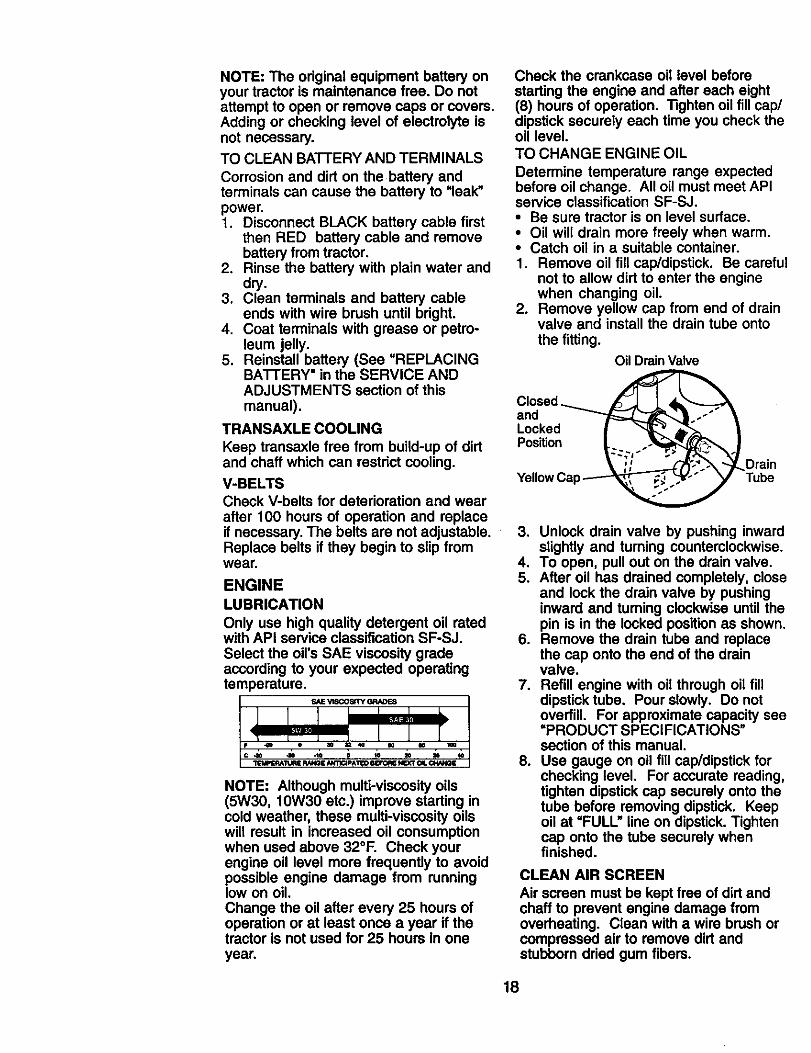
Determine temperature range expectedbefore oil change. All oil must meet APIservice classification SF-SJ.• Be sure tractor is on level surface.• Oil will drain more freely when warm.• Catch oil in a suitable container.1. Remove oil fill cap/dipstick. Be careful
not to allow dirt to enter the enginewhen changing oil.
2. Remove yellow cap from end of drainvalve and install the drain tube onto
the fitting.
Oil Drain Valve
Closed _
and __l_ .-"Locked I _ dl,_-._
Position__
Yellow Cap
lDrain
Tube
3. Unlock drain valve by pushing inwardslightly and turning counterclockwise.
4. To open, pull out on the drain valve.5. After oil has drained completely, close
and lock the drain valve by pushinginward and turning clockwise until thepin is in the locked positionas shown.
6. Remove the drain tube and replacethe cap onto the end of the drainvalve.
7. Refill engine with oil through oil filldipstick tube. Pour slowly. Do notoverfill. For approximate capacity see=PRODUCT SPECIFICATIONS"section of this manual.
8. Use gauge on oil fill cap/dipstick forchecking level. For accurate reading,tighten dipstick cap securely onto thetube before removing dipstick. Keepoil at "FULL" line on dipstick. Tightencap onto the tube securely whenfinished.
CLEAN AIR SCREEN
Air screen must be kept free of dirt andchaff to prevent engine damage fromoverheating. Clean with a wire brush orcompressed air to remove dirt andstubborn dried gum fibers.
18
AIR FILTER
Your engine will not run properly using adirty air filter. Clean the foam pre-cleanerafter every 25 hours of operation or everyseason. Service paper cartridge every100 hours of operation or every season,whichever occurs first.Service air cleaner more often underdusty conditions.1. Remove knob(s) and cover.TO SERVICE PRE-CLEANER2. Slide foam pre-cleaner off cartridge.3. Wash it in liquid detergent and water.4. Squeeze it dry in a clean cloth.5. Saturate it in engine oil. Wrap it in
clean, absorbent cloth and squeeze toremove excess oil.
NOTE: If very dirty or damaged, replacepre-cleaner.6. Reinstall pre-cleaner over cartridge.7. Reinstall cover and secure with
knob(s).TO SERVICE CARTRIDGE1. Remove cartridge nut.2. Carefully remove cartridge to prevent
debris from entering carburetor.Clean base carefully to prevent debrisfrom entering carburetor.
3. Clean cartridge by tapping gently onflat surface.
NOTE: if very dirty or damaged, replacecartridge.4. Reinstall cartridge, nut, precleaner,
cover and secure with knob(s).IMPORTANT" Petroleum solvents, suchas kerosene, are not to be used to cleanthe cartridge. They may cause deteriora-tion of the cartridge. Do not oil cartridge.Do net use pressurized air to clean or drycartddge.
KCOV.er..._:r--_ j Cover
nOD _J._Cartridge
"_JI_---"N ut
Foam Pre-_L- PaPerCleaner _ Cartridge
Bas_
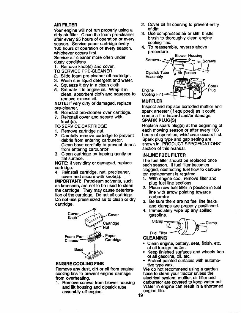
ENGINE COOLING FINS
Remove any dust, dirt or oil from enginecooling fins to prevent engine damagefrom overheating.1. Remove screws from blower housing
and lift housing and dipstick tubeassembly off engine.
2. Cover oil fill opening to prevent entryof dirt.
3. Use compressed air or stiff bristlebrush to thoroughly clean enginecooling fins.
4. To reassemble, reverse aboveprocedure.
Blower Housing
Screws'__ _S_rews_Dipstick Tube _ Air Scre-en "
Assembly. Spark
Engine _-AIP"_ Tz-_,_,j,f Plug
Cooling Fins _MUFFLER
Inspect and replace corroded muffler andspark arrester (if equipped) as it couldcreate a fire hazard and/or damage.SPARK PLUG(S)Replace spark plug(s) at the beginning ofeach mowing season or after every 100hours of operation, whichever occurs first.Spark plug type and gap setting areshown in "PRODUCT SPECIFICATIONS"section of this manual.
IN-LINE FUEL FILTER
The fuel filter should be replaced onceeach season. If fuel filter becomesclogged, obstructing fuel flow to carbure-tor, replacement is required.1. With engine cool, remove filter and
plug fuel line sections.2. Place new fuel filter in position in fuel
line with arrow pointing towardscarburetor.
3. Be sure there are no fuel line leaksand clamps are properly positioned.
4. Immediately wipe up any spilledgasoline.
CLEANING
i Clean engine, battery, seat, finish, etc.of all foreign matter.Keep finished surfaces and wheels freeof all gasoline, oil, etc.
• Protect painted surfaces with automo-tive type wax.
We do not recommend using a gardenhose to clean your tractor unless theelectdcal system, muffler, air filter andcarburetor are covered to keep water out.Water in engine can result in a shortenedengine life.
19
WARNING: TO AVlOD SERIOUS INJURY, BEFORE PERFORMING ANY
1. Depress clutch/brake pedal fully and set parking brake.2. Place gearshift lever in neutral (N) position.3. Place attachment clutch in =DISENGAGED" position.4. Turn ignition key to =STOP" and remove key.5. Make sure the blades and all moving parts have completely stopped.6. Disconnect spark plug wire from spark plug and place wire where it cannot
come in contact with plug.
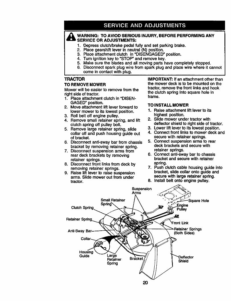
TRACTORTO REMOVE MOWERMower will be easier to remove from theright side of tractor.1. Place attachment clutch in =DISEN-
GAGED" position.2. Move attachment lift lever forward to
lower mower to its lowest position.3. Roll belt off engine pulley.4. Remove small retainer spring, and lift
clutch spring off pulley bolt.5. Remove large retainer spring, slide
collar off and push housing guide outof bracket.
6. Disconnect anti-sway bar from chassisbracket by removing retainer spring.
7. Disconnect suspension arms fromrear deck brackets by removingretainer springs.
8. Disconnect front links from deck byremoving retainer springs.
9. Raise lift lever to raise suspensionarms. Slide mower out from undertractor.
IMPORTANT: If an attachment other thanthe mower deck is to be mounted on thetractor, remove the front links and hookthe clutch spring Into square hole inframe.
TO INSTALL MOWER1. Raise attachment lift lever to its
highest position.2. Slide mower under tractor with
deflector shield to right side of tractor.3. Lower lift lever to its lowest position.4. Connect front links to mower deck and
secure with retainer springs.5. Connect suspension arms to rear
deck brackets and secure withretainer springs.
6. Connect anti-sway bar to chassisbracket and secure with retainerspring.
7. Push clutch cable housing guide intobracket, slide collar onto guide andsecure with large retainer spring.
8. Install belt onto engine pulley.
Clutch Spdng
Small Retainer
Spdng_
SuspensionArms
Pulley
Retainer S
Anti-Sway prings(Both Sides)
HousingGuide
RetainerSpring
Shield
2O
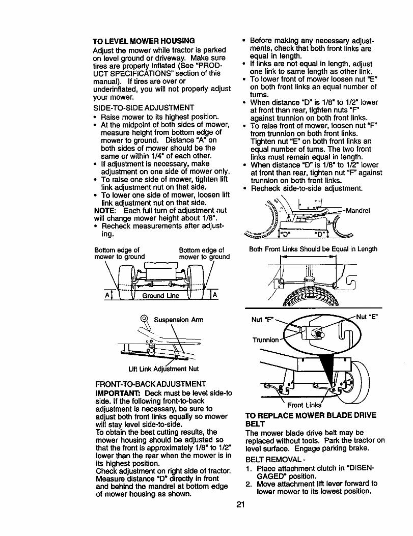
TO LEVEL MOWER HOUSING
Adjust the mower while tractor is parkedon level ground or driveway. Make suretires are properly inflated (See =PROD-UCT SPECIFICATIONS" section of thismanual). If tires are over orundednflated, you will not properly adjustyour mower.SIDE-TO-SIDE ADJUSTMENT
• Raise mower to its highest position.• At the midpoint of both sides of mower,
measure height from bottom edge ofmower to ground. Distance "A" onboth sides of mower should be thesame or within 1/4" of each other.
• If adjustment is necessary, makeadjustment on one side of mower only.
• To raise one side of mower, tighten liftlink adjustment nut on that side.
• To lower one side of mower, loosen liftlink adjustment nut on that side.
NOTE: Each full turn of adjustment nutwill change mower height about 1/8".• Recheck measurements after adjust-
ing.
Bottom edge of Bottom edge ofmower to ground mower to ground
• Before making any necessary adjust-ments, check that both front links areequal in length.
• If links are not equal in length, adjustone link to same length as other link.
• To lower front of mower loosen nut "E"on both front links an equal number ofturns.
• When distance =D" is 1/8" to 1/2" lowerat front than rear, tighten nuts "F"against trunnion on both front links.
• To raise front of mower, loosen nut "F"from trunnion on both front links.Tighten nut =E"on both front links anequal number of tums. The two frontlinks must remain equal in length.
• When distance =D" is 1/8" to 1/2=lowerat front than rear, tighten nut =F"againsttrunnion on both front links.
• Recheck side-to-side adjustment.
"D"
Both Front Unks Should be Equal in Length
Suspension Arm
FRONT-TO-BACK ADJUSTMENTIMPORTANT: Deck must be level side-toside. if the following front-to-backadjustment is necessary, be sure toadjust both front links equally so mowerwill stay level side-to-side.To obtain the best cutting results, themower housing should be adjusted sothat the front is approximately 1/8" to 112"lower than the rear when the mower is inits highest position.Check adjustment on right side of tractor.Measure distance =D_ directly in frontand behind the mandrel at bottom edgeof mower housing as shown.
:=E"
Front Links
TO REPLACE MOWER BLADE DRIVEBELT
The mower blade drive belt may bereplaced without tools. Park the tractor onlevel surface. Engage parking brake.
BELT REMOVAL-1. Place attachment clutch in =DISEN-
GAGED" position.2. Move attachment lift lever forward to
lower mower to its lowest position.
21
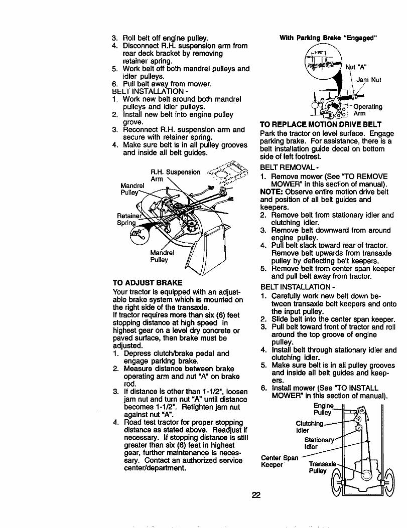
3. Roll belt off engine pulley.4. Disconnect R.H. suspension arm from
rear deck bracket by removingretainer spring.
5. Work belt off both mandrel pulleys andidler pulleys.
6. Pull belt away from mower.BELT INSTALLATION -1. Work new belt around both mandrel
pulleys and idler pulleys.2. Install new belt into engine pulley
grove.3. Reconnect R.H. suspension arm and
secure with retainer spring.4. Make sure belt is in all pulley grooves
and inside all belt guides.
R,H. SuspensionArm
Mandrel
Pulley
TO ADJUST BRAKE
Your tractor is equipped with an adjust-able brake system which is mounted onthe right side of the transaxle.If tractor requires more than six (6) feetstopping distance at high speed inhighest gear on a level dry concrete orpaved surface, then brake must beadjusted.I. Depress clutch/brake pedal and
engage parking brake.2. Measure distance between brake
operating arm and nut "A"on brakerod.
3. If distance is other than 1-1/2', loosenjam nut and turn nut =A" until distancebecomes 1-1/2". Retightan jam nutagainst nut =A".
4. Road test tractor for proper stoppingdistance as stated above. Readjust ifnecessary. If stopping distance is stillgreater than six (6) feet in highestgear, further maintenance is neces-sary. Contact an authorized servicecenter/department.
With Parking Brake "Engaged"
i_mt=A"
Nut
-OperatingArm
TO REPLACE MOTION DRIVE BELT
Park the tractor on level surface. Engageparking brake. For assistance, there is abelt installation guide decal on bottomside of left footrest.
BELT REMOVAL -
1. Remove mower (See "1"O REMOVEMOWER" in this section of manual).
NOTE: Observe entire motion drive beltand position of all belt guides andkeepers.2. Remove belt from stationary idler and
clutching idler.3. Remove belt downward from around
engine pulley.4. Pull belt slack toward rear of tractor.
Remove belt upwards from transaxlepulley by deflecting belt keepers.
5. Remove belt from center span keeperand pull belt away from tractor.
BELT INSTALLATION -
1. Carefully work new belt down be-tween transaxle belt keepers and ontothe input pulley.
2. Slide belt into the center span keeper.3. Pull belt toward front of tractor and roll
around the top groove of enginepulley.
4. Install belt through stationary idler andclutching idler.
5. Make sure belt is in all pulley groovesand inside all belt guides and keep-ers.
6. Install mower (See "TO INSTALLMOWER" in this section of manual).
Engine..__Pulley
Clutching_Idler
Stationary I"
IdlerFCenter SpanKeeper Transaxle._
Pulley _22
J
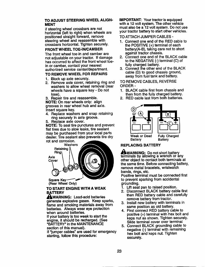
TO ADJUST STEERING WHEEL ALIGN-MENTif steering wheel crossbars are nothodzontal (left to right) when wheels arepositioned straight forward, removesteering wheel and reassemble withcrossbars horizontal. Tighten securely.FRONT WHEEL TOE-IN/CAMBERThe front wheel toe-in and camber arenot adjustable on your tractor. If damagehas occurred to affect the front wheel toe-in or camber, contact your nearestauthorized service center/department.TO REMOVE WHEEL FOR REPAIRS
1. Block up axle securely.2. Remove axle cover, retaining ring and
washers to allow wheel removal (rearwheels have a square key - Do notlose).
3. Repair tire and reassemble.NOTE: On rear wheels only: aligngrooves in rear wheel hub and axle.Insert square key.4. Replace washers and snap retaining
ring securely in axle groove.5. Replace axle cover.NOTE: To seal tire punctures and preventflat tires due to slow leaks, tire sealantmay be purchased from your local partsdealer. Tire sealant also prevents tire dryrot and corrosion.
WashersRetaining
AxleCover
Square Key _'"(Rear Wheel Only)
TO START ENGINE WITH A WEAK
_TTAE RYRNING: Lead-acid batteries
generate explosive gases. Keep sparks,flame and smoking materials away frombatteries. Always wear eye protectionwhen around batteries.If your battery is too weak to start theengine, it should be recharged. (See"BATTERY" in the MAINTENANCEsection of this manual).If =jumper cables" are used for emergencystarting, follow this procedure:
IMPORTANT: Your tractor is equippedwith a 12 volt system. The other vehiclemust also be a 12 volt system. Do not useyour tractor battery to start other vehicles.
TO A'I-FACH JUMPER CABLES -
1. Connect one end of the RED cable tothe POSITIVE (+) terminal of eachbattery(A-B), taking care not to shortagainst tractor chassis.
2. Connect one end of the BLACK cable
to the NEGATIVE (-) terminal (C) offully charged battery.
3. Connect the other end of the BLACKcable (D) to good chassis ground,away from fuel tank and battery.
TO REMOVE CABLES, REVERSEORDER -1. BLACK cable first from chassis and
then from the fully charged battery.2. RED cable last from both batteries.
B
Weak or Dead Fully ChargedBattery Battery
REPLACING BATTERY
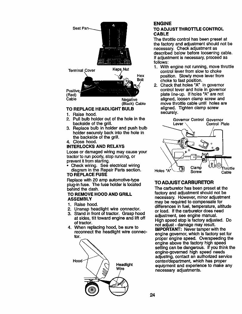
x't_WA,RN.ING: Do not short batteryterminals oy allowing a wrencn or anyother object to contact both terminals atthe same time. Before connecting battery,remove metal bracelets, wristwatchbands, dngs, etc.Positive terminal must be connected firstto prevent sparking from accidentalgrounding.1. Lift seat pan to raised position.2. Disconnect BLACK battery cable first
then RED battery cable and carefullyremove battery from tractor.
3. Install new battery with terminals insame position as old battery.
4. First connect RED battery cable topositive (+) terminal with hex bolt andkeps nut as shown. Tighten securely.Slide terminal cover over terminal
5. Connect BLACK grounding cable tonegative (-) terminal with remaininghex bolt and keps nut. Tightensecurely.
23
Terminal Nut
HexBolt
Positive(Red)Cable Negative
(Black) CableTO REPLACE HEADLIGHT BULB1. Raise hood.2. Pull bulb holder out of the hole in the
backside of the grill.3. Replace bulb in holder and push bulb
holder securely back into the hole inthe backside of the grill.
4. Close hood.INTERLOCKS AND RELAYS
Loose or damaged wiring may cause yourtractor to run poorly, stop running, orprevent it from starting.• Check wiring. See electrical wiring
diagram in the Repair Parts section.TO REPLACE FUSE
Replace with 20 amp automotive-typeplug-in fuse. The fuse holder is locatedbehind the dash.TO REMOVE HOOD AND GRILLASSEMBLY
1. Raise hood.2. Unsnap headlight wire connector.3. Stand in front of tractor. Grasp hood
at sides, tilt toward engine and lift offof tractor.
4. When replacing hood, be sure toreconnect the headlight wire connec-tor.
HeadlightWire
ENGINE
TO ADJUST THRO'I-I'LE CONTROLCABLE
The throttle control has been preset atthe factory and adjustment should not benecessary. Check adjustment asdescribed below before loosening cable.If adjustment is necessary, proceed asfollows:1. With engine not running, move throttle
control lever from slow to chokeposition. Slowly move lever fromchoke to fast position.
2. Check that holes =A" in governorcontrol lever and hole in governorplate line-up. If holes "A" are notaligned, loosen clamp screw andmove throttle cable until holes are
aligned. Tighten clamp screwsecurely.
Governor Control GovernorControl Plate
\
Holes Screw Cable
TO ADJUST CARBURETOR
The carburetor has been preset at thefactory and adjustment should not benecessary. However, minor adjustmentmay be required to compensate fordifferences in fuel, temperature, altitudeor load. If the carburetor does needadjustment, see engine manual.High speed stop is factory adjusted. Donot adjust - damage may result.IMPORTANT: Never tamper with theengine govemor, which is factory set forproper engine speed. Overspeeding theengine above the factory high speedsetting can be dangerous. If you think theengine-governed high speed needsadjusting, contact an authorized servicecenter/department, which has properequipment and experience to make anynecessary adjustments.
24
Immediately prepare your tractor forstorage at the end of the season or if thetractor will not be used for 30 days ormore.
_lb CAUTION: Never store the tractorwith gasoline in the tank inside a buildingwhere fumes may reach an open flame orspark. Allow the engine to cool beforestoring in any enclosure.
TRACTORRemove mower from tractor for winterstorage. When mower is to be stored fora period of time, clean it thoroughly,remove all dirt, grease, leaves, etc. Storein a clean, dry area.1. Clean entire tractor (See =CLEANING"
in the Maintenance section of thismanual).
2. Inspect and replace belts, if necessary(See belt replacement instructions inthe Service and Adjustments sectionof this manual).
3. Lubricate as shown in the Mainte-nance section of this manual.
4. Be sure that all nuts, bolts and screwsare securely fastened. Inspect movingparts for damage, breakage and wear.Replace if necessary.
5. Touch up all rusted or chipped paintsurfaces; sand lightly before painting.
BA'I'rERY
• Fully charge the battery for storage.• After a period of time in storage, battery
may require recharging.• To help prevent corrosion and power
leakage during long periods of storage,battery cables should be disconnectedand battery cleaned thoroughly (see=TO CLEAN BATTERY AND TERMI-NALS" in the Maintenance section ofthis manual).
• After cleaning, leave cables discon-nected and place cables where theycannot come in contact with batteryterminals.
• If battery is removed from tractor forstorage, do not store battery directly onconcrete or damp surfaces.
ENGINEFUEL SYSTEM
IMPORTANT: It is important to preventgum deposits from forming In essentialfuel system parts such as carburetor, fuelhose, or tank during storage. Also,
alcohol blended fuels (called gasohol orusing ethanol or methanol) can attractmoisture which leads to separation andformation of acids during storage. Acidicgas can damage the fuel system of anengine while in storage.1. Drain the fuel tank.2. Start the engine and let it run until the
fuel lines and carburetor are empty.• Never use engine or carburetor cleaner
products in the fuel tank or permanentdamage may occur.
• Use fresh fuel next season.NOTE: Fuel stabilizer is an acceptablealternative in minimizing the formation offuel gum deposits during storage. Addstabilizer to gasoline in fuel tank orstorage container. Always follow the mixratio found on stabilizer container. Runengine at least 10 minutes after addingstabilizer to allow the stabiUzer to reachthe carburetor. Do not drain the gas tankand carburetor if using fuel stabilizer.ENGINE OIL
Drain oil (with engine warm) and replacewith clean engine oil (See =ENGINE" inthe Maintenance section of this manual).CYLINDER(S)1. Remove spark plug(s).2. Pour one ounce of oil through spark
plug hole(s) into cylinder(s).3. Turn ignition key to start position for a
few seconds to distdbute oil.4. Replace with new spark plug(s).
OTHER
• Do not store gasoline from one seasonto another.
• Replace your gasoline can if your canstarts to rust. Rust and/or dirt in yourgasoline will cause problems.
• If possible, store your tractor indoorsand cover it to give protection from dustand dirt.
• Cover your tractor with a suitableprotective cover that does not retainmoisture. Do not use plastic. Plasticcannot breathe which allows conden-sation to form and will cause yourtractor to rust.
IMPORTANT: Never cover tractor whileengine and exhaust areas are still warm.
25
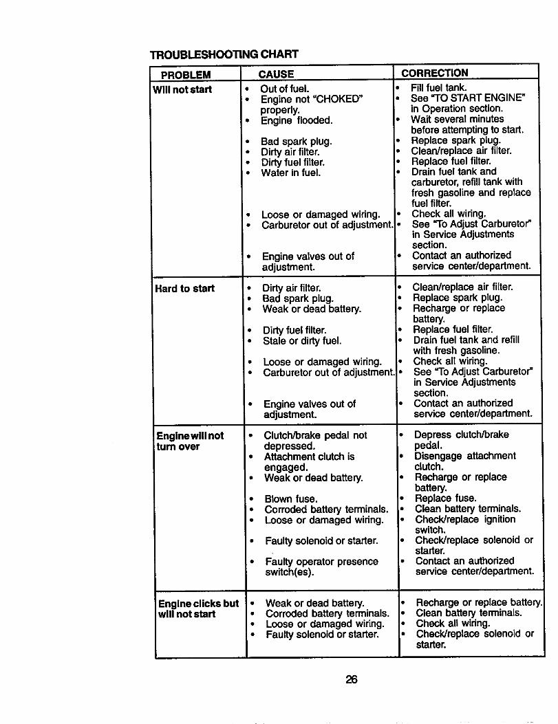
TROUBLESHOOTING CHART
PROBLEM CAUSE
Willn_stad
Hard to start
Enginewlll notturn over
Engine clicks butwill not start
• Out offuel.• Engine not "CHOKED" •
properl_• Engine flooded.
• Bad spark plug.• Dirty air filter.• Dirty fuel filter.• Water in fuel.
• Loose or damaged wiring. •• Carburetor out of adjustment •
Engine valves out ofadjustment.
• Dirty air filter.• Bad spark plug.• Weak or dead battery.
• Dirty fuel filter.• Stale or dirty fuel.
• Loose or damaged wiring.• Carburetor out of adjustment.
Engine valves out ofadjustment.
CORRECTION
Clutch/brake pedal not
Fill fuel tank.See "TO START ENGINE"in Operation section.Wait several minutesbefore attempting to start.Replace spark plug.Clean/replace air filter.Replace fuel filter.Drain fuel tank andcarburetor, refilltank withfresh gasoline and replacefuel filter.Check all wiring.See "To Adjust Carburetor"in Service Adjustmentssection.Contact an authorizedservice center/department.
• Clean/replace air filter.• Replace spark plug.• Recharge or replace
battery.• Replace fuel filter.• Drain fuel tank and refill
with fresh gasoline.• Check all wiring.• See "To Adjust Carburetor"
in Service Adjustmentssection.
• Contact an authorizedservice center/department.
Depress clutch/brakedepressed.
• Attachment clutch isengaged.
• Weak or dead battery,
• Blown fuse.
pedal.• Disengage attachment
clutch.• Recharge or replace
battery.• Replace fuse.
Corroded battery terminals.Loose or damaged wiring.
Faulty solenoid or starter,
Faulty operator presenceswitch(es).
• Weak or dead battery.• Corroded battery terminals.• Loose or damaged wiring.• Faulty solenoid or starter.
• Clean battery terminals.• Check/replace ignition
switch.• Check/replace solenoid or
starter.• Contact an authorized
service center/department.
• Recharge or replace battery• Clean battery terminals.• Check all widng.• Check/replace solenoid or
starter.
26
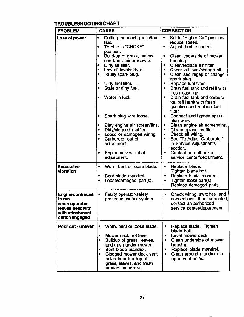
TROUBLESHOOTING CHART
CAUSE
• Cutting too much grass/toofast.
• Throttle in "CHOKE"position.
• Build-up of grass, leavesand trash under mower.
• Dirty air filter.• Low oil level/dirty oil.• Faulty spark plug.
PROBLEM
Lossofpower
• Dirty fuel filter.• Stale or dirty fuel.
• Water in fuel.
• Spark plug wire loose.
• Dirty engine air screen/fins.• Dirty/clogged muffler.• Loose or damaged wiring.• Carburetor out of
adjustment.
Excessivevibration
Engine continues •to runwhen operatorleaves seat withwith attachmentciutch engaged
Poor cut- uneven •
Engine valves out ofadjustment.
Worn, bent or loose blade.
Bent blade mandrel.Loose/damaged part(s).
Faulty operator-safetypresence control system.
Wom, bent or loose blade.
Mower deck not level.
Buildup of grass, leaves,and trash under mower.Bent blade mandrel.Clogged mower deck ventholes from buildup ofgrass, leaves, and trasharound mandrels.
CORRECTION
• Set in =Higher Cut" position/reduce speed.
• Adjust throttle control.
• Clean underside of mowerhousing.
• Clean/replace air filter.• Check oil level/change oil.• Clean and regap or change
spark plug.• Replace fuel filter.• Drain fuel tank and refill with
fresh gasoline.• Drain fuel tank and carbure-
tor, refill tank with freshgasoline and replace fuelfilter.
• Connect and tighten sparkplug wire.
• Clean engine air screen/fins.• Clean/replace muffler.• Check all wiring.• See "To Adjust Carburetor"
in Service Adjustmentssection.
• Contact an authorizedservice center/department.
• Replace blade.Tighten blade bolt.
• Replace blade mandrel.• Tighten loose part(s).
Replace damaged parts.
Check wiring, switches andconnections. If not correctedcontact an authorizedservice center/department.
• Replace blade. Tightenblade bolt.
• Level mower deck.• Clean underside of mower
housing.• Replace blade mandrel.• Clean around mandrels to
open vent holes.
27
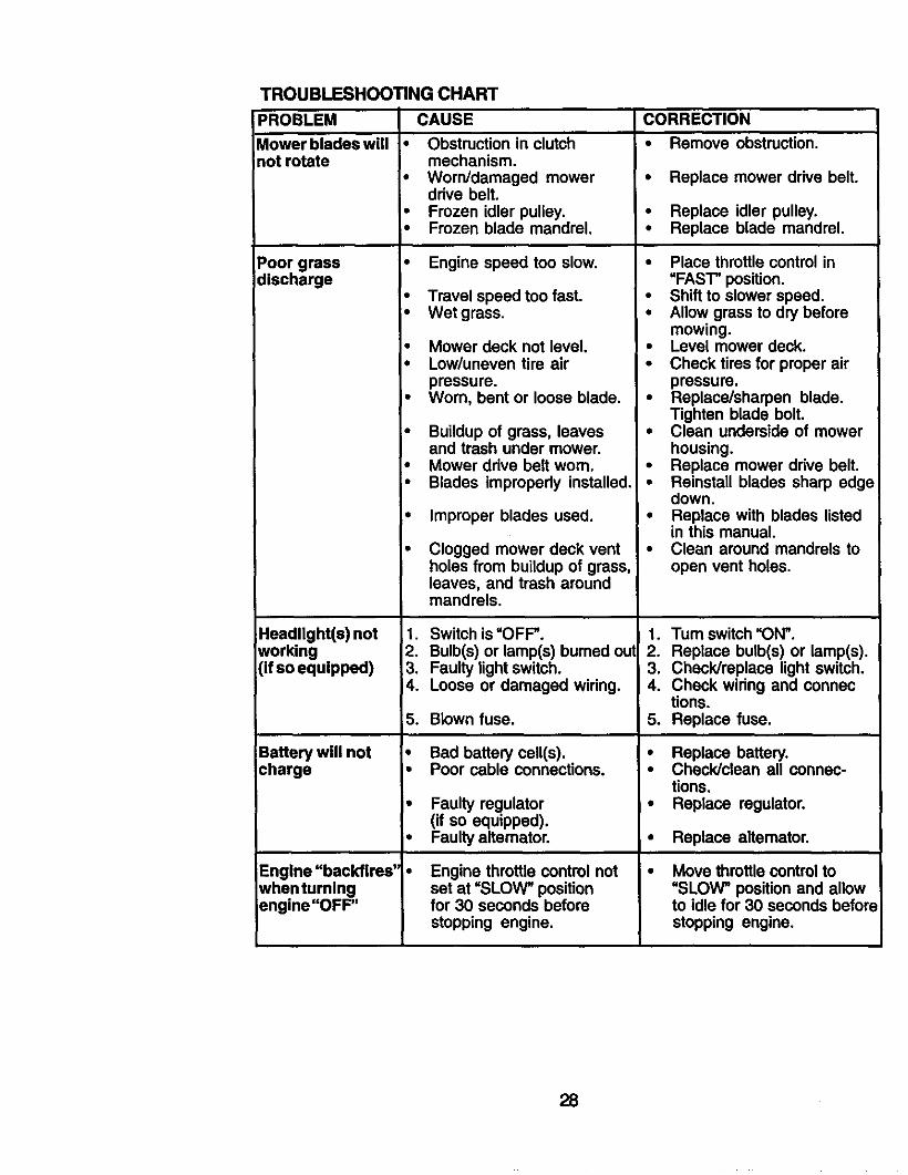
PROBLEM
Mower blades willnot rotate
TROUBLESHOOTING CHART
CAUSE
• Obstruction in clutchmechanism.
Poor grassdischarge
Headlight(s) notworking(if so equipped)
Battery will notcharge
Engine "backfires'whentumingengine "OFF"
• Worn/damaged mowerdrive belt.
• Frozen idler pulley.• Frozen blade mandrel.
• Engine speed too slow.
• Travel speed too fast.• Wet grass.
• Mower deck not level,• Low/uneven tire air
pressure.• Wom, bent or loose blade.
• Buildup of grass, leavesand trash under mower.
• Mower drive belt worn.• Blades improperly installed,
• Improper blades used.
Clogged mower deck ventholes from buildup of grass,leaves, and trash aroundmandrels.
1. Switch is =OFF".2. Bulb(s) or lamp(s) bumed out3. Faulty light switch.4. Loose or damaged wiring.
5. Blown fuse.
• Bad battery cell(s).• Poor cable connections.
• Faulty regulator(if so equipped).
• Faulty altemator.
Engine throttle control notset at =SLOW" positionfor 30 seconds beforestopping engine.
CORRECTION
• Remove obstruction.
• Replace mower drive belt.
• Replace idler pulley.• Replace blade mandrel.
• Place throttle control in=FAST" position.
• Shift to slower speed.• Allow grass to dry before
mowing.• Level mower deck.• Check tires for proper air
pressure.• Replace/sharpen blade.
Tighten blade bolt,• Clean underside of mower
housing.• Replace mower drive belt.• Reinstall blades sharp edge
down.• Replace with blades listed
in this manual.• Clean around mandrels to
open vent holes.
1. Turn switch =ON".2. Replace bulb(s) or lamp(s).3. Check/replace light switch.4. Check wiring and connec
tions.5. Replace fuse.
• Replace battery,,. Check/clean all connec-
tions.• Replace regulator.
• Replace altemator,
Move throttle control to"SLOW" position and allowto idle for 30 seconds befor=stopping engine.
28
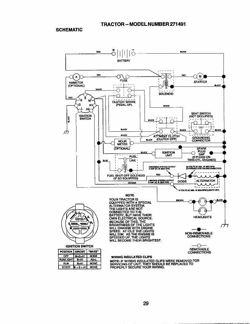
TRACTOR - MODEL NUMBER 271491SCHEMATIC
REO
BATTERY
REO
AMMETER
(OPTIONAL)
IGNITIONSWITCH
IGNmON SWITCH
SOLENOID
mACK (CLUTCH OFF)
eu_ _ IGNITION
STARTER
SEAT SWITCH(NOTCCCUPIED)
SPARK____@ PLUGGAP
2 PLUGSONTWI_ CYL ENGINES)
HEADLIGHTS
---e--NON-REMOVABLE
CONNECTIONS
REMOVABLECONNECTIONS
NOTEYOUR TRACTOR ISEQUIPPED WiTH A SPECIALALTERNATOR SYSTEM.THE UGHTS ARE NOTCONNECTED TO THEBATTERY, BUT HAVE THEIROWN ELECTRICAL SOURCE.BECAUSE OF THIS, THEBRIGHTNESS OF THE UGHTSWILL CHANGE WITH ENGINESPEED. AT IDLE THE LIGHTSWILL DIM. AS THE ENGINE ISSPEEDED UP, THE LIGHTSWILL BECOME THEIR BRIGHTEST.
F,
WIRING INSULATED CLIPSNOTE: IF WIRING INSULATED CLIPS WERE REMOVED FORSERVICING OF UNIT, THEY SHOULD BE REPLACED TOPROPERLY SECURE YOUR WIRING.
29
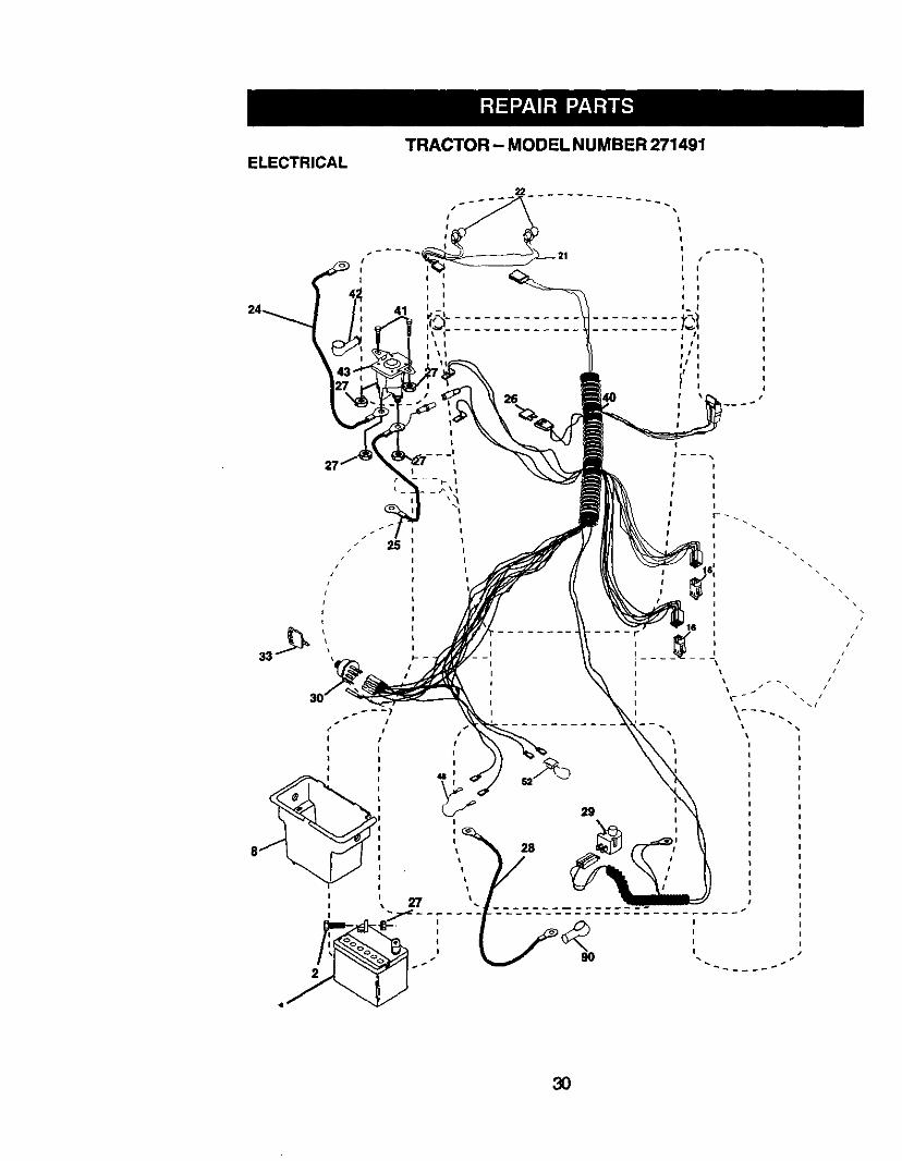
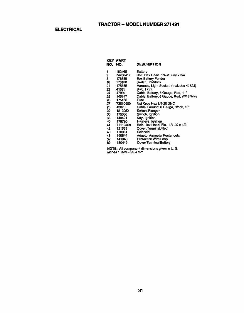
TRACTOR - MODEL NUMBER 271491ELECTRICAL
26
25
• I
/ I
I I
I I
I I
I 1
I
I
I
I
r
i
i
i
t
i
i
I I
t I
I_ t
II
I i
I
I
I
I
I
I
I
I
/
//
i \ /I
__J
I
III
3O
TRACTOR - MODEL NUMBER 271491ELECTRICAL
KEY PARTNO. NO. DESCRIPTION
1 163465 Battery2 74760412 Bolt, Hex Head 1/4-20 unc x 3/48 176689 Box Battery Fender16 176138 Switch, Intedock21 175685 Harness, Ught Socket (InCludes4152J)22 4152J Bulb, Light24 4799J Cable, Battery, 6 Gauge, Red, 11•25 146147 Cable, Battery, 6 Gauge, Red, W/16 Wire26 175158 Fuse27 73510400 Nut Keps Hex 1/4-20 UNC28 4207J Cable, Ground, 6 Gauge, Black, 12"29 121305X Switch,Plunger30 175566 Switch, Ignition33 140401 Key, Ignition40 179720 Harness, Ignition41 71110408 Bolt, Hex Head, Fin. 1/4-20 x 1/242 131563 Cover,Terminal, Red43 178861 Solenoid48 140844 AdaptorAmmeter Rectangular52 141940 ProtectionWire Loop89 180449 Cover Terminal Battery
NOTE: All componentdimensionsgiven in U. S.inches I inch= 25.4 mm
31
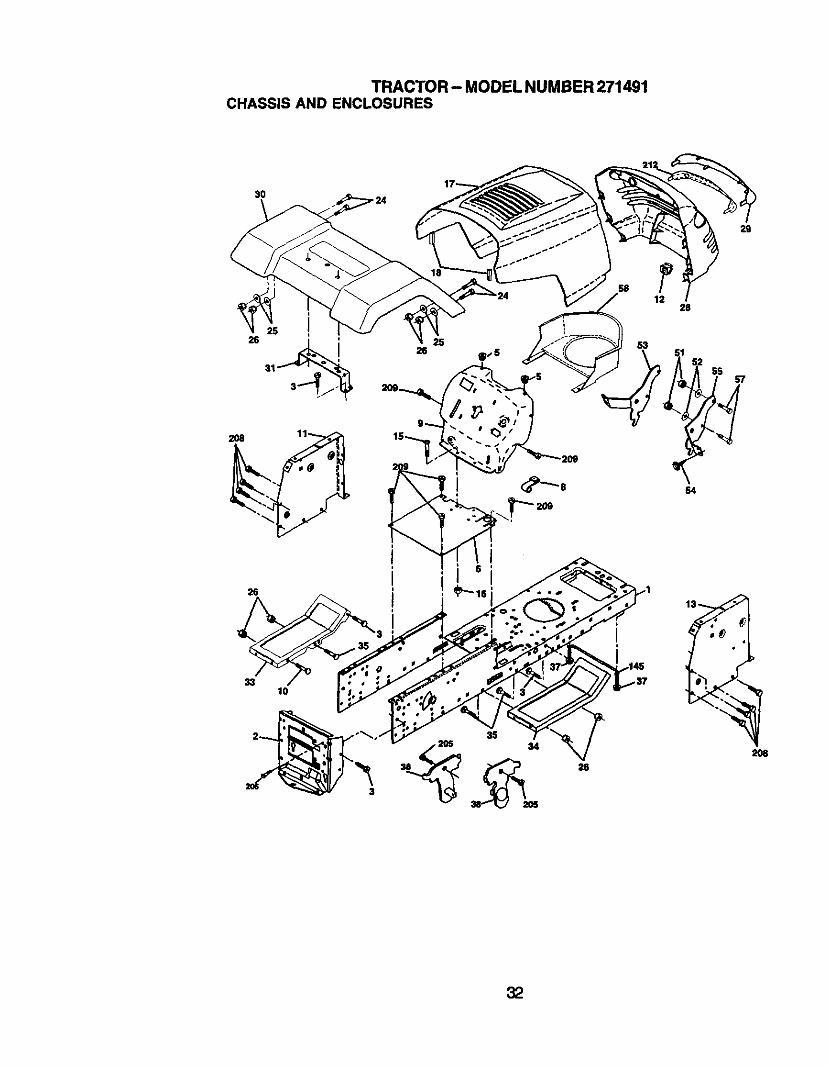
TRACTOR- MODEL NUMBER 271491CHASSIS AND ENCLOSURES
29
2O8
lO
3S
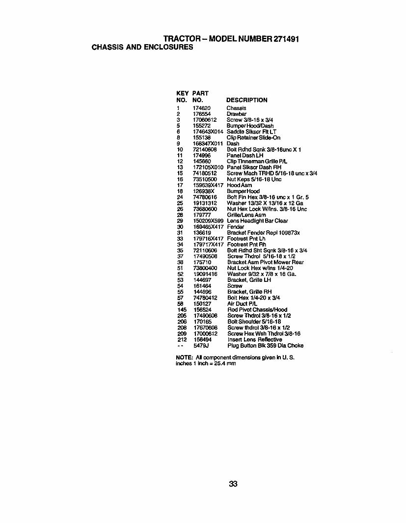
TRACTOR - MODEL NUMBER 271491CHASSIS AND ENCLOSURES
KEY PARTNO. NO. DESCRIPTION
1 174620 Chassis2 176554 Drawbar3 17060612 Screw 3/8-16 x 3/45 155272 BumperHood/Dash6 174643X014 Saddle Slkocr Fit LT8 155138 ClipRetainerSlide-On9 168347X011 Dash10 72140608 Bolt Rdhd Sqnk 3/8-16unc X 111 174996 Panel Dash LH12 145660 ClipTinnerman GdlleP/L13 172105X010 Panel SIkscr Dash RHt5 74180512 Screw Mach TRHD 5/16-18 unc x 3/416 73510500 Nut Keps 5/16-18 Uric17 159639X417 HoodAsm18 126938X BumperHood24 74780616 Bolt Fin Hex 3/8-16 uncx 1 Gr. 525 19131312 Washer 13/32 X 13/16 x 12 Ga26 73680600 Nut Hex Lock W/Ins. 3/8-16 Unc28 179777 Gdlle/l.ens Asm29 150209X599 Lens Headlight BarClear30 169465X417 Fender31 136619 Bracket Fender Rep1109873x33 179716X417 Footrest Pnt Lh34 179717X417 Footrest Pnt Rh35 72110606 Bolt Rdhd Sht Sqnk 3/8-16 x 3/437 17490508 Screw Thdrol 5/16-18 x 1/238 175710 Bracket Asm Pivot Mower Rear51 73800400 Nut Lock Hex w/Ins 1/4-2052 19C91416 Washer 9/32 x 7/8 x 16 Ga.53 144697 Bracket, Grille LH54 161464 Screw55 144696 Bracket, Grille RH57 74780412 Bolt Hex 1/4-20 x 3/458 150127 Air Duct PiL145 156524 Rod Pivot Chassis/Hood205 17490608 Screw Thdrol 3/8-16 x 1/2206 170165 BoltShoulder 5/16-18208 17670608 Screw thdrol 3/8-16 x 1/2209 17000612 Screw Hex Wsh Thdrol3/8-16212 156494 Insert Lens Reflective. - 5479J Plug Button BIk359 Dia Choke
NOTE: All component dimensionsgiven in U. S.inches 1 inch = 25.4 mm
33
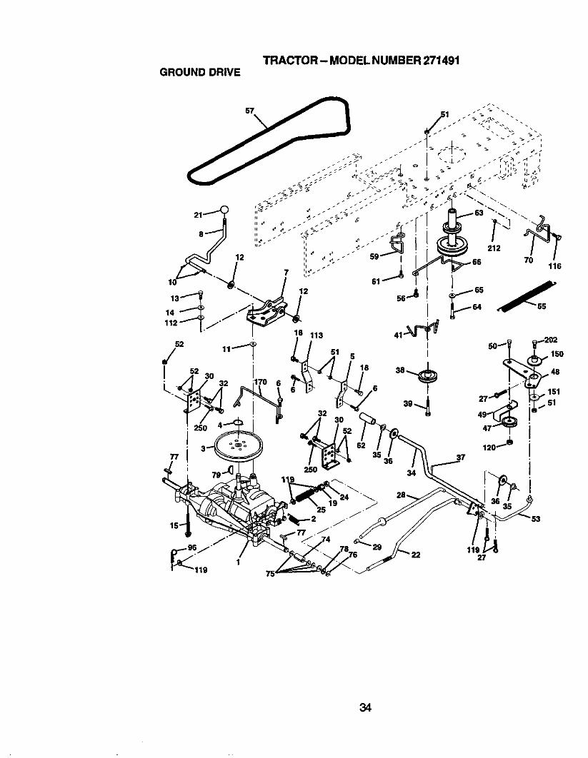
TRACTOR - MODEL NUMBER271491GROUNDDRIVE
i
11927
34

TRACTOR - MODEL NUMBER 271491GROUNDDRIVE
KEY PARTNO. NO.1 ......
2 1466823 123666X4 120000285 121520X6 1706G5127 1622408 13167910 7602041611 105701X12 1915121613 7455041214 1004040015 7449054418 7478061619 7380060021 106933X22 13080424 7335060025 106888X27 7602041228 17576529 7167330 174973-'_ 7476051234 17557835 120183X36 1921161637 1572H38 17911439 7476064841 17555647 12778348 15440749 123205X
KEY PARTDESCRIPTION NO, NO.Transaxle Dana D4360-139 50 74760624(Order parts tram transaxle 51Manufacturer) 52 73680500Spring Return Brake T/a Zinc 53 105710XPulley Tran_'de 18,'20"tiras 55 105709XRing Retainer# 5100-62 56 17060620Strap Torque 30 Degrees 57 160855Screw 5,'16-18 x 3/4 59 169691Bracket Saddle Shift T/a 61 17120614Rod Shf Sdl LY/YT Str BIk (_2 8883RPin Cotter 1/6 x I Cad 63 175410Washer Plate388 Sq Hole 64 71170764Washer 15/32 x 3/4 x 16ga 65 10040700Bolt 114-28unfGr8 W/Patch 66 154778Washer Lock Hvy Helical 1/4 70 134683Bolt Hex Flghd 5/16-18 x Gr. 5 74 109502XBolt Fin Hex 3/8-16 UNC x 1 Gr. 5 75 121749)(Nut Lock Hex W/Ins. 3/8-16 Unc 76 12000001Knob Rd 1/2-13 PlstcThds 77 123583XRod Blake BIk Zinc 26 840 78 121748)(Nut Hex Jam 3/8-16 Unc 79 2228MSpring Rod Brake 2 00 Zinc 96 4497HPin Cotter 1/8 x 3/4 Cad 112 19091210Rod Brake Parking Lt/Yt 113 127285XCap Brake Parking 116 72140608Bracket MtgTransaxle 119 19131016Bolt Hex Hd 5/16-18unc x 3/4 120 73900600ShaftAsm Pedal Foot Nibbed 150 175456Bearing Nylon BIk 629 Id 151 19133210Washer 21/32 x 1 x 16 Ga 176 178394Pin Roll 3/16 X 1" 202 72110614PulleyComposite Flat 212 145212BoltFin Hex 3/6-16 UNC x 3 Gr. 5 250 17060612Keeper Belt IdlerPulley Idler V Groove PlasticBollcrank Asm. ClutchRetainer Belt Style Spring
DESCRIPTIONBoltHex Hd 3/8-16unc x1-1/2HutCrowniock 3/6-16 UNCNut CrownLock 5/16-16Link Clutch7 66Sp_ng Return Clutch 6 75Screw 3/8-16 x 1-1/4V-Belt Gd Drive 9530Keeper BeltCentarspenScrew 3/6-16 x .875Cover Pedal BlkRoundPulley Eng CICableBolt Hex 7/16-20 x 4 Gr 5Washer Lock Hid Spr 7/16Kceper Belt Engine FPGuide BeltMower Ddve RHSpacer AxleWasher 25/32 x 1-1/4 x16 GaE-dng#5133-75Key Square 2 0 x 1845/1865Washer 25/32 x1-5/8 x 16 GaKey Woodruff #9 3/16 x 3/4RetainerSpring 1Washer 9/32 x 3/4 x 10 GaStrapTorque LH LTBolt 3/8-16 x 1Washer 13/32 x 5/8 x 16 GaNut Lock Fig 3/8-16Spacer RetainerWasher 13/32 x 2 x 10 Ga.Keeper Belt Traneaxle GearBolt Cart. Sh 3/8-16 x 1-3/4 Gr. 5Nut Hax Flange LockScrew 3/8-16 x 3/4
NOTE: An compt_nt dimensionsgiven in U. S.inches 1 inch= 25.4 mm
35
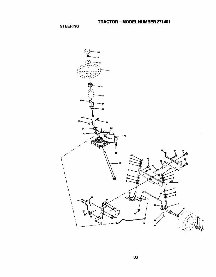
TRACTOR - MODEL NUMBER 271491STEERING
s _ .
t," i, _ •
• _ ___'_1 I
t i
°J.J
°J
\i
\i
\
TRACTOR- MODEL NUMBER 271491STEERING
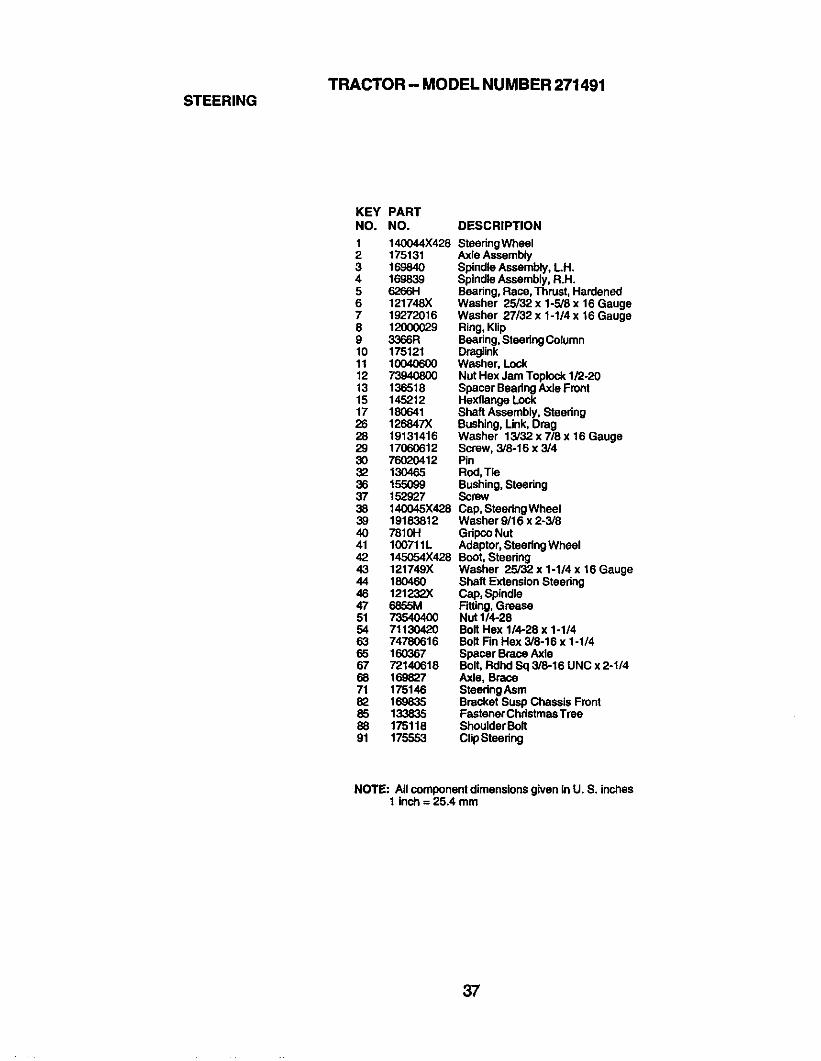
KEY PARTNO. NO. DESCRIPTION
1 140044X428 SteodngWheel2 175131 Axle Assembly3 169840 Spindle Assembly,LH.4 16,9839 SpindleAssembly, R.H.5 6266H Bearing, Race, Thrust,Hardened6 121748)( Washer 25/32 x 1-5/6 x 16 Gauge7 19272016 Washer 27/32 x 1-1/4 x 16 Gauge8 12000029 Ring,Klip9 3366R Beadng, SteedngColumn10 175121 Dmglink11 10040600 Washer, Lock12 73940800 Nut Hex Jam Toplock 1/2-2013 136518 Spacer Beadng Axle Front15 145212 Hexflange Lock17 180641 Shaft Assembly, Stoedng26 126847X Bushing, Link, Drag28 19131416 Washer 13/32 x 7/8 x 16 Gauge29 17060612 Screw, 3/8-16 x 3/430 76020412 Pin32 130465 Rod, Tie36 155099 Bushing,Steering37 152927 Screw38 140045X428 Cap, Steedng Whael39 19183812 Washar 9/16 x 2-3/840 781OH Gripco Nut41 100711L Adaptor,Steedng Wheel42 145054X428 Boot, Steering43 121749X Washer 25/32 x 1-1/4 x 16 Gauge44 180460 Shaft Extension Steedng46 121232X Cap, Spindle47 68&SM Fitting, Grease51 73540400 Nut 1/4-2854 71130420 Bolt Hex 1/4-28 x 1-1/463 74780616 Bolt Fin Hex 3/8-16 x 1-1/465 160367 Spacer Brace Axle67 72140618 Bolt, Rdhd Sq 3/8-16 UNC x 2-1/468 169827 Axle, Brace71 175146 SteedngAsm82 169835 Bracket Susp Chassis Front85 133835 Fastener ChdstmasTrae88 175118 Shoulder Bolt91 175553 Clip Steering
NOTE: All componentdimensions given in U. S. inches1 inch = 25.4 mm
37
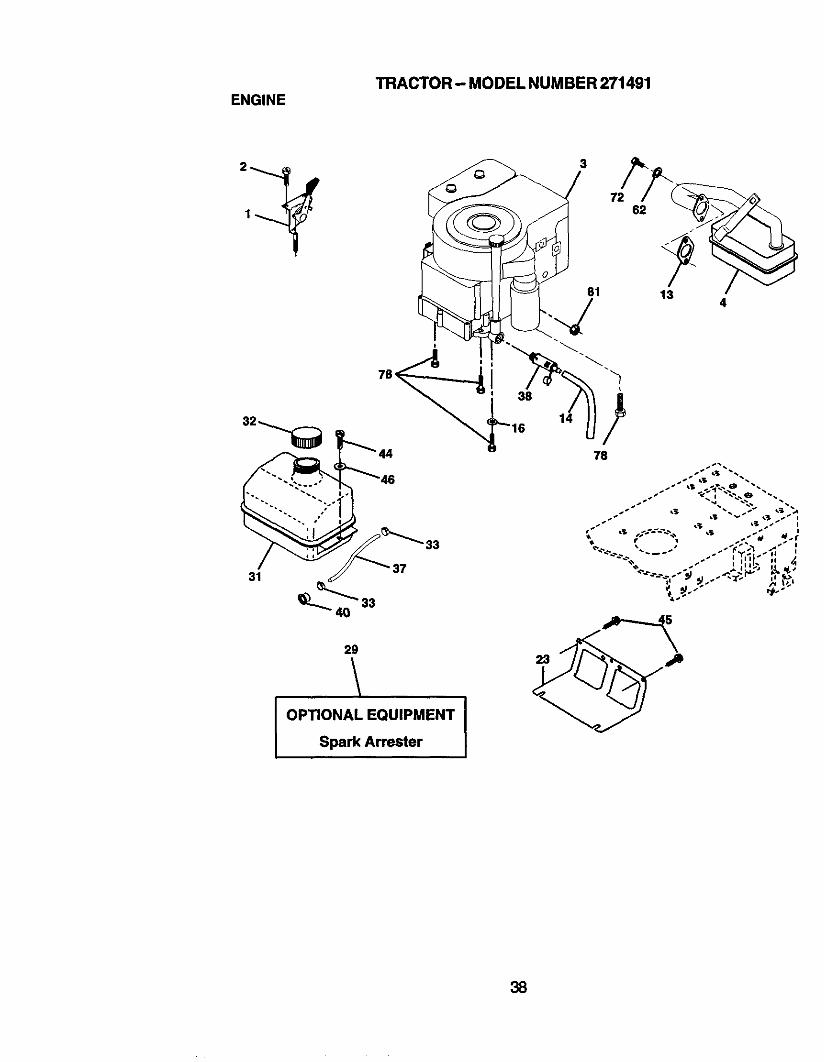
TRACTOR -- MODEL NUMBER 271491ENGINE
31
33
3
81
78
29
I OPTIONAL EQUIPMENTSpark Arrester
23
38
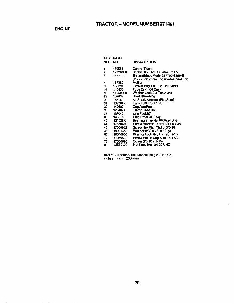
TRACTOR- MODEL NUMBER 271491ENGINE
KEY PARTNO. NO. DESCRIPTION
123
17055117720408
4 13735213 16529114 14845616 1105060023 16983729 13718031 109202)(32 14052733 123487x37 13704038 14831540 124028)(44 1767041245 1700061246 1909141662 1004o5oo72 7107051278 1706062081 73510400
ControlTWchScrew Hex Thd Cut 1/4-20 x 1/2Engine BdggsModel287707-1259-E1(Order parts from Engine Manufacturer)MufflerGasket Eng 1 313 Id Tin PlatedTube Drain Oil EasyWasher Lock Ext Tooth 3/8ShieldBrowningKit Spark Arrestor (Flat Scm)Tank Fuel Front I 25Cap Asm FuelClamp Hose BIkLineFuel 20"Plug Drain Oil EasyBushingSnap Nyl BIk Fuel UneScrew Hexwsh Thdrol 1/4-20 x 3/4Screw Hex WshThdrol3/8-16Washer 9/32 x 718 x 16 gaWasher Lock Hvy Hlcl Spr 5/16Screw Hexhd Cap 5/16-18 x 3/4Screw 3/8-16 x 1-1/4Nut Keps Hex 1/4-20 UNC
NOTE: All componentdimensionsgiven in U. S.inches 1 inch = 25.4 mm
39
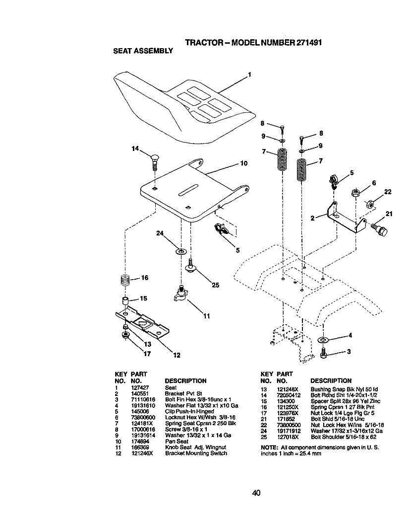
TRACTOR- MODEL NUMBER 271491SEATASSEMBLY
KEY PART KEY PARTNO, NO. DESCRIPTION NO. NO,
1 127427 Seat 13 121248X2 140551 Bracket Pvt St 14 720504123 71110616 Bolt Fin Hex 3/8-16unc x 1 15 1343004 19131610 Washer Fiat 13/32 xl xl0 Ga 16 121250X5 145006 Clip Push-In Hinged 17 123976X6 73800600 Locknut Hex W/Wsh 3/8-16 21 1718527 124181X SpringSeat Cprsn 2 250 BIk 22 738005008 17000616 Screw 3/8-16 x I 24 191719129 19131614 Washer 13/32 x I x 14 Ga 25 127018X10 174894 Pan Seat11 166369 Knob Seat Adj. Wingnut12 121246)( Bracket MountingSwitch
DESCRIPTION
BushingSnap BIkNy150 IdBolt Rdhd Sht 1/4-20x1-1/2Spacer Split28x 96 Yel ZincSpringCprsn 1 27 BIk PntNut Lock 1/4 Lge Fig Gr 5Bolt Shld 5/16-18 UncNut Lock Hex W/Ins 5/16-18Washer 17/32 x1-3/16x 12 GaBolt Shoulder 5/16-18 x 62
NOTE: All componentdimensionsgiven in U, S.inches 1 Inch = 25.4 mm
4O
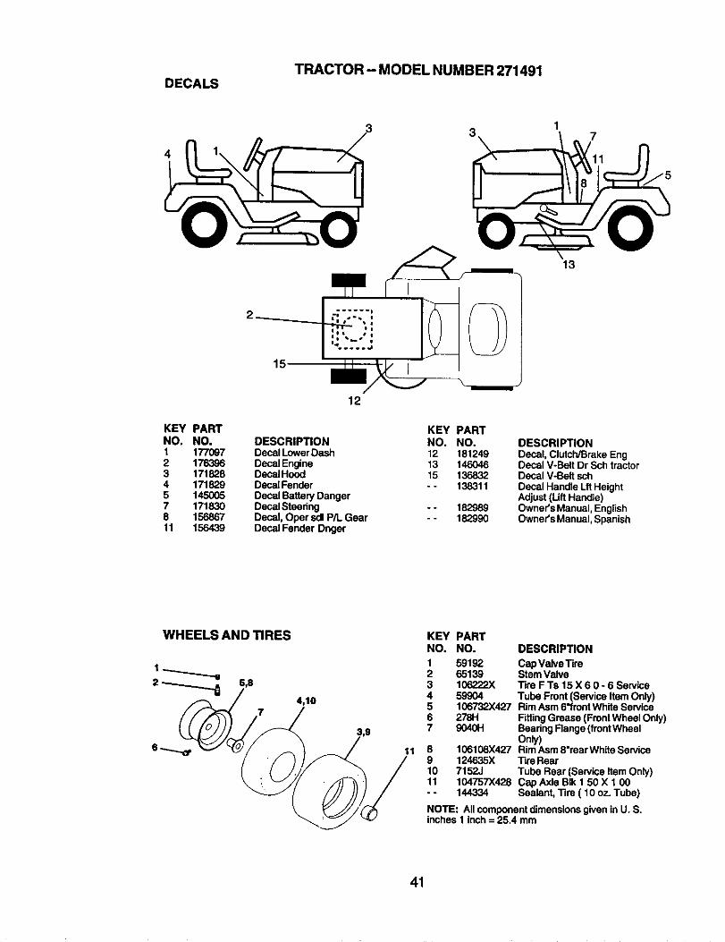
TRACTOR- MODEL NUMBER 271491DECALS
7
13
15
KEY PARTNO. NO.1 1770972 1763963 1718284 1718295 1450057 1718308 15686711 156439
12
KEY PARTDESCRIPTION NO. NO.Decal Lower Dash 12 181249Decal Engine 13 146046Decal Hood 15 136832Decal Fender - - 138311Decal Battery DangerDecal Steedng - - 182989Decal, Oper sdl P/I. Gear - - 182990Decal Fender Dnger
DESCRIPTIONDecal, Clutch/Brake EngDecal V-Bait Dr Sch tractorDecal V-BeR schDecal Handle Lit HeightAdjust (LiftHandle)Owner's Manual, EnglishOwner's Manual, Spanish
WHEELS AND TIRES
4,10
11
KEY PARTNO. NO.
1 591922 651393 106222X4 599O45 106732X4276 278H7 9040H
8 106108X4279 124635X10 7152J11 104757X428-- 144334
DESCRIPTION
Cap ValveTireStem ValveTire F Te 15 X 6 0 - 6 ServiceTube Front (Service Item Only)Rim Asm 6"frontWhite ServiceFittingGrease (FrontWheel Only)Bearing Flange (frontWheelOnly)Rim Asm8"rear White ServiceTire RearTube Rear (Service Item Only)Cap Axle BIk 1 50 X 1 00Sealant, 11re ( 10 oz. Tube)
NOTE: Allcomponent dimensionsgiven in U. S.inches I inch = 25.4 mm
41
TRACTOR - MODEL NUMBER 271491LIFT ASSEMBLY
7
8
5
13
46
3
2
6
19
13
13---o,*32
13
1915
42
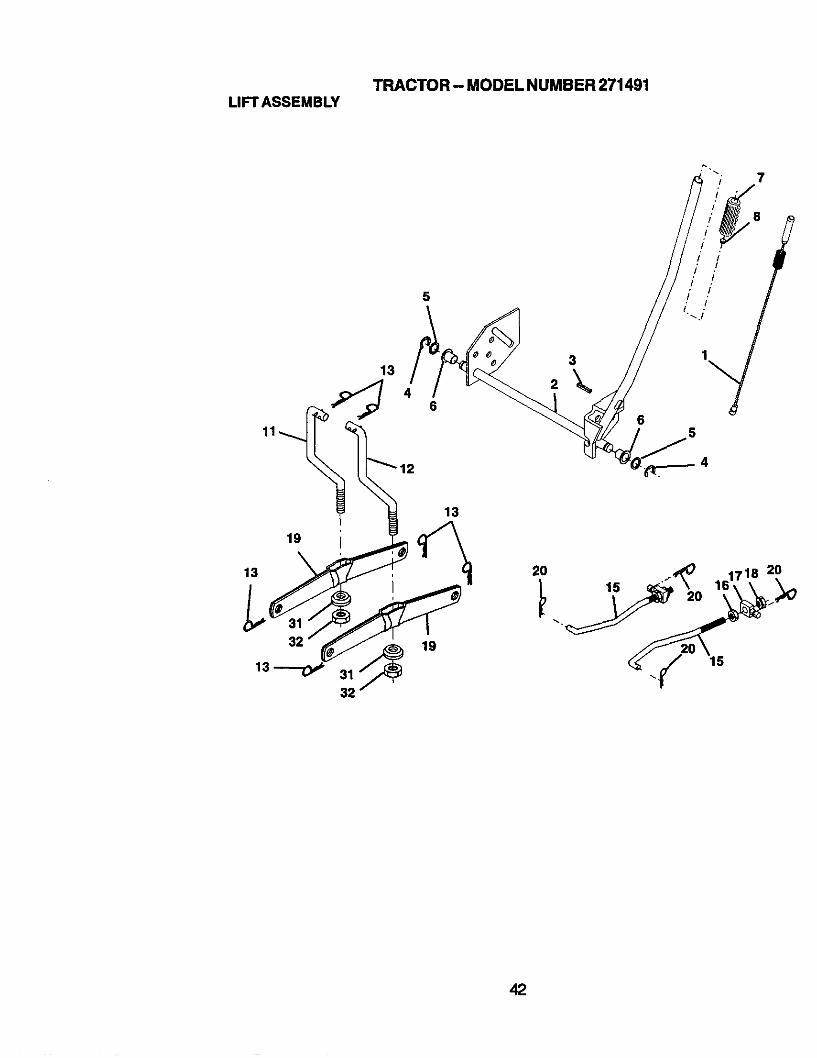
TRACTOR- MODEL NUMBER 271491LIFTASSEMBLY
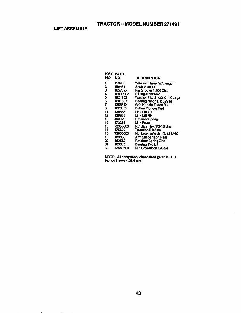
KEY PARTNO, NO, DESCRIPTION
1 159460 Wire Asm Inner W/plunger2 159471 Shaft Asm Lift3 105767X Pin Groove 1 500 Zinc4 12000002 E Ring#5133.625 19211621 Washer Pltd21/32 X 1 X 21ga6 120183X Bearing Nylon BIk629 Id7 125631X Grip Handle FlutedBIk8 122365X Button Plunger Red11 139865 Link Uft LH12 139866 Link Lift RH13 4939M RetainerSpring15 173288 Link Front16 73350800 Nut Jam Hex 1/2-13 Unc17 175689 Trunnion BIkZinc18 73800800 Nut Lock w/Wsh 1/2-13 UNC19 139868 ArmSuspensionRear20 163552 Retainer SpdngZinc31 169865 Beadng Pvt Lift32 73540600 Nut Crownlock 3/8-24
NOTE: All componentdimensions given in U. S.inches 1 inch = 25.4 mm
43
TRACTOR - MODEL NUMBER 271491MOWERDECK
2
2
11
2
24
I
29
28 26
I
44
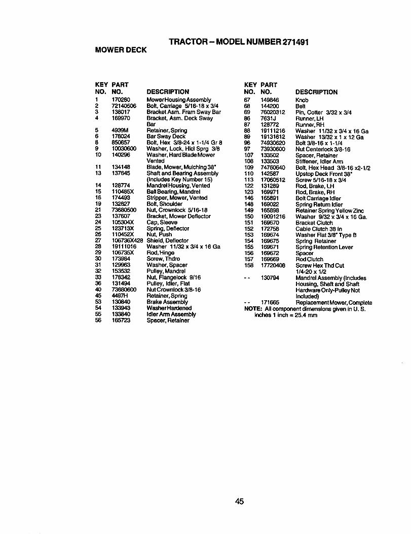
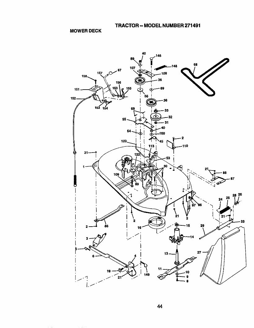
TRACTOR - MODEL NUMBER 271491MOWER DECK
KEY PARTNO. NO.
1 1702802 721405063 1380174 169970
5 4939M6 178(_48 8508579 10O3O6O010 140296
11 13414813 137645
14 12877415 110485X16 17449319 13282721 7368050023 13760724 105304X25 123713X26 110452X27 106736X42828 1911101629 106735X30 17398431 12996332 15353233 17834236 1314944O 7368060045 4497H53 13O84O54 13394355 13384O56 165723
KEY PARTDESCRIPTION NO. NO.
MowerHousingAssembly 67 149846Bolt, Carriage 5/16-18 x 3/4 68 144200BracketAsm. Fram Sway Bar 69 76020312Bracket, Asm. Deck Sway 86 7631JBar 87 128772Retainer,Spdng 88 19111216Bor Sway Deck 89 19131612Bolt, Hax 3/8-24 x 1-1/4 Gr 8 96 74930620Washer, Lock, Hid Sprg 3/8 97 73930600Washer, Hard BladeMower 107 133502Vented 108 133503Blade,Mower, Mulching38" 109 74760640Shaft and Bearing Assembly 110 142587(IncludesKey Number 15) 113 17060512Mandrel Housing,Vented 122 131289BallBearing,Mandrel 123 169971Stripper,Mower, Vented 146 165891Bolt, Shoulder 148 169022Nut, Crownlock 5/16-18 149 165898Bracket, Mower Deflector 150 19091216Cap, Sleeve 151 169670Spring, Deflector 152 172758Nut, Push 153 169674Shield, Deflector 154 169675Washer 11i32x3/4x16Ga 155 169671Red, Hinge 156 169672Screw, Thdro 157 169669Washer, Spacer 158 17720408Pulley, MandrelNut, Flangelock 9/16 - - 130794Pulley, Idler, FlatNUtCrownlock3/6-16Retainer,SpringBrake Assembly - - 171665WashorHan_enedIdlerArmAssemblySpacer, Retainer
DESCRIPTION
KnobBeltPin, Cotter 3/32 x 3/4Runner,LHRunner,RHWasher 11/32 x 3/4 x 16 GaWasher 13/32 x 1 x 12 GaBolt 3/8o16 x 1-1/4Nut Centeriock3/8-16Spacer, RetainerStiffener, Idler ArmBolt, Hex Head 3/8-16 x2-1/2Upstop Deck Front38"Screw 5/16-18 x 3/4Rod, Brake, LHRod, Brake, RHBoltCarriage idlerSpdngRetum IdlerRetainerSpringYellowZincWasher 9/32 x 3/4 x 16 Ga.Bracket ClutchCable Clutch38 InWasher Flat 3/8" Type BSpring RetainerSpringRetentionLeverSpacerRodClutchScrew Hex Thd CUt1/4-20 x 1/2Mandrel Assembly (IncludesHousing, Shaft and ShaftHardware Only-PulleyNotIncluded)ReplacementMower,Complete
NOTE: All componentdimensions given in U. S.inches 1 inch = 25.4 mm
45
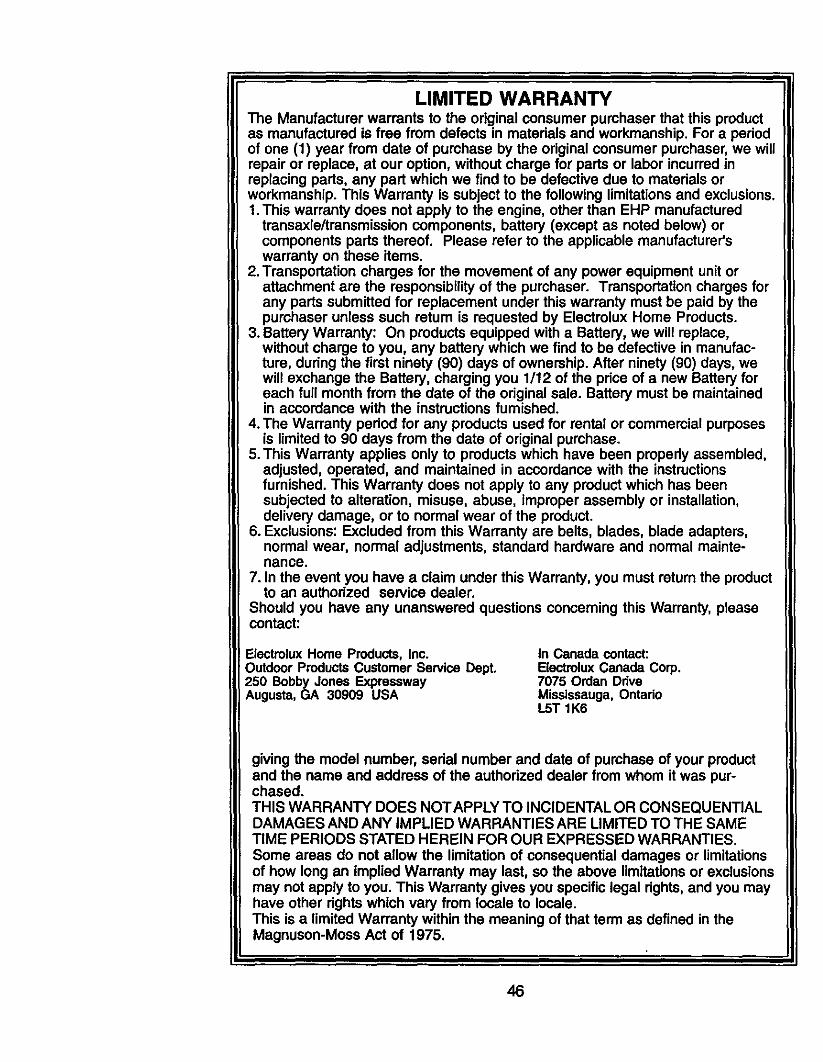
LIMITED WARRANTYThe Manufacturer warrants to the original consumer purchaser that this productas manufactured is free from defects in materials and workmanship. For a periodof one (I) year from date of purchase by the original consumer purchaser, we willrepair or replace, at our option, without charge for parts or labor incurred inreplacing parts, any part which we find to be defective due to materials orworkmanship. This Warranty Is subject to the following limitations and exclusions.1. This warranty does not apply to the engine, other than EHP manufactured
transaxle/transmission components, battery (except as noted below) orcomponents pads thereof. Please refer to the applicable manufacturer'swarranty on these items.
2. Transportation charges for the movement of any power equipment unit orattachment are the responsibility of the purchaser. Transportation charges forany parts submitted for replacement under this warranty must be paid by thepurchaser unless such return is requested by Electrolux Home Products.
3. Battery Warranty: On products equipped with a Battery, we will replace,without charge to you, any battery which we find to be defective in manufac-ture, during the first ninety (90) days of ownership. After ninety (90) days, wewill exchange the Battery, charging you 1/12 of the price of a new Battery foreach full month from the date of the original sale. Battery must be maintainedin accordance with the instructions fumished.
4. The Warranty pedod for any products used for rental or commercial purposesis limited to 90 days from the date of original purchase.
5.This Warranty applies only to products which have been properly assembled,adjusted, operated, and maintained in accordance with the instructionsfurnished. This Warranty does not apply to any product which has beensubjected to alteration, misuse, abuse, improper assembly or installation,delivery damage, or to normal wear of the product.
6. Exclusions: Excluded from this Warranty are belts, blades, blade adapters,normal wear, normal adjustments, standard hardware and normal mainte-nance.
7. In the event you have a claim under this Warranty, you must return the productto an authorized service dealer.
Should you have any unanswered questions concerning this Warranty, pleasecontact:
Electmlux Home Products, Inc.Outdoor Products Customer Service Dept.250 Bobby Jones ExpresswayAugusta, GA 30909 USA
In Canada contact:Electrolux Canada Corp,7075 Ordan DdveMississauga, OntadoL5T 1K6
giving the model number, serial number and date of purchase of your productand the name and address of the authorized dealer from whom it was pur-chased.THIS WARRANTY DOES NOTAPPLY TO INCIDENTAL OR CONSEQUENTIALDAMAGES AND ANY IMPLIED WARRANTIES ARE LIMITED TO THE SAMETIME PERIODS STATED HEREIN FOR OUR EXPRESSED WARRANTIES.
Some areas do not allow the limitation of consequential damages or limitationsof how long an implied Warranty may last, so the above limitations or exclusionsmay not apply to you. This Warranty gives you specific legal rights, and you mayhave other dghts which vary from locale to locale.This is a limited Warranty within the meaning of that term as defined in theMagnuson-Moss Act of 1975.
46

SUGGESTED GUIDE FOR SIGHTING SLOPES FOR SAFE OPERATION
1. Fold this page along dotted line Indicated above.2. Hold page before you so that Its left edge Is vertically parallel to s tree
trunk or other upright structure.3. Sight across the fold In the direction of hill slope you want to measure.4. Compare the angle of the fold with the slope of the hill.

Poulan


![Oliver Strange - Sudden Westerns 06 - Sudden Gold-Seeker(1937)[1]](https://img.pdfslide.us/doc/110x75/54fae2e44a7959575b8b4b9b/oliver-strange-sudden-westerns-06-sudden-gold-seeker19371.jpg)