Embed Size (px)
Citation preview

perator's
I:RnFrSMRN°30 in. Two Bin Rear Bagger
for the Craftsman Rear Engine Rider 1000
Model No. 247.240690
\ \
/
• Espanol, P. 14
Before using this equipment,read this manual and follow
all safety rules and operatinginstructions.
For answers to your questions aboutthis product, call:
1-800-659-5917CraftsmanTractorHelp Line7 am = 7 pm CT, Mort. =Sun.
Sears Brands Management Corporation, Hoffman Estates, IL 60179, U.S.A.Visit our website: www.craftsman.com
FormNo.769-08596
(December17,2012)

Craftsman One Year Full WarrantyFORONEYEARfromthe dateof purchase,this productis warrantedagainstanydefectsin materialor workmanship.A defectiveproductwill bereplacedfreeof charge.
Forwarrantycoveragedetailsto obtainfree replacement,visit theweb site:www.craftsman.com
Thiswarrantydoesnotcovergrassbagassemblies,whichareexpendablepartsthatcanwearoutfromnormalusewithinthewarrantyperiod.
Thiswarrantyis void if thisproductis everusedwhile providingcommercialservicesor if rentedto anotherperson.
Thiswarrantygivesyou specificlegal rights,andyou mayalso haveotherrightswhichvaryfromstateto state.
Sears Brands Management Corporation, Idoffman Estates, IL 60179
© SearsBrands,LLC 2
Thissymbolpointsoutimportantsafety instructionswhich,if not
followed, couldendangerthe personalsafetyand/orproperty of
yourselfandothers. Readandfollow all instructionsin this manual
beforeattempting to operatethis machine.Failureto complywith these
instructionsmayresultinpersonalinjury.Whenyouseethis symbol,HEEDITSWARNING!
CALiFORNiA PROPOSITION 65
EngineExhaust,someof itsconstituents,andcertainvehiclecomponentscontain oremit chemicalsknownto Stateof Californiato causecancerand
birth defectsor other reproductiveharm.
Battery posts,terminals,and relatedaccessoriescontain leadand lead
compounds,chemicalsknownto the Stateof Californiatocausecancerand
reproductiveharm.Washhandsafter handling.
Thismachinewasbuilt to beoperatedaccordingto thesafeoperation
practicesin this manual.Aswith anytype of powerequipment,
carelessnessorerroron the partof theoperatorcanresultinseriousinjury.
Thismachineiscapableof amputating fingers, hands,toesandfeet and
throwingdebris.Failureto observethe following safety instructionscould
resultinseriousinjuryor death.
Your Responsibility--Restrict theuseof this powermachineto
personswho read,understandandfollow thewarningsand instructionsinthismanualandon themachine.
SAVETHESEINSTRUCTIONS!
GENERAL OPERATION
Read,understand,andfollowall instructionsonyourequipmentandintheir
manualsbeforeattemptingto assembleandoperate.Keepthismanualin
asafeplaceforfutureandregularreferenceandfor orderingreplacement
parts.
Tohelpavoidbladecontactora thrownobjectinjury,keepbystanders,
helpers,childrenandpetsat least75feetfromthemowerwhile it isin
operation.Stopmachineifanyoneentersthearea.
Thoroughlyinspecttheareawheretheequipmentisto beused.Remove
all stones,sticks,wire, bones,toys,andotherforeignobjectswhichcould
bepickedupandthrownbytheblade(s).Thrownobjectscancauseserious
personalinjury.
Alwayswearsafetyglassesorsafetygogglesduringoperationandwhile
performinganadjustmentor repairto protectyoureyes.Thrownobjects
whichricochetcancauseseriousinjury to theeyes.
Donotoperatethemowerwithoutthedischargecoverorentiregrass
catcherin itsproperplace.A missingordamageddischargecoverorgrass
bagattachmentcomponentmayresultin thrownobjectsorbladecontact
injuries.
Donotputhandsor feetnearrotatingpartsorunderthecuttingdeck.
Contactwith theblade(s)canamputatehandsandfeet.
Shutoffmower'sengineandwait forbladesto cometo acompletestop
beforeuncloggingmower'sdischargeopeningorbaggerparts.
Slowdownbeforeturning.Operatethemachinesmoothly.Avoiderratic
operationandexcessivespeed.Beawarethata grasscatcherattachmentcan
affectthehandlingcharacteristicsofyourmower.
Disengageblade(s),setparkingbrake,stopengineandwaituntil the
blade(s)cometo a completestopbeforeopeningbaggerattachment'stop
cover,removinggrasscatcher,emptyinggrass,uncloggingchute,removing
anygrassordebris,or makinganyadjustments.
Neverleavea runningmachineunattended.Alwaysturn off blade(s),place
transmissioninneutral,setparkingbrake,stopengineandremovekey
beforedismounting.
Yourmachineisdesignedto cut normalresidentialgrassof aheightnomore
than 10".Donotattemptto mowthroughunusuallytall, drygrass(e.g.,
pasture)orpilesofdry leaves.Drygrassor leavesmaycontacttheengine
exhaustand/orbuilduponthemowerdeckpresentinga potentialfirehazard.
Ifsituationsoccurwhicharenotcoveredinthismanual,usecareandgood
judgment.
SLOPE OPERATION
Slopesarea majorfactorrelatedto lossofcontrolandtip-overaccidentswhichcan
resultinsevereinjuryordeath.Allslopesrequireextracaution.Ifyoucannotback
uptheslopeor if youfeeluneasyon it,donotmowit.
Foryoursafety,usetheSlopeGuideincludedaspart ofthismanualto measure
slopesbeforeoperatingthismachineonaslopedorhilly area.Iftheslopeis greater
than 10degreesasshownontheSlopeGuide,donotoperatethismachineon that
areaorseriousinjurycouldresult.
Do;
Mowupanddownslopes,notacross.Exerciseextremecautionwhen
changingdirectiononslopes.
Watchforholes,ruts,bumps,rocks,orotherhiddenobjects.Uneventerrain
couldoverturnthemachine.Tallgrasscanhideobstacles.
Useslowspeed.Choosealowenoughspeedsettingsothatyouwill nothave
to stoporshift whileon theslope.Tiresmaylosetractiononslopeseven
thoughthe brakesarefunctioningproperly.Alwayskeepmachineingear
whengoingdownslopesto takeadvantageof enginebrakingaction.
Followthemanufacturer'srecommendationsforwheelweightsor
counterweightsto improvestability.

Keepallmovementontheslopesslowandgradual.Donotmakesuddenchangesinspeedordirection.Rapidengagementorbrakingcouldcausethefrontofthemachinetoliftandrapidlyflipoverbackwardswhichcouldcauseseriousinjury.
Avoidstartingorstoppingona slope.Iftires losetraction,disengagethe
blade(s)andproceedslowlystraightdowntheslope.
Do Not:
Donot turn onslopesunlessnecessary;then,turn slowlyandgradually
downhill,ifpossible.
Donotmowneardrop-offs,ditchesorembankments.Themowercould
suddenlyturn overifawheelisovertheedgeof acliff,ditch,or ifanedgecavesin.
Donot try to stabilizethemachinebyputtingyourfooton theground.
Donotuseagrasscatcheronsteepslopes.
Donotmowonwetgrass.Reducedtractioncouldcausesliding.
GENERAL SERVICE
Beforecleaning,repairing,or inspecting,makecertaintheblade(s)andall
movingpartshavestopped.Disconnectthesparkplugwire andground
againsttheengineto preventunintendedstarting.
Keepallnuts,bolts,andscrewstightto besuretheequipmentisinsafeworkingcondition.
Nevertamperwith your mower'ssafetyinterlocksystemorother safetydevices.
Checktheir properoperationregularly.
Neverattempt to makeadjustmentsor repairswhile the mower'sengineisrunning.
Grasscatchercomponentsandthe dischargecoveraresubjectto wearanddamage
which couldexposemovingpartsorallow objectsto bethrown. Forsafety
protection,frequentlycheckcomponentsandreplaceimmediatelywith original
equipmentmanufacturer's(O.E.M.)partsonly,listed in this manual.Useof parts
which donot meetthe originalequipmentspecificationsmayleadto improper
performanceandcompromisesafety!
Maintainorreplacesafetyandinstructionlabels,asnecessary.
SAFETY SYMBOLS
Thispagedepictsanddescribessafetysymbolsthat mayappearon this product. Read,understand,andfollow all instructionson the machinebefore
attempting to assembleand operate.
%
READ THE OPERATOR'S MANUAL(S)
Read, understand, and follow all instructions in the manual(s) before attempting to assemble and
operate
STOP
Turn off the engine before opening the bagger cover.
WARNING: Your Responsibility--Restrict the useof this power machine to persons who read, understand and followthe warnings and instructions in this manual and on the machine.
SAVETHESEINSTRUCTIONS!
4
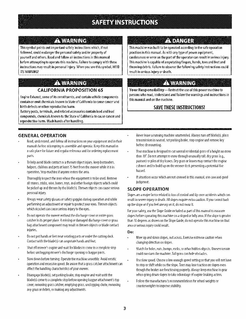
(OK)
10° Slope
(TOO STEEP)
10° Slope
Figure 1
USETHiSSLOPEGAUGETO DETERMINEiFA SLOPEiS TOOSTEEPFORSAFEOPERATION!
Tocheckthe slope,proceedas follows:1. Removethis pageandfold alongthe dashedline.2. Locateavertical objectonor behindthe slope(e.g.a pole,building,fence, tree,etc.)3. Aligneither sideof the slopegaugewith the object (SeeFigure1 andFigure2 ).4. Adjustgaugeup or down until the left cornertouchesthe slope(SeeFigure1 andFigure2).5.
10odashedline
If there is a gapbelowthe gauge,the slope is too steepfor safeoperation(SeeFigure2 above).
Figure2
Slopes are a major factor related to tip-over and roll-over accidents which can result in severe injury or death. Do not operate machine
on slopes in excess of 10 degrees. All slopes require extra caution. If you cannot back up the slope or if you feel uneasy on it, do not
mow it. Always mow up and down the face of slopes, never mow across the face of slopes.

Beforebeginninginstallation,removeall parts fromthe cartonto makesureeverythingis present.Cartoncontentsare listedbelowand shownbelow.A hardwarepackis includedinthis kitand is detailedonthe followingpage.
Two Grass Bag Assemblies
Grass Catcher Hood
Chute Tube
Bag Support Assembly
Mounting Bracket
CounterWeight
Counter Weight Mounting Bracket
One Hardware Pack (Detailedonthe nextpage)
6

Thisgrasscollectorkitis shippedwithahardwarepackenclosed.Pleasecheckyourhardwarepackagainsttheillustrationbelow.Thequantityforeachitemislistedinparenthesiswhilethepartnumberislistedbeloweachitem.
Hardware Pack 683-05063
L720-04061
(1)
710-0572
(2)
710-0378
(2)
_/ (2)
712-04150
736-0159
712-04063
(4)
(4)
710-3296
(4)
7

IMPORTAN_Model24069TwinBaggerisdesignedfor usewith CraftsmanRER
1000(Model247.29000)30-inchsingle-bladecuttingdecksonly.
Installing the Bagger Assembly
ToInstallthebaggermountingbracket,followthesesteps:
1. Remove,anddiscard,thefourself-tapboltsontherearframeof thetractor,
asshowninFigureI.
/
Figure1
Installthe baggermountingbracketonthetractor,usingfour 710-3296hex
boltsfromhardwarepack683-05063.Feedeachhexboltthroughthetractor
frame,therearhoodmountingtube,andthreadintotheweld-nuton the
baggermountingbracket,asshowninFigure2.
Installthegrass-bagmountingassemblyontothebaggermountingbracket
byloweringit down(1)andfitting theassemblyinto theslotprovidedinthe
mountingbracket.Seethe Insetin Figure3.
Securethegrass-bagmountingassemblytothebaggermountingbracketusing
theattachmentknob(720-04061)foundinthehardwarepack(683-05063).See
(2)inFigure3.
Figure3
Removetheprotectivecapsonthebaggercoverhoodmountingthreadsand
attachthebaggerhoodoverthegrass-bagmountingassemblyasshownin Figure
4.Alignthetabsonthehoodintotheslotsonthegrass-bagmountingassembly.
Securethebaggerhoodusingtwoflangelocknuts(712-04150)includedinthe
samehardwarepack.
Figure4
Figure2
8
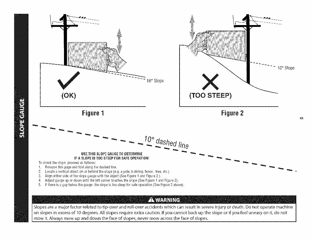
6.
8.
Installthebagsontothemountingframeasshownin Figure5.Simplyplace
theleadingedgeof thebagontothefront framerail, thenrockthebag
backwardsanddownintoplace.Repeatforthesecondbag.
FigureS
Removethedischargechute,ormulchplug.Retainthewingknobsfor
installationof deckchutein step10.
Insertthechutetubethroughthegrass-catcherhood,in theopening
provided.It iseasiestto feedtheendofthetubeinto theopeningwith the
chutetubeflippedupsidedown,then rotatingright-sideonceinsertedinto
thehood.SeeFigure6.
9. Mountthebaggerchutetubeto thedeckofthetractorbyloweringthechute
tubeoverthemountingboltsinthemowingdeck,asshownin Figure7.
10. Securetherearmountingboltwith awing knob(1),thenthefrontmounting
boltwith anotherwingknob(2)asshowninFigure7.
Figure7
\
Figure6
9

Assembliagand Installiag the Counter-Weight
Assemble,thenattachthecounter-weightto thefrontsteeringassemblyusingthe
hardwarein pack683-05063,asshownin Figure8andFigure10.
1. Installthecounter-weightmountingbracketto thecounter-weightusing
two 710-0572carriagebolts,two 736-0159flat washersandtwo 712-04063
flangelocknutsfrom hardwarepack683-05063.SeeFigure8.
@
Securetheweightbarassemblyto thetractorusingtwo 710-0378hex
bolts,two 736-0159flat washersandtwo 712-04063flangelocknutsfrom
hardwarepack683-05063.
Note:Usethetopholeson thetractorframe.
Figure8
Removethebumperfromthetractorbyremovingthetwo tapscrewsthat
secureit, asshownin Figure9.
Note:Thebumpermayberetainedfor laterusein thecaseinwhichthe
baggerisremoved.
o
Figure9
10
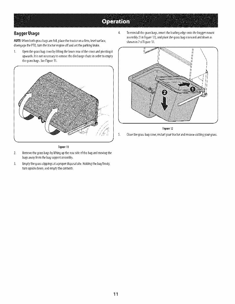
BaggerUsage
NOTE:Whenbothgrassbagsarefull, placethetractoronafirm, levelsurface,
disengagethe PTO,turn thetractorengineoff andsettheparkingbrake.
1. Openthegrassbagcoverbylifting thelowerrearofthecoverandpivotingit
upwards.It isnotnecessaryto removethedischargechuteinorderto empty
thegrassbags.SeeFigure11.
Toreinstallthegrassbags,insertthe leadingedgeontothebaggermount
assembly(1 inFigure12),andpivotthegrassbagrearwardanddownas
shownin2of Figure12.
Figure12
5. Closethegrassbagcover,restartyourtractorandresumecuttingyourgrass.
Figure11
Removethegrassbagsbylifting uptherearsideofthe bagandmovingthe
bagsawayfromthebagsupportassembly.
Emptythegrassclippingsat aproperdisposalsite.Holdingthebagfirmly,
turn upsidedown,andemptythecontents.
11

13
@
12

!
Ref, I Part Number
1. 964-04167
2. 683-04771-0637
3. 683-04772-0637
4. 683-04775-0637
S. 683-04781A-0637
6. 710-0378
7. 710-0572
8. 710-3296
9. 712-04063
10. 712-04150
11. 720-04061
12. 926-0100
13. 731-09227
14. 731-09351
15. 735-0246A
16. 936-0159
17. 764-04148A
18. 783-08135-0637
Description
Grass Bag
Front Hood Assembly Frame
Rear Hood Assembly Frame
Bagger Support Assembly
Mounting Bracket
Hex Lock Screw, 5/16-18, 2.50
Carriage Bolt, 5/16-18, 2.50
Hex Head Screw, 1/4-20, .750
Flange Lock Nut, 5/16-18
Flange Lock Nut, 1/2-13
Knob, 3/8-16, .875
Push Cap, 3/8 Rod
Weight
Chute Tube
Plug End
Flat Washer, .349 x .879 x .063
Grass Catcher Hood
Weight Mounting Bracket
13

Garantia ........................................................................ 14
Medidas importantes de seguridad ............................. 15Gu_a pendiente de ........................................................ 17Contenido de la caja y paquetes de hardware ..............18Montaje e Instalaci6n ................................................... 20operaci6n de ............................................................... 23Lista de piezas ............................................................ 12
Craftsman Un ASo De Garantia
Duranteun aSodesdelafechadecompra,esteproductoest&garantizadocontracualquierdefectode materialeso manode obra. Unproductodefectuososer&reemplazadodeformagratuita.
Paralos detallesde lacoberturadegarantiaparaobtenerunreemplazogratis,visite el sitioweb:www.craftsman.com
Estagarantianocubre lasasambleasdel recogedorde cesped,que sonpiezasfungiblesquese desgastendebidoal uso normaldentrodel periododegarantia.
Estagarantiaes inv&lidasi esteproductose utilizamientrasquela prestaci6nde servicioscomercialeso si se alquilaa otra persona.
Estagarantiale otorgaderechoslegalesespecificos,y ustedtambi_npuedetenerotrosderechosquevariandeestadoa estado.
Sears Brands Management Corporation, Hoffman Estates, IL 60179
© SearsBrands,LLC 14

Lapresenciadeeste sirnboloindicaque setratade instruccionesirnportantesde seguridadquese debenrespetarparaevitarponerenpeligrosu seguridadpersonaly/o materialy lade otraspersonas.Leay siga todaslas instruccionesdeestemanualantesde poneren funcionarnientoestarn_quina.Si no respetaestasinstruccionespodriaprovocarlesionespersonales.Cuandoveaestesirnbolo,ipresteatenci6na la advertencia!
PROPOSICION 65 DE CALIFORNIA
Elescapedel motordeesteproducto,algunosde suscornponentesy algunoscornponentesdelvehiculocontieneno liberansustanciasquirnicasqueelestadodeCaliforniaconsideraque puedenproducirc_ncer,defectosde nacirnientouotrosproblernasreproductivos.Losbornesdela bateriay los accesoriosalinescontienenplornoycornpuestosde plorno,sustanciasquirnicasque segOnIo estableci-do pot el Estadode Californiacausanc_ncery da_osenel sisternareproductivo.Ldveselas manos despu_sde estaren contactocon estoscomponentes.
Estarn&quinarueconstruidaparaseroperadadeacuerdoconlas reglasde seguridadcontenidasenestemanual.AI igualqueconcualquiertipo deequipornotorizado,undescuidoo errorporpartedeloperadorpuedeproducirlesionesgraves.Estarn&quinaes capazde arnputarrnanosy piesy dearrojarobjetoscon granfuerza.Deno respetarlas instruccionesde seguridadsiguientessepuedenproducirlesionesgraveso larnuerte.
Su responsabilidad--Restrinja el usode estarn_quinarnotorizadaa las personasque lean,cornprendany respetenlasadvertenciase instruccionesqueaparecenen estemanualyen larn_quina.
iGUARDEESTASINSTRUCCIONES!
Fundonamiento general
1. Lea, comprenda y respete todas las instrucciones que figuranen el equipo yen los manuales antes de intentar armarlo yhacerlo funcionar. Guarde este manual en un lugar seguropara consultas futuras y peri6dicas, asi como para solicitarrepuestos.
2. Para ayudar a evitar una lesi6n pot contacto con las cuchillaso con un objeto que sea arrojado, mantenga alas personasque observan, a los ayudantes, ni_os y mascotas alejados a nomenos de 25 metros de la m_quina mientras est& funcionando.Detenga la m&quina si alguien entra en la zona.
3. Revise minuciosamente el _irea donde se va a usar el equipo.Retire todas las piedras, palos, cables, huesos, juguetes y otrosobjetos extra_os que podrian set recogidos y arrojados por laacci6n de las cuchillas. Los objetos arrojados por la m&quinapueden causar lesiones graves.
4. Para protegerse los ojos, utilice siempre galas o lentes deseguridad mientras opera la m&quina o mientras la ajustao repara. Los objetos arrojados que rebotan pueden causarlesiones oculares graves.
5. Nunca opere la cortadora de c_sped sin tenet bien colocadala cubierta de descarga o el colector de c6sped. Si falta o
est_ da_ada la cubierta de descarga oun componente delaccesorio embolsador puede resultar en lesiones por contacto
con la cuchilla o con objetos arrojados.
6. No ponga las manos ni los pies cerca de las piezas rotatorias nidebajo de la plataforma de corte. El contacto con las cuchillaspuede resultar en la amputaci6n de una mano o pie.
7. Apague el motor de la cortadora de c_sped y espere quelas cuchillas se detengan totalmente antes de desbloquearla abertura de descarga de la cortadora o las piezas de laembolsadora.
8. Reduzca la velocidad antes de girar. Opere la m&quina de
forma pareja. Evite el funcionamiento err_itico y la velocidadexcesiva. Tenga en cuenta que el accesorio colector de c6sped
puede afectar las caracteristicas de manejo de su cortadora.
Fundonamiento en pendientes
Las pendientes son un factor importante en los accidentes
ocasionados pot p_rdida de control y vuelcos que pueden causarlesiones graves e incluso la muerte. Los accesorios tambien puedenafectar la estabilidad de la m&quina. La operaci6n en pendiente
requiere mayor precauci6n.
Para seguridad, use el medidor de pendientes que se incluye comoparte de este manual para estimar el _ingulo de la pendiente antesde hacer funcionar la m_iquina en una zona inclinada. Si la pendiente
es mayor a 10 grados en el medidor, no opere la cortadora con elaccesorio embolsador en ese sector, pues podria causar lesiones
graves.
I-lagaIosiguiente:
1. Corte hacia arriba y abajo de las pendientes, no en formatransversal. Tenga sumo cuidado al cambiar de direcci6n enuna pendiente.
2. Est_ atento a los hoyos, surcos, baches, rocas, u otros objetosocultos. El terreno desnivelado puede voltear la m&quina. Elpasto alto puede ocultar obst_iculos.
3. Conduzca a baja velocidad. Elija una velocidad Iosuficientemente baja como para no tener que detenerseo cambiar de marcha mientras est,1 en la pendiente. Losneum_ticos pueden perder tracci6n en las pendientes auncuando los frenos funcionen correctamente. Mantengala m&quina siempre en velocidad cuando desciende unapendiente, para poder frenar con el motor.
15
4. Siga las recomendaciones del fabricante sobre pesos ycontrapesos de las ruedas, para mejorar la estabilidad.
5. Haga que todos los movimientos en las pendientes seanlentos y graduales. No cambie repentinamente la velocidadni la direcci6n. Un frenado o cambio de velocidad repentinospueden causar que el frente de la m_quina se levante y d6 unavoltereta hacia atr_s, Io que podria causar lesiones graves.
6. Evite arrancar o detenerse en una pendiente. Si los neum_ticospierden tracci6n, desenganche las cuchillas y desciendalentamente la pendiente.
No haga I0siguiente:
I. No gire en una pendiente a menos que sea imprescindible. De
ser posible, gire lenta y gradualmente cuesta abajo.
2. No corte el c_sped cerca de barrancos, zanjas o terraplenes. Lacortadora de c_sped podria volcarse repentinamente si una de
las ruedas estuviera sobre el borde de un acantilado o zanja, osi un borde se desmoronara.
3. No intente estabilizar la m_quina poniendo el pie en el suelo.
4. No utilice un colector de c_sped en pendientes empinadas.
5. No corte el c_sped humedo. Una reducci6n en tracci6n puede
causar derrapes.
Servki0 general
I. Antes de limpiar, reparar o inspeccionar la m_quina,
compruebe que las cuchillas y todas las piezas m6viles se
hayan detenido. Desconecte el cable de la bujia y p6ngalohaciendo masa contra el motor para evitar que arranqueaccidentalmente.
2. Mantenga todas las tuercas, pernos y tornillos bien ajustados
para asegurarse de que el equipo est_ en condiciones seguras
de operaci6n.
3. Nunca intente violar el sistema de bloqueo de seguridad u
otros mecanismos de seguridad de la cortadora. Controle
peri6dicamente que funcionan correctamente.
4. No intente nunca hacer ajustes o reparaciones a la cortadoramientras el motor est_ en marcha.
5. Los componentes del colector de c6sped y la cubierta de
descarga est_n sujetos a desgaste y daffos que podrian dejarexpuestas piezas que se mueven o permitir que se arrojen
objetos. Para proteger su seguridad, verifique frecuentemente
todos los componentes y reempl_celos inmediatamente0nicamente con piezas de los fabricantes del equipo original
(O.E.M.) indicados en este manual. El uso de piezas que no
cumplen con las especificaciones del equipo original puede
resultar en rendimiento inadecuado y puede poner en peligro
la seguridad.
6. Mantenga o reemplace las etiquetas de seguridad y deinstrucciones segun sea necesario.
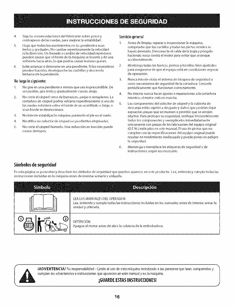
Simbolosde seguridad
En esta p_gina se presentan y describen los simbolos de seguridad que pueden aparecer en este producto. Lea, entienda y cumpla todas las
instrucciones incluidas en la m_quina antes de intentar armarla y utilizarla.
LEA LOS MANUALES DEL OPERADOR
Lea, entienda y cumpla todas las instrucciones incluidas en los manuales antes de intentar armar la
unidad y utilizarla.
DETENCION
Apague el motor antes de abrir la cubierta de la embolsadora.
IADVERTENCIA! Su responsabilidad--Limiteel uso deestam_.quinamotorizadaa las personasquelean,comprendanycumplanlasadvertenciase instruccionesqueapareceneneste manualy en lam_.quina.
iGLIARDEESTASINSTRL!CCIONES!
16
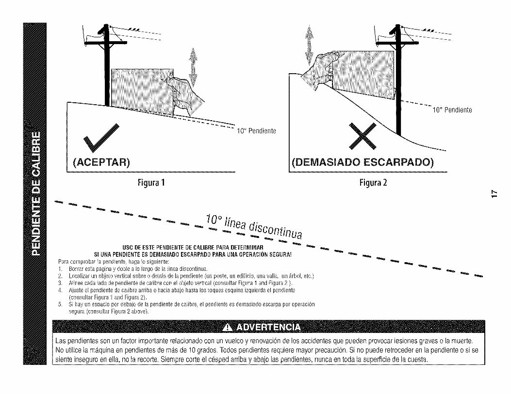
(ACEPTAR)
Figura1
"" 10° Pendiente
10° Pendiente
(DEiVIASlADO ESCARPADO)
Figura2
0oI[nea- - " "" - _ .-...diSC°ntinua
US0 DEESTEPENDIENTEDECALIBREPARADETERiVIINARSI UNAPENDiENTEESDEIV1ASiADOESCARPADOPARAUNAOPERACi(_NSEGURA!
Paracomprobarlapendiente,hagaIosiguiente:1. Borrarestap_.ginay dobleaIo largodela lineadiscontinua.2.3.4.
Localizarun objetoverticalsobreo detrJ.sdelapendiente(unposte,unedificio,unavalla, un _.rbol,etc.)Alineecadaladodependientedecalibrecon elobjetovertical(consultarFigura1 andFigura2 ).Ajusteel pendientedecalibrearribao haciaabajohastalos toquesesquinaizquierdael pendiente(consultarFigura1andFigura2).Sihayun espaciopordebajodela pendientedecalibre,el pendientees demasiadoescarpaporoperaciOnsegura(consultarFigura2 above).
Las pendientesson un factor importante relacionadocon un vuelco y renovaci6nde los accidentesque pueden provocar lesionesgraves o la muerte.No utilice la m_.quinaen pendientes de m_.sde 10grados. Todos pendientesrequiere mayorprecauci6n.Si no puede retroceder en la pendiente o si sesiente inseguro en ella, no la recorte. Siempre corte el cesped arriba y abajo laspendientes, nunca en toda la superficiede la cuesta.

Antesdecomenzarla instalaci6n,quitetodaslas piezasde lacaja paraasegurarsedeque todoest,.presente.Contenidosde cart6nseenumerana continuaci6ny se muestraa continuaci6n.Unpaquetedehardwarese incluyeenestekity se detallaenla p_.ginasiguiente.
o
o
o
o
o
Dos conjuntos de bolsa de hierba
Campana de recogedor de hierbaTubo de conducto
Saco de soporte
Soporte de montaje
o
o
o
Peso del contador
Soporte de montaje de peso de contador
U.np.aquete de Hardware (detallados en la pdginaslgulente)
f
18
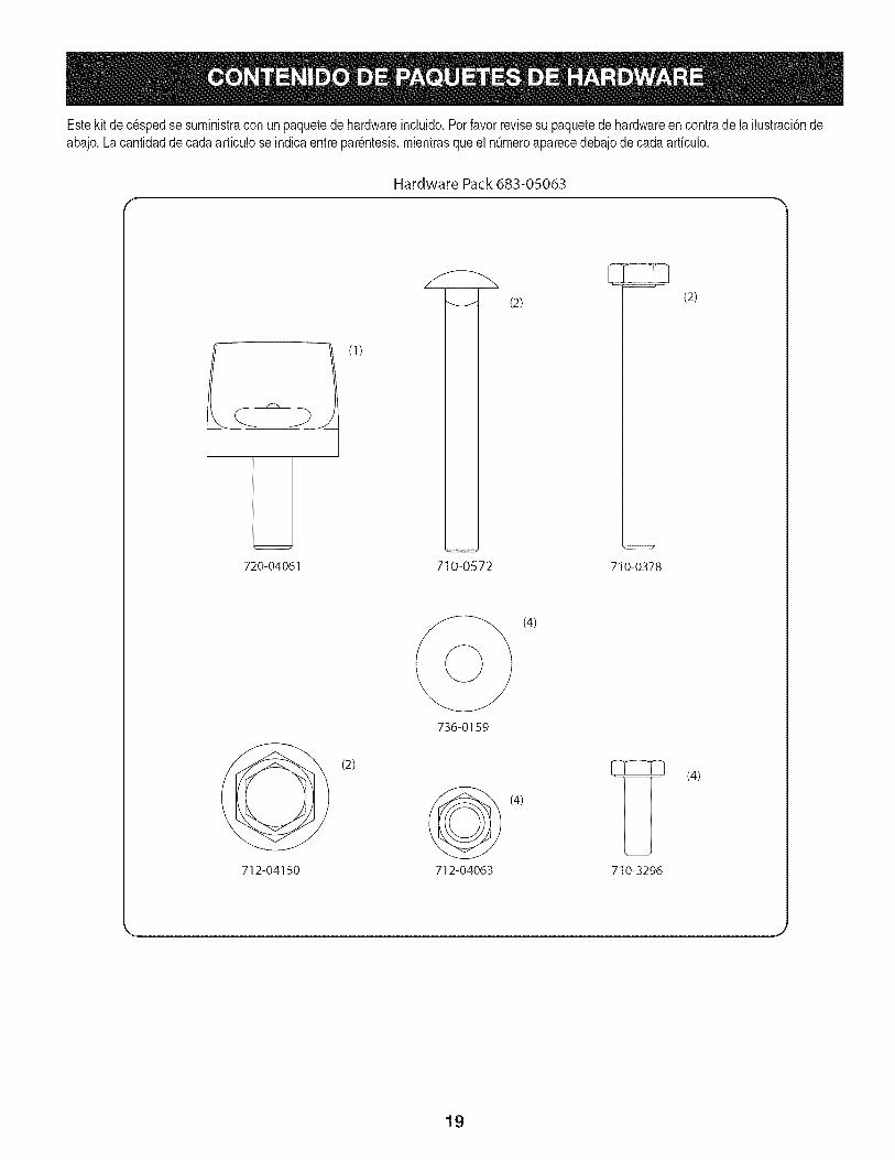
Estekit decespedse suministracon unpaquetede hardwareincluido.Por favorrevisesu paquetede hardwareen contrade la ilustraci6ndeabajo. Lacantidadde cadaarticulose indicaentre par_ntesis,mientrasqueel nQmeroaparecedebajode cadaarticulo.
Hardware Pack 683-05063
L720-04061
(1)
710-0572
(2)
710-0378
(2)
_/ (2)
712-04150
736-0159
712-04063
(4)
(4)
710-3296
(4)
19

Instalaci6ndeiconjunto deia embolsadora 3.
Afin deinstalarlam_nsuladesoportedelaembolsadora,sigaestospasos:
1. Extraigaydesecheloscuatropernosautorroscantesdelbastidortraserodel 4.
tractor,comoseindicaenlaFigura1.
/
Figure1
Instalela m_nsuladesoportedelaembolsadoraenel tractorconloscuatro
pernoshexagonales710-3015del paquetedeelementosdeferreteria683-
05063.Pasecadaunodelospernoshexagonalesporelbastidordeltractor,
el tubodemontajedelatapatraserayenr6squelosen latuercadesoldadura
delam_nsuladesoportedelaembolsadora,comoseindicaenla Figura2.
i
Figure2
Coloqueelconjuntodemontajede labolsarecolectoradec_spedsobrela
m_nsuladesoportede laembolsadorabaj_ndola(1)ycolocandoelconjunto
enlaranuraprovistaenlam_nsulasoporte.Veael recuadrode laFigura3.
Sujeteelconjuntodemontajedelaboisarecolectoradec_spedalam_nsulade
soportedelaembolsadoraconlaperilladesujed6n(720-04061)queseencuentra
enelpaquetedeelementosdeferreter[a(683-05063).Consuite(2)enlaFigura3.
Figure3
Extraigalastapasdeprotecci6ndelasroscasdemontajedelatapadelacubierta
delaembolsadoraycoloquelacubiertadelaembolsadorasobreelconjunto
demontajedelaboisaderecolecd6ndec_spedcomoseindicaenlaFigura4.
Sedebenalinearlasleng_etasdelatapadentrodelasranurasdelconjuntode
montajedelabolsarecolectoradec_sped.Sujetelacubiertadelaembolsadora
condostuercasdeseguridadconbrida(712-04150)queseincluyenenelmismo
paquetedeelementosdeferreter[a.
Figure4
2O

6,
7.
8.
Coloquelasbolsassobreelbastidordemontajecomoseindicaenla Figura
5.%1odebecolocarel bordeentrantedelabolsasobrelaguiadelbastidor
frontal,luegobalanceelabolsahadaatr,_syhadaabajoparaquequedeen
posid6n.RepitaIomlsmoparalasegundabolsa.
Figure5
Retireel tubodedescarga,o clavijadeabono.Conservelospomosde
mariposaparala instalad6ndelconductodecublertaenel paso10.
Inserteel tubodelcanala trav_sdelatapadelcolectordec_sped,en la
aberturaprovlsta.Resultam_sfl_cilsiseintroduceelextremodeltubodentro
delaaberturaconeltubodel canalgiradodemaneraquequededadovuelta,
girandoluegoa laderechadespu_sdeinsertarloenlatapa.VealaFigura6.
9. Monteel tubodelcanaldelaembolsadoraen laplataformadeltractor
bajandoeltubodelcanalsobrelospemosdemontajede laplataformade
corte,comoseindicaenla Figura7.
10. Sujeteelpemodemontajetraseroconunaperllladealeta(1),luegoel
pemodemontajedelanteroconotra perilladealeta(2),comose[ndlca
enla Figura7.
Figure7
Figure6
21
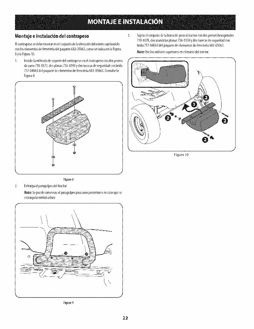
Montaje e instalaci6n dei contrapeso
Elcontrapesosedebemontarenelconjuntodeladirecddndelanterosujet_ndolo
conloselementosdeferreteriadel paquete683-05063,comoseindicaenla Figura
8y laFiguraI0.
I. Instalela m_nsuladesoportedelcontrapesoenelcontrapesocondospernos
decarro710-0572,dosplanas736-0159ydostuercasdeseguridadconbrida
712-04063delpaquetedeelementosde ferreteria683-05063.Consultela
Figura8.
I
Sujeteelconjuntode labarradepesoaltractorcondospernoshexagonales
710-0378,dosarandelasplanas736-0159ydostuercasdeseguridadcon
brida712-04063del paquetedeelementosdeferreteria683-05063.
Nora: Uselosorificiossuperioresenel marcodeltractor.
0
Figure 10
Figure8
Extraigaelparagolpesdeltractor.
Not:a:Sepuedeconservarel paragolpesparausosposterioresencasoquese
extraigalaembolsadora
o
Figure9
22

Usode ia embolsadora
NOTA:Unavezqueest_nllenasambasbolsarecolectorasdec_sped,coloqueel
tractorensuelofirme ynivelado,desactivelaPTO,apagueelmotordel tractory
pongaelfrenodemano.
I. Abralacubiertade labolsarecolectoradec_spedlevantandolapartetrasera
inferiorde lacubiertaygir_ndolahaciaarriba.Noesnecesarioquitarelcanal
dedescargaa fin devadarlasbolsasrecolectorasdec_sped.VealaFigura11.
Figure11
Extralgalasbolsasrecolectorasdec_spedlevantandolapartetraseradela
bolsayalejandolasbolsasdelconjuntodesoportedelasbolsas.
Vacielosrecortesdec_spedenun lugaradecuadoparadesecharlos.
Sosteniendolabolsaconfirmeza,d_lavueltay vacieelcontenido.
Paravolvera [nstalarlasbolsasrecolectorasdec_sped,[nserteel borde
entranteenelconjuntodemontajedelaembolsadora(I delaFlgura12)y
girelabolsarecolectoradec_spedhadaatr_syabajocomoselndlcaen2 de
laFigura12.
Figure12
5. Cierrelacubiertade labolsarecolectoradec_sped,reinideeltractory
retomeelcortedelc_sped.
23

Thispageintentionallyleftblank.
24