Embed Size (px)
Citation preview

Owner’s ManualBedienungsanleitung
Mode d’emploi

1
CongratulationsThank you for purchasing the Yamaha B1D Divided Pickup Unit.
The B1D Divided Pickup Unit can pick up the vibrations produced byan electric bass guitar’s strings, and transmit those signals to a YamahaGuitar MIDI Converter (G50). When properly installed and adjusted itcan convert almost any steel stringed bass guitar into a controller for aguitar synthesizer system. It can be used on normal 4-string basses aswell as 5-string, and 6-string basses.
To get the most out of your B1D, please read this owner’s manualcarefully, and follow the installation instructions within, in order to en-sure proper operation. Also, keep this manual in a safe place for futurereference.
■ FeaturesAs well as any normal 4-string electric bass, theunit can also be used on 5-string, and 6-stringbasses. A number of installation options areprovided to allow for different guitar shapes, use,and playing styles. Choose a method that bestsuits your bass and playing requirements.
Methods for Attaching the Divided Pickup:Special Fittings (removable), double-sidedadhesive tape, screw.
Methods for Attaching the Controller:Velcro fastener, bracket, double-sidedadhesive tape, screw.
• One touch operation allows you to switchbetween bass synthesizer sound and bassguitar sound. Also, the synthesizer’s voiceand bass guitar’s signal can be outputseparately or together, offering a widevariety of sounds for added playing enjoy-ment.
• Of course, the bass synthesizer’s volume canbe controlled. But you can also control otherfunctions like octave, parameter values,program changes (that are transmitted fromthe G50’s memory), and G50’s memorynumbers (which can be changed by a valueof +1/-1).
Contents
Eng
lish
Precautions ....................................... 2
Nomenclature & Functions ................ 3
Parts List ........................................... 4
Before You Install ............................... 5
Attaching the Divided Pickup ............ 6
Attaching the Controller ................... 11
Connections .................................... 13
G50 Settings ................................... 14
Controller & Switch.......................... 15
Getting the Most Out of YourB1D & G50 ...................................... 16
Troubleshooting ............................... 17
Specifications .................................. 18
2
■ LocationDo not expose the B1D to the following condi-tions to avoid deformation, discoloration, or moreserious damage.
• Direct sunlight (e.g. near a window). • High temperatures (e.g. near a heat source,
outside, or in a car during the daytime). • Excessive humidity. • Excessive dust. • Strong vibration.
■ Connections• When connecting the B1D to the Yamaha G50
Guitar MIDI Converter, be sure to use thespecified multi-pin cable (supplied with theG50 Guitar MIDI Converter).
• Always connect the direct guitar cable (page4), even if you don’t intend to use the directguitar sound. The direct guitar cable isessential for proper grounding, to minimizenoise and prevent electric shock.
• Always unplug cables by gripping the plugfirmly, not by pulling on the cable.
• Disconnect all cables before moving theinstrument or any connected equipment.
■ Handling and Transport• Never apply excessive force to the controls,
connectors or other parts of the instrument. • Physical shocks caused by dropping, bump-
ing, or placing heavy objects on the instru-ment can result in scratches and more seriousdamage.
• Be careful not to damage the B1D controllerwhen placing the guitar in a case or on astand.
Precautions !! PLEASE READ THIS BEFORE PROCEEDING !!␣
Yamaha is not responsible for damage caused by improper installation, handling, or operation.
■ Cleaning • Clean the unit with a dry soft cloth. • A slightly damp cloth may be used to remove
stubborn grime and dirt. • Never use cleaners such as thinner.
■ Notes on Adhesive Tape • Depending on the surface of the bass guitar the
finish may peel off or be altered chemicallywhen the pickup/controller is mounted usingadhesive tape (double-sided). To make sure, itis recommended that you first try this methodof attachment by applying some tape at a placeon the guitar body which is not visible nor-mally.
• If the pickup must be removed from the base guitar,always use a fresh layer of double-sided adhesivetape and/or cushion when reinstalling, as theadhesive properties of used tape/cushion are reduceddrastically when peeled off the mating surface. Also,before attaching the adhesive tape or pickup, cleanthe mating surface thoroughly, as dust and greasemay cause the pickup to come loose.
■ Service and Modification • The B1D contains no user serviceable parts.
Opening it or tampering with it in any way canlead to irreparable damage and possibly electricshock. Refer all servicing to qualifiedYAMAHA personnel.

3
q
t
r
e
w
y
u
i
q Divided PickupThis magnetic type pickup converts vibrationsfrom the bass guitar’s individual strings into anelectrical signal.The pickup is attached to the bass guitar’s body.
→ page 6 “Attaching the Divided Pickup”
w Synth Volume ControlControls the volume of the synthesizer.
* Does not adjust the volume of the bass guitar.
e Power IndicatorThe B1D is receiving power from the G50 GuitarMIDI Converter when this indicator is lit. Theindicator lights when the B1D is properly con-nected to the G50 via the 13-pin cable.
r Direct Bass Guitar Input JackThis jack allows the B1D to receive the combinedoutput from the bass guitar’s normal pickups (bassguitar signal) from the guitar’s output jack. Use thesupplied direct bass guitar signal cable whenmaking connections.The bass guitar signal is output from the GUITARDIRECT OUT jack of the G50 (→ pg. 13).
t B1D Output JackThe selected signal from the Output Selector istransmitted to the Guitar MIDI Converter via thisjack.
y Output Selector (BASS/MIX/SYNTH)Selects the type of output to be delivered via the13-pin cable connector to the Guitar MIDI Con-verter.
BASS: Only the direct bass sound (output fromthe electric bass pickup) will be heard.
SYNTH: Only the synthesizer sound (output fromthe divided pickup) will be heard.
MIX: Both the direct bass guitar signal and thesynthesizer sounds will be heard.
u UP Switch
i DOWN SwitchAccording to settings in the Guitar MIDI Con-verter, these switches can be used to increase ordecrease the values by 1 for program memorynumbers, parameter values, program changenumbers, octave shift values, etc.→ Refer to the manual for your Guitar MIDI
Converter for further information.* G50 owner’s manual: pg. 12
Nomenclature & Functions
Divided Pickup
Controller

4
● B1D Main Unit(Divided Pickup + Controller)
Parts List
Before you install the B1D, please make sure you have all of the parts listed below.
● Direct Bass Guitar Cable ● Clearance Gauge................. 2 Pieces
● Divided Pickup Attachment Parts
• Bracket ................. 1
• Spacer A (Thickness: 1mm)............... 10 Pieces
• Spacer B (Thickness: 0.3mm)............... 12 Pieces
• Pickup Cushion(Double-Sided Adhesive)................. 8 Pieces
• Pickup Double-Sided Adhesive Tape............... 16 Pieces
• Springs ..... 2 Pieces • Tapping Screws 3x25mm ............. 2Used to attach the pickup to the body.
• Small Screws3x6mm, with washer .................. 2Used to attach the pickup fittings to thebase plate.
• Small Screws3x6, 3x8, 3x10, 3x12mm .. 2 eachUsed to attach the pickup to the pickupfittings.
• Plate Tapping Screws3x10mm, 1 type .............. 2 piecesUsed to attach the base plate to the bassbody.
• Base Plate (Right, Left) ....... 1 Set • Double-Sided Adhesive Tape forBase Plate ..................... 8 Pieces
• Pickup Attachment Fittings(Right, Left) .......................... 1 Set
● Controller Attachment Parts
• Velcro Fastener .... 1 • Suction Cups ................. 3 Pieces
• Tapping Screw3x16mm ............... 1Used to attach the controller to thebody.
• Controller Cushion(Double Sided-Adhesive Tape)................. 6 Pieces

5
■ Installing on the Bass GuitarBefore you install the B1D on your bassguitar, carefully read the advice providedbelow. Select an installation methodwhich is best suited to your bass guitarand playing requirements.
● Select the Method of InstallationThree methods for installing the divided pickupare listed below.
● Base Plate Installation (Removable)• Height adjustment is easily performed.• The divided pickup can easily be removed yet
pickup height adjustment is maintained.
● Double-sided Adhesive Tape• Reduces the risk of damaging the bass guitar body.• More time and care must be taken to achieve proper
pickup height.
● Spring and Screw Installation• Height adjustment is easily performed.• The pickup can be securely attached to the bass
body.• It will be necessary to drill holes in the bass
guitar’s body.
Five methods for installing the Controller unitare listed below.
● Velcro Installation• Easy removal and replacement.
● Bracket Installation• Used in conjunction with adhesive tape, the control-
ler can be installed on bodies that are not flat.• The bracket can also be attached using the bass
guitar’s strap pin. However, some caution must beused to keep from damaging the strap pin screw.
● Suction Cup Installation• Easy to remove, replace and transport the unit.• Easy to attach the controller unit to a bass guitar
with a flat top and a smooth, shiny finish.
● Double-sided Adhesive Tape• Easy and secure attachment is possible.
● Screw Installation• Used in conjunction with adhesive tape, the control-
ler can be installed on bodies that are not flat.• It will be necessary to drill a hole in the bass
guitar body.
* If you use the base plate attachment (remov-able) for the divided pickup, it is a good ideato attach the controller with Velcro tape orsuctions cups so it is removable as well.
Before You Install
● The Bass GuitarThe B1D is a divided pickup designed for use withsteel string electric basses. It can be used with 4-string as well as 5- and 6-string basses. If your bassguitar is one of the types listed below, the B1D willnot function properly with it.
• 8-string basses or other non-standard stringconfigurations other than 4-, 5-, and 6- stringbasses.
• Nylon string or other non-metallic string bassguitars.
• Basses with extremely wide or narrow stringspacing. Any bass guitar that the strings will notproperly fit over the magnetic pickup (→ refer to“Specifications” on pg. 18).
• Basses with extremely low string clearance.Depending upon the manner in which the pickup isattached, make sure that there is more than10-13mm (0.39"-0.51") of clearance.
The divided pickup is specially designedand adjusted for use on bass guitars withup to 6-strings, the pickup will not func-tion with 6-string guitars.
The divided pickup should be attached between thebridge and rear pickup, ideally 10-20mm (0.39"-0.79") from the bridge. Make sure you have ad-equate space for proper installation of the pickup.
Make sure your bass’ neck (truss rod) and stringheight/intonation (bridge) are properly adjustedbefore installing the B1D.
Disconnect the Direct Bass Guitar Signalcable and the 13-pin cable from the B1Dcontroller before installation.
Installing the Pickup ControllerDue to the divided pickup’s magnetic strength, thedouble-sided tape may peel off the bass guitar body ifthe point of attachment is weak. Also, the pickup andcontroller may be knocked off, if the bass guitar is
subject to strong shock or prolonged use, if anattachment method other than screw installation isused. Select a method of attachment according toinstallation position, and the strengths of the methodof installation.

6
NGOK OK
E A D G
B E A D G
E A D G C
B E A D G C
■ Mark the Installation positionfor the divided Pickup.
The divided pickup should be located between therear pickup and bridge so that the cable end of thepickup is oriented toward the lower bass string (thepickup will not function if it is attached facing theopposite direction).The divided pickup is designed for use on basseswith up to 6 strings (6B, 5E, 4A, 3D, 2G, 1C). If thepickup is to be used on a 4-string bass, align the 4magnetic yokes, in the center portion of the pickup,with the strings.For 5-string basses with a [B, E, A, D, G] tuning,use the 5 magnetic yokes on the cable end of thepickup. If the tuning is [E, A, D, G, C] use the 5magnetic yokes opposite the cable end of thepickup.
• For 4-string basses (4E, 3A, 2D, 1G)
Place the divided pickup on the body and decidethe optimum position for installation.From the low end string side, slide the dividedpickup under the bass guitar strings. Using themagnetic attraction of the pickup to the strings,adjust the position so that each string passes overits corresponding magnetic yoke.
Attaching the Divided Pickup
StringPickup’s Magnetic Yokes
Rear Pickup
Adjust the position of the pickup so that it meets theconditions listed below.
1. Each string must pass over its correspondingmagnet.The pickup will not function properly if thestring does not properly pass over the magneticyoke. Check that the strings pass over themagnetic yokes, even when bending the strings.
2. The distance between the divided pickupand the bridge should be about 10-20mm(0.39"-0.79").
* Make sure the pickup is not in contact withthe bridge.
* The distance can be increased to more than20mm (0.79") as long as the strings pass overthe magnetic yokes when bending the strings.
Divided Pickup
Bridge
10-20mm(0.39"-0.79")
• For 5-string basses (5B, 4E, 3A, 2D, 1G)
• For 5-string basses (5E, 4A, 3D, 2G, 1C)
• For 6-string basses (6B, 5E, 4A, 3D, 2G, 1C)
3. String height should not be widely varied.Extreme variations in string height will resultin a poor output level for the pickup (Theoutput level can be somewhat controlled withthe G50’s Gain Setting).

7
Once the optimum installation position hasbeen decided, you can prepare to attach thepickup. However, the distance between thestring and the pickup’s magnetic yoke is ex-tremely important.Since the height of the pickup’s magnetic yokescannot be adjusted individually, the pickup posi-tion, the pickup’s overall height, and string height,can be adjusted to meet the conditions necessaryfor optimum string/pickup clearance.The distance between the top of the pickup’smagnetic yokes and the bottom of each stringshould be about 1-2mm (0.04"-0.08") when eachstring is fretted at the highest note on the neck. Thedistance between the pickup and the bottom of thestrings can be set to less than 1mm (0.04") as longas the strings do not touch the pickup when thebass is played. However, as long as other stringscan be set to a height of 2.0mm (0.08") or less, tryto set the E and B strings between 1.5 (0.06") and2.0mm (0.08").Also, the output level for each of the magneticpickups is fairly different so after the dividedpickup has been attached make sure you set InputGain each strings with the Guitar MIDI Converter.
The chart below lists the optimum string/pickupdistance and G50 Input Gain Settings for averagebass guitars. Use the chart as a reference whensetting up your pickup.
* For 4-string basses(looking from the bridge side).
Distance *1 Gain Setting *2
4-string bass G string 1.0mm (0.04") 15D string 2.0mm (0.08") 30A string 2.0mm (0.08") 30E string 1.5mm (0.06") 10
5-string bass G string 1.0mm (0.04") 15D string 1.0mm (0.04") 15A string 1.5mm (0.06") 22E string 2.0mm (0.08") 20B string 1.0mm (0.04") 6
6-string bass C string 1.0mm (0.04") 15G string 1.5mm (0.06") 22D string 1.0mm (0.04") 15A string 1.0mm (0.04") 15E string 2.0mm (0.08") 20B string 2.0mm (0.08") 10
*1 The distance between the string and magneticyoke when the string is fretted on its highestnote.
*2 The G50’s individual input gain settings (1-50).
Use the supplied clearance gauge (1mm (0.04")thick) to check pickup clearance. Put two gaugestogether to check for a clearance of 2mm (0.08").
■ First, make sure the truss rod and stringheight are properly adjusted, then tune thestrings to their normal pitch.
■ Determine the optimum method of attach-ing the divided pickup.Refer to the “Select the Method of Installa-tion” section on page 5, and determine theoptimum method of attachment in regards tothe attachment position, materials, type ofbody, playing requirements, etc.
■ Use the supplied suction cups to tempo-rarily attach the Controller to the body sothat it doesn’t get in the way while attach-ing the Divided Pickup.
Divided Pickup
E stringA string D string
G string1.5
(0.06")2.0
(0.08") 1.0 (0.04")2.0
(0.08")
Bass guitar body
Clearance gauge
20mm(0.08")1mm (0.04")
Attaching the Divided Pickup
Unit : mm (inch)
8
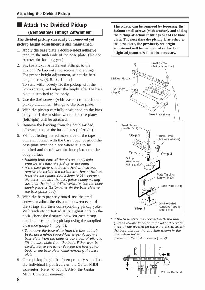
■ Attach the Divided Pickup(Removable) Fittings Attachment
The divided pickup can easily be removed yetpickup height adjustment is still maintained.
1. Apply the base plate’s double-sided adhesivetape, to the underside of the base plate. (Do notremove the backing yet.)
2. Fix the Pickup Attachment Fittings to theDivided Pickup with the screws and springs.For proper height adjustment, select the bestlength screw (6, 8, 10, 12mm).To start with, loosely fix the pickup with the6mm screws, and adjust the height after the baseplate is attached to the body.
3. Use the 3x6 screws (with washer) to attach thepickup attachment fittings to the base plate.
4. With the pickup carefully positioned on the bassbody, mark the position where the base plates(left/right) will be attached.
5. Remove the backing from the double-sidedadhesive tape on the base plates (left/right).
6. Without letting the adhesive side of the tapecome in contact with the bass body, position thebase plate over the place where it is to beattached and then lower the base plate onto thebody surface.* Holding both ends of the pickup, apply light
pressure to attach the pickup to the body.* If the base plate is to be attached with screws,
remove the pickup and pickup attachment fittingsfrom the base plate. Drill a 2mm (0.08”, approx).diameter hole into the bass guitar’s body makingsure that the hole is drilled vertically. Use the platetapping screws (3x10mm) to fix the base plate tothe bass guitar body.
7. With the bass properly tuned, use the smallscrews to adjust the distance between each ofthe strings and their corresponding pickup yoke.With each string fretted at its highest note on theneck, check the distance between each stringand its corresponding pickup using the suppliedclearance gauge (→ pg. 7).* To remove the base plate from the bass guitar’s
body, use a minus screwdriver to gently pry thebase plate from the body, or use a pair of pliers tolift the base plate from the body. Either way, becareful not to scratch or damage the bass guitarbody or the base plate while removing the baseplate.
8. Once pickup height has been properly set, adjustthe individual input levels on the Guitar MIDIConverter (Refer to pg. 14. Also, the GuitarMIDI Converter manual).
The pickup can be removed by loosening the3x6mm small screws (with washer), and slidingthe pickup attachment fittings out of the baseplate. The next time the pickup is attached tothe base plate, the previously set heightadjustment will be maintained so furtherheight adjustment will not be necessary.
Double-SidedAdhesive Tape forBase Plate
* If the base plate is in contact with the bassguitar’s volume knob or, removal and replace-ment of the divided pickup is hindered, attachthe base plate in the direction shown in theillustration below.Remove in the order shown (1→ 2).
Small Screw(3x6 with washer)
Base Plate(Right)
Base Plate (Left)
Small Screw(3x6/8/10/12)
Step 2 Small Screw(3x6 with washer)
Plate TappingScrew (3x10)
PickupAttachmentFitting (Left)
Base Plate (Left)
Step 1
Step 3
Volume Knob, etc.
Attaching the Divided Pickup
Spring
Divided Pickup
9
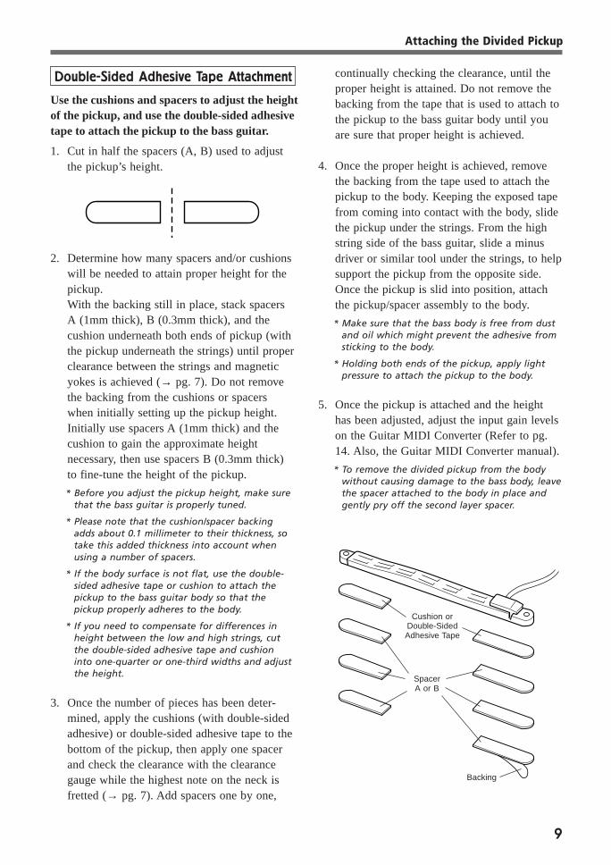
Double-Sided Adhesive Tape Attachment
2. Determine how many spacers and/or cushionswill be needed to attain proper height for thepickup.With the backing still in place, stack spacersA (1mm thick), B (0.3mm thick), and thecushion underneath both ends of pickup (withthe pickup underneath the strings) until properclearance between the strings and magneticyokes is achieved (→ pg. 7). Do not removethe backing from the cushions or spacerswhen initially setting up the pickup height.Initially use spacers A (1mm thick) and thecushion to gain the approximate heightnecessary, then use spacers B (0.3mm thick)to fine-tune the height of the pickup.
* Before you adjust the pickup height, make surethat the bass guitar is properly tuned.
* Please note that the cushion/spacer backingadds about 0.1 millimeter to their thickness, sotake this added thickness into account whenusing a number of spacers.
* If the body surface is not flat, use the double-sided adhesive tape or cushion to attach thepickup to the bass guitar body so that thepickup properly adheres to the body.
* If you need to compensate for differences inheight between the low and high strings, cutthe double-sided adhesive tape and cushioninto one-quarter or one-third widths and adjustthe height.
3. Once the number of pieces has been deter-mined, apply the cushions (with double-sidedadhesive) or double-sided adhesive tape to thebottom of the pickup, then apply one spacerand check the clearance with the clearancegauge while the highest note on the neck isfretted (→ pg. 7). Add spacers one by one,
continually checking the clearance, until theproper height is attained. Do not remove thebacking from the tape that is used to attach tothe pickup to the bass guitar body until youare sure that proper height is achieved.
4. Once the proper height is achieved, removethe backing from the tape used to attach thepickup to the body. Keeping the exposed tapefrom coming into contact with the body, slidethe pickup under the strings. From the highstring side of the bass guitar, slide a minusdriver or similar tool under the strings, to helpsupport the pickup from the opposite side.Once the pickup is slid into position, attachthe pickup/spacer assembly to the body.
* Make sure that the bass body is free from dustand oil which might prevent the adhesive fromsticking to the body.
* Holding both ends of the pickup, apply lightpressure to attach the pickup to the body.
5. Once the pickup is attached and the heighthas been adjusted, adjust the input gain levelson the Guitar MIDI Converter (Refer to pg.14. Also, the Guitar MIDI Converter manual).
* To remove the divided pickup from the bodywithout causing damage to the bass body, leavethe spacer attached to the body in place andgently pry off the second layer spacer.
Backing
Cushion orDouble-SidedAdhesive Tape
SpacerA or B
Attaching the Divided Pickup
Use the cushions and spacers to adjust the heightof the pickup, and use the double-sided adhesivetape to attach the pickup to the bass guitar.
1. Cut in half the spacers (A, B) used to adjustthe pickup’s height.
10
Use the following steps if you need to read-just the pickup height.
1. Determine the number of spacers you needto add or remove.
2. Remove only the pickup from the body.Without applying any excessive force tothe pickup, carefully pry the pickup fromthe spacers by sliding a thin, flat objectunder the low string end of the pickup,and gently lifting the pickup away fromthe spacer.
* Bending or twisting the pickup may causethe coil inside the pickup to snap, resultingin a damaged pickup. Use caution.
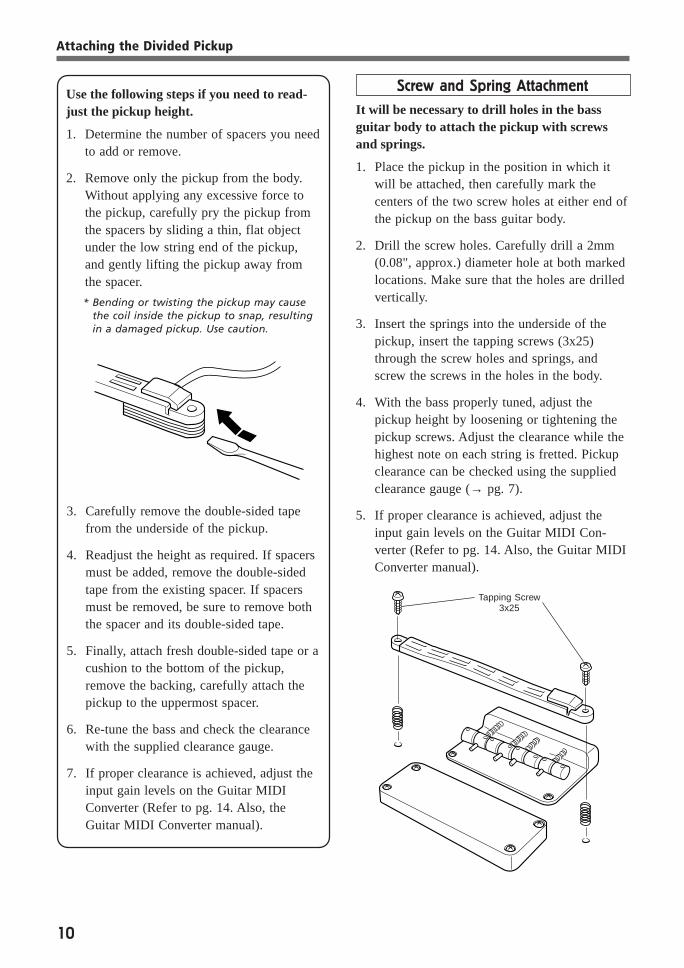
Screw and Spring Attachment
It will be necessary to drill holes in the bassguitar body to attach the pickup with screwsand springs.
1. Place the pickup in the position in which itwill be attached, then carefully mark thecenters of the two screw holes at either end ofthe pickup on the bass guitar body.
2. Drill the screw holes. Carefully drill a 2mm(0.08", approx.) diameter hole at both markedlocations. Make sure that the holes are drilledvertically.
3. Insert the springs into the underside of thepickup, insert the tapping screws (3x25)through the screw holes and springs, andscrew the screws in the holes in the body.
4. With the bass properly tuned, adjust thepickup height by loosening or tightening thepickup screws. Adjust the clearance while thehighest note on each string is fretted. Pickupclearance can be checked using the suppliedclearance gauge (→ pg. 7).
5. If proper clearance is achieved, adjust theinput gain levels on the Guitar MIDI Con-verter (Refer to pg. 14. Also, the Guitar MIDIConverter manual).
3. Carefully remove the double-sided tapefrom the underside of the pickup.
4. Readjust the height as required. If spacersmust be added, remove the double-sidedtape from the existing spacer. If spacersmust be removed, be sure to remove boththe spacer and its double-sided tape.
5. Finally, attach fresh double-sided tape or acushion to the bottom of the pickup,remove the backing, carefully attach thepickup to the uppermost spacer.
6. Re-tune the bass and check the clearancewith the supplied clearance gauge.
7. If proper clearance is achieved, adjust theinput gain levels on the Guitar MIDIConverter (Refer to pg. 14. Also, theGuitar MIDI Converter manual).
Tapping Screw3x25
Attaching the Divided Pickup
11
■ Decide the position forattaching the controller.
Consider the following points carefully whendeciding on the best location to install the controller.
• The controller and cable should not hinder perfor-mance.
• The controller should not block of hamper access toany of the bass guitar’s controls: volume, tone,switches, etc.
• The B1D controller should be positioned in aneasily accessible position.
• Do not position the controller in a manner that willapply excessive force to the cord that connects thedivided pickup and controller.
• Do not position the controller in a manner that willapply excessive force to the cord that connects thedirect bass guitar signal and controller.
• Do not position the controller in a manner that willapply excessive force on the controller or cordswhen the bass is placed on a guitar stand.
• Do not position the controller in a manner that willapply excessive force on the B1D or bass guitarwhen the bass is placed in its case.
■ Determine the optimum methodof attaching the controller.
Refer to the “Select the Method of Installation”section on page 5, and determine the optimummethod of attachment in regards to the attachmentposition, materials, type of body, playing require-ments, etc.Before you install the controller, disconnect thedirect bass guitar signal cable and the 13-pin cablefrom the controller.
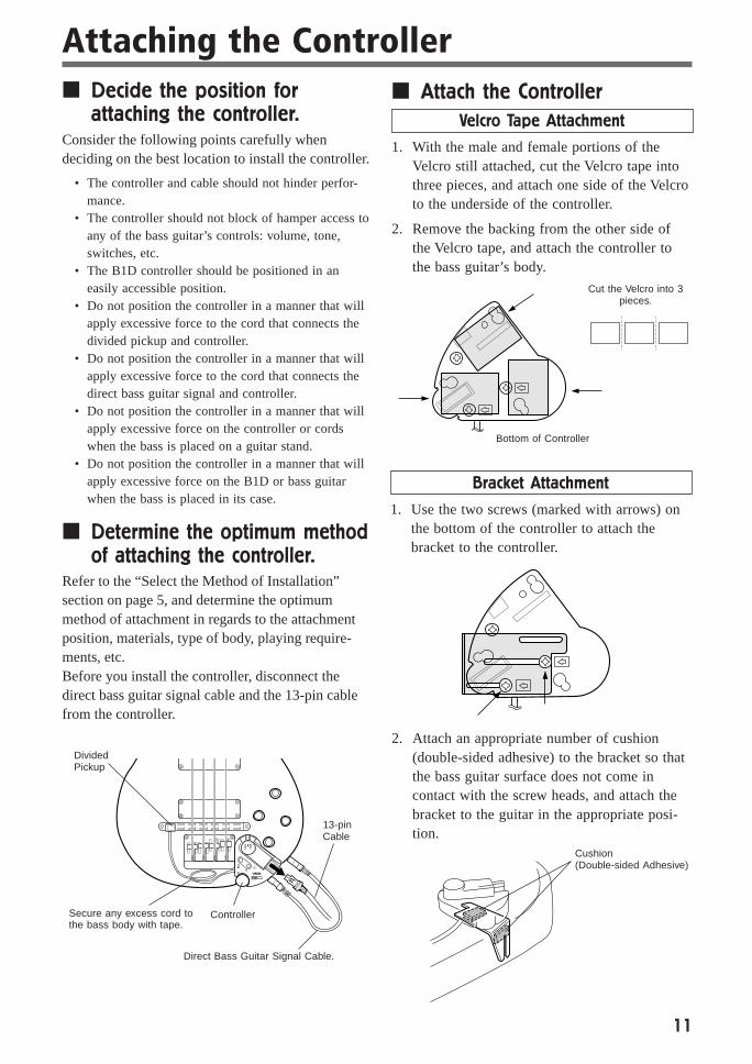
■ Attach the ControllerVelcro Tape Attachment
1. With the male and female portions of theVelcro still attached, cut the Velcro tape intothree pieces, and attach one side of the Velcroto the underside of the controller.
2. Remove the backing from the other side ofthe Velcro tape, and attach the controller tothe bass guitar’s body.
Attaching the Controller
13-pinCable
Bracket Attachment
1. Use the two screws (marked with arrows) onthe bottom of the controller to attach thebracket to the controller.
2. Attach an appropriate number of cushion(double-sided adhesive) to the bracket so thatthe bass guitar surface does not come incontact with the screw heads, and attach thebracket to the guitar in the appropriate posi-tion.
DividedPickup
ControllerSecure any excess cord tothe bass body with tape.
Direct Bass Guitar Signal Cable.
Bottom of Controller
Cut the Velcro into 3pieces.
Cushion(Double-sided Adhesive)
12
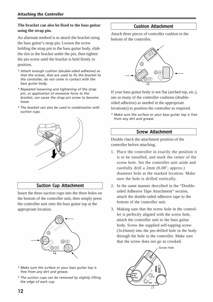
The bracket can also be fixed to the bass guitarusing the strap pin.
An alternate method is to attach the bracket usingthe bass guitar’s strap pin. Loosen the screwholding the strap pin to the bass guitar body, slidethe slot in the bracket under the pin, then tightenthe pin screw until the bracket is held firmly inposition.
* Attach enough cushion (double-sided adhesive) sothat the screws, that are used to fix the bracket tothe controller, do not come in contact with thebass guitar body.
* Repeated loosening and tightening of the strappin, or application of excessive force to thebracket, can cause the strap pin screw to becomeloose.
* The bracket can also be used in combination withsuction cups.
Cushion Attachment
Attach three pieces of controller cushion to thebottom of the controller.
Suction Cup Attachment
Insert the three suction cups into the three holes onthe bottom of the controller unit, then simply pressthe controller unit onto the bass guitar top at theappropriate location.
* Make sure the surface or your bass guitar top isfree from any dirt and grease.
* The suction cups can be removed by slightly liftingthe edge of each cup.
If your bass guitar body is not flat (arched top, etc.),use as many of the controller cushions (double-sided adhesive) as needed in the appropriatelocation(s) to position the controller as required.
* Make sure the surface or your bass guitar top is freefrom any dirt and grease.
Screw Attachment
Double check the attachment position of thecontroller before attaching.
1. Place the controller in exactly the position itis to be installed, and mark the center of thescrew hole. Set the controller unit aside andcarefully drill a 2mm (0.08", approx.)diameter hole at the marked location. Makesure the hole is drilled vertically.
2. In the same manner described in the “Double-sided Adhesive Tape Attachment” section,attach the double-sided adhesive tape to thebottom of the controller unit.
3. Making sure that the screw hole in the control-ler is perfectly aligned with the screw hole,attach the controller unit to the bass guitarbody. Screw the supplied self-tapping screw(3x16mm) into the pre-drilled hole in the bodythrough the hole in the controller. Make surethat the screw does not go in crooked.
Screw Hole
Attaching the Controller

13
Make sure the power is OFF on all relatedequipment before making any connections.Also, set the amp volume to its lowest setting.
1. Use the direct bass guitar signal cable toconnect the bass guitar’s output jack to theB1D’s bass guitar input jack.
* Always connect the direct bass guitar signal cable,even if you don’t intend to use the direct bassguitar sound. The direct signal cable is essential forproper grounding, to minimize noise, and preventelectric shock.
Connections
2. Use the 13-pin cable to connect the GuitarMIDI Converter’s Divided Input to the B1D.
Direct Bass GuitarSignal Cable
13-pin Cable
* For extra security and to prevent damage it is agood idea to pass the cable between the strap andbass guitar body near the body strap pin.
* The special 13-pin cable is of a locking type. Todisconnect the cable, always unlock the cable andthen remove the cable by gripping the plug firmly,not by pulling on the cable.
2. Unplug cable by grippingthe plug firmly.
1. Press release button.
Strap
13-pin Cable
3. Connect the tone generator, bass amp, andany other related devices to the GuitarMIDI Converter.
4. Adjust the pickup settings on the GuitarMIDI Converter (Refer to your GuitarMIDI Converter manual).If you are using the G50 Guitar MIDI Con-verter, set the GUITAR/BASS mode switchlocated on the rear panel of the G50 to theBASS position.
5. Turn ON the power in the following order,
Tone Generator →Guitar MIDI Converter → Related Equipment →Bass Amp
The B1D power indicator should light. If you
are using the G50, “ASS” will appear inthe display. With this, connection is finishedand you are ready to play.
* If the indicator does not light, double check allconnections.
G50 Rear Panel Connections
to tone generatorMU80, VL70-m, etc.
from foot switchFC4, FC5, etc.
from MIDI foot controllerMFC10, etc.
to bass amp.

14
If you are using the Yamaha Guitar MIDI Converter G50, set the following settingson the G50.
Also, if you play with your fingers, the pickingfinger may hit the adjacent low string causingunwanted triggering of the lower string (ex. whenyou play the A string, notes on the E string sound),so it is preferable to use lower input gain settings(E string) to remedy this problem.On the same fret play with the same amount offorce on all of the strings, while checking thebalance of the input level value set the input gainlevel and make sure that each string is in balancewith the others (→ Refer to the list on pg. 7).
● Set the Playing Style (Refer to theG50 owner’s manual: pg. 14)
The Playing Style setting adjusts the G50’s inputlevel and velocity to the playing style you intend touse.
Pic (Pick): Pick modeStandard setting for the bass mode, good forplaying with your fingers. If you play with a pickor use a tapping technique, this mode should alsobe used.
SLP (Slap): Slap modeUse this mode if you use a slap technique. How-ever, it is recommended that you mix the directbass sound with the synth so that the slap attackcovers up any delay in the triggering of synthsounds.
G50 Settings
● Guitar/Bass Mode SwitchWith the G50 power switched OFF. Set theGUITAR/BASS mode switch, located on the rearpanel of the G50, to the BASS position.When the G50 is in the BASS mode, “ASS”will appear on the G50 display when the power isswitched ON. Verify.
● Load the Bass Preset ProgramWith the G50 set to the BASS mode, bass presetprogram memory will be loaded into the G50’smemory when the Initialize operation (→ refer tothe G50 owner’s manual: pg. 20) or the PresetProgram Set operation (→refer to the G50 owner’smanual: pg. 8) is carried out.
* Bass Preset Program List(Refer to the G50 owner’s manual: pg. 25).
* When the G50 is initialized, all program datastored in the G50 will be erased (it will be replacedwith new data). If you have any data you want tosave, use the MIDI bulk dump operation to savethe data to an external MIDI device (→Refer to theG50 owner’s manual: pg.19).
● Set the Input Gain (Refer to the G50owner’s manual: pg. 9)
Under normal playing conditions, the input levelvalue should be between 20 and 60, playing hardermay increase the level to about 90 or more.However, the level for the E and B strings mayonly reach 80 when played hard.Even if the input level is set to the above levels,you may experience double notes, other notes maysound, or the 5th and 7th fret harmonics mayunexpectedly sound, so the input gain level foreach string should be carefully adjusted. Particu-larly, the E and B strings should be set to lowlevels (5-10).

15
After connection and setup is finished, try to play your bass guitar.
Controller and Switch
● Play a synth sound only• Set the output select switch to the SYNTH
position
• Use the VOL knob to control the synthvolume. Turn the knob right to increase thevolume and left to decrease.
• The UP/DOWN buttons can be used to selectdifferent synthesizer voices and other func-tions on the Guitar MIDI Converter.If you are using the G50, you can increase ordecrease, by a value of one, Program MemoryNumbers, Parameter Values, Program Num-bers, and Octave Shift Values.Refer to the Guitar MIDI Converter manualfor more information.
● Play the Bass Guitar sound only.• Set the output select switch to the BASS
position.
• The bass direct signal volume will not changeeven if the VOL knob is turned.
● Play the Bass Guitar and Synth soundstogether.
• Set the output select switch to the MIXposition.
• Turning the VOL knob changes the synthesizervolume only. The bass guitar’s volume will notchange.
• The UP/DOWN buttons function is identical tothat described in the “Play a synth sound only”section above.
Volume Control
Memory or Parameter,etc., switch
16
Please use the following functions to get the most out of your B1D and G50.
How can you effectively use the SplitMode functions?As an example, you can play a slap bass tone on thefirst and second strings, and a fingered bass tone onthe third and fourth strings, each style (or string) canbe assigned sounds. You can get the best characteristicsout of each style (or strings) by assigning differenttones to different strings (→ Refer to the G50 owner’smanual: pg. 17).
How can you effectively use the SplitMode in relation to picking position.As an example, you can set up your bass so that byplaying in the normal picking position you can play afingered bass tone, and playing closer to the bridgeyou can play a slap bass tone, and switch between thetwo sounds by just changing your playing position (→Refer to the G50 owner’s manual : pg. 16 [Q: Split]).Program change data is transmitted when the splitmode is active (when the tone is changed), and thisdata can be used with a sequencer as well.
How can you effectively use thePicking Position Control function?If you set the G50’s [H: Program Number] to a synthbass tone, and set the [T: Picking Position Control] to“74” (filter cut-off frequency), you can create a techno-bass tone (→ Refer to the G50 owner’s manual: pg. 17).
How can you effectively use the TouchControl function?If you set the G50’s [H: Program Number] to a synthbass tone, and set the [W: Touch Control] to “74”(filter cut-off frequency), you can create a synth-basstone (→ Refer to the G50 owner’s manual: pg. 17).
How can you effectively use theSustain 2 function?Use a non-decaying tone, pluck and hold the loweststring (multiple strings can also be held), and you canplay a melody on the other strings while the low stringpitch sustains (→ Refer to the G50 owner’s manual: pg. 18).
How can you effectively use the Holdfunction?Use a non-decaying tone, play a chord and hold it,play a melody with a different tone while the chordholds. Also, by assigning an [H: Program Number]program that is set to “oFF”, to the [Y: Sustain/HoldPedal] you can hold a chord and play the direct basssound over the chord (→ Refer to the G50 owner’smanual: pg. 18).
Is the direct bass sound, coming from theG50, inferior?The B1D has an internal buffer so there should be noproblems with noise, but variations in signal levelsmay make the sound produced by the G50 may be alittle louder or softer than the bass’s direct sound.
Getting the most out of your B1D & G50
What playing style will you use?Set the G50’s [A: Playing Style] to the “Pic” (pick)setting if you are going to play with your fingers.When using a pick, as long as you use a firm attack, notletting the pick “slide” over the strings, there should beno problems.If you are going to use a slap technique, set the [A:Playing Style] to the “SLP” (slap) setting. However, itis recommended that you mix the direct bass sound withthe synth so that the slap attack covers up any delay inthe triggering of synth sounds.Also, the synth sound is sometimes delayed due to thedifficulties in accurately processing the slap attack, it isrecommended that a “sweep” type of synth sound beused to provide a better overall sound (→ Refer to theG50 owner’s manual: pg. 14).
Can you adjust the dynamics?Set the G50’s [D: Velocity] setting according to the typeof sound you will be using. The following settings arepossible, “nAr” (narrow), “nor” (normal), “uui”(wide), “1”-” 127” (fixed). The velocity settingspecifies how the G50 will control the dynamic range ofyour playing style.When programming data for a sequencer “nAr” or“1”-” 127” (fixed) settings will keep velocity data to aaverage.Also, the “uui” (wide) setting can be used in conjunc-tion with a velocity switch to change synth sounds withvelocity (→ Refer to the G50 owner’s manual: pg. 14).
Do you want to decrease pitch bend datagoing to the sequencer?Set the G50’s [E: Chromatic] setting to “On” or “ Au”.Or set the [G: Pitch Bend Range] setting to “0” andpitch bend data will not be produced at all (→ Refer tothe G50 owner’s manual: pgs. 14-15).
Can you control the synthesizer’s attackand release?By setting one of the G50’s control numbers as follows[M(O): Assignable Control Number] to “73” (AttackTime) or to “72” (Release Time), you can control theparameter with [N(P): Assignable Control Value]. Value: 0(Short) - 64 (Factory Default) - 127 (Long) (→ Refer topg. 16 in the G50 Owner’s Manual).Depending on the type of tone generator, it may beimpossible to carry out some control changes. If that is thecase, the Attack and Release Times should be set on thetone generator itself.
Do you use a fretless bass?You can use a fretless bass as well as fretted one. If youset the G50’s [E: Chromatic] setting to “oFF”, thesensitivity and unique pitch characteristics of the fretlessbass will be accurately reproduced by the G50 (→ Referto the G50 owner’s manual: pgs. 14-15).
17
If you think there may be a problem with your B1D and G50, first check the infor-mation below for a possible solution. If that does not solve the problem, contact thenearest Yamaha dealer or the music store where you purchased the device.
Troubleshooting
Low pitches produce no sound.→ Is the GUITAR/BASS selector switch on the rear
panel of the G50 set to BASS? (→ pg. 14).
Multiple notes sound.→ If the string vibrates against a fret other, than the
one being fretted, the resulting noise may interferewith the pitch being played. Try readjusting theneck of your bass guitar or adjust the string heightto eliminate unwanted noise.
→ Are the strings coming into contact with the dividedpickup? Adjust the height of the pickup (→ pg. 7).
→ Is the G50 Input Level set too high? Try loweringthe Input Gain Level (→ pg. 7 & 14).
→ Are your fingernails hitting a string or do you rubthe pick against a string? If you play hard you mayget multiple notes even if the Play Style is set to the“ SLP” (slap) mode.
→ Is the G50 [G: Pitch Bend Range] setting set to“ 0”? Try setting it to “12” (→ G50 owner’smanual: pg. 15).
Strings sound without being played.→ Is the G50 Input Level set too high? You can
control the problem using the G50 [B: Note ONLevel] but, first try lowering the Input Gain Level(→ pg. 7 & 14. Also, the G50 owner’s manual: pg.14).
The 5th and 7th fret harmonics sound.→ If the G50’s Input Level is set too high, harmonics
will easily be picked up by the pickup. Try loweringthe Input Gain Level (→ pg. 7 & 14).
→ Harmonics are easily produced if the string isfretted exactly on top of the fret and then the fingeris removed from the string. Try fretting the stringslightly behind the fret.
The pitch is off.→ Are the strings coming into contact with the divided
pickup? Adjust the height of the pickup (→ pg. 7).
→ Is the G50’s Input Level set too high? Try loweringthe Input Gain Level (→pg. 7 & 14).
→ Properly tune the bass guitar. Also, make sure thefrets are properly tuned. If the G50 [E: Chromatic]setting is set to “On”, pitch bend can only be donein half-tone increments, even using the “Au”setting, if the bass guitar’s pitch is slightly off, thatpitch will be used as the center of the pitch bend(→ G50 owner’s manual: pg. 14).
→ If the G50 [G: Pitch Bend Range] and the pitchbend range setting on the tone generator differs,the pitch will be off. When you change programswith the G50, the program’s pitch bend range datais transmitted to the tone generator but, dependingupon the type of tone generator, pitch bend rangedata may not be received. In that case, the pitchbend range should be set on the tone generatoritself.If you send data to a MIDI sequencer, the pitchbend range and pitch bend center information mustbe set in the very beginning of the song in orderfor the sequencer to play back at the correct pitch.
→ Depending upon the type of tone (piano, etc). youare using, pitch bends may not match well. In thatcase try setting the G50 [E: Chromatic] to “On”or, [G: Pitch Bend Range] to “0” (→ G50 owner’smanual: pg. 14).
Vibrato is not detected.→ Set the G50 [E: Chromatic] setting to “oFF”. If it
is set to “On”, pitch bend will only change thepitch by half-tone increments or decrements. If it isset to “Au” it will be hard to detect the slightvariations of the vibrato pitch (→ G50 owner’smanual: pg. 14).
The pitch lowers a half-step when yourfinger is removed from the fret.→ When you play the bass directly, the same thing
happens, it’s just that the sound fades so quicklythat you don’t notice. This problem often occurswhen tones with a long release time are used. Ifthat is the case, try setting the G50 [E: Chromatic]to “On” and [G: Pitch Bend Range] to “12”. Or,try setting the [G: Pitch Bend Range] to “0”.
When you glissando, new notes aretriggered as you slide up the neck.→ If the range set in [G: Pitch Bend Range] is
exceeded, a new note on will be produced. Changethe range value (→ G50 owner’s manual: pg. 15).
→ Is the G50’s Input Level set too high? Try loweringthe Input Gain Level (→pg. 7 & 14). Or, play anote softly before you glissando.
18
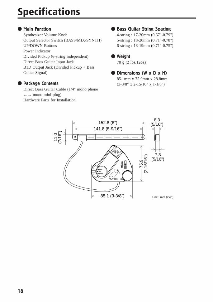
● Main FunctionSynthesizer Volume KnobOutput Selector Switch (BASS/MIX/SYNTH)UP/DOWN ButtonsPower IndicatorDivided Pickup (6-string independent)Direct Bass Guitar Input JackB1D Output Jack (Divided Pickup + BassGuitar Signal)
● Package ContentsDirect Bass Guitar Cable (1/4" mono phone←→ mono mini-plug)Hardware Parts for Installation
Specifications
● Bass Guitar String Spacing4-string : 17-20mm (0.67"-0.79")5-string : 18-20mm (0.71"-0.78")6-string : 18-19mm (0.71"-0.75")
● Weight78 g (2 lbs.12oz)
● Dimensions (W x D x H)85.1mm x 75.9mm x 28.8mm(3-3/8" x 2-15/16" x 1-1/8")
Unit : mm (inch)
152.8 (6")141.8 (5-9/16")
85.1 (3-3/8")
75.9
(2-1
5/16
")
8.3(5/16")
7.3(5/16")
11.0
(7/1
6")
19
Y A M A H A • G U I T A R • M I D I • C O N V E R T E R
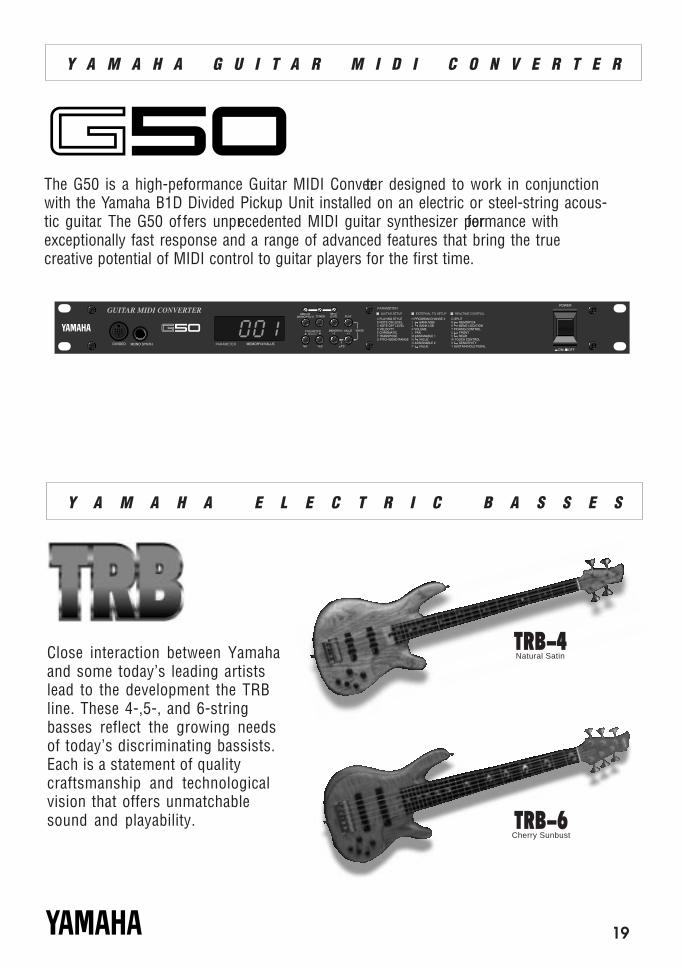
Close interaction between Yamahaand some today’s leading artistslead to the development the TRBline. These 4-,5-, and 6-stringbasses reflect the growing needsof today’s discriminating bassists.Each is a statement of qualitycraftsmanship and technologicalvision that offers unmatchablesound and playability.
Y A M A H A • E L E C T R I C • B A S S E S
The G50 is a high-performance Guitar MIDI Converter designed to work in conjunctionwith the Yamaha B1D Divided Pickup Unit installed on an electric or steel-string acous-tic guitar. The G50 offers unprecedented MIDI guitar synthesizer performance withexceptionally fast response and a range of advanced features that bring the truecreative potential of MIDI control to guitar players for the first time.
TRB-4Natural Satin
TRB-6Cherry Sunbust
For details of products, please contact your nearest Yamaha or theauthorized distributor listed below.
Pour plus de détails sur les produits, veuillez-vous adresser àYamaha ou au distributeur le plus proche de vous figurant dans laliste suivante.
Die Einzelheiten zu Produkten sind bei Ihrer unten aufgeführtenNiederlassung und bei Yamaha Vertragshändlern in den jeweiligenBestimmungsländern erhältlich.
Para detalles sobre productos, contacte su tienda Yamaha máscercana o el distribuidor autorizado que se lista debajo.
NORTH AMERICA
CANADAYamaha Canada Music Ltd.135 Milner Avenue, Scarborough, Ontario,M1S 3R1, CanadaTel: 416-298-1311
U.S.A.Yamaha Corporation of America6600 Orangethorpe Ave., Buena Park, Calif.90620, U.S.A.Tel: 714-522-9011
MIDDLE & SOUTH AMERICA
MEXICOYamaha De Mexico S.A. De C.V.,Departamento de ventasJavier Rojo Gomez No.1149, Col. Gpe DelMoral, Deleg. Iztapalapa, 09300 Mexico, D.F.Tel: 686-00-33
BRASILYamaha Musical Do Brasil LTDA.Ave. Reboucas 2636, São Paulo, BrasilTel: 011-853-1377
PANAMAYamaha De Panama S.A.Edificio Interseco, Calle Elvira Mendez no.10,Piso 3, Oficina #105, Ciudad de Panama, PanamaTel: 507-69-5311
OTHER LATIN AMERICAN COUNTRIESAND CARIBBEAN COUNTRIES
Yamaha Music Latin America Corp.6101 Blue Lagoon Drive, Miami, Florida 33126,U.S.A.Tel: 305-261-4111
EUROPE
THE UNITED KINGDOMYamaha-Kemble Music (U.K.) Ltd.Sherbourne Drive, Tilbrook, Milton Keynes,MK7 8BL, EnglandTel: 01908-366700
IRELANDDanfay Ltd.61D, Sallynoggin Road, Dun Laoghaire, Co. DublinTel: 01-2859177
GERMANY/SWITZERLANDYamaha Europa GmbH.Siemensstraße 22-34, 25462 Rellingen,F.R. of GermanyTel: 04101-3030
AUSTRIAYamaha Music AustriaSchleiergasse 20, A-1100 Wien AustriaTel: 0222-60203900
THE NETHERLANDSYamaha Music NederlandKanaalweg 18G, 3526KL, Utrecht, The NetherlandsTel: 030-2828411
BELGIUMYamaha Music BelgiumKeiberg Imperiastraat 8, 1930 Zaventem, BelgiumTel: 02-7258220
FRANCEYamaha Musique France,Division ProfessionnelleBP 70-77312 Marne-la-Valée Cedex 2, FranceTel: 01-64-61-4000
ITALYYamaha Musica Italia S.P.A.,Combo DivisionViale Italia 88, 20020 Lainate (Milano), ItalyTel: 02-935-771
SPAINYamaha-Hazen Electronica Musical, S.A.Jorge Juan 30, 28001, Madrid, SpainTel: 91-577-7270
PORTUGALValentim de Carvalho CI SAEstrada de Porto Salvo, Paço de Arcos 2780Oeiras, PortugalTel: 01-443-3398/4030/1823
GREECEPhilippe Nakas S.A.Navarinou Street 13, P.Code 10680, Athens,GreeceTel: 01-364-7111
SWEDENYamaha Scandinavia ABJ. A. Wettergrens Gata 1, Box 30053S-400 43 Göteborg, SwedenTel: 031 89 34 00
DENMARKYS Copenhagen Liaison OfficeGeneratorvej 8B, DK-2730 Herlev, DenmarkTel: 44 92 49 00
FINLANDWarner Music Finland OY/Fazer MusicAleksanterinkatu 11, P.O. Box 260SF-00101 Helsinki, FinlandTel: 0435 011
NORWAYNarud Yamaha ASGrini Næringspark 17, N-1345 Østerås, NorwayTel: 67 14 47 90
ICELANDSkifan HFSkeifan 17 P.O. Box 8120IS-128 Reykjavik, IcelandTel: 525 5000
OTHER EUROPEAN COUNTRIESYamaha Europa GmbH.Siemensstraße 22-34, 25462 Rellingen, F.R. ofGermanyTel: 04101-3030
ASIA
HONG KONGTom Lee Music Co., Ltd.11/F., Silvercord Tower 1, 30 Canton Road,Tsimshatsui, Kowloon, Hong KongTel: 730-1098
INDONESIAPT. Yamaha Music Indonesia (Distributor)PT. NusantikGedung Yamaha Music Center, Jalan Jend. GatotSubroto Kav. 4, Jakarta 12930, IndonesiaTel: 21-520-2577
KOREACosmos Corporation#131-31, Neung-Dong, Sungdong-Ku, SeoulKoreaTel: 02-466-0021~5
MALAYSIAYamaha Music Malaysia, Sdn., Bhd.16-28, Jalan SS 2/72, Petaling Jaya, Selangor,MalaysiaTel: 3-717-8977
PHILIPPINESYupangco Music Corporation339 Gil J. Puyat Avenue, P.O. Box 885 MCPO,Makati, Metro Manila, PhilippinesTel: 819-7551
SINGAPOREYamaha Music Asia Pte., Ltd.Blk 17A Toa Payoh #01-190 Lorong 7Singapore 1231Tel: 354-0133
TAIWANKung Hsue She Trading Co., Ltd.No. 322, Section 1, Fu Hsing S. Road,Taipei 106, Taiwan. R.O.C.Tel: 02-709-1266
THAILANDSiam Music Yamaha Co., Ltd.865 Phornprapha Building, Rama I Road,Patumwan, Bangkok 10330, ThailandTel: 2-215-3443
THE PEOPLE’S REPUBLIC OF CHINAAND OTHER ASIAN COUNTRIES
Yamaha Corporation,International Marketing DivisionNakazawa-cho 10-1, Hamamatsu, Japan 430Tel: 053-460-2317
OCEANIA
AUSTRALIAYamaha Music Australia Pty. Ltd.17-33 Market Street, South Melbourne, Vic.3205, AustraliaTel: 3-699-2388
NEW ZEALANDMusic Houses of N.Z. Ltd.146/148 Captain Springs Road, Te Papapa,Auckland, New ZealandTel: 9-634-0099
COUNTRIES AND TRUSTTERRITORIES IN PACIFIC OCEAN
Yamaha Corporation,International Marketing DivisionNakazawa-cho 10-1, Hamamatsu, Japan 430Tel: 053-460-2317
AFRICA
Yamaha Corporation,International Marketing DivisionNakazawa-cho 10-1, Hamamatsu, Japan 430Tel: 053-460-2312
MIDDLE EAST
TURKEY/CYPRUSYamaha Europa GmbH.Siemensstraße 22-34, 25462 Rellingen,F.R. of GermanyTel: 04101-3030
OTHER COUNTRIESYamaha Corporation,International Marketing DivisionNakazawa-cho 10-1, Hamamatsu, Japan 430Tel: 053-460-2312
SY11
HEAD OFFICE Yamaha Corporation, Electronic Musical Instrument DivisionNakazawa-cho 10-1, Hamamatsu, Japan 430Tel: 053-460-2445

M.D.G., EMI Division © Yamaha Corporation 1997
VZ13850 704POCP5.2-01A0 Printed in Japan