Embed Size (px)
Citation preview

Manualdel
Usuario
40Hp
Owner’s Manual
ENG

Read this manual carefully before operating this outboard motor. Keep this manual
onboard in a waterproof bag when boating. This manual should stay with the ouboard motor if it is sold.
.
Thank you for choosing a PowertecOut-Boards outboard motor. This Owner’s Manual contains information needed for proper operation, maintenance and care. A thorough understanding of these simple instructions will help you obtain maximum enjoyment from your new PowertecOutBoards. If you have any question about the operation or maintenance of your outboard motor, please consult a PowertecOutBoards dealer.In this Owner’s Manual particularly important information is distinguished in the followingways. The Safety Alert Symbol meansATTENTION! BECOME ALERT! YOURSAFETY IS INVOLVED!
Failure to follow WARNING instructionscould result in severe injury or death tothe machine operator, a bystander, or aperson inspecting or repairing the out-
A CAUTION indicates special precau-tions that must be taken to avoid dam-age to the outboard motor.
NOTE:A NOTE provides key information to make procedures easier or clearer.Powertec OutBoards continually seeks advancements in product design and quality. Therefore, while this manual contains the most current prod-uct information available at the time of printing, there may be minor discrepan-cies between your machine and this manal. If there is any question concern-ing this manual, please consult your PowertecOutBoards dealer. To ensure long product life, PowertecOutBoards recomends that you use the product and perform
the specified periodic inspections and maintenance by correctly following the instructions in the owner’s manual. Note that if you do not follow these instruc-tions, not only may the product break down, but the warranty will also be voided. Some countries have laws or regulations restricting users from taking the product out of the country where it was purchased, and it may be impos-sible to register the product inthe destination country. Additionally, thewarranty may not apply in certain regions.When planning to take the product to anothercountry, consult the dealer where the prod-uct was purchased for further informa-tion.If the product was purchased used, pleaseconsult your closest dealer for customer re-registration, and to be eligible for the speci-fied services.
NOTE:
The 40HP and the standard accesso-ries are used as a base for the explana-tions and illustrations in this manual. Therefore some items may not apply to every model.
General Information
CAUTION
WARNING

General Information
40HP OWNER’S MANUAL©2009 PowerTec Outboards
1st Edition, Marzo 2011All rights reserved.
Any reprinting or unauthorized usewithout the written permission of
PowerTec Outboardsis expressly prohibited.

General information .......................... 1 Identification numbers record........... 1Outboard motor serial number .......... 1Key number..................................... 1C-Tick label ............................... 1Safety information ............................ 2Important labels.............................. 3Warning labels ................................ 3Fueling instructions .......................... 4Gasoline ...................................... 4Engine oil ...................................... 4Battery requirement.......................... 4Battery specifications ..................... 4Without a rectifier or Rectifier Regulator .................................... 4 Propeller selection.......................... 5 Start-in-gear protection .................... 5Basic components ............................ 6 Main components............................. 6Fuel tank ..................................... 7Fuel joint ...................................... 7Fuel gauge .................................... 7Fuel tank cap ................................. 7Air vent screw ................................. 7Remote control................................ 7Remote control lever ......................... 7Neutral interlock trigger ................... 8Neutral throttle lever........................ 8Tiller handle .................................. 8Gear shift lever................................ 9Throttle grip .................................. 9Throttle indicator ............................. 9Throttle friction adjuster................... 10Engine stop lanyard switch ............. 10Engine stop button .......................... 11Choke knob for pull type ................. 11Manual starter handle ..................... 11Main switch .................................. 12Steering friction adjuster ................. 12Steering friction adjuster ................. 12Power trim and tilt switch on remote control or tiller handle ................... 12Trim tab with anode ........................ 12
1. º
Index
Trim rod (tilt pin) .............................. 13Tilt lock mechanism......................... 13Tilt support lever for power trim and tilt or hydro tilt model............. 13Top cowling lock lever(s) turn type)......14Tachometer ................................. 14Speedometer................................ 14Hour meter ................................ 14Warning system ............................. 14Overheat warning ............................ 15 Operation .................................... 16 Installation................................. 16Mounting the outboard motor .......... 16Clamping the outboard motor.......... 17Breaking in engine ......................... 18Gasoline and engine oil mixing chart (25:1).................................. 18Procedure for pre-mixed models .....18 Preoperation checks ...................... 19Fuel .......................................... 19Oil ............................................ 19Controls .................................19 Engine .................................... 20Filling fuel and engine oil ............... 20Filling fuel for portable tank ............. 20Gasoline and oil mixing ................... 20Operating engine ........................... 21Feeding fuel (portable tank) ............ 21Starting engine .............................. 22Warming up engine........................ 28Choke start models ......................... 28Electric start and prime start models ....................................... 28Shifting ...................................... 29Forward (tiller handle and rmote con-trol models) ................................ 30Reverse (automatic reverse lock and power trim and tilt modls)................ 30Reverse (manual tilt and hydro tilt models) ....................................... 30Stopping engine ............................. 31Procedure ....................................... 31
Trimming outboard motor............... 32Adjusting trim angle ........................ 32Adjusting trim angle for hydro tiltmodels ........................................ 32Adjusting boat trim .......................... 33Tilting up and down ........................ 34Procedure for tilting up (hydro tilt models) ......................... 35Procedure for tilting up .................... 36 Procedure for tilting down ............... 36Procedure for tilting down (manual and hydro tilt models) ..... 37Cruising in shallow water ............... 37Hydro tilt models ............................. 38Power trim and tilt models / power tilt models........................... 38Cruising in other conditions............ 39Maintenance............................... 40 Specifications .............................. 40 Transporting and stor-ing outboard motor ........ 42Clamp screw mounting models ....... 42Storing outboard motor ................... 42Procedure ................................... 43L u b r i c a t i o n (except oil injection models) ...44Battery care................................. 44Cleaning the outboard motor .......... 45Checking painted surface of motor......................................... 45Periodic maintenance..................... 45Replacement parts .......................... 45Maintenance chart .......................... 46Greasing..................................... 48Cleaning and adjusting spark plug ........49Checking fuel system ...................... 50Inspecting fuel filter ......................... 50Cleaning fuel filter ........................... 51Inspecting idling speed.................... 51Checking wiring and connectors .... 52Exhaust leakage............................. 52Water leakage ............................... 52Checking power trim and tilt
power tilt system ......... 53Checking propeller .......................... 53Removing the propeller ................... 53Installing the Propeller..................... 54Changing gear oil ............................ 54Cleaning fuel tank ........................... 55Inspecting and replacinganode(s)....... 56Checking battery (for electric start models) ................. 56Connecting the battery ................... 57Disconnecting the battery................ 58Checking top cowling ...................... 58Coating the boat bottom .................. 58Trouble Recovery............................ 59 Troubleshooting ............................. 59 Temporary action in emergency .... 62Impact damage ............................ 62Replacing fuse .............................. 63Power trim and tilt / power tilt will not operate.................................. 63Starter will not operate .................... 63Emergency starting engine ............. 64Treatment of submerged motor ..... 65Procedure................................... 65
Index
1
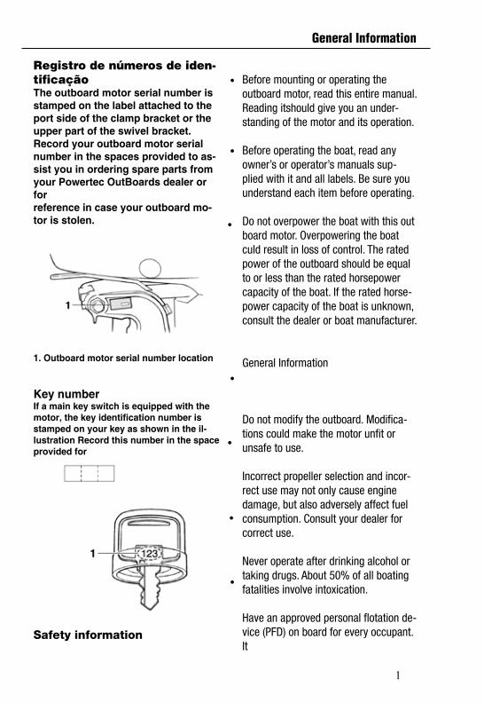
Registro de números de iden-tificaçãoThe outboard motor serial number isstamped on the label attached to the port side of the clamp bracket or the upper part of the swivel bracket.Record your outboard motor serial number in the spaces provided to as-sist you in ordering spare parts from your Powertec OutBoards dealer or forreference in case your outboard mo-tor is stolen.
1. Outboard motor serial number location
Key numberIf a main key switch is equipped with the motor, the key identification number is stamped on your key as shown in the il-lustration Record this number in the space provided for
Safety information
Before mounting or operating the outboard motor, read this entire manual. Reading itshould give you an under-standing of the motor and its operation.
Before operating the boat, read any owner’s or operator’s manuals sup-plied with it and all labels. Be sure you understand each item before operating.
Do not overpower the boat with this out board motor. Overpowering the boat culd result in loss of control. The rated power of the outboard should be equal to or less than the rated horsepower capacity of the boat. If the rated horse-power capacity of the boat is unknown, consult the dealer or boat manufacturer.
General Information
Do not modify the outboard. Modifica-tions could make the motor unfit or unsafe to use.
Incorrect propeller selection and incor-rect use may not only cause engine damage, but also adversely affect fuel consumption. Consult your dealer for correct use.
Never operate after drinking alcohol or taking drugs. About 50% of all boating fatalities involve intoxication.
Have an approved personal flotation de-vice (PFD) on board for every occupant. It
General Information
2
is a good idea to wear a PFD wheneverboating. At a minimum, children and non-swimmers should always wear PFDs, andeveryone should wear PFDs when thereare potentially hazardous boating condi-tions.
Gasoline is highly flammable, and its va-pors are flammable and explosive. Handleand store gasoline carefully. Make surethere are no gas fumes or leaking fuel be-fore starting the engine.
This product emits exhaust gases whichcontain carbon monoxide, a colorless,odorless gas which may cause brain dam-age or death when inhaled. Symptoms in-clude nausea, dizziness, and drowsiness.Keep cockpit and cabin areas well ventilat-ed. Avoid blocking exhaust outlets.
Check throttle, shift, and steering for prop-er operation before starting the engine.
Attach the engine stop switch lanyard to asecure place on your clothing, or your armor leg while operating. If you accidentallyleave the helm, the lanyard will pull fromthe switch, stopping the engine.
Know the marine laws and regulationswhere you will be boating - and obey them.
Stay informed about the weather. Checkweather forecasts before boating. Avoidboating in hazardous weather.
Tell someone where you are going: leavea Float Plan with a responsible person. Besure to cancel the Float Plan when you re-turn.
Use common sense and good judgmentwhen boating. Know your abilities, and besure you understand how your boat han-dles under the different boating conditionsyou may encounter. Operate within yourlimits, and the limits of your boat. Alwaysoperate at safe speeds, and keep a careful
watch for obstacles and other traffic.
Always watch carefully for swimmers dur-ing the engine operation.
Stay away from swimming areas.
When a swimmer is in the water near you-shift into neutral and shut off the engine.
Do not illegally discard empty containers used to replace or replenish oil. For the correct processing of empty containers, consult the dealer where you purchased the oil.
When replacing oils used to lubricate the product (engine or gear oil), be sure to wipe away any spilt oil. Never pour oil with- out using a funnel or similar device. If necessary, verify the necessary replace-ment procedure with the dealer.
Never illegally discard (dump) the product. PowertecOutBoards recommends consult-ing the dealer on discarding the product
General Information
3
CAUTION
CAUTION
General Information
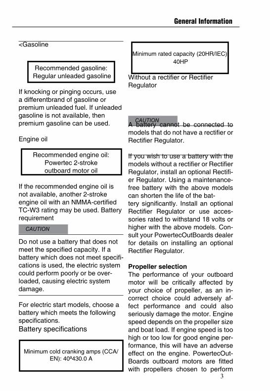
<Gasoline
Recommended gasoline: Regular unleaded gasoline
If knocking or pinging occurs, use a differentbrand of gasoline or premium unleaded fuel. If unleaded gasoline is not available, thenpremium gasoline can be used.
Engine oil
Recommended engine oil:Powertec 2-stroke outboard motor oil
If the recommended engine oil is not available, another 2-stroke engine oil with an NMMA-certified TC-W3 rating may be used. Battery requirement
Do not use a battery that does not meet the specified capacity. If a battery which does not meet specifi-cations is used, the electric system could perform poorly or be over-loaded, causing electric systemdamage.
For electric start models, choose a battery which meets the following specifications.Battery specifications
Minimum cold cranking amps (CCA/EN): 40ª430.0 A
Minimum rated capacity (20HR/IEC): 40HP
Without a rectifier or RectifierRegulator
A battery cannot be connected to models that do not have a rectifier or Rectifier Regulator.
If you wish to use a battery with the models without a rectifier or Rectifier Regulator, install an optional Rectifi-er Regulator. Using a maintenance-free battery with the above models can shorten the life of the bat-tery significantly. Install an optional Rectifier Regulator or use acces-sories rated to withstand 18 volts or higher with the above models. Con-sult your PowertecOutBoards dealer for details on installing an optional Rectifier Regulator.
Propeller selectionThe performance of your outboard motor will be critically affected by your choice of propeller, as an in-correct choice could adversely af-fect performance and could also seriously damage the motor. Engine speed depends on the propeller size and boat load. If engine speed is too high or too low for good engine per-formance, this will have an adverse effect on the engine. PowertecOut-Boards outboard motors are fitted with propellers chosen to perform
4
General Information
Never illegally discard (dump) the product. PowertecOutBoards recommends consulting the dealer on discarding the product.
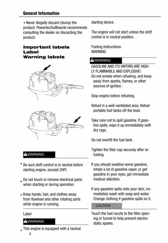
Important labelsLabelWarning labels
Be sure shift control is in neutral beforestarting engine. (except 2HP)
Do not touch or remove electrical partswhen starting or during operation.
Keep hands, hair, and clothes awayfrom flywheel and other rotating partswhile engine is running.
Label
This engine is equipped with a neutral
starting device.
The engine will not start unless the shiftcontrol is in neutral position.
Fueling instructionsWARNING
GASOLINE AND ITS VAPORS ARE HIGH-LY FLAMMABLE AND EXPLOSIVE!Do not smoke when refueling, and keep away from sparks, flames, or other sources of ignition.
Stop engine before refueling.
Refuel in a well-ventilated area. Refuel portable fuel tanks off the boat.
Take care not to spill gasoline. If gaso- line spills, wipe it up immediately with dry rags.
Do not overfill the fuel tank.
Tighten the filler cap securely after re- fueling.
If you should swallow some gasoline, inhale a lot of gasoline vapor, or get gasoline in your eyes, get immediate medical attention.
If any gasoline spills onto your skin, im- mediately wash with soap and water. Change clothing if gasoline spills on it.
Touch the fuel nozzle to the filler open- ing or funnel to help prevent electro- static sparks.
CAUTION
WARNING
WARNING
WARNING
5
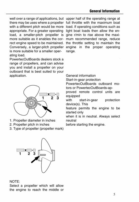
upper half of the operating range at full throttle with the maximum boat load. If operating conditions such aslight boat loads then allow the en-gine r/min to rise above the maxi-mum recommended range, reduce the throttle setting to maintain the engine in the proper operating range.For instructions on propeller remov-al and in-stallation, see page 57.5 General informationStart-in-gear protectionPowertecOutBoards outboard mo-tors or PowertecOutBoards-ap-proved remote control units are equippedwith start-in-gear protection device(s). Thisfeature permits the engine to be started onlywhen it is in neutral. Always select neutralbefore starting the engine.
well over a range of applications, but there may be uses where a propeller with a different pitch would be more appropriate. For a greater operatingload, a smaller-pitch propeller is more suitable as it enables the cor-rect engine speed to be maintained. Conversely, a larger-pitch propeller is more suitable for a smaller oper-ating load. PowertecOutBoards dealers stock a range of propellers, and can advise you and install a propeller on your outboard that is best suited to your application.
1. Propeller diameter in inches2. Propeller pitch in inches3. Type of propeller (propeller mark)
NOTE: Select a propeller which will allow the engine to reach the middle or
General Information
6
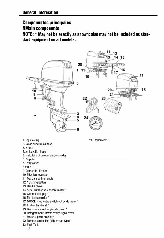
1. Top cowling2. Dated superior da hood3. Á node4. Anticavation Plate5. Nadadeira of compensaçao (anode)6. Propeller7. Entry water8.trim *9. Support for fixation10. Fricction regulator 11. Manual starting handle12. * Starting button13. Handle choke14. serial number of outboard motor *15. Command poppy *16. Throttle controller *17. MOTORr stop / stop switch out do do motor *18. fixation handle aft *19. BloqueIo levered to give elevaçao *20. Refrigerator D’Chivato refrigeraçao Water21. Motor support bracket *22. Remote control box (side mount type) *23. Fuel Tank
24. Tachometer *25. Speedometer *26. Hour Meter *
Componentes principaiesNMain componentsNOTE: * May not be exactly as shown; also may not be included as stan-dard equipment on all models.
General Information
7
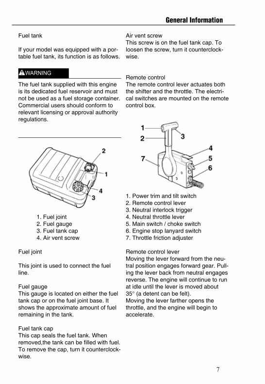
Fuel tank
If your model was equipped with a por-table fuel tank, its function is as follows.
The fuel tank supplied with this engine is its dedicated fuel reservoir and must not be used as a fuel storage container. Commercial users should conform to relevant licensing or approval authority regulations.
1. Fuel joint2. Fuel gauge3. Fuel tank cap4. Air vent screw
Fuel joint
This joint is used to connect the fuel line.
Fuel gaugeThis gauge is located on either the fuel tank cap or on the fuel joint base. It shows the approximate amount of fuel remaining in the tank.
Fuel tank capThis cap seals the fuel tank. When removed,the tank can be filled with fuel. To remove the cap, turn it counterclock-wise.
Air vent screwThis screw is on the fuel tank cap. To loosen the screw, turn it counterclock-wise.
Remote controlThe remote control lever actuates both the shifter and the throttle. The electri-cal switches are mounted on the remote control box.
1. Power trim and tilt switch2. Remote control lever3. Neutral interlock trigger4. Neutral throttle lever5. Main switch / choke switch6. Engine stop lanyard switch7. Throttle friction adjuster
Remote control leverMoving the lever forward from the neu-tral position engages forward gear. Pull-ing the lever back from neutral engages reverse. The engine will continue to run at idle until the lever is moved about 35° (a detent can be felt).Moving the lever farther opens the throttle, and the engine will begin to accelerate.
WARNING
General Information
8
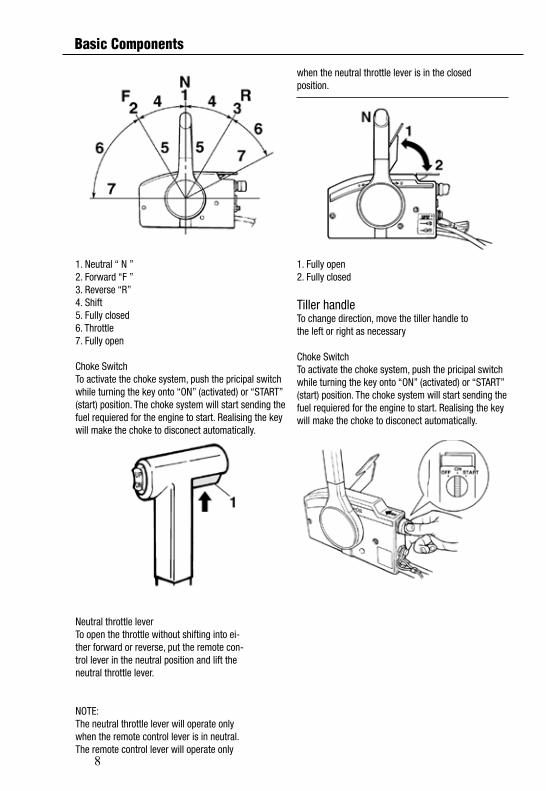
1. Neutral “ N ”2. Forward “F ”3. Reverse “R”4. Shift5. Fully closed6. Throttle7. Fully open
Choke SwitchTo activate the choke system, push the pricipal switch while turning the key onto “ON” (activated) or “START” (start) position. The choke system will start sending the fuel requiered for the engine to start. Realising the key will make the choke to disconect automatically.
Neutral throttle leverTo open the throttle without shifting into ei-ther forward or reverse, put the remote con-trol lever in the neutral position and lift theneutral throttle lever.
NOTE:The neutral throttle lever will operate onlywhen the remote control lever is in neutral.The remote control lever will operate only
when the neutral throttle lever is in the closedposition.
1. Fully open2. Fully closed
Tiller handleTo change direction, move the tiller handle tothe left or right as necessary
Choke SwitchTo activate the choke system, push the pricipal switch while turning the key onto “ON” (activated) or “START” (start) position. The choke system will start sending the fuel requiered for the engine to start. Realising the key will make the choke to disconect automatically.
Basic Components
9
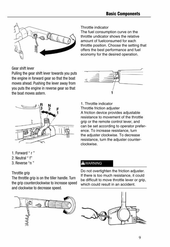
Gear shift leverPulling the gear shift lever towards you putsthe engine in forward gear so that the boatmoves ahead. Pushing the lever away fromyou puts the engine in reverse gear so thatthe boat moves astern.
1. Forward “ r ”2. Neutral “ f”3. Reverse “n ”
Throttle gripThe throttle grip is on the tiller handle. Turnthe grip counterclockwise to increase speedand clockwise to decrease speed.
Throttle indicatorThe fuel consumption curve on the throttle undicator shows the relative amount of fuelconsumed for each throttle position. Choose the setting that offers the best performance and fuel economy for the desired operation.
1. Throttle indicatorThrottle friction adjusterA friction device provides adjustable resistance to movement of the throttle grip or the remote control lever, and can be set according to operator prefer-ence. To increase resistance, turn the adjuster clockwise. To decrease resistance, turn the adjuster counter-clockwise.
Do not overtighten the friction adjuster. If there is too much resistance, it could be difficult to move throttle lever or grip,which could result in an accident.
WARNING
Basic Components
10
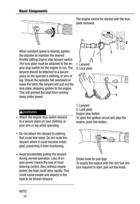
When constant speed is desired, tighten the adjuster to maintain the desired throttle setting.Engine stop lanyard switchThe lock plate must be attached to the en-gine stop switch for the engine to run. Thelanyard should be attached to a secure place on the operator’s clothing, or arm or leg. Should the operator fall overboard or leave the helm, the lanyard will pull out the lock plate, stopping ignition to the engine. This will prevent the boat from running away under power.
WARNINGAttach the engine stop switch lanyardto a secure place on your clothing, oryour arm or leg while operating.
Do not attach the lanyard to clothingthat could tear loose. Do not route thelanyard where it could become entan-gled, preventing it from functioning.
Avoid accidentally pulling the lanyardduring normal operation. Loss of en-gine power means the loss of moststeering control. Also, without enginepower, the boat could slow rapidly. Thiscould cause people and objects in theboat to be thrown forward.
NOTE:
The engine cannot be started with the lockplate removed.
1. Lanyard2. Lock plate
1. Lanyard2. Lock plateEngine stop buttonTo open the ignition circuit and stop the engine, push this button.
Choke knob for pull typeTo supply the engine with the rich fuel mixture required to start, pull out this knob.
WARNING
Basic Components
11
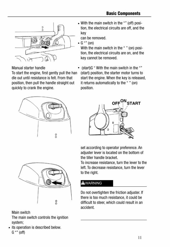
Manual starter handleTo start the engine, first gently pull the handle out until resistance is felt. From that position, then pull the handle straight out quickly to crank the engine.
Main switchThe main switch controls the ignition system;its operation is described below.G “” (off)
With the main switch in the “” (off) posi-tion, the electrical circuits are off, and the keycan be removed.G “” (on)With the main switch in the “ ” (on) posi-tion, the electrical circuits are on, and the key cannot be removed. (start)G “ With the main switch in the “” (start) position, the starter motor turns to start the engine. When the key is released, it returns automatically to the “ ” (on) position.
set according to operator preference. An adjuster lever is located on the bottom of the tiller handle bracket.To increase resistance, turn the lever to theleft. To decrease resistance, turn the lever to the right.
Do not overtighten the friction adjuster. Ifthere is too much resistance, it could bedifficult to steer, which could result in anaccident.
WARNING
Basic Components
12
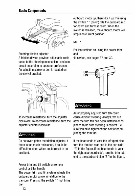
Steering friction adjusterA friction device provides adjustable resis-tance to the steering mechanism, and can be set according to operator preference. An adjusting screw or bolt is located on the swivel bracket.
To increase resistance, turn the adjusterclockwise. To decrease resistance, turn the adjuster counterclockwise.
Do not overtighten the friction adjuster. Ifthere is too much resistance, it could bedifficult to steer, which could result in anaccident.
Power trim and tilt switch on remotecontrol or tiller handleThe power trim and tilt system adjusts theoutboard motor angle in relation to the transom. Pressing the switch “ ” (up) trims the
outboard motor up, then tilts it up. Pressingthe switch “ ” (down) tilts the outboard motor down and trims it down. When the switch is released, the outboard motor will stop in ts current position.
NOTE:
For instructions on using the power trim andtilt switch, see pages 37 and 39.
An improperly adjusted trim tab couldcause difficult steering. Always test runafter the trim tab has been installed or re-placed to be sure steering is correct. Besure you have tightened the bolt after ad-justing the trim tab.
If the boat tends to veer the left (port side), turn the trim tab rear end to the port side “A” in the figure. If the boat tends to veer the right (starboard side), turn the trim tab end to the starboard side “B” in the figure.
WARNING
WARNING
Basic Components
13
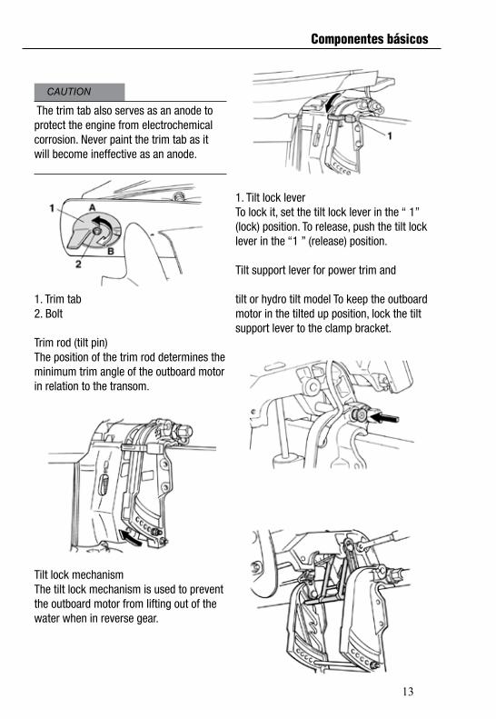
The trim tab also serves as an anode toprotect the engine from electrochemicalcorrosion. Never paint the trim tab as itwill become ineffective as an anode.
1. Trim tab2. Bolt
Trim rod (tilt pin)The position of the trim rod determines theminimum trim angle of the outboard motor in relation to the transom.
Tilt lock mechanismThe tilt lock mechanism is used to preventthe outboard motor from lifting out of the water when in reverse gear.
1. Tilt lock leverTo lock it, set the tilt lock lever in the “ 1”(lock) position. To release, push the tilt locklever in the “1 ” (release) position.
Tilt support lever for power trim and
tilt or hydro tilt model To keep the outboard motor in the tilted up position, lock the tilt support lever to the clamp bracket.
CAUTION
Componentes básicos
14
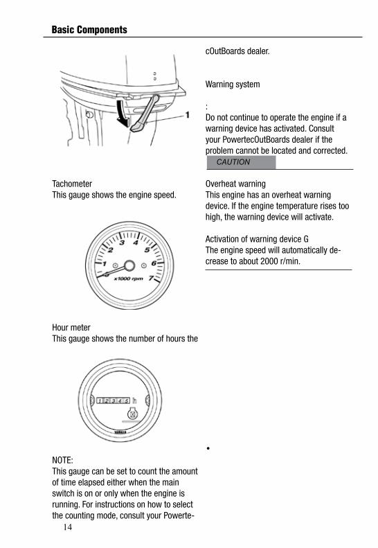
TachometerThis gauge shows the engine speed.
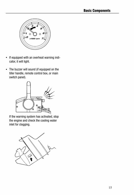
Hour meterThis gauge shows the number of hours the
NOTE:This gauge can be set to count the amount of time elapsed either when the main switch is on or only when the engine is running. For instructions on how to select the counting mode, consult your Powerte-
CAUTION
Basic Components
cOutBoards dealer.
Warning system
:Do not continue to operate the engine if awarning device has activated. Consultyour PowertecOutBoards dealer if the problem cannot be located and corrected.
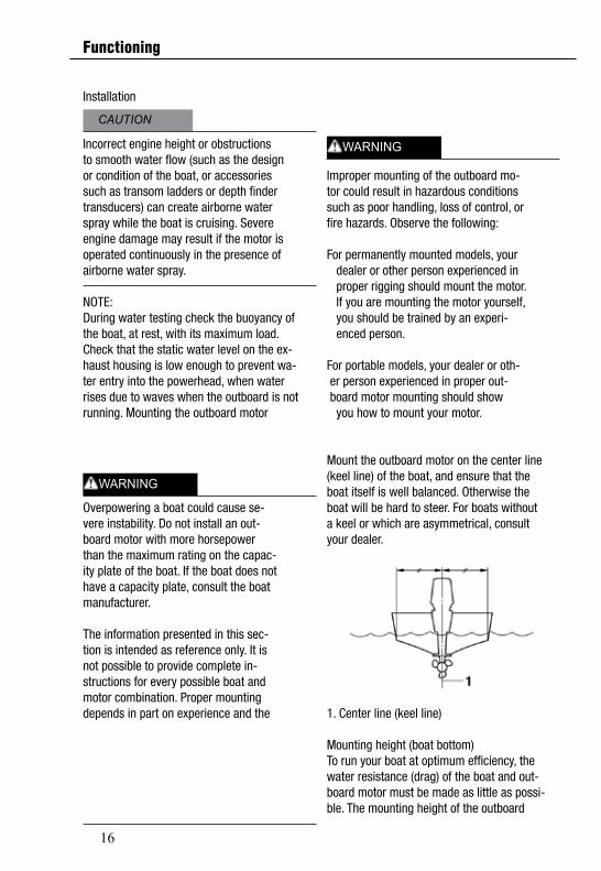
Overheat warningThis engine has an overheat warning device. If the engine temperature rises too high, the warning device will activate.
Activation of warning device G The engine speed will automatically de-crease to about 2000 r/min.
15
If equipped with an overheat warning indi-cator, it will light.
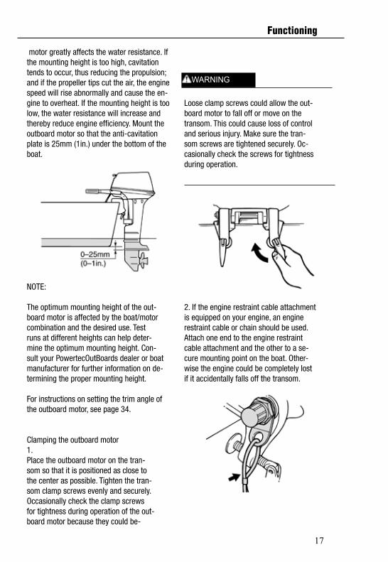
The buzzer will sound (if equipped on thetiller handle, remote control box, or mainswitch panel).
If the warning system has activated, stop the engine and check the cooling water inlet for clogging.
Basic Components
16
Installation
Incorrect engine height or obstructionsto smooth water flow (such as the designor condition of the boat, or accessoriessuch as transom ladders or depth findertransducers) can create airborne waterspray while the boat is cruising. Severeengine damage may result if the motor isoperated continuously in the presence ofairborne water spray.
NOTE:During water testing check the buoyancy ofthe boat, at rest, with its maximum load.Check that the static water level on the ex-haust housing is low enough to prevent wa-ter entry into the powerhead, when waterrises due to waves when the outboard is notrunning. Mounting the outboard motor
Overpowering a boat could cause se-vere instability. Do not install an out-board motor with more horsepowerthan the maximum rating on the capac-ity plate of the boat. If the boat does nothave a capacity plate, consult the boatmanufacturer.
The information presented in this sec-tion is intended as reference only. It isnot possible to provide complete in-structions for every possible boat andmotor combination. Proper mountingdepends in part on experience and the
Improper mounting of the outboard mo-tor could result in hazardous conditionssuch as poor handling, loss of control, orfire hazards. Observe the following:
For permanently mounted models, your dealer or other person experienced in proper rigging should mount the motor. If you are mounting the motor yourself, you should be trained by an experi- enced person.
For portable models, your dealer or oth- er person experienced in proper out- board motor mounting should show you how to mount your motor.
Mount the outboard motor on the center line(keel line) of the boat, and ensure that theboat itself is well balanced. Otherwise theboat will be hard to steer. For boats withouta keel or which are asymmetrical, consultyour dealer.
1. Center line (keel line) Mounting height (boat bottom)To run your boat at optimum efficiency, thewater resistance (drag) of the boat and out-board motor must be made as little as possi-ble. The mounting height of the outboard
Functioning
WARNING
WARNING
CAUTION
17
motor greatly affects the water resistance. Ifthe mounting height is too high, cavitationtends to occur, thus reducing the propulsion;and if the propeller tips cut the air, the enginespeed will rise abnormally and cause the en-gine to overheat. If the mounting height is toolow, the water resistance will increase andthereby reduce engine efficiency. Mount theoutboard motor so that the anti-cavitationplate is 25mm (1in.) under the bottom of theboat.
NOTE:
The optimum mounting height of the out-board motor is affected by the boat/motorcombination and the desired use. Testruns at different heights can help deter-mine the optimum mounting height. Con-sult your PowertecOutBoards dealer or boatmanufacturer for further information on de-termining the proper mounting height.
For instructions on setting the trim angle ofthe outboard motor, see page 34.
Clamping the outboard motor1.Place the outboard motor on the tran-som so that it is positioned as close tothe center as possible. Tighten the tran-som clamp screws evenly and securely.Occasionally check the clamp screwsfor tightness during operation of the out-board motor because they could be-
Loose clamp screws could allow the out-board motor to fall off or move on thetransom. This could cause loss of controland serious injury. Make sure the tran-som screws are tightened securely. Oc-casionally check the screws for tightnessduring operation.
2. If the engine restraint cable attachmentis equipped on your engine, an enginerestraint cable or chain should be used.Attach one end to the engine restraintcable attachment and the other to a se-cure mounting point on the boat. Other-wise the engine could be completely lostif it accidentally falls off the transom.
WARNING
Functioning
18
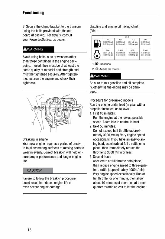
3. Secure the clamp bracket to the transomusing the bolts provided with the out-board (if packed). For details, consultyour PowertecOutBoards dealer.
Avoid using bolts, nuts or washers otherthan those contained in the engine pack-aging. If used, they must be of at least thesame quality of material and strength andmust be tightened securely. After tighten-ing, test run the engine and check theirtightness.
Breaking in engineYour new engine requires a period of break-in to allow mating surfaces of moving parts towear in evenly. Correct break-in will help en-sure proper performance and longer enginelife.
Failure to follow the break-in procedurecould result in reduced engine life oreven severe engine damage.
Gasoline and engine oil mixing chart(25:1)
Be sure to mix gasoline and oil complete-ly, otherwise the engine may be dam-aged.
Procedure for pre-mixed modelsRun the engine under load (in gear with apropeller installed) as follows.1. First 10 minutes: Run the engine at the lowest possible speed. A fast idle in neutral is best.2. Next 50 minutes: Do not exceed half throttle (approxi- mately 3000 r/min). Vary engine speed occasionally. If you have an easy-plan- ing boat, accelerate at full throttle onto plane, then immediately reduce the throttle to 3000 r/min or less.3. Second hour: Accelerate at full throttle onto plane, then reduce engine speed to three-quar- ter throttle (approximately 4000 r/min). Vary engine speed occasionally. Run at full throttle for one minute, then allow about 10 minutes of operation at three- quarter throttle or less to let the engine
CAUTION
WARNING
WARNING
Functioning
19
cool.
4.Third through tenth hours:Avoid operating at full throttle for morethan 5 minutes at a time. Let the enginecool between full-throttle runs. Vary en-gine speed occasionally.
5.After the first 10 hours:Operate the engine normally. Use thestandard premix ratio of gasoline and oil.For details on mixing fuel and oil, seepage 26.
If any item in the preoperation check isnot working properly, have it inspectedand repaired before operating the out-board motor. Otherwise an accidentcould occur.
Do not start the engine out of water. Over-heating and serious engine damage canoccur.
FuelCheck to be sure you have plenty of fuelfor your trip.
Make sure there are no fuel leaks or gaso-line fumes.
Check fuel line connections to be sure theyare tight (if equipped PowertecOutBoards fuel tank orboat tank).
Be sure the fuel tank is positioned on a se-cure, flat surface, and that the fuel line isnot twisted or flattened, or likely to contactsharp objects (if equipped PowertecOutBoards fueltank or boat tank).
OilCheck to be sure you have plenty of oil foryour trip.Controls5.Check throttle, shift, and steering for prop-er operation before starting the engine.
The controls should work smoothly, with-out binding or unusual free play.
Look for loose or damaged connections.
Check operation of the starter and stopswitches when the outboard motor is in thewater.
EngineCheck the engine and engine mounting.
Look for loose or damaged fasteners.
Check the propeller for damage.Filling fuel and engine oil
Filling fuel for portable tankWARNINGGasoline and its vapors are highly flam-mable and explosive. Keep away fromsparks, cigarettes, flames, or othersources of ignition.
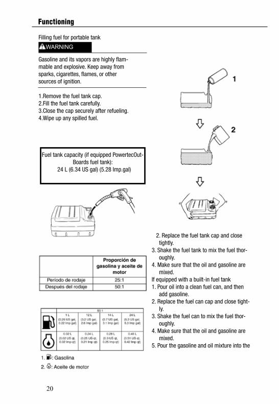
1.Remove the fuel tank cap.2.Fill the fuel tank carefully.3.Close the cap securely after refueling.Wipe up any spilled fuel.
Fuel tank capacity (if equipped PowertecOut-Boardsfuel tank):
24 L (6.34 US gal) (5.28 Imp.gal)
CAUTION
WARNING
Functioning
20
Filling fuel for portable tank
Gasoline and its vapors are highly flam-mable and explosive. Keep away fromsparks, cigarettes, flames, or othersources of ignition.
1.Remove the fuel tank cap.2.Fill the fuel tank carefully.3.Close the cap securely after refueling.4.Wipe up any spilled fuel.
Fuel tank capacity (if equipped PowertecOut-Boards fuel tank):
24 L (6.34 US gal) (5.28 Imp.gal)
2. Replace the fuel tank cap and close tightly.3. Shake the fuel tank to mix the fuel thor- oughly.4. Make sure that the oil and gasoline are mixed.If equipped with a built-in fuel tank1. Pour oil into a clean fuel can, and then add gasoline.2. Replace the fuel can cap and close tight- ly.3. Shake the fuel can to mix the fuel thor- oughly.4. Make sure that the oil and gasoline are mixed.5. Pour the gasoline and oil mixture into the
WARNING
Functioning
21
Avoid using any oil other than the spec-ified type.
Use a thoroughly blended fuel-oil mix-ture.
If the mixture is not thoroughly mixed,or if the mixing ratio is incorrect, thefollowing problems could occur. Low
oil ratio: Lack of oil could cause majorengine trouble, such as piston seizure.
High oil ratio: Too much oil could causefouled spark plugs, smoky exhaust,and heavy carbon deposits.
NOTE:If using a permanently installed tank, pourthe oil gradually as the gasoline is being add-ed to the tank.
Before starting the engine, make surethat the boat is tightly moored and thatyou can steer clear of any obstructions.Be sure there are no swimmers in thewater near you.
When the air vent screw is loosened,gasoline vapor will be released. Gaso-line is highly flammable, and its vaporsare flammable and explosive. Refrainfrom smoking, and keep away fromopen flames and sparks while loosen-ing the air vent screw.This product emits exhaust gaseswhich contain carbon monoxide, a col-brain damage or death when inhaled.Symptoms include nausea, dizziness,and drowsiness. Keep cockpit and cab-in areas well ventilated. Avoid blockingexhaust outlets.
1.If there is an air vent screw on the fueltank cap, loosen it 2 or 3 turns
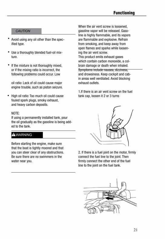
2. If there is a fuel joint on the motor, firmlyconnect the fuel line to the joint. Thenfirmly connect the other end of the fuelline to the joint on the fuel tank.
CAUTION
WARNING
Functioning

22
3. If a steering friction adjuster is providedon your outboard motor, securely attachthe fuel line to the fuel line clamp.
NOTE:During engine operation place the tank hori-zontally, otherwise fuel cannot be drawnfrom the fuel tank.
4. Squeeze the primer pump with the outletend up until you feel it become firm.
Starting engine
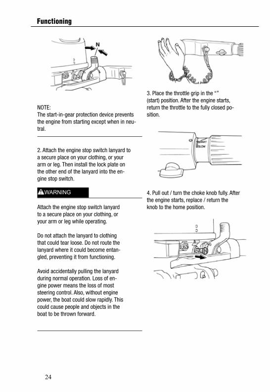
Manual start models (tiller control)1. Place the gear shift lever in neutral.
NOTE:The start-in-gear protection device preventsthe engine from starting except when in neu-tral.
2. Attach the engine stop switch lanyard toa secure place on your clothing, or yourarm or leg. Then install the lock plate onthe other end of the lanyard into the en-gine stop switch.
Attach the engine stop switch lanyardto a secure place on your clothing, oryour arm or leg while operating.
Do not attach the lanyard to clothingthat could tear loose. Do not route thelanyard where it could become entan-gled, preventing it from functioning.
Avoid accidentally pulling the lanyardduring normal operation. Loss of en-gine power means the loss of moststeering control. Also, without enginepower, the boat could slow rapidly. Thiscould cause people and objects in theboat to be thrown forward.
WARNING
Functioning
23
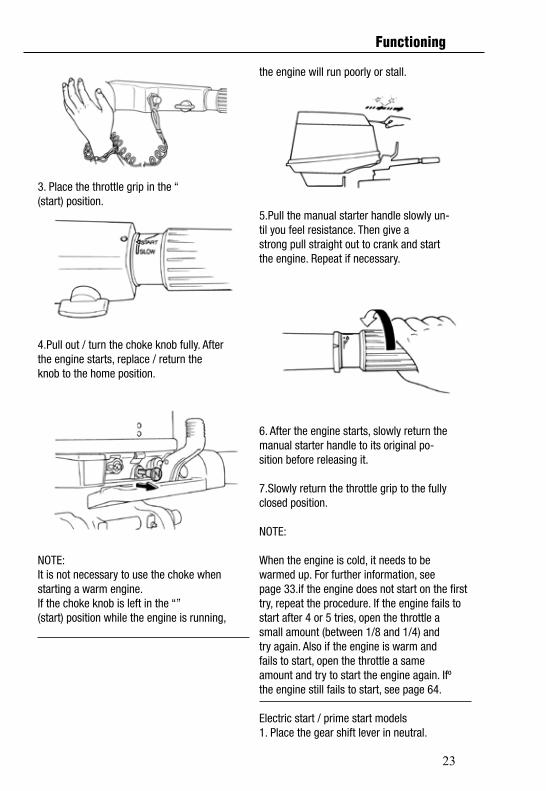
3. Place the throttle grip in the “(start) position.
4.Pull out / turn the choke knob fully. Afterthe engine starts, replace / return theknob to the home position.
NOTE:It is not necessary to use the choke whenstarting a warm engine.If the choke knob is left in the “”(start) position while the engine is running,
the engine will run poorly or stall.
5.Pull the manual starter handle slowly un-til you feel resistance. Then give astrong pull straight out to crank and startthe engine. Repeat if necessary.
6. After the engine starts, slowly return themanual starter handle to its original po-sition before releasing it.
7.Slowly return the throttle grip to the fullyclosed position.
NOTE:
When the engine is cold, it needs to bewarmed up. For further information, seepage 33.if the engine does not start on the first try, repeat the procedure. If the engine fails tostart after 4 or 5 tries, open the throttle asmall amount (between 1/8 and 1/4) andtry again. Also if the engine is warm andfails to start, open the throttle a sameamount and try to start the engine again. Ifºthe engine still fails to start, see page 64.
Electric start / prime start models1. Place the gear shift lever in neutral.
Functioning
24
NOTE:The start-in-gear protection device preventsthe engine from starting except when in neu-tral.
2. Attach the engine stop switch lanyard toa secure place on your clothing, or yourarm or leg. Then install the lock plate onthe other end of the lanyard into the en-gine stop switch.
Attach the engine stop switch lanyardto a secure place on your clothing, oryour arm or leg while operating.
Do not attach the lanyard to clothingthat could tear loose. Do not route thelanyard where it could become entan-gled, preventing it from functioning.
Avoid accidentally pulling the lanyardduring normal operation. Loss of en-gine power means the loss of moststeering control. Also, without enginepower, the boat could slow rapidly. Thiscould cause people and objects in theboat to be thrown forward.
3. Place the throttle grip in the “”(start) position. After the engine starts,return the throttle to the fully closed po-sition.
4. Pull out / turn the choke knob fully. Afterthe engine starts, replace / return theknob to the home position.
WARNING
Functioning
25
6. Immediately after the engine starts, re-lease the main switch and allow it to re-
Never turn the main switch to “”(start) while the engine is running.
Do not keep the starter motor turningfor more than 5 seconds. If the startermotor is turned continuously for morethan 5 seconds, the battery will bequickly discharged, thus making it im-possible to start the engine. The startercan also be damaged. If the engine willnot start after 5 seconds of cranking,return the main switch to “ ” (on), wait10 seconds, then crank the engineagain.
NOTE
When the engine is cold, it needs to bewarmed up. For further information, see
page 33.
If the engine is warm and fails to start,open the throttle slightly and try to start theengine again. If the engine still fails tostart, see page 64.
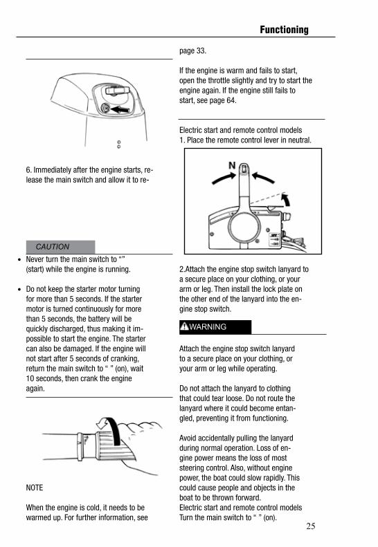
Electric start and remote control models1. Place the remote control lever in neutral.
2.Attach the engine stop switch lanyard toa secure place on your clothing, or yourarm or leg. Then install the lock plate onthe other end of the lanyard into the en-gine stop switch.
Attach the engine stop switch lanyardto a secure place on your clothing, oryour arm or leg while operating.
Do not attach the lanyard to clothingthat could tear loose. Do not route thelanyard where it could become entan-gled, preventing it from functioning.
Avoid accidentally pulling the lanyardduring normal operation. Loss of en-gine power means the loss of moststeering control. Also, without enginepower, the boat could slow rapidly. Thiscould cause people and objects in theboat to be thrown forward.Electric start and remote control modelsTurn the main switch to “ ” (on).
CAUTION
WARNING
Functioning

26
Turn the main switch to “” (start),and hold it for a maximum of 5 seconds.
4.Turn the main switch to “ ” (on).Turn the main switch to “” (start),and hold it for a maximum of 5 seconds.
Immediately after the engine starts, re-lease the main switch and allow it to re-turn to “ ” (on).
Never turn the main switch to “”(start) while the engine is running.
Do not keep the starter motor turningfor more than 5 seconds. If the startermotor is turned continuously for morethan 5 seconds, the battery will bequickly discharged, thus making it im-possible to start the engine. The startercan also be damaged. If the engine willnot start after 5 seconds of cranking,return the main switch to “ ” (on), wait10 seconds, then crank the engineagain.
NOTEWhen the engine is cold, it needs to bewarmed up. For further information, seepage 33.
If the engine is warm and fails to start,open the throttle slightly and try to start theengine again. If the engine still fails tostart, see page 64.
Functioning
27
2.Check for a steady flow of water from thecooling water pilot hole.Immediately after the engine starts, re-lease the main switch and allow it to re-turn to “ ” (on).
A continuous flow of water from the cool-ing water pilot hole shows that the waterpump is pumping water through the cool-ing passages. If water is not flowing outof the hole at all times while the engine isrunning, overheating and serious dam-age could occur. Stop the engine andcheck whether the cooling water inlet onthe lower case or the cooling water pilothole is blocked. Consult your PowertecOutBoarddealer if the problem cannot be locatedand corrected.
Before shifting, make sure there are noswimmers or obstacles in the water nearyou.
To change the boat direction or shiftingposition from forward to reverse or vice-versa, first close the throttle so that theengine idles (or runs at low speeds).
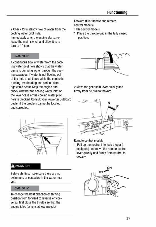
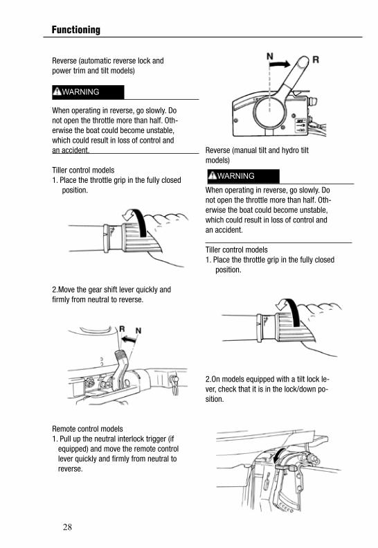
Forward (tiller handle and remotecontrol models)Tiller control models1. Place the throttle grip in the fully closed position.
2.Move the gear shift lever quickly andfirmly from neutral to forward.
Remote control models1. Pull up the neutral interlock trigger (if equipped) and move the remote control lever quickly and firmly from neutral to forward.
CAUTION
CAUTION
WARNING
Functioning
28
Reverse (automatic reverse lock andpower trim and tilt models)
When operating in reverse, go slowly. Donot open the throttle more than half. Oth-erwise the boat could become unstable,which could result in loss of control andan accident.
Tiller control models1. Place the throttle grip in the fully closed position.
2.Move the gear shift lever quickly andfirmly from neutral to reverse.
Remote control models1. Pull up the neutral interlock trigger (if equipped) and move the remote control lever quickly and firmly from neutral to reverse.
Reverse (manual tilt and hydro tiltmodels)
When operating in reverse, go slowly. Donot open the throttle more than half. Oth-erwise the boat could become unstable,which could result in loss of control andan accident.
Tiller control models1. Place the throttle grip in the fully closed position.
2.On models equipped with a tilt lock le-ver, check that it is in the lock/down po-sition.
WARNING
WARNING
Functioning
29
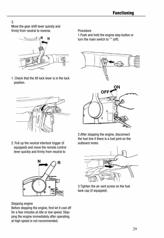
3.Move the gear shift lever quickly andfirmly from neutral to reverse.
1. Check that the tilt lock lever is in the lock position.
2. Pull up the neutral interlock trigger (if equipped) and move the remote control lever quickly and firmly from neutral to
Stopping engineBefore stopping the engine, first let it cool offfor a few minutes at idle or low speed. Stop-ping the engine immediately after operatingat high speed is not recommended.
Procedure1.Push and hold the engine stop button orturn the main switch to “” (off).
2.After stopping the engine, disconnectthe fuel line if there is a fuel joint on theoutboard motor.
3.Tighten the air vent screw on the fueltank cap (if equipped).
Functioning
30
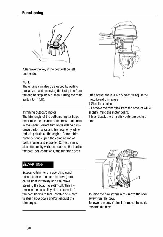
4.Remove the key if the boat will be leftunattended.
NOTE:The engine can also be stopped by pullingthe lanyard and removing the lock plate fromthe engine stop switch, then turning the mainswitch to “” (off).
Trimming outboard motorThe trim angle of the outboard motor helpsdetermine the position of the bow of the boatin the water. Correct trim angle will help im-prove performance and fuel economy whilereducing strain on the engine. Correct trimangle depends upon the combination ofboat, engine, and propeller. Correct trim isalso affected by variables such as the load in the boat, sea conditions, and running speed.
Excessive trim for the operating condi-tions (either trim up or trim down) cancause boat instability and can makesteering the boat more difficult. This in-creases the possibility of an accident. Ifthe boat begins to feel unstable or is hardto steer, slow down and/or readjust thetrim angle.
Inthe braket there is 4 o 5 holes to adjust the motorboard trim angle 1 Stop the engine2 Remove the trim stick from the bracket while slightly lifting the motor board.3 Insert back the trim stick onto the desired hole.
To raise the bow (“trim-out”), move the stick away from the bow.To lower the bow (“trim-in”), move the stick-towards the bow.
WARNING
Functioning
31
Make test runs with the trim set to differentangles to find the position that works best foryour boat and operating conditions.
Stop the engine before adjusting thetrim angle.Be sure all people are clear of the out-board motor when adjusting the tilt an-gle, also be careful not to pinch anybody parts between the drive unit andclamp bracket.
Use caution when trying a trim positionfor the first time. Increase speed gradu-ally and watch for any signs of instabil-ity or control problems. Improper trimangle can cause loss of control.
Be sure all people are clear of the out-board motor when adjusting the tilt an-gle, also be careful not to pinch anybody parts between the drive unit andclamp bracket.
Use caution when trying a trim positionfor the first time. Increase speed gradu-ally and watch for any signs of instabil-ity or control problems. Improper trimangle can cause loss of control.Use the power tilt switch located on thebottom engine cowling (if equipped)only when the boat is at a completestop with the engine off.
Make test runs with the trim set to differentangles to find the position that works best for
your boat and operating conditions.
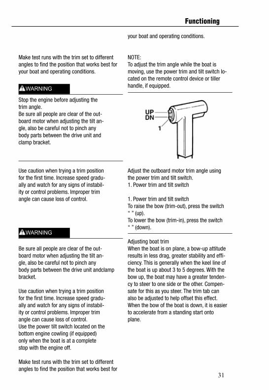
NOTE:To adjust the trim angle while the boat ismoving, use the power trim and tilt switch lo-cated on the remote control device or tillerhandle, if equipped.
Adjust the outboard motor trim angle usingthe power trim and tilt switch.1. Power trim and tilt switch
1. Power trim and tilt switchTo raise the bow (trim-out), press the switch“ ” (up).To lower the bow (trim-in), press the switch“ ” (down).
Adjusting boat trimWhen the boat is on plane, a bow-up attituderesults in less drag, greater stability and effi-ciency. This is generally when the keel line ofthe boat is up about 3 to 5 degrees. With thebow up, the boat may have a greater tenden-cy to steer to one side or the other. Compen-sate for this as you steer. The trim tab canalso be adjusted to help offset this effect.When the bow of the boat is down, it is easierto accelerate from a standing start ontoplane.
WARNING
WARNING
Functioning
32
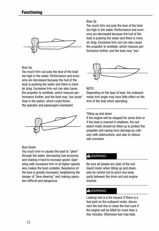
Bow UpToo much trim-out puts the bow of the boattoo high in the water. Performance and econ-omy are decreased because the hull of theboat is pushing the water and there is moreair drag. Excessive trim-out can also causethe propeller to ventilate, which reduces per-formance further, and the boat may “por poise” (hop in the water), which could throwthe operator and passengers overboard.
Bow DownToo much trim-in causes the boat to “plow”through the water, decreasing fuel economyand making it hard to increase speed. Oper-ating with excessive trim-in at higher speedsalso makes the boat unstable. Resistance atthe bow is greatly increased, heightening thedanger of “bow steering” and making opera-tion difficult and dangerous.
Bow UpToo much trim-out puts the bow of the boattoo high in the water. Performance and econ-omy are decreased because the hull of theboat is pushing the water and there is moreair drag. Excessive trim-out can also causethe propeller to ventilate, which reduces per-formance further, and the boat may “por-
NOTE:Depending on the type of boat, the outboardmotor trim angle may have little effect on thetrim of the boat when operating.
Tilting up and downIf the engine will be stopped for some time orif the boat is moored in shallows, the out-board motor should be tilted up to protect thepropeller and casing from damage by colli-sion with obstructions, and also to reducesalt corrosion.
Be sure all people are clear of the out-board motor when tilting up and down,also be careful not to pinch any bodyparts between the drive unit and enginebracket.
Leaking fuel is a fire hazard. If there is afuel joint on the outboard motor, discon-nect the fuel line or close the fuel cock ifthe engine will be tilted for more than afew minutes. Otherwise fuel may leak.
WARNING
WARNING
Functioning
33
Disconnect the fuel line from the out-board motor.
Before tilting the outboard motor, stopthe engine by following the procedureon page 34. Never tilt the outboard mo-tor while the engine is running. Severedamage from overheating can result.Do not tilt up the engine by pushing thetiller handle (if equipped) because thiscould break the handle.
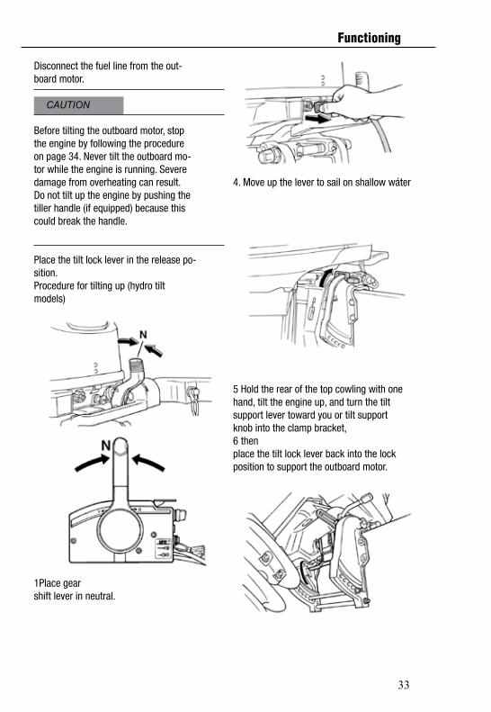
Place the tilt lock lever in the release po-sition.Procedure for tilting up (hydro tiltmodels)
1Place gearshift lever in neutral.
4. Move up the lever to sail on shallow wáter
5 Hold the rear of the top cowling with onehand, tilt the engine up, and turn the tiltsupport lever toward you or tilt supportknob into the clamp bracket, 6 thenplace the tilt lock lever back into the lockposition to support the outboard motor.
CAUTION
Functioning

34
Procedure for tilting upPower trim and tilt models / power tilt models1. Place the remote control lever / the gear shift lever in neutral.
2.Disconnect the fuel line from the out-board motor or close the fuel cock.
3.Press the power trim and tilt switch /power tilt switch “ ” (up) until the out-board motor has tilted up completely.
4. Push the tilt support knob into the clampbracket or pull the tilt support lever to-ward you to support the engine.
After tilting the outboard motor, be sureto support it with the tilt support knob ortilt support lever. Otherwise the outboardmotor could fall back down suddenly if oilin the power trim and tilt unit loses pres-sure.
5.Models equipped with trim rods: Oncethe outboard motor is supported with thetilt support lever, press the power trimand tilt switch “ ” (down) to retract thetrim rods.
Be sure to retract the trim rods complete-ly during mooring. This protects the rodsfrom marine growth and corrosion whichcould damage the power trim and tiltmechanism.
Procedure for tilting downPower trim and tilt models / power tilt models1. Push the power tilt / power trim and tiltswitch “ ” (up) until the outboard motoris supported by the tilt rod and the tiltsupport lever / tilt support knob becomesfree.Release the tilt support lever or pull outthe tilt support knob.
CAUTION
WARNING
Functioning
35
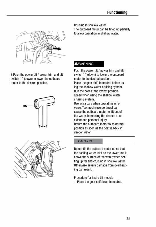
3.Push the power tilt / power trim and tiltswitch “ ” (down) to lower the outboardmotor to the desired position.
Cruising in shallow waterThe outboard motor can be tilted up partiallyto allow operation in shallow water.
Push the power tilt / power trim and tiltswitch “ ” (down) to lower the outboardmotor to the desired position.Place the gear shift in neutral before us-ing the shallow water cruising system.Run the boat at the lowest possiblespeed when using the shallow watercruising system.Use extra care when operating in re-verse. Too much reverse thrust cancause the outboard motor to lift out ofthe water, increasing the chance of ac-cident and personal injury.Return the outboard motor to its normalposition as soon as the boat is back indeeper water.
Do not tilt the outboard motor up so thatthe cooling water inlet on the lower unit isabove the surface of the water when set-ting up for and cruising in shallow water.Otherwise severe damage from overheat-ing can result.
Procedure for hydro tilt models1. Place the gear shift lever in neutral.
CAUTION
WARNING
Functioning
36
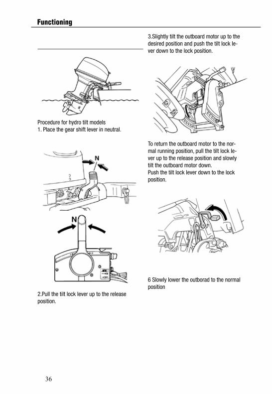
Procedure for hydro tilt models1. Place the gear shift lever in neutral.
2.Pull the tilt lock lever up to the releaseposition.
3.Slightly tilt the outboard motor up to thedesired position and push the tilt lock le-ver down to the lock position.
To return the outboard motor to the nor-mal running position, pull the tilt lock le-ver up to the release position and slowlytilt the outboard motor down.Push the tilt lock lever down to the lockposition.
6 Slowly lower the outborad to the normal position
Functioning
37
Place the gear shift in neutral beforesetting up for shallow water cruising.Return the outboard motor to its normalposition as soon as the boat is back indeeper water.
Do not tilt the outboard motor up so thatthe cooling water inlet on the lower unit isabove the surface of the water when set-ting up for and cruising in shallow water.Otherwise severe damage from overheat-ing can result.
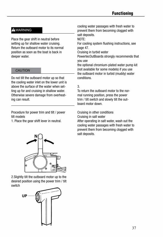
Procedure for power trim and tilt / powertilt models1. Place the gear shift lever in neutral.
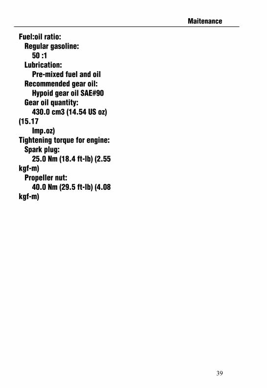
2.Slightly tilt the outboard motor up to thedesired position using the power trim / tiltswitch.
cooling water passages with fresh water toprevent them from becoming clogged withsalt deposits.NOTE:For cooling system flushing instructions, seepage 47.Cruising in turbid waterPowertecOutBoards strongly recommends that you usethe optional chromium-plated water pump kit(not available for some models) if you usethe outboard motor in turbid (muddy) waterconditions.
3.To return the outboard motor to the nor-mal running position, press the powertrim / tilt switch and slowly tilt the out-board motor down.
Cruising in other conditionsCruising in salt waterAfter operating in salt water, wash out thecooling water passages with fresh water toprevent them from becoming clogged withsalt deposits.
CAUTION
WARNING
Functioning

38
SpecificationsDimension: Overall length: mm (50.4 in) Overall width: mm (13.7 in) Overall height L: mm (53.1 in) Transom height L: 533 mm (21.0 in) Transom height X: (53.7in)Transom height S: mm(16.7 in)Transom height L: mm(21.7 in)Weight (AL)S: 6kg (164 lb) Weight (AL) L: 84.0 kg (185 lb) Performance: Full throttle operating range: 4500–5500 r/min Maximum output: 29.4 kW@5000 r/min (40 HP@5000 r/min) Idling speed (in neutral): 1000 x 50 rpmEngine: Type: 2-stroke L Displacement: 703.0 cm3 (42.90 cu.in) Bore stroke: 80.0 x 70.0 mm (3.15 2.76 in) Ignition system:Velocidade de ralentí (en ponto morto):1000 x 50 rpm
CDI Spark plug with resistor (NGK): B7HS
Spark plug gap: 0.6–0.7 mm (0.024–0.028 in) Control system: Remot control Tiller Starting system: Manual and Electric Starting carburetion system: Choke valve Min. cold cranking amps (CCA/EN): 430.0 A Min. rated capacity (20HR/IEC): 70.0 Ah Alternator output: 40hp 80 W Alternator output for battery CC: 40hp 6.0 ADrive unit: Gear positions: Forward-neutral-reverse Gear ratio: 2.00 (26/13) Trim and tilt system: Hydro tilt Power trim and tilt Propeller mark: GFuel and oil: Recommended fuel:Regular unleaded gasoline Fuel tank capacity: 24 L (6.34 US gal) (5.28 Imp.gal) Recommended engine oil: POWERTEC 2-stroke out-board motor oil
Maitenance
39
Fuel:oil ratio: Regular gasoline: 50 :1 Lubrication: Pre-mixed fuel and oil Recommended gear oil: Hypoid gear oil SAE#90 Gear oil quantity: 430.0 cm3 (14.54 US oz) (15.17 Imp.oz)Tightening torque for engine: Spark plug: 25.0 Nm (18.4 ft-lb) (2.55 kgf-m) Propeller nut: 40.0 Nm (29.5 ft-lb) (4.08 kgf-m)
Maitenance
40
Transporting and storing outboard motor
Leaking fuel is a fire hazard. Whentransporting and storing the outboardmotor, close the air vent screw and fuelcock to prevent fuel from leaking.
USE CARE when transporting fuel tank,whether in a boat or car.
DO NOT fill fuel container to maximumcapacity. Gasoline will expand consid-erably as it warms up and can build uppressure in the fuel container. This cancause fuel leakage and a potential firehazard.
Never get under the lower unit while it istilted, even if a motor support bar is used.Severe injury could occur if the outboardmotor accidentally falls.
Do not use the tilt support lever or knobwhen trailering the boat. The outboardmotor could shake loose from the tilt sup-port and fall. If the motor cannot be trail-ered in the normal running position, usean additional support device to secure itin the tilt position.
The outboard motor should be trailered andstored in the normal running position. If thereis insufficient road clearance in this position,then trailer the outboard motor in the tilt po-sition using a motor support device such asa transom saver bar. Consult your PowertecOut-Boardsdealer for further details.
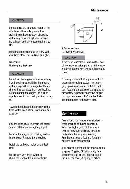
Clamp screw mounting modelsWhen transporting or storing the outboardmotor while removed from a boat, keep theoutboard motor in the attitude shown.
Storing outboard motorWhen storing your PowertecOutBoards out-board motor for prolonged periods of time (2 months orlonger), several important procedures mustbe performed to prevent excessive damage.It is advisable to have your outboard motorserviced by an authorized PowertecOutBoards dealerprior to storage. However, you, the owner,with a minimum of tools, can perform the fol-lowing procedures.
CAUTION
WARNING
WARNING
Maitenance
41
Do not place the outboard motor on itsside before the cooling water hasdrained from it completely, otherwisewater may enter the cylinder throughthe exhaust port and cause engine trou-ble.
Store the outboard motor in a dry, well-ventilated place, not in direct sunlight.
ProcedureFlushing in a test tank
Do not run the engine without supplyingit with cooling water. Either the enginewater pump will be damaged or the en-gine will be damaged from overheating.Before starting the engine, be sure tosupply water to the cooling water passag-es.
1.Wash the outboard motor body usingfresh water. For further information, seepage 50.
Disconnect the fuel line from the motoror shut off the fuel cock, if equipped.
Remove the engine top cowling and si-lencer cover. Remove the propeller.
Install the outboard motor on the testtank.
Fill the tank with fresh water toabove the level of the anti-cavitation
1. Water surface2. Lowest water level
If the fresh water level is below the levelof the anti-cavitation plate, or if the watersupply is insufficient, engine seizure mayoccur.
5.Cooling system flushing is essential toprevent the cooling system from clog-ging up with salt, sand, or dirt. In addi-tion, fogging/lubricating of the engine ismandatory to prevent excessive enginedamage due to rust. Perform the flush-ing and fogging at the same time.
Do not touch or remove electrical partswhen starting or during operation.Keep hands, hair, and clothes awayfrom the flywheel and other rotatingparts while the engine is running.Run the engine at a fast idle for a fewminutes in neutral position.
Just prior to turning off the engine, quick-ly spray “Fogging Oil” alternately intoeach carburetor or the fogging hole ofthe silencer cover, if equipped. When
CAUTION
CAUTION
CAUTION
WARNING
Maitenance
42
tails, see page 52.
Battery electrolytic fluid is dangerous; it con-tains sulfuric acid and therefore ispoisonous and highly caustic.Always follow these preventive mea-sures:
Avoid bodily contact with electrolytic fluid as it can cause severe burns or permanent eye injury.
Wear protective eye gear when han- dling or working near batteries.Antidote (EXTERNAL):
SKIN - Flush with water.
EYES - Flush with water for 15 minutes and get immediate medical attention.Antidote (INTERNAL):
Drink large quantities of water or milk followed by milk of magnesia, beaten egg, or vegetable oil. Get immediate medical attention.
Batteries also generate explosive hydro-gen gas; therefore, you should alwaysfollow these preventive measures:
Charge batteries in a well-ventilated ar- ea.
Keep batteries away from fire, sparks, or open flames (for example: welding equipment, lighted cigarettes, and so on.)G DO NOT SMOKE when charging or han- dling batteries.
KEEP BATTERIES AND ELECTROLYTICFLUID OUT OF REACH OF CHILDREN.
properly done, the engine will smoke ex-cessively and almost stall.
Remove the outboard motor from thetest tank.
Install the silencer cover/cap of fogginghole and top cowling.
If the “Fogging Oil” is not available, runthe engine at a fast idle until the fuel sys-tem becomes empty and the enginestops.
Drain the cooling water completely outof the motor. Clean the body thoroughly.
If the “Fogging Oil” is not available, re-move the spark plug(s). Pour a tea-spoonful of clean engine oil into eachcylinder. Crank several times manually.
Replace the spark plug(s).
Drain the fuel from the fuel tank.
NOTE:Store the fuel tank in a dry, well-ventilatedplace, not in direct sunlight.
Lubrication (except oil injectionmodels)
1.Grease the spark plug threads and in-stall the spark plug(s) and torque toproper specification. For information onspark plug installation, see page 53.
2.Change the gear oil. For instructions,see page 59. Inspect the oil for the pres-ence of water that indicates a leaky seal.Seal replacement should be performedby an authorized PowertecOutBoards dealer prior to use.Grease all grease fittings. For further de-
WARNING
Maitenance
43
Batteries vary among manufacturers. There-fore the following procedures may not al-ways apply.Consult your batterymanufacturer’s instructions.
Procedure
1. Disconnect and remove the battery from the boat. Always disconnect the black negative cable first to prevent the risk of shorting.
2. Clean the battery casing and terminals.
3. Fill each cell to the upper level with dis-tilled water.
4.Store the battery on a level surface in acool, dry, well-ventilated place out of di-rect sunlight.
5.Once a month, check the specific gravityof the electrolyte and recharge as re-quired to prolong battery life.
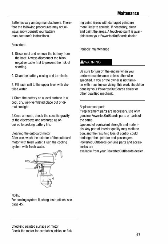
Cleaning the outboard motorAfter use, wash the exterior of the outboardmotor with fresh water. Flush the coolingsystem with fresh water.
NOTE:For cooling system flushing instructions, seepage 45.
Checking painted surface of motorCheck the motor for scratches, nicks, or flak-
ing paint. Areas with damaged paint aremore likely to corrode. If necessary, cleanand paint the areas. A touch-up paint is avail-able from your PowertecOutBoards dealer.
Periodic maintenance
Be sure to turn off the engine when youperform maintenance unless otherwisespecified. If you or the owner is not famil-iar with machine servicing, this work should be done by your PowertecOutBoards dealer orother qualified mechanic.
Replacement partsIf replacement parts are necessary, use onlygenuine PowertecOutBoards parts or parts of the sametype and of equivalent strength and materi-als. Any part of inferior quality may malfunc-tion, and the resulting loss of control couldendanger the operator and passengers.PowertecOutBoards genuine parts and acces-sories areavailable from your PowertecOutBoards dealer.
WARNING
Maitenance
44
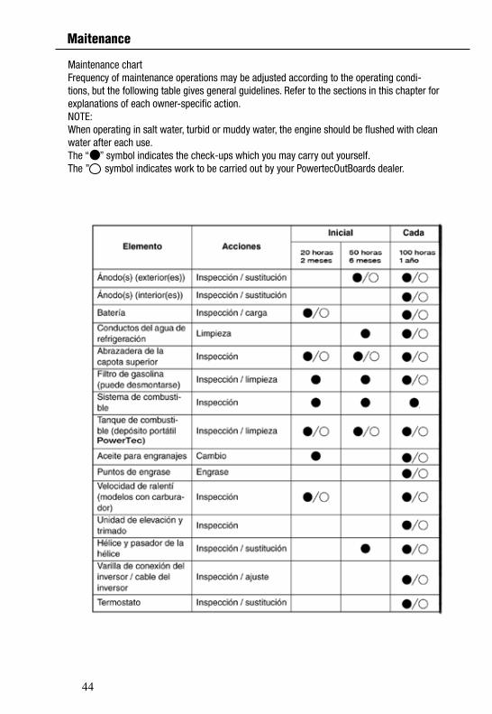
Maintenance chartFrequency of maintenance operations may be adjusted according to the operating condi-tions, but the following table gives general guidelines. Refer to the sections in this chapter forexplanations of each owner-specific action.NOTE:When operating in salt water, turbid or muddy water, the engine should be flushed with cleanwater after each use.The “ ” symbol indicates the check-ups which you may carry out yourself.The ” symbol indicates work to be carried out by your PowertecOutBoards dealer.
Maitenance

45
Maitenance
46
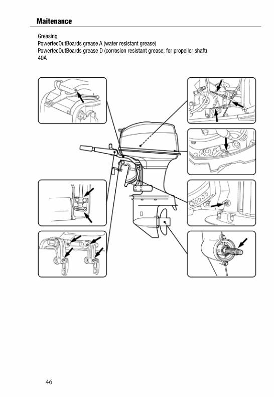
GreasingPowertecOutBoards grease A (water resistant grease)PowertecOutBoards grease D (corrosion resistant grease; for propeller shaft)40A
Maitenance
47
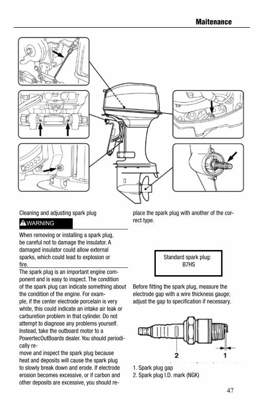
place the spark plug with another of the cor-rect type.
Standard spark plug: B7HS
Before fitting the spark plug, measure theelectrode gap with a wire thickness gauge;adjust the gap to specification if necessary.
O electrolito da batería é perigoso; comtem ácido sulfúrico e, em consequencia, é venenoso 1. Spark plug gap2. Spark plug I.D. mark (NGK)
Cleaning and adjusting spark plug
When removing or installing a spark plug,be careful not to damage the insulator. Adamaged insulator could allow externalsparks, which could lead to explosion orfire.The spark plug is an important engine com-ponent and is easy to inspect. The conditionof the spark plug can indicate something about the condition of the engine. For exam-ple, if the center electrode porcelain is verywhite, this could indicate an intake air leak orcarburetion problem in that cylinder. Do notattempt to diagnose any problems yourself.Instead, take the outboard motor to aPowertecOutBoards dealer. You should periodi-cally re-move and inspect the spark plug becauseheat and deposits will cause the spark plugto slowly break down and erode. If electrodeerosion becomes excessive, or if carbon andother deposits are excessive, you should re-
WARNING
Maitenance
48
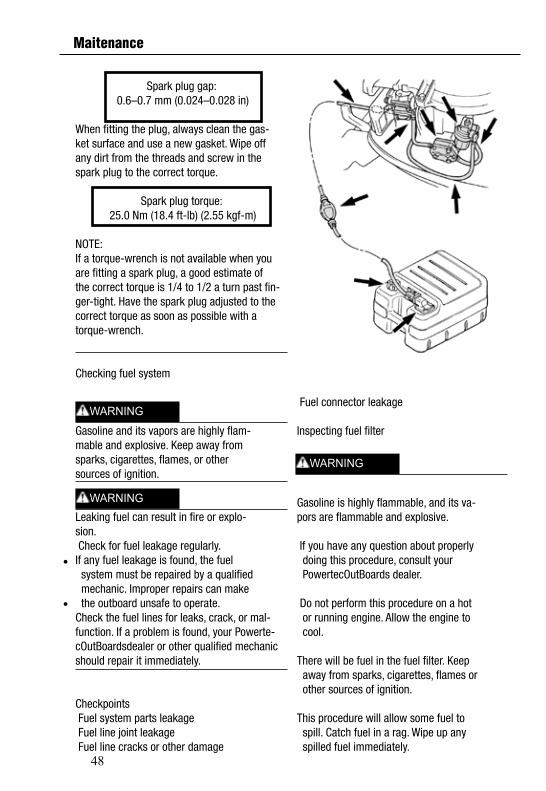
Fuel connector leakage
Inspecting fuel filter
Gasoline is highly flammable, and its va-pors are flammable and explosive.
If you have any question about properly doing this procedure, consult your PowertecOutBoards dealer.
Do not perform this procedure on a hot or running engine. Allow the engine to cool. There will be fuel in the fuel filter. Keep away from sparks, cigarettes, flames or other sources of ignition. This procedure will allow some fuel to spill. Catch fuel in a rag. Wipe up any spilled fuel immediately.
Spark plug gap: 0.6–0.7 mm (0.024–0.028 in)
When fitting the plug, always clean the gas-ket surface and use a new gasket. Wipe offany dirt from the threads and screw in thespark plug to the correct torque.
Spark plug torque: 25.0 Nm (18.4 ft-lb) (2.55 kgf-m)
NOTE:If a torque-wrench is not available when youare fitting a spark plug, a good estimate ofthe correct torque is 1/4 to 1/2 a turn past fin-ger-tight. Have the spark plug adjusted to thecorrect torque as soon as possible with atorque-wrench.
Checking fuel system
Gasoline and its vapors are highly flam-mable and explosive. Keep away fromsparks, cigarettes, flames, or othersources of ignition.
Leaking fuel can result in fire or explo-sion. Check for fuel leakage regularly.If any fuel leakage is found, the fuel system must be repaired by a qualified mechanic. Improper repairs can make the outboard unsafe to operate.Check the fuel lines for leaks, crack, or mal-function. If a problem is found, your Powerte-cOutBoardsdealer or other qualified mechanic should repair it immediately.
Checkpoints Fuel system parts leakage Fuel line joint leakage Fuel line cracks or other damage
WARNING
WARNING
WARNING
Maitenance
49
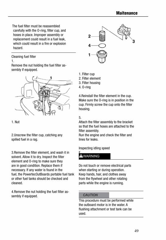
1. Filter cup2. Filter element3. Filter housing4. O-ring
4.Reinstall the filter element in the cup.Make sure the O-ring is in position in thecup. Firmly screw the cup onto the filterhousing.
5.Attach the filter assembly to the bracketso that the fuel hoses are attached to thefilter assembly.Run the engine and check the filter andlines for leaks.
Inspecting idling speedE
Do not touch or remove electrical partswhen starting or during operation.Keep hands, hair, and clothes awayfrom the flywheel and other rotatingparts while the engine is running.
This procedure must be performed whilethe outboard motor is in the water. Aflushing attachment or test tank can beused.
The fuel filter must be reassembled carefully with the O-ring, filter cup, and hoses in place. Improper assembly or replacement could result in a fuel leak, which could result in a fire or explosion hazard.
Cleaning fuel filter1.Remove the nut holding the fuel filter as-sembly if equipped.
1. Nut
2.Unscrew the filter cup, catching anyspilled fuel in a rag.
3.Remove the filter element, and wash it insolvent. Allow it to dry. Inspect the filterelement and O-ring to make sure theyare in good condition. Replace them ifnecessary. If any water is found in thefuel, the PowertecOutBoards portable fuel tank or other fuel tanks should be checked andcleaned.
4.Remove the nut holding the fuel filter as-sembly if equipped. CAUTION
WARNING
Maitenance
50
Water leakageStart the engine and check that no waterleaks from the joints between the exhaustcover, cylinder head, and body cylinder.
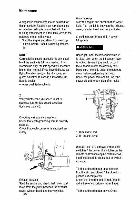
Checking power trim and tilt / powertilt system
Never get under the lower unit while itis tilted, even when the tilt support leveris locked. Severe injury could occur ifthe outboard motor accidentally falls.Make sure no one is under the outboardmotor before performing this test.Check the power trim and tilt unit / thepower tilt unit for any sign of oil leaks.
1. Trim and tilt rod2. Tilt support lever
Operate each of the power trim and tiltswitches / the power tilt switches on theremote control and engine bottom cowl-ing (if equipped) to check that all switch-es work.
Tilt the outboard motor up and checkthat the trim and tilt rod / the tilt rod ispushed out completely.Check that the trim and tilt rod / the tiltrod is free of corrosion or other flaws.
Tilt the outboard motor down. Check
A diagnostic tachometer should be used forthis procedure. Results may vary dependingon whether testing is conducted with theflushing attachment, in a test tank, or with theoutboard motor in the water.1. Start the engine and allow it to warm up fully in neutral until it is running smooth- ly.
NOTE:Correct idling speed inspection is only possi-ble if the engine is fully warmed up. If notwarmed up fully, the idle speed will measurehigher than normal. If you have difficulty ver-ifying the idle speed, or the idle speed re-quires adjustment, consult a PowertecOut-Boards dealeror other qualified mechanic.
2.Verify whether the idle speed is set tospecification. For idle speed specifica-tions, see page 46.
Checking wiring and connectorsCheck that each grounding wire is properlysecured.Check that each connector is engaged se-curely.
Exhaust leakageStart the engine and check that no exhaustleaks from the joints between the exhaustcover, cylinder head, and body cylinder.
WARNING
Maitenance
51
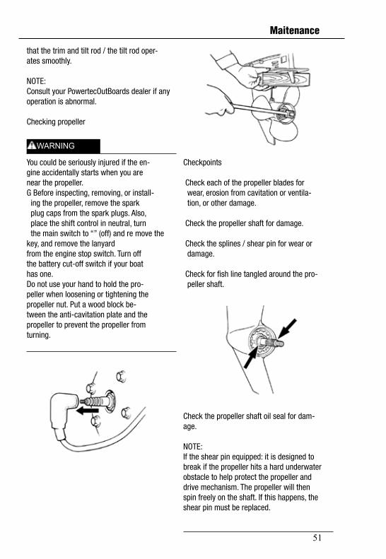
Checkpoints
Check each of the propeller blades for wear, erosion from cavitation or ventila- tion, or other damage.
Check the propeller shaft for damage.
Check the splines / shear pin for wear or damage.
Check for fish line tangled around the pro- peller shaft.
Check the propeller shaft oil seal for dam-age.
NOTE:If the shear pin equipped: it is designed tobreak if the propeller hits a hard underwaterobstacle to help protect the propeller anddrive mechanism. The propeller will thenspin freely on the shaft. If this happens, theshear pin must be replaced.
that the trim and tilt rod / the tilt rod oper-ates smoothly.
NOTE:Consult your PowertecOutBoards dealer if any operation is abnormal.
Checking propeller
You could be seriously injured if the en-gine accidentally starts when you arenear the propeller.G Before inspecting, removing, or install- ing the propeller, remove the spark plug caps from the spark plugs. Also, place the shift control in neutral, turn the main switch to “” (off) and re move the key, and remove the lanyardfrom the engine stop switch. Turn offthe battery cut-off switch if your boathas one.Do not use your hand to hold the pro-peller when loosening or tightening thepropeller nut. Put a wood block be-tween the anti-cavitation plate and thepropeller to prevent the propeller fromturning.
WARNING
Maitenance
52
Align the propeller nut with the propellershaft hole. Insert a new cotter pin in thehole and bend the cotter pin ends.
NOTE:If the propeller nut does not align with thepropeller shaft hole after tightening to thespecified torque, tighten the nut further toalign it with the hole.
Changing gear oil
Be sure the outboard motor is securelyfastened to the transom or a stablestand. You could be severely injured ifthe outboard motor falls on you.Never get under the lower unit while itis tilted, even when the tilt support leveror knob is locked. Severe injury couldoccur if the outboard motor accidental-ly falls.
Tilt the outboard motor so that the gearoil drain screw is at the lowest point pos-sible.
Place a suitable container under thegear case.
Remove the gear oil drain screw.
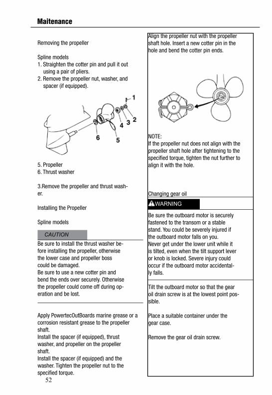
Removing the propeller
Spline models1. Straighten the cotter pin and pull it out using a pair of pliers.2. Remove the propeller nut, washer, and spacer (if equipped).
5. Propeller6. Thrust washer
3.Remove the propeller and thrust wash-er.
Installing the Propeller
Spline models
Be sure to install the thrust washer be-fore installing the propeller, otherwisethe lower case and propeller bosscould be damaged.Be sure to use a new cotter pin andbend the ends over securely. Otherwisethe propeller could come off during op-eration and be lost.
Apply PowertecOutBoards marine grease or a corrosion resistant grease to the propellershaft.Install the spacer (if equipped), thrustwasher, and propeller on the propellershaft.Install the spacer (if equipped) and thewasher. Tighten the propeller nut to thespecified torque.
CAUTION
WARNING
Maitenance
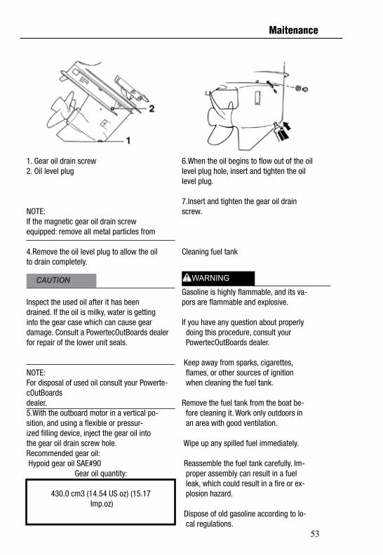
53
6.When the oil begins to flow out of the oillevel plug hole, insert and tighten the oillevel plug.
7.Insert and tighten the gear oil drainscrew.
Cleaning fuel tank
Gasoline is highly flammable, and its va-pors are flammable and explosive.
If you have any question about properly doing this procedure, consult your PowertecOutBoards dealer.
Keep away from sparks, cigarettes, flames, or other sources of ignition when cleaning the fuel tank.
Remove the fuel tank from the boat be- fore cleaning it. Work only outdoors in an area with good ventilation.
Wipe up any spilled fuel immediately.
Reassemble the fuel tank carefully. Im- proper assembly can result in a fuel leak, which could result in a fire or ex- plosion hazard.
Dispose of old gasoline according to lo- cal regulations.
1. Gear oil drain screw2. Oil level plug
NOTE:If the magnetic gear oil drain screwequipped: remove all metal particles from
4.Remove the oil level plug to allow the oilto drain completely.
Inspect the used oil after it has beendrained. If the oil is milky, water is gettinginto the gear case which can cause geardamage. Consult a PowertecOutBoards dealer for repair of the lower unit seals.
NOTE:For disposal of used oil consult your Powerte-cOutBoardsdealer.5.With the outboard motor in a vertical po-sition, and using a flexible or pressur-ized filling device, inject the gear oil intothe gear oil drain screw hole.Recommended gear oil: Hypoid gear oil SAE#90
Gear oil quantity:
430.0 cm3 (14.54 US oz) (15.17 Imp.oz)
CAUTION WARNING
Maitenance
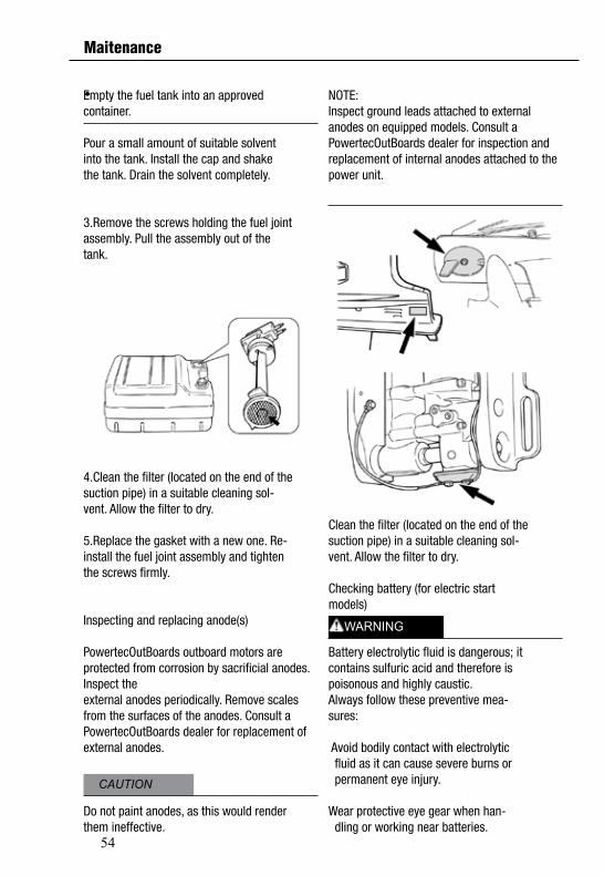
54
NOTE:Inspect ground leads attached to externalanodes on equipped models. Consult aPowertecOutBoards dealer for inspection and replacement of internal anodes attached to the power unit.
Clean the filter (located on the end of thesuction pipe) in a suitable cleaning sol-vent. Allow the filter to dry.
Checking battery (for electric startmodels)
Battery electrolytic fluid is dangerous; itcontains sulfuric acid and therefore ispoisonous and highly caustic.Always follow these preventive mea-sures:
Avoid bodily contact with electrolytic fluid as it can cause severe burns or permanent eye injury. Wear protective eye gear when han- dling or working near batteries.
Empty the fuel tank into an approvedcontainer.
Pour a small amount of suitable solventinto the tank. Install the cap and shakethe tank. Drain the solvent completely.
3.Remove the screws holding the fuel jointassembly. Pull the assembly out of thetank.
4.Clean the filter (located on the end of thesuction pipe) in a suitable cleaning sol-vent. Allow the filter to dry.
5.Replace the gasket with a new one. Re-install the fuel joint assembly and tightenthe screws firmly.
Inspecting and replacing anode(s)
PowertecOutBoards outboard motors are protected from corrosion by sacrificial anodes. Inspect theexternal anodes periodically. Remove scalesfrom the surfaces of the anodes. Consult aPowertecOutBoards dealer for replacement of external anodes.
Do not paint anodes, as this would renderthem ineffective.
CAUTION
WARNING
Maitenance
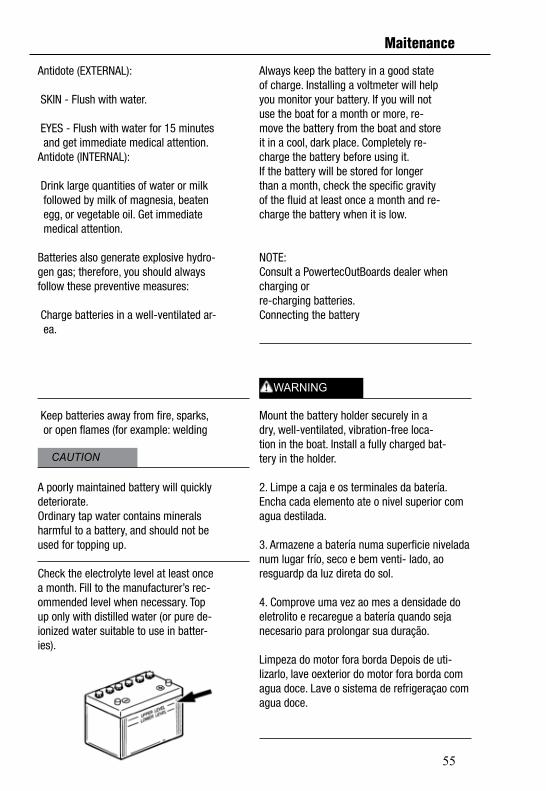
55
Always keep the battery in a good stateof charge. Installing a voltmeter will helpyou monitor your battery. If you will notuse the boat for a month or more, re-move the battery from the boat and storeit in a cool, dark place. Completely re-charge the battery before using it.If the battery will be stored for longerthan a month, check the specific gravityof the fluid at least once a month and re-charge the battery when it is low.
NOTE:Consult a PowertecOutBoards dealer when charging orre-charging batteries.Connecting the battery
Mount the battery holder securely in adry, well-ventilated, vibration-free loca-tion in the boat. Install a fully charged bat-tery in the holder.
2. Limpe a caja e os terminales da batería. Encha cada elemento ate o nivel superior com agua destilada.
3. Armazene a batería numa superficie nivelada num lugar frío, seco e bem venti- lado, ao resguardp da luz direta do sol.
4. Comprove uma vez ao mes a densidade do eletrolito e recaregue a batería quando seja necesario para prolongar sua duração.
Limpeza do motor fora borda Depois de uti-lizarlo, lave oexterior do motor fora borda com agua doce. Lave o sistema de refrigeraçao com agua doce.
Antidote (EXTERNAL):
SKIN - Flush with water.
EYES - Flush with water for 15 minutes and get immediate medical attention.Antidote (INTERNAL):
Drink large quantities of water or milk followed by milk of magnesia, beaten egg, or vegetable oil. Get immediate medical attention.
Batteries also generate explosive hydro-gen gas; therefore, you should alwaysfollow these preventive measures:
Charge batteries in a well-ventilated ar- ea.
Keep batteries away from fire, sparks, or open flames (for example: welding
A poorly maintained battery will quicklydeteriorate.Ordinary tap water contains mineralsharmful to a battery, and should not beused for topping up.
Check the electrolyte level at least oncea month. Fill to the manufacturer’s rec-ommended level when necessary. Topup only with distilled water (or pure de-ionized water suitable to use in batter-ies).
CAUTION
WARNING
Maitenance
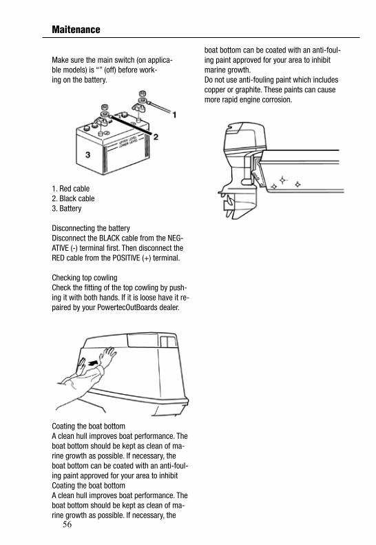
56
boat bottom can be coated with an anti-foul-ing paint approved for your area to inhibit marine growth. Do not use anti-fouling paint which includescopper or graphite. These paints can causemore rapid engine corrosion.
Make sure the main switch (on applica-ble models) is “” (off) before work-ing on the battery.
1. Red cable2. Black cable3. Battery
Disconnecting the batteryDisconnect the BLACK cable from the NEG-ATIVE (-) terminal first. Then disconnect theRED cable from the POSITIVE (+) terminal.
Checking top cowlingCheck the fitting of the top cowling by push-ing it with both hands. If it is loose have it re-paired by your PowertecOutBoards dealer.
Coating the boat bottomA clean hull improves boat performance. Theboat bottom should be kept as clean of ma-rine growth as possible. If necessary, theboat bottom can be coated with an anti-foul-ing paint approved for your area to inhibitCoating the boat bottomA clean hull improves boat performance. Theboat bottom should be kept as clean of ma-rine growth as possible. If necessary, the
Maitenance
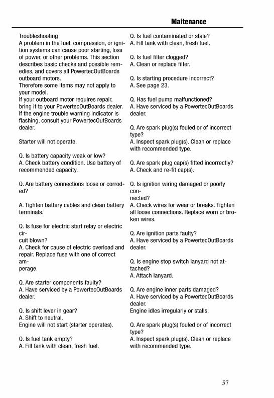
57
Q. Is fuel contaminated or stale?A. Fill tank with clean, fresh fuel.
Q. Is fuel filter clogged?A. Clean or replace filter.
Q. Is starting procedure incorrect?A. See page 23.
Q. Has fuel pump malfunctioned?A. Have serviced by a PowertecOutBoards dealer.
Q. Are spark plug(s) fouled or of incorrecttype?A. Inspect spark plug(s). Clean or replacewith recommended type.
Q. Are spark plug cap(s) fitted incorrectly?A. Check and re-fit cap(s).
Q. Is ignition wiring damaged or poorly con-nected?A. Check wires for wear or breaks. Tightenall loose connections. Replace worn or bro-ken wires.
Q. Are ignition parts faulty?A. Have serviced by a PowertecOutBoards dealer.
Q. Is engine stop switch lanyard not at-tached?A. Attach lanyard.
Q. Are engine inner parts damaged?A. Have serviced by a PowertecOutBoards dealer.Engine idles irregularly or stalls.
Q. Are spark plug(s) fouled or of incorrecttype?A. Inspect spark plug(s). Clean or replacewith recommended type.
Maitenance
TroubleshootingA problem in the fuel, compression, or igni-tion systems can cause poor starting, loss of power, or other problems. This section describes basic checks and possible rem-edies, and covers all PowertecOutBoards outboard motors. Therefore some items may not apply to your model.If your outboard motor requires repair, bring it to your PowertecOutBoards dealer.If the engine trouble warning indicator isflashing, consult your PowertecOutBoards dealer.
Starter will not operate.
Q. Is battery capacity weak or low?A. Check battery condition. Use battery ofrecommended capacity.
Q. Are battery connections loose or corrod-ed?
A. Tighten battery cables and clean batteryterminals.
Q. Is fuse for electric start relay or electric cir-cuit blown?A. Check for cause of electric overload andrepair. Replace fuse with one of correct am-perage.
Q. Are starter components faulty?A. Have serviced by a PowertecOutBoards dealer.
Q. Is shift lever in gear?A. Shift to neutral.Engine will not start (starter operates).
Q. Is fuel tank empty?A. Fill tank with clean, fresh fuel.
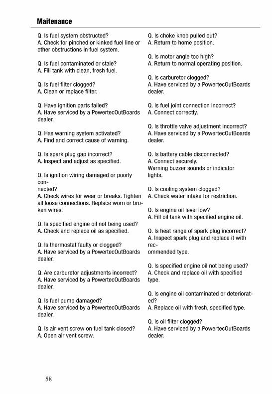
58
Q. Is choke knob pulled out?A. Return to home position.
Q. Is motor angle too high?A. Return to normal operating position.
Q. Is carburetor clogged?A. Have serviced by a PowertecOutBoards dealer.
Q. Is fuel joint connection incorrect?A. Connect correctly.
Q. Is throttle valve adjustment incorrect?A. Have serviced by a PowertecOutBoards dealer.
Q. Is battery cable disconnected?A. Connect securely.Warning buzzer sounds or indicatorlights.
Q. Is cooling system clogged?A. Check water intake for restriction.
Q. Is engine oil level low?A. Fill oil tank with specified engine oil.
Q. Is heat range of spark plug incorrect?A. Inspect spark plug and replace it with rec-ommended type.
Q. Is specified engine oil not being used?A. Check and replace oil with specified type.
Q. Is engine oil contaminated or deteriorat-ed?A. Replace oil with fresh, specified type.
Q. Is oil filter clogged?A. Have serviced by a PowertecOutBoards dealer.
Q. Is fuel system obstructed?A. Check for pinched or kinked fuel line orother obstructions in fuel system.
Q. Is fuel contaminated or stale?A. Fill tank with clean, fresh fuel.
Q. Is fuel filter clogged?A. Clean or replace filter.
Q. Have ignition parts failed?A. Have serviced by a PowertecOutBoards dealer.
Q. Has warning system activated?A. Find and correct cause of warning.
Q. Is spark plug gap incorrect?A. Inspect and adjust as specified.
Q. Is ignition wiring damaged or poorly con-nected?A. Check wires for wear or breaks. Tightenall loose connections. Replace worn or bro-ken wires.
Q. Is specified engine oil not being used?A. Check and replace oil as specified.
Q. Is thermostat faulty or clogged?A. Have serviced by a PowertecOutBoards dealer.
Q. Are carburetor adjustments incorrect?A. Have serviced by a PowertecOutBoards dealer.
Q. Is fuel pump damaged?A. Have serviced by a PowertecOutBoards dealer.
Q. Is air vent screw on fuel tank closed?A. Open air vent screw.
Maitenance
59
Q. Are weeds or other foreign matter tangledon gear housing?A. Remove foreign matter and clean lowerunit.
Q. Is fuel system obstructed?A. Check for pinched or kinked fuel line orother obstructions in fuel system.
Q. Is fuel filter clogged?A. Clean or replace filter.
Q. Is fuel contaminated or stale?A. Fill tank with clean, fresh fuel.
Q. Is spark plug gap incorrect?A. Inspect and adjust as specified.
Q. Is ignition wiring damaged or poorly con-nected?
A. Check wires for wear or breaks. Tightenall loose connections. Replace worn or bro-ken wires.
Q. Have electrical parts failed?A. Have serviced by a PowertecOutBoards dealer.
Q. Is specified fuel not being used?A. Replace fuel with specified type.
Q. Is specified engine oil not being used?A. Check and replace oil with specified type.
Q. Is thermostat faulty or clogged?A. Have serviced by a PowertecOutBoards dealer.
Q. Is air vent screw closed?A. Open the air vent screw.
Q. Is fuel pump damaged?A. Have serviced by a PowertecOutBoards dealer.
Q. Has oil feed/injection pump malfunc-tioned?A. Have serviced by a PowertecOutBoards dealer.
Q. Is load on boat improperly distributed?A. Distribute load to place boat on an evenplane.
Q. Is water pump or thermostat faulty?A. Have serviced by a PowertecOutBoards dealer.
Q. Is there excess water in fuel filter cup?A. Drain filter cup.Engine power loss.
Q. Is propeller damaged?A. Have propeller repaired or replaced.
Q. Is propeller pitch or diameter incorrect?A. Install correct propeller to operate out-board at its recommended speed (r/min)range.
Q. Is trim angle incorrect?A. Adjust trim angle to achieve most ef-ficientoperation.
Q. Is motor mounted at incorrect height ontransom?A. Have motor adjusted to proper transomheight.
Q. Has warning system activated?A. Find and correct cause of warning.
Q. Is boat bottom fouled with marine growth?A. Clean boat bottom.
Q. Are spark plug(s) fouled or of incorrecttype?A. Inspect spark plug(s). Clean or replacewith recommended type.
Maitenance
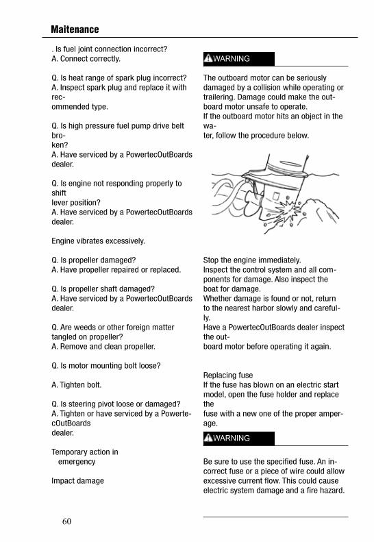
60
The outboard motor can be seriouslydamaged by a collision while operating ortrailering. Damage could make the out-board motor unsafe to operate.If the outboard motor hits an object in the wa-ter, follow the procedure below.
Stop the engine immediately.Inspect the control system and all com-ponents for damage. Also inspect theboat for damage.Whether damage is found or not, returnto the nearest harbor slowly and careful-ly.Have a PowertecOutBoards dealer inspect the out-board motor before operating it again.
Replacing fuseIf the fuse has blown on an electric startmodel, open the fuse holder and replace thefuse with a new one of the proper amper-age.
Be sure to use the specified fuse. An in-correct fuse or a piece of wire could allowexcessive current flow. This could causeelectric system damage and a fire hazard.
. Is fuel joint connection incorrect?A. Connect correctly.
Q. Is heat range of spark plug incorrect?A. Inspect spark plug and replace it with rec-ommended type.
Q. Is high pressure fuel pump drive belt bro-ken?A. Have serviced by a PowertecOutBoards dealer.
Q. Is engine not responding properly to shiftlever position?A. Have serviced by a PowertecOutBoards dealer.
Engine vibrates excessively.
Q. Is propeller damaged?A. Have propeller repaired or replaced.
Q. Is propeller shaft damaged?A. Have serviced by a PowertecOutBoards dealer.
Q. Are weeds or other foreign matter tangled on propeller?A. Remove and clean propeller.
Q. Is motor mounting bolt loose?
A. Tighten bolt.
Q. Is steering pivot loose or damaged?A. Tighten or have serviced by a Powerte-cOutBoardsdealer.
Temporary action in emergency
Impact damage
WARNING
WARNING
Maitenance
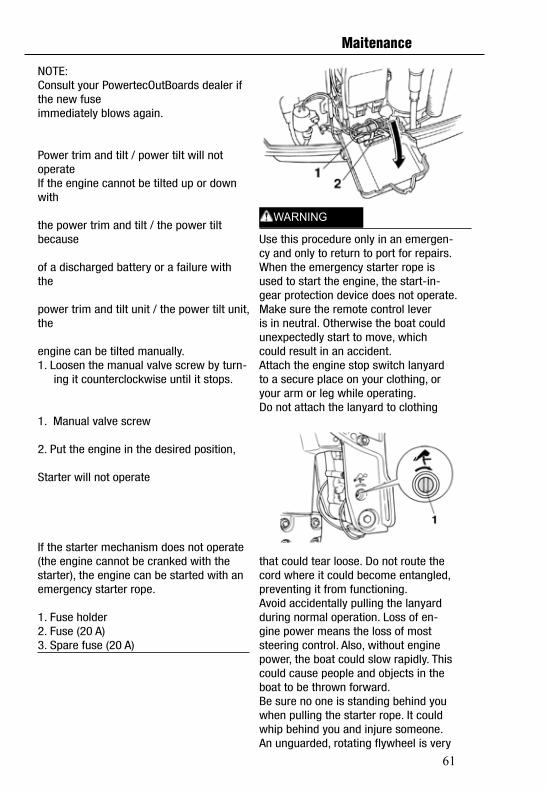
61
Use this procedure only in an emergen-cy and only to return to port for repairs.When the emergency starter rope isused to start the engine, the start-in-gear protection device does not operate. Make sure the remote control leveris in neutral. Otherwise the boat couldunexpectedly start to move, whichcould result in an accident.Attach the engine stop switch lanyardto a secure place on your clothing, oryour arm or leg while operating.Do not attach the lanyard to clothing
that could tear loose. Do not route thecord where it could become entangled,preventing it from functioning.Avoid accidentally pulling the lanyardduring normal operation. Loss of en-gine power means the loss of moststeering control. Also, without enginepower, the boat could slow rapidly. Thiscould cause people and objects in theboat to be thrown forward.Be sure no one is standing behind youwhen pulling the starter rope. It couldwhip behind you and injure someone.An unguarded, rotating flywheel is very
NOTE:Consult your PowertecOutBoards dealer if the new fuseimmediately blows again.
Power trim and tilt / power tilt will notoperateIf the engine cannot be tilted up or down with
the power trim and tilt / the power tilt because
of a discharged battery or a failure with the
power trim and tilt unit / the power tilt unit, the
engine can be tilted manually.1. Loosen the manual valve screw by turn- ing it counterclockwise until it stops.
1. Manual valve screw
2. Put the engine in the desired position,
Starter will not operate
If the starter mechanism does not operate(the engine cannot be cranked with the starter), the engine can be started with an emergency starter rope.
1. Fuse holder2. Fuse (20 A)3. Spare fuse (20 A)
WARNING
Maitenance
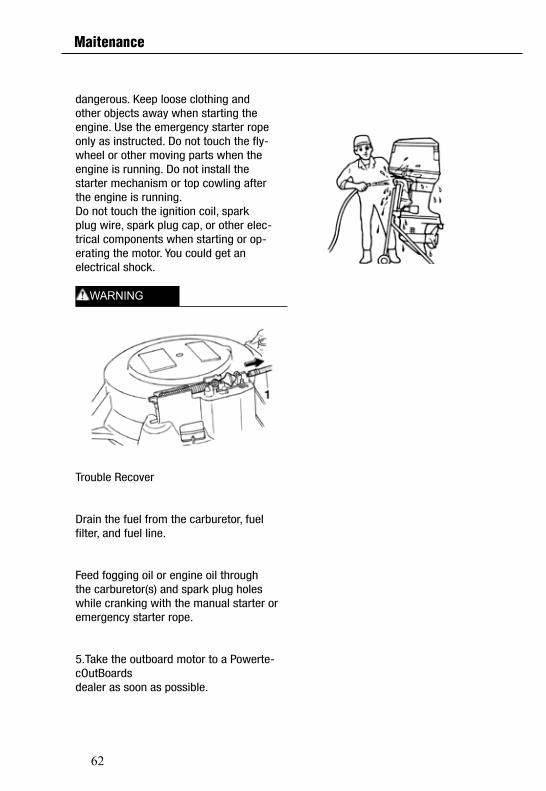
62
dangerous. Keep loose clothing andother objects away when starting theengine. Use the emergency starter ropeonly as instructed. Do not touch the fly-wheel or other moving parts when theengine is running. Do not install thestarter mechanism or top cowling afterthe engine is running.Do not touch the ignition coil, sparkplug wire, spark plug cap, or other elec-trical components when starting or op-erating the motor. You could get anelectrical shock.
Trouble Recover
Drain the fuel from the carburetor, fuelfilter, and fuel line.
Feed fogging oil or engine oil throughthe carburetor(s) and spark plug holeswhile cranking with the manual starter oremergency starter rope.
5.Take the outboard motor to a Powerte-cOutBoardsdealer as soon as possible.
WARNING
Maitenance