Embed Size (px)
Citation preview
Overview of theH-IIA Launch Vehicle No.8
(H-IIA F8)
Japan Aerospace Exploration Agency (JAXA)Independent Administrative Agency
H-IIA Launch Vehicle
Liquid oxygen and hydrogen are used as propellant for both the first and second stages.
Based on technology acquired by the development of the H-II, high reliability is maintained while cost reduction was achieved and the H-IIA family was formed with variations by attaching solid rocket boosters and solid strap-on boosters onto the standard H-IIA.
Various launch needs can be met by choosing an appropriate type of payload fairing and payload attach fitting (PAF) according to the number and size of (a) satellite(s).
Since its maiden flight in Aug. 2001, JAXA has successfully launched five H-IIA launch vehicles. However, in Nov. 2003, the sixth fight failed. In Feb. 2005, the H-IIA F7, the return-to-flight mission, was successfully launched.
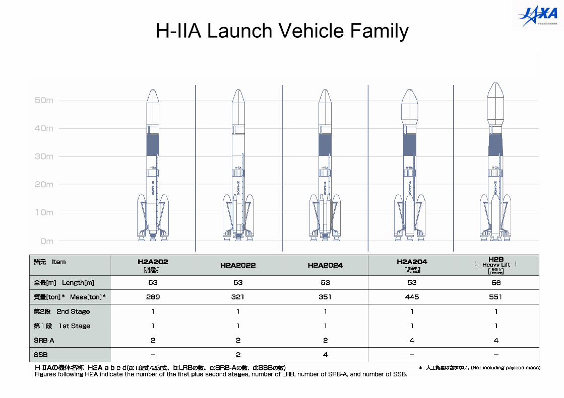
H-IIA Launch Vehicle Family
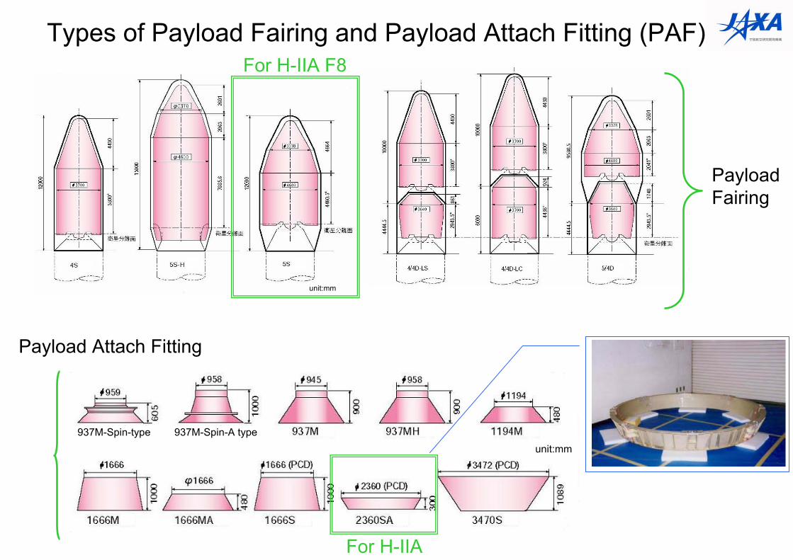
For H-IIA F8
Payload Fairing
For H-IIA
Payload Attach Fitting
Types of Payload Fairing and Payload Attach Fitting (PAF)
unit:mm
unit:mm
937M-Spin-A type937M-Spin-type
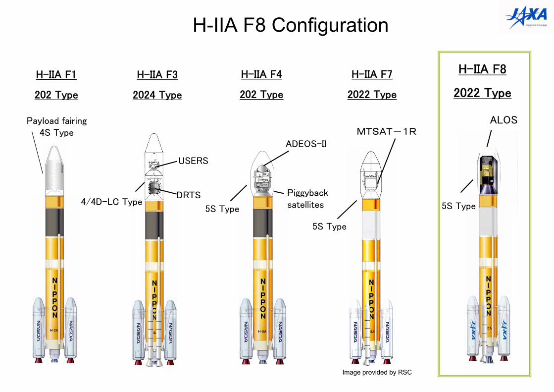
H-IIA F8 Configuration
H-IIA F1
202 Type
H-IIA F4
202 Type
Payload fairing4S Type
H-IIA F3
2024 Type
H-IIA F7
2022 Type
H-IIA F8
2022 Type
USERS
DRTS4/4D-LC Type
ADEOS-II
5S Type 5S Type
ALOSMTSAT-1R
5S Type
Image provided by RSC
Piggyback satellites
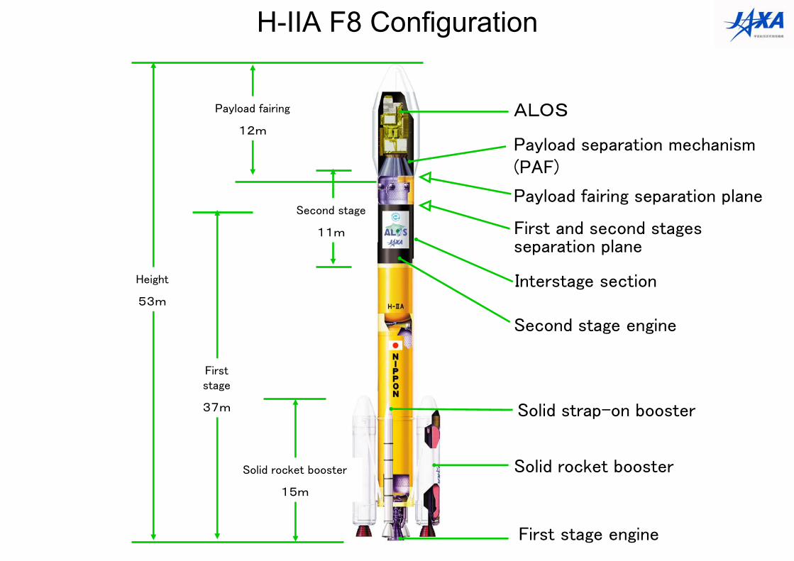
First stage engine
Second stage engine
Solid rocket booster
First and second stages separation plane
Interstage section
Payload fairing separation plane
ALOSPayload fairing
12m
Solid rocket booster
15m
First stage
37m
Height
53m
H-IIA F8 Configuration
Payload separation mechanism (PAF)
Solid strap-on booster
Second stage
11m
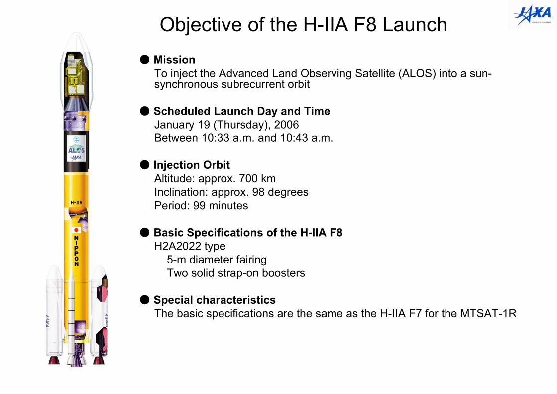
Objective of the H-IIA F8 Launch● Mission
To inject the Advanced Land Observing Satellite (ALOS) into a sun-synchronous subrecurrent orbit
● Scheduled Launch Day and TimeJanuary 19 (Thursday), 2006Between 10:33 a.m. and 10:43 a.m.
● Injection OrbitAltitude: approx. 700 kmInclination: approx. 98 degreesPeriod: 99 minutes
● Basic Specifications of the H-IIA F8H2A2022 type
5-m diameter fairingTwo solid strap-on boosters
● Special characteristicsThe basic specifications are the same as the H-IIA F7 for the MTSAT-1R
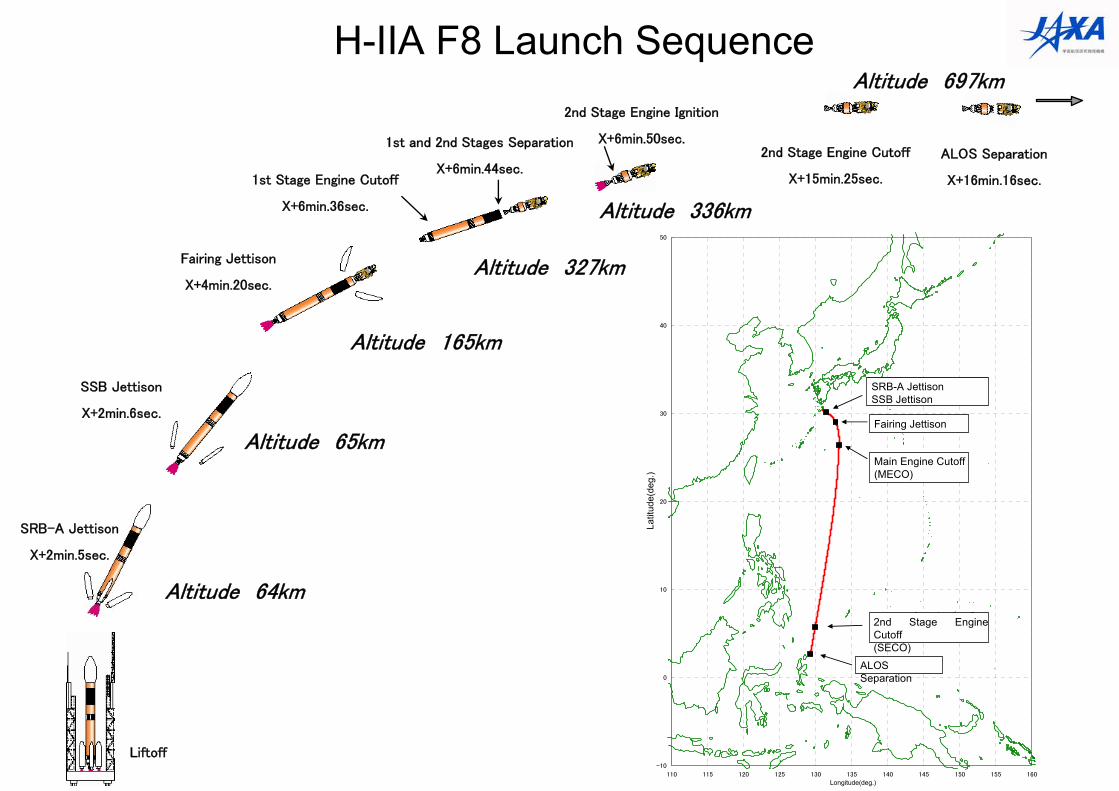
H-IIA F8 Launch Sequence
Liftoff
Altitude 64km
SRB-A Jettison
X+2min.5sec.
Altitude 165km
1st Stage Engine Cutoff
X+6min.36sec.
2nd Stage Engine Ignition
X+6min.50sec.
Altitude 327km
1st and 2nd Stages Separation
X+6min.44sec.2nd Stage Engine Cutoff
X+15min.25sec.
ALOS Separation
X+16min.16sec.
Altitude 697km
Fairing Jettison
X+4min.20sec.
Altitude 65km
SSB Jettison
X+2min.6sec.
-10
0
10
20
30
40
50
110 115 120 125 130 135 140 145 150 155 160
経度[東経,度]
地理
緯度
[北緯
,度
]
固体ロケットブースタ分離固体補助ロケット分離
衛星フェアリング分離
主エンジン燃焼終了(MECO)
第2段エンジン燃焼終了(SECO)
ALOS分離
Altitude 336km
Main Engine Cutoff(MECO)
Fairing Jettison
SRB-A JettisonSSB Jettison
2nd Stage Engine Cutoff(SECO)
ALOS Separation
Longitude(deg.)
Latit
ude(
deg.
)
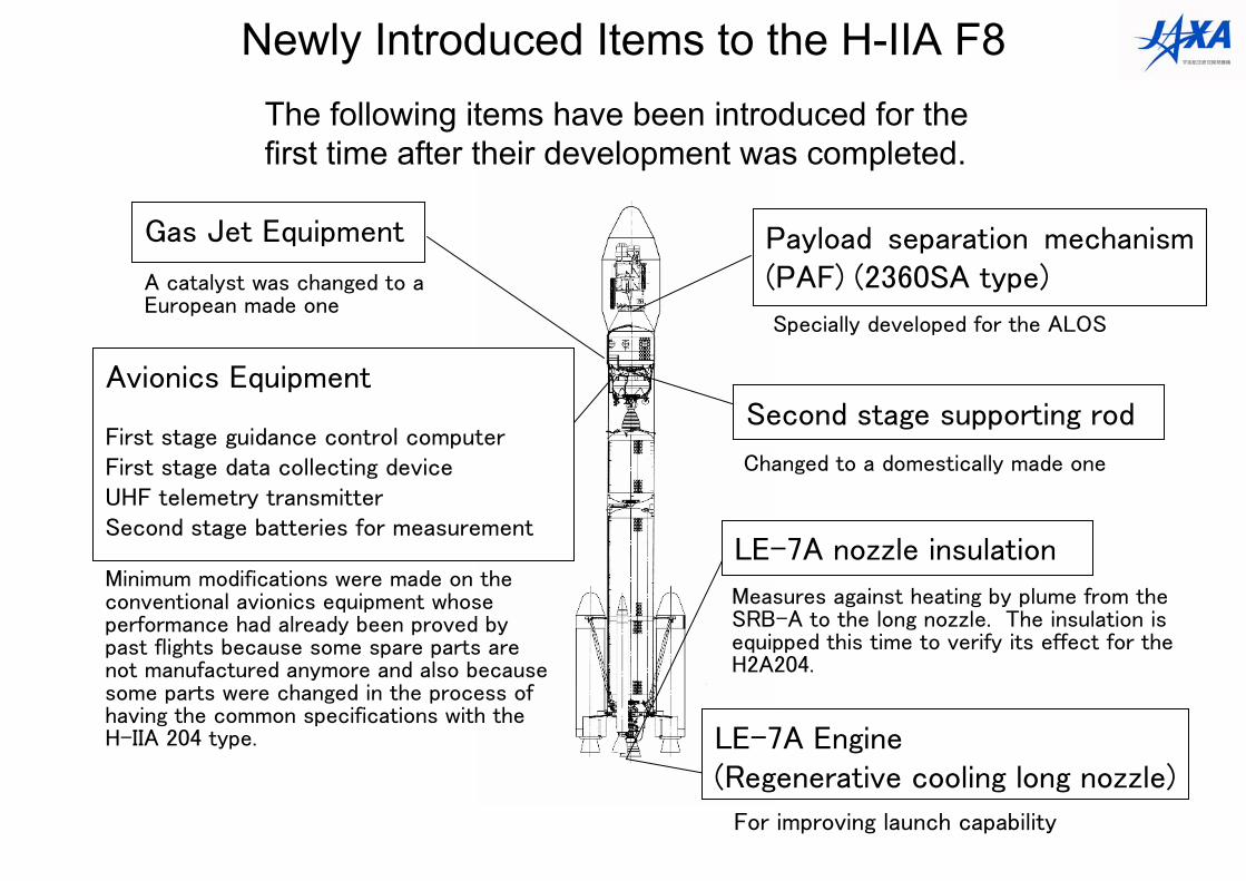
Payload separation mechanism (PAF) (2360SA type)
Gas Jet Equipment
Avionics Equipment
First stage guidance control computerFirst stage data collecting deviceUHF telemetry transmitterSecond stage batteries for measurement
A catalyst was changed to a European made one
LE-7A Engine (Regenerative cooling long nozzle)
Second stage supporting rod
LE-7A nozzle insulation
Measures against heating by plume from the SRB-A to the long nozzle. The insulation is equipped this time to verify its effect for the H2A204.
For improving launch capability
Changed to a domestically made one
Specially developed for the ALOS
Minimum modifications were made on the conventional avionics equipment whose performance had already been proved by past flights because some spare parts are not manufactured anymore and also because some parts were changed in the process of having the common specifications with the H-IIA 204 type.
The following items have been introduced for the first time after their development was completed.
Newly Introduced Items to the H-IIA F8
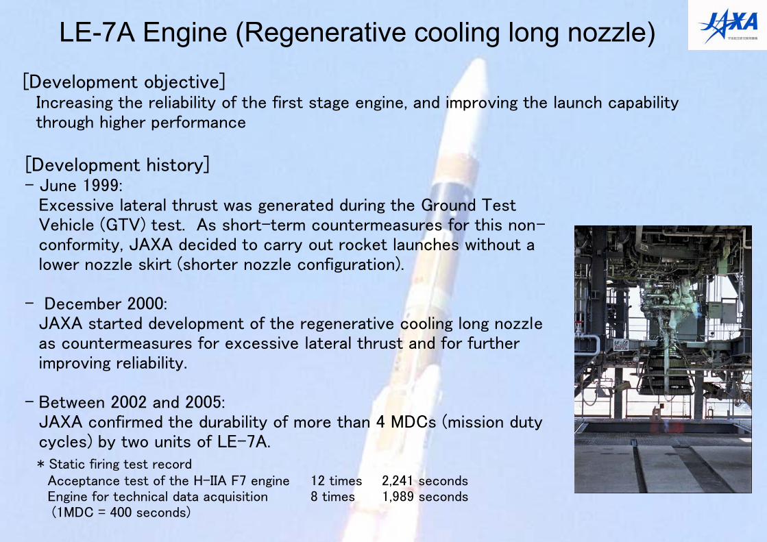
[Development objective]Increasing the reliability of the first stage engine, and improving the launch capability through higher performance
LE-7A Engine (Regenerative cooling long nozzle)
[Development history]- June 1999:
Excessive lateral thrust was generated during the Ground Test Vehicle (GTV) test. As short-term countermeasures for this non-conformity, JAXA decided to carry out rocket launches without a lower nozzle skirt (shorter nozzle configuration).
- December 2000:JAXA started development of the regenerative cooling long nozzleas countermeasures for excessive lateral thrust and for further improving reliability.
- Between 2002 and 2005:JAXA confirmed the durability of more than 4 MDCs (mission duty cycles) by two units of LE-7A.* Static firing test record
Acceptance test of the H-IIA F7 engine 12 times 2,241 secondsEngine for technical data acquisition 8 times 1,989 seconds(1MDC = 400 seconds)
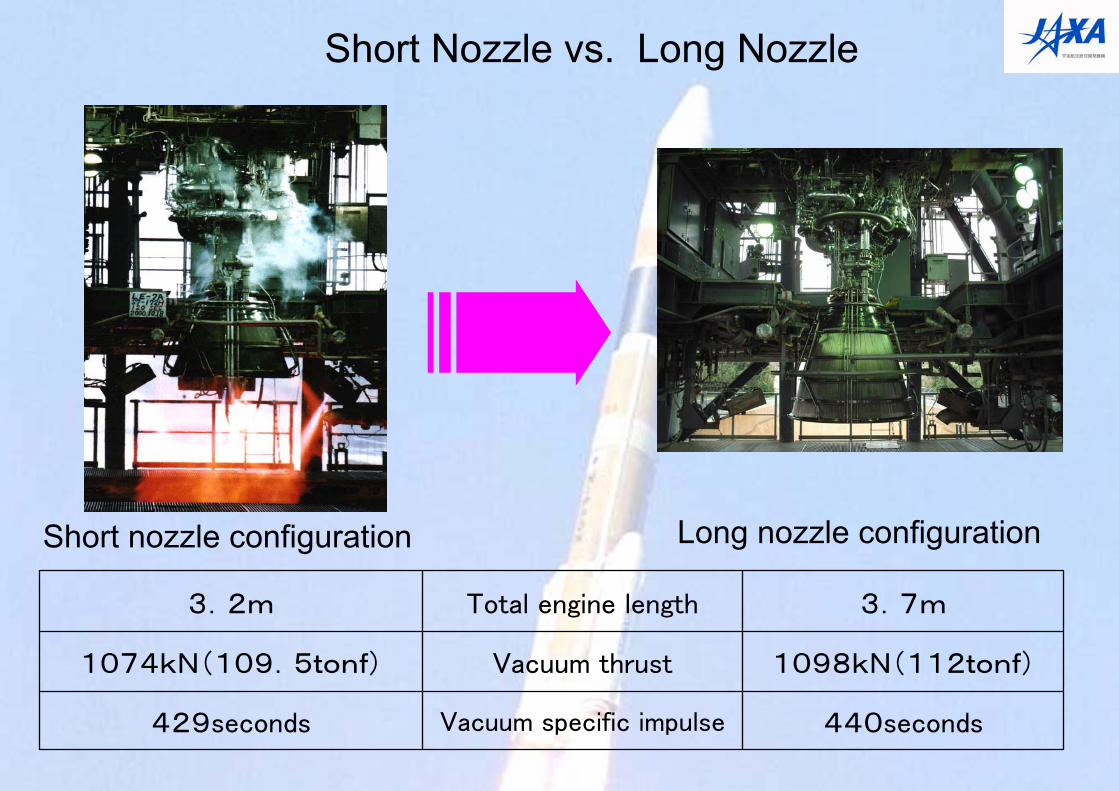
Short Nozzle vs. Long Nozzle
440secondsVacuum specific impulse429seconds
1098kN(112tonf)Vacuum thrust1074kN(109.5tonf)
3.7mTotal engine length3.2m
Short nozzle configuration Long nozzle configuration
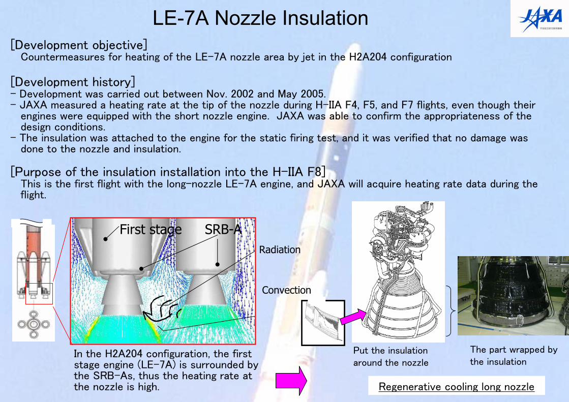
LE-7A Nozzle Insulation
SRB-AFirst stageRadiation
In the H2A204 configuration, the first stage engine (LE-7A) is surrounded by the SRB-As, thus the heating rate at the nozzle is high. Regenerative cooling long nozzle
Put the insulation around the nozzle
The part wrapped by the insulation
[Development objective] Countermeasures for heating of the LE-7A nozzle area by jet in the H2A204 configuration
[Development history]- Development was carried out between Nov. 2002 and May 2005.- JAXA measured a heating rate at the tip of the nozzle during H-IIA F4, F5, and F7 flights, even though their
engines were equipped with the short nozzle engine. JAXA was able to confirm the appropriateness of the design conditions.
- The insulation was attached to the engine for the static firing test, and it was verified that no damage was done to the nozzle and insulation.
[Purpose of the insulation installation into the H-IIA F8] This is the first flight with the long-nozzle LE-7A engine, and JAXA will acquire heating rate data during the flight.
Convection
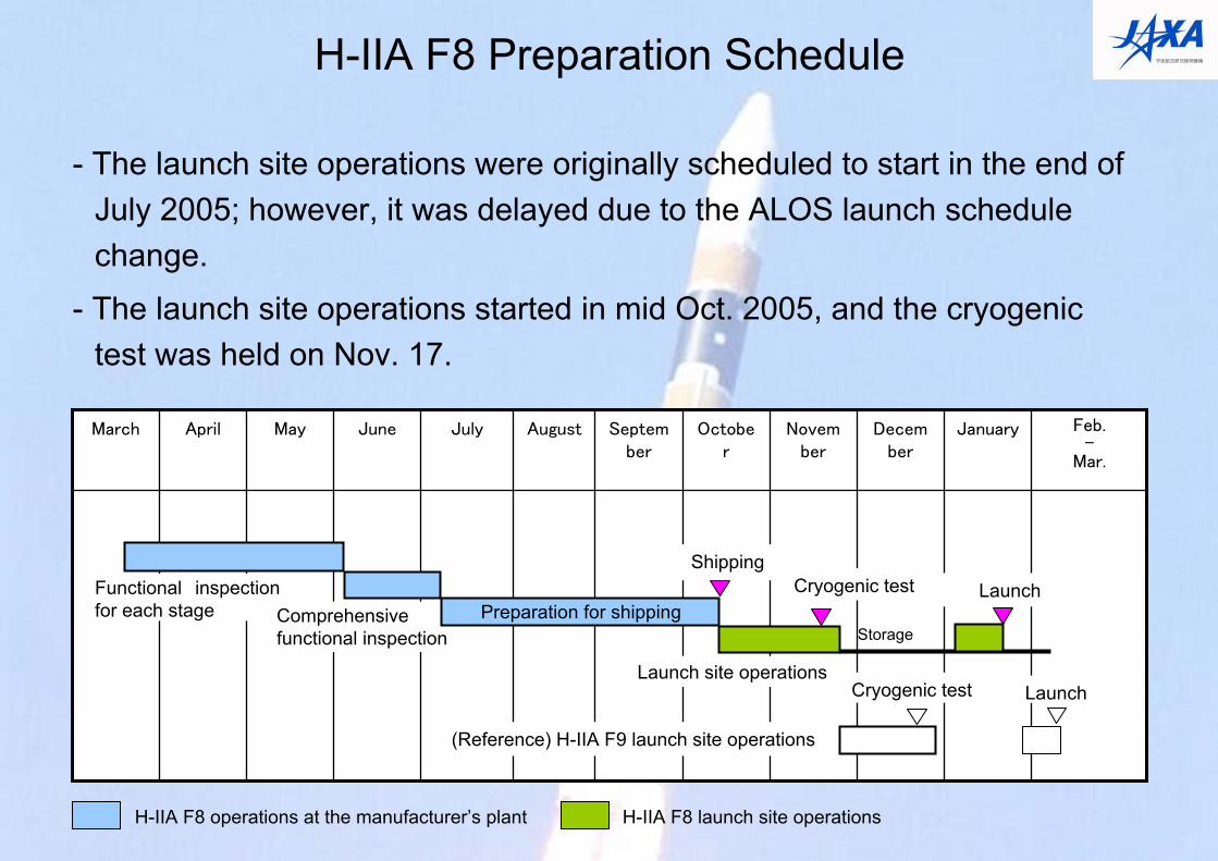
H-IIA F8 Preparation Schedule
- The launch site operations were originally scheduled to start in the end of July 2005; however, it was delayed due to the ALOS launch schedule change.
- The launch site operations started in mid Oct. 2005, and the cryogenic test was held on Nov. 17.
January Feb.-
Mar.
December
November
October
September
AugustJulyJuneMayAprilMarch
ShippingLaunch
Launch site operations
Cryogenic test
Storage
(Reference) H-IIA F9 launch site operations
H-IIA F8 operations at the manufacturer’s plant H-IIA F8 launch site operations
Cryogenic test Launch
Functional inspection for each stage Comprehensive
functional inspectionPreparation for shipping
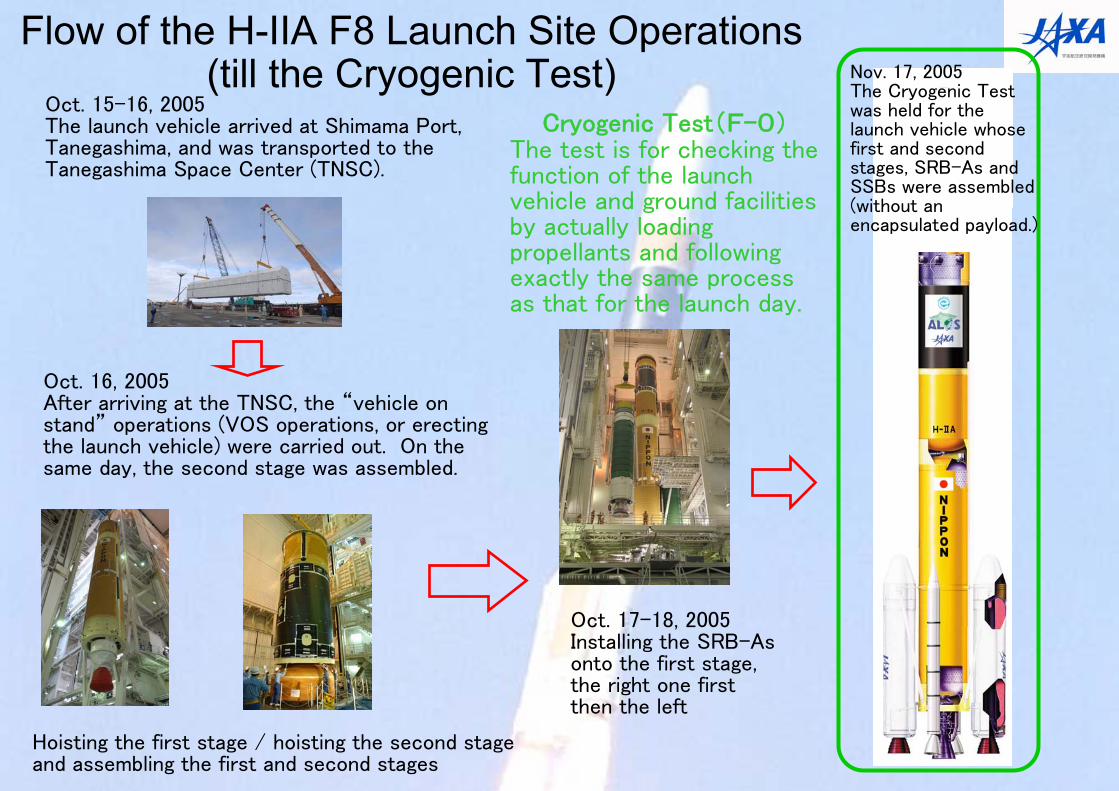
Flow of the H-IIA F8 Launch Site Operations (till the Cryogenic Test)
Oct. 15-16, 2005The launch vehicle arrived at Shimama Port, Tanegashima, and was transported to the Tanegashima Space Center (TNSC).
Oct. 16, 2005After arriving at the TNSC, the “vehicle on stand” operations (VOS operations, or erecting the launch vehicle) were carried out. On the same day, the second stage was assembled.
Hoisting the first stage / hoisting the second stage and assembling the first and second stages
Cryogenic Test(F-0)The test is for checking the function of the launch vehicle and ground facilities by actually loading propellants and following exactly the same process as that for the launch day.
Oct. 17-18, 2005Installing the SRB-As onto the first stage, the right one first then the left
Nov. 17, 2005The Cryogenic Test was held for the launch vehicle whose first and second stages, SRB-As and SSBs were assembled (without an encapsulated payload.)
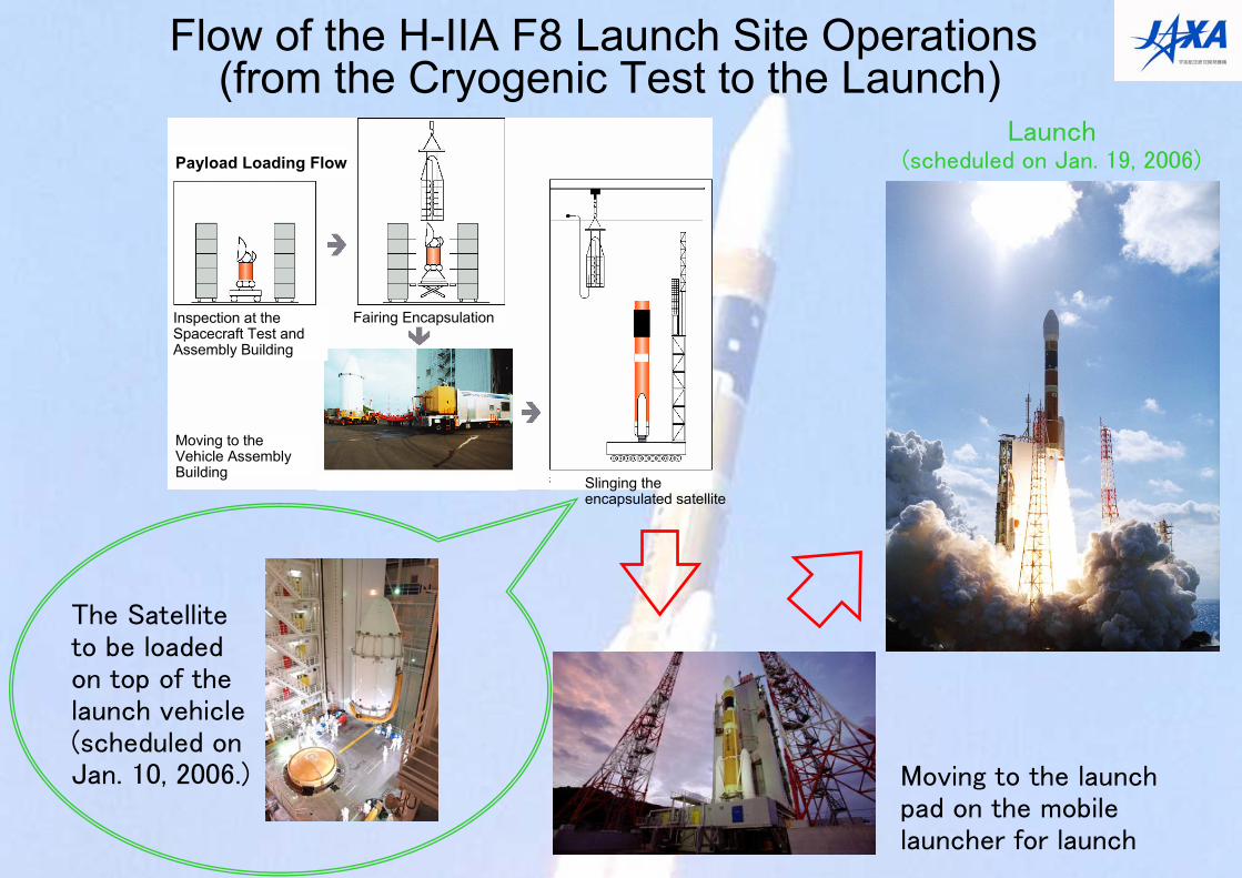
The Satellite to be loaded on top of the launch vehicle (scheduled on Jan. 10, 2006.) Moving to the launch
pad on the mobile launcher for launch
Launch (scheduled on Jan. 19, 2006)
Flow of the H-IIA F8 Launch Site Operations(from the Cryogenic Test to the Launch)
Payload Loading Flow
Inspection at the Spacecraft Test and Assembly Building
Fairing Encapsulation
Moving to the Vehicle Assembly Building
Slinging the encapsulated satellite
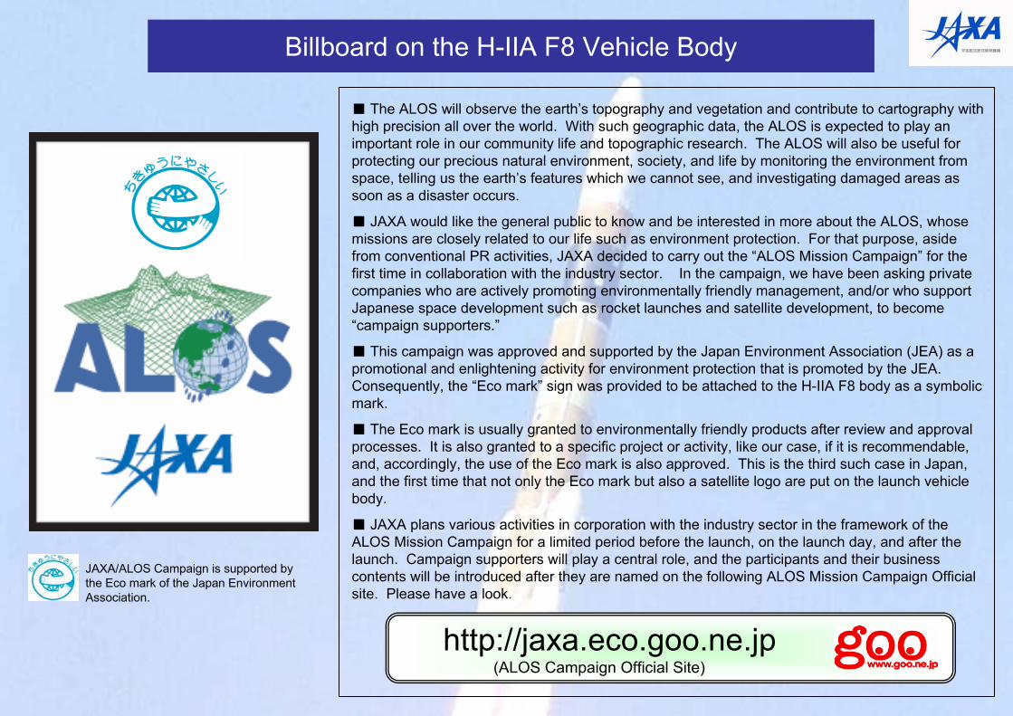
Billboard on the H-IIA F8 Vehicle Body
JAXA/ALOS Campaign is supported by the Eco mark of the Japan Environment Association.
http://jaxa.eco.goo.ne.jp(ALOS Campaign Official Site)
■ The ALOS will observe the earth’s topography and vegetation and contribute to cartography with high precision all over the world. With such geographic data, the ALOS is expected to play an important role in our community life and topographic research. The ALOS will also be useful for protecting our precious natural environment, society, and life by monitoring the environment from space, telling us the earth’s features which we cannot see, and investigating damaged areas as soon as a disaster occurs.
■ JAXA would like the general public to know and be interested in more about the ALOS, whose missions are closely related to our life such as environment protection. For that purpose, aside from conventional PR activities, JAXA decided to carry out the “ALOS Mission Campaign” for the first time in collaboration with the industry sector. In the campaign, we have been asking private companies who are actively promoting environmentally friendly management, and/or who support Japanese space development such as rocket launches and satellite development, to become “campaign supporters.”
■ This campaign was approved and supported by the Japan Environment Association (JEA) as a promotional and enlightening activity for environment protection that is promoted by the JEA. Consequently, the “Eco mark” sign was provided to be attached to the H-IIA F8 body as a symbolic mark.
■ The Eco mark is usually granted to environmentally friendly products after review and approval processes. It is also granted to a specific project or activity, like our case, if it is recommendable, and, accordingly, the use of the Eco mark is also approved. This is the third such case in Japan, and the first time that not only the Eco mark but also a satellite logo are put on the launch vehicle body.
■ JAXA plans various activities in corporation with the industry sector in the framework of the ALOS Mission Campaign for a limited period before the launch, on the launch day, and after the launch. Campaign supporters will play a central role, and the participants and their business contents will be introduced after they are named on the following ALOS Mission Campaign Official site. Please have a look.
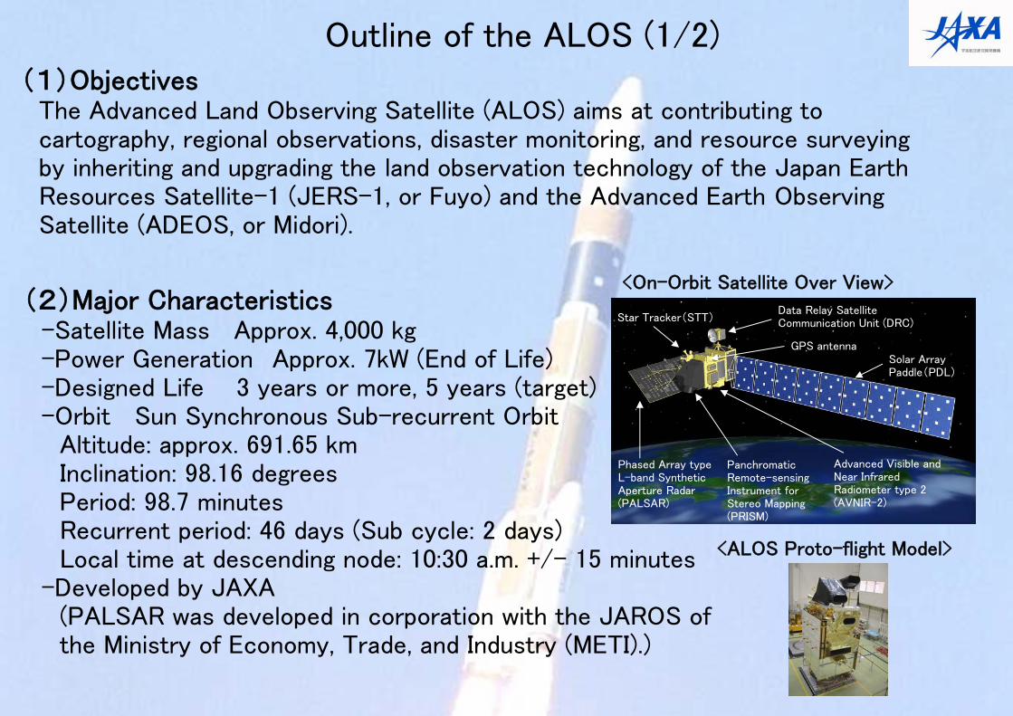
(1)ObjectivesThe Advanced Land Observing Satellite (ALOS) aims at contributing to cartography, regional observations, disaster monitoring, and resource surveying by inheriting and upgrading the land observation technology of the Japan Earth Resources Satellite-1 (JERS-1, or Fuyo) and the Advanced Earth Observing Satellite (ADEOS, or Midori).
Outline of the ALOS (1/2)
(2)Major Characteristics-Satellite Mass Approx. 4,000 kg-Power Generation Approx. 7kW (End of Life)-Designed Life 3 years or more, 5 years (target)-Orbit Sun Synchronous Sub-recurrent Orbit
Altitude: approx. 691.65 kmInclination: 98.16 degreesPeriod: 98.7 minutesRecurrent period: 46 days (Sub cycle: 2 days)Local time at descending node: 10:30 a.m. +/- 15 minutes
-Developed by JAXA(PALSAR was developed in corporation with the JAROS of the Ministry of Economy, Trade, and Industry (METI).)
Advanced Visible and Near Infrared Radiometer type 2 (AVNIR-2)
Panchromatic Remote-sensing Instrument for Stereo Mapping (PRISM)
Phased Array type L-band Synthetic Aperture Radar (PALSAR)
Solar Array Paddle(PDL)
Data Relay Satellite Communication Unit (DRC)Star Tracker(STT)
GPS antenna
<On-Orbit Satellite Over View>
<ALOS Proto-flight Model>
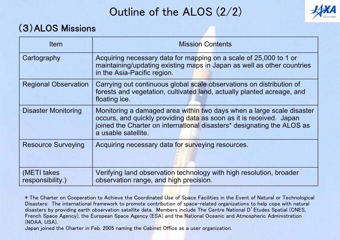
Outline of the ALOS (2/2)
(3)ALOS Missions
Verifying land observation technology with high resolution, broader observation range, and high precision.
(METI takes responsibility.)
Monitoring a damaged area within two days when a large scale disaster occurs, and quickly providing data as soon as it is received. Japan joined the Charter on international disasters* designating the ALOS as a usable satellite.
Disaster Monitoring
Acquiring necessary data for surveying resources.Resource Surveying
Carrying out continuous global scale observations on distribution of forests and vegetation, cultivated land, actually planted acreage, and floating ice.
Regional Observation
Acquiring necessary data for mapping on a scale of 25,000 to 1 or maintaining/updating existing maps in Japan as well as other countries in the Asia-Pacific region.
Mission Contents
Cartography
Item
* The Charter on Cooperation to Achieve the Coordinated Use of Space Facilities in the Event of Natural or Technological Disasters: The international framework to promote contribution of space-related organizations to help cope with natural disasters by providing earth observation satellite data. Members include The Centre National D’Etudes Spatial (CNES, French Space Agency), the European Space Agency (ESA) and the National Oceanic and Atmospheric Administration (NOAA, USA).Japan joined the Charter in Feb. 2005 naming the Cabinet Office as a user organization.
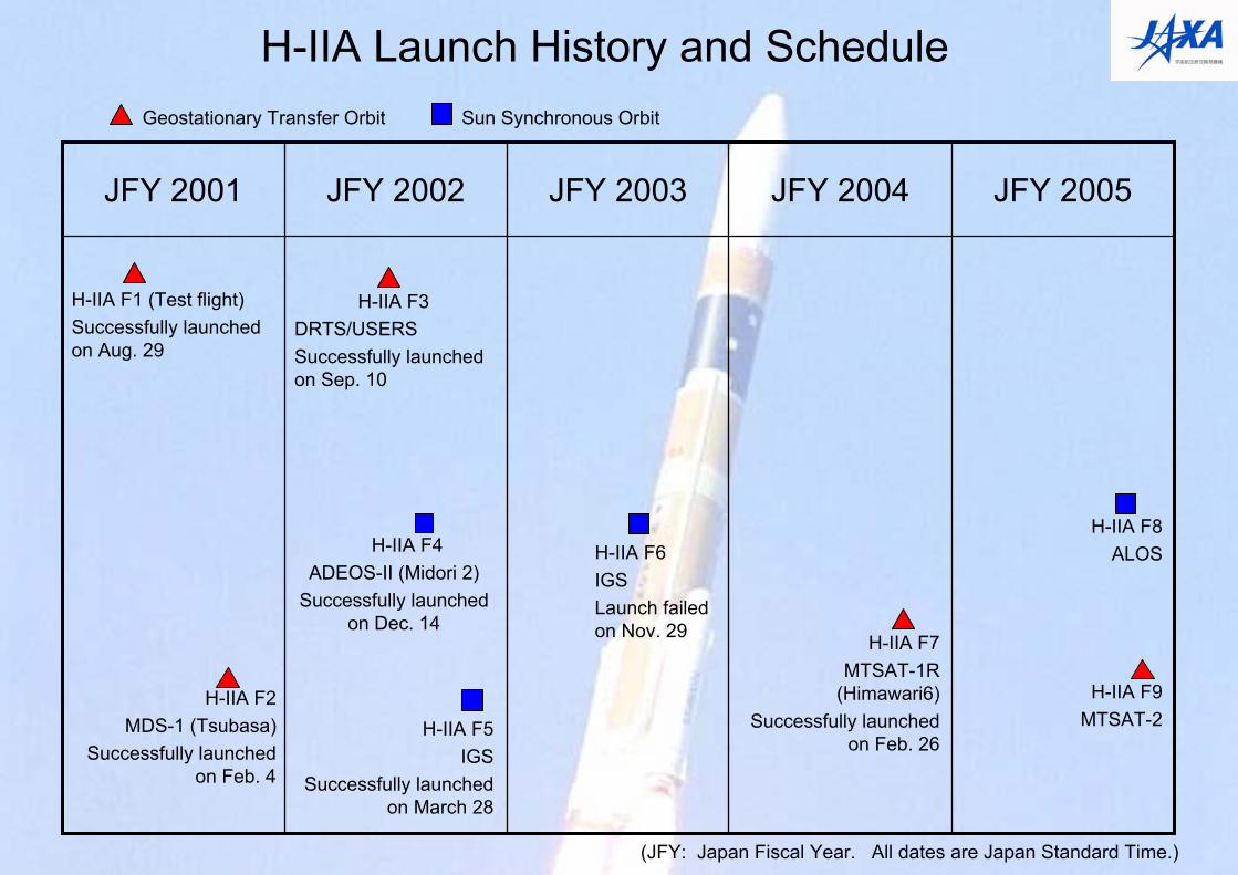
H-IIA Launch History and ScheduleGeostationary Transfer Orbit Sun Synchronous Orbit
JFY 2005JFY 2004JFY 2003JFY 2002JFY 2001
H-IIA F1 (Test flight)Successfully launched on Aug. 29
H-IIA F2MDS-1 (Tsubasa)
Successfully launched on Feb. 4
H-IIA F8ALOS
H-IIA F9MTSAT-2
H-IIA F7MTSAT-1R
(Himawari6)Successfully launched
on Feb. 26
H-IIA F6IGSLaunch failed on Nov. 29
H-IIA F3DRTS/USERSSuccessfully launched on Sep. 10
H-IIA F4ADEOS-II (Midori 2)
Successfully launched on Dec. 14
H-IIA F5IGS
Successfully launched on March 28
(JFY: Japan Fiscal Year. All dates are Japan Standard Time.)
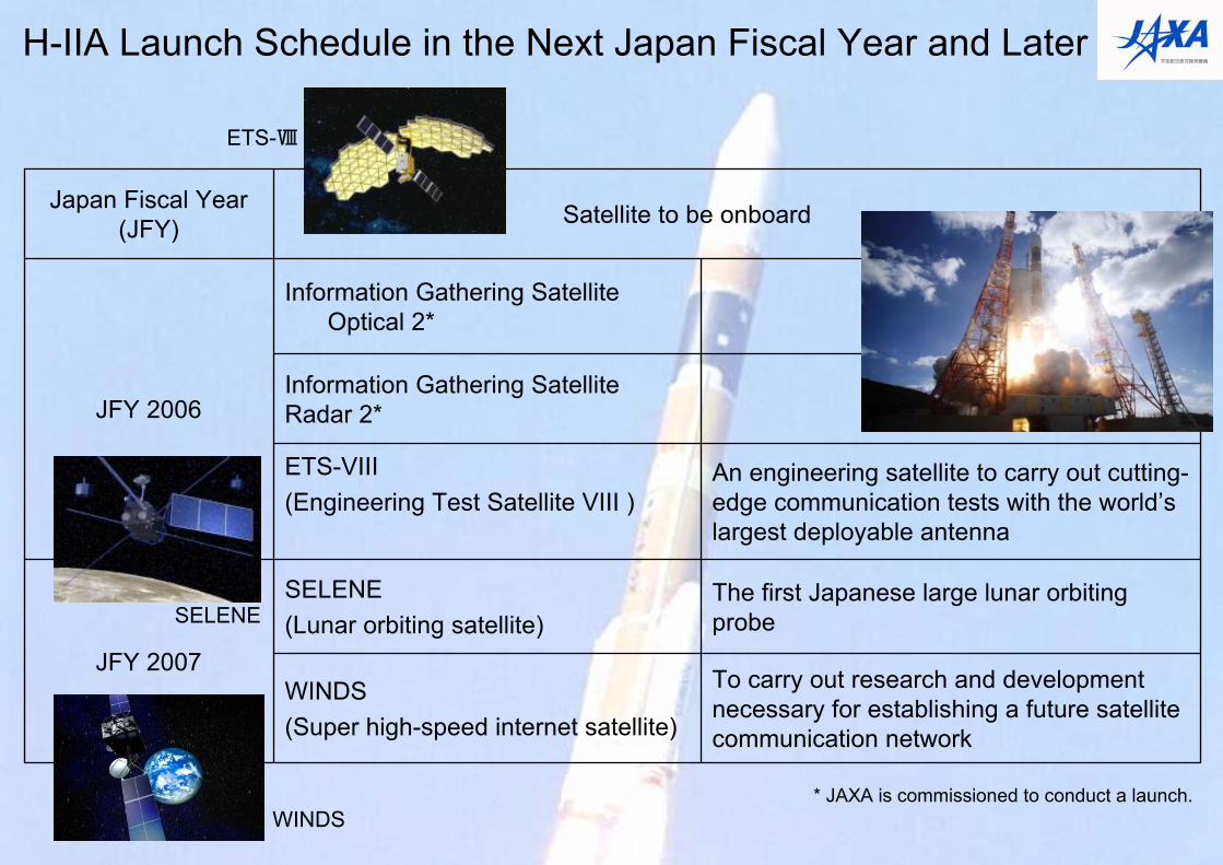
H-IIA Launch Schedule in the Next Japan Fiscal Year and Later
To carry out research and development necessary for establishing a future satellite communication network
WINDS(Super high-speed internet satellite)
The first Japanese large lunar orbiting probe
SELENE(Lunar orbiting satellite)
JFY 2007
An engineering satellite to carry out cutting-edge communication tests with the world’s largest deployable antenna
ETS-VIII(Engineering Test Satellite VIII )
Information Gathering Satellite Radar 2*
Information Gathering Satellite Optical 2*
JFY 2006
Satellite to be onboardJapan Fiscal Year (JFY)
* JAXA is commissioned to conduct a launch.
ETS-Ⅷ
SELENE
WINDS
Reference / Additional Information
- Launch Related Facilities at the Tanegashima Space Center
- H-IIA F6 Launch Failure Cause and Investigation
- Issues Addressed for the H-IIA F7 (Design change of the SRB-A / Thorough review of the launch vehicle)
- H-IIA Launch Vehicle vs. Rockets around the World
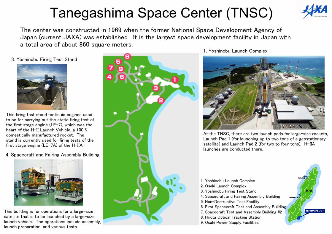
Tanegashima Space Center (TNSC)
At the TNSC, there are two launch pads for large-size rockets, Launch Pad 1 (for launching up to two tons of a geostationary satellite) and Launch Pad 2 (for two to four tons). H-IIA launches are conducted there.
This building is for operations for a large-size satellite that is to be launched by a large-size launch vehicle. The operations include assembly, launch preparation, and various tests.
This firing test stand for liquid engines used to be for carrying out the static firing test of the first stage engine (LE-7), which was the heart of the H-II Launch Vehicle, a 100 % domestically manufactured rocket. The stand is currently used for firing tests of the first stage engine (LE-7A) of the H-IIA.
The center was constructed in 1969 when the former National Space Development Agency of Japan (current JAXA) was established. It is the largest space development facility in Japan with a total area of about 860 square meters.
4. Spacecraft and Fairing Assembly Building
1. Yoshinobu Launch Complex
3. Yoshinobu Firing Test Stand
1. Yoshinobu Launch Complex2. Osaki Launch Complex3. Yoshinobu Firing Test Stand 4. Spacecraft and Fairing Assembly Building 5. Non-Destructive Test Facility6. First Spacecraft Test and Assembly Building 7. Spacecraft Test and Assembly Building #28. Hirota Optical Tracking Station 9. Osaki Power Supply Facilities
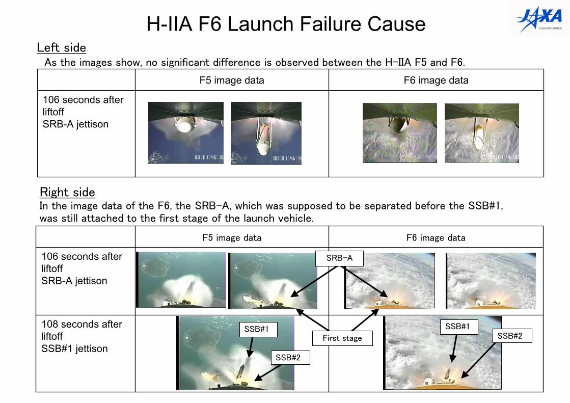
108 seconds after liftoffSSB#1 jettison
106 seconds after liftoffSRB-A jettison
F6 image dataF5 image data
Right sideIn the image data of the F6, the SRB-A, which was supposed to be separated before the SSB#1, was still attached to the first stage of the launch vehicle.
SSB#1SSB#2
106 seconds after liftoffSRB-A jettison
F6 image dataF5 image data
SSB#1
SSB#2
Left sideAs the images show, no significant difference is observed between the H-IIA F5 and F6.
SRB-A
First stage
H-IIA F6 Launch Failure Cause
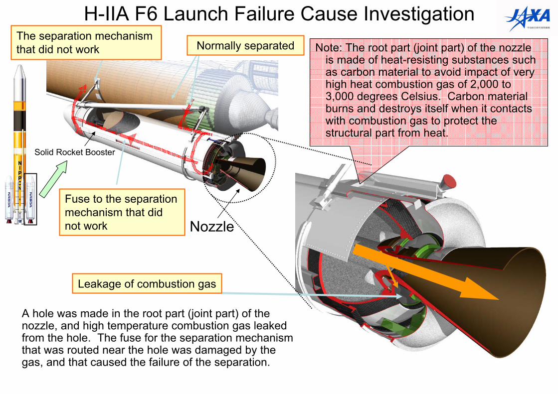
Normally separated
Fuse to the separation mechanism that did not work
Solid Rocket Booster
The separation mechanism that did not work
Nozzle
H-IIA F6 Launch Failure Cause Investigation
A hole was made in the root part (joint part) of the nozzle, and high temperature combustion gas leaked from the hole. The fuse for the separation mechanism that was routed near the hole was damaged by the gas, and that caused the failure of the separation.
Note: The root part (joint part) of the nozzle is made of heat-resisting substances such as carbon material to avoid impact of very high heat combustion gas of 2,000 to 3,000 degrees Celsius. Carbon material burns and destroys itself when it contacts with combustion gas to protect the structural part from heat.
Leakage of combustion gas
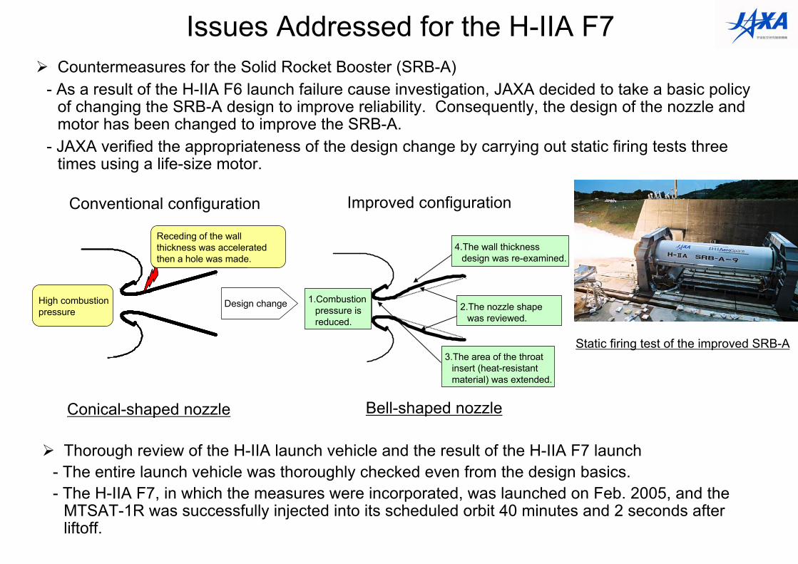
Issues Addressed for the H-IIA F7Countermeasures for the Solid Rocket Booster (SRB-A)
- As a result of the H-IIA F6 launch failure cause investigation, JAXA decided to take a basic policy of changing the SRB-A design to improve reliability. Consequently, the design of the nozzle and motor has been changed to improve the SRB-A.
- JAXA verified the appropriateness of the design change by carrying out static firing tests three times using a life-size motor.
Static firing test of the improved SRB-A
コニカル(円錐)型ノズル(従来型) ベル(釣鐘)型ノズル(改良型)
板厚減少が加速・破孔
高燃焼圧力
板厚減少が加速・破孔
高燃焼圧力
④板厚設計の見直し
①燃焼圧力を下げる
③スロートインサート(耐熱部材)の範囲拡大
②ノズル形状の見直し設計変更
Conical-shaped nozzle Bell-shaped nozzle
Thorough review of the H-IIA launch vehicle and the result of the H-IIA F7 launch- The entire launch vehicle was thoroughly checked even from the design basics.- The H-IIA F7, in which the measures were incorporated, was launched on Feb. 2005, and the
MTSAT-1R was successfully injected into its scheduled orbit 40 minutes and 2 seconds after liftoff.
Improved configurationConventional configuration
High combustion pressure
Receding of the wall thickness was accelerated then a hole was made.
1.Combustion pressure is reduced.
4.The wall thickness design was re-examined.
2.The nozzle shape was reviewed.
3.The area of the throat insert (heat-resistant material) was extended.
Design change
USA Japan
-
-
Nitrogen tetroxide, NTO/Hydrazine
Liquid oxygen/Liquid hydrogen
Solid
6.0
18.0
746
5.4
54
2
Europe
Ariane 5
Ukraine ChinaRussia
Fourth stage
Third stage
Second stage
First stage
Sub booster
---Liquid oxygen
/Liquid hydrogen---
--Liquid oxygen
/KerosineNitrogen tetroxide,
NTO/Hydrazine---
Liquid oxygen/Liquid hydrogen
Nitrogen tetroxide, NTO/Hydrazine
Liquid oxygen/Kerosine
Nitrogen tetroxide, NTO/Hydrazine
Liquid oxygen/Kerosine
Liquid oxygen/Liquid hydrogen
Liquid oxygen/Liquid hydrogen
Liquid oxygen/Liquid hydrogen
Nitrogen tetroxide, NTO/Hydrazine
Liquid oxygen/Kerosine
Nitrogen tetroxide, NTO/Hydrazine
Liquid oxygen/Kerosine
Liquid oxygen/Kerosine
Liquid oxygen/Liquid hydrogen
SolidNitrogen tetroxide, NTO/Hydrazine--
Liquid oxygen/KerosineSolidSolid
Propellant
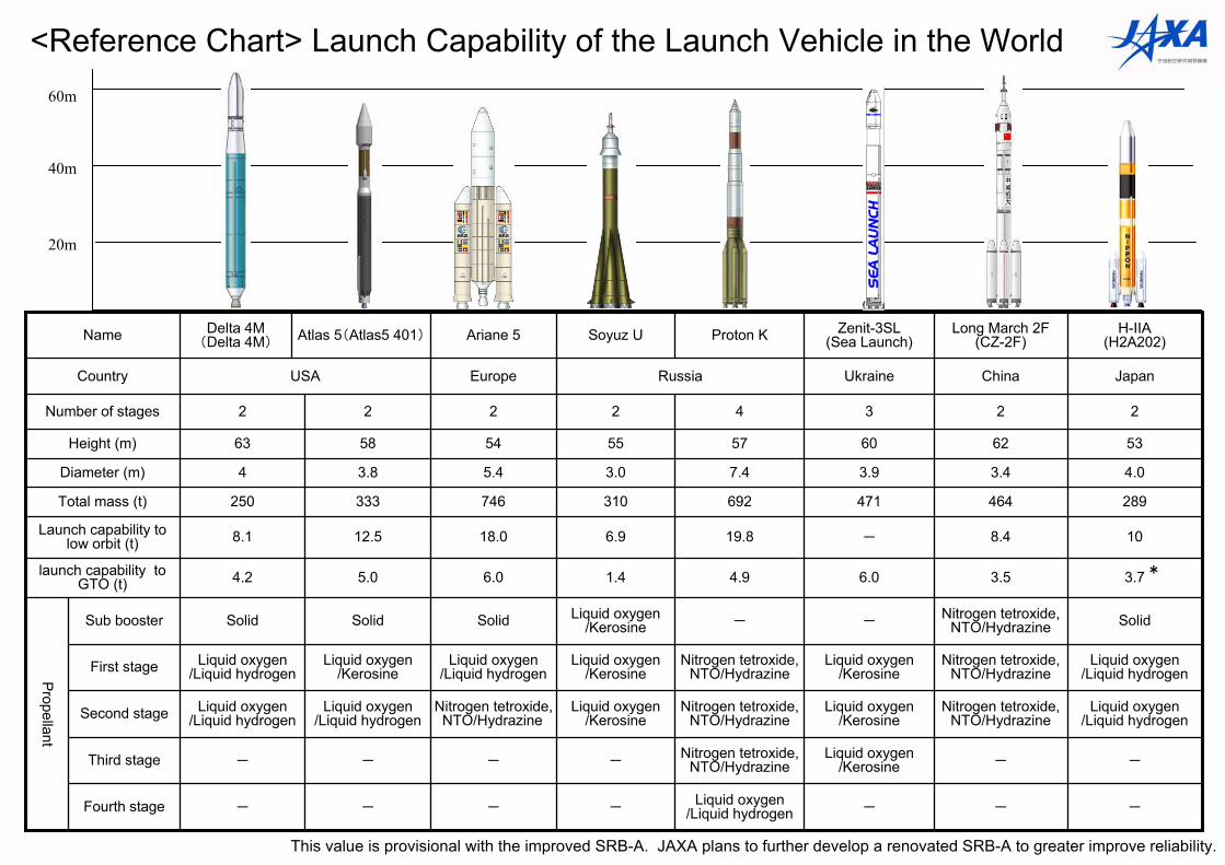
3.73.56.04.91.45.04.2launch capability to GTO (t)
108.4-19.86.912.58.1Launch capability to low orbit (t)
289464471692310333250Total mass (t)
4.03.43.97.43.03.84Diameter (m)
53626057555863Height (m)
2234222Number of stages
Country
H-IIA(H2A202)
Long March 2F(CZ-2F)
Zenit-3SL(Sea Launch)Proton KSoyuz UAtlas 5(Atlas5 401)Delta 4M
(Delta 4M)Name
20m
40m
60m
<Reference Chart> Launch Capability of the Launch Vehicle in the World
This value is provisional with the improved SRB-A. JAXA plans to further develop a renovated SRB-A to greater improve reliability.
*