Embed Size (px)
Citation preview
YET04001
Ver. 4.0
February 2015
H-IIA User's Manual

YET04001 2 Ver. 4.0
Ver. 4.0 3 YET04001
PREFACE
This H-IIA User’s Manual presents information regarding the H-IIA launch vehicle and its
related systems and launch services.
This document contains information for launch services including mission performance
capability, environmental conditions, spacecraft and launch vehicle interface conditions, launch
operations and interface management. A brief description of the H-IIA launch vehicles and the
launch facilities of Tanegashima Space Center is also included. As the H-IIA program is
progressing, this document is subject to change and will be revised periodically.
Requests for further information or inquiries related to this manual or interfaces between
spacecraft and the H-IIA launch system should be addressed to :
Space Systems Business Development Department Business Development Division Integrated Defense & Space Systems Mitsubishi Heavy Industries, Ltd. 16-5, KONAN, 2-CHOME, MINATO-KU, TOKYO, 108-8215 JAPAN Telephone: +81-3-6716-4342 Fax: +81-3-6716-5869 Website: http://h2a.mhi.co.jp/en/index.html
© Mitsubishi Heavy Industries, Ltd. This manual is not allowed to be copied, duplicated, or quoted in part
or whole (including drawings and photographs) without permission from
Mitsubishi Heavy Industries, Ltd.
Preface
YET04001 4 Ver. 4.0
Signature
Version Date Signature
3.0.1 March 2009
3.0.1A July 2009
4.0 February 2015
Ver. 4.0 5 YET04001
TABLE OF CONTENTS
Chapter 1 INTRODUCTION ............................................................................................................ 23
1.1 Purpose ............................................................................................................................................... 23
1.2 MHI Launch services ......................................................................................................................... 23
1.2.1 Description ................................................................................................................................. 23
1.2.2 Definition ................................................................................................................................... 23
1.3 H-IIA Launch System ......................................................................................................................... 26
1.3.1 H-IIA Launch Vehicle Description ............................................................................................ 26
1.3.2 Launch Facilities ........................................................................................................................ 27
1.4 H-IIA Launch System Related Document .......................................................................................... 39
1.4.1 Facility Guide for H-IIA Payload Launch Campaign................................................................. 39
1.4.2 Launch Vehicle Payload Safety Standard .................................................................................. 39
Chapter 2 PERFORMANCE ........................................................................................................... 41
2.1 General ............................................................................................................................................... 41
2.1.1 Mission profile ........................................................................................................................... 41
2.2 Launch performance definition .......................................................................................................... 47
2.2.1 Payload mass .............................................................................................................................. 47
2.2.2 Launch vehicle configurations ................................................................................................... 47
2.2.3 Launch vehicle performance ...................................................................................................... 47
2.3 Geostationary Transfer Orbit (GTO) Mission .................................................................................... 48
2.3.1 Launch capability for dedicated launch ...................................................................................... 48
2.3.2 Launch capability for dual (GTO and GTO) launch .................................................................. 49
2.3.3 Typical orbital parameters .......................................................................................................... 49
2.3.4 Injection accuracies .................................................................................................................... 50
2.3.5 Typical sequence of events ......................................................................................................... 50
2.3.6 Typical trajectory ....................................................................................................................... 50
2.4 Sun Synchronous Orbit (SSO) Mission .............................................................................................. 64
2.4.1 Launch capability ....................................................................................................................... 64
2.4.2 Typical orbital parameters .......................................................................................................... 64
2.4.3 Injection accuracies .................................................................................................................... 64
2.4.4 Typical trajectory ....................................................................................................................... 64
2.5 Low Earth Orbit (LEO) Mission ........................................................................................................ 66
2.5.1 Launch capability ....................................................................................................................... 66
2.6 Earth Escape Mission ......................................................................................................................... 68
2.6.1 Launch capability ....................................................................................................................... 68
Table of Contents
YET04001 6 Ver. 4.0
2.7 Spacecraft Orientation and Separation ............................................................................................... 69
2.7.1 General description ..................................................................................................................... 69
2.7.2 Separation sequence ................................................................................................................... 69
2.7.3 Spin-up performance .................................................................................................................. 69
2.7.4 Pointing accuracy ....................................................................................................................... 70
2.7.5 Relative separation velocity ....................................................................................................... 70
2.7.6 Separation tip-off rate ................................................................................................................. 70
2.7.7 Dual launch sequence ................................................................................................................. 70
Chapter 3 ENVIRONMENTS .......................................................................................................... 73
3.1 General ............................................................................................................................................... 73
3.2 Mechanical Environments .................................................................................................................. 73
3.2.1 General ....................................................................................................................................... 73
3.2.2 Combined load factor ................................................................................................................. 73
3.2.3 Sinusoidal vibration .................................................................................................................... 74
3.2.4 Random vibration ....................................................................................................................... 74
3.2.5 Acoustics .................................................................................................................................... 74
3.2.6 Shock .......................................................................................................................................... 75
3.3 Thermal Environments ....................................................................................................................... 83
3.3.1 General ....................................................................................................................................... 83
3.3.2 Prelaunch environment ............................................................................................................... 83
3.3.3 Launch and flight environments ................................................................................................. 83
3.4 Fairing Internal Pressure Environment ............................................................................................... 90
3.5 Contamination and Cleanliness .......................................................................................................... 92
3.5.1 Prelaunch contamination and cleanliness ................................................................................... 92
3.5.2 Flight contamination control ...................................................................................................... 92
3.6 Radiation and Electromagnetic Environments ................................................................................... 95
3.6.1 General ....................................................................................................................................... 95
3.6.2 H-IIA radio environment ............................................................................................................ 95
3.7 Spacecraft Compatibility Test Requirements ..................................................................................... 98
Chapter 4 SPACECRAFT INTERFACE ........................................................................................ 101
4.1 General ............................................................................................................................................. 101
4.2 Launch Vehicle Coordinate System .................................................................................................. 101
4.3 Stiffness of spacecraft ...................................................................................................................... 103
4.4 Balance ............................................................................................................................................. 103
4.4.1 General ..................................................................................................................................... 103
4.4.2 Height limit of the center of gravity ......................................................................................... 103
4.4.3 Balance requirements ............................................................................................................... 103
4.5 Payload Fairing ................................................................................................................................ 104
4.5.1 Fairing types ............................................................................................................................. 104
4.5.2 Stay out zone around the payload adapter ................................................................................ 105
4.5.3 Large door ................................................................................................................................ 105
4.5.4 Mission modifications .............................................................................................................. 105
Ver. 4.0 7 YET04001
4.6 Payload Adapter ................................................................................................................................ 118
4.6.1 Adapter types ............................................................................................................................ 118
4.6.2 Mechanism of payload adapter ................................................................................................. 118
4.6.3 Mission modifications .............................................................................................................. 119
4.7 Electrical and RF Interfaces ............................................................................................................. 121
4.7.1 General ..................................................................................................................................... 121
4.7.2 Electrical bonding..................................................................................................................... 121
4.7.3 Command and power interfaces ............................................................................................... 121
4.7.4 In-flight telemetry..................................................................................................................... 123
4.7.5 Umbilical interface ................................................................................................................... 123
4.7.6 Interface connectors between spacecraft and launch vehicle ................................................... 124
4.7.7 RF Link Interface ..................................................................................................................... 125
4.7.8 Electrical and RF requirements ................................................................................................ 127
4.8 Other Ground Equipment Interfaces ................................................................................................ 142
4.8.1 Power ........................................................................................................................................ 142
4.8.2 Liquids and gases ..................................................................................................................... 142
4.8.3 Fluid cleanliness and characteristics Analysis .......................................................................... 142
4.8.4 Hazardous processing support facilities ................................................................................... 142
Chapter 5 LAUNCH OPERATIONS .............................................................................................. 143
5.1 General ............................................................................................................................................. 143
5.1.1 Scope ........................................................................................................................................ 143
5.2 Outline of the launch-related organizations ...................................................................................... 143
5.3 Launch Operations Requirements .................................................................................................... 144
5.3.1 Safety requirements .................................................................................................................. 144
5.3.2 Launch operations interface requirements ................................................................................ 144
5.4 Responsibility and Organization ...................................................................................................... 145
5.5 Restrictions ....................................................................................................................................... 147
5.5.1 Restrictions on the ground ........................................................................................................ 147
5.5.2 Restrictions on launch .............................................................................................................. 147
5.6 TNSC Facilities and GSE Related to Spacecraft Processing ........................................................... 150
5.7 Launch Operations ........................................................................................................................... 152
5.7.1 Spacecraft processing ............................................................................................................... 152
5.7.2 Phase 1 (spacecraft preparation and functional test) ................................................................ 152
5.7.3 Phase 2 (hazardous processing for spacecraft) ......................................................................... 153
5.7.4 Phase 3 (Joint operations by SCO and LSP) ............................................................................ 154
Chapter 6 INTERFACE MANAGEMENT....................................................................................... 173
6.1 General ............................................................................................................................................. 173
6.1.1 Launch services point of contact .............................................................................................. 173
6.1.2 Interface management document .............................................................................................. 173
6.2 Interface Coordination with SCO ..................................................................................................... 175
6.2.1 Interface schedule / Interface items .......................................................................................... 175
6.2.2 Mission analysis ....................................................................................................................... 175
YET04001 8 Ver. 4.0
6.2.3 Interface tests ............................................................................................................................ 177
6.2.4 Mission modifications .............................................................................................................. 178
6.3 Spacecraft / H-IIA Interface Control ................................................................................................ 180
6.3.1 Interface control document ....................................................................................................... 180
6.3.2 Coordination items and timing ................................................................................................. 180
6.3.3 Launch Operations Interface Control ....................................................................................... 180
6.4 Safety Reviews ................................................................................................................................. 183
6.4.1 Payload safety requirements ..................................................................................................... 183
6.4.2 Safety program plan ................................................................................................................. 183
6.4.3 Safety review data package ...................................................................................................... 183
6.5 Reviews and Other Meetings ........................................................................................................... 184
6.5.1 Reviews and Meetings before launch campaign ...................................................................... 184
6.5.2 Reviews and Meetings on launch campaign ............................................................................. 184
6.5.3 Safety review ............................................................................................................................ 185
6.5.4 Post-flight Meeting (PFM) ....................................................................................................... 185
Appendix 1 HISTORY OF NASDA LAUNCH VEHICLES .............................................................. 187
A1.1 General ............................................................................................................................................. 187
A1.2 Abstract of The H-I Launch Vehicle ................................................................................................. 187
A1.3 Abstract of The H-II Launch Vehicle ............................................................................................... 187
Appendix 2 SPACECRAFT DATA SHEET ..................................................................................... 191
Appendix 3 STANDARD SERVICES & OPTIONS ........................................................................ 199
A3.1 General ............................................................................................................................................. 199
A3.2 Mission Management ....................................................................................................................... 199
Mission integration (General Process) ..................................................................................... 199 A3.2.1
Documentation ......................................................................................................................... 199 A3.2.2
Licenses /Permissions ............................................................................................................... 200 A3.2.3
A3.3 Spacecraft/Launch Vehicle Integration ............................................................................................. 201
Launch Vehicle Production ...................................................................................................... 201 A3.3.1
Mission Analyses ..................................................................................................................... 201 A3.3.2
Launch Operations ................................................................................................................... 201 A3.3.3
Program Assurance ................................................................................................................... 201 A3.3.4
Review and Meeting ................................................................................................................. 202 A3.3.5
Support for the Spacecraft Verification .................................................................................... 202 A3.3.6
A3.4 Launch Site Support Services ........................................................................................................... 203
Support Period .......................................................................................................................... 203 A3.4.1
Launch Site Survey .................................................................................................................. 203 A3.4.2
Coordination of Launch Site Activities .................................................................................... 203 A3.4.3
Launch Site Preparation for Spacecraft Activities ................................................................... 203 A3.4.4
Support for Spacecraft Processing ............................................................................................ 204 A3.4.5
General Consumables ............................................................................................................... 204 A3.4.6
General Assistant Service ......................................................................................................... 204 A3.4.7
Transport Services .................................................................................................................... 205 A3.4.8
Ver. 4.0 9 YET04001
A3.5 Spacecraft processing Facilities ....................................................................................................... 206
No.2 Spacecraft Test and Assembly Building (STA2) ............................................................. 206 A3.5.1
Spacecraft and Fairing Assembly Building (SFA) ................................................................... 206 A3.5.2
Vehicle Assembly Building (VAB) and Movable Launcher (ML) .......................................... 206 A3.5.3
Takesaki Range Control Center (RCC) .................................................................................... 206 A3.5.4
Other Facilities ......................................................................................................................... 206 A3.5.5
A3.6 Communication System ................................................................................................................... 207
A3.7 Options ............................................................................................................................................. 208
Optional Services List .............................................................................................................. 208 A3.7.1
Major Optional Activities ......................................................................................................... 208 A3.7.2
Appendix 4 PAYLOAD ADAPTERS AND PAYLOAD FAIRINGS ................................................... 211
Appendix 4.1 1194M ADAPTER .................................................................................................... 213
Appendix 4.2 1666MA ADAPTER ................................................................................................. 225
Appendix 4.3 PAYLOAD FAIRINGS .............................................................................................. 237
YET04001 10 Ver. 4.0
Ver. 4.0 11 YET04001
LIST OF FIGURES
Figure 1.2-1 SCO / LSP / JAXA Relationship ........................................................................................ 25
Figure 1.3-1 H-IIA Launch Vehicle Family............................................................................................. 30
Figure 1.3-2 H-IIA (H2A202) Launch Vehicle configuration ................................................................. 31
Figure 1.3-3 H-IIA (H2A204) Launch Vehicle configuration ................................................................. 32
Figure 1.3-4 Payload fairings for dedicated launch ................................................................................. 33
Figure 1.3-5 Payload fairings for dual launch ......................................................................................... 34
Figure 1.3-6 Payload adapters ................................................................................................................. 35
Figure 1.3-7 Location of major facilities in Osaki Range ....................................................................... 36
Figure 1.3-8 Overview of Yoshinobu Launch Complex .......................................................................... 37
Figure 1.3-9 H-IIA launch operations process ........................................................................................ 38
Figure 2.1-1 Typical standard GTO flight sequence for H2A202 ........................................................... 45
Figure 2.1-2 Typical long-coast GTO flight sequence ............................................................................ 46
Figure 2.3-1 Standard GTO mission Launch Capabilities (H2A202 and H2A204 with model 4S Fairing)
............................................................................................................................................................ 51
Figure 2.3-2 Standard GTO mission Launch Capabilities (H2A202 and H2A204 with model 5S Fairing)
............................................................................................................................................................ 51
Figure 2.3-3 Long-coast GTO mission Launch Capabilities (H2A202 with model 4S Fairing) ............. 52
Figure 2.3-4 Long-coast GTO mission Launch Capabilities (H2A202 with model 5S Fairing) ............. 52
Figure 2.3-5 Long-coast GTO mission Launch Capabilities (H2A204 with model 4S Fairing) ............. 53
Figure 2.3-6 Long-coast GTO mission Launch Capabilities (H2A204 with model 5S Fairing) ............. 53
Figure 2.3-7 Typical flight parameters for Standard GTO mission (H2A202) Acceleration and
Relative Velocity ................................................................................................................................ 54
Figure 2.3-8 Typical flight parameter for Standard GTO mission (H2A202) Altitude ........................ 54
Figure 2.3-9 Typical flight trajectory for Standard GTO mission (H2A202) Altitude ~ Range ....... 55
Figure 2.3-10 Typical flight trajectory for Standard GTO mission (H2A202) Latitude ~ Longitude
............................................................................................................................................................ 55
Figure 2.3-11 Typical flight parameters for Standard GTO mission (H2A204) Acceleration and
Relative velocity ................................................................................................................................. 56
Figure 2.3-12 Typical flight parameter for Standard GTO mission (H2A204) Altitude ...................... 56
Figure 2.3-13 Typical flight trajectory for Standard GTO mission (H2A204) Altitude ~ Range ..... 57
Figure 2.3-14 Typical flight trajectory for Standard GTO mission (H2A204) Latitude ~ Longitude
............................................................................................................................................................ 57
Figure 2.3-15 Typical flight parameters for Long-coast GTO mission (H2A202) Acceleration and
Relative velocity (Lift-off~SECO2) ................................................................................................... 58
Figure 2.3-16 Typical flight parameters for Long-coast GTO mission (H2A202) Acceleration and
List of Figures
YET04001 12 Ver. 4.0
Relative velocity (~3rd Burn) ............................................................................................................. 58
Figure 2.3-17 Typical flight parameters for Long-coast GTO mission (H2A202) Altitude
(Lift-off~SECO2) ............................................................................................................................... 59
Figure 2.3-18 Typical flight trajectory for Long-coast GTO mission (H2A202) Altitude ~ Range
(Lift-off~SECO2) ............................................................................................................................... 59
Figure 2.3-19 Typical flight trajectory for Long-coast GTO mission (H2A202) Altitude ~ Range
(Lift-off~SECO3) ............................................................................................................................... 60
Figure 2.3-20 Typical flight trajectory for Long-coast GTO mission (H2A202) Latitude ~ Longitude
............................................................................................................................................................ 60
Figure 2.3-21 Typical flight parameters for Long-coast GTO mission (H2A204) Acceleration and
Relative velocity (Lift-off~SECO2) ................................................................................................... 61
Figure 2.3-22 Typical flight parameters for Long-coast GTO mission (H2A204) Acceleration and
Relative velocity (~3rd Burn) ............................................................................................................. 61
Figure 2.3-23 Typical flight parameters for Long-coast GTO mission (H2A204) Altitude
(Lift-off~SECO2) ............................................................................................................................... 62
Figure 2.3-24 Typical flight trajectory for Long-coast GTO mission (H2A204) Altitude ~ Range
(Lift-off~SECO2) ............................................................................................................................... 62
Figure 2.3-25 Typical flight trajectory for Long-coast GTO mission (H2A204) Altitude ~ Range
(Lift-off~SECO3) ............................................................................................................................... 63
Figure 2.3-26 Typical flight trajectory for Long-coast GTO mission (H2A204) Latitude ~ Longitude
............................................................................................................................................................ 63
Figure 2.4-1 Launch capability for SSO mission (H2A202 and H2A204 with Model 4S fairing) ......... 65
Figure 2.4-2 Typical flight trajectory for SSO mission (H2A202 with Model 4S fairing) ..................... 65
Figure 2.5-1 Launch capability for LEO mission (H2A202 with Model 5S fairing) (inclination 30.4 deg)
............................................................................................................................................................ 67
Figure 2.5-2 Launch capability for LEO mission (H2A202 with Model 5S fairing) (inclination 51.6 deg)
............................................................................................................................................................ 67
Figure 2.6-1 Launch capability for earth escape mission (H2A202) ....................................................... 68
Figure 2.7-1 Sample image of the separation sequence for dual launch on LEO-GTO mission ............. 71
Figure 2.7-2 Sample image of the separation sequence for dual launch on GTO-GTO mission ............ 72
Figure 3.2-1 Typical separation shock spectrum with 1194M adapter .................................................... 80
Figure 3.2-2 Typical separation shock spectrum with 1666MA adapter ................................................. 81
Figure 3.2-3 Typical separation shock spectrum with 1194LS-H adapter ............................................... 82
Figure 3.3-1 Typical internal surface temperature profiles of Model 4S or Model 4/4D upper fairing for
H2A202 .............................................................................................................................................. 87
Figure 3.3-2 Typical internal surface temperature profiles of Model 4S or Model 4/4D upper fairing for
H2A204 .............................................................................................................................................. 87
Figure 3.3-3 Typical internal surface temperature profiles of Model 5S fairing ..................................... 88
Figure 3.3-4 Typical aerothermal heat flux of the free molecular flow (GTO mission) .......................... 89
Figure 3.4-1 Typical fairing internal pressure profile .............................................................................. 91
Figure 3.6-1 Spurious emission by launch vehicle and ground facilities ................................................ 96
Figure 3.6-2 Spurious radiated susceptibility of launch vehicle.............................................................. 97
Ver. 4.0 13 YET04001
Figure 4.2-1 H-IIA Launch Vehicle coordinate system ......................................................................... 102
Figure 4.5-1 Model 4S .......................................................................................................................... 109
Figure 4.5-2 Usable volume of Model 4S (1/2) ..................................................................................... 110
Figure 4.5-3 Usable volume of Model 4S (cylinder area) ...................................................................... 111
Figure 4.5-4 Model 5S ........................................................................................................................... 112
Figure 4.5-5 Usable volume of Model 5S .............................................................................................. 113
Figure 4.5-6 Model 4/4D-LC ................................................................................................................. 114
Figure 4.5-7 Usable volume of 4/4D-LC upper fairing .......................................................................... 115
Figure 4.5-8 Usable volume of 4/4D-LC lower fairing .......................................................................... 116
Figure 4.5-9 Accommodations of piggy-back spacecraft ....................................................................... 117
Figure 4.7-1 Pyrotechnic command wiring diagram ............................................................................. 130
Figure 4.7-2 Electrical command wiring diagram ................................................................................. 131
Figure 4.7-3 Dry loop command wiring diagram .................................................................................. 132
Figure 4.7-4 Umbilical interface for dedicated launch .......................................................................... 133
Figure 4.7-5 Umbilical interface for dual launch .................................................................................. 134
Figure 4.7-6 SC validation test configuration ....................................................................................... 135
Figure 4.7-7 Interface connectors for dedicated launch ........................................................................ 136
Figure 4.7-8 Interface connectors for dual launch (via payload adapter) .............................................. 137
Figure 4.7-9 Interface connectors for dual launch (via payload fairing) ............................................... 138
Figure 4.7-10 VAB RF link schematic .................................................................................................. 139
Figure 4.7-11 S-band RF link schematic during ML roll-out ................................................................ 140
Figure 4.7-12 Launch pad RF link schematic ....................................................................................... 141
Figure 5.4-1 Launch Operations Team Organization .................................................................................. 146
Figure 5.6-1 Location of spacecraft-related buildings in TNSC’s Osaki Range ............................................ 151
Figure 5.7-1 Typical spacecraft processing schedule .................................................................................. 159
Figure 5.7-2 Typical spacecraft processing flow diagram at TNSC ............................................................. 160
Figure 5.7-3 Typical phase 1 processing flow diagram ............................................................................... 161
Figure 5.7-4 Typical phase 2 processing flow diagram ............................................................................... 162
Figure 5.7-5 Typical Spacecraft transport operations from STA2 to SFA .................................................... 163
Figure 5.7-6 Typical phase 3 operations flow diagram for dedicated launch (for Model 4S fairing) .............. 164
Figure 5.7-7 Typical phase 3 operations flow diagram for dual launch ........................................................ 165
Figure 5.7-8 Typical encapsulation sequence for dedicated launch ............................................................. 166
Figure 5.7-9 Typical encapsulation sequence for dual launch ..................................................................... 167
Figure 5.7-10 Transportation sequence of the encapsulated spacecraft ........................................................ 168
Figure 5.7-11 Encapsulated spacecraft mounting on launch vehicle ............................................................ 169
Figure 5.7-12 Typical countdown schedule................................................................................................ 170
Figure 5.7-13 Typical launch vehicle system countdown schedule .............................................................. 171
Figure 6.2-1 Typical spacecraft / H-IIA Launch Vehicle interface schedule for standard mission ....... 179
Figure A1-1 Configuration summary of NASDA Launch Vehicles ...................................................... 189
Figure A4.1-1 Photograph of the 1194M adapter .................................................................................. 214
Figure A4.1-2 General view of 1194M adapter ..................................................................................... 215
Figure A4.1-3 Details of 1194M adapter #1 (Details of separation plane) ............................................ 216
YET04001 14 Ver. 4.0
Figure A4.1-4 Details of 1194M adapter #2 (Cross section of frames) ................................................. 217
Figure A4.1-5 Details of 1194M adapter #3 (Details of frames) ........................................................... 218
Figure A4.1-6 Stay-out zone around the 1194M adapter (I/III) ............................................................ 219
Figure A4.1-7 Stay-out zone around the 1194M adapter (II/IV) ........................................................... 220
Figure A4.1-8 Usable volume inside 1194M adapter ............................................................................ 221
Figure A4.1-9 Limit load of the 1194M adapter.................................................................................... 222
Figure A4.1-10 Spacecraft separation shock spectrum of the 1194M adapter ...................................... 223
Figure A4.1-11 Limit load at separation plane of the 1194M adapter ................................................... 224
Figure A4.2-1 Photograph of the 1666MA adapter ............................................................................... 226
Figure A4.2-2 General view of the 1666MA adapter ............................................................................ 227
Figure A4.2-3 Details of the 1666MA adapter #1 ................................................................................. 228
Figure A4.2-4 Details of the 1666MA adapter #2 ................................................................................. 229
Figure A4.2-5 Details of the 1666MA adapter #3 ................................................................................. 230
Figure A4.2-6 Stay-out zone around the 1666MA adapter (Area A) ..................................................... 231
Figure A4.2-7 Stay-out zone around the 1666MA adapter (Area B) ..................................................... 232
Figure A4.2-8 Usable volume inside 1666MA adapter ......................................................................... 233
Figure A4.2-9 Limit load of the 1666MA adapter ................................................................................. 234
Figure A4.2-10 Spacecraft separation shock spectrum of the 1666MA adapter ................................... 235
Figure A4.2-11 Limit load at separation plane of the 1666MA adapter ................................................ 236
Figure A4.3-1 Model 4S ........................................................................................................................ 237
Figure A4.3-2 Usable volume of Model 4S (1/2) .................................................................................. 238
Figure A4.3-3 Usable volume of Model 4S (2/2) .................................................................................. 239
Figure A4.3-4 Model 5S ........................................................................................................................ 240
Figure A4.3-5 Usable volume of Model 5S ........................................................................................... 241
Figure A4.3-6 Model 4/4D-LC (1/2) ..................................................................................................... 242
Figure A4.3-7 Model 4/4D-LC (2/2) ....................................................................................................... 243
Figure A4.3-8 Usable volume of 4/4D-LC upper fairing ...................................................................... 244
Figure A4.3-9 Usable volume of 4/4D-LC lower fairing ...................................................................... 245
Figure A4.3-10 Large door .................................................................................................................... 246
Figure A4.3-11 ø 600 access door ......................................................................................................... 247
Figure A4.3-12 ø 450 access door (option) ........................................................................................... 248
Figure A4.3-13 Allowable areas of ø 450 radio transparent window on Model 4S fairing ..................... 249
Figure A4.3-14 Allowable areas of ø 450 radio transparent window on Model 5S fairing ..................... 250
Figure A4.3-15 Allowable areas of ø 450 radio transparent window on Model 4/4D-LC upper fairing ........ 251
Figure A4.3-16 Allowable areas of ø 450 radio transparent window on Model 4/4D-LC lower fairing ........ 252
Figure A4.3-17 Allowable areas of ø 600 access door on Model 4S fairing ............................................... 253
Figure A4.3-18 Allowable areas of ø 600 access door on Model 5S fairing ............................................... 254
Figure A4.3-19 Allowable areas of ø 600 access door on Model 4/4D-LC upper fairing ............................ 255
Figure A4.3-20 Allowable areas of ø 600 access door on Model 4/4D-LC lower fairing ............................ 256
Figure A4.3-21 Radio transparent window .............................................................................................. 257
Figure A4.3-22 Typical Installation of internal antenna ............................................................................. 258
Figure A4.3-23 Typical Configuration of acoustic blanket ........................................................................ 259
Ver. 4.0 15 YET04001
Intentionally blank

YET04001 16 Ver. 4.0
Ver. 4.0 17 YET04001
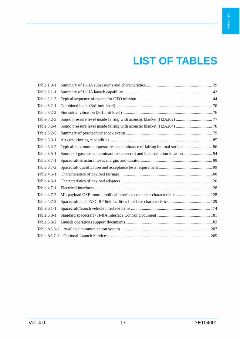
LIST OF TABLES
Table 1.3-1 Summary of H-IIA subsystems and characteristics .............................................................. 29
Table 2.1-1 Summary of H-IIA launch capability ................................................................................... 43
Table 2.1-2 Typical sequence of events for GTO mission ....................................................................... 44
Table 3.2-1 Combined loads (3σLimit level) .......................................................................................... 76
Table 3.2-2 Sinusoidal vibration (3σLimit level) .................................................................................... 76
Table 3.2-3 Sound pressure level inside fairing with acoustic blanket (H2A202) .................................. 77
Table 3.2-4 Sound pressure level inside fairing with acoustic blanket (H2A204) .................................. 78
Table 3.2-5 Summary of pyrotechnic shock events ................................................................................. 79
Table 3.3-1 Air conditioning capabilities ................................................................................................ 85
Table 3.3-2 Typical maximum temperatures and emittance of fairing internal surface .......................... 86
Table 3.5-1 Source of gaseous contaminant to spacecraft and its installation location ........................... 94
Table 3.7-1 Spacecraft structural tests, margin, and duration .................................................................. 99
Table 3.7-2 Spacecraft qualification and acceptance tests requirement .................................................. 99
Table 4.5-1 Characteristics of payload fairings ..................................................................................... 108
Table 4.6-1 Characteristics of payload adapters .................................................................................... 120
Table 4.7-1 Electrical interfaces ............................................................................................................ 128
Table 4.7-2 ML payload GSE room umbilical interface connector characteristics ............................... 128
Table 4.7-3 Spacecraft and TNSC RF link facilities Interface characteristics ...................................... 129
Table 6.1-1 Spacecraft/launch vehicle interface items .......................................................................... 174
Table 6.3-1 Standard spacecraft / H-IIA Interface Control Document .................................................. 181
Table 6.3-2 Launch operations support documents ............................................................................... 182
Table A3.6-1 Available communication system .................................................................................... 207
Table A3.7-1 Optional Launch Services ................................................................................................ 209
List of Tables

YET04001 18 Ver. 4.0
Ver. 4.0 19 YET04001
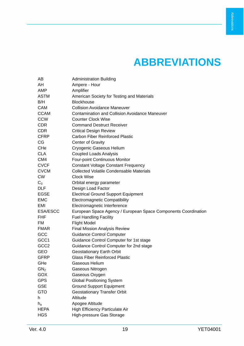
ABBREVIATIONS
AB Administration Building AH Ampere - Hour AMP Amplifier ASTM American Society for Testing and Materials B/H Blockhouse CAM Collision Avoidance Maneuver CCAM Contamination and Collision Avoidance Maneuver CCW Counter Clock Wise CDR Command Destruct Receiver CDR Critical Design Review CFRP Carbon Fiber Reinforced Plastic CG Center of Gravity CHe Cryogenic Gaseous Helium CLA Coupled Loads Analysis CM4 Four-point Continuous Monitor CVCF Constant Voltage Constant Frequency CVCM Collected Volatile Condensable Materials CW Clock Wise C3 Orbital energy parameter DLF Design Load Factor EGSE Electrical Ground Support Equipment EMC Electromagnetic Compatibility EMI Electromagnetic Interference ESA/ESCC European Space Agency / European Space Components Coordination FHF Fuel Handling Facility FM Flight Model FMAR Final Mission Analysis Review GCC Guidance Control Computer GCC1 Guidance Control Computer for 1st stage GCC2 Guidance Control Computer for 2nd stage GEO Geostationary Earth Orbit GFRP Glass Fiber Reinforced Plastic GHe Gaseous Helium GN2 Gaseous Nitrogen GOX Gaseous Oxygen GPS Global Positioning System GSE Ground Support Equipment GTO Geostationary Transfer Orbit h Altitude ha Apogee Altitude HEPA High Efficiency Particulate Air HGS High-pressure Gas Storage
Abbreviations
YET04001 20 Ver. 4.0
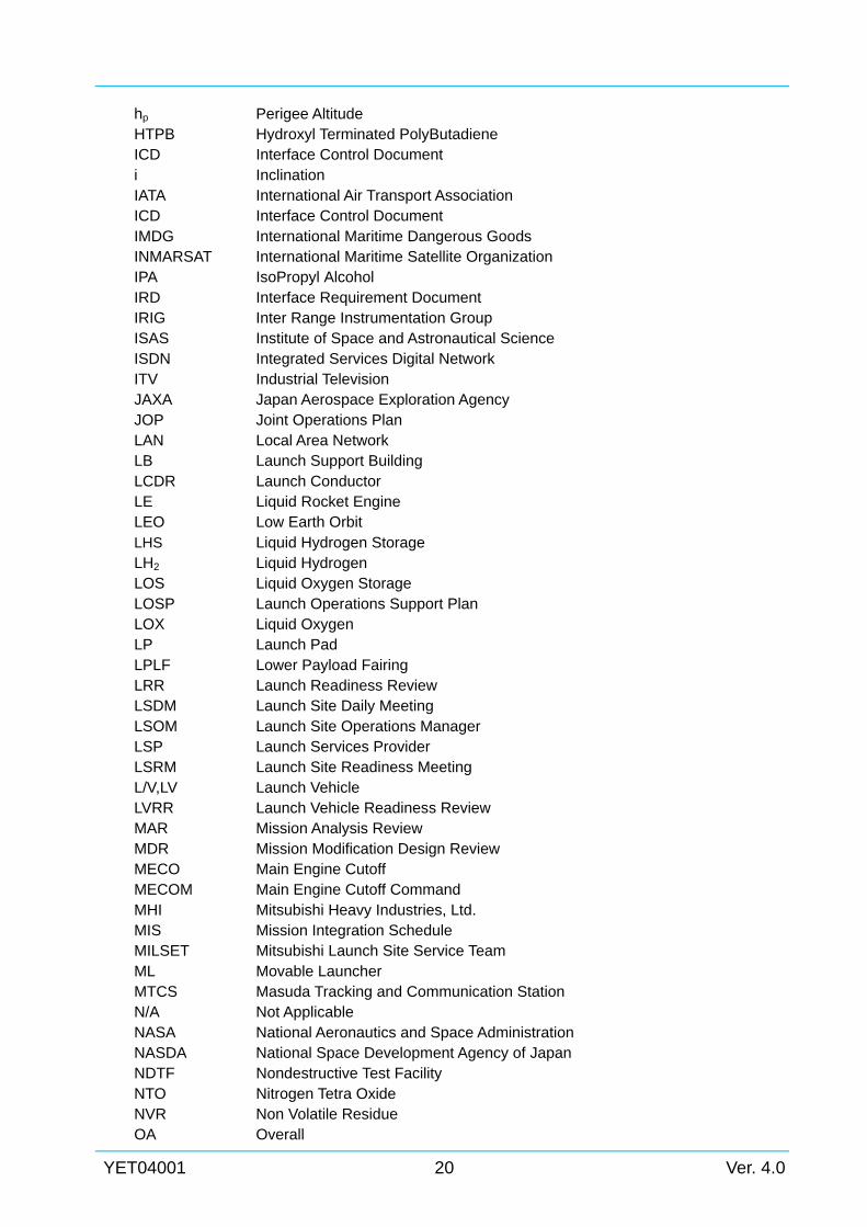
hp Perigee Altitude HTPB Hydroxyl Terminated PolyButadiene ICD Interface Control Document i Inclination IATA International Air Transport Association ICD Interface Control Document IMDG International Maritime Dangerous Goods INMARSAT International Maritime Satellite Organization IPA IsoPropyl Alcohol IRD Interface Requirement Document IRIG Inter Range Instrumentation Group ISAS Institute of Space and Astronautical Science ISDN Integrated Services Digital Network ITV Industrial Television JAXA Japan Aerospace Exploration Agency JOP Joint Operations Plan LAN Local Area Network LB Launch Support Building LCDR Launch Conductor LE Liquid Rocket Engine LEO Low Earth Orbit LHS Liquid Hydrogen Storage LH2 Liquid Hydrogen LOS Liquid Oxygen Storage LOSP Launch Operations Support Plan LOX Liquid Oxygen LP Launch Pad LPLF Lower Payload Fairing LRR Launch Readiness Review LSDM Launch Site Daily Meeting LSOM Launch Site Operations Manager LSP Launch Services Provider LSRM Launch Site Readiness Meeting L/V,LV Launch Vehicle LVRR Launch Vehicle Readiness Review MAR Mission Analysis Review MDR Mission Modification Design Review MECO Main Engine Cutoff MECOM Main Engine Cutoff Command MHI Mitsubishi Heavy Industries, Ltd. MIS Mission Integration Schedule MILSET Mitsubishi Launch Site Service Team ML Movable Launcher MTCS Masuda Tracking and Communication Station N/A Not Applicable NASA National Aeronautics and Space Administration NASDA National Space Development Agency of Japan NDTF Nondestructive Test Facility NTO Nitrogen Tetra Oxide NVR Non Volatile Residue OA Overall
Ver. 4.0 21 YET04001
OBS On Board Software OHF Oxidizer Handling Facility OIS Operational Intercommunication Telephone System OSO Osaki Staff Office PAF Payload Adapter Fitting PCD Pitch Circle Diameter PCS Probability Command Shutdown PDB2 Power Distribution Box 2nd Stage PDP Power Distribution Panel PFM Proto Flight Model PFM Post Flight Meeting PIF Poly Iso-cyanurate Form pl Place PLA Payload Adapter PLF Payload Fairing PMAR Preliminary Mission Analysis Review PMM Program Management Meeting PRD Program Requirement Document PRR Program Requirement Review PSR Pre-Shipment Review PSS Payload Support Structure PTFE Polytetrafluoroethylene Q Dynamic Pressure QD Quick Disconnect R Radius RCC Range Control Center RCS Reaction Control (gas jet) System REF Reference RF Radio Frequency RH Relative Humidity RNR Radio Navigation Receiver RSRR Range Safety Readiness Review SBB Solid Booster Test Building S/C,SC Spacecraft SCAPE Self-Contained Atmospheric Protective Ensemble SCO Spacecraft Organization (both customer and manufacturer) SCRR Spacecraft Readiness Review SDB2 Sequence Distribution Box 2nd Stage SECO Second Engine Cutoff SECOM Second Engine Cutoff Command SECT Section SEIG Second Engine Ignition SEP Separation SFA Spacecraft and Fairing Assembly Building SFA2 No.2 Spacecraft and Fairing Assembly Building SLB Supporting Launch Building Sm3 Standard Cubic Meter SOW Statement of Work SPL Sound Pressure Level SPLB Small Satellite Propellant Loading Building SPM Solid Propellant Motor
YET04001 22 Ver. 4.0
SPM Single Point Monitor SR Safety Review SRB Solid Rocket Booster SSO Sun Synchronous Orbit STA1 No.1 Spacecraft Test and Assembly Building STA2 No.2 Spacecraft Test and Assembly Building STA STAtion (station from reference plane) STM Structural Test Model T.B.C. To Be Confirmed T.B.D. To Be Determined T.B.R. To Be Revised TDRSS Tracking and Data Relay Satellite System TIM Technical Interchange Meeting TML Total Mass Loss TNSC Tanegashima Space Center TVC Thrust Vector Control TYP Typical UHF Ultra High Frequency UM Umbilical Mast UPLF Upper Payload Fairing UPS Uninterruptible Power System UTC Coordinated Universal Time VAB Vehicle Assembly Building VC+UV Visibly Clean Plus Ultra-Violet VDC Voltage Direct Current VOS Vehicle On Stand XLR X Latching Resilient Rubber Compound α Angle of Attack φ Diameter ω Argument of Perigee Ω Ascending Node
Chapter 1
Ver. 4.0 23 YET04001
Ch
apter 1
Chapter 1 INTRODUCTION
1.1 Purpose
This user's manual provides information on MHI Launch Services, H-IIA launch system, and
following associated information for potential customers to assess the suitability and
compatibility with the spacecraft.
(1) General description of H-IIA launch vehicle and launch site (Tanegashima Space Center,
TNSC)
(2) Mission performance
(3) Prelaunch and flight environmental conditions
(4) Interface with the spacecraft and H-IIA launch vehicle
(5) Launch operations
(6) Interface management process
1.2 MHI Launch services
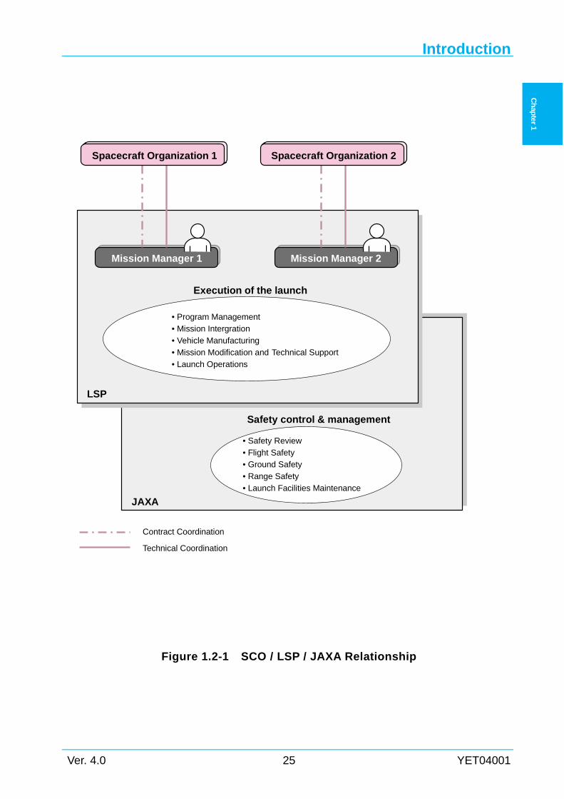
1.2.1 Description Japan Aerospace Exploration Agency (JAXA) developed the H-IIA launch system including
the launch vehicle and launch facilities to upgrade former H-II launch system. Mitsubishi Heavy
Industries (MHI) has acted as a launch services provider through technical transfer from JAXA
since April, 2003 and has started launch services business since 2007.
All services associated with spacecraft including interface coordination are provided by MHI
as well as launch vehicle manufacturing and launch operations at TNSC. Responsibility
associated with flight safety, range safety and launch site facility is taken by JAXA. For each
mission, MHI assigns a mission manager as a single point of contact to work with the customer
and coordinate contractual and technical interface activities for the whole mission. Figure 1.2-1
shows the organizational relationship of customer, JAXA, and MHI and major responsibilities of
the Mission Manager.
1.2.2 Definition (1) Spacecraft Organization(SCO)
SCO is defined as spacecraft owner and spacecraft manufacturer.
(2) Launch Services Provider(LSP)
The H-IIA launch vehicle services provider is Mitsubishi Heavy Industries, who will execute
Chapter 1
YET04001 24 Ver. 4.0
Ch
apter 1
spacecraft launch services with JAXA Tanegashima Space Center and other partner companies.
(3) Mitsubishi Launch Site Service Team (MILSET)
MILSET is a team organized to launch the H-IIA launch vehicle by LSP.
(4) Launch operations
Generic term referring to activities preformed in the launch site, such as assembly, preparation,
testing and joint operations of the spacecraft and launch vehicle.
(5) Spacecraft Program Manager
Spacecraft Program Manager is a SCO person who is responsible for all the interface activity
with LSP.
(6) Spacecraft Mission Director
Spacecraft Mission Director is a SCO person who is responsible for the launch activity
coordination.
(7) Mission Manager
Mission Manager is an LSP person who is responsible for contracts, interface coordination of
the launch, and technical matters related to launch operations (from spacecraft arrival at TNSC
through completion of the post liftoff operations).
(8) Spacecraft system
Spacecraft system is a system including the spacecraft, associated facilities, and Ground
Support Equipment (GSE).
(9) H-IIA launch vehicle system
H-IIA launch vehicle system is a system including the launch vehicle, associated facilities,
and GSE.
(10) “L”
“L” is defined as launch day. For example, “L- (number)” represents month(s) or day(s) up to
the launch day.
(11) “X”
“X” is defined as launch time. For example, “X- (number)” represents hour(s), minute(s), or
second(s) up to lift off.
Introduction
Ver. 4.0 25 YET04001
Ch
apter 1
Figure 1.2-1 SCO / LSP / JAXA Relationship
JAXA
Mission Manager 1
Spacecraft Organization 1
Mission Manager 2
Spacecraft Organization 2
• Program Management
• Mission Intergration
• Vehicle Manufacturing
• Mission Modification and Technical Support
• Launch Operations
• Safety Review
• Flight Safety• Ground Safety
• Range Safety
• Launch Facilities Maintenance
LSP
Contract Coordination
Technical Coordination
Execution of the launch
Safety control & management
Chapter 1
YET04001 26 Ver. 4.0
Ch
apter 1
1.3 H-IIA Launch System
1.3.1 H-IIA Launch Vehicle Description
(1) General
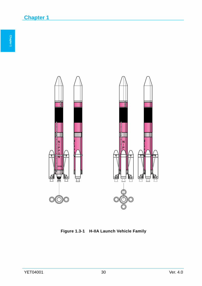
Figure 1.3-1 shows H-IIA launch vehicle family, and Table 1.3-1 shows a summary of H-IIA
subsystems and characteristics.
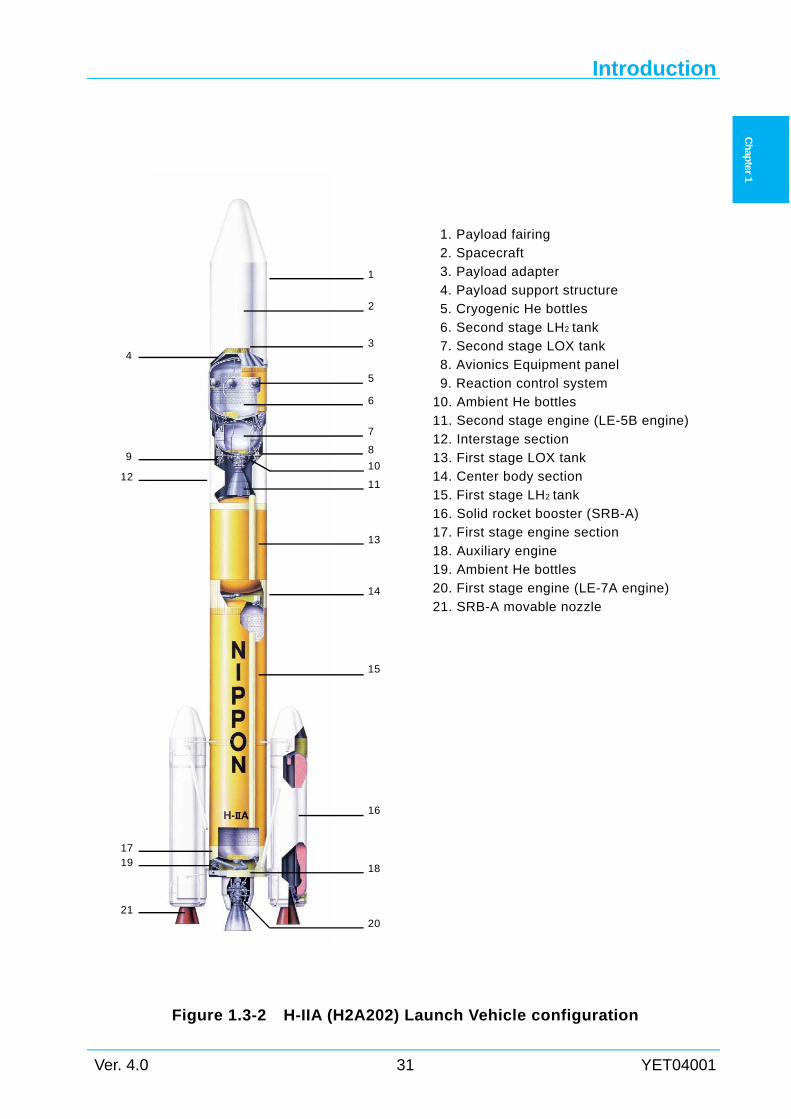
The "H2A202" consists of the first stage with two SRB-As, the second stage, and the payload
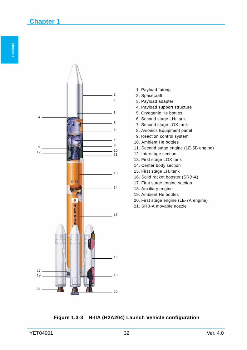
fairing as shown in Figure 1.3-2. The "H2A204" consists of the first stage with four SRB-As, the
second stage, and the payload fairing as shown in Figure 1.3-3.
An optional long-coast GTO (KOHDO-KA) is available for customers to effectively minimize
the spacecraft onboard propellant needed to reach GEO from GTO and provide an additional
lifetime. Overview of the long-coast GTO option is described later in this section 1.3.1 (7).
(2) First Stage
The first stage consists of the high performance cryogenic LE-7A engine, engine section, LH2
tank, center body section, LOX tank and interstage section. The LE-7A engine produces 1100kN
of thrust using liquid hydrogen (LH2) and liquid oxygen (LOX) as propellant. Two or four solid
rocket boosters (SRB-A) are attached to the first stage in order to augment the total thrust during
ascent phase.
(3) SRB-A (Solid Rocket Booster)
SRB-As augment total thrust by firing for approximately 100 seconds from liftoff for the
H2A202, and 120 seconds for the H2A204. The motor case of the SRB-A is monolithic and
made of filament winding composite material (CFRP). Additionally, electromechanical thrust
vector control (TVC) system for gimbaling the nozzle is applied.
(4) Second Stage
The second stage consists of the highly reliable cryogenic LE-5B engine, LH2 tank, LOX tank
and avionics system installed on the equipment panel. The LE-5B engine, which produces
137kN of thrust using liquid hydrogen (LH2) and liquid oxygen (LOX) as propellant, has a
multi-restart capability to meet various mission requirements. Attitude control is performed
using reliable electromechanical actuators of the LE-5B engine and the hydrazine gas-jet
reaction control system (RCS).
The RCS is used for attitude control and propellant settling of the second stage before and
after the spacecraft separation. The RCS is mounted under the avionics equipment panel.
Most components of the avionics system are mounted on the avionics equipment panel.
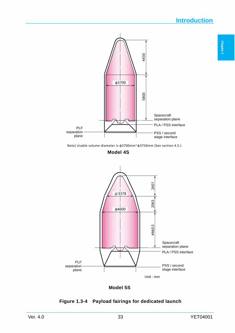
(5) Payload fairings
The payload fairing protects the spacecraft from external environment to which the spacecraft
is exposed, from the time of encapsulation through the atmospheric ascent phase.
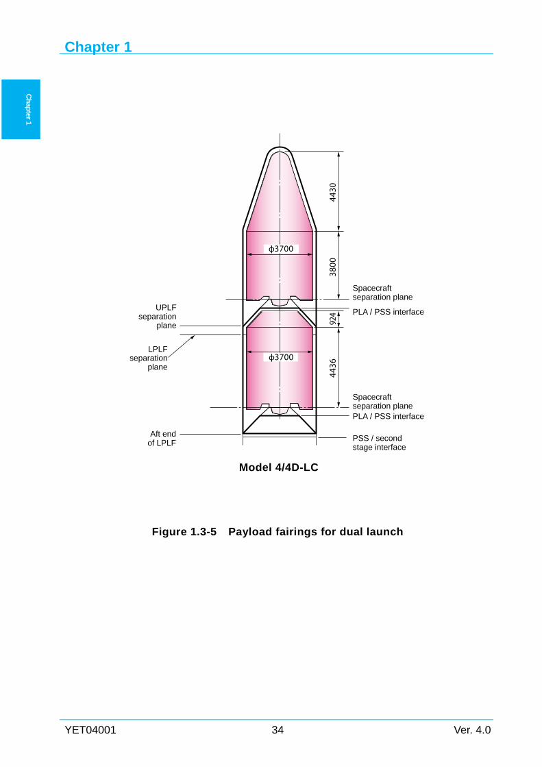
3 types of payload fairings shown in Figure 1.3-4 and Figure 1.3-5 are available. Each type is
compatible with H-IIA launch vehicle family.
Allowable envelop of the spacecraft in the fairing is shown in Figure 1.3-4 for the Model 4S
Introduction
Ver. 4.0 27 YET04001
Ch
apter 1
and 5S used for a dedicated launch, and Figure 1.3-5 for the Model 4/4D-LC used for dual
launch.
Further description of payload fairings is provided in Chap. 4 and Appendix 4.
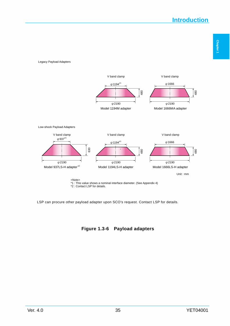
(6) Payload adapters / separation system
The spacecraft is mounted on the launch vehicle using a payload adapter shown in Figure
1.3-6.
Several types of payload adapters are available. Each type is compatible with H-IIA launch
vehicle family, including separation systems.
Figure 1.3-6 shows the payload adapters with dimensions available to the customer. Detail
information on the adapters and separation systems including mechanical interfaces are
presented in Chap. 4 and Appendix 4.
(7) Option for long-coast GTO mission
For geostationary orbit mission, long-coast second stage option is available to reduce the
delta-V, which the spacecraft is injected into geostationary orbit from the geostationary transfer
orbit (GTO), by boosting the second stage near the apogee.
Following modifications applied to the second stage make it possible to enhance the mission
time, and suppress the cryogenic propellant loss during long-coast.
The standard GTO mission time is approximately 0.5h, while the long-coast GTO mission is
approximately 4.5h.
(a) White painted LH2 tank
(b) Additional LOX trickling chill down subsystem
(c) Additional GH2 vent subsystem
(d) LE-5B 60% throttling capability
(e) Additional battery
(f) Miscellaneous improvement for long-time coast mission
Associated information is presented in the following sections.
2.1.1 Mission profile
2.3 Geostationary Transfer Orbit (GTO) Mission
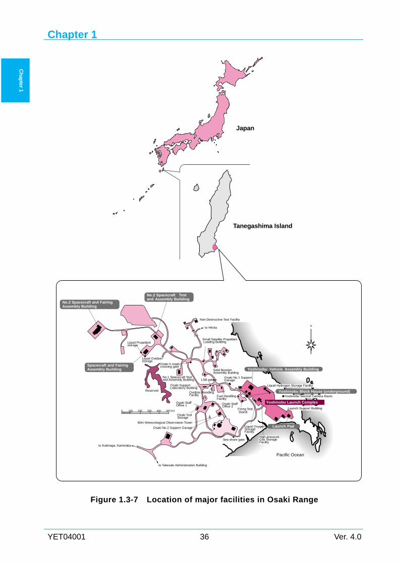
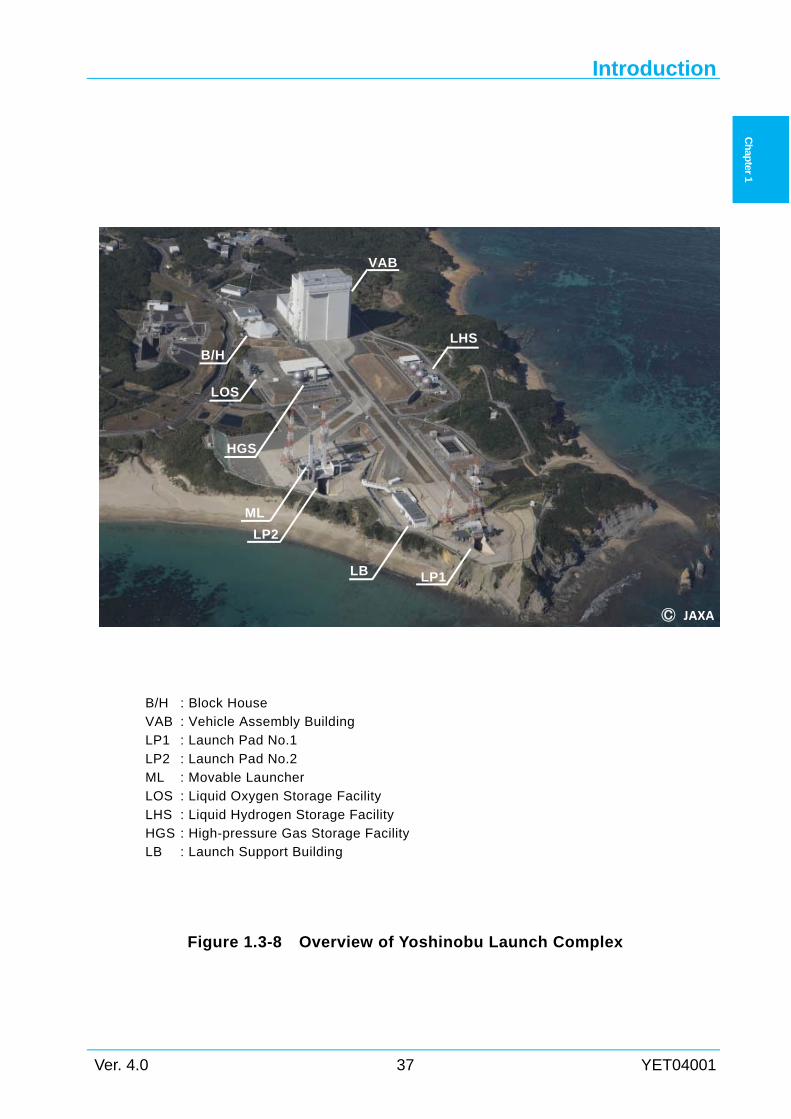
1.3.2 Launch Facilities
The H-IIA launch vehicle is finally integrated and launched from the TNSC in Tanegashima
Island, located at the southwest of Japan.
Launch operations are carried out in Osaki Range of the TNSC. Figure 1.3-7 and Figure 1.3-8
shows the location of the TNSC and its major facilities, and the overview of the launch complex,
respectively.
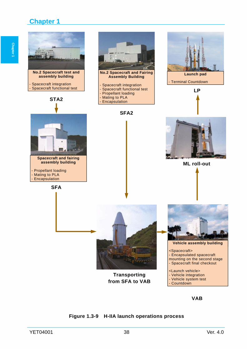
Figure 1.3-9 shows the typical launch site operations process. Customer is offered to use the
buildings for spacecraft processing as either of the following cases.
Chapter 1
YET04001 28 Ver. 4.0
Ch
apter 1
Case 1: (Normal)
-For spacecraft checkout, No.2 Spacecraft Test and Assembly Building (STA2)
-For propellant loading and encapsulation, Spacecraft and Fairing Assembly Building
(SFA)
Case 2: (Option)
-For spacecraft checkout propellant loading and encapsulation, No.2 Spacecraft and
Fairing Assembly Building (SFA2)
Case3: (Backup)
-For spacecraft checkout, No.1 Spacecraft Test and Assembly Building (STA1)
-For propellant loading, Small Satellite Propellant Loading Building (SPLB)
-For encapsulation, Spacecraft and Fairing Assembly Building (SFA)
Introduction
Ver. 4.0 29 YET04001
Ch
apter 1
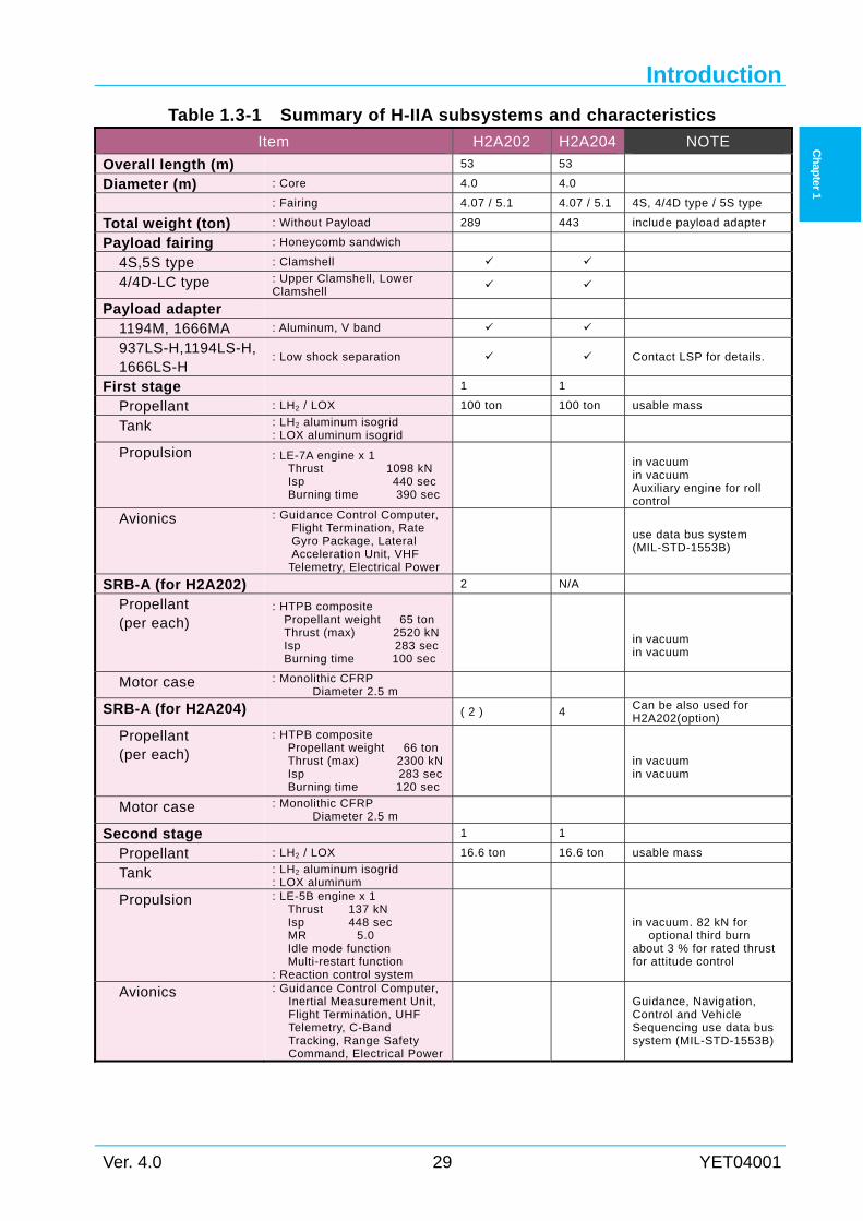
Table 1.3-1 Summary of H-IIA subsystems and characteristics
Item H2A202 H2A204 NOTE
Overall length (m) 53 53
Diameter (m) : Core 4.0 4.0
: Fairing 4.07 / 5.1 4.07 / 5.1 4S, 4/4D type / 5S type
Total weight (ton) : Without Payload 289 443 include payload adapter
Payload fairing : Honeycomb sandwich
4S,5S type : Clamshell
4/4D-LC type : Upper Clamshell, Lower Clamshell
Payload adapter
1194M, 1666MA : Aluminum, V band
937LS-H,1194LS-H,1666LS-H
: Low shock separation Contact LSP for details.
First stage 1 1
Propellant : LH2 / LOX 100 ton 100 ton usable mass
Tank : LH2 aluminum isogrid : LOX aluminum isogrid
Propulsion : LE-7A engine x 1 Thrust 1098 kN Isp 440 sec Burning time 390 sec
in vacuum in vacuum Auxiliary engine for roll control
Avionics : Guidance Control Computer, Flight Termination, Rate Gyro Package, Lateral Acceleration Unit, VHF
Telemetry, Electrical Power
use data bus system (MIL-STD-1553B)
SRB-A (for H2A202) 2 N/A
Propellant (per each)
: HTPB composite Propellant weight 65 ton Thrust (max) 2520 kNIsp 283 sec Burning time 100 sec
in vacuum in vacuum
Motor case : Monolithic CFRP Diameter 2.5 m
SRB-A (for H2A204) ( 2 ) 4 Can be also used for H2A202(option)
Propellant (per each)
: HTPB composite Propellant weight 66 ton Thrust (max) 2300 kNIsp 283 secBurning time 120 sec
in vacuum in vacuum
Motor case : Monolithic CFRP Diameter 2.5 m
Second stage 1 1
Propellant : LH2 / LOX 16.6 ton 16.6 ton usable mass
Tank : LH2 aluminum isogrid : LOX aluminum
Propulsion : LE-5B engine x 1 Thrust 137 kN Isp 448 sec MR 5.0 Idle mode function Multi-restart function
: Reaction control system
in vacuum. 82 kN for
optional third burn about 3 % for rated thrust for attitude control
Avionics : Guidance Control Computer, Inertial Measurement Unit, Flight Termination, UHF Telemetry, C-Band Tracking, Range Safety Command, Electrical Power
Guidance, Navigation, Control and Vehicle Sequencing use data bus system (MIL-STD-1553B)
Chapter 1
YET04001 30 Ver. 4.0
Ch
apter 1
Figure 1.3-1 H-IIA Launch Vehicle Family
Introduction
Ver. 4.0 31 YET04001
Ch
apter 1
Figure 1.3-2 H-IIA (H2A202) Launch Vehicle configuration
1. Payload fairing 2. Spacecraft
3. Payload adapter 4. Payload support structure 5. Cryogenic He bottles
6. Second stage LH2 tank 7. Second stage LOX tank 8. Avionics Equipment panel
9. Reaction control system 10. Ambient He bottles 11. Second stage engine (LE-5B engine)
12. Interstage section 13. First stage LOX tank 14. Center body section
15. First stage LH2 tank 16. Solid rocket booster (SRB-A) 17. First stage engine section
18. Auxiliary engine 19. Ambient He bottles 20. First stage engine (LE-7A engine)
21. SRB-A movable nozzle
1
6
5
4 3
2
10
8
7
16
15
14
13
1112
9
21
19 17
20
18
Chapter 1
YET04001 32 Ver. 4.0
Ch
apter 1
Figure 1.3-3 H-IIA (H2A204) Launch Vehicle configuration
1. Payload fairing
2. Spacecraft 3. Payload adapter 4. Payload support structure
5. Cryogenic He bottles 6. Second stage LH2 tank 7. Second stage LOX tank
8. Avionics Equipment panel 9. Reaction control system
10. Ambient He bottles
11. Second stage engine (LE-5B engine) 12. Interstage section 13. First stage LOX tank
14. Center body section 15. First stage LH2 tank 16. Solid rocket booster (SRB-A)
17. First stage engine section 18. Auxiliary engine 19. Ambient He bottles
20. First stage engine (LE-7A engine) 21. SRB-A movable nozzle
1
6
5
4 3
2
10
8
7
15
14
13
1112
9
16
21
19 17
20
18
Introduction
Ver. 4.0 33 YET04001
Ch
apter 1
Note) Usable volume diameter is φ3700mm~φ3750mm (See section 4.5.)
Model 4S
Model 5S
Figure 1.3-4 Payload fairings for dedicated launch
Unit : mm
Spacecraftseparation plane
PLA / PSS interface
PSS / secondstage interface
2601
2063
4460
.5
PLFseparation
plane
φ4600
φ3378
5800
Spacecraftseparation plane
PLA / PSS interface
PSS / secondstage interface
PLFseparation
plane
4430
φ3700
Chapter 1
YET04001 34 Ver. 4.0
Ch
apter 1
Model 4/4D-LC
Figure 1.3-5 Payload fairings for dual launch
3800
4430
4436
924
Spacecraftseparation planePLA / PSS interface
UPLFseparation
plane
Aft endof LPLF
Spacecraftseparation plane
PLA / PSS interface
LPLFseparation
plane
φ3700
φ3700
PSS / secondstage interface
Introduction
Ver. 4.0 35 YET04001
Ch
apter 1
LSP can procure other payload adapter upon SCO’s request. Contact LSP for details.
Figure 1.3-6 Payload adapters
Unit : mm
Low-shock Payload Adapters
Model 1666LS-H adapter
V band clamp
φ1666
φ2190
480
480
Model 1194LS-H adapter
V band clamp
φ1194*1
φ2190
Model 937LS-H adapter*2
φ2190
630
V band clamp
φ937*1
<Note>*1 : This value shows a nominal interface diameter. (See Appendix 4)*2 : Contact LSP for details.
Legacy Payload Adapters
Model 1666MA adapter
V band clamp
φ1666
φ2190
480
480
Model 1194M adapter
V band clamp
φ1194*1
φ2190
Chapter 1
YET04001 36 Ver. 4.0
Ch
apter 1
Figure 1.3-7 Location of major facilities in Osaki Range
Liquid Hydrogen Storage Facility
Liquid Propellantstorage
Liquid Oxidizerstorage
Spacecraft and FairingAssembly Building
No.2 Spacecraft and FairingAssembly Building
No.2 Spacecraft Testand Assembly Building
Small Satellite Propellant Loading Building
Solid BoosterAssembly Building
to Hirota
Yoshinobu Launch Complex
Non-Destructive Test Facility
LSB gateOsaki No.1 SupportGarage
Osaki 5 roadscrossing gate
Yoshinobu Vehicle Assembly Building
Yoshinobu Block House (underground)Oxidizer HandlingFacility
Osaki StaffOffice 2
Sea shore gate
Liquid OxygenStorageFacility
High-pressureGas StorageFacility
Firing Test Stand
Launch Support Building
Yoshinobu Second Camera Room
No.1 Spacecraft Testand Assembly Building
Osaki SupportLaboratory Building
Osaki StaffOffice 1
Osaki ToolStorage
80m Meteorological Observation Tower
Pacific Ocean
Reservoir
to Kukinaga, Kaminaka
0 100 200 300 400 500 [m]
to Takesaki Administration Building
N
Launch Pad
Fuel HandlingFacility
Japan
Tanegashima Island
Osaki No.2 Support Garage
Introduction
Ver. 4.0 37 YET04001
Ch
apter 1
Figure 1.3-8 Overview of Yoshinobu Launch Complex
JAXA
B/H : Block House VAB : Vehicle Assembly Building LP1 : Launch Pad No.1
LP2 : Launch Pad No.2 ML : Movable Launcher LOS : Liquid Oxygen Storage Facility
LHS : Liquid Hydrogen Storage Facility HGS : High-pressure Gas Storage Facility LB : Launch Support Building
B/H
HGS
VAB
LHS
LP1
ML
LP2
LOS
LB
Chapter 1
YET04001 38 Ver. 4.0
Ch
apter 1
Figure 1.3-9 H-IIA launch operations process
No.2 Spacecraft test and assembly building
- Spacecraft integration - Spacecraft functional test
STA2
No.2 Spacecraft and Fairing Assembly Building
- Spacecraft integration - Spacecraft functional test - Propellant loading - Mating to PLA - Encapsulation
SFA
SFA2
Vehicle assembly building
<Spacecraft> - Encapsulated spacecraft mounting on the second stage - Spacecraft final checkout
<Launch vehicle> - Vehicle integration - Vehicle system test - Countdown
VAB
Launch pad
- Terminal Countdown
LP
ML roll-out Spacecraft and fairing
assembly building - Propellant loading - Mating to PLA - Encapsulation
Transporting from SFA to VAB
Introduction
Ver. 4.0 39 YET04001
Ch
apter 1
1.4 H-IIA Launch System Related Document
In addition to this user's manual, following two documents are available for the customer.
(1) Facility Guide for H-IIA Payload Launch Campaign
(2) Launch Vehicle Payload Safety Standard
These documents provide the customer with detailed information on launch facilities and
range safety requirements as a reference for the preliminary planning phase.
1.4.1 Facility Guide for H-IIA Payload Launch Campaign Buildings and associated facilities in TNSC and a description of the spacecraft launch site
operations are presented in this facility guide.
1.4.2 Launch Vehicle Payload Safety Standard
The requirements for safety control, spacecraft safety design, and launch site operations at
TNSC are described. In this user's manual, outline of safety requirements and description of
safety reviews is presented in section 6.4.
Chapter 1
YET04001 40 Ver. 4.0
Ch
apter 1
Intentionally blank
Chapter 2
Ver. 4.0 41 YET04001
Ch
apter 2
Chapter 2 PERFORMANCE
2.1 General This chapter describes the performance of the H-IIA launch vehicle. The H-IIA launch vehicle
accommodates a various mission using 2nd stage restart capabilities to meet SCO's requirements.
In this manual, following mission profiles are presented for preliminary planning purpose:
(1) Geostationary transfer orbit (GTO) mission
(2) Sun synchronous orbit (SSO) mission
(3) Low earth orbit (LEO) mission
(4) Earth escape mission
Typical launch capabilities of the H-IIA launch vehicle family is shown in Table 2.1-1. The
performance data in this chapter are based on standard mission modifications of payload fairing
described in Section 4.5. Depending on the final configurations and mission requirements of
SCO, actual launch capability will vary. Regarding detailed launch capabilities, please contact
LSP.
2.1.1 Mission profile This section describes typical mission profile and sequences of GTO mission for example.
Typical GTO mission profiles are shown in Figure 2.1-1 and Figure 2.1-2. Typical sequence of
events for standard GTO mission and long-coast GTO mission are shown in Table 2.1-2. For
other missions such as SSO and LEO, the time for each sequence of events and flight trajectories
will vary.
In the following paragraphs, time for sequence of events for H2A202 is representatively used
corresponding to Figure2.1-1.
2.1.1.1 Boost and first stage phase The main engine LE-7A is ignited at approximately 4.7 seconds before liftoff (X-0). After
detecting the rise of the LE-7A combustion pressure, two SRB-As are ignited (at approximately
0.5 second before X-0), subsequently the H-IIA launch vehicle lifts off from the Movable
Launcher (ML) , that is X-0. The SRB-As burn out at approximately 99 seconds after liftoff
(hereafter called X+99), and then separated from the core stage.
The payload fairing (PLF) is separated after a free molecular heat flux becomes less than 1135
W/m2, resulting the separation timing of the PLF being different in each mission. At
approximately X+396, the first stage engine (LE-7A) shutdown occurs. After LE-7A thrust has
Chapter 2
YET04001 42 Ver. 4.0
Ch
apter 2
tailed off, the first stage separation is executed.
The attitude control is conducted by the first stage engine gimbaling, the SRB-A nozzles
gimbaling, and auxiliary thrusters. The gimbaling of the first stage engine (LE-7A) contributes to
the pitch / yaw control throughout the booster and the first stage phase. The SRB-A engine
nozzle is gimbaled for the pitch / yaw / roll control. Roll axis control is executed by two
auxiliary thrusters after the SRB-As burn out.
2.1.1.2 Second stage phase After the first stage is separated, the second stage engine (LE-5B) is ignited (SEIG1). The
LE-5B engine burns for approximately 340 seconds. Just after the second stage (including the
payload) is injected to the parking orbit, the engine shuts down once (SECO1). During engine
burning, the pitch/yaw control is conducted by the gimbaling of the LE-5B and the roll control is
conducted by the reaction control system (RCS). After the engine cutoff, the vehicle starts the
coasting flight.
During the coast phase, preparations for the second stage engine restart take place. These are
propellant settling, pressure control of LOX / LH2 tanks, engine chilling down, attitude
maneuver and so on. In this phase, the attitude control of the pitch/yaw/roll is performed only by
the RCS.
Approximately X+1460 seconds, the LE-5B is restarted (SEIG2) and when the second stage
reaches the planned transfer orbit, the engine cutoff occurs again (SECO2). The second burning
duration is approximately 200 seconds in a standard GTO mission. Mission time of standard
GTO is approximately 0.5 hours.
After spacecraft / second stage separation, the contamination and collision avoidance
maneuver (CCAM) is conducted using the RCS and the residual propellant ejection.
In case of long-coast GTO mission, the second stage conducts over 10,000 sec coast after
SECO2, and then the LE-5B makes the third burn in order to increase the perigee altitude, and to
reduce the inclination, as shown in Table 2.1-2. Mission time of long-coast GTO is
approximately 4.5 hours.
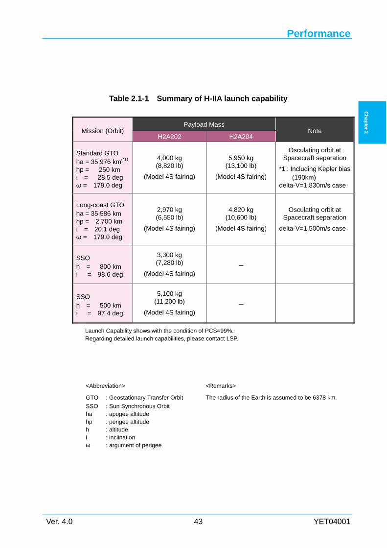
Performance
Ver. 4.0 43 YET04001
Ch
apter 2
Table 2.1-1 Summary of H-IIA launch capability
Launch Capability shows with the condition of PCS=99%. Regarding detailed launch capabilities, please contact LSP.
Mission (Orbit) Payload Mass
Note H2A202 H2A204
Standard GTO ha = 35,976 km(*1)
hp = 250 km i = 28.5 deg ω = 179.0 deg
4,000 kg (8,820 lb)
(Model 4S fairing)
5,950 kg (13,100 lb)
(Model 4S fairing)
Osculating orbit at Spacecraft separation
*1 : Including Kepler bias(190km)
delta-V=1,830m/s case
Long-coast GTO ha = 35,586 km
hp = 2,700 km i = 20.1 deg ω = 179.0 deg
2,970 kg (6,550 lb)
(Model 4S fairing)
4,820 kg (10,600 lb)
(Model 4S fairing)
Osculating orbit at Spacecraft separation
delta-V=1,500m/s case
SSO h = 800 km
i = 98.6 deg
3,300 kg (7,280 lb)
(Model 4S fairing) -
SSO h = 500 km
i = 97.4 deg
5,100 kg (11,200 lb)
(Model 4S fairing) -
<Abbreviation> <Remarks>
GTO
SSO ha hp h i ω
: Geostationary Transfer Orbit
: Sun Synchronous Orbit : apogee altitude : perigee altitude : altitude : inclination : argument of perigee
The radius of the Earth is assumed to be 6378 km.
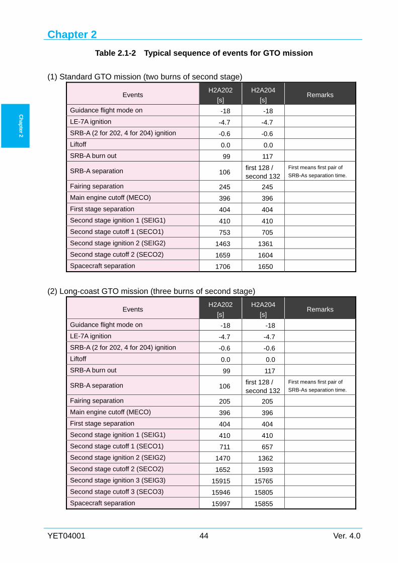
Chapter 2
YET04001 44 Ver. 4.0
Ch
apter 2
Table 2.1-2 Typical sequence of events for GTO mission
(1) Standard GTO mission (two burns of second stage)
Events H2A202
[s]
H2A204
[s] Remarks
Guidance flight mode on -18 -18
LE-7A ignition -4.7 -4.7
SRB-A (2 for 202, 4 for 204) ignition -0.6 -0.6
Liftoff 0.0 0.0
SRB-A burn out 99 117
SRB-A separation 106 first 128 / second 132
First means first pair of
SRB-As separation time.
Fairing separation 245 245
Main engine cutoff (MECO) 396 396
First stage separation 404 404
Second stage ignition 1 (SEIG1) 410 410
Second stage cutoff 1 (SECO1) 753 705
Second stage ignition 2 (SEIG2) 1463 1361
Second stage cutoff 2 (SECO2) 1659 1604
Spacecraft separation 1706 1650
(2) Long-coast GTO mission (three burns of second stage)
Events H2A202
[s]
H2A204
[s] Remarks
Guidance flight mode on -18 -18
LE-7A ignition -4.7 -4.7
SRB-A (2 for 202, 4 for 204) ignition -0.6 -0.6
Liftoff 0.0 0.0
SRB-A burn out 99 117
SRB-A separation 106 first 128 / second 132
First means first pair of
SRB-As separation time.
Fairing separation 205 205
Main engine cutoff (MECO) 396 396
First stage separation 404 404
Second stage ignition 1 (SEIG1) 410 410
Second stage cutoff 1 (SECO1) 711 657
Second stage ignition 2 (SEIG2) 1470 1362
Second stage cutoff 2 (SECO2) 1652 1593
Second stage ignition 3 (SEIG3) 15915 15765
Second stage cutoff 3 (SECO3) 15946 15805
Spacecraft separation 15997 15855
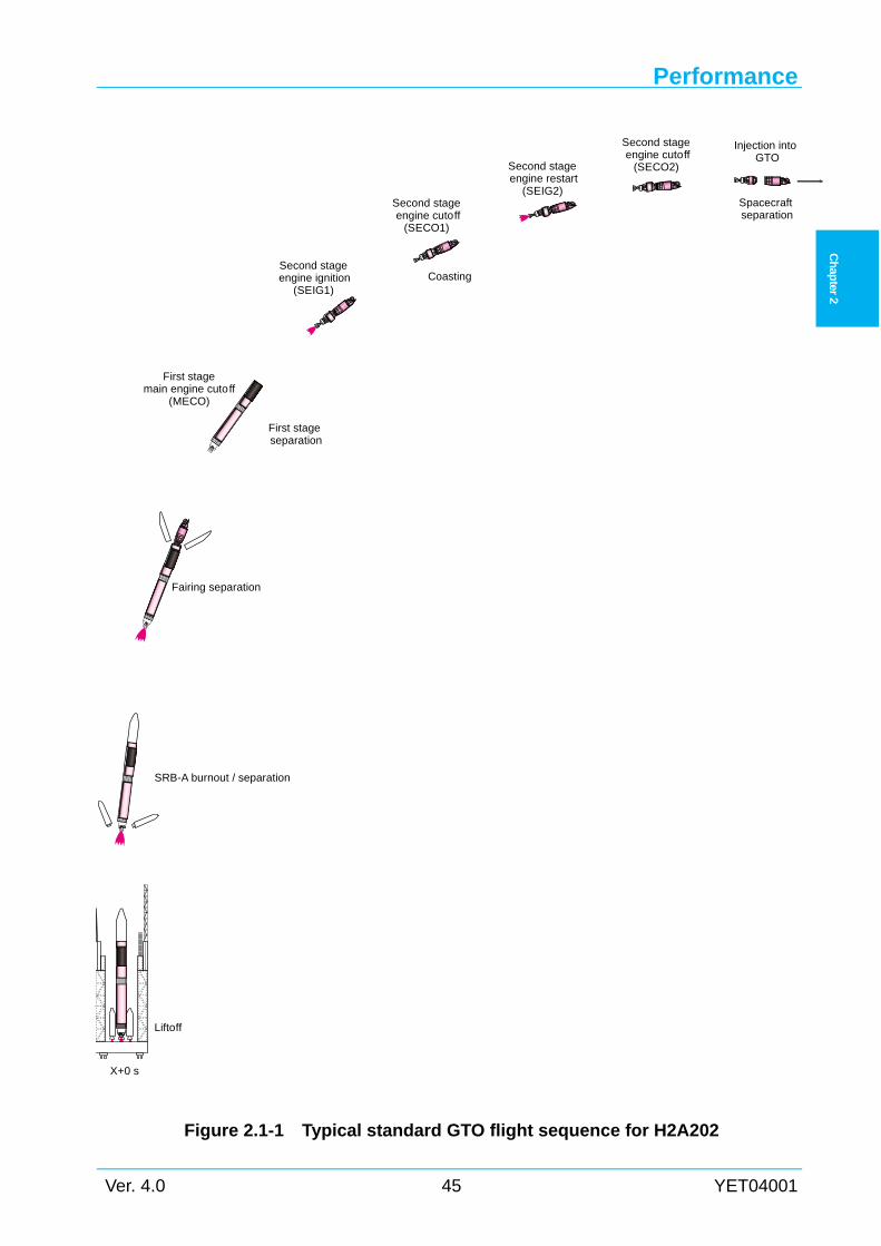
Performance
Ver. 4.0 45 YET04001
Ch
apter 2
Figure 2.1-1 Typical standard GTO flight sequence for H2A202
Liftoff
Second stage engine cutoff
(SECO1)
Second stage engine restart
(SEIG2)
Second stage engine cutoff
(SECO2)
Injection intoGTO
Spacecraft separation
Coasting
Fairing separation
First stageseparation
Second stage engine ignition
(SEIG1)
First stagemain engine cutoff
(MECO)
SRB-A burnout / separation
X+0 s
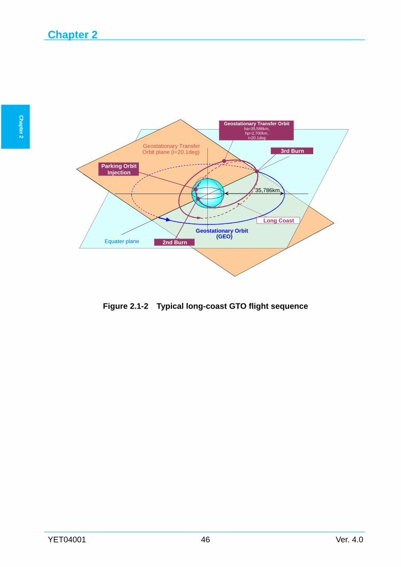
Chapter 2
YET04001 46 Ver. 4.0
Ch
apter 2
Figure 2.1-2 Typical long-coast GTO flight sequence
Equater plane
Geostationary Orbit(GEO)
Geostationary TransferOrbit plane (i=20.1deg)
Long Coast
3rd Burn
2nd Burn
Parking OrbitInjection
Geostationary Transfer Orbitha=35,586km,hp=2,700km,
i=20.1deg
35,786km
Performance
Ver. 4.0 47 YET04001
Ch
apter 2
2.2 Launch performance definition
2.2.1 Payload mass Payload mass is referred to as launch capability in this manual. Payload mass is defined as the
total mass of the spacecraft injected into the target orbit. PLA is a part of H-IIA, therefore
“Payload Mass” does not include PLA mass.
2.2.2 Launch vehicle configurations Unless otherwise noted, model 4S fairing is used for H-IIA performance presented in this
manual. Other types of fairings are also available, such as model 5S or 4/4D-LC for dual-launch
or greater volume than model 4S fairing. However, performance will degrade due to the
difference of fairing mass and aerodynamic drag as follows:
< Model 5S fairing >
Approximately 0.3 metric-tons less than the performance with model 4S fairing.
< Model 4/4D-LC fairing >
The sum of two satellites should be approximately 1.1 metric-tons less than the performance
with model 4S fairing. For example, if the performance with model 4S fairing is 5.1 metric-ton,
two satellites weighting 2.0 metric-tons each can be injected into the same orbit.
2.2.3 Launch vehicle performance The H-IIA launch vehicle performance is presented with 99% probability of second stage
command shut down.
Chapter 2
YET04001 48 Ver. 4.0
Ch
apter 2
2.3 Geostationary Transfer Orbit (GTO) Mission
2.3.1 Launch capability for dedicated launch (1) Standard GTO mission
Payload mass for standard GTO dedicated-launch mission based on typical orbital parameters
in Section 2.3.3(1) are as follows.
For H2A202 (delta-V to GEO =1830m/s),
-Model 4S fairing: 4,000 kg
-Model 5S fairing: 3,700 kg
For H2A204 (delta-V to GEO =1830m/s),
-Model 4S fairing: 5,950 kg
-Model 5S fairing: 5,700 kg
Payload mass based on other orbit parameters are shown as below.
-H2A202 and H2A204 with model 4S fairing: Figure 2.3-1
-H2A202 and H2A204 with model 5S fairing: Figure 2.3-2
(2) Long-coast GTO mission
Payload mass for long-coast GTO dedicated-launch mission based on typical orbital
parameters in Section 2.3.3(2) are as follows.
For H2A202 (delta-V to GEO =1500m/s),
-Model 4S fairing: 2,970 kg
-Model 5S fairing: 2,670 kg
For H2A204 (delta-V to GEO =1500m/s),
-Model 4S fairing: 4,820 kg
-Model 5S fairing: 4,520 kg
Payload mass based on other orbit parameters are shown as below.
-H2A202 with model 4S fairing: Figure 2.3-3
-H2A202 with model 5S fairing: Figure 2.3-4
-H2A204 with model 4S fairing: Figure 2.3-5
-H2A204 with model 5S fairing: Figure 2.3-6
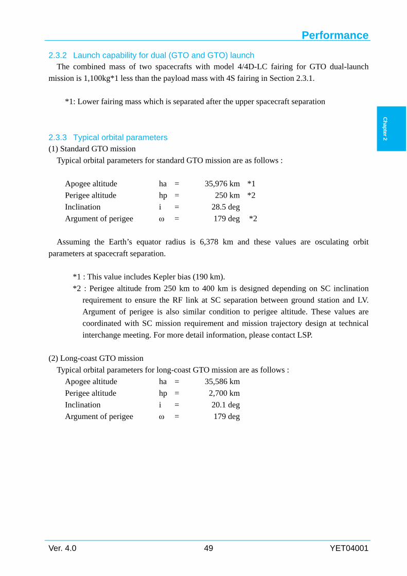
Performance
Ver. 4.0 49 YET04001
Ch
apter 2
2.3.2 Launch capability for dual (GTO and GTO) launch The combined mass of two spacecrafts with model 4/4D-LC fairing for GTO dual-launch
mission is 1,100kg*1 less than the payload mass with 4S fairing in Section 2.3.1.
*1: Lower fairing mass which is separated after the upper spacecraft separation
2.3.3 Typical orbital parameters (1) Standard GTO mission
Typical orbital parameters for standard GTO mission are as follows :
Apogee altitude ha = 35,976 km *1
Perigee altitude hp = 250 km *2
Inclination i = 28.5 deg
Argument of perigee ω = 179 deg *2
Assuming the Earth’s equator radius is 6,378 km and these values are osculating orbit
parameters at spacecraft separation.
*1 : This value includes Kepler bias (190 km).
*2 : Perigee altitude from 250 km to 400 km is designed depending on SC inclination
requirement to ensure the RF link at SC separation between ground station and LV.
Argument of perigee is also similar condition to perigee altitude. These values are
coordinated with SC mission requirement and mission trajectory design at technical
interchange meeting. For more detail information, please contact LSP.
(2) Long-coast GTO mission
Typical orbital parameters for long-coast GTO mission are as follows :
Apogee altitude ha = 35,586 km
Perigee altitude hp = 2,700 km
Inclination i = 20.1 deg
Argument of perigee ω = 179 deg
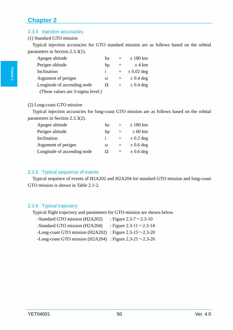
Chapter 2
YET04001 50 Ver. 4.0
Ch
apter 2
2.3.4 Injection accuracies (1) Standard GTO mission
Typical injection accuracies for GTO standard mission are as follows based on the orbital
parameters in Section 2.3.3(1).
Apogee altitude ha = ± 180 km
Perigee altitude hp = ± 4 km
Inclination i = ± 0.02 deg
Argument of perigee ω = ± 0.4 deg
Longitude of ascending node Ω = ± 0.4 deg
(These values are 3-sigma level.)
(2) Long-coast GTO mission
Typical injection accuracies for long-coast GTO mission are as follows based on the orbital
parameters in Section 2.3.3(2).
Apogee altitude ha = ± 180 km
Perigee altitude hp = ± 60 km
Inclination i = ± 0.2 deg
Argument of perigee ω = ± 0.6 deg
Longitude of ascending node Ω = ± 0.6 deg
2.3.5 Typical sequence of events Typical sequence of events of H2A202 and H2A204 for standard GTO mission and long-coast
GTO mission is shown in Table 2.1-2.
2.3.6 Typical trajectory Typical flight trajectory and parameters for GTO mission are shown below.
-Standard GTO mission (H2A202) : Figure 2.3-7~2.3-10
-Standard GTO mission (H2A204) : Figure 2.3-11~2.3-14
-Long-coast GTO mission (H2A202) : Figure 2.3-15~2.3-20
-Long-coast GTO mission (H2A204) : Figure 2.3-21~2.3-26
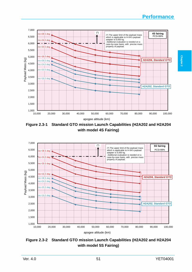
Performance
Ver. 4.0 51 YET04001
Ch
apter 2
Figure 2.3-1 Standard GTO mission Launch Capabilities (H2A202 and H2A204
with model 4S Fairing)
Figure 2.3-2 Standard GTO mission Launch Capabilities (H2A202 and H2A204
with model 5S Fairing)
1,000
1,500
2,000
2,500
3,000
3,500
4,000
4,500
5,000
5,500
6,000
6,500
7,000
10,000 20,000 30,000 40,000 50,000 60,000 70,000 80,000 90,000 100,000
Pa
yloa
d M
ass
(kg)
apogee altitude (km)
inc=28.5 deg
H2A202, Standard GTO
H2A204, Standard GTOinc=16.0 deg
inc=20.0 deg
inc=28.5 deg
inc=16.0 deg
inc=20.0 deg
inc=24.0 deg
5S fairing
PCS=99%(*) The upper limit of the payload masswhich is applicable to H-IIA's payloadadapter is 6,000 kg.Additional evaluation is needed on acase-by-case basis, with precise massproperty of payload.
(*)
inc=24.0 deg
1,000
1,500
2,000
2,500
3,000
3,500
4,000
4,500
5,000
5,500
6,000
6,500
7,000
10,000 20,000 30,000 40,000 50,000 60,000 70,000 80,000 90,000 100,000
Pa
yloa
d M
ass
(kg)
apogee altitude (km)
inc=28.5 deg
H2A202, Standard GTO
H2A204, Standard GTO
inc=16.0 deg
inc=20.0 deg
inc=24.0 deg
inc=28.5 deg
inc=16.0 deg
inc=20.0 deg
inc=24.0 deg
(*) The upper limit of the payload masswhich is applicable to H-IIA's payloadadapter is 6,000 kg.Additional evaluation is needed on acase-by-case basis, with precise massproperty of payload.
(*) 4S fairingPCS=99%
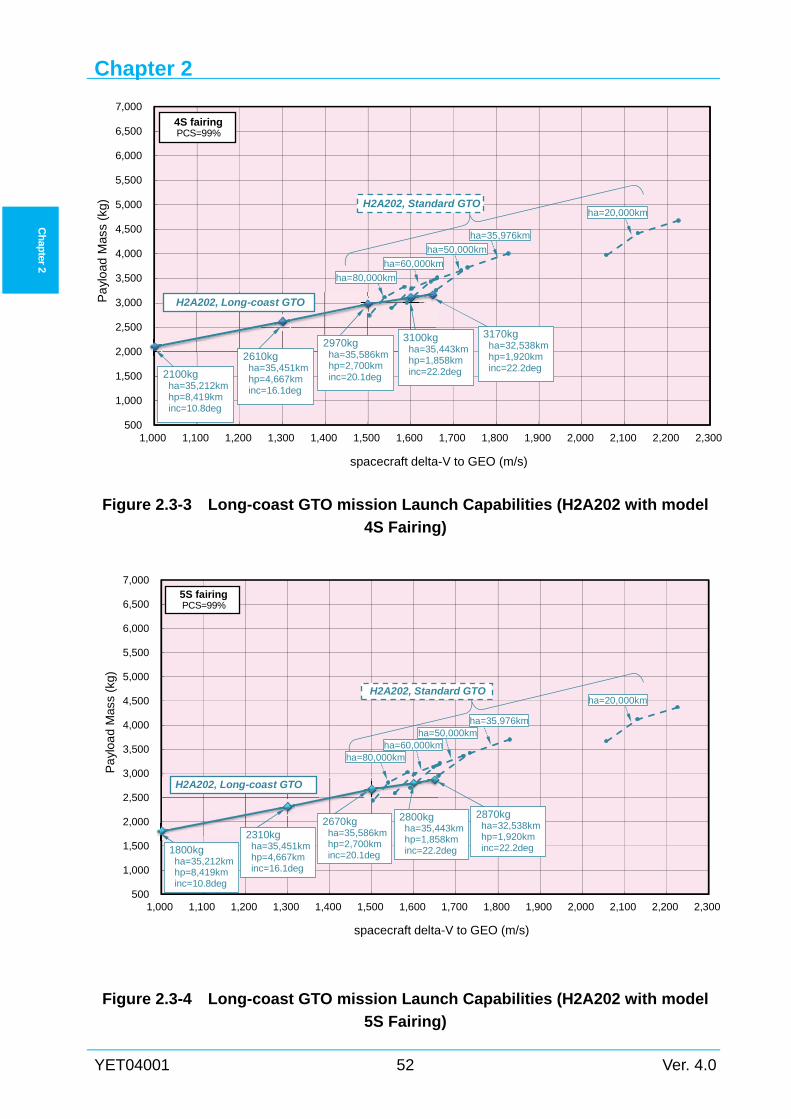
Chapter 2
YET04001 52 Ver. 4.0
Ch
apter 2
Figure 2.3-3 Long-coast GTO mission Launch Capabilities (H2A202 with model
4S Fairing)
Figure 2.3-4 Long-coast GTO mission Launch Capabilities (H2A202 with model
5S Fairing)
500
1,000
1,500
2,000
2,500
3,000
3,500
4,000
4,500
5,000
5,500
6,000
6,500
7,000
1,000 1,100 1,200 1,300 1,400 1,500 1,600 1,700 1,800 1,900 2,000 2,100 2,200 2,300
Pa
yloa
dM
ass
(kg)
spacecraft delta-V to GEO (m/s)
ha=50,000km
1800kgha=35,212kmhp=8,419kminc=10.8deg
2310kgha=35,451kmhp=4,667kminc=16.1deg
2670kgha=35,586kmhp=2,700kminc=20.1deg
2800kgha=35,443kmhp=1,858kminc=22.2deg
2870kgha=32,538kmhp=1,920kminc=22.2deg
H2A202, Long-coast GTO
H2A202, Standard GTO
5S fairingPCS=99%
ha=80,000kmha=60,000km
ha=35,976km
ha=20,000km
500
1,000
1,500
2,000
2,500
3,000
3,500
4,000
4,500
5,000
5,500
6,000
6,500
7,000
1,000 1,100 1,200 1,300 1,400 1,500 1,600 1,700 1,800 1,900 2,000 2,100 2,200 2,300
Pa
ylo
ad M
ass
(kg)
spacecraft delta-V to GEO (m/s)
2100kgha=35,212kmhp=8,419kminc=10.8deg
2610kgha=35,451kmhp=4,667kminc=16.1deg
2970kgha=35,586kmhp=2,700kminc=20.1deg
3100kgha=35,443kmhp=1,858kminc=22.2deg
3170kgha=32,538kmhp=1,920kminc=22.2deg
H2A202, Long-coast GTO
H2A202, Standard GTO
ha=80,000km
ha=60,000km
ha=50,000km
ha=35,976km
ha=20,000km
4S fairingPCS=99%
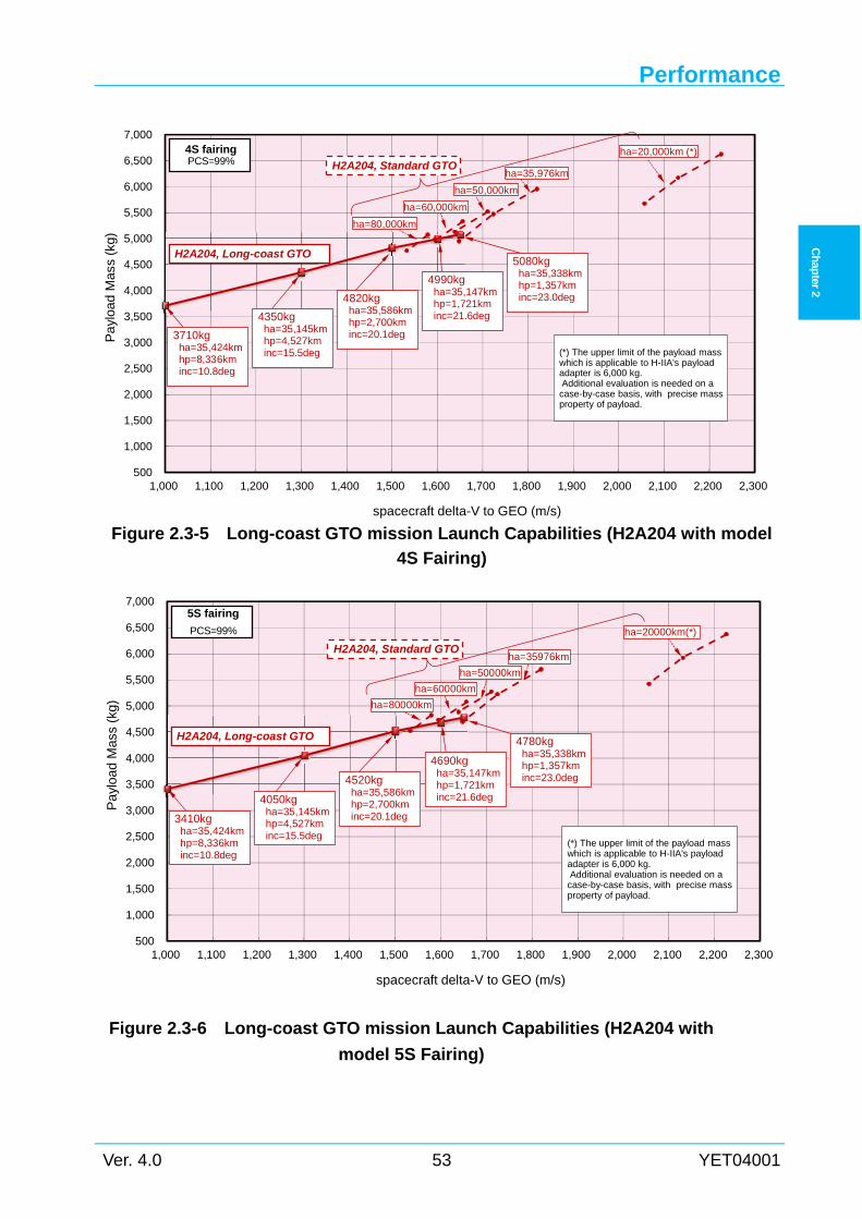
Performance
Ver. 4.0 53 YET04001
Ch
apter 2
Figure 2.3-5 Long-coast GTO mission Launch Capabilities (H2A204 with model
4S Fairing)
Figure 2.3-6 Long-coast GTO mission Launch Capabilities (H2A204 with
model 5S Fairing)
500
1,000
1,500
2,000
2,500
3,000
3,500
4,000
4,500
5,000
5,500
6,000
6,500
7,000
1,000 1,100 1,200 1,300 1,400 1,500 1,600 1,700 1,800 1,900 2,000 2,100 2,200 2,300
Pa
yloa
d M
ass
(kg)
spacecraft delta-V to GEO (m/s)
ha=50,000km
H2A204, Long-coast GTO
H2A204, Standard GTO
4S fairingPCS=99%
ha=20,000km (*)
3710kgha=35,424kmhp=8,336kminc=10.8deg
4350kgha=35,145kmhp=4,527kminc=15.5deg
4820kgha=35,586kmhp=2,700kminc=20.1deg
4990kgha=35,147kmhp=1,721kminc=21.6deg
5080kgha=35,338kmhp=1,357kminc=23.0deg
(*) The upper limit of the payload masswhich is applicable to H-IIA's payloadadapter is 6,000 kg.Additional evaluation is needed on acase-by-case basis, with precise massproperty of payload.
ha=35,976km
ha=60,000km
ha=80,000km
500
1,000
1,500
2,000
2,500
3,000
3,500
4,000
4,500
5,000
5,500
6,000
6,500
7,000
1,000 1,100 1,200 1,300 1,400 1,500 1,600 1,700 1,800 1,900 2,000 2,100 2,200 2,300
Pa
yloa
d M
ass
(kg)
spacecraft delta-V to GEO (m/s)
H2A204, Long-coast GTO
H2A204, Standard GTO
5S fairing
PCS=99% ha=20000km(*)
3410kgha=35,424kmhp=8,336kminc=10.8deg
4050kgha=35,145kmhp=4,527kminc=15.5deg
4520kgha=35,586kmhp=2,700kminc=20.1deg
4690kgha=35,147kmhp=1,721kminc=21.6deg
4780kgha=35,338kmhp=1,357kminc=23.0deg
(*) The upper limit of the payload masswhich is applicable to H-IIA's payloadadapter is 6,000 kg.Additional evaluation is needed on acase-by-case basis, with precise massproperty of payload.
ha=80000km
ha=50000km
ha=60000km
ha=35976km
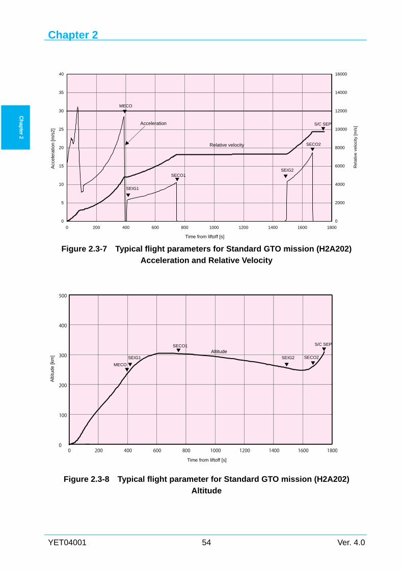
Chapter 2
YET04001 54 Ver. 4.0
Ch
apter 2
Figure 2.3-7 Typical flight parameters for Standard GTO mission (H2A202)
Acceleration and Relative Velocity
Figure 2.3-8 Typical flight parameter for Standard GTO mission (H2A202)
Altitude
0 200 400 600 800 1000 1200 1400 1600 18000
100
200
300
400
500
Time from liftoff [s]
MECO
SEIG1 SECO2
S/C SEP
AltitudeSEIG2
SECO1
Alti
tude
[km
]
0
5
10
15
20
25
30
35
40
0 200 400 600 800 1000 1200 1400 1600 1800
0
2000
4000
6000
8000
10000
12000
14000
16000
Acc
eler
atio
n [m
/s2]
Time from liftoff [s]
MECO
SEIG1
SECO2
S/C SEP
Relative velocity
SEIG2SECO1
Rel
ativ
e v
elo
city
[m/s
]
Acceleration
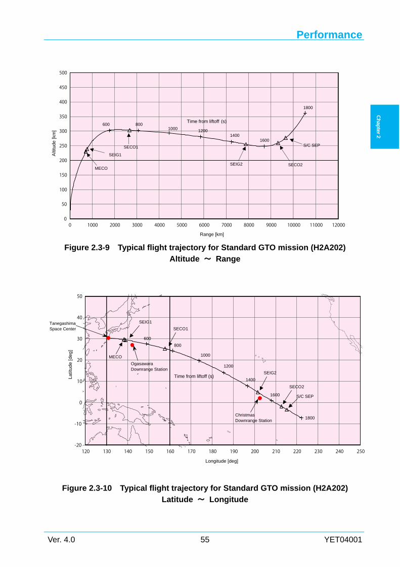
Performance
Ver. 4.0 55 YET04001
Ch
apter 2
Figure 2.3-9 Typical flight trajectory for Standard GTO mission (H2A202)
Altitude ~ Range
Figure 2.3-10 Typical flight trajectory for Standard GTO mission (H2A202)
Latitude ~ Longitude
-20
-10
0
10
20
30
40
50
120 130 140 150 160 170 180 190 200 210 220 230 240 250
Latit
ude
[de
g]
Longitude [deg]
SEIG2Time from liftoff (s)
1800
600
SECO2
S/C SEP
MECO
1600
1000
SECO1
SEIG1
1400
1200
800
OgasawaraDownrange Station
ChristmasDownrange Station
TanegashimaSpace Center
0
50
100
150
200
250
300
350
400
450
500
0 1000 2000 3000 4000 5000 6000 7000 8000 9000 10000 11000 12000
Alti
tude
[km
]
Range [km]
MECO
SEIG1
SECO2
S/C SEP
Time from liftoff (s)600
1000
1800
1600
SEIG2
SECO1
14001200
800
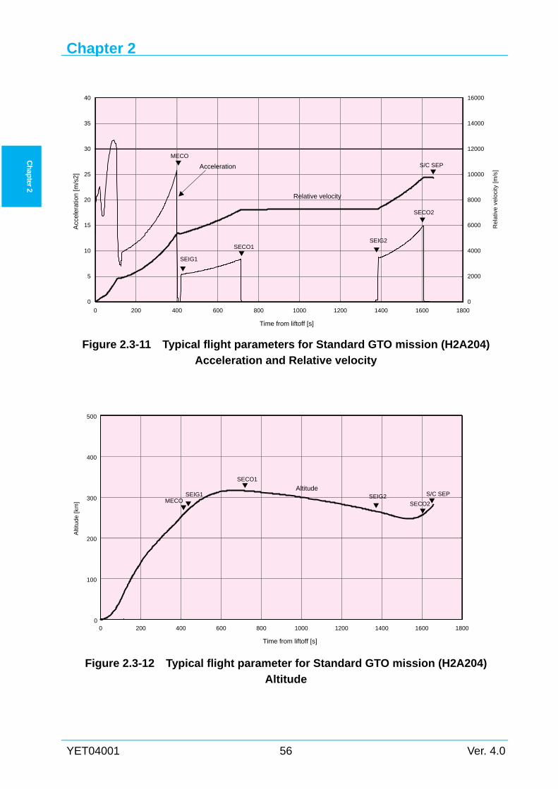
Chapter 2
YET04001 56 Ver. 4.0
Ch
apter 2
Figure 2.3-11 Typical flight parameters for Standard GTO mission (H2A204)
Acceleration and Relative velocity
Figure 2.3-12 Typical flight parameter for Standard GTO mission (H2A204)
Altitude
0
5
10
15
20
25
30
35
40
0 200 400 600 800 1000 1200 1400 1600 1800
0
2000
4000
6000
8000
10000
12000
14000
16000
Acc
eler
atio
n [m
/s2]
Time from liftoff [s]
MECO
SEIG1
SECO2
S/C SEP
Relative velocity
SEIG2SECO1
Re
lativ
e v
elo
city
[m/s
]
Acceleration
0 200 400 600 800 1000 1200 1400 1600 18000
100
200
300
400
500
Time from liftoff [s]
Altitude
Alti
tude
[km
] MECOSEIG1
SECO2
S/C SEPSEIG2
SECO1
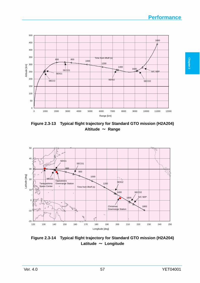
Performance
Ver. 4.0 57 YET04001
Ch
apter 2
Figure 2.3-13 Typical flight trajectory for Standard GTO mission (H2A204)
Altitude ~ Range
Figure 2.3-14 Typical flight trajectory for Standard GTO mission (H2A204)
Latitude ~ Longitude
-20
-10
0
10
20
30
40
50
120 130 140 150 160 170 180 190 200 210 220 230 240 250
Latit
ude
[de
g]
Longitude [deg]
SEIG2
Time from liftoff (s)
1800
600
SECO2
S/C SEP
MECO
1600
1000
SECO1SEIG1
1400
1200
800
OgasawaraDownrange Station
ChristmasDownrange Station
TanegashimaSpace Center
0
50
100
150
200
250
300
350
400
450
500
0 1000 2000 3000 4000 5000 6000 7000 8000 9000 10000 11000 12000
Alti
tude
[km
]
Range [km]
MECO
SEIG1
SECO2
S/C SEP
Time from liftoff (s)600
1000
1800
1600
SEIG2
SECO1
1400
1200
800
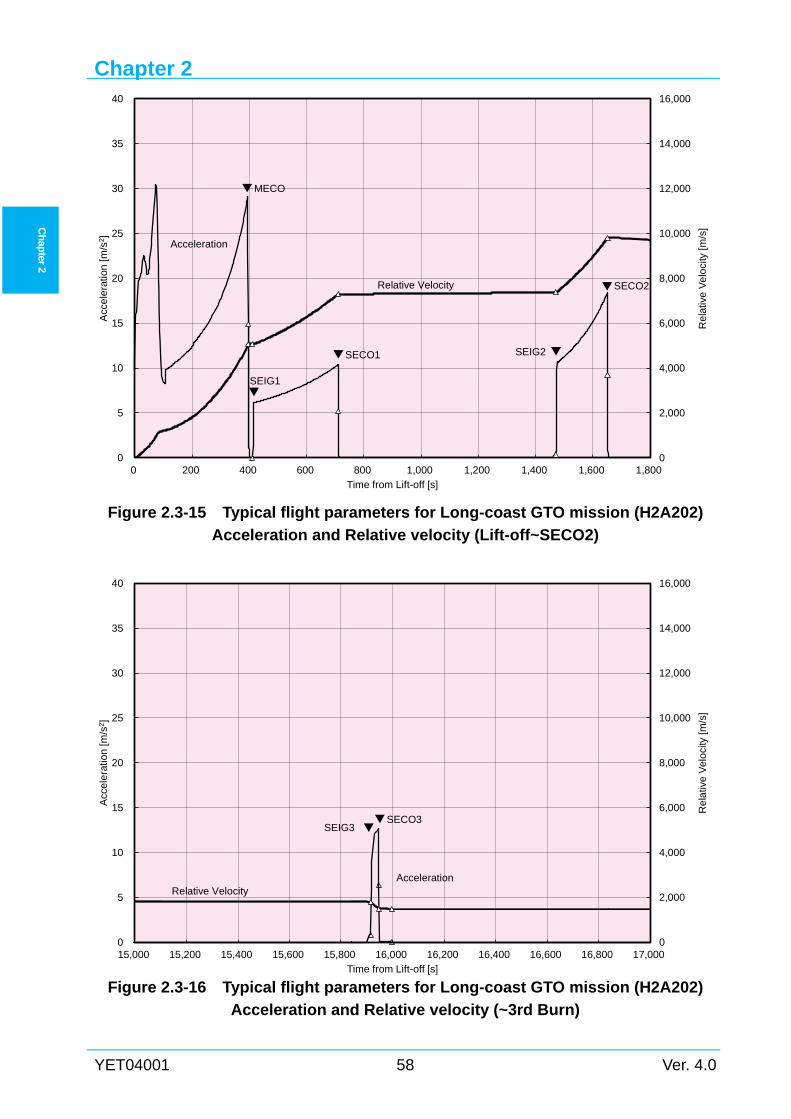
Chapter 2
YET04001 58 Ver. 4.0
Ch
apter 2
Figure 2.3-15 Typical flight parameters for Long-coast GTO mission (H2A202)
Acceleration and Relative velocity (Lift-off~SECO2)
Figure 2.3-16 Typical flight parameters for Long-coast GTO mission (H2A202)
Acceleration and Relative velocity (~3rd Burn)
0
2,000
4,000
6,000
8,000
10,000
12,000
14,000
16,000
0
5
10
15
20
25
30
35
40
15,000 15,200 15,400 15,600 15,800 16,000 16,200 16,400 16,600 16,800 17,000
Re
lativ
eV
elo
city
[m/s
]
Acc
ele
ratio
n[m
/s2 ]
Time from Lift-off [s]
AccelerationRelative Velocity
SECO3SEIG3
0
2,000
4,000
6,000
8,000
10,000
12,000
14,000
16,000
0
5
10
15
20
25
30
35
40
0 200 400 600 800 1,000 1,200 1,400 1,600 1,800
Re
lativ
eV
elo
city
[m/s
]
Acc
ele
ratio
n[m
/s2 ]
Time from Lift-off [s]
Acceleration
Relative Velocity
MECO
SEIG1
SECO1 SEIG2
SECO2
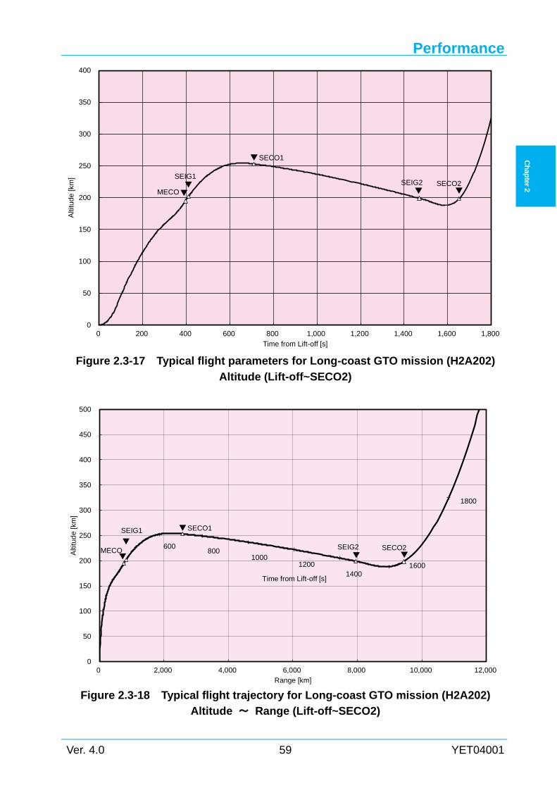
Performance
Ver. 4.0 59 YET04001
Ch
apter 2
Figure 2.3-17 Typical flight parameters for Long-coast GTO mission (H2A202)
Altitude (Lift-off~SECO2)
Figure 2.3-18 Typical flight trajectory for Long-coast GTO mission (H2A202)
Altitude ~ Range (Lift-off~SECO2)
0
50
100
150
200
250
300
350
400
450
500
0 2,000 4,000 6,000 8,000 10,000 12,000
Alti
tud
e[k
m]
Range [km]
Time from Lift-off [s]
600
1800
16001400
12001000
800MECO
SEIG1 SECO1
SEIG2 SECO2
0
50
100
150
200
250
300
350
400
0 200 400 600 800 1,000 1,200 1,400 1,600 1,800
Alti
tud
e[k
m]
Time from Lift-off [s]
MECO
SEIG1
SECO1
SEIG2 SECO2
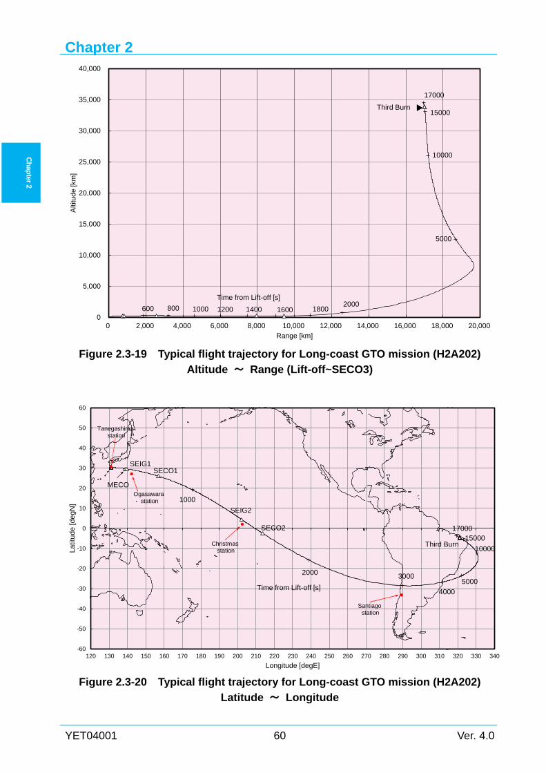
Chapter 2
YET04001 60 Ver. 4.0
Ch
apter 2
Figure 2.3-19 Typical flight trajectory for Long-coast GTO mission (H2A202)
Altitude ~ Range (Lift-off~SECO3)
Figure 2.3-20 Typical flight trajectory for Long-coast GTO mission (H2A202)
Latitude ~ Longitude
-60
-50
-40
-30
-20
-10
0
10
20
30
40
50
60
120 130 140 150 160 170 180 190 200 210 220 230 240 250 260 270 280 290 300 310 320 330 340
La
titu
de
[de
gN]
Longitude [degE]
MECO
SEIG1SECO1
SEIG2
SECO2
1000
4000
30002000
1700015000
10000
5000
Third Burn
Time from Lift-off [s]
Tanegashimastation
Ogasawarastation
Christmasstation
Santiagostation
0
5,000
10,000
15,000
20,000
25,000
30,000
35,000
40,000
0 2,000 4,000 6,000 8,000 10,000 12,000 14,000 16,000 18,000 20,000
Alti
tud
e[k
m]
Range [km]
Time from Lift-off [s]
Third Burn
600 180016001400120010008002000
17000
15000
10000
5000
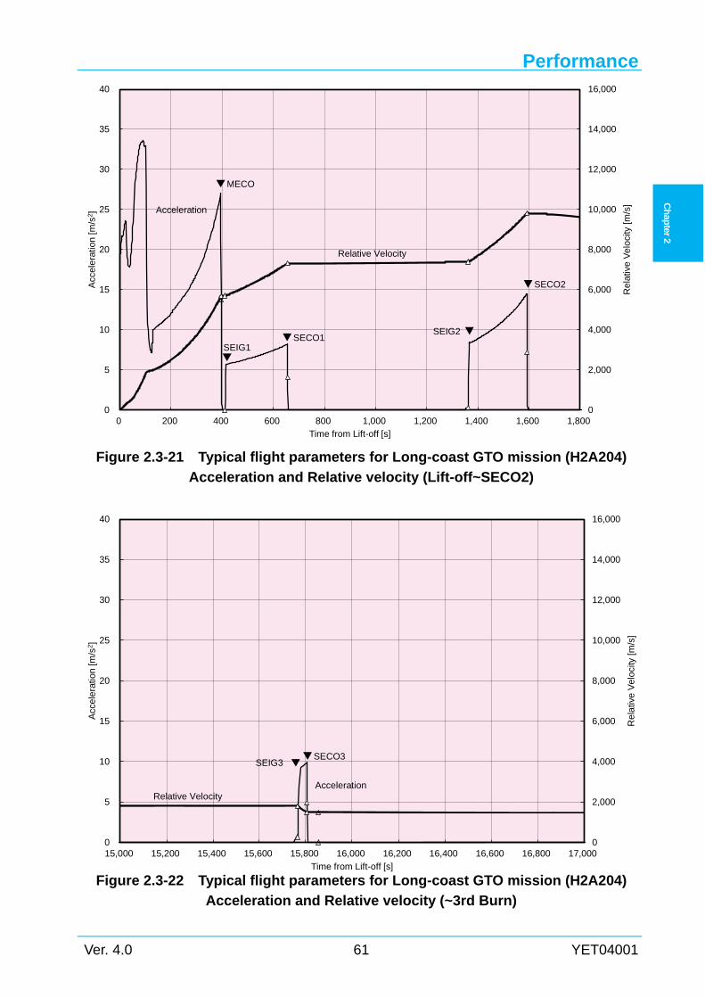
Performance
Ver. 4.0 61 YET04001
Ch
apter 2
Figure 2.3-21 Typical flight parameters for Long-coast GTO mission (H2A204)
Acceleration and Relative velocity (Lift-off~SECO2)
Figure 2.3-22 Typical flight parameters for Long-coast GTO mission (H2A204)
Acceleration and Relative velocity (~3rd Burn)
0
2,000
4,000
6,000
8,000
10,000
12,000
14,000
16,000
0
5
10
15
20
25
30
35
40
15,000 15,200 15,400 15,600 15,800 16,000 16,200 16,400 16,600 16,800 17,000
Re
lativ
eV
elo
city
[m/s
]
Acc
ele
ratio
n[m
/s2]
Time from Lift-off [s]
AccelerationRelative Velocity
SECO3SEIG3
0
2,000
4,000
6,000
8,000
10,000
12,000
14,000
16,000
0
5
10
15
20
25
30
35
40
0 200 400 600 800 1,000 1,200 1,400 1,600 1,800
Rel
ativ
eV
elo
city
[m/s
]
Acc
ele
ratio
n[m
/s2 ]
Time from Lift-off [s]
Acceleration
Relative Velocity
MECO
SEIG1SECO1
SEIG2
SECO2
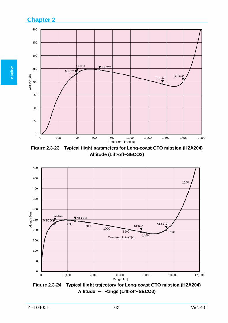
Chapter 2
YET04001 62 Ver. 4.0
Ch
apter 2
Figure 2.3-23 Typical flight parameters for Long-coast GTO mission (H2A204)
Altitude (Lift-off~SECO2)
Figure 2.3-24 Typical flight trajectory for Long-coast GTO mission (H2A204)
Altitude ~ Range (Lift-off~SECO2)
0
50
100
150
200
250
300
350
400
450
500
0 2,000 4,000 6,000 8,000 10,000 12,000
Alti
tud
e[k
m]
Range [km]
Time from Lift-off [s]
600
1800
16001400
12001000
800
MECO
SEIG1SECO1
SEIG2 SECO2
0
50
100
150
200
250
300
350
400
0 200 400 600 800 1,000 1,200 1,400 1,600 1,800
Alti
tud
e[k
m]
Time from Lift-off [s]
MECO
SEIG1 SECO1
SEIG2SECO2
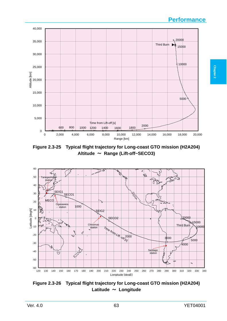
Performance
Ver. 4.0 63 YET04001
Ch
apter 2
Figure 2.3-25 Typical flight trajectory for Long-coast GTO mission (H2A204)
Altitude ~ Range (Lift-off~SECO3)
Figure 2.3-26 Typical flight trajectory for Long-coast GTO mission (H2A204)
Latitude ~ Longitude
-60
-50
-40
-30
-20
-10
0
10
20
30
40
50
60
120 130 140 150 160 170 180 190 200 210 220 230 240 250 260 270 280 290 300 310 320 330 340
Lat
itud
e[d
egN
]
Longitude [degE]
MECO
SEIG1SECO1
SEIG2
SECO2
1000
4000
30002000
20000
15000
10000
5000
Third BurnTime from Lift -off [s]
Tanegashimastation
Ogasawarastation
Christmasstation
Santiagostation
0
5,000
10,000
15,000
20,000
25,000
30,000
35,000
40,000
0 2,000 4,000 6,000 8,000 10,000 12,000 14,000 16,000 18,000 20,000
Alti
tud
e[k
m]
Range [km]
Time from Lift-off [s]
Third Burn
600 180016001400120010008002000
20000
15000
10000
5000
Chapter 2
YET04001 64 Ver. 4.0
Ch
apter 2
2.4 Sun Synchronous Orbit (SSO) Mission
2.4.1 Launch capability Payload mass with model 4S fairing for SSO mission is approximately 3,300 kg based on
orbital parameters in Section 2.4-2.
With model 5S fairing, the payload mass decreases by 300 kg approximately.
Launch capability of H2A202 with model 4S fairing for SSO mission is shown in Figure
2.4-1.
2.4.2 Typical orbital parameters Typical orbital parameters for SSO mission are as follows :
Circular orbit altitude h = 800.0 km
Inclination i = 98.6 deg
2.4.3 Injection accuracies Typical injection accuracies for SSO mission are as follows based on parameters in Section
2.4.2.
Semi-major axis a = ± 10.0 km
Inclination i = ± 0.18 deg
Eccentricity e = 0 ~ 0.001
(These values are 3-sigma level.)
2.4.4 Typical trajectory Typical flight trajectory of H2A202 with model 4S fairing for SSO mission is shown in Figure
2.4-2.
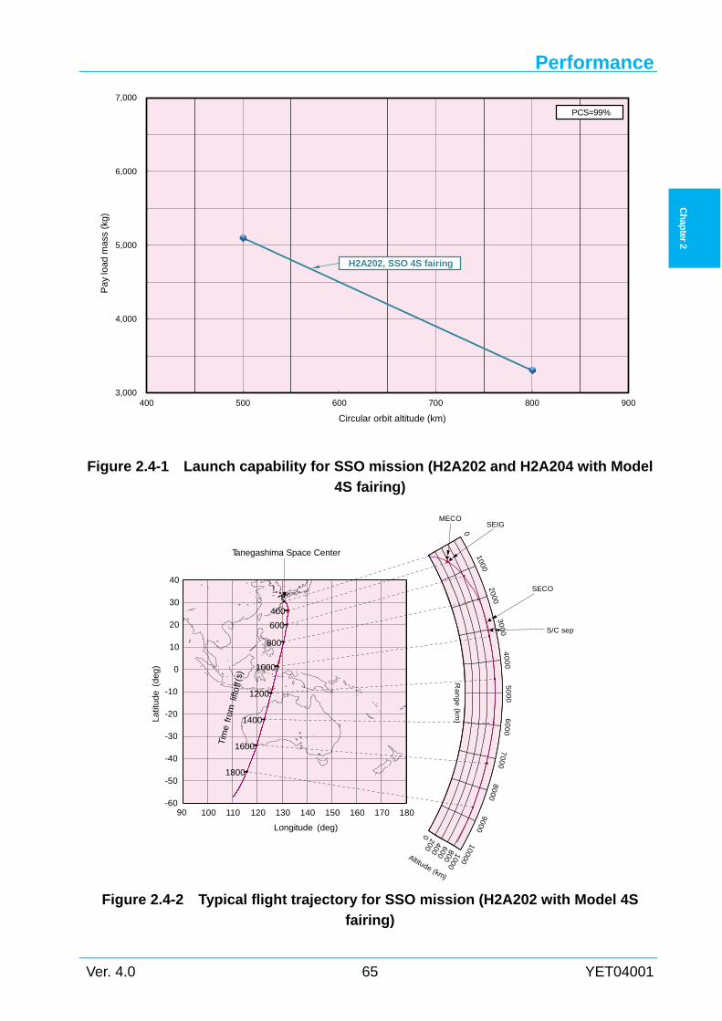
Performance
Ver. 4.0 65 YET04001
Ch
apter 2
Figure 2.4-1 Launch capability for SSO mission (H2A202 and H2A204 with Model
4S fairing)
Figure 2.4-2 Typical flight trajectory for SSO mission (H2A202 with Model 4S
fairing)
3,000
4,000
5,000
6,000
7,000
400 500 600 700 800 900
Pa
y lo
adm
ass
(kg)
Circular orbit altitude (km)
H2A202, SSO 4S fairing
PCS=99%
100 110 120 130 140 150 160 170 180-60
-50
-40
-30
-20
-10
0
10
20
30
40
0
0 200 400 600 800 1000
Altitude (km)
SEIGMECO
SECO
S/C sep
400
600
800
1000
1200
1400
1600
1800
Tim
efr
omlif
toff
(s)
Latit
ude
(deg)
Longitude (deg)
Tanegashima Space Center
90
100020
00
30
00
40
00
50
00
60
00
70
00
800
09000
10000R
an
ge
(km)
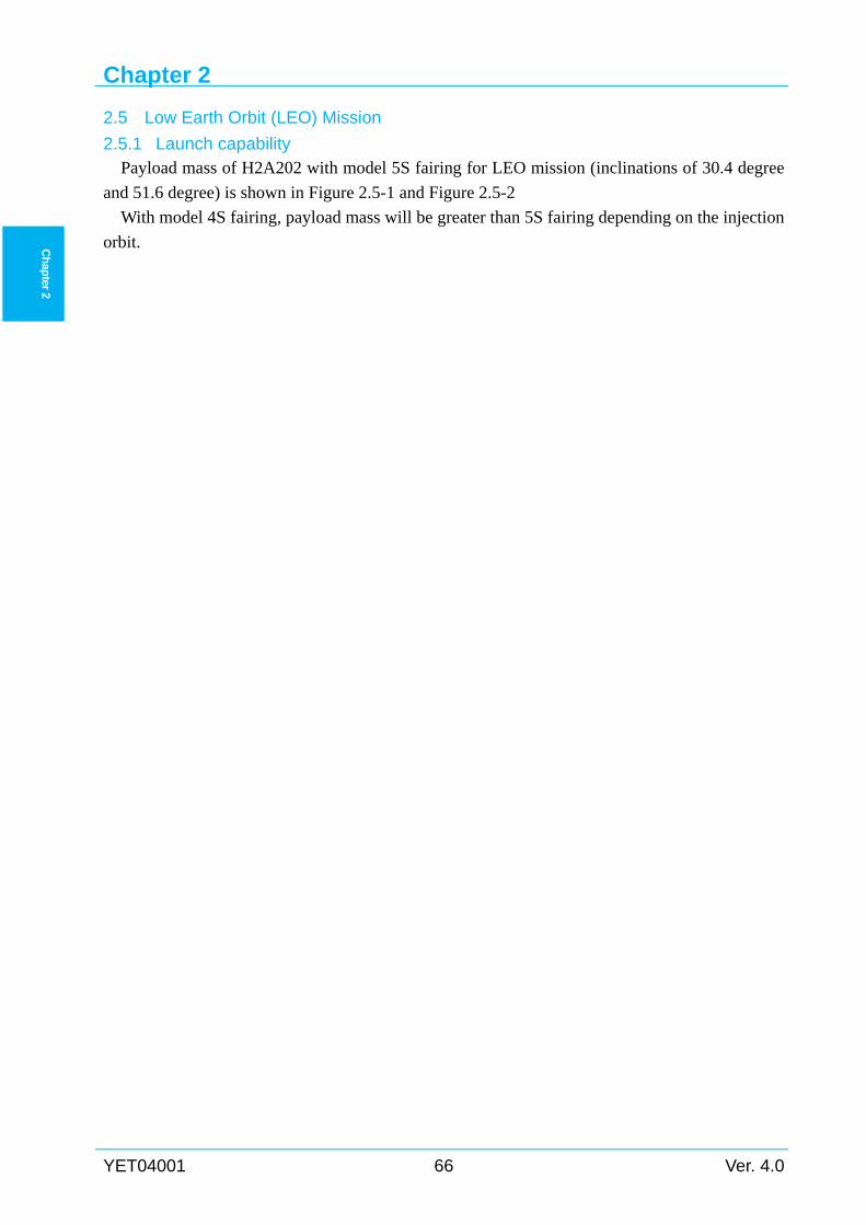
Chapter 2
YET04001 66 Ver. 4.0
Ch
apter 2
2.5 Low Earth Orbit (LEO) Mission
2.5.1 Launch capability Payload mass of H2A202 with model 5S fairing for LEO mission (inclinations of 30.4 degree
and 51.6 degree) is shown in Figure 2.5-1 and Figure 2.5-2
With model 4S fairing, payload mass will be greater than 5S fairing depending on the injection
orbit.
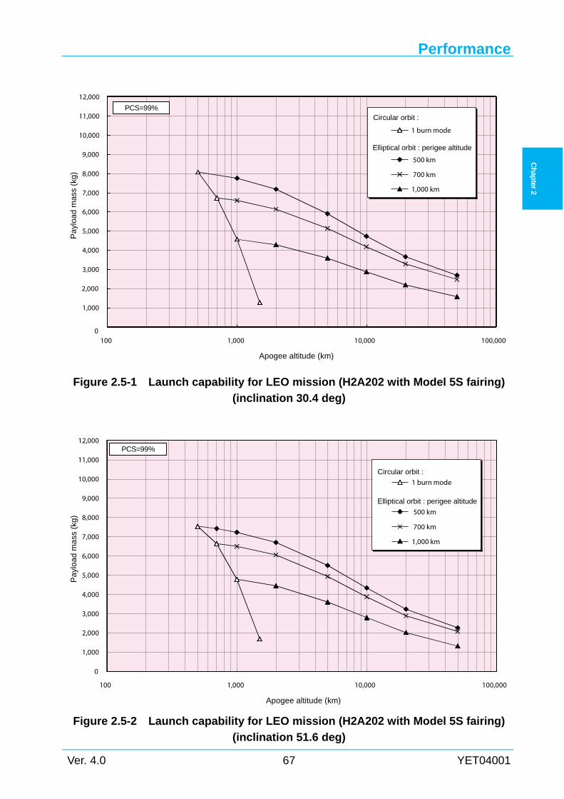
Performance
Ver. 4.0 67 YET04001
Ch
apter 2
Figure 2.5-1 Launch capability for LEO mission (H2A202 with Model 5S fairing)
(inclination 30.4 deg)
Figure 2.5-2 Launch capability for LEO mission (H2A202 with Model 5S fairing)
(inclination 51.6 deg)
0
1,000
2,000
3,000
4,000
5,000
6,000
7,000
8,000
9,000
10,000
11,000
12,000
100 1,000 10,000 100,000
Apogee altitude (km)
Pa
yloa
d m
ass
(kg
)
1 burn mode
500 km
700 km
1,000 km
Elliptical orbit : perigee altitude
Circular orbit :PCS=99%
0
1,000
2,000
3,000
4,000
5,000
6,000
7,000
8,000
9,000
10,000
11,000
12,000
100 1,000 10,000 100,000
Apogee altitude (km)
Pa
ylo
ad
ma
ss (
kg)
1 burn mode
500 km
700 km
1,000 km
Elliptical orbit : perigee altitude
Circular orbit :
PCS=99%
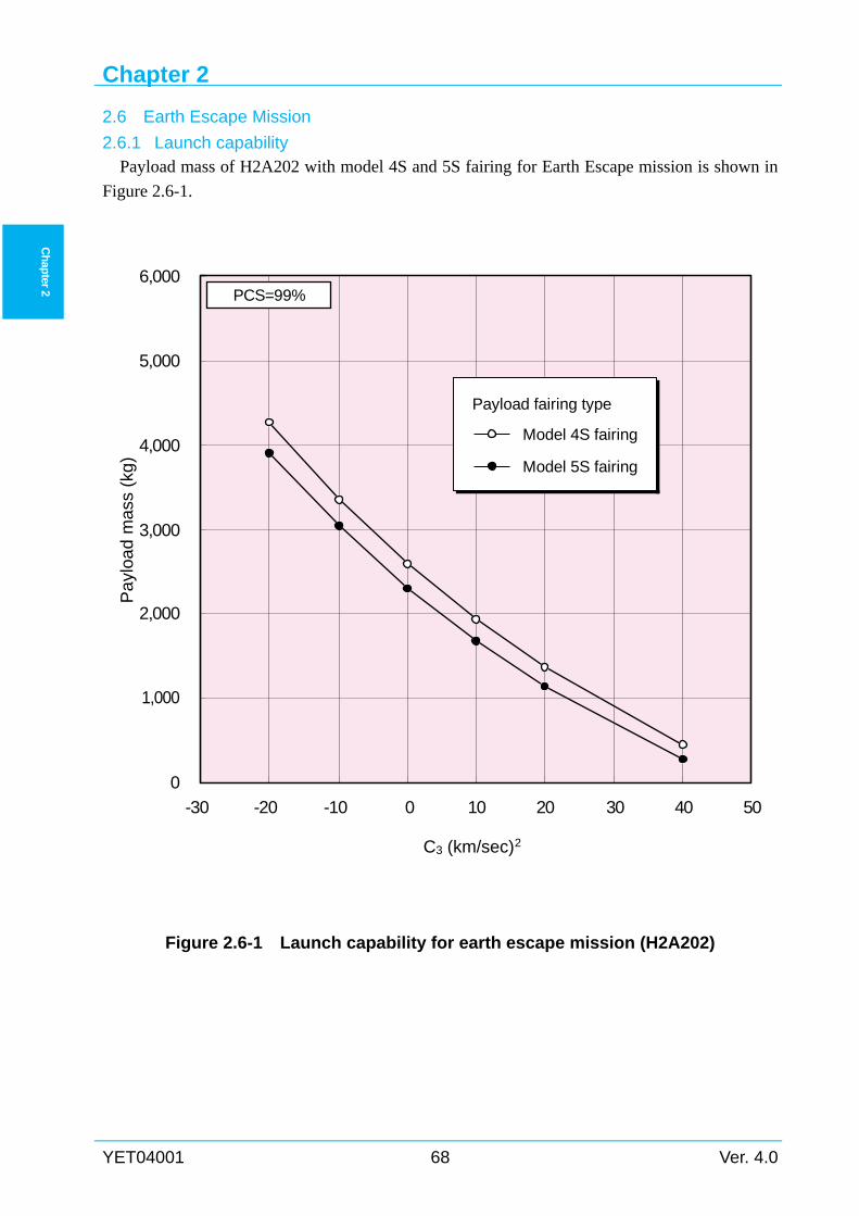
Chapter 2
YET04001 68 Ver. 4.0
Ch
apter 2
2.6 Earth Escape Mission
2.6.1 Launch capability Payload mass of H2A202 with model 4S and 5S fairing for Earth Escape mission is shown in
Figure 2.6-1.
Figure 2.6-1 Launch capability for earth escape mission (H2A202)
0
1,000
2,000
3,000
4,000
5,000
6,000
-30 -20 -10 0 10 20 30 40 50
C3 (km/sec)2
Pa
yloa
d m
ass
(kg
)
Model 4S fairing
Model 5S fairing
Payload fairing type
PCS=99%
Performance
Ver. 4.0 69 YET04001
Ch
apter 2
2.7 Spacecraft Orientation and Separation
2.7.1 General description When injected into the planned orbit, the second stage provides the spacecraft with required
orientation and spin-up (if required, see Section 2.7.3) prior to separation.
Following the spacecraft separation, CCAM is performed to avoid collision and contamination
to the spacecraft.
2.7.2 Separation sequence (1) Before separation
The second stage attitude is controlled by the guidance and control system according to the
mission plan (desired direction, program rate and sequence) with respect to three axis direction
using the reaction control (gas jet) system (RCS).
(2) Separation
The second stage guidance control computer (GCC2) sends the separation command to the
second stage sequence distribution box (SDB2), and SDB2 sends an ignition current to the
separation system (pyrotechnics of clamp band or separation nuts).
The separation is monitored by two (2) separation switches located at the top of the adapter.
The separation switches sense the spacecraft separation, and telemetry sends the separation event
data to the ground station.
The separation mechanism is by separation spring.
(3) After separation
After spacecraft separation, the second stage conducts the CCAM using the RCS and the
residual GH2 in the LH2 tank (residual GHe in the ambient helium bottle is used.)
2.7.3 Spin-up performance The second stage RCS can provide a roll spin for spacecraft with angular velocity up to 5 rpm
clockwise or counterclockwise before spacecraft separation. If SCO requires spacecraft spin-up,
details should be coordinated with LSP.
Chapter 2
YET04001 70 Ver. 4.0
Ch
apter 2
2.7.4 Pointing accuracy Pointing accuracy (deviation from the nominal value) just before spacecraft separation is
shown below.
Without pointing maneuver : Less than ± 10 deg
With pointing maneuver : Less than ± 3 deg
<Note> These values are:
-around roll, pitch and yaw axes.
-accuracies before spin-up occurs if spin-up is requested.
2.7.5 Relative separation velocity Relative velocity at spacecraft separation is approximately 0.5 to 1.0 m/s. Other velocity is
possible per SCO's request as far as it does not affect launch vehicle collision avoidance
maneuvers.
For analyzing the spacecraft/launch vehicle relative orbit, SCO is requested to provide a
spacecraft orbit and attitude control plan after separation.
2.7.6 Separation tip-off rate Separation tip-off rate varies depending on the spacecraft physical characteristic.
The spacecraft is ejected by the spring ejection mechanism installed on payload adapter and
typical tip-off rate is less than 2.0 deg/s.
2.7.7 Dual launch sequence Separation sequence for dual launch is shown as below.
- LEO (upper)-GTO (lower) mission : Figure 2.7-1
- GTO (upper)-GTO (lower) mission : Figure 2.7-2
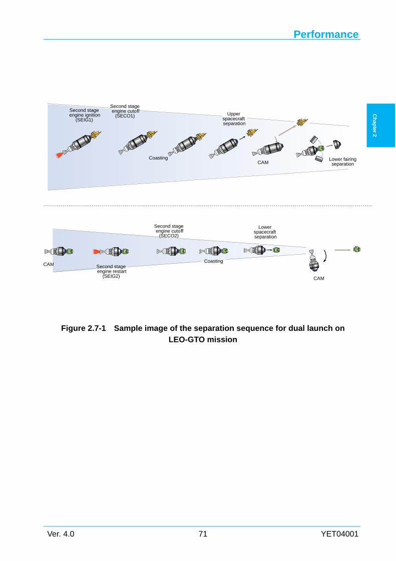
Performance
Ver. 4.0 71 YET04001
Ch
apter 2
Figure 2.7-1 Sample image of the separation sequence for dual launch on
LEO-GTO mission
Second stage engine restart
(SEIG2)
Coasting
Second stage engine cutoff
(SECO2)
Coasting
Upperspacecraft separation
Lowerspacecraft separation
Lower fairingseparationCAM
CAM
Second stage engine ignition
(SEIG1)
Second stage engine cutoff
(SECO1)
CAM
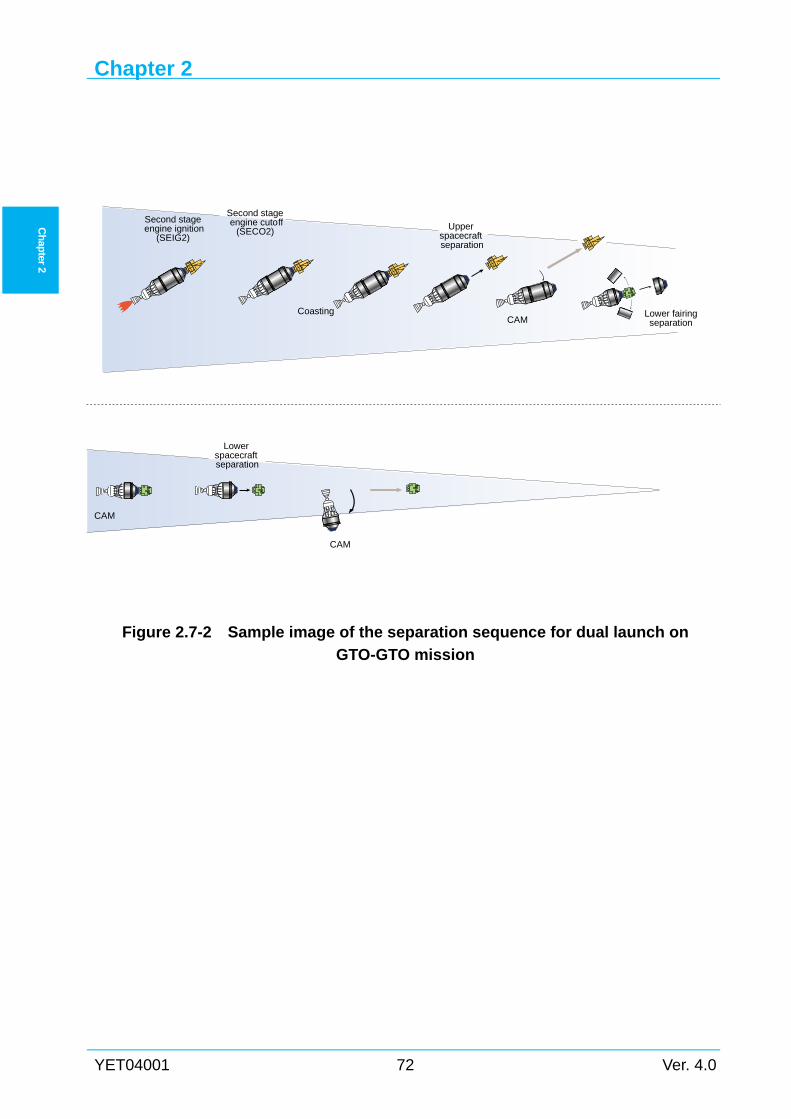
Chapter 2
YET04001 72 Ver. 4.0
Ch
apter 2
Figure 2.7-2 Sample image of the separation sequence for dual launch on
GTO-GTO mission
Coasting
Upperspacecraft separation
Lowerspacecraft separation
Lower fairingseparationCAM
CAM
Second stage engine ignition
(SEIG2)
Second stage engine cutoff
(SECO2)
CAM
Chapter 3
Ver. 4.0 73 YET04001
Ch
apter 3
Chapter 3 ENVIRONMENTS
General 3.1This chapter describes the environments to which the spacecraft will be exposed in prelaunch
and flight phases. The spacecraft has to be designed and tested before launch according to these
conditions. Therefore, spacecraft test requirements are also described.
Mechanical Environments 3.2
3.2.1 General During liftoff and in-flight phases, the spacecraft is exposed to static and dynamic loads
caused by the launch vehicle. These environments cover the phases of ground transportation in
Tanegashima Island (including transportation to the launch pad), encapsulation of the spacecraft
and mounting spacecraft on the second stage. The load factors described in Section 3.2.2 to 3.2.5
should be considered as limit loads applied to the spacecraft.
3.2.2 Combined load factor Figure2.3-7, Figure2.3-11, Figure2.3-15, Figure2.3-16, Figure2.3-21, and Figure2.3-22 show
typical longitudinal static acceleration flight time history.
During liftoff and in-flight phases, dynamic acceleration excited by aerodynamic factors (such
as winds, buffeting at transonic phase) and / or forces of the propulsion systems (thrust buildup
or tail-off transients of the first stage main engine or SRB-A, etc.) is imposed on the spacecraft.
So a combination of static acceleration (the quasi-static acceleration) and low-frequency
dynamic acceleration should be considered as the design limit load factors for the spacecraft
primary structure.
For the H-IIA launch vehicle, the combined load factor at liftoff and at main engine (of the
first stage) cutoff (MECO) transient cover the maximum loads of the spacecraft primary
structure during liftoff and in-flight phases.
Table 3.2-1 shows the load factors of 3-sigma high values. Lateral and longitudinal loads may
act simultaneously during any phase.
For secondary structures of the spacecraft which have low natural frequencies, load factor on
the structures may exceed the above load factors. The acceleration distribution within the
spacecraft should be determined using the Coupled Loads Analysis (CLA) results. For more
information regarding the CLA, please contact LSP .
Chapter 3
YET04001 74 Ver. 4.0
Ch
apter 3
3.2.3 Sinusoidal vibration The spacecraft is exposed to vibration environment that may be divided into two general
frequency ranges as follows:
(1) low-frequency sinusoidal vibration
(2) high-frequency random vibration
In this section, (1) is described. And (2) is described in Section 3.2.4 or 3.2.5.
The levels shown in Table3.2-2 are enveloped levels of the low frequency vibrations which
are exerted during liftoff and in-flight phases, in particular at liftoff, maximum Qα’ (which
means the maximum product of dynamic pressure and total angle of attack), the first and the
second stage separation, second stage steady state burn, etc. These levels are prescribed at the
spacecraft interface (spacecraft separation plane). The second stage steady state burn
longitudinal vibration mode appears remarkably on lightweight spacecraft. To reduce the
vibration, passive damping device is available for lightweight spacecraft. For more information
regarding the sinusoidal vibration, please contact LSP.
These conditions do not include the influence of steady acceleration, therefore additional
evaluations for this influence are necessary.
If there is possibility during testing that the structure is subjected to overloads due to
differences between the flight configuration and the vibration test configuration, a notching
procedure will be allowed to avoid overloads. Notching conditions should be based on the CLA.
When sinusoidal vibration environmental test cannot simulate the dynamic load of the flight
condition sufficiently, please contact LSP.
3.2.4 Random vibration Spacecraft structure experiences the random vibration (high-frequency), which is primarily
caused by the acoustic noise described in Section 3.2.5. If random vibration conditions at the
base of the spacecraft are required, please contact LSP.
3.2.5 Acoustics The spacecraft is exposed to an acoustic environment during the first stage phase until the
vehicle ascends to the altitude where an atmospheric influence can be disregarded. Random
vibrations are generated by the noise of the first stage main engine and the SRB-A, and the
pressure vibration caused by buffeting and boundary layer noise during the phase of the
transonic flight and the high dynamic pressure.
Table 3.2-3 and Table 3.2-4 show the acoustic environment level inside the payload fairing for
H2A202 and H2A204 respectively. This is the envelope level during launch and flight and
defined as 2-sigma high. This level is uniform around the spacecraft. The spacecraft should
endure this level for 40 seconds. The reference point 0 dB of sound pressure level (SPL) is
equivalent to 20 μPa. The filling effect is not included in these acoustic environment levels.
Environments
Ver. 4.0 75 YET04001
Ch
apter 3
Regarding acoustic environment, please contact LSP for details.
3.2.6 Shock Table 3.2-5 shows a summary of pyrotechnic shock events during flight on all kinds of the
H-IIA launch vehicle. A type and a location of each separation system are different according to
each shock event. In these separation systems, the spacecraft separation device located at the
spacecraft separation plane produces the highest shock.
Figure 3.2-1 and Figure 3.2-2 show a typical separation shock spectrum at the spacecraft
separation plane with 1194M adapter and 1666MA adapter, respectively. These shock spectrums
are exerted uniformly in all directions.
Low shock adapters (937LS-H, 1194LS-H, 1666LS-H) can be provided. Figure 3.2-3 shows a
typical spacecraft separation shock spectrum at the spacecraft separation plane with 1194LS-H
adapter.
If SCO desires to use another familiar adapter, LSP can procure the customer requested
adapter. Please contact LSP for details.
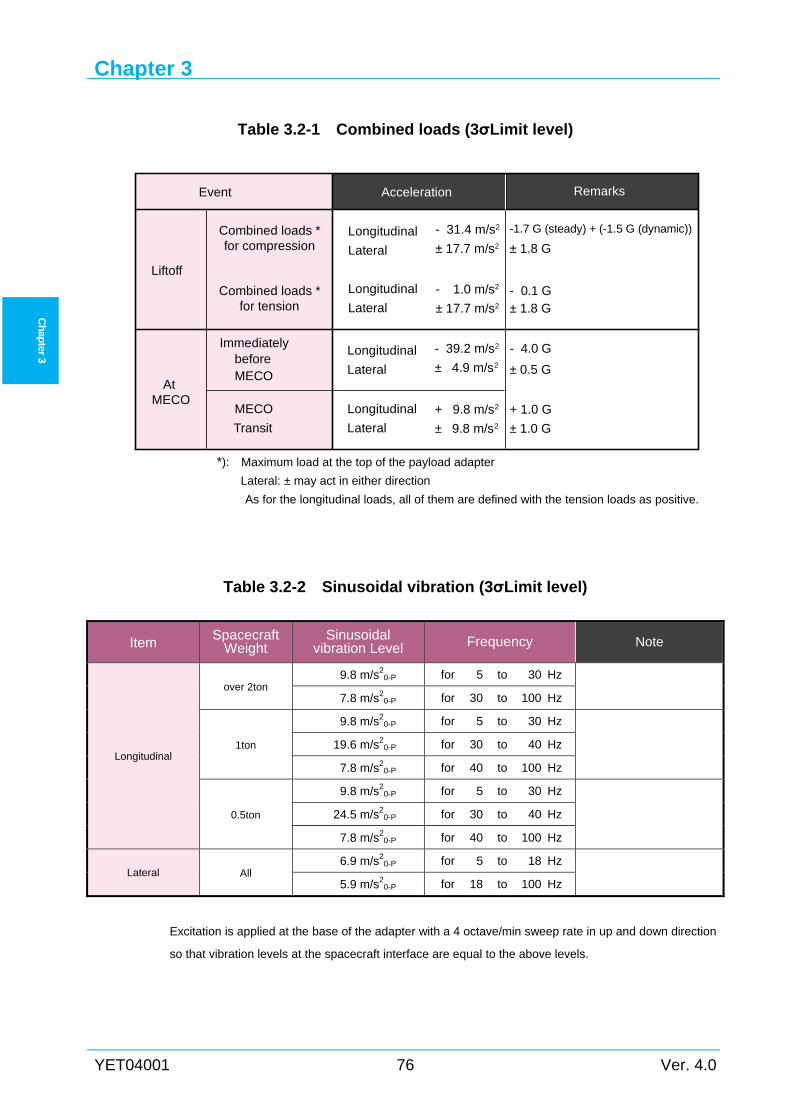
Chapter 3
YET04001 76 Ver. 4.0
Ch
apter 3
Table 3.2-1 Combined loads (3σLimit level)
*): Maximum load at the top of the payload adapter
Lateral: ± may act in either direction
As for the longitudinal loads, all of them are defined with the tension loads as positive.
Table 3.2-2 Sinusoidal vibration (3σLimit level)
Item Spacecraft Weight
Sinusoidal vibration Level Frequency Note
Longitudinal
over 2ton 9.8 m/s2
0-P for 5 to 30 Hz
7.8 m/s20-P for 30 to 100 Hz
1ton
9.8 m/s20-P for 5 to 30 Hz
19.6 m/s20-P for 30 to 40 Hz
7.8 m/s20-P for 40 to 100 Hz
0.5ton
9.8 m/s20-P for 5 to 30 Hz
24.5 m/s20-P for 30 to 40 Hz
7.8 m/s20-P for 40 to 100 Hz
Lateral All 6.9 m/s2
0-P for 5 to 18 Hz
5.9 m/s20-P for 18 to 100 Hz
Excitation is applied at the base of the adapter with a 4 octave/min sweep rate in up and down direction
so that vibration levels at the spacecraft interface are equal to the above levels.
Event Acceleration Remarks
Liftoff
AtMECO
Immediately
Combined loads *for compression
Combined loads *for tension
beforeMECO
Longitudinal
Lateral
MECO
Transit
Longitudinal
Lateral
- 39.2 m/s2
± 4.9 m/s2
+ 9.8 m/s2
± 9.8 m/s2
-1.7 G (steady) + (-1.5 G (dynamic))Longitudinal
Lateral
Longitudinal
Lateral
- 31.4 m/s2
± 17.7 m/s2
- 1.0 m/s2
± 17.7 m/s2
± 1.8 G
± 1.8 G- 0.1 G
- 4.0 G
± 0.5 G
± 1.0 G
+ 1.0 G
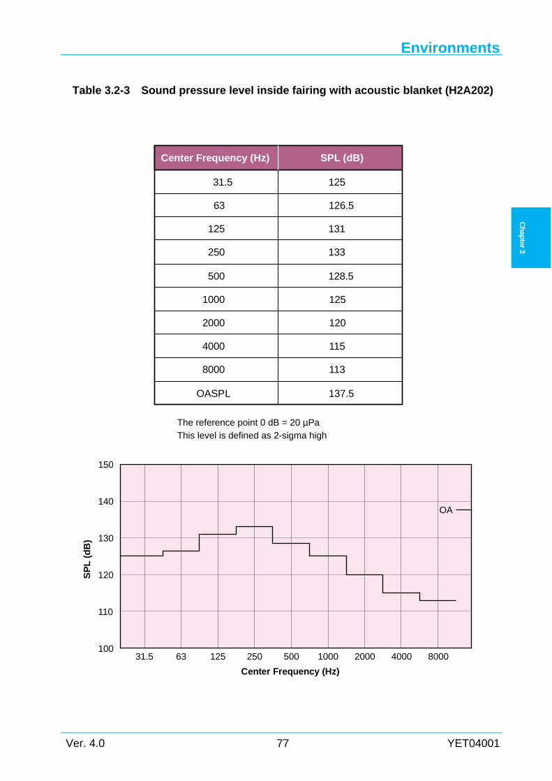
Environments
Ver. 4.0 77 YET04001
Ch
apter 3
Table 3.2-3 Sound pressure level inside fairing with acoustic blanket (H2A202)
The reference point 0 dB = 20 µPa This level is defined as 2-sigma high
Center Frequency (Hz) SPL (dB)
31.5
63
125
250
500
1000
2000
4000
8000
OASPL
125
126.5
131
133
128.5
125
120
115
113
137.5
150
140
130
120
110
100
SP
L (
dB
)
31.5 63 125 250 500 1000 2000 4000 8000
Center Frequency (Hz)
OA
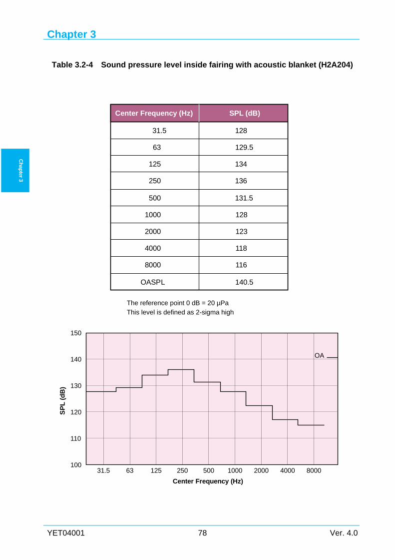
Chapter 3
YET04001 78 Ver. 4.0
Ch
apter 3
Table 3.2-4 Sound pressure level inside fairing with acoustic blanket (H2A204)
The reference point 0 dB = 20 µPa This level is defined as 2-sigma high
Center Frequency (Hz) SPL (dB)
31.5
63
125
250
500
1000
2000
4000
8000
OASPL
128
129.5
134
136
131.5
128
123
118
116
140.5
150
140
130
120
110
100
SP
L (
dB
)
31.5 63 125 250 500 1000 2000 4000 8000
Center Frequency (Hz)
OA
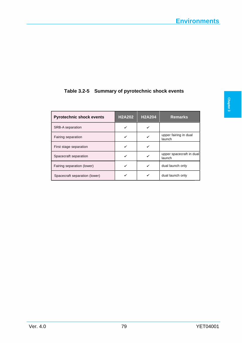
Environments
Ver. 4.0 79 YET04001
Ch
apter 3
Table 3.2-5 Summary of pyrotechnic shock events
Pyrotechnic shock events H2A202 H2A204 Remarks
SRB-A separation
Fairing separation
Fairing separation (lower)
First stage separation
upper fairing in duallaunch
upper spacecraft in duallaunch
dual launch only
dual launch only
Spacecraft separation
Spacecraft separation (lower)
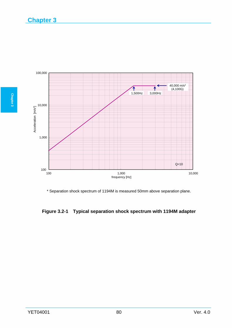
Chapter 3
YET04001 80 Ver. 4.0
Ch
apter 3
* Separation shock spectrum of 1194M is measured 50mm above separation plane.
Figure 3.2-1 Typical separation shock spectrum with 1194M adapter
100
1,000
10,000
100,000
100 1,000 10,000
Acc
ele
ratio
n[m
/s2]
frequency [Hz]
40,000 m/s2
(4,100G)1,500Hz 3,000Hz
Q=10
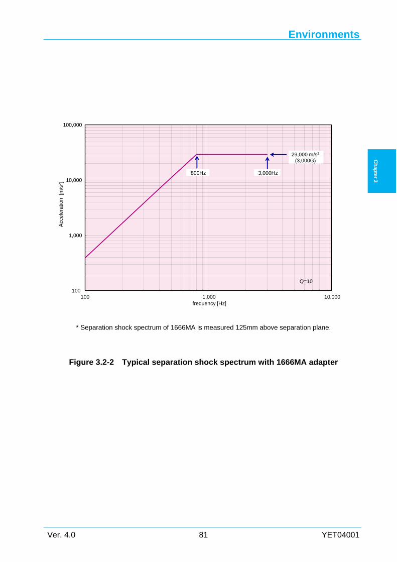
Environments
Ver. 4.0 81 YET04001
Ch
apter 3
* Separation shock spectrum of 1666MA is measured 125mm above separation plane.
Figure 3.2-2 Typical separation shock spectrum with 1666MA adapter
100
1,000
10,000
100,000
100 1,000 10,000
Acc
ele
ratio
n[m
/s2]
frequency [Hz]
29,000 m/s2
(3,000G)
800Hz 3,000Hz
Q=10
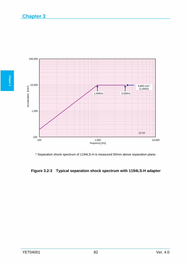
Chapter 3
YET04001 82 Ver. 4.0
Ch
apter 3
* Separation shock spectrum of 1194LS-H is measured 50mm above separation plane.
Figure 3.2-3 Typical separation shock spectrum with 1194LS-H adapter
100
1,000
10,000
100,000
100 1,000 10,000
Acc
ele
ratio
n[m
/s2]
frequency [Hz]
9,800 m/s2
(1,000G)
1,000Hz 3,000Hz
Q=10
Environments
Ver. 4.0 83 YET04001
Ch
apter 3
Thermal Environments 3.3
3.3.1 General Concerning thermal environments, following four phases have to be considered:
(1) the phase of spacecraft preparation in the Ground Support Equipment (GSE) buildings
and transport between these buildings (Refer to the GSE Manual for details)
(2) the phase of spacecraft encapsulation into the payload fairing and mounting on the
launch vehicle in the Vehicle Assembly Building (VAB).
(3) the phase of ML roll-out to the launch pad and the final prelaunch
(4) the in-flight phase
The phases from (1) to (3) are concerned with prelaunch environment and (4) are concerned
with launch and flight environments.
3.3.2 Prelaunch environment The spacecraft thermal environment is controlled during prelaunch activities such as
spacecraft integration, functional test, propellant loading, mating to the payload adapter (PLA),
encapsulation in the fairing, mounting on the launch vehicle, final checkout, ML roll-out to the
launch pad, etc.
Environments during these activities are shown in Table 3.3-1.
From ML roll-out until liftoff, fairing temperature is controlled by the state of fairing inlet, not
inside the fairing, and the air dryer removes moisture from compressed air with a dew point as
low as 0 ºC. If needed, fairing inlet temperature is adjustable by spacecraft temperature condition,
Contact LSP for details.
3.3.3 Launch and flight environments (1) Inside fairing (from liftoff to fairing separation)
The spacecraft is protected by the payload fairing during ascent to a nominal altitude of
approximately 130 km (430 kft). But aerodynamic heating heats the fairing surface and the
spacecraft receives a time-dependent radiant heating environment from the internal surface of
this fairing prior to fairing separation.
Figure 3.3-1 and Figure3.3-2 show typical internal surface temperature profiles of the Model
4S fairing or Model 4/4D upper fairing for H2A202 and H2A204 mission. And Figure 3.3-3
shows typical internal surface temperature profiles of the Model 5S fairing for a H2A202
mission. Further, Table 3.3-2 shows the maximum temperature and total hemispherical emittance
of internal surfaces of the payload fairing during ascent flight. The maximum heat flux of
H2A202 is less than 500 W/m2, and that of H2A204 is less than 600 W/m2.
Figure 3.3-1, Figure3.3-2, Figure 3.3-3, and Table 3.3-2 are reference.
(2) After fairing separation
The nominal timing for fairing separation on all flights is determined so that the maximum
Chapter 3
YET04001 84 Ver. 4.0
Ch
apter 3
free molecular heat flux does not exceed 1135 W/m2. Typical free molecular heating profile for
GTO mission is shown in Figure 3.3-4 as reference. This heat flux is evaluated as a free
molecular flow acting on a plane surface perpendicular to the velocity vector and is based on a
standard atmospheric model. The spacecraft thermal environment after fairing separation
includes free molecular heating, solar radiation, earth radiation, earth albedo, radiation to the
second stage and deep space and thermal flux conducted from the forward end of the second
stage through the spacecraft adapter. Solar and earth thermal radiation can be controlled as
required by the spacecraft by selecting launch time, vehicle attitude (including rolls) and proper
mission design. Thermal heat conducted from the second stage, and influence of RCS plumes
and expelled LH2 / GH2 and LOX / GOX are usually small. These values are estimated in the
mission analysis.
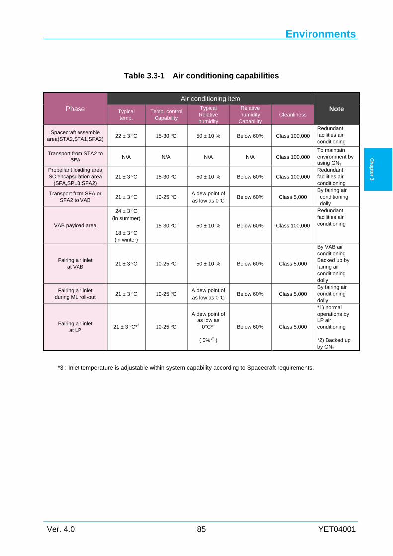
Environments
Ver. 4.0 85 YET04001
Ch
apter 3
Table 3.3-1 Air conditioning capabilities
Phase
Air conditioning item Note Typical
temp. Temp. control
Capability
Typical Relative humidity
Relative humidity
Capability Cleanliness
Spacecraft assemble area(STA2,STA1,SFA2)
22 ± 3 ºC 15-30 ºC 50 ± 10 % Below 60% Class 100,000
Redundant facilities air conditioning
Transport from STA2 to SFA
N/A N/A N/A N/A Class 100,000 To maintain environment by using GN2
Propellant loading area SC encapsulation area
(SFA,SPLB,SFA2) 21 ± 3 ºC 15-30 ºC 50 ± 10 % Below 60% Class 100,000
Redundant facilities air conditioning
Transport from SFA or SFA2 to VAB
21 ± 3 ºC 10-25 ºC A dew point of as low as 0°C
Below 60% Class 5,000 By fairing air conditioning dolly
VAB payload area
24 ± 3 ºC (in summer)
18 ± 3 ºC (in winter)
15-30 ºC 50 ± 10 % Below 60% Class 100,000
Redundant facilities air conditioning
Fairing air inlet at VAB
21 ± 3 ºC 10-25 ºC 50 ± 10 % Below 60% Class 5,000
By VAB air conditioning Backed up by fairing air conditioning dolly
Fairing air inlet during ML roll-out
21 ± 3 ºC 10-25 ºC A dew point of as low as 0°C
Below 60% Class 5,000 By fairing air conditioning dolly
Fairing air inlet at LP
21 ± 3 ºC*3 10-25 ºC
A dew point of as low as
0°C*1
( 0%*2 )
Below 60% Class 5,000
*1) normal operations by LP air conditioning *2) Backed up by GN2
*3 : Inlet temperature is adjustable within system capability according to Spacecraft requirements.
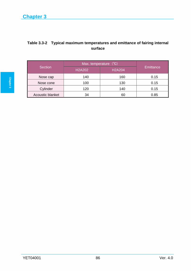
Chapter 3
YET04001 86 Ver. 4.0
Ch
apter 3
Table 3.3-2 Typical maximum temperatures and emittance of fairing internal
surface
Section Max. temperature ()
Emittance H2A202 H2A204
Nose cap 140 160 0.15
Nose cone 100 130 0.15
Cylinder 120 140 0.15
Acoustic blanket 34 60 0.85
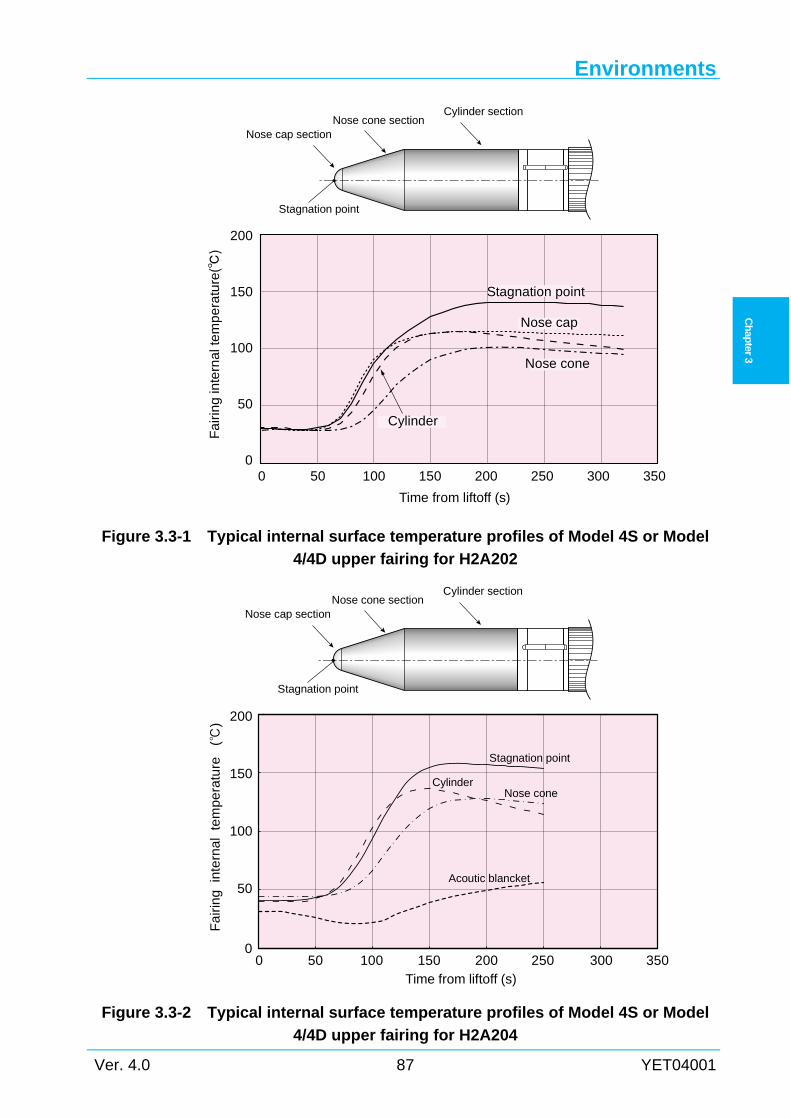
Environments
Ver. 4.0 87 YET04001
Ch
apter 3
Stagnation point
Nose cap section
Cylinder sectionNose cone section
0 50 100 150 200 250 300 3500
50
100
150
200
Nose cap
Cylinder
Nose cone
Fa
irin
g in
tern
al t
em
pe
ratu
re
Time from liftoff (s)
Stagnation point
Stagnation point
Nose cap section
Cylinder sectionNose cone section
Fa
irin
gin
tern
al
tem
pe
ratu
re
()
Time from liftoff (s)
Stagnation point
CylinderNose cone
Acoutic blancket
0
50
100
150
200
0 50 100 150 200 250 300 350
Figure 3.3-1 Typical internal surface temperature profiles of Model 4S or Model
4/4D upper fairing for H2A202
Figure 3.3-2 Typical internal surface temperature profiles of Model 4S or Model
4/4D upper fairing for H2A204
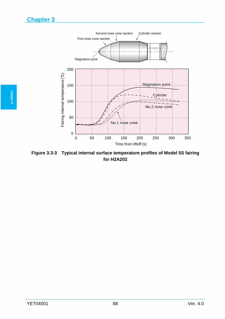
Chapter 3
YET04001 88 Ver. 4.0
Ch
apter 3
Figure 3.3-3 Typical internal surface temperature profiles of Model 5S fairing
for H2A202
0 50 100 150 200 250 300 3500
50
100
150
200
Stagnation point
No.1 nose cone
No.2 nose cone
Cylinder
Fa
irin
g in
tern
al t
em
pe
ratu
re
Time from liftoff (s)
Stagnation point
First nose cone section
Second nose cone section Cylinder section
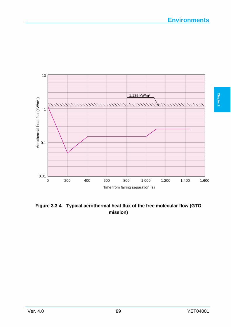
Environments
Ver. 4.0 89 YET04001
Ch
apter 3
Figure 3.3-4 Typical aerothermal heat flux of the free molecular flow (GTO
mission)
10
0 200 400 600 800 1,000 1,200 1,400 1,600
Time from fairing separation (s)
1
0.1
0.01
Ae
roth
erm
al h
ea
t flu
x (k
W/m
2) 1.135 kW/m²
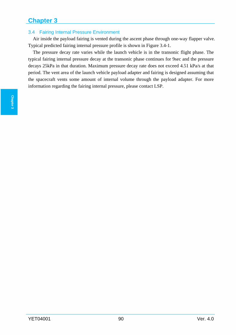
Chapter 3
YET04001 90 Ver. 4.0
Ch
apter 3
Fairing Internal Pressure Environment 3.4Air inside the payload fairing is vented during the ascent phase through one-way flapper valve.
Typical predicted fairing internal pressure profile is shown in Figure 3.4-1.
The pressure decay rate varies while the launch vehicle is in the transonic flight phase. The
typical fairing internal pressure decay at the transonic phase continues for 9sec and the pressure
decays 25kPa in that duration. Maximum pressure decay rate does not exceed 4.51 kPa/s at that
period. The vent area of the launch vehicle payload adapter and fairing is designed assuming that
the spacecraft vents some amount of internal volume through the payload adapter. For more
information regarding the fairing internal pressure, please contact LSP.
Environments
Ver. 4.0 91 YET04001
Ch
apter 3
Figure 3.4-1 Typical fairing internal pressure profile
0
20
40
60
80
100
120
0 10 20 30 40 50 60 70 80 90 100
Fai
rin
gin
tern
al p
ress
ure
(kP
a)
Time from liftoff (s)
Chapter 3
YET04001 92 Ver. 4.0
Ch
apter 3
Contamination and Cleanliness 3.5
3.5.1 Prelaunch contamination and cleanliness The launch vehicle hardware which may affect the spacecraft environment is designed,
manufactured and handled according to strict contamination control guidelines. This hardware is
defined as a contamination critical item, and includes the payload support structure, the payload
adapter and the interior surface of the payload fairing. Air supplied to the spacecraft is also
controlled strictly according to the contamination control guidelines.
(1) Contamination control before spacecraft encapsulation
All spacecraft processing area is cleaned up before spacecraft arrival. Before spacecraft
encapsulation, the faring, PSS, and PLA inner surfaces are cleaned up and verified with the level
"VC+UV"(Visibly Clean Plus Ultraviolet). The surface particle count is performed and particle
cleanliness level is recorded to maintain cleanliness. Air is also controlled at less than Class
100,000 conditions through the HEPA filter.
(2) Contamination control after encapsulation
After the spacecraft is encapsulated in the fairing, the payload compartment inside the fairing
is completely closed except access doors or large doors. Air controlled at less than Class 5,000
conditions is supplied through the air conditioning duct and maintained in higher pressure
condition than around the fairing.
(3) NVR
NVR cumulative rate does not exceed 0.1mg/m2 per day in any spacecraft processing area.
3.5.2 Flight contamination control (1) CCAM
The sequence of the spacecraft separation and the collision / contamination avoidance
maneuver is carried out as described in Section 2.7.2. In this phase, the RCS is used for attitude
control and propellant settling (if required, used as retro-motors to move the vehicle away from
the spacecraft after separation). As part of the maneuver, GH2 is expelled from the LH2 tank
through the propulsive vent port to increase second stage / spacecraft separation distance. Further,
for safety disposal of the second stage, LH2 and LOX are expelled from each tank through each
engine chill down port which is non-propulsive, GOX is expelled from the LOX tank through the
vent port (non-propulsive), GH2 is expelled from the LH2 tank through the non-propulsive or
propulsive vent port, and cryogenic GHe is also discharged from GHe bottles through the LOX
tank.
The installation location and cant angle of RCS thrusters, vent ports and chill down ports are
roughly shown in Table 3.5-1. The RCS is of a module type and two RCS modules are installed
on the component equipment panel located at the aft end of the second stage LOX tank and are
located in vehicle axis symmetry. One RCS module consists of four 50 N hydrazine (N2H4)
Environments
Ver. 4.0 93 YET04001
Ch
apter 3
thrusters. (If required, six more 50 N thrusters and one 4 N thruster are added per module.) The
thruster’s exhaust gas is mainly composed of ammonia, nitrogen and hydrogen. Use of RCS
thrusters is restricted to minimize contamination products.
The expelled products from each vent and chill down port are hydrogen, oxygen and a small
amount of helium which are almost non-contaminating to the spacecraft.
(2) Outgassing
Non-metallic materials inside the fairing when exposed to a vacuum environment do not
exceed the following values defined in ASTM E595.
(a) Total mass loss (%TML) :Less than 1.0%.
(b) Collected volatile condensable materials (%CVCM) :Less than 0.1%.
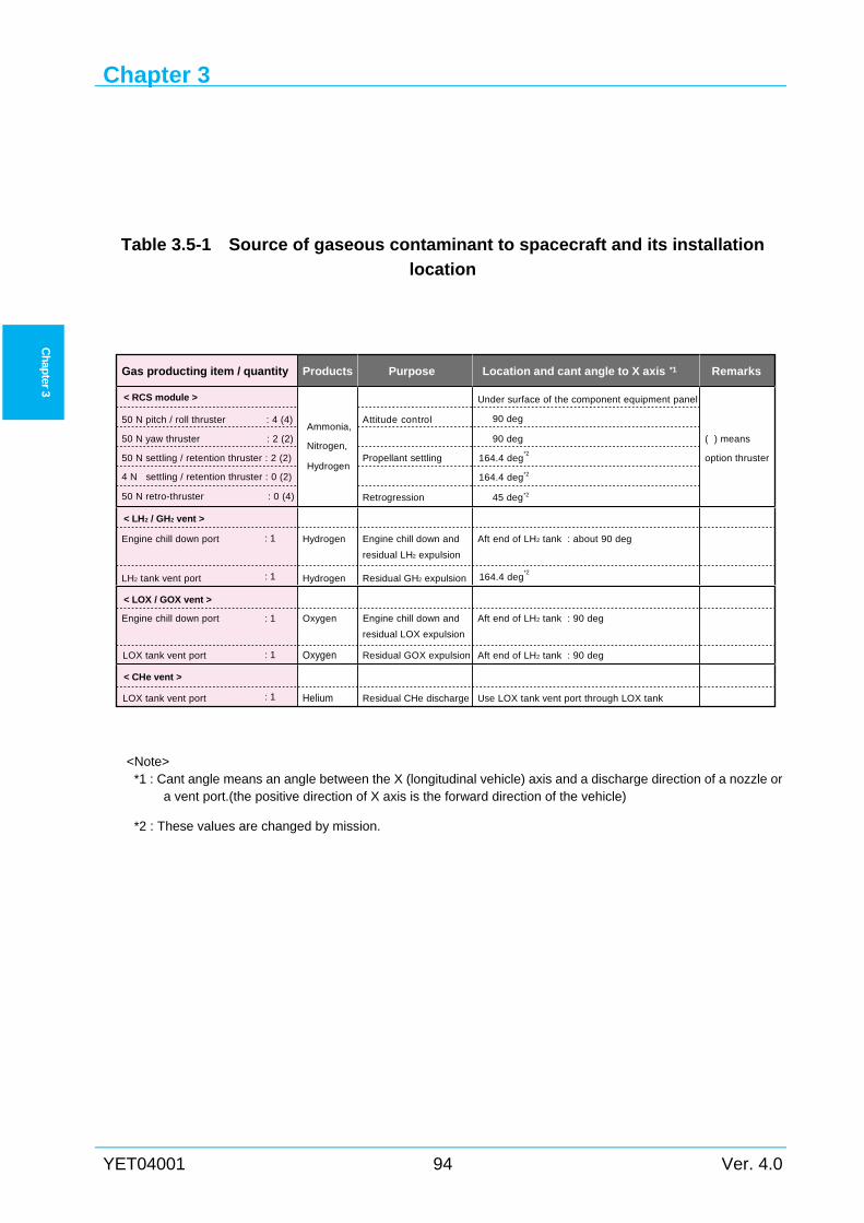
Chapter 3
YET04001 94 Ver. 4.0
Ch
apter 3
Table 3.5-1 Source of gaseous contaminant to spacecraft and its installation
location
<Note>
*1 : Cant angle means an angle between the X (longitudinal vehicle) axis and a discharge direction of a nozzle or a vent port.(the positive direction of X axis is the forward direction of the vehicle)
*2 : These values are changed by mission.
Gas producting item / quantity Products Purpose Location and cant angle to X axis *1 Remarks
< RCS module >
50 N pitch / roll thruster : 4 (4)
50 N yaw thruster : 2 (2)
50 N settling / retention thruster : 2 (2)
4 N settling / retention thruster : 0 (2)
50 N retro-thruster : 0 (4)
Ammonia,
Nitrogen,
Hydrogen
Attitude control
Propellant settling
Retrogression
Under surface of the component equipment panel
90 deg
90 deg
164.4 deg
164.4 deg
45 deg
( ) means
option thruster
< LH2 / GH2 vent >
Engine chill down port
LH2 tank vent port
Hydrogen
Hydrogen
Engine chill down and
residual LH2 expulsion
Residual GH2 expulsion
Aft end of LH2 tank : about 90 deg
< LOX / GOX vent >
Engine chill down port
LOX tank vent port
Oxygen
Oxygen Residual GOX expulsion
Aft end of LH2 tank : 90 deg
Aft end of LH2 tank : 90 deg
< CHe vent >
LOX tank vent port Helium Residual CHe discharge Use LOX tank vent port through LOX tank
: 1
: 1
: 1
: 1
: 1
residual LOX expulsion
Engine chill down and
*2
*2
*2
164.4 deg*2
Environments
Ver. 4.0 95 YET04001
Ch
apter 3
Radiation and Electromagnetic Environments 3.6
3.6.1 General To ensure that electromagnetic compatibility (EMC) is achieved for each launch, the
electromagnetic environment is thoroughly evaluated. The spacecraft and the launch vehicle
system should prevent mutual disturbance for devices and wiring of each system, and be
designed to endure any anticipated disturbance. The spacecraft system will be required to
provide all data necessary to support EMC analysis employed for this purpose.
3.6.2 H-IIA radio environment Radio environment generated by H-IIA launch vehicle on-board RF equipment, TNSC
facilities, and nearby facilities are shown in Figure 3.6-1 and Figure 3.6-2. For “Hot launch”
spacecraft, SCO should satisfy the following requirements.
(1) Spurious emission level from the launch vehicle and ground facilities is shown in
Figure 3.6-1. The spacecraft's spurious susceptibility level should satisfy the spurious
emission level in Figure 3.6-1.
(2) The spacecraft should not radiate exceeding the “H-IIA spurious susceptibility level”
as the worst case of the sum spurious level shown in Figure 3.6-2.
(3) The spurious emission level and susceptibility level are defined at the spacecraft
separation plane.
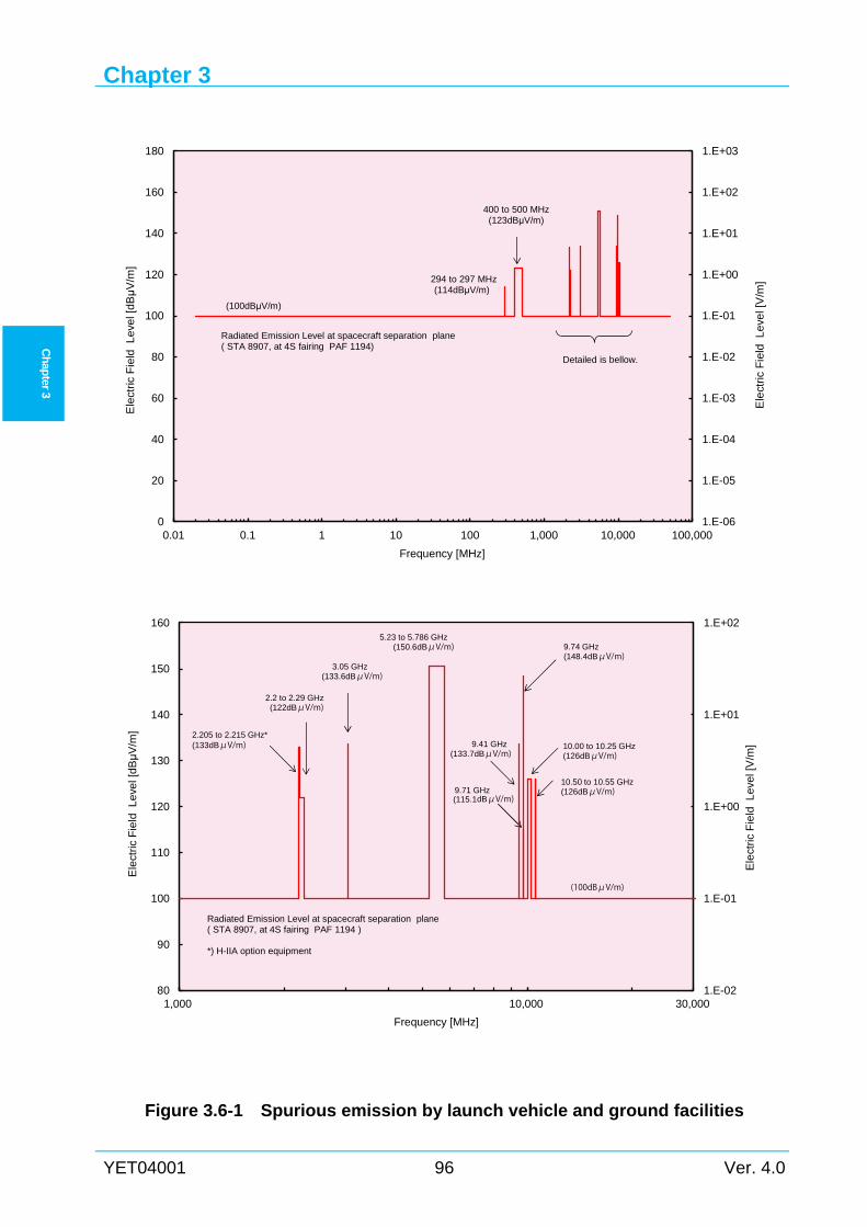
Chapter 3
YET04001 96 Ver. 4.0
Ch
apter 3
Figure 3.6-1 Spurious emission by launch vehicle and ground facilities
1.E-06
1.E-05
1.E-04
1.E-03
1.E-02
1.E-01
1.E+00
1.E+01
1.E+02
1.E+03
0
20
40
60
80
100
120
140
160
180
0.01 0.1 1 10 100 1,000 10,000 100,000
Ele
ctric
Fie
ldL
eve
l [V
/m]
Ele
ctric
Fie
ldL
eve
l [d
Bμ
V/m
]
Frequency [MHz]
(100dBμV/m)
294 to 297 MHz(114dBμV/m)
400 to 500 MHz(123dBμV/m)
Detailed is bellow.
Radiated Emission Level at spacecraft separation plane( STA 8907, at 4S fairing PAF 1194)
1.E-02
1.E-01
1.E+00
1.E+01
1.E+02
80
90
100
110
120
130
140
150
160
1,000 10,000 30,000
Ele
ctric
Fie
ldL
evel
[V/m
]
Ele
ctric
Fie
ldL
eve
l [dB
μV
/m]
Frequency [MHz]
2.2 to 2.29 GHz(122dBμV/m)
3.05 GHz(133.6dBμV/m)
5.23 to 5.786 GHz(150.6dBμV/m)
10.00 to 10.25 GHz(126dBμV/m)
9.41 GHz(133.7dBμV/m)
9.74 GHz(148.4dBμV/m)
2.205 to 2.215 GHz*(133dBμV/m)
10.50 to 10.55 GHz(126dBμV/m)
Radiated Emission Level at spacecraft separation plane( STA 8907, at 4S fairing PAF 1194 )
*) H-IIA option equipment
(100dBμV/m)
9.71 GHz(115.1dBμV/m)
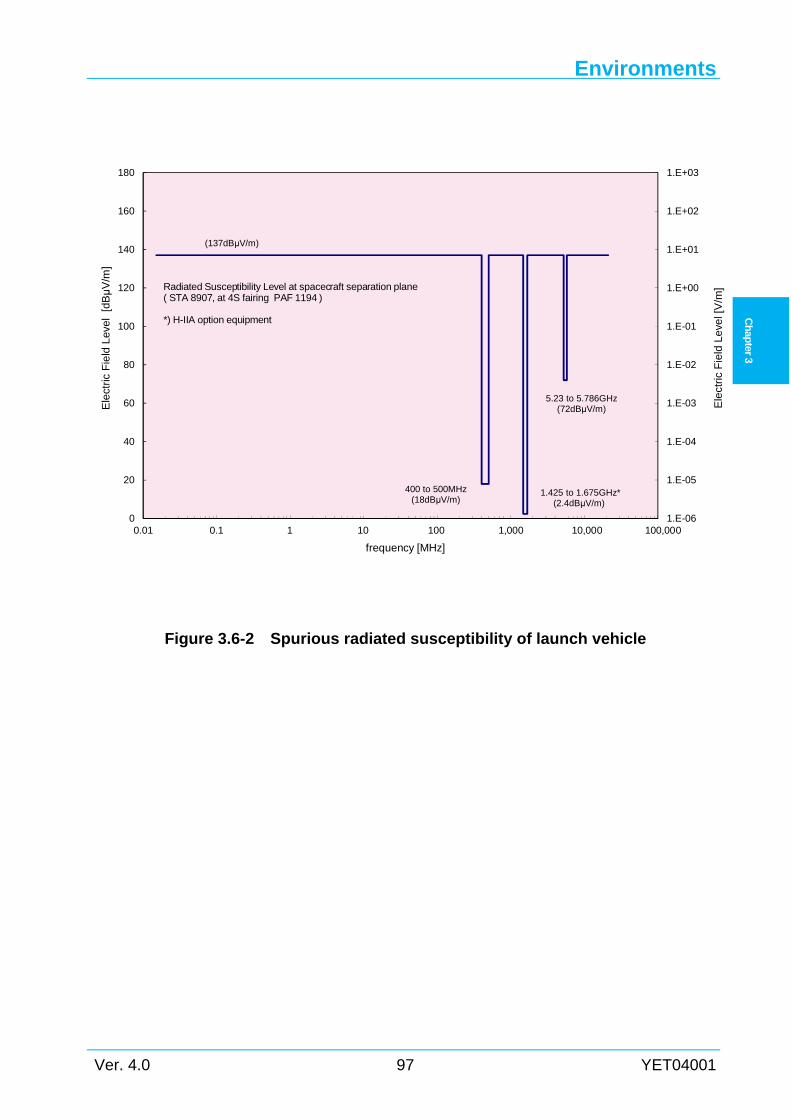
Environments
Ver. 4.0 97 YET04001
Ch
apter 3
Figure 3.6-2 Spurious radiated susceptibility of launch vehicle
1.E-06
1.E-05
1.E-04
1.E-03
1.E-02
1.E-01
1.E+00
1.E+01
1.E+02
1.E+03
0
20
40
60
80
100
120
140
160
180
0.01 0.1 1 10 100 1,000 10,000 100,000
Ele
ctric
Fie
ldL
evel
[dBμ
V/m
]
frequency [MHz]
Radiated Susceptibility Level at spacecraft separation plane( STA 8907, at 4S fairing PAF 1194 )
*) H-IIA option equipment
Ele
ctric
Fie
ldL
eve
l [V
/m]
5.23 to 5.786GHz(72dBμV/m)
1.425 to 1.675GHz*(2.4dBμV/m)
400 to 500MHz(18dBμV/m)
(137dBμV/m)
Chapter 3
YET04001 98 Ver. 4.0
Ch
apter 3
Spacecraft Compatibility Test Requirements 3.7LSP requires that the spacecraft be capable of withstanding maximum expected flight loads
multiplied by minimum factors of safety to preclude loss of critical function. An environmental
test report is required to summarize the performed tests and to document the adequacy of the
spacecraft structure for flight loads.
The spacecraft tests required for demonstration of compatibility are listed in Table 3.7-1. This
table describes tests, margins, and durations appropriate for recommendation in three phases of
development. The structural test model (STM) is considered a test-dedicated qualification article.
The proto-flight model (PFM) is the first flight article produced without a qualification or STM
program. The flight model (FM) is defined as a flight article produced after the qualification or
proto-flight article.
LSP also suggests that the spacecraft organization demonstrate the spacecraft compatibility to
thermal and EMI / EMC environments.
Flight hardware match mate tests are performed to verify mating interfaces and envelopes.
Table 3.7-2 identifies recommended spacecraft qualification and acceptance tests to validate
adequate compliance with H-IIA environments.
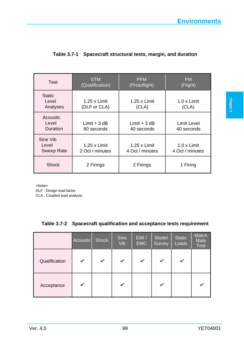
Environments
Ver. 4.0 99 YET04001
Ch
apter 3
Table 3.7-1 Spacecraft structural tests, margin, and duration
<Note> DLF : Design load factor CLA : Coupled load analysis
Table 3.7-2 Spacecraft qualification and acceptance tests requirement
Test
Shock
Static Level Analyses
1.25 x Limit(DLF or CLA)
Limit + 3 dB80 seconds
Limit + 3 dB40 seconds
Limit Level40 seconds
1.25 x Limit(CLA)
1.0 x Limit(CLA)
1.25 x Limit2 Oct / minutes
2 Firings 2 Firings 1 Firing
1.25 x Limit4 Oct / minutes
1.0 x Limit4 Oct / minutes
Acoustic Level Duration
Sine Vib Level Sweep Rate
STM(Qualification)
PFM(Protoflight)
FM(Flight)
Qualification
Acceptance
Acoustic Shock SineVib
EMI /EMC
ModelSurvey
StaticLoads
MatchMateTest
Chapter 3
YET04001 100 Ver. 4.0
Ch
apter 3
Intentionally blank
Chapter 4
Ver. 4.0 101 YET04001
Ch
apter 4
Chapter 4 SPACECRAFT INTERFACE
4.1 General This chapter describes interface requirements between the spacecraft and the H-IIA launch
vehicle. In this chapter, spacecraft stiffness, spacecraft balance, mechanical interface, electrical
and RF link interface are included. All interface information given is a baseline. For more
information regarding interface modifications or tailoring, please contact LSP.
4.2 Launch Vehicle Coordinate System Figure 4.2-1 shows the H-IIA launch vehicle coordinate system used in this document. The
H-IIA launch pad direction (axis-II direction) is 125deg(CW) from north.
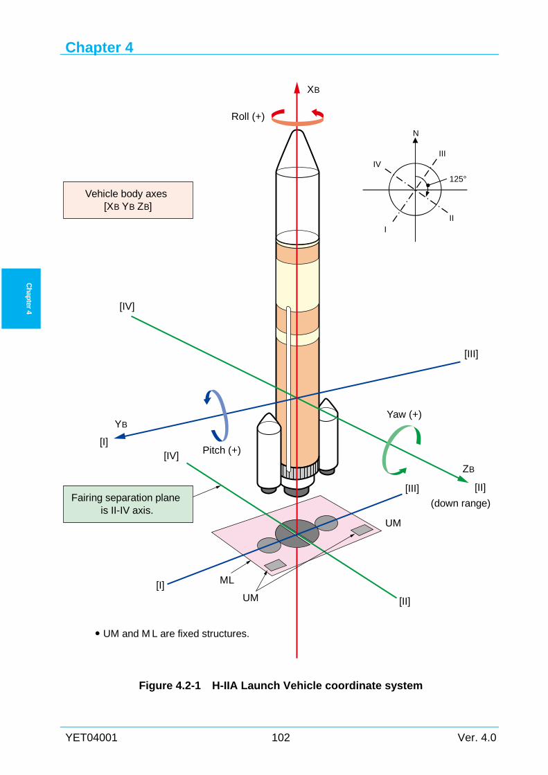
Chapter 4
YET04001 102 Ver. 4.0
Ch
apter 4
Figure 4.2-1 H-IIA Launch Vehicle coordinate system
Vehicle body axes[XB YB ZB]
Fairing separation planeis II-IV axis.
YB
ZB
XB
[I]
[I]
[IV]
[IV] Pitch (+)
Yaw (+)
Roll (+)
ML
UM
UM
(down range)
[III]
[III]
[II]
[II]
UM and M L are fixed structures.
IV
I
III
N
II
125°
Spacecraft Interface
Ver. 4.0 103 YET04001
Ch
apter
4
4.3 Stiffness of spacecraft To avoid dynamic coupling modes in the low-frequency between the launch vehicle and the
spacecraft during the ascent phase, the spacecraft should be designed with a structural stiffness
which satisfies the fundamental frequency requirements.
Under the assumption that the spacecraft is connected rigidly to the separation plane, its
primary structure fundamental frequency should be as follows:
(1) Lateral direction ≥ 10 Hz
(2) Longitudinal direction ≥ 30 Hz
If the spacecraft does not satisfy above conditions, SCO should discuss loads, environmental
conditions and usable volume, etc., with LSP using a result of Coupled Loads Analysis (CLA) at
the technical interchange meetings, and confirm that there are no problems.
4.4 Balance
4.4.1 General This section describes balance requirements for the spacecraft design. These are related to the
payload adapter strength and the center of gravity (CG) of the spacecraft. The CG of the
spacecraft affects angular rates at the spacecraft separation and spin-up unbalance for the spin-up
spacecraft.
In this manual, the spacecraft CG height means a distance from the spacecraft separation plane
to the spacecraft CG.
4.4.2 Height limit of the center of gravity The height limit of the spacecraft CG is defined according to the strength requirement of each
payload adapter. Therefore the height limit of CG depends on the used adapter type. The
allowable range of the spacecraft CG height for each type of the payload adapter is described in
Appendix 4.
4.4.3 Balance requirements
4.4.3.1 Static balance The CG offset of the spacecraft in radial direction should be as follows:
(1) Separation without spin-up ( or low angular rates separation motion)
Less than 25 mm from the launch vehicle center axis in radial direction
(2) Separation with spin-up ( 5 rpm in roll axis)
Less than 25 mm from the launch vehicle center axis in radial direction
Chapter 4
YET04001 104 Ver. 4.0
Ch
apter 4
4.4.3.2 Dynamic balance For the spacecraft which requires spin-up, the angle between the principal roll inertia axis of
the spacecraft and the launch vehicle roll axis (or the spacecraft spin axis) should be less than 3°.
For more information regarding the separation with spin-up, please contact LSP.
4.5 Payload Fairing This section describes the H-IIA launch vehicle payload fairing, especially the configuration,
usable volume, and mission modification of fairings. The spacecraft is located on top of the
launch vehicle second stage with a payload adapter, and encapsulated within the payload fairing
for launch environment protection. For dual launch, the upper spacecraft is located on top of the
lower fairing using an adapter for the upper spacecraft.
4.5.1 Fairing types There are 3 standard payload fairing models.
(1) 4 m diameter dedicated launch model (Model 4S*)
(2) 5 m diameter dedicated launch model (Model 5S*)
(3) 4 m diameter dual launch model (Model 4/4D-LC*)
— upper : long type
— lower : clamshell type
* “4” indicates 4 m diameter, “5” indicates 5 m diameter.
”S” indicates single launch, “D” indicates dual launch.
Table 4.5-1 shows characteristics of payload fairings. Usable volumes of the following
payload fairings take into account dynamic displacement of spacecraft which satisfies frequency
requirements described in Section 4.3.
4.5.1.1 Model 4S This payload fairing is available for a dedicated launch of 3.7 m diameter spacecraft.
Figure 4.5-1 shows the Model 4S.
Figure 4.5-2 and Figure4.5-3 show the usable volume of the Model 4S fairing.
4.5.1.2 Model 5S This payload fairing is available for a dedicated launch of 4.6 m diameter spacecraft.
Figure 4.5-4 shows the Model 5S.
Figure 4.5-5 shows the usable volume of the Model 5S fairing.
4.5.1.3 Model 4/4D-LC This payload fairing is available for a dual launch of 3.7 m diameter spacecraft.
Figure 4.5-6 shows the Model 4/4D-LC.
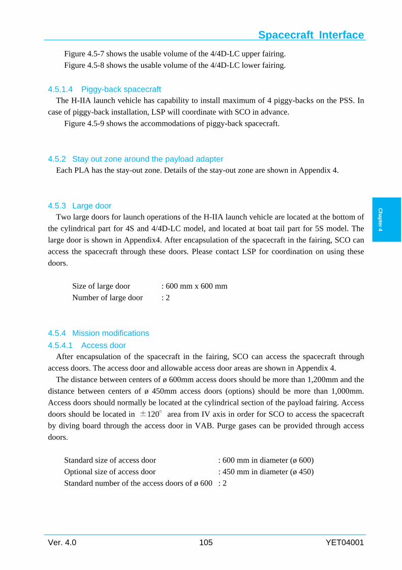
Spacecraft Interface
Ver. 4.0 105 YET04001
Ch
apter
4
Figure 4.5-7 shows the usable volume of the 4/4D-LC upper fairing.
Figure 4.5-8 shows the usable volume of the 4/4D-LC lower fairing.
4.5.1.4 Piggy-back spacecraft The H-IIA launch vehicle has capability to install maximum of 4 piggy-backs on the PSS. In
case of piggy-back installation, LSP will coordinate with SCO in advance.
Figure 4.5-9 shows the accommodations of piggy-back spacecraft.
4.5.2 Stay out zone around the payload adapter Each PLA has the stay-out zone. Details of the stay-out zone are shown in Appendix 4.
4.5.3 Large door Two large doors for launch operations of the H-IIA launch vehicle are located at the bottom of
the cylindrical part for 4S and 4/4D-LC model, and located at boat tail part for 5S model. The
large door is shown in Appendix4. After encapsulation of the spacecraft in the fairing, SCO can
access the spacecraft through these doors. Please contact LSP for coordination on using these
doors.
Size of large door : 600 mm x 600 mm
Number of large door : 2
4.5.4 Mission modifications
4.5.4.1 Access door After encapsulation of the spacecraft in the fairing, SCO can access the spacecraft through
access doors. The access door and allowable access door areas are shown in Appendix 4.
The distance between centers of ø 600mm access doors should be more than 1,200mm and the
distance between centers of ø 450mm access doors (options) should be more than 1,000mm.
Access doors should normally be located at the cylindrical section of the payload fairing. Access
doors should be located in ±120°area from IV axis in order for SCO to access the spacecraft
by diving board through the access door in VAB. Purge gases can be provided through access
doors.
Standard size of access door : 600 mm in diameter (ø 600)
Optional size of access door : 450 mm in diameter (ø 450)
Standard number of the access doors of ø 600 : 2
Chapter 4
YET04001 106 Ver. 4.0
Ch
apter 4
4.5.4.2 Umbilical connectors The umbilical connectors are mounted on the interface plane of the payload adapter. Details of
umbilical connectors are described in Section 4.7.6.
Standard number of umbilical connectors : 2
(Option)
If SCO requires, the lanyard umbilical connectors via payload fairing can be used. Details are
described in Section 4.7.6.5.
4.5.4.3 Radio transparent window After encapsulation of the spacecraft in the fairing, a radio transparent window is available to
link with the radio signals between the spacecraft and the spacecraft GSE. The radio transparent
window is shown in Appendix 4. It will be installed in the same area as the access door.
Material of radio transparent window : Glass fiber reinforced plastic
(GF skin honeycomb sandwich)
Size of radio transparent window : 450 mm diameter
Standard number of radio transparent windows : 1
(Option)
Instead of using a radio transparent window, an internal / external antenna connected through
a coaxial cable is available to link with the radio signals between the spacecraft and the
spacecraft GSE. It can receive and transmit radio signals before liftoff as a substitute for
transparent windows.
If SCO require RF link in flight, external antennas are available on outside of fairing as an
option.
4.5.4.4 Internal antenna After encapsulation of the spacecraft in the fairing, an internal antenna inside the fairing is
available to link with the radio signals between the spacecraft and the spacecraft GSE. It can
receive radio signals from the spacecraft and transmit radio signals from the spacecraft GSE.
Typical installation of an internal antenna is shown in Appendix 4. The internal antenna is
connected to Ground Support Equipment (GSE) through coaxial lines.
Standard number of internal antennas : 1
Spacecraft Interface
Ver. 4.0 107 YET04001
Ch
apter
4
4.5.4.5 Air conditioning After the spacecraft is encapsulated in the PLF, the conditioned air is supplied through the air
conditioning duct. In order to vent the air inside the PLF, Air inlet and vent valves (flapper
valves) are installed on the PLF. Ventilation airflow velocity near the spacecraft surface is not
exceed 2m/s. When fairing is used for dual launch, eight (8) vent holes are installed between the
upper and lower fairings.
Air flow rate : 50 m3/min each (dual)
: 100 m3/min (dedicated)
Size of air inlet : 400 mm diameter
Standard number of air inlet : 1 for Model 4S, 5S, 4/4D-LC upper and lower (each)
Number of flapper valves : 2 for Model 4S, 4/4D-LC upper and lower (each)
: 4 for Model 5S
4.5.4.6 Acoustic blankets Acoustic blankets are attached to the inner surface of the fairing to reduce acoustic sound
pressure level. Acoustic blankets are made of glass fiber and the cover material. Thickness and
size of blanket are determined according to SCO’s requirements. Typical configuration of an
acoustic blanket is shown in Appendix 4. The standard blanket is 10 mm thick.
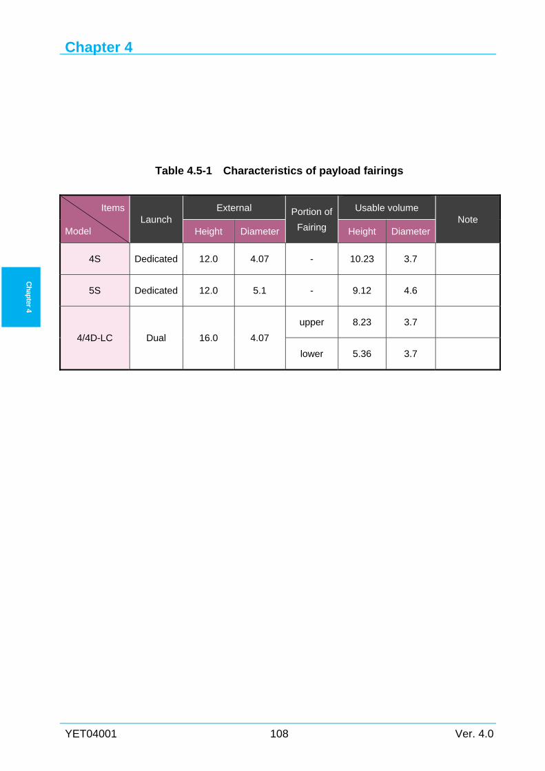
Chapter 4
YET04001 108 Ver. 4.0
Ch
apter 4
Table 4.5-1 Characteristics of payload fairings
Items
Model Launch
External Portion of
Fairing
Usable volume Note
Height Diameter Height Diameter
4S Dedicated 12.0 4.07 - 10.23 3.7
5S Dedicated 12.0 5.1 - 9.12 4.6
4/4D-LC Dual 16.0 4.07
upper 8.23 3.7
lower 5.36 3.7
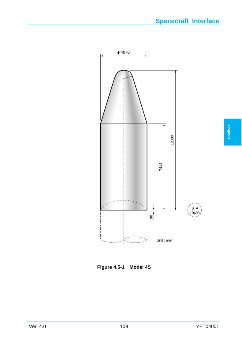
Spacecraft Interface
Ver. 4.0 109 YET04001
Ch
apter
4
Figure 4.5-1 Model 4S
ϕ 4070
STA10408
Unit : mm
90
7414
1200
0
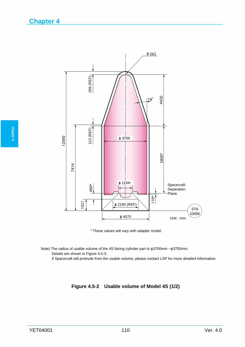
Chapter 4
YET04001 110 Ver. 4.0
Ch
apter 4
Note) The radius of usable volume of the 4S fairing cylinder part is φ3700mm ~φ3750mm. Details are shown in Figure 4.5-3. If Spacecraft will protrude from the usable volume, please contact LSP for more detailed information.
Figure 4.5-2 Usable volume of Model 4S (1/2)
R 565
18°
ϕ 2190 (REF)
ϕ 4070
ϕ 1194*
ϕ 3700
1200
0
7414
480 *
113
(RE
F)
5800
*
SpacecraftSeparationPlane
Unit : mm
110 *
269
(RE
F)
4430
* These values will vary with adapter model.
1021
STA10408
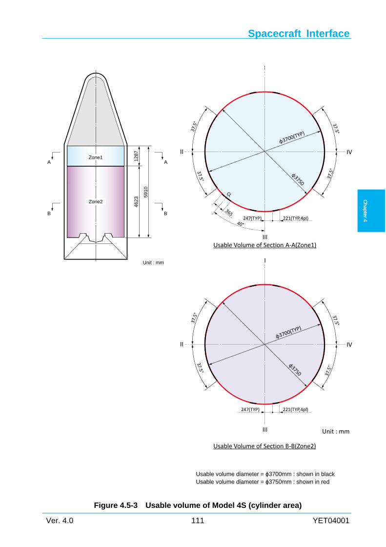
Spacecraft Interface
Ver. 4.0 111 YET04001
Ch
apter
4
Unit : mm
φ3700(T
YP)
φ3750
φ3700(T
YP)
φ3750
221(TYP,4pl)247(TYP)
221(TYP,4pl)247(TYP)
365
40°
CL37.5°
37.5°
37.5°
37.5°37.5°
37.5°37.5°
37.5°
I
II
III
IV
I
II
III
IV
Usable Volume of Section A‐A(Zone1)
Usable Volume of Section B‐B(Zone2)
Figure 4.5-3 Usable volume of Model 4S (cylinder area)
Unit : mm
591
0
Zone1 1287
AA
Zone2
4623
BB
Usable volume diameter = ϕ3700mm : shown in black Usable volume diameter = ϕ3750mm : shown in red
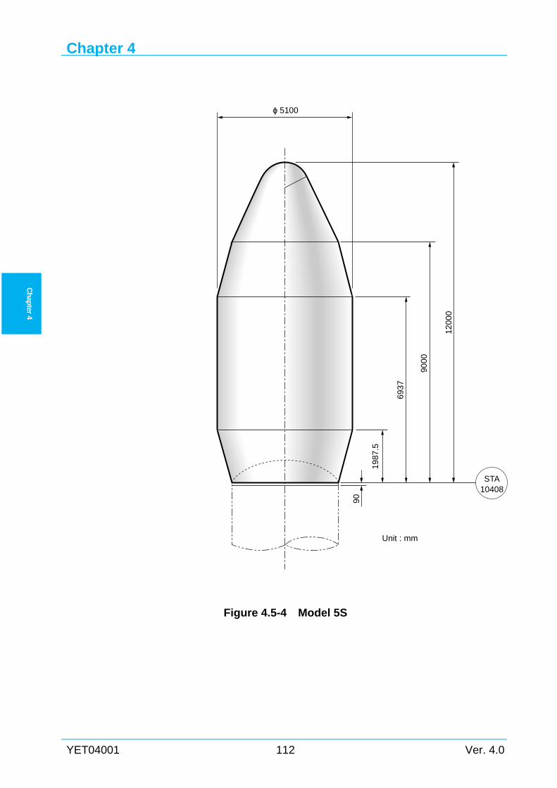
Chapter 4
YET04001 112 Ver. 4.0
Ch
apter 4
STA10408
ϕ 5100
1200
0
9000
693
7
1987
.5
Unit : mm
90
Figure 4.5-4 Model 5S
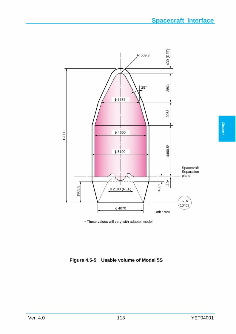
Spacecraft Interface
Ver. 4.0 113 YET04001
Ch
apter
4
Figure 4.5-5 Usable volume of Model 5S
R 509.3
ϕ 4070
ϕ 4600
1200
0
1965
.5
SpacecraftSeparationplane
480 *
ϕ 2190 (REF)
28°
430
(RE
F)
2601
2063
4460
.5*
Unit : mm
110 *
ϕ 3378
* These values will vary with adapter model.
ϕ 5100
STA10408
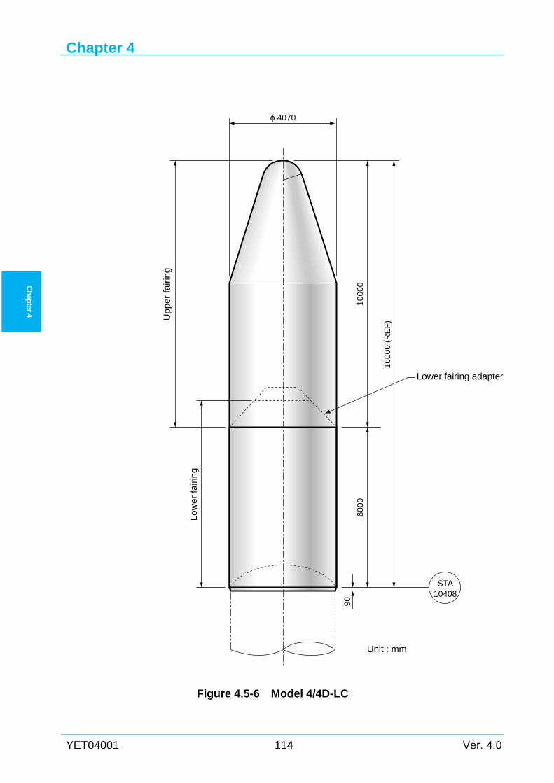
Chapter 4
YET04001 114 Ver. 4.0
Ch
apter 4
Figure 4.5-6 Model 4/4D-LC
ϕ 4070
1000
0
1600
0 (R
EF
)Lower fairing adapter
6000
Low
er fa
iring
Upp
er fa
iring
90
Unit : mm
STA10408
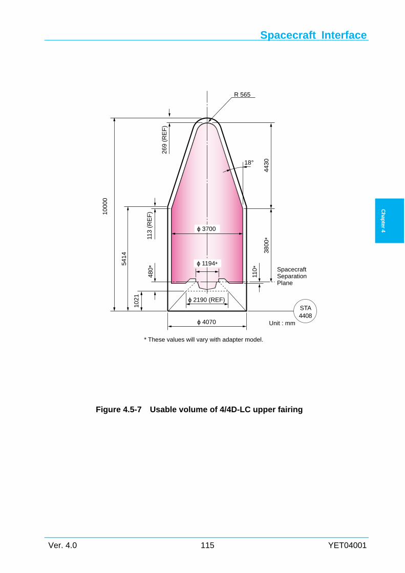
Spacecraft Interface
Ver. 4.0 115 YET04001
Ch
apter
4
Figure 4.5-7 Usable volume of 4/4D-LC upper fairing
R 565
18°
ϕ 4070
ϕ 1194*
ϕ 3700
1000
0
5414
1021
480
*
110
*
113
(RE
F)
3800
*SpacecraftSeparationPlane
Unit : mm
269
(RE
F)
* These values will vary with adapter model.
443
0
ϕ 2190 (REF)STA4408
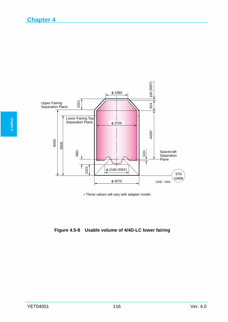
Chapter 4
YET04001 116 Ver. 4.0
Ch
apter 4
Figure 4.5-8 Usable volume of 4/4D-LC lower fairing
1021
6000
480 *
4436
*
ϕ 4070
924
5500
SpacecraftSeparationPlane
Unit : mm
* These values will vary with adapter model.
1021
ϕ 3700
110
*
ϕ 2190 (REF)
Lower Fairing TopSeparation Plane
160
(RE
F)
ϕ 1980
STA10408
Upper FairingSeparation Plane
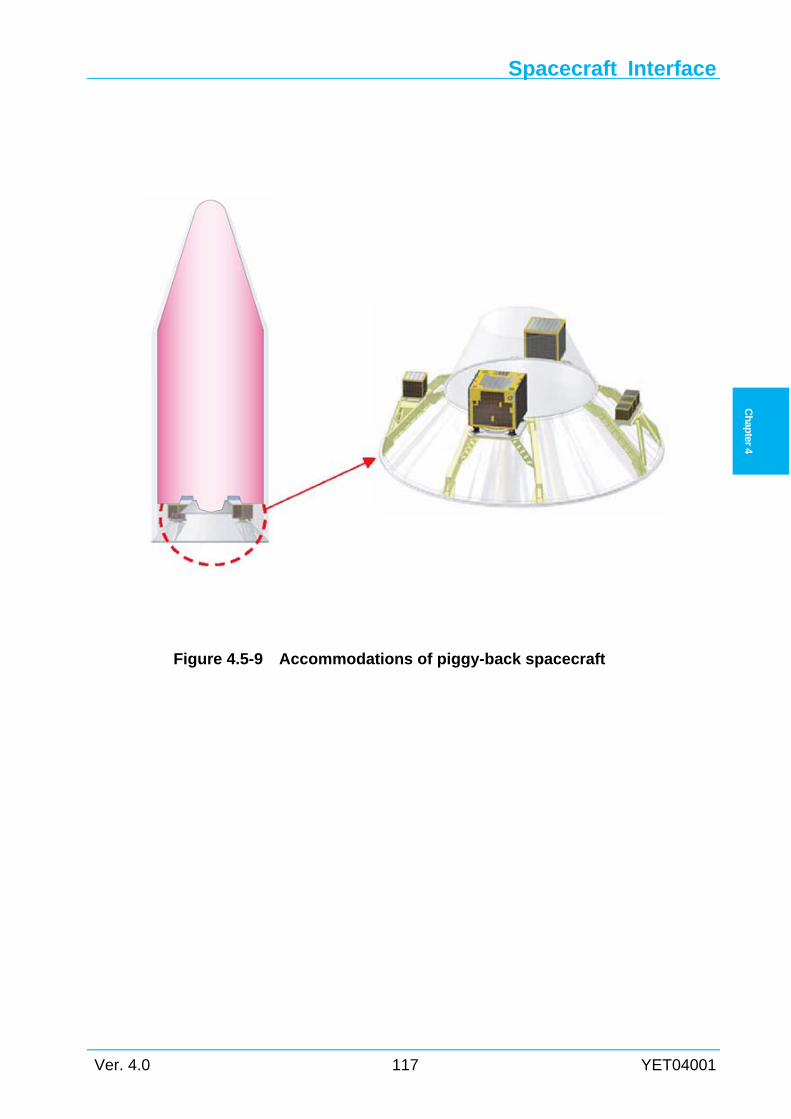
Spacecraft Interface
Ver. 4.0 117 YET04001
Ch
apter
4
Figure 4.5-9 Accommodations of piggy-back spacecraft
Chapter 4
YET04001 118 Ver. 4.0
Ch
apter 4
4.6 Payload Adapter
4.6.1 Adapter types Table 4.6-1 shows characteristics of the payload adapters for the H-IIA launch vehicle.
Detailed information related to the payload adapter is presented in Appendix 4.
(1) “1194” stands for that the interface diameter at the top of the adapter is 1194 mm.
(2) “M” stands for that the adapter has a clamp band separation mechanism.
(3) “LS-H” stands for that the adapter has a low shock clamp band mechanism.
If SCO desires another familiar adapter which is not listed in Table 4.6-1, LSP can procure
SCO requested adapter. Please contact LSP for details.
4.6.2 Mechanism of payload adapter The payload adapter mechanism is described below.
4.6.2.1 Separation mechanism The H-IIA launch vehicle provides clamp bands as the separation mechanism on the adapter.
The V flange of the rear frame of the spacecraft is connected to the top front of the adapter, and
bound by clamp bands with concave V shaped blocks. At the spacecraft separation, bolts which
connect the clamp bands are cut by pyrotechnic bolt cutters. For the low shock adapter, the
clamp bands are released by non-explosive or slow-released separation device. The clamp band
tension is designed to ensure no gaps exist between the spacecraft and the adapter frames on the
ground and in flight environments.
4.6.2.2 Ejection mechanism Separation springs are installed in the adapter to separate the spacecraft from the launch
vehicle. When the separation springs are installed, static loads act on each mating structure as
limit load, in addition to the acceleration load described in Section 3.2.1.
4.6.2.3 Spacecraft separation monitoring switches The standard launch vehicle has two (2) micro-switches on top of the adapter to monitor
spacecraft separation. It is possible to locate the actuator pad of the spacecraft micro-switch on
top of the adapter. In addition to the separation monitor switch, video camera is equipped on the
PSS below the payload adapter to ensure the monitor of the spacecraft separation. Video signals
are received on ground station. Spacecraft separation motion pictures are provided to SCO at
TNSC.
Spacecraft Interface
Ver. 4.0 119 YET04001
Ch
apter
4
4.6.3 Mission modifications
4.6.3.1 Separation springs Separation springs are installed inside the adapter to force the spacecraft away from the launch
vehicle.
a) Number of separation springs : 4 to 8
4.6.3.2 Umbilical connectors Umbilical connectors are installed on an adapter. Details are described in Section 4.7.6.
a) Number of umbilical connectors : 2
b) Location of umbilical connectors : Decided by discussion with SCO
c) Specification of umbilical connectors : Described in Section 4.7.6.4
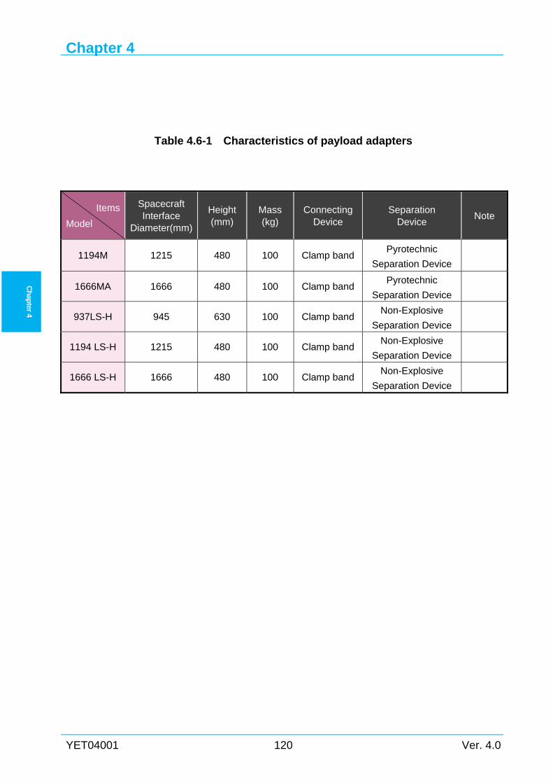
Chapter 4
YET04001 120 Ver. 4.0
Ch
apter 4
Table 4.6-1 Characteristics of payload adapters
Items
Model
Spacecraft Interface
Diameter(mm)
Height (mm)
Mass (kg)
Connecting Device
Separation Device
Note
1194M 1215 480 100 Clamp bandPyrotechnic
Separation Device
1666MA 1666 480 100 Clamp band Pyrotechnic
Separation Device
937LS-H 945 630 100 Clamp band Non-Explosive
Separation Device
1194 LS-H 1215 480 100 Clamp band Non-Explosive
Separation Device
1666 LS-H 1666 480 100 Clamp band Non-Explosive
Separation Device
Spacecraft Interface
Ver. 4.0 121 YET04001
Ch
apter
4
4.7 Electrical and RF Interfaces
4.7.1 General This section describes electrical interfaces such as electrical bonding, electrical command
interfaces from the launch vehicle; specifications of interface connector (umbilical connector);
and RF link between spacecraft and spacecraft GSE, etc.
4.7.2 Electrical bonding The spacecraft and launch vehicle must maintain the same electrical potential in flight, for
which bonding is necessary. Grounding (or earthing) is needed to ensure safety or protection of
electrical equipment and human by discharging the electrical energy to the earth on the ground.
LV provides the conductive path for grounding the SC.
The bonding which is the act of joining spacecraft and launch vehicle electrically is described
in this section. The bonding reference point should be located close to the separation plane of the
spacecraft and launch vehicle, where the bonding should be provided by mechanical contact of
both sides at connection. MIL-STD-464 class S (less than 1Ω) resistance requirement is applied
to the H-IIA launch vehicle bonding. Therefore, surface finish of the spacecraft separation
structure should satisfy the above requirement.
4.7.3 Command and power interfaces Table 4.7-1 shows the electrical interfaces which the H-IIA launch vehicle provides to the
spacecraft.
4.7.3.1 Pyrotechnic command The H-IIA launch vehicle can provide pyrotechnic commands to the spacecraft for the
following two functions:
(1) Spacecraft separation pyrotechnic command
When the spacecraft organization provides a separation mechanism, the launch vehicle system
can provide pyrotechnic commands for spacecraft separation. Details of design conditions, etc.,
are to be determined at the technical interchange meeting (TIM).
This command is provided as a standard service when the spacecraft organization provides a
separation mechanism.
(2) Other spacecraft related pyrotechnic commands
If the spacecraft system needs other commands, the launch vehicle system can provide
additional command as an option. The launch vehicle system can provide 10 command signals in
total including other pyrotechnic commands, electrical commands and dry loop commands for a
dual launch. For dual launch, the launch vehicle hardware spare channels are further limited, so
special arrangements must be made at the TIM.
Chapter 4
YET04001 122 Ver. 4.0
Ch
apter 4
Main electrical characteristics of the pyrotechnic command are the following and the wiring
diagram for the pyrotechnic command is shown in Figure 4.7-1.
(a) Source Battery
(b) Voltage 28 (+6, -4) VDC
(c) Ignition timing To be determined at the TIM
(d) Pulse width of igniting signal To be determined at the TIM
(e) Minimum igniting current To be determined at the TIM
(f) Recommended igniting current To be determined at the TIM
(g) Number of power cartridges To be determined at the TIM
(h) Non-igniting current To be determined at the TIM
(i) Bridge wire resistance To be determined at the TIM
(j) Insulation resistance To be determined at the TIM
(k) Insulation resistance after ignition To be determined at the TIM
4.7.3.2 Electrical command (discrete signal) (1) SCO can use electrical commands (discrete signals) from the launch vehicle, if necessary.
Total number of command signals is as described in Section 4.7.3.1. For a dual launch, if
both spacecraft require these signals, special arrangements must be made at the TIMs. These
commands are an optional service to the spacecraft.
(2) Launch vehicle wiring diagram for the electrical commands is shown in Figure 4.7-2.
(3) Main electrical characteristics of the electrical command are as follows,
(a) Voltage 28 (+6, -4) VDC
(b) Load resistance To be determined at the TIM
(c) Supply current To be determined at the TIM
(d) Insulation resistance To be determined at the TIM
(e) Supply timing To be determined at the TIM
(f) Supply time (duration) To be determined at the TIM
(g) Spacecraft circuit condition Insulated from ground and structure
Design details will be coordinated at the TIM.
4.7.3.3 Dry loop command (1) SCO can use dry loop commands from the launch vehicle, if necessary. Total number of
command signals is as described in Section 4.7.3.1. For dual launch, if both spacecraft
require these signals, special adjustment is required at the TIM. These commands are an
optional service to the spacecraft.
(2) Wiring diagram of the electrical commands is shown in Figure 4.7-3.
(3) Main electrical characteristics of the electrical command are as follows,
Spacecraft Interface
Ver. 4.0 123 YET04001
Ch
apter
4
(a) Supply timing/duration To be determined at the TIM
(b) Resistance (open/closed) To be determined at the TIM
(c) Voltage/Current(from spacecraft) To be determined at the TIM
(d) Insulation resistance To be determined at the TIM
Design details will be coordinated at the TIM.
4.7.3.4 Power supply If SCO requires external power supply, the launch vehicle can provide it to the extent which
depends on the mission. For more information regarding the in-flight power supply, please
contact LSP.
4.7.4 In-flight telemetry SCO can use the transmission of spacecraft measurement data by the L/V telemetry, if
necessary. For more information regarding the in-flight telemetry, please contact LSP.
4.7.5 Umbilical interface
4.7.5.1 Umbilical lines for dedicated launch mission The umbilical interface block diagram between the spacecraft and the ground facilities for a
dedicated launch is shown in Figure 4.7-4.
Spacecraft is connected to spacecraft GSE at ML GSE room through payload adapter, payload
fairing, umbilical, umbilical mast by copper lines. These hard lines are available for electrical
power supply, monitoring spacecraft system, telemetry transmission and command receipt. ML
GSE room and STA2/SFA2 are connected by 100Mbps single-mode fiber lines and 10/100Mbps
copper lines. These umbilical facilities make it possible to remote-control and tele-communicate
the spacecraft from STA2/SFA2 during prelaunch and launch countdown operations.
The interface connectors with the spacecraft are DBAS connectors. The interface connectors
at ML GSE room are shown in Table 4.7-2. The specifications for interface connectors with the
spacecraft (the spacecraft umbilical connector) are defined in the Interface Control Document
(ICD) for spacecraft. The maximum number of connector pins is 120.
4.7.5.2 Umbilical lines for dual launch mission The umbilical interface block diagram between the spacecraft and the ground facilities for a
dual launch is shown in Figure 4.7-5.
The specifications of interface connectors for the spacecraft in the upper fairing and lower
fairing are same for a dedicated launch mission in Section 4.7.5.1.
4.7.5.3 Spacecraft validation test configuration The spacecraft validation test configuration is shown in Figure 4.7-6. Typically, SCO is
Chapter 4
YET04001 124 Ver. 4.0
Ch
apter 4
allowed to check out the propellant loaded spacecraft from the remote building. The copper lines
between spacecraft and GSE are prepared by SCO. The copper lines can be used for both
Spacecraft/PLA composite configuration and Spacecraft/PLA/PSS composite configuration.
4.7.6 Interface connectors between spacecraft and launch vehicle This section specifies the interface connectors between the spacecraft and the H-IIA launch
vehicle.
LSP will use the DBAS connector as a standard connector shown in Section 4.7.6.4. If SCO
desires to use other interface connectors or interface connectors via payload fairing, please
contact LSP.
4.7.6.1 Interface connector procurement responsibility Interface connector receptacles (the spacecraft umbilical connectors) which are installed on
the spacecraft will be prepared by SCO and plugs will be prepared by LSP, respectively.
However, connector procurement responsibility can be arranged per SCO’s request.
4.7.6.2 Interface connectors for dedicated launch 2 interface connectors are used for electrical signals and electrical power supply of the
spacecraft. Interface connectors of launch vehicle are installed on the payload adapter. Interface
connectors via payload fairing are option.
LSP can install dry loop in the spacecraft connectors and fairing connectors. SCO can use dry
loop for additional sensing device of spacecraft separation, fairing separation. For more
information regarding the connectors specifications, please contact LSP.
Figure 4.7-7 shows interface connectors for a dedicated launch.
4.7.6.3 Interface connectors for dual launch Interface connectors for a dual launch will be the same as dedicated launch for the upper
spacecraft. Interface connectors via payload fairing are limited for upper spacecraft, and not used
for the lower spacecraft.
Figure 4.7-8 and Figure 4.7-9 show interface connectors for a dual launch.
4.7.6.4 Standard interface connector specifications The standard interface connector specifications should conform to the requirements of ESA/
ESCC SPEC. No. 3401/008, contacts SPEC. No. 3401/009. These connectors are manufactured
by TE Connectivity (DEUTSCH).
4.7.6.5 Other interface connector characteristics (1) Standard interface connector via PLA
2 interface connectors are located 180° opposite to each other on the PLA. The receptacle
surface should face the separation plane. The key position of interface connectors is set toward
Spacecraft Interface
Ver. 4.0 125 YET04001
Ch
apter
4
the external radial direction of the H-IIA launch vehicle.
(2) Interface connector via payload fairing (Option)
(a) Disconnecting angle of the plugs: The disconnecting angle of the H-IIA launch vehicle
plugs with lanyard shall be within ±10° at separation from spacecraft receptacles.
(b) Location: The interface connectors shall normally be placed within ±5° from the axis III
or I.
(c) Angle: The connectors shall be arranged within ±2° between the connector face and the
axis II - IV of the H-IIA launch vehicle.
(d) Pulling direction: Nothing shall be located within ±15° of the pulling direction.
(e) Key position: The key position of interface connectors is set upward direction of the
H-IIA launch vehicle.
If SCO requires the interface connectors via payload fairing, please contact LSP.
4.7.7 RF Link Interface
4.7.7.1 General LSP will provide the RF link system for S-band, C-band, X-band, and Ku-band telemetry/
command between the spacecraft on the H-IIA launch vehicle and SCO's GSE. The interface
conditions are defined as follows:
(1) Link path
(a) Between LP and Spacecraft Checkout room (see Figure 4.7-12)
(b) Between VAB and Spacecraft Checkout room (see Figure 4.7-10)
(c) Between SFA/SFA2 and Spacecraft Checkout room
(2) Option path(S-band only)
(a) During the ML roll-out from VAB to LP (see Figure 4.7-11)
(b) Between the spacecraft and Masuda Tracking and Communication Station (MTCS)
(3) Equipment
(a) Single equipment for C-band, X-band, and Ku-band (compatible with dedicated
mission)
(b) Two equipment for S-band (compatible with both dedicated mission and dual
mission)
(4) Antennas
One of these antennas can be selected when communicating with the spacecraft at LP from
Spacecraft Checkout room.
(a) Fairing internal antenna
(b) ML umbilical mast antenna
(5) RF link facilities interface characteristics
RF link facilities interface characteristics are shown in Table 4.7-3.
Chapter 4
YET04001 126 Ver. 4.0
Ch
apter 4
4.7.7.2 RF link with ML/STA2 or SFA2 RF link telemetry/command between the spacecraft and STA2 or SFA2 is available during
prelaunch and launch countdown operations.
(1) RF link when ML is in VAB or on Launch Pad (LP)
When the ML is in the VAB or on the LP, RF link system between ML and checkout room in
STA2 or SFA2 is provided through fiber lines and RF/optical transceiver. RF/optical transceivers
are installed both in the checkout room at STA2 or SFA2 and in the ML GSE room. RF link
system can be operated remotely from SCO's GSE at STA2 or SFA2. (see Figure 4.7-10 and
Figure 4.7-12) The following 2 routes are selectable in remote from STA2, SFA2 and ML GSE
room.
· Fairing internal antenna and RF coaxial umbilical cable
· Air link with ML umbilical mast* horn antenna via fairing RF transparent window
*) LOX umbilical mast, it stands near launch vehicle I-axis side.
The RF link schematic in VAB (STA2 case) is shown in Figure 4.7-10. The RF link schematic
on LP is shown in Figure 4.7-12. Two S-band RF link equipment are available for dual launch.
Other band RF link equipment is available for dedicated launch.
(2) Monitor during ML roll-out (option)
(a) Monitor during ML roll-out
During ML roll-out, spacecraft and its GSE are power-off in standard operations. If the
spacecraft status needs to be monitored during the ML roll-out, the spacecraft and its GSE can be
power-on and SCO personnel can stay in ML GSE room to monitor the spacecraft status.
(b) Monitor during ML roll-out by S-band
During ML roll-out from VAB to LP, fiber optic network is not available. The S-band RF link
during ML roll-out can be established by using RF relay equipment via the air. STA2 or SFA2
from relay equipment are connected via fiber lines (see Figure 4.7-11). The route from STA2 or
SFA2 is switched at Yoshinobu Block House (B/H) after ML roll-out begins. RF relay
equipment is a single set, and only usable for single spacecraft. For more information regarding
the RF link system, please contact LSP.
4.7.7.3 RF Link with MTCS (for JAXA’s spacecraft) RF link in S-band between the spacecraft and Masuda Tracking and Communication Station
(MTCS) can be provided for JAXA’s spacecraft.
(1) When ML is in VAB
The spacecraft in the VAB can be linked, through VAB RF link unit, with the MTCS via Air
link.
(2) During ML roll-out
Spacecraft Interface
Ver. 4.0 127 YET04001
Ch
apter
4
The spacecraft can be linked directly from MTCS via RF transparent windows.
(3) After ML is on LP
The spacecraft can be linked directly from MTCS via RF transparent windows (same as (2)
above).
4.7.8 Electrical and RF requirements
4.7.8.1 Electrical requirements The spacecraft organization shall satisfy the following constraints in the final preparation
phase up to liftoff.
(1) The spacecraft organization shall design the spacecraft so that the umbilical cable carries
only low current signals at liftoff. Recommended voltage and current are 28 VDC, and less
than 10 mA.
(2) The spacecraft power supply shall be switched from external to internal, and the ground
power supply shall be switched off at about 5 minutes before liftoff. Details are coordinated
at the TIM.
4.7.8.2 RF requirements See section 3.6.
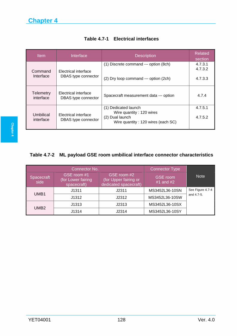
Chapter 4
YET04001 128 Ver. 4.0
Ch
apter 4
Table 4.7-1 Electrical interfaces
Item Interface Description Related section
Command Interface
Electrical interface DBAS type connector
(1) Discrete command --- option (8ch) (2) Dry loop command --- option (2ch)
4.7.3.1 4.7.3.2
4.7.3.3
Telemetry interface
Electrical interface DBAS type connector
Spacecraft measurement data --- option 4.7.4
Umbilical interface
Electrical interface DBAS type connector
(1) Dedicated launch Wire quantity : 120 wires
(2) Dual launch Wire quantity : 120 wires (each SC)
4.7.5.1
4.7.5.2
Table 4.7-2 ML payload GSE room umbilical interface connector characteristics
Connector No. Connector Type
Note Spacecraft side
GSE room #1 (for Lower fairing
spacecraft)
GSE room #2 (for Upper fairing or
dedicated spacecraft)
GSE room #1 and #2
UMB1 J1311 J2311 MS3452L36-10SN See Figure 4.7-4
and 4.7-5. J1312 J2312 MS3452L36-10SW
UMB2 J1313 J2313 MS3452L36-10SX
J1314 J2314 MS3452L36-10SY
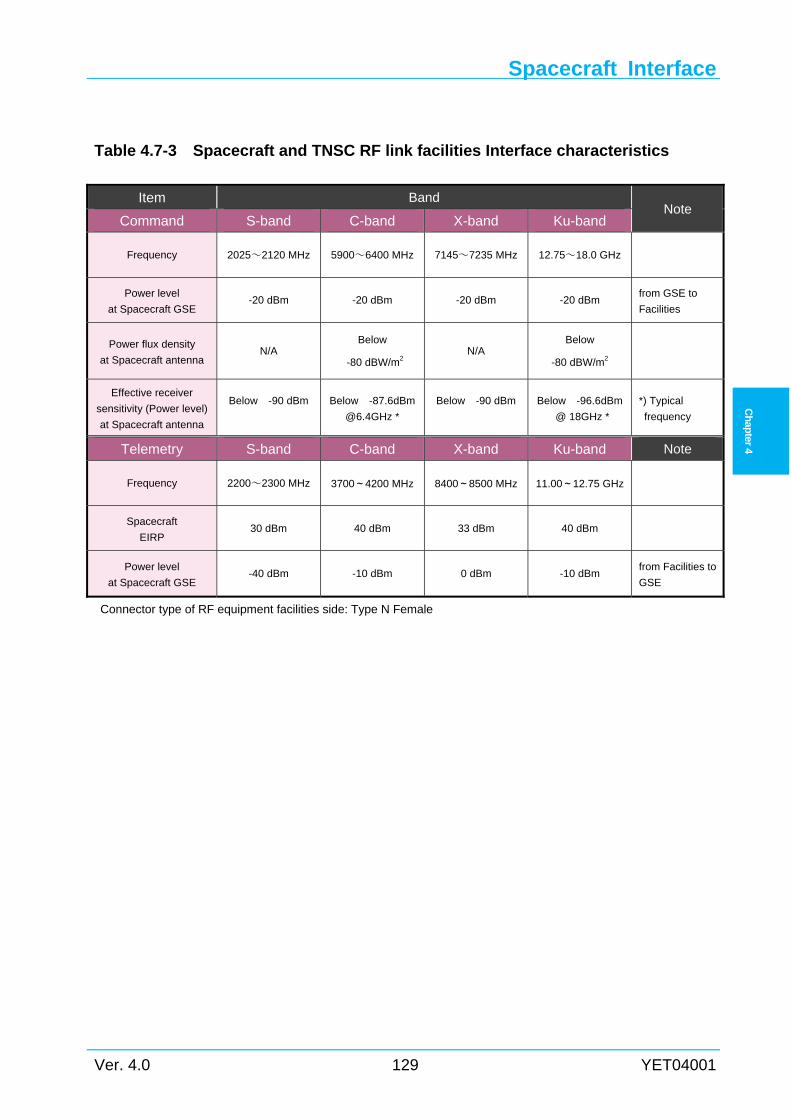
Spacecraft Interface
Ver. 4.0 129 YET04001
Ch
apter
4
Table 4.7-3 Spacecraft and TNSC RF link facilities Interface characteristics
Item Band Note
Command S-band C-band X-band Ku-band
Frequency 2025~2120 MHz 5900~6400 MHz 7145~7235 MHz 12.75~18.0 GHz
Power level
at Spacecraft GSE -20 dBm -20 dBm -20 dBm -20 dBm
from GSE to
Facilities
Power flux density
at Spacecraft antenna N/A
Below
-80 dBW/m2 N/A
Below
-80 dBW/m2
Effective receiver
sensitivity (Power level)
at Spacecraft antenna
Below -90 dBm
Below -87.6dBm
@6.4GHz *
Below -90 dBm
Below -96.6dBm
@ 18GHz *
*) Typical
frequency
Telemetry S-band C-band X-band Ku-band Note
Frequency 2200~2300 MHz 3700~4200 MHz 8400~8500 MHz 11.00~12.75 GHz
Spacecraft
EIRP 30 dBm 40 dBm 33 dBm 40 dBm
Power level
at Spacecraft GSE -40 dBm -10 dBm 0 dBm -10 dBm
from Facilities to
GSE
Connector type of RF equipment facilities side: Type N Female
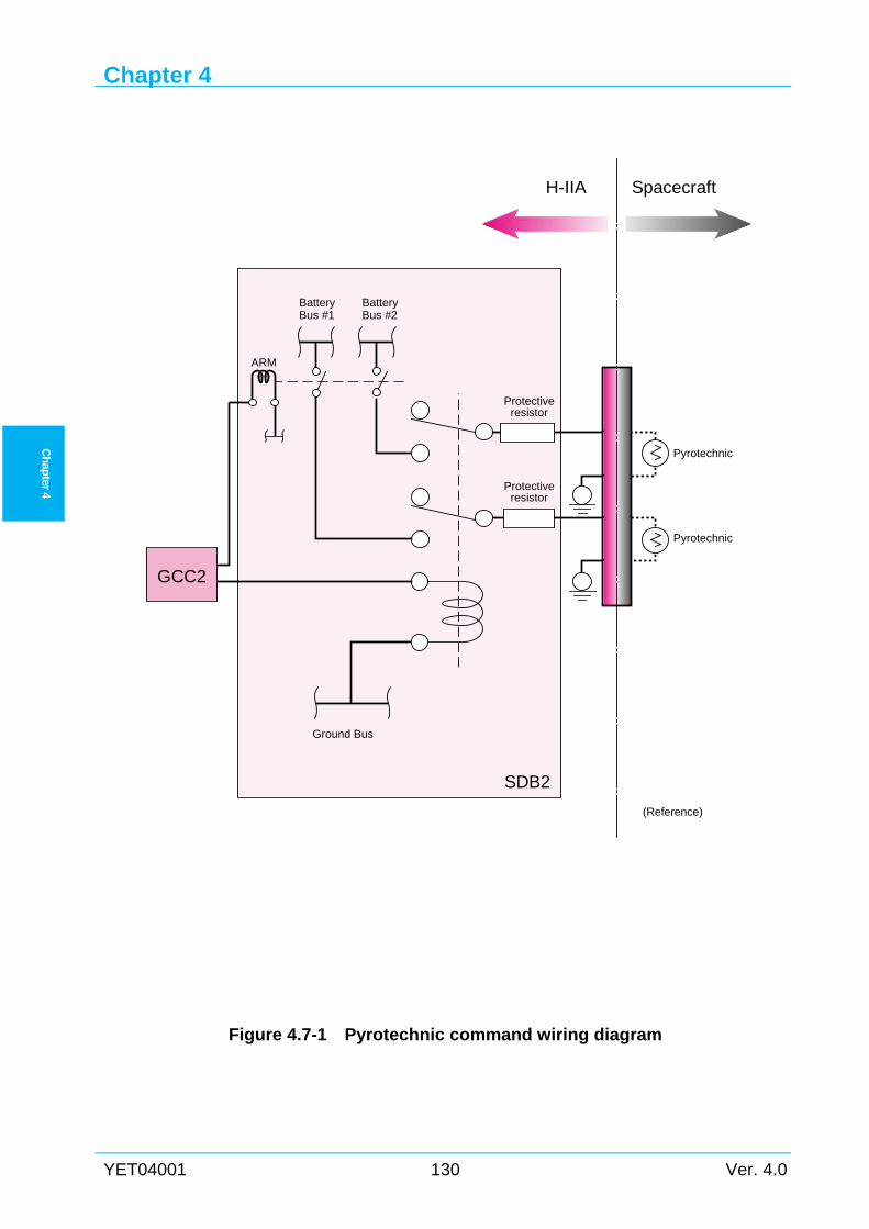
Chapter 4
YET04001 130 Ver. 4.0
Ch
apter 4
Figure 4.7-1 Pyrotechnic command wiring diagram
Pyrotechnic
Pyrotechnic
Protectiveresistor
Ground Bus
BatteryBus #1
BatteryBus #2
SpacecraftH-IIA
SDB2
(Reference)
GCC2
ARM
Protectiveresistor
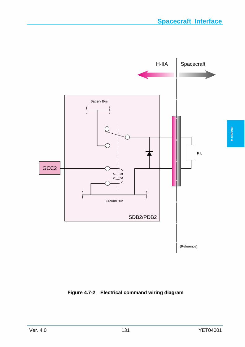
Spacecraft Interface
Ver. 4.0 131 YET04001
Ch
apter
4
Figure 4.7-2 Electrical command wiring diagram
Ground Bus
Battery Bus
SpacecraftH-IIA
SDB2/PDB2
R L
(Reference)
GCC2
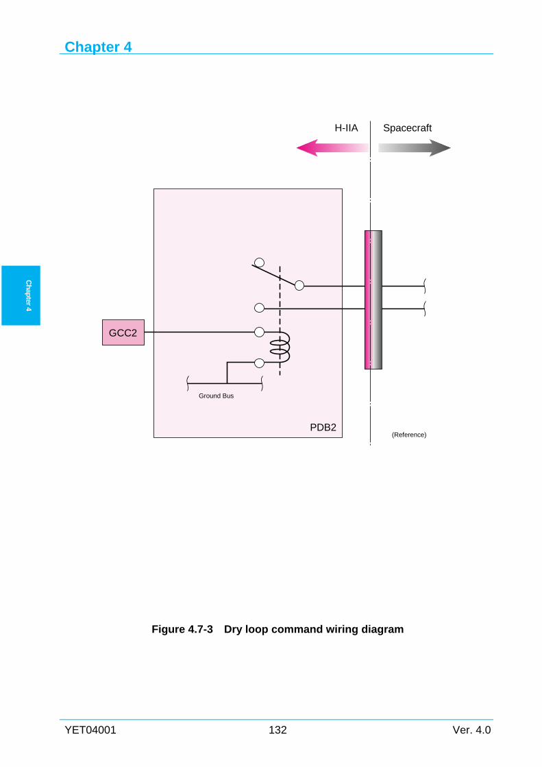
Chapter 4
YET04001 132 Ver. 4.0
Ch
apter 4
Figure 4.7-3 Dry loop command wiring diagram
Ground Bus
GCC2
SpacecraftH-IIA
PDB2(Reference)
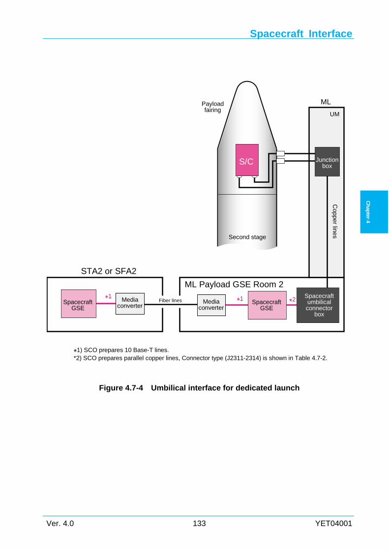
Spacecraft Interface
Ver. 4.0 133 YET04001
Ch
apter
4
Figure 4.7-4 Umbilical interface for dedicated launch
ML Payload GSE Room 2
STA2 or SFA2
Spacecraftumbilicalconnector
box
SpacecraftGSE
SpacecraftGSE
Mediaconverter
Mediaconverter
*1Fiber lines
Copper lines
Payloadfairing
Second stage
Junctionbox
UM
ML
S/C
*1 *2
*1) SCO prepares 10 Base-T lines.*2) SCO prepares parallel copper lines, Connector type (J2311-2314) is shown in Table 4.7-2.
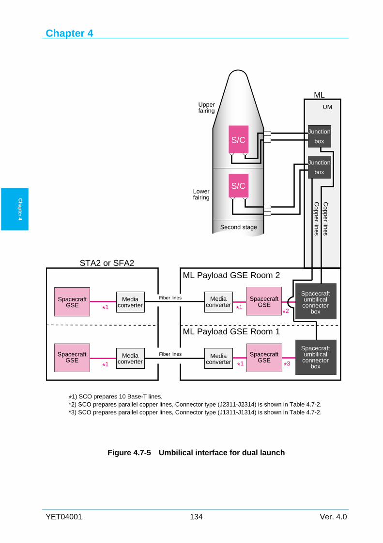
Chapter 4
YET04001 134 Ver. 4.0
Ch
apter 4
Figure 4.7-5 Umbilical interface for dual launch
Fiber lines
Fiber lines
ML Payload GSE Room 2
STA2 or SFA2
S/C
S/C
Copper lines
Upperfairing
Second stage
Lowerfairing C
opper lines
UM
ML
Spacecraftumbilicalconnector
box
SpacecraftGSE
Mediaconverter
SpacecraftGSE
Mediaconverter
SpacecraftGSE
SpacecraftGSE
Mediaconverter
Mediaconverter
Spacecraftumbilicalconnector
box
Junction
box
Junction
box
*1
*1
*1
*1
*1) SCO prepares 10 Base-T lines.*2) SCO prepares parallel copper lines, Connector type (J2311-J2314) is shown in Table 4.7-2.*3) SCO prepares parallel copper lines, Connector type (J1311-J1314) is shown in Table 4.7-2.
*3
*2
ML Payload GSE Room 1
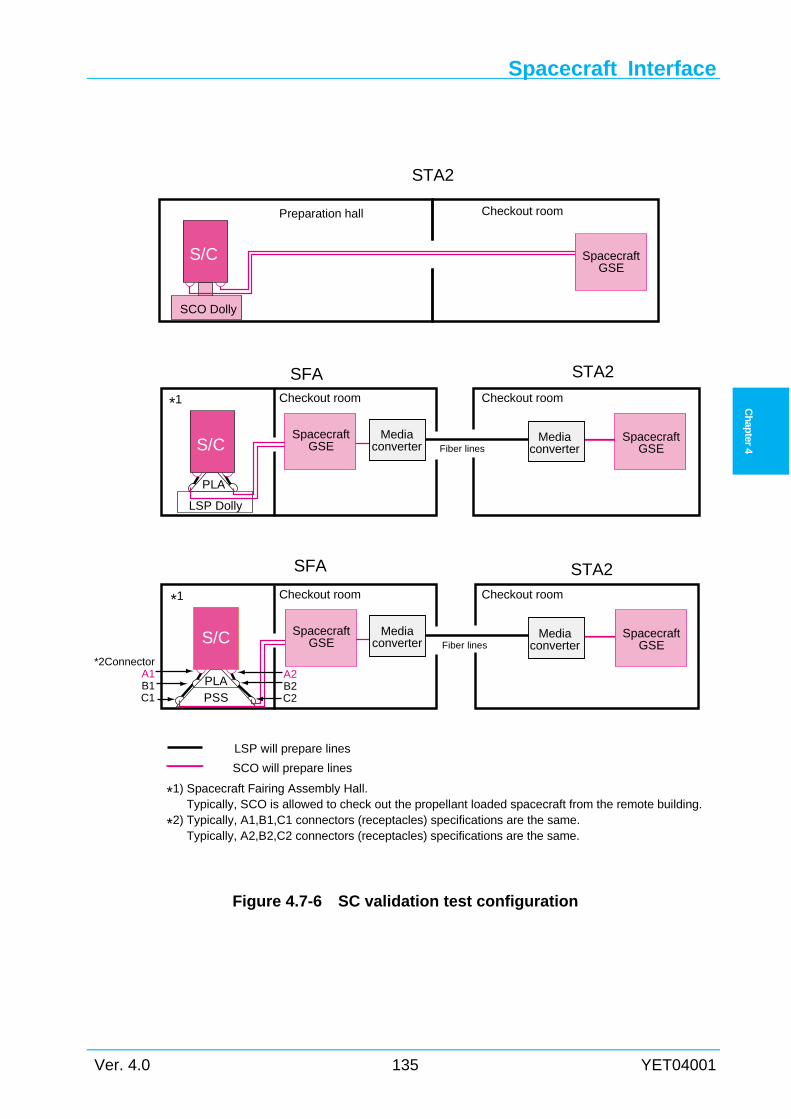
Spacecraft Interface
Ver. 4.0 135 YET04001
Ch
apter
4
Figure 4.7-6 SC validation test configuration
LSP will prepare lines
SCO will prepare lines
*1) Spacecraft Fairing Assembly Hall. Typically, SCO is allowed to check out the propellant loaded spacecraft from the remote building.
*2) Typically, A1,B1,C1 connectors (receptacles) specifications are the same. Typically, A2,B2,C2 connectors (receptacles) specifications are the same.
Fiber linesSpacecraft
GSEMedia
converterMedia
converter
*1 Checkout room
SpacecraftGSES/C
PLAPSS
STA2Checkout room
SFA
*2ConnectorA1B1C1
A2B2C2
Fiber lines
Checkout room
LSP Dolly
STA2
SpacecraftGSE
Mediaconverter
Mediaconverter
*1 Checkout room
SpacecraftGSES/C
PLA
SFA
Preparation hall
STA2
SpacecraftGSE
S/C
SCO Dolly
Checkout room
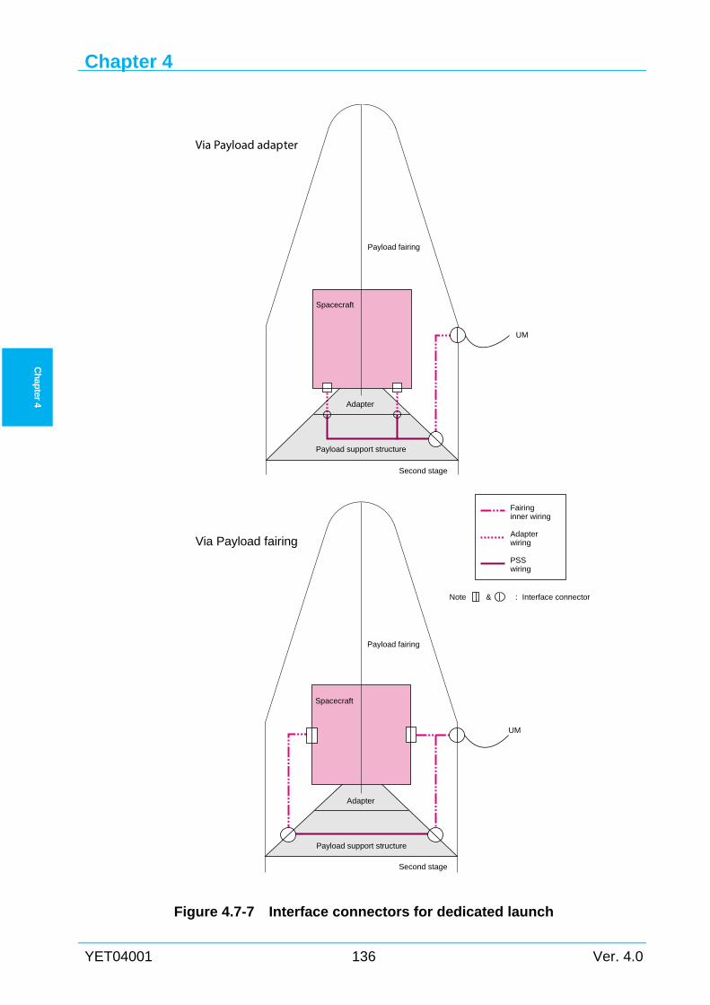
Chapter 4
YET04001 136 Ver. 4.0
Ch
apter 4
Figure 4.7-7 Interface connectors for dedicated launch
UM
Spacecraft
Second stage
Via Payload fairing
Adapter
Payload support structure
Fairinginner wiring
Adapterwiring
PSSwiring
Payload fairing
Payload fairing
Second stage
Via Payload adapter
Adapter
UM
Payload support structure
Spacecraft
Note & : Interface connector
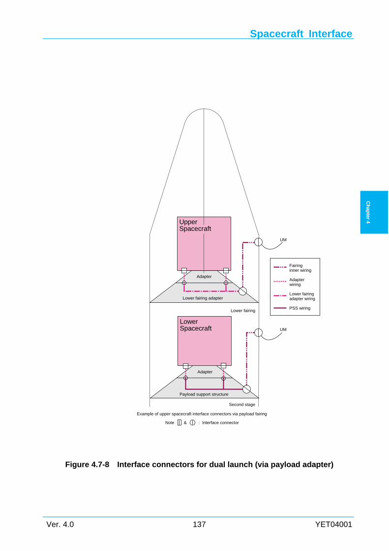
Spacecraft Interface
Ver. 4.0 137 YET04001
Ch
apter
4
Figure 4.7-8 Interface connectors for dual launch (via payload adapter)
Adapter
UpperSpacecraft
UM
Lower fairing
Second stage
Adapter
UM
Lower fairing adapter
Example of upper spacecraft interface connectors via payload fairing
Payload support structure
LowerSpacecraft
Note & : Interface connector
Fairinginner wiring
Adapterwiring
Lower fairingadapter wiring
PSS wiring
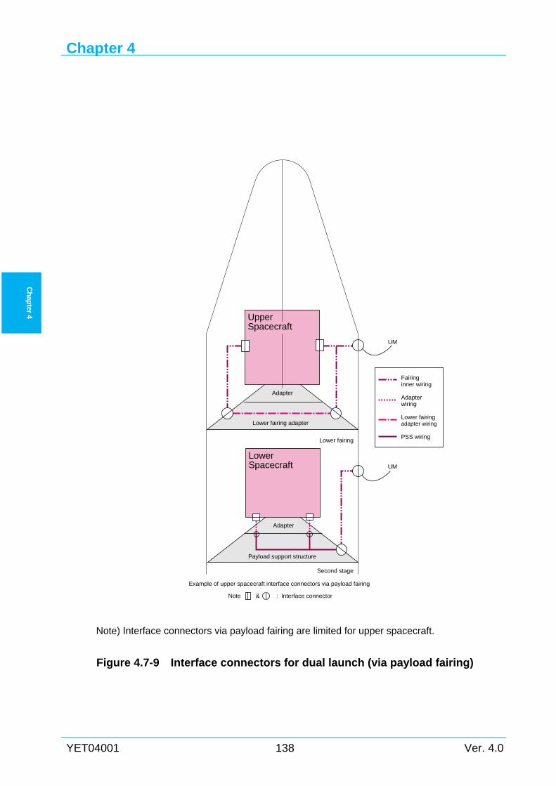
Chapter 4
YET04001 138 Ver. 4.0
Ch
apter 4
Note) Interface connectors via payload fairing are limited for upper spacecraft.
Figure 4.7-9 Interface connectors for dual launch (via payload fairing)
Adapter
UpperSpacecraft
UM
Lower fairing
Second stage
Adapter
UM
Lower fairing adapter
Example of upper spacecraft interface connectors via payload fairing
Payload support structure
LowerSpacecraft
Note & : Interface connector
Fairinginner wiring
Adapterwiring
Lower fairingadapter wiring
PSS wiring
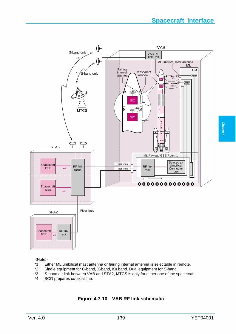
Spacecraft Interface
Ver. 4.0 139 YET04001
Ch
apter
4
<Note> *1 : Either ML umbilical mast antenna or fairing internal antenna is selectable in remote. *2 : Single equipment for C-band, X-band, Ku band. Dual equipment for S-band. *3 : S-band air link between VAB and STA2, MTCS is only for either one of the spacecraft. *4 : SCO prepares co-axial line.
Figure 4.7-10 VAB RF link schematic
*4
*4
*4
SFA2
ML Payload GSE Room 1
RF linkracks
UM
ML
S-band only*3
S-band only
*3
*1*2
*1
*1*2
*1
S/C
S/C
S/C
S/C
VAB
ML umbilical mast antenna
Fairinginternalantenna
Transparentwindow
Fiber lines
Fiber lines
SpacecraftGSE
SpacecraftGSE
STA 2
RF linkrack
SpacecraftGSE
AMP
MTCS
VAB RFlink Unit
Fiber lines
SpacecraftUmbilicalConnector
box
RF linkrack
AMP
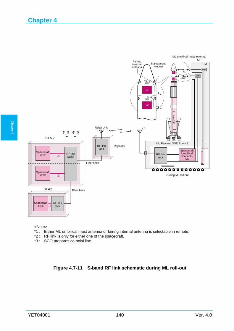
Chapter 4
YET04001 140 Ver. 4.0
Ch
apter 4
<Note> *1 : Either ML umbilical mast antenna or fairing internal antenna is selectable in remote. *2 : RF link is only for either one of the spacecraft. *3 : SCO prepares co-axial line.
Figure 4.7-11 S-band RF link schematic during ML roll-out
SpacecraftUmbilicalConnector
box
RF linkrack
AMP
AMP
SFA2
RF linkUnit
RF linkracks
UM
*2
*1*2
*1*1*2
*1
S/C
S/C
S/C
S/C
MLML umbilical mast antenna
Fairinginternalantenna
Transparentwindow
ML Payload GSE Room 1
SpacecraftGSE
SpacecraftGSE
STA 2
RF linkrack
SpacecraftGSE
Fiber lines
Fiber lines
Relay Unit
Repeater
During ML roll-out
*3
*3
*3
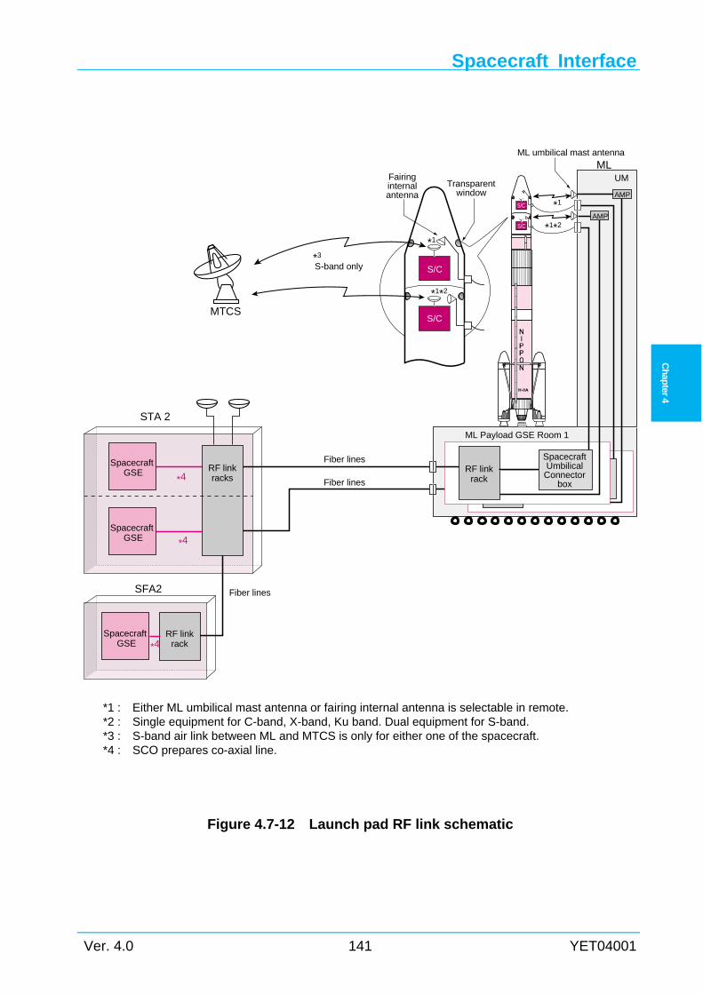
Spacecraft Interface
Ver. 4.0 141 YET04001
Ch
apter
4
*1 : Either ML umbilical mast antenna or fairing internal antenna is selectable in remote. *2 : Single equipment for C-band, X-band, Ku band. Dual equipment for S-band. *3 : S-band air link between ML and MTCS is only for either one of the spacecraft. *4 : SCO prepares co-axial line.
Figure 4.7-12 Launch pad RF link schematic
SpacecraftUmbilical
Connectorbox
RF linkrack
SFA2
RF linkracks
UM
S-band only*3
*1*2
*1
*1*2
*1
S/C
S/C
S/C
S/C
MLML umbilical mast antenna
Fairinginternalantenna
Transparentwindow
ML Payload GSE Room 1
SpacecraftGSE
SpacecraftGSE
STA 2
RF linkrack
SpacecraftGSE
AMP
AMP
MTCS
Fiber lines
Fiber lines
Fiber lines
*4
*4
*4
Chapter 4
YET04001 142 Ver. 4.0
Ch
apter 4
4.8 Other Ground Equipment Interfaces
4.8.1 Power TNSC has AC power generators. In launch campaign, AC power is provided by TNSC AC
generators. Backup generators are in standby status for another generator malfunction.
Spacecraft and launch vehicle processing buildings have CVCF (Constant Voltage Constant
Frequency) system. Several types of electrical power are available in TNSC, e.g.
(380V/220V/50Hz/60Hz for European), (220V/120V/60Hz/50Hz, for American), and
(100V/60Hz, for Japanese).
4.8.2 Liquids and gases All chemicals used will be in compliance with the requirements restricting ozone-depleting
chemicals. Gaseous helium (GHe) and gaseous nitrogen (GN2) are available at STA2, SFA2,
SFA and VAB for spacecraft use. The gas quality is MIL-P-27407A Type 1 Grade A or
equivalent for GHe, and MIL-P-27401C Type 1 Grade B or equivalent for GN2, respectively.
For more information regarding available liquids and gases, please contact LSP.
4.8.3 Fluid cleanliness and characteristics Analysis
Cleanliness and characteristics of liquids such as propellant (fuels, oxidizers), water, solvents,
and gases provided for spacecraft can be analyzed at Support Laboratory. For more information
regarding the analysis, please contact LSP.
4.8.4 Hazardous processing support facilities For spacecraft propellant loading and gas pressurization, a filling and assembly hall is
available at SFA and SFA2. The filling and assembly hall is built in consideration of the safety
of personnel who performs spacecraft hazardous processing. For hazardous processing (e.g.
propellant loading), safety equipment such as protective suits (SCAPE-suits), breathing air
system are available.
Chapter 5
Ver. 4.0 143 YET04001
Ch
apter 5
Chapter 5 LAUNCH OPERATIONS
5.1 General
5.1.1 Scope This chapter provides SCO with information on typical launch operations at the launch site.
SCO are required to meet the requirements specified in this chapter and specified in the “Launch
Vehicle Payload Safety Standard” for spacecraft and in the “Facility Guide for H-IIA Payload
Launch Campaign”, with respect to the safety management, the safety design and the launch site
operations at Tanegashima Space Center (TNSC).
5.2 Outline of the launch-related organizations Figure 1.2-1 shows the outline of LSP and its relationship with SCO. LSP will coordinate with
SCO regarding all issues during the launch campaign. Even issues related to ground safety, flight
safety, range safety, safety reviews, and launch facilities maintenance, LSP will coordinate with
JAXA TNSC and provide best solution for SCO. LSP will assign the Mission Manager as a
single point of contact with SCO for this purpose.
Chapter 5
YET04001 144 Ver. 4.0
Ch
apter 5
5.3 Launch Operations Requirements The launch operations requirements associated with the safety requirements, operations
interface requirements should be applied to the design and fabrication of spacecraft, the
spacecraft processing, and the launch operations.
After launch contract is signed, the documents (refer to Chapter 6) containing detailed
description of the interface will be prepared and updated in due course with the results at the
technical interchange meetings.
5.3.1 Safety requirements SCO shall meet the safety requirements specified in the “Launch Vehicle Payload Safety
Standard” (by JAXA). (Refer to Section 6.4.)
5.3.2 Launch operations interface requirements The launch operations interface requirements are specified in the interface documents
established by LSP with agreement of SCO, such as Spacecraft / H-IIA Interface Control
Document (ICD), Launch Operations Support Plan (LOSP), and Joint Operations Plan (JOP).
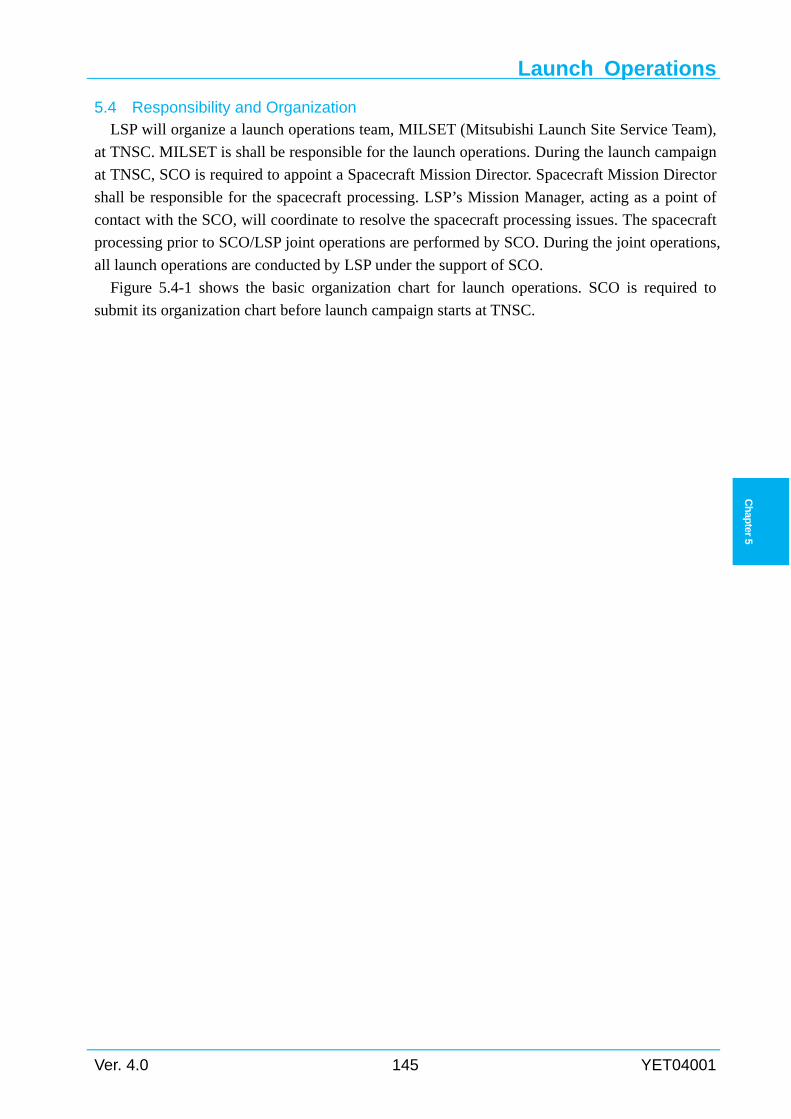
Launch Operations
Ver. 4.0 145 YET04001
Ch
apter 5
5.4 Responsibility and Organization LSP will organize a launch operations team, MILSET (Mitsubishi Launch Site Service Team),
at TNSC. MILSET is shall be responsible for the launch operations. During the launch campaign
at TNSC, SCO is required to appoint a Spacecraft Mission Director. Spacecraft Mission Director
shall be responsible for the spacecraft processing. LSP’s Mission Manager, acting as a point of
contact with the SCO, will coordinate to resolve the spacecraft processing issues. The spacecraft
processing prior to SCO/LSP joint operations are performed by SCO. During the joint operations,
all launch operations are conducted by LSP under the support of SCO.
Figure 5.4-1 shows the basic organization chart for launch operations. SCO is required to
submit its organization chart before launch campaign starts at TNSC.
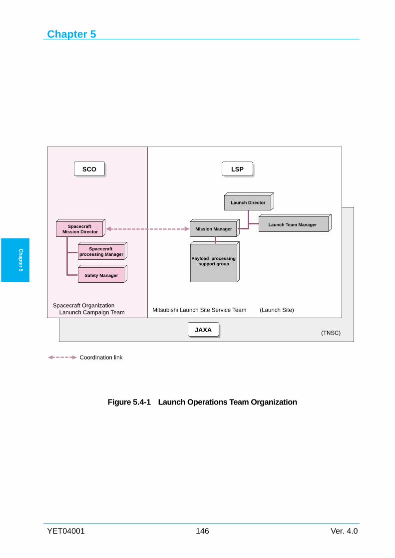
Chapter 5
YET04001 146 Ver. 4.0
Ch
apter 5
Figure 5.4-1 Launch Operations Team Organization
SpacecraftMission Director
Mission Manager
Launch Director
Launch Team Manager
Coordination link
Spacecraftprocessing Manager
Safety Manager
SCO LSP
JAXA
Mitsubishi Launch Site Service TeamSpacecraft Organization Lanunch Campaign Team (Launch Site)
(TNSC)
Payload processingsupport group
Launch Operations
Ver. 4.0 147 YET04001
Ch
apter 5
5.5 Restrictions
5.5.1 Restrictions on the ground In order to ensure safety, some spacecraft processing, such as RF radiation and battery charge,
will be required to operate by remote. Detailed restrictions will be coordinated and confirmed at
the technical interchange meetings.
5.5.2 Restrictions on launch This paragraph describes the launch window and launch related constraints. Details will be
presented at the technical interchange meetings.
Launch window 5.5.2.1(1) Launch Period and Launch Slot
Launch Period means a period equal to three (3) consecutive months which is preset at the
time of the contract. Launch Slot means a period equal to thirty (30) consecutive calendar
days which will be scheduled within the launch period. SCO and LSP will start coordination
of the launch slot 1 year before launch.
(2) Launch Day
Launch Day means a calendar day established for launch during the Launch Slot within
which the Launch Window is open. SCO and LSP will start coordination of Launch Day,
including alternative date, 6 months before launch. Launch Day will be publicly announced 2
months before launch.
(3) Launch Window
Launch Window means a time period during the Launch Day within which the Launch may
take place.
Launch Window will be determined by LSP considering restrictions and analyses such as sun
and shade, sun angle in the trajectory or insertion orbit, collision avoidance analysis with
manned spacecraft, and other relevant factors. To maximize launch opportunity, it is desirable
that launch window is 45 minutes or more because of the launch vehicle recycle activities.
Launch requirement and constraint 5.5.2.2Requirements and constraints for SCO before launch are shown below.
(1) Operations to access the spacecraft (e.g. detachment of Non-flight items, etc.) shall be
finished before fairing door close on L-1 day.
(2) Prior to ML roll-out, SCO should turn off the spacecraft and EGSE in ML/GSE room.
(3) After ML roll-out to LP, SCO shall check the spacecraft status via EGSE in ML/GSE
room by remote from STA2 or SFA2. After that, SCO shall evacuate from ML GSE room
by X-9.5hr.
(4) The spacecraft electrical power supply shall be switched from external to internal,
Chapter 5
YET04001 148 Ver. 4.0
Ch
apter 5
typically by X-15min. And preventing sparking at liftoff, low current signals shall be
allowed through the umbilical cable carries. Recommended voltage and current are 28
VDC, and less than 10 mA.
(5) Upon confirming that all spacecraft systems are ready for launch, SCO shall push the
“Ready” button by X-300s.
(6) If SCO postpones the launch because of anomaly, SCO shall push the “Emergency Stop”
button.
Launch criteria 5.5.2.3Typical launch criteria are shown below.
(1) Launch Vehicle
(a) Ground wind
(i) During ML roll-out: peak wind speed shall be below 22.4 m/s
(ii) At lift-off: peak wind speed shall be below 20.9 m/s
(b) Rain
(i) During ML roll-out: rainfall shall be below 15mm/h
(ii) At liftoff: rainfall shall be below 8mm/h
(iii) No falling hails during ML roll-out
(c) Cloud
No cumulonimbus clouds exist in the flight trajectory.
(d) Lightning
No atmospheric discharge exists in the flight trajectory at liftoff. (This is based on detailed
weather observation at liftoff phase.)
(i) No launch allowed if lightning is observed within 10 km of launch site
(ii) Launch suspended if lightning is observed within 20 km of the planned flight path
(iii) No launch allowed if lightning or cumulonimbus clouds* are observed in the planned
flight path
*) Including the clouds with 1.8km vertical thickness of freeze layer
(e) Flight wind
No launch allowed if the launch vehicle performance is adversely affected by the flight
wind profile as follows.
(i) Separated SRB-As are expected to fall out of the planned area.
(ii) Engine gimbal angle is expected to exceed the design limit.
(iii) Flight load is expected to exceed the design limit.
(2) Range Safety and Flight Safety
(a) Ground wind
Peak wind speed shall be below 20 m/s during tracking phase.
(b) Flight wind
No launch allowed if range safety is expected to be adversely affected by flight wind profile
as follows.
Launch Operations
Ver. 4.0 149 YET04001
Ch
apter 5
(i) Destructed objects are expected to fall outside the warning area when the launch
vehicle is destructed near the launch pad.
(c) Facilities
Range safety and flight safety systems shall be in operations.
(d) Collision Avoidance
Launch window shall be set taking into account that the launch vehicle and spacecraft will
not collide with manned spacecraft.
(e) Ground safety
It shall be confirmed that no one stays within the specified evacuation area.
(f) Maritime safety
It shall be confirmed that specified warning areas on the ocean are cleared.
Launch postponement 5.5.2.4In case that the launch vehicle cannot be launched within the launch window on the scheduled
date, launch will be postponed one (1) day or more. One (1) day is the minimum postponement
duration. In case that the postponement is determined after the launch vehicle propellant loading,
next launch day will be set typically after three (3) days from the first launch day. Depending on
the causes of the postponement, access to the spacecraft may be restricted. For each launch
mission, typical cases of postponement plan will be coordinated and established through the
meeting during the launch campaign.
Chapter 5
YET04001 150 Ver. 4.0
Ch
apter 5
5.6 TNSC Facilities and GSE Related to Spacecraft Processing The following describes the major facilities and GSE which can be utilized by SCO at TNSC.
The facilities and GSE actually utilized by SCO are specified in the Spacecraft / H-IIA ICD.
(a) No. 1 Spacecraft Test and Assembly Building (STA 1) and No.2 Spacecraft Test and
Assembly Building (STA 2) (spacecraft functional test)
(b) Spacecraft and Fairing Assembly Building (SFA) (propellant loading, battery
charging, encapsulating into the payload fairing, etc.)
(c) No. 2 Spacecraft and Fairing Assembly Building (SFA2) (spacecraft functional test,
propellant loading, encapsulating into the payload fairing, etc.)
(d) Vehicle Assembly Building (VAB) (mounting on launch vehicle, battery charging,
final checkout, arming, etc.)
(e) Movable Launcher (ML)
(f) Takesaki Range Control Center (RCC)
(g) Small satellite propellant loading building (SPLB)
(h) Fuel handling facility (FHF) , Oxidizer handling facility (OHF) (propellant handling)
(i) Pyrotechnics storage facility and solid propellant storage facility
(j) Nondestructive Test Facility (NDTF) (solid motor nondestructive inspection)
(k) Other specifically requested facilities and GSE
Figure 5.6-1 shows the location of spacecraft-related buildings in TNSC’s Osaki Range.
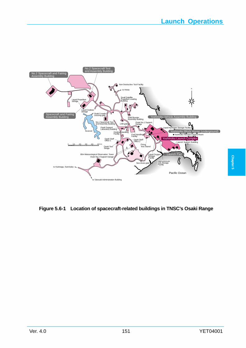
Launch Operations
Ver. 4.0 151 YET04001
Ch
apter 5
Figure 5.6-1 Location of spacecraft-related buildings in TNSC’s Osaki Range
Liquid Hydrogen Storage Facility
Liquid Propellantstorage
Liquid Oxidizerstorage
Spacecraft and FairingAssembly Building
No.2 Spacecraft and FairingAssembly Building
No.2 Spacecraft Testand Assembly Building
Small SatellitePropellant LoadingBuilding
Solid BoosterAssembly Building
to Hirota
Yoshinobu Launch Complex
Non-Destructive Test Facility
LSB gateOsaki No.1 SupportGarage
Osaki 5 roadscrossing gate
Yoshinobu Vehicle Assembly Building
Yoshinobu Block House (underground)Oxidizer HandlingFacility
Osaki StaffOffice 2
Sea shore gate
Liquid OxygenStorageFacility
High-pressureGas StorageFacility
FiringTest Stand
Launch Support Building
Yoshinobu Second Camera Room
No.1 Spacecraft Testand Assembly Building
Osaki SupportLaboratory Building
Osaki StaffOffice 1
Osaki ToolStrage
80m Meteorological Observation Tower
Pacific Ocean
Reservoir
to Kukinaga, Kaminaka
0 100 200 300 400 500 [m]
to Takesaki Administration Building
N
Launch Pad
Fuel HandlingFacility
Osaki No.2 Support Garage
Chapter 5
YET04001 152 Ver. 4.0
Ch
apter 5
5.7 Launch Operations This section describes the typical spacecraft processing and launch operations at TNSC.
5.7.1 Spacecraft processing The spacecraft processing at TNSC are classified into three phases:
Phase 1 Spacecraft preparation and functional test
Phase 2 Spacecraft hazardous processing
Phase 3 SCO and LSP Joint operations (integrated procedure)
In Phase 1, operations are performed independently by SCO in STA1, STA2 or SFA2. In this
phase, spacecraft processing activities are conducted under the responsibility of SCO with
support of LSP.
In Phase 2, operations are performed independently by SCO in SFA, SFA2, and others. In this
phase, spacecraft processing activities are conducted under the responsibility of SCO with
support of LSP.
In Phase 3, operations are performed jointly by SCO and LSP in SFA or SFA2 and VAB.
Operations from the spacecraft mating to payload adapter (PLA) and the payload support
structure (PSS) through the encapsulated spacecraft integration with the launch vehicle are
conducted by LSP with SCO support and witness.
Generally in the initial planning of spacecraft processing, SCO is expected to perform all
operations from delivery of the GSE (checkout equipment) to TNSC to its removal from TNSC
within 45 days (calendar days) (40 days before the launch, and five (5) days after the launch).
Figure 5.7-1 shows the typical spacecraft processing schedule.
Figure 5.7-2 shows the typical operations flow diagram for spacecraft preparation at TNSC.
5.7.2 Phase 1 (spacecraft preparation and functional test) After arrival at Tanegashima Airport, Nishino-omote Seaport or Shimama Seaport, the
spacecraft and GSE are transported to TNSC on the public roads. The spacecraft transported to
STA1, STA2 or SFA2, are unpacked and installed by SCO. LSP will support these tasks.
Hazardous materials, such as solid motors, pyrotechnics, propellant, and explosives, are
transported to the specified place where they are to be stored. Consumable materials, propellant
and high-pressure gas required for the spacecraft processing will be prepared by SCO or LSP,
depending on the contract.
The spacecraft is transported to the preparation room (clean room), and GSE is set up in the
checkout room adjacent to the test room. The spacecraft assembly and functional tests are
Launch Operations
Ver. 4.0 153 YET04001
Ch
apter 5
performed in STA1, STA2 or SFA2. Hazardous processing, such as pyrotechnics installing and
propellant loading, should not be performed in STA 1 and STA 2. However, inert high-pressure
gas systems may be charged if sufficient safety is ensured (this operation requires permission by
JAXA safety division).
After assembly and functional tests, the spacecraft are loaded into the container and
transported to SFA or SFA2 by LSP.
Figure 5.7-3 shows the typical Phase 1 operations flow diagram.
5.7.3 Phase 2 (hazardous processing for spacecraft) Hazardous processing such as installing solid motors and pyrotechnics, loading propellants,
and charging high-pressure gas systems shall be performed in SFA or SFA2. Hazardous
processing should be performed by the minimum required number (but more than two) of
persons who have received safety instruction and training. Other persons give operations
instructions or monitor the status from the monitor room. Only explosion-proof GSE can be set
up in the room where the hazardous processing is to be performed.
Figure 5.7-4 shows the typical Phase 2 processing flow diagram.
Preparing and assembling pyrotechnics and solid motor 5.7.3.1Before installation on the spacecraft, pyrotechnics and solid motor should be inspected in
NDTF (pyrotechnics only).
After inspection and assembly, the pyrotechnics are transported into SFA or SFA2. All these
operations, including transportation between buildings, shall be under the responsibility of SCO.
LSP will support operations requiring use of the TNSC equipment and materials.
Hazardous processing 5.7.3.2(1) Transport (by LSP, non-hazardous operations)
The spacecraft is loaded in the container, transported from STA 1, STA 2, to SFA and
unloaded from the trailer in the air lock. After the cleanliness in the air lock room has been
established, the spacecraft is taken out of the container and is moved into the assembly room
(clean room). Figure 5.7-5 shows typical transport operations.
(2) Loading the propellant and charging the high-pressure gas system
The propellant and the high-pressure gas for pressurization up to the flight level are loaded
in SFA or SFA2 (or in VAB for special cases) by SCO. Also the operations such as
depressurization, purging and flushing should be under the responsibility of SCO. Battery
charge after propellant loading is allowed at SFA or SFA2 from remote building, under the
condition that other operations are not conducting.
(3) Installing the pyrotechnics
The pyrotechnics and the solid motor can be installed by SCO in SFA or SFA2. However,
pyrotechnics wire connection and arming should be conducted by SCO in VAB as part of the
countdown operations.
Chapter 5
YET04001 154 Ver. 4.0
Ch
apter 5
Final spacecraft assembly 5.7.3.3(1) Weight measurement
The spacecraft can be weighed in STA1, STA2, SFA or SFA2 under the responsibility of
SCO. LSP will request SCO to weigh the spacecraft, concerning its effect on flight
performance. Whether the weight is to be measured before or after loading the propellant and
charging the high-pressure gas systems will be determined by coordination with SCO.
SCO can utilize the weighing equipment of TNSC.
(2) Final inspection
Electrical and mechanical inspection and solid propellant motor arming inspection must be
completed before spacecraft encapsulation into the payload fairing.
After entering Phase 3 operations, direct access to the launch vehicle body (including the
spacecraft) is allowed only when it is approved in the technical interchange meeting. The
operations by telecommunications signals via the umbilical line or RF signals are allowed at
SFA or SFA2 from remote building under the condition that other operations are not
conducting.
5.7.4 Phase 3 (Joint operations by SCO and LSP) Phase 3 consists of joint operations by SCO and LSP. Operations from mating the spacecraft
to the payload adapter (PLA) / the payload support structure (PSS) through mounting the
encapsulated spacecraft on the launch vehicle are conducted by LSP. SCO will support and
witness.
Figure 5.7-6 shows the typical Phase 3 operations flow diagram for a dedicated launch.
Figure 5.7-7 shows the typical Phase 3 operations flow diagram for a dual launch.
The spacecraft and PLA mating can be performed in earlier phase.
Encapsulation into the payload fairing 5.7.4.1The first operations in Phase 3 (joint operations by SCO and LSP) are to mate the spacecraft to
the PLA, to mount them on the PSS and to encapsulate them into the payload fairing in SFA or
SFA2. These operations are performed by LSP with the support of SCO. The spacecraft is
usually handled together with PLA by means of the handling jig prepared by SCO. The
additional weight of the adapter must be considered in the spacecraft and spacecraft handling jig
design.
Encapsulation for dedicated launch 5.7.4.2After the checkout of the spacecraft in SFA or SFA2, the spacecraft is encapsulated into the
payload fairing. The major operations here are as follows:
(1) The spacecraft is mated to the PLA, and then mounted on the PSS. The pyrotechnics for
the spacecraft separation is also installed.
Launch Operations
Ver. 4.0 155 YET04001
Ch
apter 5
(2) The payload fairing encapsulates the spacecraft from the top, and then the fairing bottom
flange and forward connection flange of the PSS are bolted to each other. (In case of the
Model 5S fairing, each half-fairing is mated with the PSS.)
Figure 5.7-8 shows the typical encapsulation sequence for dedicated launch.
Encapsulation for dual launch 5.7.4.3After the checkout of the spacecraft in SFA or SFA2, two spacecraft are encapsulated into the
payload fairing separately. The major operations here are as follows:
(1) The lower spacecraft is mated to the PLA, and then mounted on the PSS. The
pyrotechnics for the spacecraft separation is also installed.
(2) The lower payload fairing for a dual launch (hereafter referred to as the lower fairing)
encapsulates from top of the lower spacecraft and then the bottom flange of the lower
fairing is bolted to the connection flange of the lower PSS.
(3) The upper spacecraft is mated to the PLA and the pyrotechnics for the spacecraft
separation is installed.
(4) The upper spacecraft with the PLA is mounted on the upper PSS which is connected to the
forward end of the lower fairing.
(5) The upper fairing encapsulates from top of the upper spacecraft and then the upper fairing
is bolted to the upper PSS.
Figure 5.7-9 shows the typical encapsulation sequence for a dual launch.
Transportation of encapsulated spacecraft 5.7.4.4The encapsulated spacecraft is loaded on the spacecraft/fairing trailer in SFA or SFA2 air lock
room and transported to VAB. After arrival to VAB, the encapsulated spacecraft is unloaded from
the trailer and hoisted.
Figure 5.7-9 shows the typical transportation sequence of the encapsulated spacecraft.
During transportation except for hoisting, LSP monitors the following conditions.
Temperature : 5 ºC to 30 ºC (target value is selectable in Table 3.3-1)
Humidity : less than 60 % RH
Vibration : less than 17.7m/s20-P (1.8 G 0-P) (each axis)
Mounting on launch vehicle 5.7.4.5After the encapsulated spacecraft is hoisted on the upper floor of VAB, it is directly mounted
on the top of the second stage. After that, the air conditioning duct is connected to the fairing,
and the payload fairing assembly transport jig is removed and then quick disconnect (QD) and
fairing separation pyrotechnics are installed to their positions.
Figure 5.7-10 shows the typical sequence of mounting the encapsulated spacecraft on the
Chapter 5
YET04001 156 Ver. 4.0
Ch
apter 5
launch vehicle.
Spacecraft inspection after installation 5.7.4.6The spacecraft functional test can be conducted according to the joint operations schedule
determined in advance. Details will be determined at the technical interchange meetings and the
coordination meetings before joint operations. This also applies to the RF link test, leakage
inspection, battery charging, and visual inspection. Spacecraft arming and disarming operations
shall be inspected and witnessed by JAXA launch site safety division. During these operations,
turning on the electric system or RF radiation system is prohibited. The electric or RF radiation
systems of the spacecraft are prohibited to operate during the installation of pyrotechnics of the
launch vehicle. While some propulsion system operations are being performed, switching may be
prohibited. Details will be determined during the joint operations schedule coordination with
LSP.
L-5 operations 5.7.4.7The final preparation for the countdown configuration is performed during pre-countdown
operations. Details will be determined at the technical interchange meetings and the coordination
meeting before countdown.
L-4 ~ L-0 operations 5.7.4.8SCO will perform the final functional test using the ground line and RF, and charge the battery
within the specified time. Details will be determined at the technical interchange meeting and the
coordination meeting before the launch countdown operations. Figure 5.7-12 shows the typical
countdown schedule. The following gives some parts of restricted operations during the launch
countdown operations.
(1) Hazardous operations
(a) Leak check of the high pressure bottle of the launch vehicle (L-4)
During this operation, access to the spacecraft is prohibited. (VAB entrance is
controlled.)
(b) Loading propellant for the second stage gas jet system of the launch vehicle (L-3)
During this operation, all of spacecraft processing are prohibited. (VAB entrance is
controlled.)
(c) Pyrotechnics wire connection by LSP (L-3)
During this operation, spacecraft processing such as switching or turning on the electric
and RF radiation system are prohibited.
(d) Vehicle body arming by LSP (L-2)
During this operation, spacecraft processing such as switching or turning on the electric
and RF radiation system are prohibited.
(2) Others
(a) Final door close (L-1)
Launch Operations
Ver. 4.0 157 YET04001
Ch
apter 5
Until L-1 final door close, SCO shall finish accessing to the spacecraft. After this event,
SCO cannot access the spacecraft directly.
(b) ML roll-out (L-0)
ML is rolled out from VAB and mounted on the LP. During this operation, SCO should
turn off the SC and EGSE. After the ML roll-out to LP, SCO shall check the SC via
EGSE at ML GSE room from STA2 or SFA2 by remote. After that operation, SCO shall
evacuate from ML GSE room by X-9.5hr.
In case of a dual spacecraft launch, all restrictions from each spacecraft side will be imposed
on each other. The problems will be coordinated at the technical interchange meeting and the
coordination meeting before the launch countdown operations.
Chapter 5
YET04001 158 Ver. 4.0
Ch
apter 5
Terminal countdown 5.7.4.9Figure 5.7-13 shows the typical terminal countdown sequence of the H-IIA launch vehicle on
the launch date (L-0). During terminal countdown, SCO will perform the following operations:
(1) Spacecraft flight configuration
The final spacecraft flight configuration that includes the completion of switching power
supply or arming pyrotechnic devices etc. should be expected to be established before
X-15(generally) minutes.
Then, SCO will inform the status to the Launch Director via Mission Manager of LSP in
order to make X-10 minutes Final Go/No-Go poll.
(2) Completion of spacecraft preparation
SCO shall conduct the final inspection and system check up to X-300 seconds and press
the ready button that is one of the prerequisite for the automatic countdown sequence start.
(3) Automatic countdown sequence
LSP starts the automatic countdown sequence after X-270 seconds.
(4) Countdown recycle
If the recycle command is issued during the countdown, all countdown operations are
reset to X-25 minutes.
Recycle operations (Launch postponement) 5.7.4.10If the launch is postponed on the launch date, recycle operations are performed. The major
recycle operations are as follows:
(a) Discharging the launch vehicle propellant and purging
(b) Transporting the ML to VAB
(c) Disarming spacecraft systems (if required)
(d) Disarming launch vehicle systems (if required)
(e) Operations required for repetition of L-1
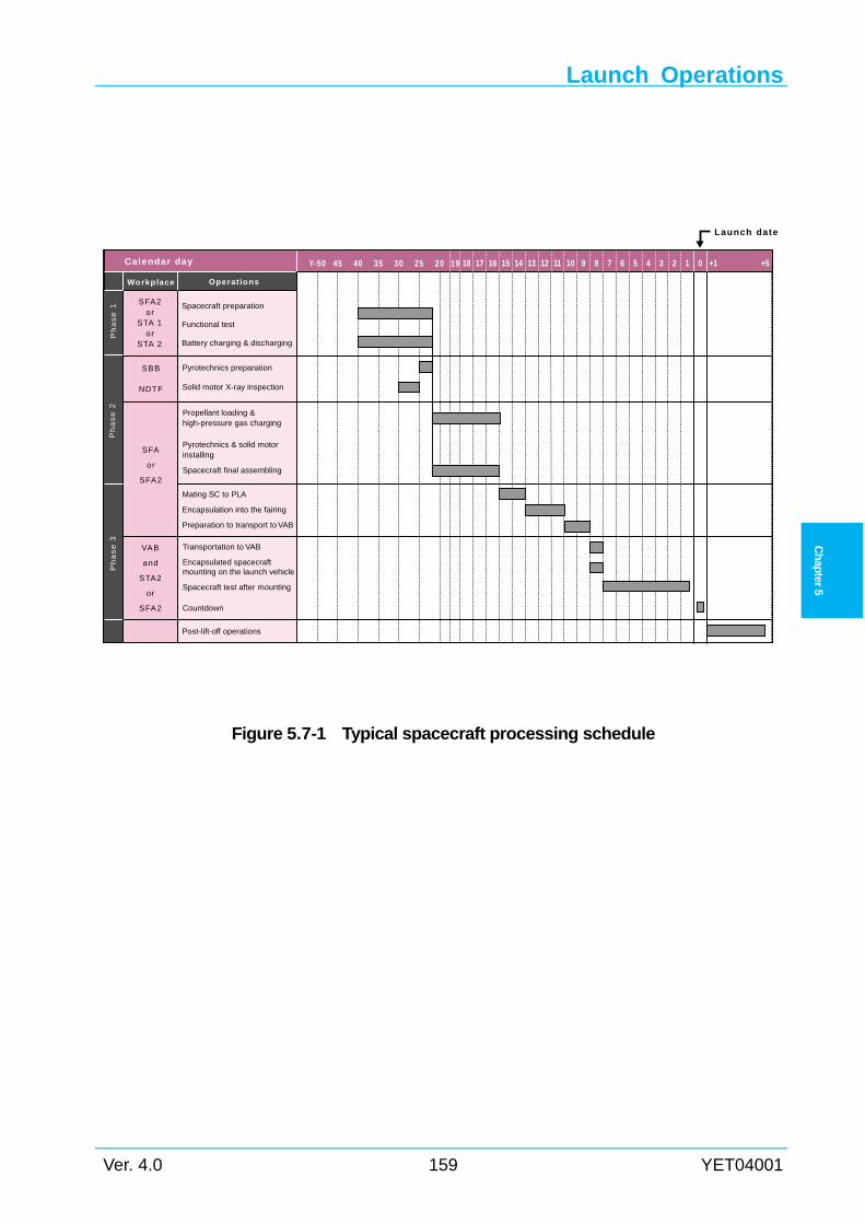
Launch Operations
Ver. 4.0 159 YET04001
Ch
apter 5
Figure 5.7-1 Typical spacecraft processing schedule
Spacecraft preparation
Functional test
Battery charging & discharging
Ph
as
e 1
SFA2or
STA 1or
STA 2
Pyrotechnics preparation
Solid motor X-ray inspection
Propellant loading &high-pressure gas charging
Pyrotechnics & solid motorinstalling
Spacecraft final assembling
Mating SC to PLA
Encapsulation into the fairing
Preparation to transport to VAB
Transportation to VAB
Encapsulated spacecraftmounting on the launch vehicle
Spacecraft test after mounting
Countdown
Ph
as
e 2
Ph
as
e 3
SBB
NDTF
SFA
or
SFA2
VAB
and
STA2
or
SFA2
Workplace Operations
Calendar day Y-50 45 40 35 30 25 20 19
Post-lift-off operations
18 17 16 15 14 13 12 11 10 9 8 7 6 5 4 3 2 1 0 +1
Launch date
+5
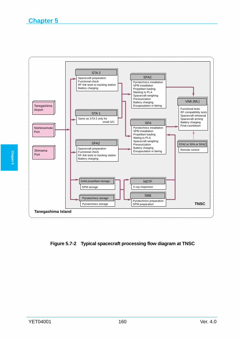
Chapter 5
YET04001 160 Ver. 4.0
Ch
apter 5
Figure 5.7-2 Typical spacecraft processing flow diagram at TNSC
Spacecraft preparationFunctional checkRF link tests to tracking stationBattery charging
Same as STA 2 only for small S/C
Functional testsRF compatibility testsSpacecraft rehearsalSpacecraft armingBattery chargingFinal countdown
STA2 or SFA or SFA2
SPM storage
Pyrotechnics storage
X-ray inspection
Pyrotechnics preparationSPM preparation
Pyrotechnics installationSPM installationPropellant loadingMating to PLASpacecraft weighingPressurizationBattery chargingEncapsulation in fairing
TanegashimaAirport
NishinoomotePort
ShimamaPort
STA 2
Spacecraft preparationFunctional checkRF link tests to tracking stationBattery charging
Pyrotechnics installationSPM installationPropellant loadingManting to PLASpacecraft weighingPressurizationBattery chargingEncapsulation in fairing
SFA2
SFA
VAB (ML)
Remote control
STA 1
Solid propellant storage
Pyrotechnics storage
NDTF
SBB
SFA2
TNSC
Tanegashima Island
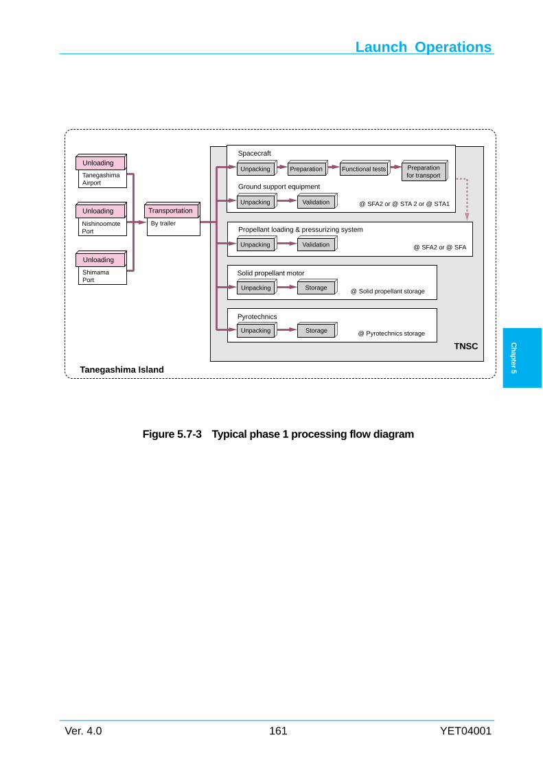
Launch Operations
Ver. 4.0 161 YET04001
Ch
apter 5
Figure 5.7-3 Typical phase 1 processing flow diagram
NishinoomotePort
ShimamaPort
By trailer
Preparationfor transport
Unpacking Preparation Functional tests
Validation @ SFA2 or @ STA 2 or @ STA1Unpacking
ValidationUnpacking
Spacecraft
Ground support equipment
Propellant loading & pressurizing system
Storage@ Solid propellant storageUnpacking
@ SFA2 or @ SFA
@ Pyrotechnics storageStorageUnpacking
Solid propellant motor
Pyrotechnics
TanegashimaAirport
Unloading
Unloading
Unloading
Transportation
Tanegashima Island
TNSC
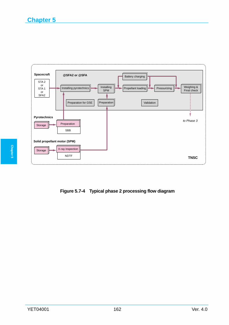
Chapter 5
YET04001 162 Ver. 4.0
Ch
apter 5
Figure 5.7-4 Typical phase 2 processing flow diagram
Validation
Spacecraft
Weighing &Final check
Propellant loading PressurizingInstallingSPM
Installing pyrotechnics
Battery charging
PreparationPreparation for GSE
PreparationStorage
Storage
Pyrotechnics
STA 2or
STA 1or
SFA2
Solid propellant motor (SPM)
NDTF
to Phase 3
SBB
X-ray inspection
@SFA2 or @SFA
TNSC
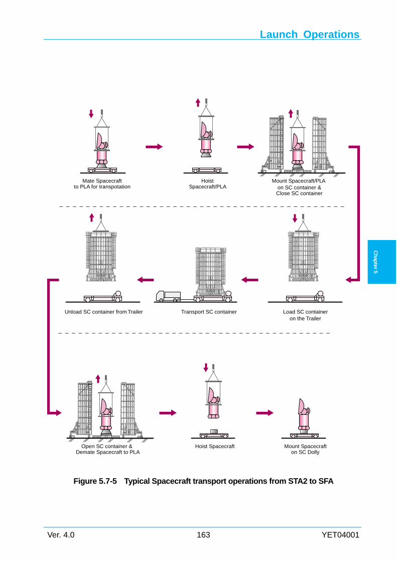
Launch Operations
Ver. 4.0 163 YET04001
Ch
apter 5
Figure 5.7-5 Typical Spacecraft transport operations from STA2 to SFA
Mate Spacecraftto PLA for transpotation
HoistSpacecraft/PLA
Mount Spacecraft/PLAon SC container &Close SC container
Load SC containeron the Trailer
Transport SC containerUnload SC container from Trailer
Open SC container &Demate Spacecraft to PLA
Hoist Spacecraft Mount Spacecrafton SC Dolly
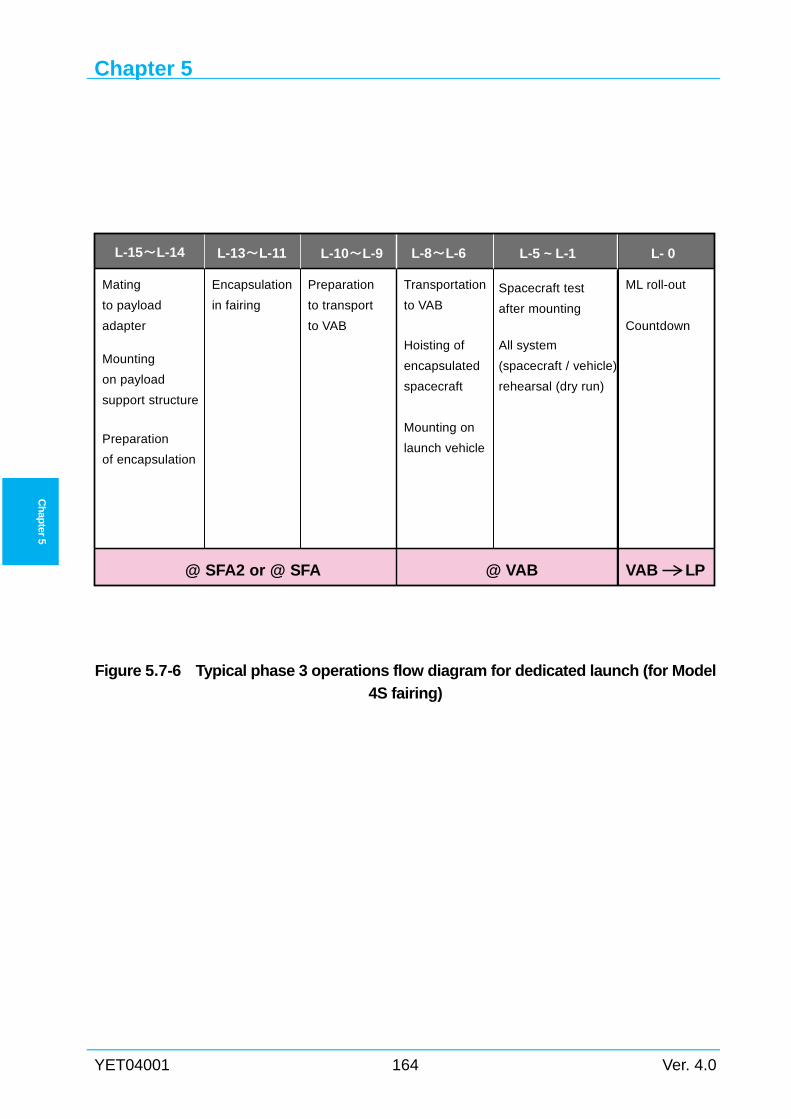
Chapter 5
YET04001 164 Ver. 4.0
Ch
apter 5
Figure 5.7-6 Typical phase 3 operations flow diagram for dedicated launch (for Model
4S fairing)
Mating
to payload
adapter
Preparation
of encapsulation
Encapsulation
in fairing
Preparation
to transport
to VAB
to VAB
Transportation
spacecraft
encapsulated
Hoisting of
launch vehicle
Mounting on
rehearsal (dry run)
(spacecraft / vehicle)
All system
Spacecraft test
after mountingCountdown
ML roll-out
@ SFA2 or @ SFA @ VAB VAB LP
L-15~L-14 L-13~L-11 L-10~L-9 L-8~L-6 L-5 ~ L-1 L- 0
Mounting
on payload
support structure
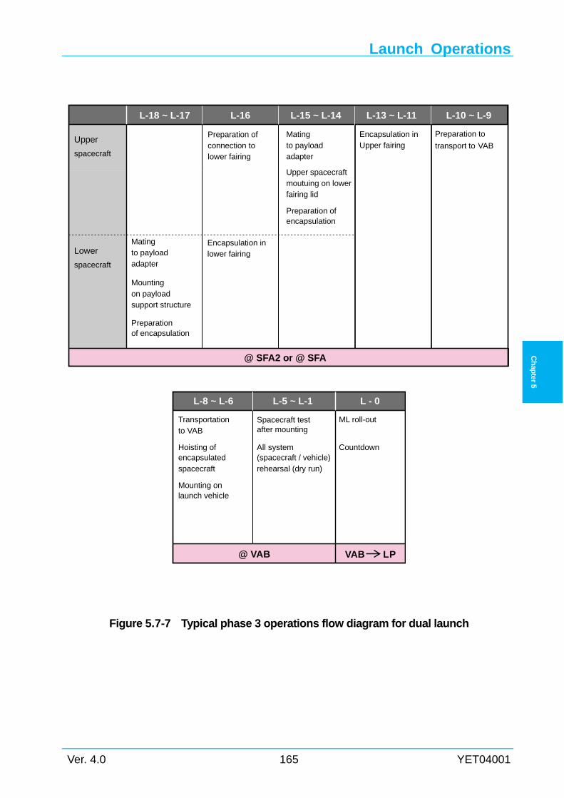
Launch Operations
Ver. 4.0 165 YET04001
Ch
apter 5
Figure 5.7-7 Typical phase 3 operations flow diagram for dual launch
L-18 ~ L-17 L-16 L-15 ~ L-14 L-13 ~ L-11 L-10 ~ L-9
Upper
spacecraft
Preparation ofconnection tolower fairing
Matingto payloadadapter
Preparation ofencapsulation
Encapsulation inUpper fairing
Preparation to
transport to VAB
Lower
spacecraft
Mountingon payloadsupport structure
Preparationof encapsulation
Encapsulation inlower fairing
@ SFA2 or @ SFA
Matingto payloadadapter
Upper spacecraftmoutuing on lowerfairing lid
L-8 ~ L-6 L-5 ~ L-1 L - 0
Transportationto VAB
Hoisting ofencapsulatedspacecraft
Mounting onlaunch vehicle
All system(spacecraft / vehicle)rehearsal (dry run)
Spacecraft testafter mounting
Countdown
ML roll-out
@ VAB VAB LP
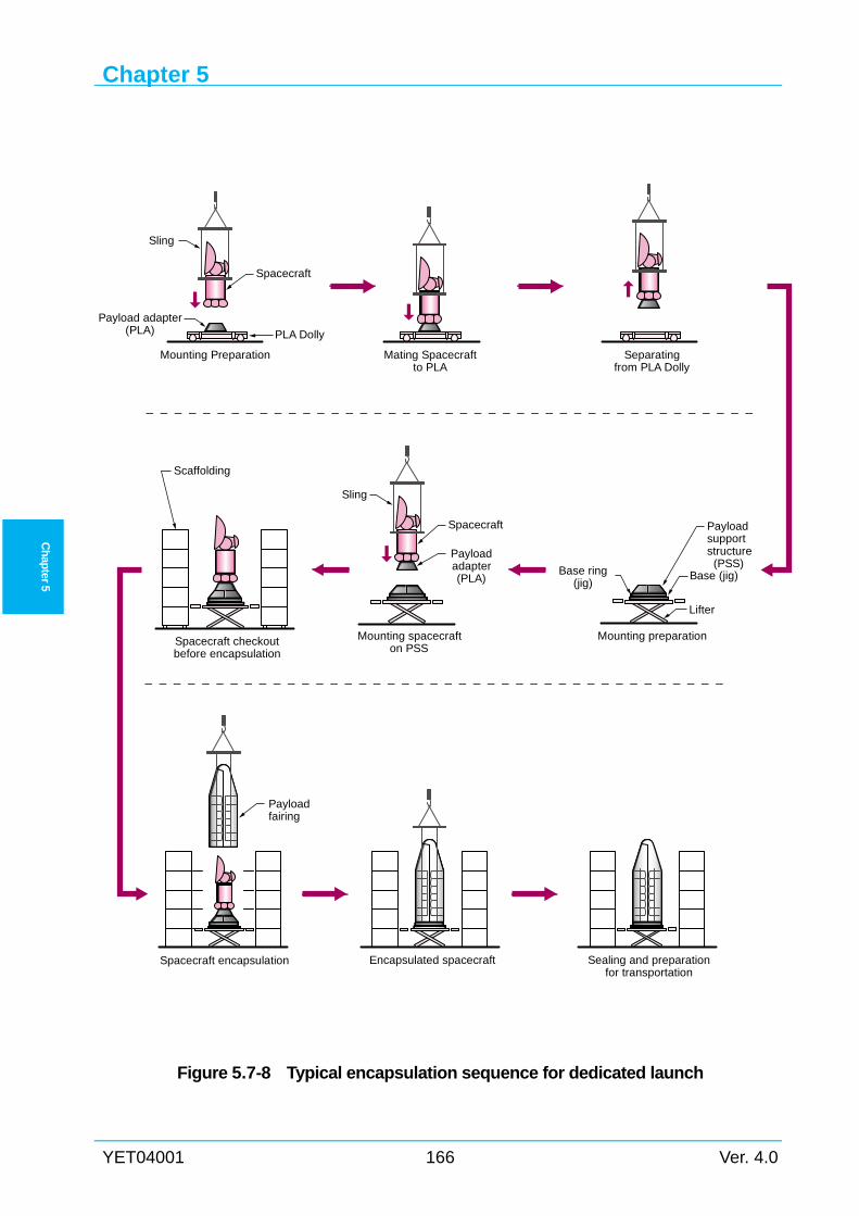
Chapter 5
YET04001 166 Ver. 4.0
Ch
apter 5
Figure 5.7-8 Typical encapsulation sequence for dedicated launch
Base (jig)
Payloadsupportstructure (PSS)
Base ring(jig)
Mounting preparation
Lifter
Sling
Spacecraft
Sling
Payload adapter(PLA)
Spacecraft
Payloadadapter(PLA)
Mounting spacecrafton PSS
Scaffolding
Spacecraft checkoutbefore encapsulation
Encapsulated spacecraft Sealing and preparationfor transportation
Spacecraft encapsulation
Payloadfairing
PLA Dolly
Separatingfrom PLA Dolly
Mating Spacecraftto PLA
Mounting Preparation
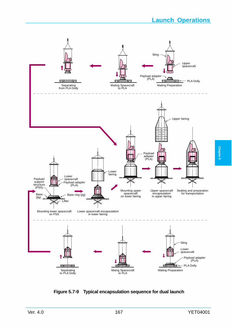
Launch Operations
Ver. 4.0 167 YET04001
Ch
apter 5
Figure 5.7-9 Typical encapsulation sequence for dual launch
Lowerspacecraft
Separatingto PLA Dolly
Maing Spacecraftto PLA
Mating Preparation
PLA Dolly
Sling
Payload adapter(PLA)
Payloadadapter(PLA)
Lowerfairing
Lower spacecraft encapsulationin lower fairing
Payload adapter(PLA)
Lowerspacecraft
Base(jig)
Base ring (jig)
Lifter
Mounting lower spacecrafton PSS
Upper fairing
Sealing and preparationfor transportation
Upper spacecraftencapsulationin upper fairing
Mounting upperspacecraft
on lower fairing
Payloadsupport
structure(PSS)
Upperspacecraft
Sling
Payload adapter(PLA)
PLA Dolly
Separatingfrom PLA Dolly
Mating Spacecraftto PLA
Mating Preparation
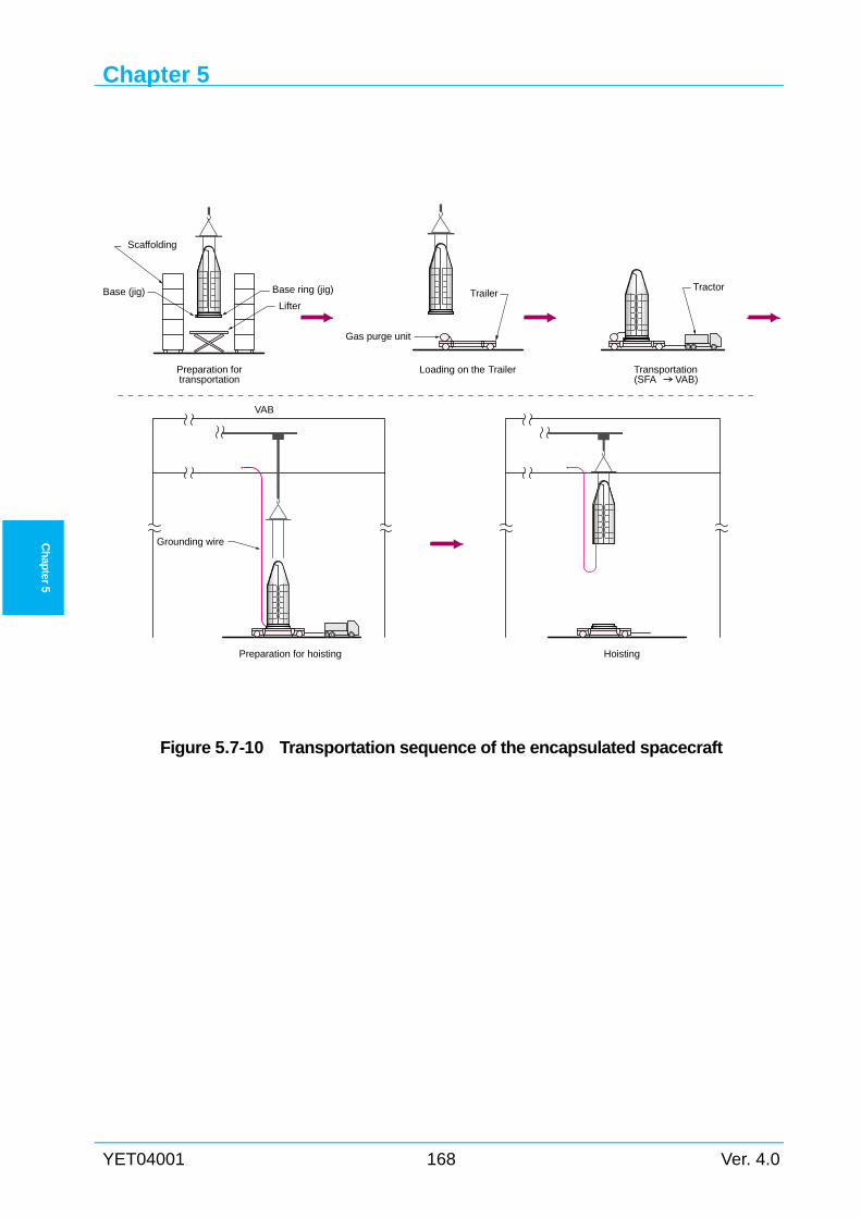
Chapter 5
YET04001 168 Ver. 4.0
Ch
apter 5
Figure 5.7-10 Transportation sequence of the encapsulated spacecraft
TractorTrailer
Scaffolding
Gas purge unit
Lifter
Base (jig) Base ring (jig)
Preparation fortransportation
Loading on the Trailer Transportation(SFA VAB)
Grounding wire
Preparation for hoisting Hoisting
VAB
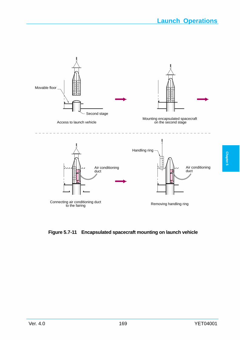
Launch Operations
Ver. 4.0 169 YET04001
Ch
apter 5
Figure 5.7-11 Encapsulated spacecraft mounting on launch vehicle
Second stage
Movable floor
Handling ring
Air conditioningduct
Air conditioningduct
Connecting air conditioning ductto the fairing
Access to launch vehicleMounting encapsulated spacecraft
on the second stage
Removing handling ring
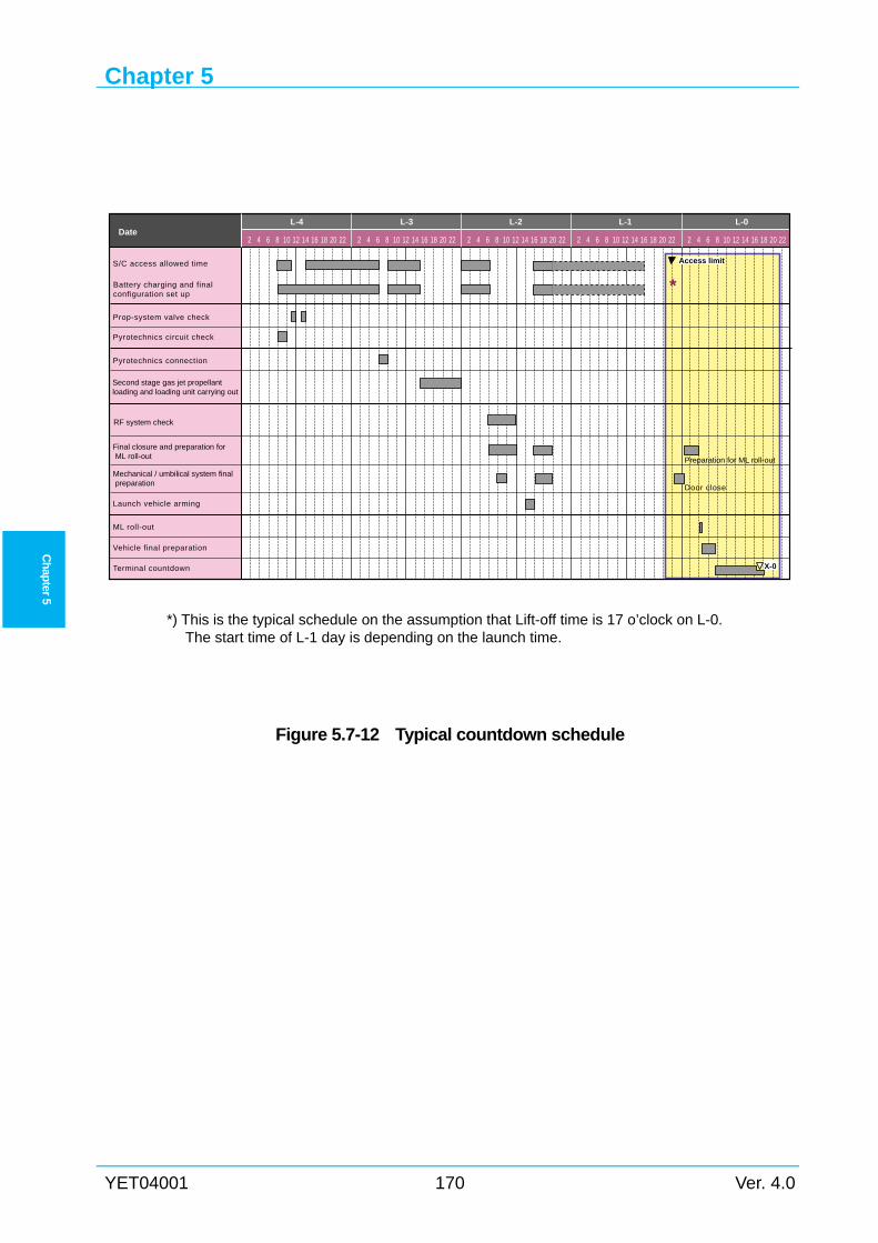
Chapter 5
YET04001 170 Ver. 4.0
Ch
apter 5
*) This is the typical schedule on the assumption that Lift-off time is 17 o’clock on L-0.
The start time of L-1 day is depending on the launch time.
Figure 5.7-12 Typical countdown schedule
L-0
2 4 6 8 10 12 14 16 18 20 22
Pyrotechnics circuit check
Launch vehicle arming
Terminal countdown
Date2 4 6 8 10 12 14 16 18 20 22 2 4 6 8 10 12 14 16 18 20 22 2 4 6 8 10 12 14 16 18 20 22 2 4 6 8 10 12 14 16 18 20 22
L-4 L-3 L-2 L-1
S/C access allowed time
Prop-system valve check
Pyrotechnics connection
ML roll-out
Vehicle final preparation
Second stage gas jet propellantloading and loading unit carrying out
RF system check
Final closure and preparation for ML roll-out
Mechanical / umbilical system final preparation
Battery charging and finalconfiguration set up
Door close
Preparation for ML roll-out
*
X-0
Access limit
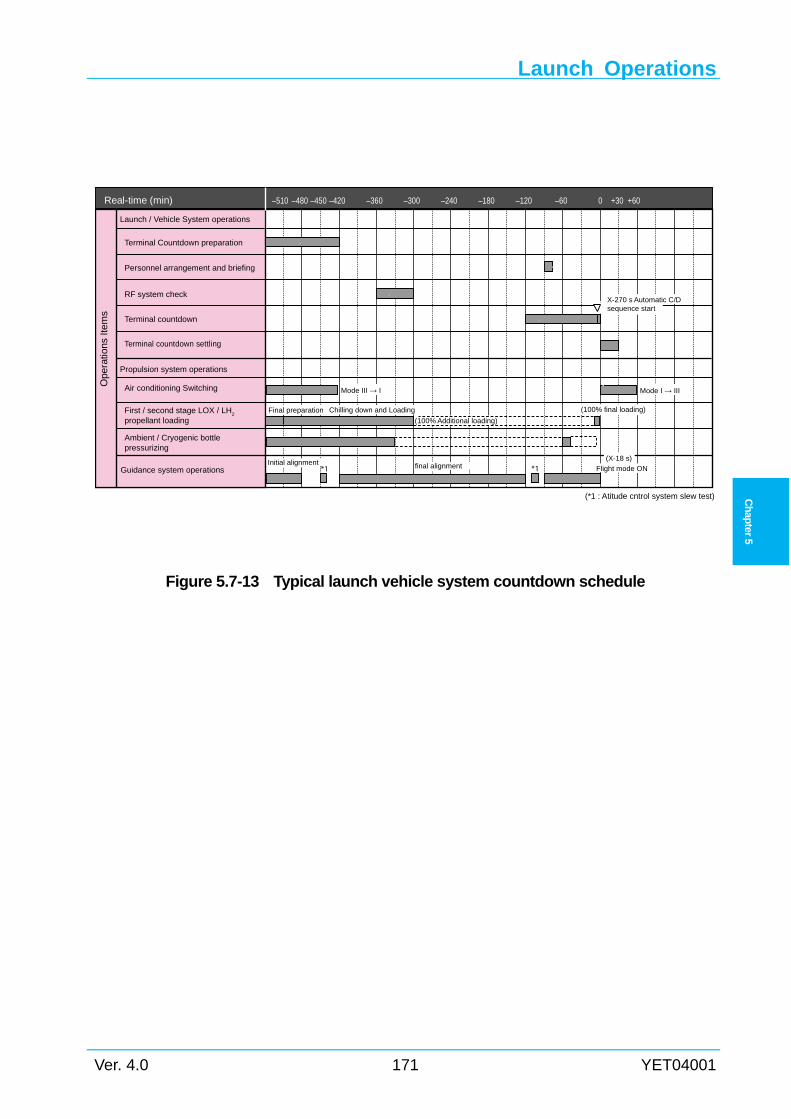
Launch Operations
Ver. 4.0 171 YET04001
Ch
apter 5
Figure 5.7-13 Typical launch vehicle system countdown schedule
Real-time (min) –510 –480 –450 –420 –360 –300 –240 –180 –120 –60 0 +30 +60
Ope
ratio
ns It
ems
Mode III → I
(*1 : Atitude cntrol system slew test)
Initial alignment
Launch / Vehicle System operations
Personnel arrangement and briefing
RF system check
Terminal countdown
Terminal countdown settling
Propulsion system operations
Air conditioning Switching
First / second stage LOX / LH2
propellant loading
Ambient / Cryogenic bottlepressurizing
Guidance system operations
Terminal Countdown preparation
Final preparation Chilling down and Loading
(100% Additional loading)
Flight mode ON*1(X-18 s)
X-270 s Automatic C/Dsequence start
final alignment*1
Mode I → III
(100% final loading)
Chapter 5
YET04001 172 Ver. 4.0
Ch
apter 5
Intentionally blank
Chapter 6
Ver. 4.0 173 YET04001
Ch
apter 6
Chapter 6 INTERFACE MANAGEMENT
6.1 General This chapter describes the spacecraft / H-IIA launch vehicle interface management.
6.1.1 Launch services point of contact The contact point of LSP is described below.
(1) Contract
Space Systems Business Development Department is responsible for the development of a
commercial launch services business and launch services contract management.
(2) Launch services
Space Systems Division is responsible for production of the H-IIA launch vehicle. After the
contract, it becomes a single point of contact with SCO and responsible for the H-IIA Launch
Services.
6.1.2 Interface management document
Document to be submitted by SCO 6.1.2.1SCO is required to submit to LSP the documents shown in Table 6.1-1 which are required for
coordinating the interface between the spacecraft and H-IIA launch vehicle System.
Document to be prepared by LSP 6.1.2.2After the contract, LSP and SCO have technical interchange meetings (TIMs), and the results
of the agreement between SCO and LSP are incorporated in the “Spacecraft / H-IIA Interface
Control Document (ICD)” which specifies details of the interface items.
The ICD is maintained and managed by LSP until launch.
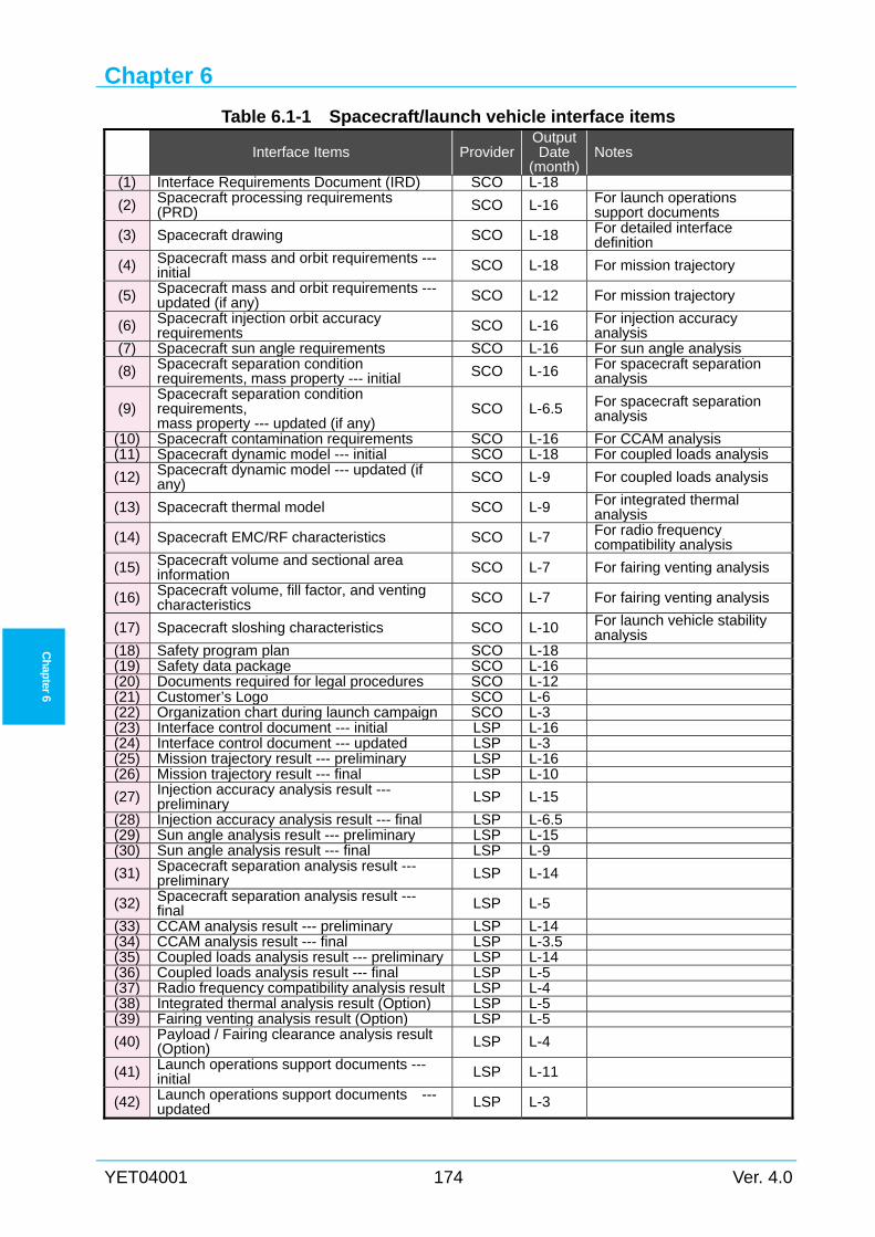
Chapter 6
YET04001 174 Ver. 4.0
Ch
apter 6
Table 6.1-1 Spacecraft/launch vehicle interface items
Interface Items ProviderOutput Date
(month)Notes
(1) Interface Requirements Document (IRD) SCO L-18
(2) Spacecraft processing requirements(PRD) SCO L-16 For launch operations
support documents
(3) Spacecraft drawing SCO L-18 For detailed interface definition
(4) Spacecraft mass and orbit requirements ---initial SCO L-18 For mission trajectory
(5) Spacecraft mass and orbit requirements ---updated (if any) SCO L-12 For mission trajectory
(6) Spacecraft injection orbit accuracy requirements SCO L-16 For injection accuracy
analysis (7) Spacecraft sun angle requirements SCO L-16 For sun angle analysis
(8) Spacecraft separation condition requirements, mass property --- initial SCO L-16 For spacecraft separation
analysis
(9) Spacecraft separation condition requirements, mass property --- updated (if any)
SCO L-6.5 For spacecraft separation analysis
(10) Spacecraft contamination requirements SCO L-16 For CCAM analysis (11) Spacecraft dynamic model --- initial SCO L-18 For coupled loads analysis
(12) Spacecraft dynamic model --- updated (if any) SCO L-9 For coupled loads analysis
(13) Spacecraft thermal model SCO L-9 For integrated thermal analysis
(14) Spacecraft EMC/RF characteristics SCO L-7 For radio frequency compatibility analysis
(15) Spacecraft volume and sectional area information SCO L-7 For fairing venting analysis
(16) Spacecraft volume, fill factor, and venting characteristics SCO L-7 For fairing venting analysis
(17) Spacecraft sloshing characteristics SCO L-10 For launch vehicle stability analysis
(18) Safety program plan SCO L-18(19) Safety data package SCO L-16(20) Documents required for legal procedures SCO L-12(21) Customer’s Logo SCO L-6(22) Organization chart during launch campaign SCO L-3(23) Interface control document --- initial LSP L-16(24) Interface control document --- updated LSP L-3(25) Mission trajectory result --- preliminary LSP L-16(26) Mission trajectory result --- final LSP L-10
(27) Injection accuracy analysis result ---preliminary LSP L-15
(28) Injection accuracy analysis result --- final LSP L-6.5(29) Sun angle analysis result --- preliminary LSP L-15(30) Sun angle analysis result --- final LSP L-9
(31) Spacecraft separation analysis result ---preliminary LSP L-14
(32) Spacecraft separation analysis result ---final LSP L-5
(33) CCAM analysis result --- preliminary LSP L-14(34) CCAM analysis result --- final LSP L-3.5(35) Coupled loads analysis result --- preliminary LSP L-14(36) Coupled loads analysis result --- final LSP L-5(37) Radio frequency compatibility analysis result LSP L-4(38) Integrated thermal analysis result (Option) LSP L-5(39) Fairing venting analysis result (Option) LSP L-5
(40) Payload / Fairing clearance analysis result (Option) LSP L-4
(41) Launch operations support documents ---initial LSP L-11
(42) Launch operations support documents ---updated LSP L-3
Interface Management
Ver. 4.0 175 YET04001
Ch
apter 6
6.2 Interface Coordination with SCO Spacecraft / H-IIA launch vehicle interface coordination is handled by LSP. The results of the
interface coordination are incorporated in the ICD, whenever applicable.
6.2.1 Interface schedule / Interface items The interface schedule is established to define interface tasks including analysis, match mate
test and review meetings. It specifies the time of the tasks implementation and data exchange.
The details will be coordinated at technical interchange meetings (TIMs) for each mission. A
typical interface schedule and interface items for the standard orbit mission are shown in Figure
6.2-1 and Table 6.1-1, respectively.
Note that the schedule and items shown in Figure 6.2-1 and Table 6.1-1 are those for the
standard missions (such as standard GTO or standard SSO) using already developed spacecraft
bus. In case that special orbit injection is required or in case that the spacecraft has some first
flight items, which additional analyses might be needed, then LSP can tailor the schedule based
on the spacecraft requirements and coordination. Also, in case of missions using newly
developed spacecraft bus, early phase of the spacecraft safety review (phase 0, 1, and 2) must be
held separately and total integration period will be longer than that of Figure 6.2-1.
6.2.2 Mission analysis
General 6.2.2.1LSP conducts following mission analyses to confirm that the spacecraft is injected into the
required orbit with the required condition.
(1) Mission trajectory design
(2) Injection accuracy analysis
(3) Sun angle analysis
(4) Spacecraft separation analysis
(5) Contamination and collision avoidance maneuver analysis
(6) Coupled loads analysis
(7) Radio frequency compatibility analysis
(8) Integrated thermal analysis (Option)
(9) Fairing venting analysis (Option)
(10) Payload / Fairing clearance analysis (Option)
Typically, some of these analyses will be conducted two cycles, preliminary and final. The
preliminary analyses are conducted based on the requirements and mathematical models
provided from SCO just after the mission integration kick-off. The final analyses are conducted
based on the updated requirements or condition, and the results are reviewed at the Mission
Analysis Review (MAR).
Chapter 6
YET04001 176 Ver. 4.0
Ch
apter 6
Overview of each analysis 6.2.2.2
6.2.2.2.1 Mission trajectory design The mission trajectory design is conducted to determine the trajectory, and to provide the
major sequence of events and target orbit at spacecraft separation which meet the mission
requirements and constraints of the spacecraft. In this design, the mission requirements from
SCO (orbit requirement, mass properties, sun angle constraints, requirements at spacecraft
separation, etc.), launch vehicle data, and design criteria are used.
6.2.2.2.2 Injection accuracy analysis The injection accuracy analysis is conducted to evaluate the injection orbit error at spacecraft
separation caused by error sources including the vehicle model and inertial sensors, and to
provide the covariance matrix at spacecraft separation, trajectory dispersion, and attitude data for
other analyses. This analysis is based on the mission trajectory.
6.2.2.2.3 Sun angle analysis The sun angle analysis is conducted to provide information on the sun angle historical profile
and eclipse duration in GTO, and to verify sun angle constraint of the spacecraft. This analysis is
based on the mission trajectory.
6.2.2.2.4 Spacecraft separation analysis The spacecraft separation analysis is conducted to analyze the spacecraft pointing error,
angular rate error, and clearance between spacecraft and second stage at separation by analyzing
separation motion of the spacecraft and second stage, based on the latest information on
spacecraft mass properties provided from SCO.
6.2.2.2.5 Contamination and collision avoidance maneuver analysis (CCAM) The contamination and collision avoidance maneuver analysis is conducted to analyze the
relative position between the launch vehicle and the spacecraft after spacecraft separation. This
analysis also supplies information of contamination to which the spacecraft is deposited by the
launch vehicle collision avoidance maneuver after the spacecraft separation.
6.2.2.2.6 Coupled loads analysis (CLA) The CLA is conducted to assess the load imposed on the spacecraft and the relative
displacement from the payload fairing during launch. This analysis uses the spacecraft CLA
model provided from SCO in combination with the vehicle body model. The analysis result will
be supplied to SCO. Even in case that the spacecraft mechanical properties does not comply with
the H-IIA interface condition by this manual description, interface requirements between the
spacecraft and the H-IIA launch vehicle will be tailored by the coordination based on the CLA.
6.2.2.2.7 Radio frequency compatibility analysis The radio frequency compatibility analysis is conducted to verify the RF compatibility based
Interface Management
Ver. 4.0 177 YET04001
Ch
apter 6
on the H-IIA launch vehicle / spacecraft spurious radiation shown in Figure 3.6-1 and 3.6-2.
6.2.2.2.8 Integrated thermal analysis (Option) The integrated thermal analysis is conducted to verify that the spacecraft thermal
environments are within the range specified in the ICD. This analysis uses the thermal
mathematical model provided from SCO and the mission trajectory. This analysis covers thermal
environments from the spacecraft encapsulation into the payload fairing to the spacecraft
separation.
6.2.2.2.9 Fairing venting analysis (Option) Fairing venting analysis is conducted to show time history of the air pressure in the payload
fairing to confirm that the pressure does not cause adverse effect on the spacecraft. This analysis
use spacecraft volume, fill factor, and venting characteristics information.
6.2.2.2.10 Payload / Fairing clearance analysis (Option) Payload/Fairing clearance analysis is conducted to confirm that the clearance between the
spacecraft and payload fairing are greater than zero during flight. This analysis is conducted
when the usable volume is violated.
6.2.3 Interface tests
Match mate test between spacecraft and PLA 6.2.3.1The match mate test of the spacecraft and payload adapter is conducted by LSP using the
flight model payload adapter. The payload adapter or test jigs are prepared and transported by
LSP. Typical timing of the match mate test is as shown in Figure 6.2-1. Details will be
coordinated at TIM.
Umbilical connector disconnection test (Option) 6.2.3.2A disconnection function between the spacecraft umbilical connector and payload fairing
umbilical connector is checked to verify that normal connection and disconnection are possible.
This test is conducted by LSP. A set of the payload fairing connectors (flight model or
equivalent) is transported to SCO facilities, and is subjected to the connection and disconnection
test.
Separation shock test support(Option) 6.2.3.3The separation shock test (option) at spacecraft separation event is conducted by SCO using
the flight model payload adapter or equivalent test model. This test is usually held together with
the spacecraft / payload adapter match mate test.
Details will be coordinated at TIM.
Chapter 6
YET04001 178 Ver. 4.0
Ch
apter 6
6.2.4 Mission modifications
Payload fairing mission modification 6.2.4.1The following items can be installed on the payload fairing as requested by SCO. Details are
described in Section 4.5.4.
(1) Access doors
(2) Umbilical connectors
(3) Radio transparent window
(4) Internal antenna
(5) External antenna
(6) Internal and external antennas
(7) Acoustic blankets
(8) Independent air conditioner (air conditioned inlet, partition wall and relief valve)
Figure 6.2-1 illustrates the interface schedule for this mission modification.
Payload adapter mission modification 6.2.4.2The following items can be installed on the payload adapter as requested by SCO.
(1) The number of separation springs
(2) Umbilical connectors
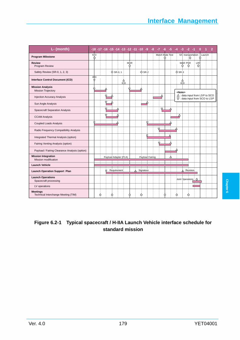
Interface Management
Ver. 4.0 179 YET04001
Ch
apter 6
Figure 6.2-1 Typical spacecraft / H-IIA Launch Vehicle interface schedule for
standard mission
K/O Match Mate Test S/C transportation Launch
IRD
ICD ICD
Payload Adapter (PLA) Payload Fairing
SignatureRequirement Revision
Joint Operations
SR-0, 1 SR-2 SR-3
MDR MAR PSR LRR
Program Milestone
L- (month) -18 -17 -16 -15 -14 -13 -12 -11 -10 -9 -8 -7 -6 -5 -4 -3 -2 -1 0 1 2
Review
Interface Control Document (ICD)
Program Review
Mission AnalysisMission Trajectory
Mission Integration
Launch Vehicle
Launch Operation Support Plan
Launch Operations
Mission modification
MeetingsTechnical Interchange Meeting (TIM)
Spacecraft processing
LV operations
Injection Accuracy Analysis
CCAM Analysis
Spacecraft Separation Analysis
Sun Angle Analysis
Coupled Loads Analysis
Integrated Thermal Analysis (option)
Radio Frequency Compatibility Analysis
Fairing Venting Analysis (option)
Payload / Fairing Clearance Analysis (option)
Safety Review (SR-0, 1, 2, 3)
<Note> : data input from LSP to SCO : data input from SCO to LSP
Chapter 6
YET04001 180 Ver. 4.0
Ch
apter 6
6.3 Spacecraft / H-IIA Interface Control
6.3.1 Interface control document The “Spacecraft / H-IIA Interface Control Document (ICD)” related to launch capability,
interface restrictions and launch operations are created and maintained through TIMs held as
required in the spacecraft design, fabrication and test phases, thereby clarifying the requirements
and characteristics inherent to each mission.
Table 6.3-1 shows an example of contents of the ICD.
6.3.2 Coordination items and timing The mission integration schedule is prepared by LSP according to results of coordination with
SCO.
6.3.3 Launch Operations Interface Control Focusing on spacecraft processing and SCO/LSP joint operations (phase 3 activities), launch
operations support documents are created and maintained by LSP. Table 6.3-2 shows contents of
the launch operations support documents.
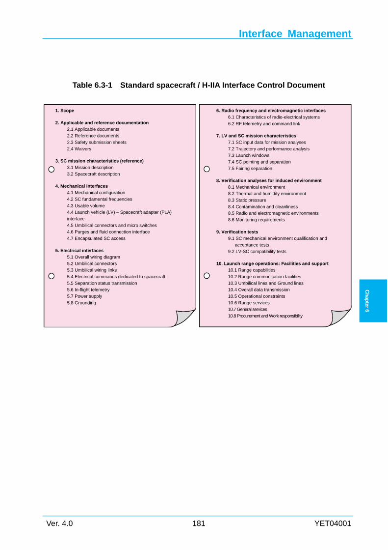
Interface Management
Ver. 4.0 181 YET04001
Ch
apter 6
Table 6.3-1 Standard spacecraft / H-IIA Interface Control Document
1. Scope
2. Applicable and reference documentation
2.1 Applicable documents
2.2 Reference documents
2.3 Safety submission sheets
2.4 Waivers
3. SC mission characteristics (reference)
3.1 Mission description
3.2 Spacecraft description
4. Mechanical Interfaces
4.1 Mechanical configuration
4.2 SC fundamental frequencies
4.3 Usable volume
4.4 Launch vehicle (LV) – Spacecraft adapter (PLA)
interface
4.5 Umbilical connectors and micro switches
4.6 Purges and fluid connection interface
4.7 Encapsulated SC access
5. Electrical interfaces
5.1 Overall wiring diagram
5.2 Umbilical connectors
5.3 Umbilical wiring links
5.4 Electrical commands dedicated to spacecraft
5.5 Separation status transmission
5.6 In-flight telemetry
5.7 Power supply
5.8 Grounding
6. Radio frequency and electromagnetic interfaces
6.1 Characteristics of radio-electrical systems
6.2 RF telemetry and command link
7. LV and SC mission characteristics
7.1 SC input data for mission analyses
7.2 Trajectory and performance analysis
7.3 Launch windows
7.4 SC pointing and separation
7.5 Fairing separation
8. Verification analyses for induced environment
8.1 Mechanical environment
8.2 Thermal and humidity environment
8.3 Static pressure
8.4 Contamination and cleanliness
8.5 Radio and electromagnetic environments
8.6 Monitoring requirements
9. Verification tests
9.1 SC mechanical environment qualification and
acceptance tests
9.2 LV-SC compatibility tests
10. Launch range operations: Facilities and support
10.1 Range capabilities
10.2 Range communication facilities
10.3 Umbilical lines and Ground lines
10.4 Overall data transmission
10.5 Operational constraints
10.6 Range services
10.7 General services
10.8 Procurement and Work responsibility
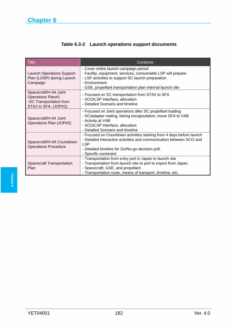
Chapter 6
YET04001 182 Ver. 4.0
Ch
apter 6
Table 6.3-2 Launch operations support documents
Title Contents
Launch Operations Support Plan (LOSP) during Launch Campaign
- Cover entire launch campaign period - Facility, equipment, services, consumable LSP will prepare - LSP activities to support SC launch preparation - Environment - GSE, propellant transportation plan internal launch site
Spacecraft/H-IIA Joint Operations Plan#1 -SC Transportation from STA2 to SFA- (JOP#1)
- Focused on SC transportation from STA2 to SFA - SCO/LSP Interface, allocation - Detailed Scenario and timeline
Spacecraft/H-IIA Joint Operations Plan (JOP#2)
- Focused on Joint operations after SC propellant loading - SC/adapter mating, fairing encapsulation, move SFA to VAB - Activity at VAB - SCO/LSP Interface, allocation - Detailed Scenario and timeline
Spacecraft/H-IIA Countdown Operations Procedure
- Focused on Countdown activities starting from 4 days before launch - Detailed interactive activities and communication between SCO and LSP - Detailed timeline for Go/No-go decision poll. - Specific constraint
Spacecraft Transportation Plan
- Transportation from entry port in Japan to launch site - Transportation from launch site to port to export from Japan. - Spacecraft, GSE, and propellant - Transportation route, means of transport, timeline, etc.
Interface Management
Ver. 4.0 183 YET04001
Ch
apter 6
6.4 Safety Reviews
6.4.1 Payload safety requirements
The spacecraft design and spacecraft processing at the launch campaigns are required to meet
requirements of“JMR-002: Launch Vehicle Payload Safety Standard” and “JERG-1-007: Safety
Regulation for Launch Site Operation/Flight Control Operation”. SCO should enforce the safety
program according to requirements of JMR-002. For more information regarding safety
requirement document, please contact LSP.
6.4.2 Safety program plan SCO is required to submit “Safety Program Plan“ to LSP according to JMR-002.
LSP establishes “Payload Safety Program Plan” based on the Safety Program Plan of SCO,
and submits it to JAXA. LSP coordinates with JAXA to obtain the approval of JAXA safety
authorities.
6.4.3 Safety review data package SCO is required to submit the spacecraft safety data package to LSP according to JMR-002 for
each safety review phase.
LSP pre-reviews the data package to ensure compliance with the safety requirements of
JMR-002 and JERG-1-007 from the view point of integrated safety assessment between
spacecraft and launch vehicle, and submits it to the JAXA safety review for approval.
JAXA holds safety review of this safety data package, and informs LSP and SCO of review
results, and requires corrective actions if necessary.
Chapter 6
YET04001 184 Ver. 4.0
Ch
apter 6
6.5 Reviews and Other Meetings This section describes the reviews and other meetings required to launch the spacecraft and
launch vehicle.
6.5.1 Reviews and Meetings before launch campaign
Technical Interchange Meeting (TIM) 6.5.1.1Technical interchange meeting is to coordinate technical interface matters. This meeting is
held whenever required.
Program Management Meeting (PMM) 6.5.1.2Program management meeting is to coordinate schedule and program promotion matters. This
meeting is held whenever required.
Mission Modification Design Review (MDR) 6.5.1.3Mission modification design reviews are conducted at major program milestones for both the
generic launch vehicle and mission specific design/analysis, including the payload adapter and
separation system. Mission specific PDRs and CDRs are conducted for each program, if
necessary. SCO is expected to participate in these reviews to ensure that the design meets SCO
requirements.
Mission Analyses Review (MAR) 6.5.1.4Mission analyses review is to review the result of each mission analysis, defined in Section
6.2.2, shows the launch vehicle mission plan and performance meet the mission requirements
defined in the ICD. Typically, this review is held at LSP facilities, and also launch vehicle
preparation status is reported.
6.5.2 Reviews and Meetings on launch campaign
Launch Site Readiness Meeting (LSRM) 6.5.2.1Launch site readiness meeting is to introduce the following status before the spacecraft is
shipped to launch site. If SCO does not attend this meeting, the result is informed to SCO.
(1) Launch site readiness status for SCO activities
(2) Launch site readiness status for LSP activities and launch vehicle manufacturing status
Launch Site Daily Meeting (LSDM) 6.5.2.2During the launch campaign, launch site daily meeting is held every morning before starting
the spacecraft activities of the day in order to share SC/LV status such as:
(1) Planned support activities by LSP and any constraint for the spacecraft activities.
(2) SCO and LSP activities’ status, especially for any unexpected event that might affect the
planned activities and/or schedule.
Interface Management
Ver. 4.0 185 YET04001
Ch
apter 6
Launch Vehicle Readiness Review (LVRR) 6.5.2.3Launch vehicle readiness review is to ensure that launch vehicle and GSE preparations are
ready for countdown operations. The review is held just before the LRR to ensure the verified
results are reported in the LRR. If SCO does not attend this meeting, the result is informed to
SCO.
Range Safety Readiness Review (RSRR) 6.5.2.4Range safety readiness review is to ensure that the flight safety, ground safety, and range
safety are established, and preparations for telemetry, tracking/communication are completed.
This review is held by JAXA and typically attended by LSP personnel. The result is informed to
SCO.
Spacecraft Readiness Review (SCRR) 6.5.2.5Spacecraft readiness review is to ensure that spacecraft and GSE preparations are ready for
countdown operations. This review is held by SCO and typically attended by LSP personnel.
This review is held just before encapsulation of the spacecraft into the payload fairing to ensure
that the verified results are reported in the LRR.
Launch Readiness Review (LRR) 6.5.2.6Launch readiness review is to confirm that all organizations involved in the launch are ready
to start countdown operations. Each organization reports the current progress of preparation and
conclusion of the review meeting. Based on the launch director’s approval after this review, the
countdown operations are started.
6.5.3 Safety review The safety review is described in Section 6.4.
6.5.4 Post-flight Meeting (PFM) Post-flight meeting is to evaluate the post-flight analysis data; injection data, orbital tracking
operations report, launch evaluation report. Also, the “lessons learned” about the launch vehicle,
spacecraft processing support during launch campaign are discussed, and appropriate actions will
be identified for the next launch program.
Chapter 6
YET04001 186 Ver. 4.0
Ch
apter 6
Intentionally blank
Appendix 1
Ver. 4.0 187 YET04001
Ap
pen
dix 1
Appendix 1 HISTORY OF NASDA LAUNCH VEHICLES A1
A1.1 General N-I, N-II, H-I and H-II launch vehicles had been developed since early seventies when
NASDA, currently JAXA, started the space development. Many organizations related to H-IIA
Launch Services had contributed to these launch vehicle’s development. Abstracts of the H-I and
H-II Launch Vehicles are described in the following sections.
Table A1-1 summarizes launch results of NASDA launch vehicles.
Figure A1-1 shows configuration of NASDA launch vehicles.
A1.2 Abstract of The H-I Launch Vehicle NASDA had used the H-I Launch Vehicle as the main launch vehicle since 1986. It had
Delta-based first stage (the MB-3 engine), which was basically same as the N-I and N-II rockets
with strap-on boosters (SOBs), and a domestically developed LOX / LH2 second stage
propulsion system (the LE-5 engine). Up to 1992, nine payloads (geostationary meteorological
satellites, communications satellites, and TV broadcasting satellites) had all been successfully
launched by the H-I from Osaki Range of the Tanegashima Space Center (TNSC).
A1.3 Abstract of The H-II Launch Vehicle The H-II Launch Vehicle was designed to serve as NASDA’s main space transportation system
in the 1990s to meet the demands for large satellites launching at lower cost yet maintaining a
high degree of reliability. It was capable of sending a 4-ton class payload into geostationary
transfer orbit.
The H-II was a two-stage launch vehicle equipped with two large scale solid rocket boosters
(SRBs) for thrust augmentation. A new liquid propellant (liquid hydrogen / liquid oxygen)
engine, called LE-7, was developed for the first stage. The LE-7 was a high performance engine
adopting a high-pressure staged-combustion cycle. The LE-5A engine, which was the improved
version of the LE-5 engine developed for the H-I, was used in the second stage. A strapped-down
inertial guidance system utilizing ring laser gyros was employed for the guidance system. The
standard payload fairing was 4 meters in diameter and 12 meters in length so that it could
encapsulate a payload up to 3.7 meters in diameter and 10 meters in length.
Besides carrying satellites into low earth orbit and geostationary transfer orbit, the H-II was
capable of launching planetary probes. The H-II was launched from Yoshinobu launch complex
at the TNSC.
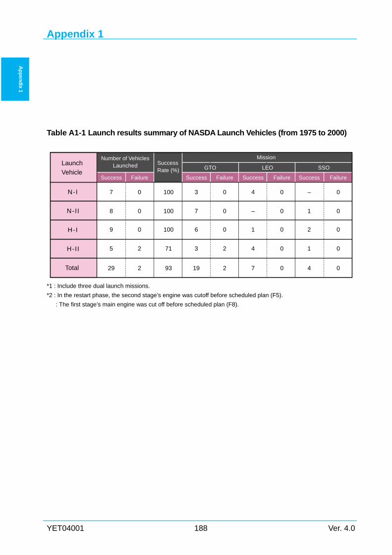
Appendix 1
YET04001 188 Ver. 4.0
Ap
pen
dix 1
Table A1-1 Launch results summary of NASDA Launch Vehicles (from 1975 to 2000)
*1 : Include three dual launch missions.
*2 : In the restart phase, the second stage’s engine was cutoff before scheduled plan (F5).
: The first stage’s main engine was cut off before scheduled plan (F8).
Launch
Vehicle
Number of VehiclesLaunched Success
Rate (%)
Mission
GTO LEO SSO
Success Failure Success Failure Success Failure Success Failure
7 0 100 3 0 4 0 – 0
8 0 100 7 0 – 0 1 0
9 0 100 6 0 1 0 2 0
5 2 71 3 2 4 0 1 0
N-I
N-II
H-I
H-II
Total 29 2 93 19 2 7 0 4 0
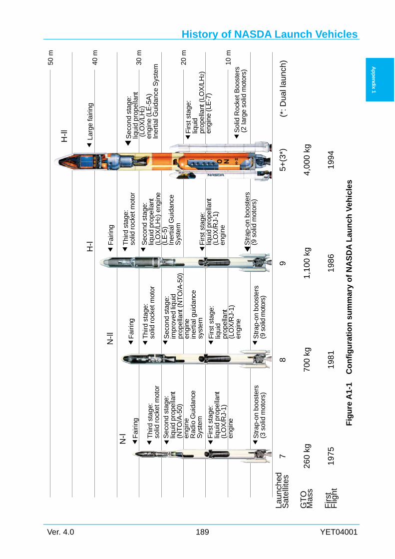
History of NASDA Launch Vehicles
Ver. 4.0 189 YET04001
Ap
pen
dix 1
Fig
ure
A1-
1 C
on
fig
ura
tio
n s
um
mar
y o
f N
AS
DA
Lau
nch
Veh
icle
s
50 m
40 m
30 m
20 m
10 m
H-l
l
Larg
e fa
iring
Sec
ond
stag
e:liq
uid
prop
ella
nt(L
OX
/LH
2)en
gine
(LE
-5A
)In
ertia
l Gui
danc
e S
yste
m
Firs
tsta
ge:
liqui
dpr
opel
lant
(LO
X/L
H2)
engi
ne(L
E-7
)
Sol
idR
ocke
t Boo
ster
s(2
Iarg
e so
lidm
otor
s)
Fai
ring
H-l T
hird
sta
ge:
solid
rock
etm
otor
Firs
t sta
ge:
liqui
dpr
opel
lant
(LO
X/R
J-1)
engi
ne
N-l
l
Fai
ring
Thi
rd s
tage
:so
lidro
cket
mot
or
Sec
ond
stag
e:im
prov
edliq
uid
prop
ella
nt(N
TO
/A-5
0)en
gine
iner
tialg
uida
nce
syst
em
Firs
t sta
ge:
liqui
dpr
opel
lant
(LO
X/R
J-1)
engi
ne
Str
ap-o
nbo
oste
rs(9
solid
mot
ors)
N-l F
airin
g
Thi
rdst
age:
solid
rock
etm
otor
Sec
ond
stag
e:liq
uid
prop
ella
nt(N
TO
/A-5
0)en
gine
Rad
io G
uida
nce
Sys
tem
Firs
tsta
ge:
liqui
dpr
opel
lant
(LO
X/R
J-1)
engi
ne
Str
ap-o
nbo
oste
rs(3
sol
idm
otor
s)
7
26
0 k
g
19
75
8
70
0 k
g
19
81
9
1,1
00
kg
19
86
La
un
ched
Sa
telli
tes
GT
OM
ass
Sec
ond
stag
e:liq
uid
prop
ella
nt(L
OX
/LH
2)en
gine
(LE
-5)
Iner
tial G
uida
nce
Sys
tem
Str
ap-o
nbo
oste
rs(9
sol
idm
otor
s)
5+
(3*)
4,0
00
kg
19
94
Fir
stF
ligh
t
(*: D
ua
l la
un
ch)
Appendix 1
YET04001 190 Ver. 4.0
Ap
pen
dix 1
Intentionally blank
Appendix 2
Ver. 4.0 191 YET04001
Ap
pen
dix 2
Appendix 2 SPACECRAFT DATA SHEET
Spacecraft organization having interest to launch its spacecraft using the H-IIA launch vehicle
is expected to inform of the spacecraft requirements, by completing the spacecraft data sheet in
the following pages and return it to the address below.
The information from the spacecraft organization will be used for LSP’s evaluation of
compatibility between the spacecraft and H-IIA launch system, or be used to establish the basis
of the spacecraft/ H-IIA interface agreement.
Please note that not all the items shown in the following data sheet and not all the answers
from the spacecraft organization are within the scope of the standard MHI Launch Services.
LSP will treat the information as spacecraft organization’s proprietary information, and will
not disclose any part of them outside LSP without written approval.
Space Systems Business Development Department
Business Development Division
Integrated Defense & Space Systems
Mitsubishi Heavy Industries, Ltd.
16-5, KONAN, 2-CHOME, MINATO-KU, TOKYO, 108-8215 JAPAN
Telephone + 81-3-6716-4342
Fax + 81-3-6716-5869
http://h2a.mhi.co.jp/en/index.html
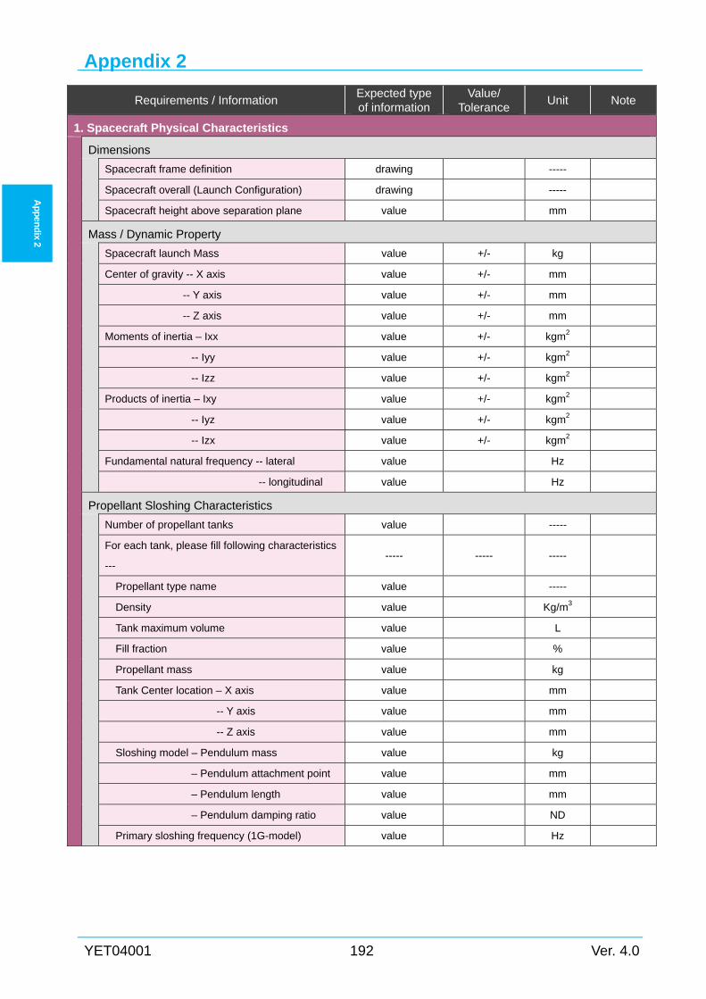
Appendix 2
YET04001 192 Ver. 4.0
Ap
pen
dix 2
Requirements / Information Expected type of information
Value/ Tolerance
Unit Note
1. Spacecraft Physical Characteristics
Dimensions
Spacecraft frame definition drawing -----
Spacecraft overall (Launch Configuration) drawing -----
Spacecraft height above separation plane value mm
Mass / Dynamic Property
Spacecraft launch Mass value +/- kg
Center of gravity -- X axis value +/- mm
-- Y axis value +/- mm
-- Z axis value +/- mm
Moments of inertia – Ixx value +/- kgm2
-- Iyy value +/- kgm2
-- Izz value +/- kgm2
Products of inertia – Ixy value +/- kgm2
-- Iyz value +/- kgm2
-- Izx value +/- kgm2
Fundamental natural frequency -- lateral value Hz
-- longitudinal value Hz
Propellant Sloshing Characteristics
Number of propellant tanks value -----
For each tank, please fill following characteristics
--- ----- ----- -----
Propellant type name value -----
Density value Kg/m3
Tank maximum volume value L
Fill fraction value %
Propellant mass value kg
Tank Center location – X axis value mm
-- Y axis value mm
-- Z axis value mm
Sloshing model – Pendulum mass value kg
– Pendulum attachment point value mm
– Pendulum length value mm
– Pendulum damping ratio value ND
Primary sloshing frequency (1G-model) value Hz
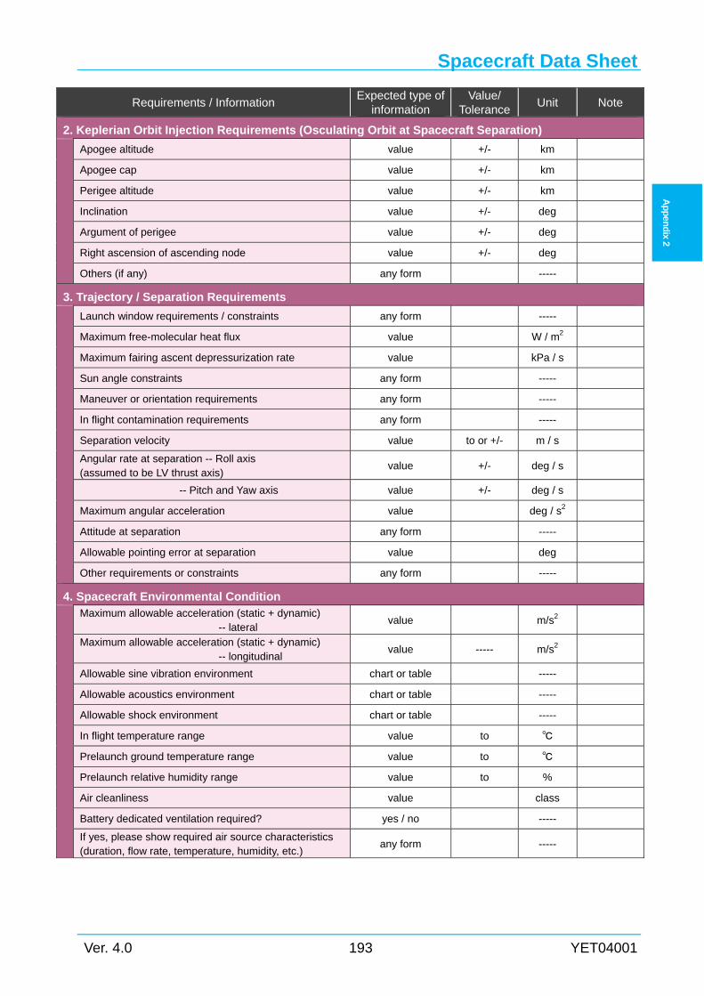
Spacecraft Data Sheet
Ver. 4.0 193 YET04001
Ap
pen
dix 2
Requirements / Information Expected type of
information Value/
Tolerance Unit Note
2. Keplerian Orbit Injection Requirements (Osculating Orbit at Spacecraft Separation)
Apogee altitude value +/- km
Apogee cap value +/- km
Perigee altitude value +/- km
Inclination value +/- deg
Argument of perigee value +/- deg
Right ascension of ascending node value +/- deg
Others (if any) any form -----
3. Trajectory / Separation Requirements
Launch window requirements / constraints any form -----
Maximum free-molecular heat flux value W / m2
Maximum fairing ascent depressurization rate value kPa / s
Sun angle constraints any form -----
Maneuver or orientation requirements any form -----
In flight contamination requirements any form -----
Separation velocity value to or +/- m / s
Angular rate at separation -- Roll axis (assumed to be LV thrust axis)
value +/- deg / s
-- Pitch and Yaw axis value +/- deg / s
Maximum angular acceleration value deg / s2
Attitude at separation any form -----
Allowable pointing error at separation value deg
Other requirements or constraints any form -----
4. Spacecraft Environmental Condition
Maximum allowable acceleration (static + dynamic) -- lateral
value m/s2
Maximum allowable acceleration (static + dynamic) -- longitudinal
value ----- m/s2
Allowable sine vibration environment chart or table -----
Allowable acoustics environment chart or table -----
Allowable shock environment chart or table -----
In flight temperature range value to
Prelaunch ground temperature range value to
Prelaunch relative humidity range value to %
Air cleanliness value class
Battery dedicated ventilation required? yes / no -----
If yes, please show required air source characteristics (duration, flow rate, temperature, humidity, etc.)
any form -----
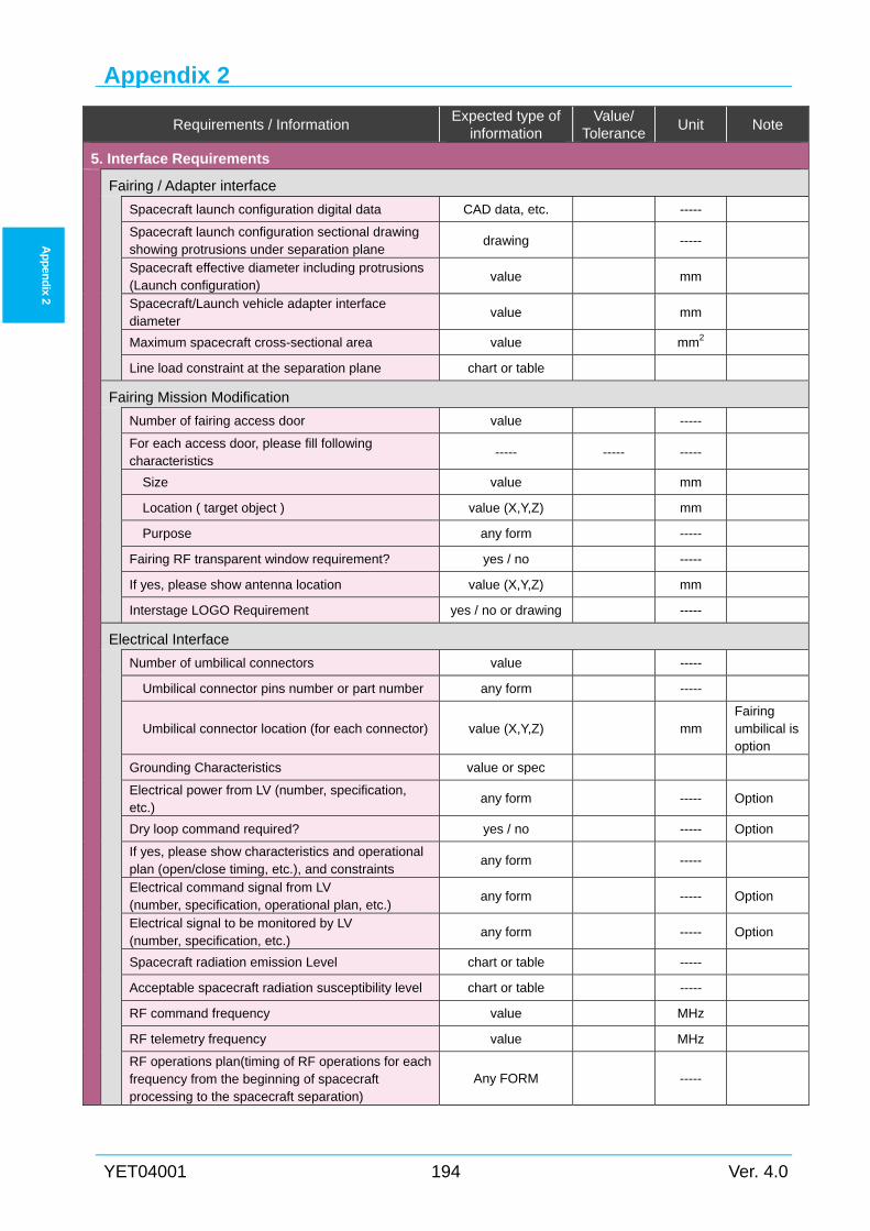
Appendix 2
YET04001 194 Ver. 4.0
Ap
pen
dix 2
Requirements / Information Expected type of
information Value/
Tolerance Unit Note
5. Interface Requirements
Fairing / Adapter interface
Spacecraft launch configuration digital data CAD data, etc. -----
Spacecraft launch configuration sectional drawing showing protrusions under separation plane
drawing -----
Spacecraft effective diameter including protrusions (Launch configuration)
value mm
Spacecraft/Launch vehicle adapter interface diameter
value mm
Maximum spacecraft cross-sectional area value mm2
Line load constraint at the separation plane chart or table
Fairing Mission Modification
Number of fairing access door value -----
For each access door, please fill following characteristics
----- ----- -----
Size value mm
Location ( target object ) value (X,Y,Z) mm
Purpose any form -----
Fairing RF transparent window requirement? yes / no -----
If yes, please show antenna location value (X,Y,Z) mm
Interstage LOGO Requirement yes / no or drawing -----
Electrical Interface
Number of umbilical connectors value -----
Umbilical connector pins number or part number any form -----
Umbilical connector location (for each connector) value (X,Y,Z) mm Fairing umbilical is option
Grounding Characteristics value or spec
Electrical power from LV (number, specification, etc.)
any form ----- Option
Dry loop command required? yes / no ----- Option
If yes, please show characteristics and operational plan (open/close timing, etc.), and constraints
any form -----
Electrical command signal from LV (number, specification, operational plan, etc.)
any form ----- Option
Electrical signal to be monitored by LV (number, specification, etc.)
any form ----- Option
Spacecraft radiation emission Level chart or table -----
Acceptable spacecraft radiation susceptibility level chart or table -----
RF command frequency value MHz
RF telemetry frequency value MHz
RF operations plan(timing of RF operations for each frequency from the beginning of spacecraft processing to the spacecraft separation)
Any FORM -----
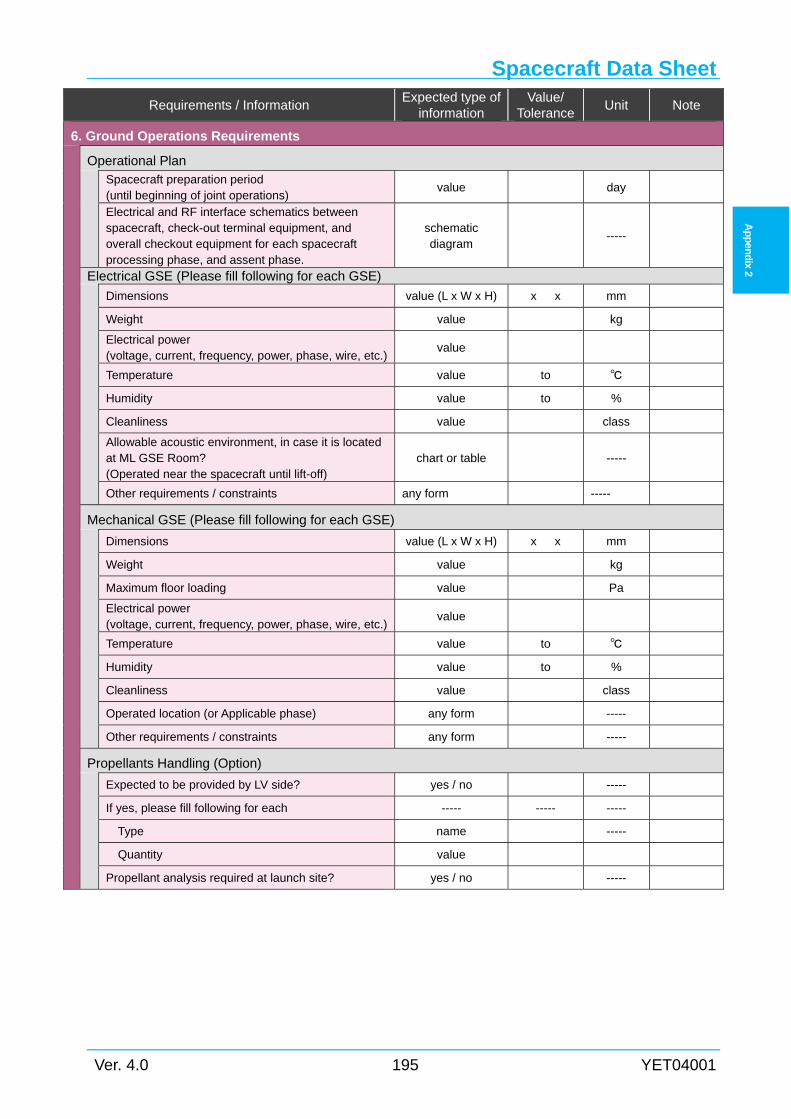
Spacecraft Data Sheet
Ver. 4.0 195 YET04001
Ap
pen
dix 2
Requirements / Information Expected type of
information Value/
Tolerance Unit Note
6. Ground Operations Requirements
Operational Plan
Spacecraft preparation period (until beginning of joint operations)
value day
Electrical and RF interface schematics between spacecraft, check-out terminal equipment, and overall checkout equipment for each spacecraft processing phase, and assent phase.
schematic diagram
-----
Electrical GSE (Please fill following for each GSE)
Dimensions value (L x W x H) x x mm
Weight value kg
Electrical power (voltage, current, frequency, power, phase, wire, etc.)
value
Temperature value to
Humidity value to %
Cleanliness value class
Allowable acoustic environment, in case it is located at ML GSE Room? (Operated near the spacecraft until lift-off)
chart or table -----
Other requirements / constraints any form -----
Mechanical GSE (Please fill following for each GSE)
Dimensions value (L x W x H) x x mm
Weight value kg
Maximum floor loading value Pa
Electrical power (voltage, current, frequency, power, phase, wire, etc.)
value
Temperature value to
Humidity value to %
Cleanliness value class
Operated location (or Applicable phase) any form -----
Other requirements / constraints any form -----
Propellants Handling (Option)
Expected to be provided by LV side? yes / no -----
If yes, please fill following for each ----- ----- -----
Type name -----
Quantity value
Propellant analysis required at launch site? yes / no -----
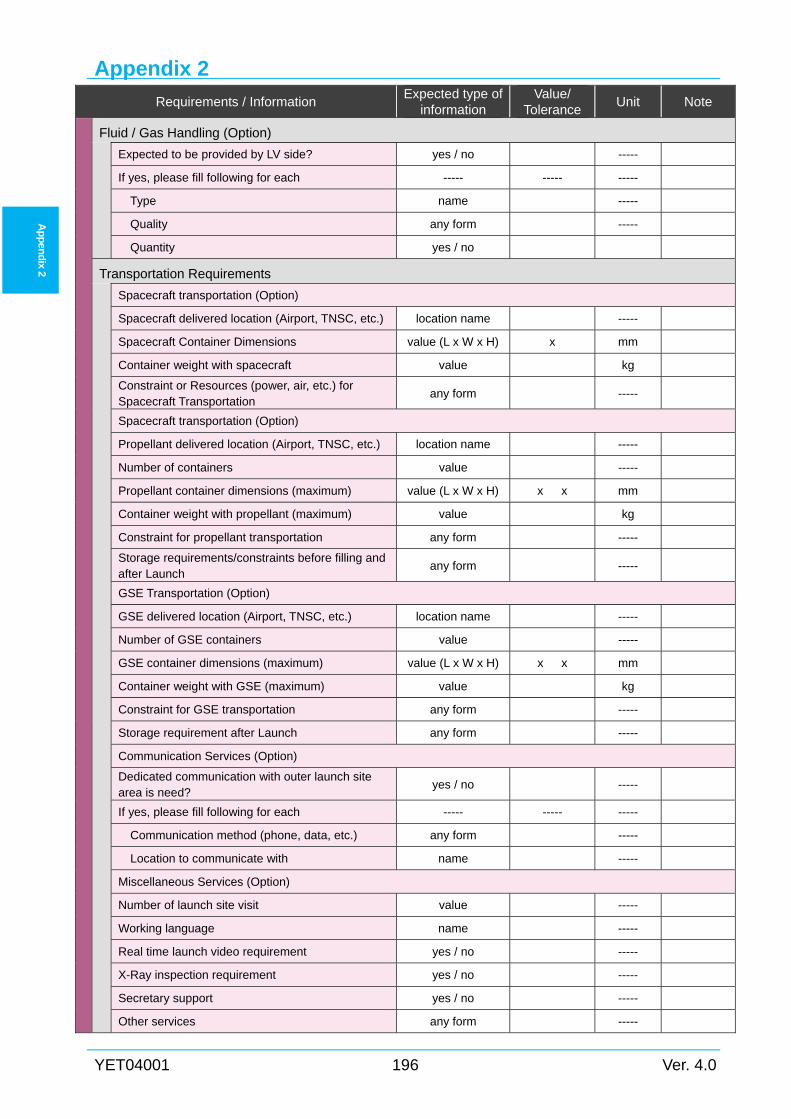
Appendix 2
YET04001 196 Ver. 4.0
Ap
pen
dix 2
Requirements / Information Expected type of
information Value/
Tolerance Unit Note
Fluid / Gas Handling (Option)
Expected to be provided by LV side? yes / no -----
If yes, please fill following for each ----- ----- -----
Type name -----
Quality any form -----
Quantity yes / no
Transportation Requirements
Spacecraft transportation (Option)
Spacecraft delivered location (Airport, TNSC, etc.) location name -----
Spacecraft Container Dimensions value (L x W x H) x mm
Container weight with spacecraft value kg
Constraint or Resources (power, air, etc.) for Spacecraft Transportation
any form -----
Spacecraft transportation (Option)
Propellant delivered location (Airport, TNSC, etc.) location name -----
Number of containers value -----
Propellant container dimensions (maximum) value (L x W x H) x x mm
Container weight with propellant (maximum) value kg
Constraint for propellant transportation any form -----
Storage requirements/constraints before filling andafter Launch
any form -----
GSE Transportation (Option)
GSE delivered location (Airport, TNSC, etc.) location name -----
Number of GSE containers value -----
GSE container dimensions (maximum) value (L x W x H) x x mm
Container weight with GSE (maximum) value kg
Constraint for GSE transportation any form -----
Storage requirement after Launch any form -----
Communication Services (Option)
Dedicated communication with outer launch site area is need?
yes / no -----
If yes, please fill following for each ----- ----- -----
Communication method (phone, data, etc.) any form -----
Location to communicate with name -----
Miscellaneous Services (Option)
Number of launch site visit value -----
Working language name -----
Real time launch video requirement yes / no -----
X-Ray inspection requirement yes / no -----
Secretary support yes / no -----
Other services any form -----
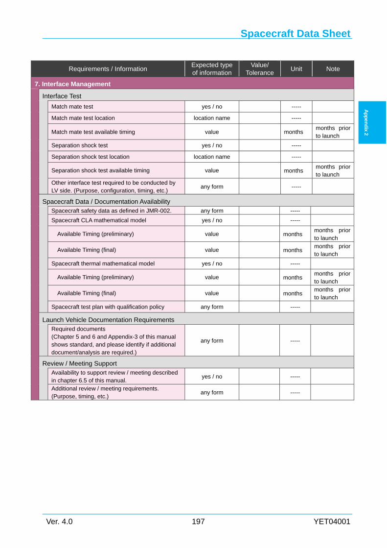
Spacecraft Data Sheet
Ver. 4.0 197 YET04001
Ap
pen
dix 2
Requirements / Information Expected type of information
Value/ Tolerance
Unit Note
7. Interface Management
Interface Test
Match mate test yes / no -----
Match mate test location location name -----
Match mate test available timing value months months prior to launch
Separation shock test yes / no -----
Separation shock test location location name -----
Separation shock test available timing value months months prior to launch
Other interface test required to be conducted by LV side. (Purpose, configuration, timing, etc.)
any form -----
Spacecraft Data / Documentation Availability
Spacecraft safety data as defined in JMR-002. any form -----
Spacecraft CLA mathematical model yes / no -----
Available Timing (preliminary) value months months prior to launch
Available Timing (final) value months months prior to launch
Spacecraft thermal mathematical model yes / no -----
Available Timing (preliminary) value months months prior to launch
Available Timing (final) value months months prior to launch
Spacecraft test plan with qualification policy any form -----
Launch Vehicle Documentation Requirements
Required documents (Chapter 5 and 6 and Appendix-3 of this manual shows standard, and please identify if additional document/analysis are required.)
any form -----
Review / Meeting Support
Availability to support review / meeting described in chapter 6.5 of this manual.
yes / no -----
Additional review / meeting requirements. (Purpose, timing, etc.)
any form -----
Appendix 2
YET04001 198 Ver. 4.0
Ap
pen
dix 2
Intentionally blank
Appendix 3
Ver. 4.0 199 YET04001
Ap
pen
dix 3
Appendix 3 STANDARD SERVICES & OPTIONS
General A3.1
This chapter describes standard and optional services. Appendix 3.2 to Appendix 3.6
describes standard services and Appendix 3.7 describes optional services.
Mission Management A3.2
Mission integration (General Process) A3.2.1
LSP will manage overall activities as follows:
(1) Management of mission integration (schedule control, documentation, obtaining
permissions from domestic authorities.)
(2) Management of Spacecraft/Launch Vehicle integration such as, but not limited to
interface control, mission analyses, launch vehicle production, develop documents, etc.
(3) Management of launch site support service at TNSC (preparation/operations of the launch
site facilities, safety/security management, communication device arrangements, launch
operations assist, logistics support)
The integration of the spacecraft and launch vehicle will be in accordance with documents as
described in Appendix 3.2.2 and technical meeting and review as described in Appendix 3.3.5.
Documentation A3.2.2
Interface Documents A3.2.2.1
LSP will develop and maintain following document and provide to SCO.
(1) Mission Integration Schedule (MIS)
(2) Interface Control Document(ICD)
(3) Mission Analysis Report
(4) Safety Submission Responses
(5) Launch site Operation Support Plan (LOSP)
(6) Joint Operation Plan(JOP)
(7) Count down Plan
(8) Injection Data
(9) Post Flight Analysis Report
(10) Transportation Logistics Plan from first port of entry to/from launch site (for overseas
Appendix 3
YET04001 200 Ver. 4.0
Ap
pen
dix 3
customer)
Status Report A3.2.2.2
LSP will develop following status report periodically to SCO.
(1) Quarterly Report
Quarterly report includes program status, issues such as concern to the launch schedule,
major non-conformances, and flight anomalies that apply design changes.
Licenses /Permissions A3.2.3
LSP will support customer to obtain approval and permission from Japanese government so
that SCO ships the spacecraft and associated equipment to Japan, performs launch preparation at
the launch site.
(1) Obtain license for RF use (for both domestic and overseas customers)
In case that SCO plans radio frequency emission at the launch site, approval from the
Japanese government is required. LSP will obtain the approval for SCO.
(2) Obtain certificate for JAXA High-pressure Gas Standard for spacecraft flight system (for
overseas customer)
Spacecraft flight subsystems which accommodate high pressure gas (more than 1MPa)
shall comply with JAXA standard, JERG-0-001, and need to obtain certificate from JAXA.
LSP will obtain the certificate using data package provided by SCO.
(3) High-pressure gas ground support equipment (for overseas customer)
Any ground support equipment handling high pressure gas, more than 1MPa, such as
propellant tank pressurization GSE, shall comply with specifications defined by Japanese
law. LSP will support SCO to comply with the law, or LSP will provide equipment which
has already been ensured to comply.
(4) Pyrotechnics (for overseas customer)
In case that the spacecraft installs pyrotechnics, or SCO plans to handle pyrotechnics
at the launch site, approval from Japanese government is required. LSP will obtain the
approval for SCO.
(5) Customs clearance and transport permission (for overseas customer)
LSP will provide support for customs clearance at entry to Japan and reshipment from
Japan. LSP will also obtain approval from Japanese local government to transport spacecraft
and associated equipment internal Japan.
In case that SCO brings hazardous goods, SCO is required to ensure that any hazardous
shipment and package comply with international safety standard such as IATA(International
Air Transport Association) and IMDG(International Maritime Dangerous Goods).
Standard Services & Options
Ver. 4.0 201 YET04001
Ap
pen
dix 3
Spacecraft/Launch Vehicle Integration A3.3
Launch Vehicle Production A3.3.1
Launch vehicle configuration is as follows:
(1) Launch Vehicle hardware : H2A20x configuration with following accommodation;
(2) One (1) Payload Fairing (PLF) with
(a) Two(2) 600 mm dia. access doors
(b) One(1) RF transparent window
(c) One(1) RF internal antenna
(3) One (1) flight Payload Adapter with two (2) SC/LV interface connectors and their
brackets, including separation system
(4) One (1) mission logo at LV inter-stage section
Mission Analyses A3.3.2
See Section6.2.2.
Launch Operations A3.3.3
LSP will perform launch site activities as following;
(1) Launch vehicle operations
(a) Assemble the launch vehicle and conduct system check out
(b) Perform spacecraft / launch vehicle integration, joint operations
(i) Mate spacecraft to payload adapter and install separation system
(ii) Encapsulate payload fairing
(iii) Transport the encapsulated spacecraft to the launch vehicle assembly building
(VAB)
(iv) Mount the encapsulated spacecraft on the launch vehicle second stage at VAB
(c) Countdown rehearsal
(d) Countdown operations and launch vehicle flight data monitor.
(2) Support for spacecraft processing
LSP will support SCO for its spacecraft processing. See Appendix 3.4 and Appendix 3.5
for more detail.
Program Assurance A3.3.4
LSP will conduct launch vehicle product assurance activities in accordance with H-IIA’s own
certified process. LSP will report the status and result to SCO. In the event of any launch vehicle
production issues that affect the spacecraft launch schedule, LSP will inform SCO immediately.
Appendix 3
YET04001 202 Ver. 4.0
Ap
pen
dix 3
Review and Meeting A3.3.5
See Section6.5.
Support for the Spacecraft Verification A3.3.6
Spacecraft Safety Reviews A3.3.6.1
See Section 6.4.
Spacecraft Verification Test Support A3.3.6.2
(1) Sinusoidal Vibration Test
SCO is supposed to perform sinusoidal vibration test as its verification.
LSP will support the sinusoidal vibration test, such as notching condition. Details will be
discussed through the TIM.
(2) Match-mate Test
In the payload adapter manufacturing process, LSP will conduct match-mate test, which
includes,
(a) Prepare the flight model payload adapter with interface connectors, their brackets and
associated harnesses.
(b) Mate spacecraft onto the payload adapter and install separation system under SCO
assistance.
Standard Services & Options
Ver. 4.0 203 YET04001
Ap
pen
dix 3
Launch Site Support Services A3.4
Support Period A3.4.1
Support duration is 45 calendar days with following conditions. (Support duration may vary
depending on the contract.)
(1) Saturdays and Sundays are generally off. (except for pre-agreed activities and except
after spacecraft/fairing encapsulation)
(2) Standard support hours: 8 o’clock to 17 o’clock (8 hours: one shift)
(3) LSP can support SCO extra hours or Saturdays /Sundays with advance notice.
Launch Site Survey A3.4.2
LSP will arrange two (2) opportunities for SCO to survey launch site facilities before launch
campaign.
Coordination of Launch Site Activities A3.4.3
LSP will provide SCO with following daily coordination.
(1) Daily meetings as described in Section 6.5.
(2) Weather information twice per day.
(3) Security management
(a) Obtain ID cards for SCO personal.
(4) Safety management
(a) Provide the general safety training
(b) Provide the safety training for hazardous processing
(c) Arrange witness of JAXA safety officer for hazardous processing
(5) Countdown operations support
Launch Site Preparation for Spacecraft Activities A3.4.4
LSP will have completed following preparation prior to the spacecraft activities.
(1) Configure RF link system.
(2) Configure network system.
(3) Prepare clean room.
(4) Prepare clean room garments.
(5) Prepare personal handy phones (PHS).
(6) Prepare safety equipment for propellant loading activity. (SCAPE suites, toxic gas
detector, scrubber, breath air, liquid waste disposal, etc.)
(7) Locate the high pressure blast shield.
(8) Calibrate the spacecraft weight measurement equipment.
(9) Configure launch site visual monitor (ITV) and their intra-site distribution.
(10) Connect power supply terminal.
(11) Prepare various equipment.(thermostat bath, alignment equipment, spacecraft purge
Appendix 3
YET04001 204 Ver. 4.0
Ap
pen
dix 3
support equipment, Hyrda Set®, high pressure gas supply equipment (for air pad),
various toxic gas monitors (built in SFA, portable(SPM, CM4), palmtop(Dräger Pac III)),
O2 sensor, man lift, cherry picker, fork lift, GSE carrying car, SC Fairing trailer, tractor,
truck)
Support for Spacecraft Processing A3.4.5
LSP will support spacecraft processing as follows.
(1) Provide instruction on the STA2, SFA, VAB and RCC facilities.
(2) Maintain clean room environment.
(3) Monitor and record temperature, humidity and particle, Non Volatile Residue (NVR)
for spacecraft processing room(s).
(4) Operate safety equipment for propellant loading activity.
(5) Analyze fluid and gas (particle count, chemical compositions)
(6) Operate the launch site RF system.
(7) Adjust scaffold platform so that customer can access spacecraft just before fairing
encapsulation.
(8) Adjust scaffold platform so that customer can access spacecraft through fairing access
door after fairing encapsulation.
(9) Provide qualified operator for crane and forklift. (for overseas customer)
General Consumables A3.4.6
LSP will provide following general consumables for launch facilities.
(1) Deionized water
(2) IPA
(3) Disposable face masks and gloves for clean room
General Assistant Service A3.4.7
LSP will provide following services for SCO;
(1) Offices and meeting rooms
(a) Office room(s) for SCO’s personnel which can accommodate approx. 30 people.
(b) Meeting room(s) which has a speaker phone that SCO can use for telecon between
TNSC and SCO site.
(c) Copier and printer.
(2) Preparation of network
Network interface port (Ethernet hub) in above office room(s) which enables SCO to
access internet
(3) Photographic recording per SCO request location (during joint operations)
(4) Provide pre-launch and lift-off video by internet streaming
Standard Services & Options
Ver. 4.0 205 YET04001
Ap
pen
dix 3
Transport Services A3.4.8
(1) Inter-Site Transport
LSP will provide spacecraft and equipment transportation between the facilities in TNSC
inter-site.
(a) Spacecraft
LSP will transport the spacecraft between the facilities using a transporter and a
dedicated container or fairing.
(b) GSE and related equipment
LSP will transport the equipment (GSE) between the facilities.
(2) Transport to launch site (for overseas customer)
LSP will transport SC, GSE, and other equipment from Japanese first entry port (sea port
or airport) to the launch site.
SCO is required to transport them from SCO site to Japanese first entry port.
LSP will support SCO to clear Japanese customs.
(3) Transport from launch site (for overseas customer)
After launch, LSP will transport spacecraft container, GSEs, other equipment from launch
site to a Japanese port (sea port or airport).
SCO is required to transport them from the port to SCO site.
Appendix 3
YET04001 206 Ver. 4.0
Ap
pen
dix 3
Spacecraft processing Facilities A3.5
LSP will provide following facilities for spacecraft processing.
No.2 Spacecraft Test and Assembly Building (STA2) A3.5.1
(1) One (1) preparation hall in STA2
For the spacecraft integration, functional test and check out.
(2) One (1) checkout room in STA2
For controlling the spacecraft, including real-time monitor of the telemetry.
(3) Office room
Office rooms for SCO personnel.
[Note] There is another processing facility, No.2 Spacecraft and Fairing Assembly Building(SFA2),
where SCO is allowed performing both non-hazardous and hazardous processing.
Spacecraft and Fairing Assembly Building (SFA) A3.5.2
(1) Filling and assembly hall and the checkout room in SFA
For spacecraft propellant loading and fairing encapsulation.
Vehicle Assembly Building (VAB) and Movable Launcher (ML) A3.5.3
(1) One(1) ML-GSE room for spacecraft GSE.
(2) One(1) GSE room is available at the 9th or 10th floor level at VAB for spacecraft
preparation.
Takesaki Range Control Center (RCC) A3.5.4
(1) Console for a customer representative in Takesaki Range Control Center (RCC) during
final countdown where SCO is requested to state final determination of Go/No-Go for
launch from SCO perspective.
(2) One (1) office room in RCC during final countdown phase.
Other Facilities A3.5.5
(1) Storage facilities for propellant tank.
(2) TNSC cafeteria
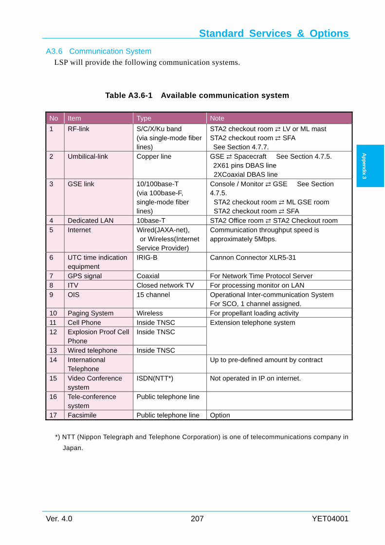
Standard Services & Options
Ver. 4.0 207 YET04001
Ap
pen
dix 3
Communication System A3.6
LSP will provide the following communication systems.
Table A3.6-1 Available communication system
No Item Type Note
1 RF-link S/C/X/Ku band (via single-mode fiber lines)
STA2 checkout room LV or ML mast STA2 checkout room SFA See Section 4.7.7.
2 Umbilical-link Copper line GSE Spacecraft See Section 4.7.5. 2X61 pins DBAS line 2XCoaxial DBAS line
3 GSE link
10/100base-T (via 100base-F, single-mode fiber lines)
Console / Monitor GSE See Section 4.7.5. STA2 checkout room ML GSE room STA2 checkout room SFA
4 Dedicated LAN 10base-T STA2 Office room STA2 Checkout room 5 Internet Wired(JAXA-net),
or Wireless(Internet Service Provider)
Communication throughput speed is approximately 5Mbps.
6 UTC time indication equipment
IRIG-B Cannon Connector XLR5-31
7 GPS signal Coaxial For Network Time Protocol Server 8 ITV Closed network TV For processing monitor on LAN 9 OIS 15 channel Operational Inter-communication System
For SCO, 1 channel assigned. 10 Paging System Wireless For propellant loading activity 11 Cell Phone Inside TNSC Extension telephone system 12 Explosion Proof Cell
Phone Inside TNSC
13 Wired telephone Inside TNSC 14 International
Telephone Up to pre-defined amount by contract
15 Video Conference system
ISDN(NTT*) Not operated in IP on internet.
16 Tele-conference system
Public telephone line
17 Facsimile Public telephone line Option
*) NTT (Nippon Telegraph and Telephone Corporation) is one of telecommunications company in
Japan.
Appendix 3
YET04001 208 Ver. 4.0
Ap
pen
dix 3
Options A3.7
Optional Services List A3.7.1
Table 3.7-1 shows overview of optional services.
Major Optional Activities A3.7.2
Spacecraft Propellant Loading (for chemical propulsion system) A3.7.2.1
(1) Procure propellant
(2) Prepare propellant loading equipment
(3) Fill spacecraft tank with propellant
(4) Pressurize flight tank
(5) Prepare contingency off-loading equipment
(6) Support propulsion system checkout
Separation Shock Test A3.7.2.2
SCO is required to verify that the spacecraft withstands the shock generated by the
separation.
As support of the shock test, LSP will ;
(1) Prepare payload adapter with separation system and ship to/from SCO test site.
(2) Final mate of the spacecraft to the payload adapter
(3) Install separation system
(4) Initiate separation.
(5) Review the test report generated by SCO.
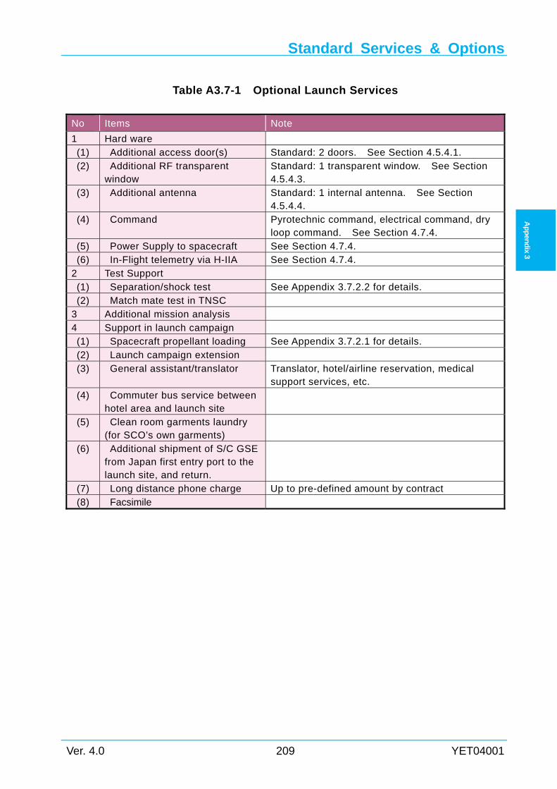
Standard Services & Options
Ver. 4.0 209 YET04001
Ap
pen
dix 3
Table A3.7-1 Optional Launch Services
No Items Note
1 Hard ware (1) Additional access door(s) Standard: 2 doors. See Section 4.5.4.1. (2) Additional RF transparent
window Standard: 1 transparent window. See Section 4.5.4.3.
(3) Additional antenna Standard: 1 internal antenna. See Section 4.5.4.4.
(4) Command Pyrotechnic command, electrical command, dry loop command. See Section 4.7.4.
(5) Power Supply to spacecraft See Section 4.7.4. (6) In-Flight telemetry via H-IIA See Section 4.7.4. 2 Test Support (1) Separation/shock test See Appendix 3.7.2.2 for details. (2) Match mate test in TNSC 3 Additional mission analysis 4 Support in launch campaign (1) Spacecraft propellant loading See Appendix 3.7.2.1 for details. (2) Launch campaign extension (3) General assistant/translator Translator, hotel/airline reservation, medical
support services, etc. (4) Commuter bus service between
hotel area and launch site
(5) Clean room garments laundry (for SCO’s own garments)
(6) Additional shipment of S/C GSE from Japan first entry port to the launch site, and return.
(7) Long distance phone charge Up to pre-defined amount by contract (8) Facsimile
Appendix 3
YET04001 210 Ver. 4.0
Ap
pen
dix 3
Intentionally blank
Appendix 4
Ver. 4.0 211 YET04001
Ap
pen
dix
4
Appendix 4 PAYLOAD ADAPTERS AND PAYLOAD
FAIRINGS
Several types of payload adapter are available as follows.
(1) Model 1194M shown in Appendix 4.1 (2) Model 1666MA shown in Appendix 4.2
Except 3 points shown below, low shock payload adapter Model 1194LS-H interface condition is same as Model 1194M, and low shock payload adapter Model 1666LS-H interface condition is same as Model 1666MA. Contact LSP for details.
i) Separation shock environment* ii) Clamp bands maximum tension iii) Stay-out zone around the PLA iv) Separation system keyway position
*) See Section 3.2, Figure 3.2-4 for separation shock environment of low shock payload adapter.
The information regarding H-IIA payload fairings are shown in Appendix 4.3.

Appendix 4
YET04001 212 Ver. 4.0
Ap
pen
dix 4
Intentionally blank
Appendix 4.1
Ver. 4.0 213 YET04001
Ap
pen
dix
4.1
Appendix 4.1 1194M ADAPTER A4.1
The main characteristics are as follows.
(1) Interface diameter : 1,215 mm
(2) Height : 480 mm
(3) Material : Aluminum Semi-monocoque
(4) Attached system : Clamp bands
(5) Separation springs : 4 - 8 springs
(6) Clamp band Maximum tension : 36.8 kN (32.0kN for Model 1194LS-H)
(7) Maximum load per spring : 1,670 N
(8) Adapter mass : 100 kg
This adapter has two (2) vent holes of 45 mm ø (1590.4 mm2) assuming that the internal
volume of the spacecraft is less than 2 m3.
When interface connectors are installed on the separation plane, connectors are located
789.125 mm from the center of the vehicle axis.
Figure A4.1-1 shows the photograph of the 1194M adapter.
Figure A4.1-2 shows a general view of the 1194M adapter.
Figure A4.1-3 to Figure A4.1-5 show details of the 1194M adapter.
Figure A4.1-6 to Figure A4.1-7 show the stay-out zone around the 1194M adapter.
Figure A4.1-8 shows the usable volume below 1194M adapter spacecraft separation plane.
Figure A4.1-9 shows the limit load of the 1194M adapter.
Figure A4.1-10 shows the spacecraft separation shock spectrum of the 1194M adapter.
Figure A4.1-11 shows the limit load at separation plane of the 1194M adapter.
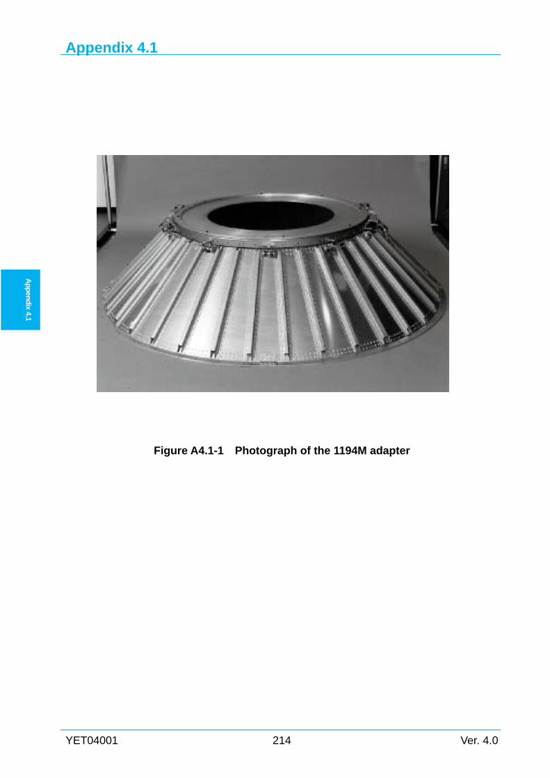
Appendix 4.1
YET04001 214 Ver. 4.0
Ap
pen
dix 4.1
Figure A4.1-1 Photograph of the 1194M adapter
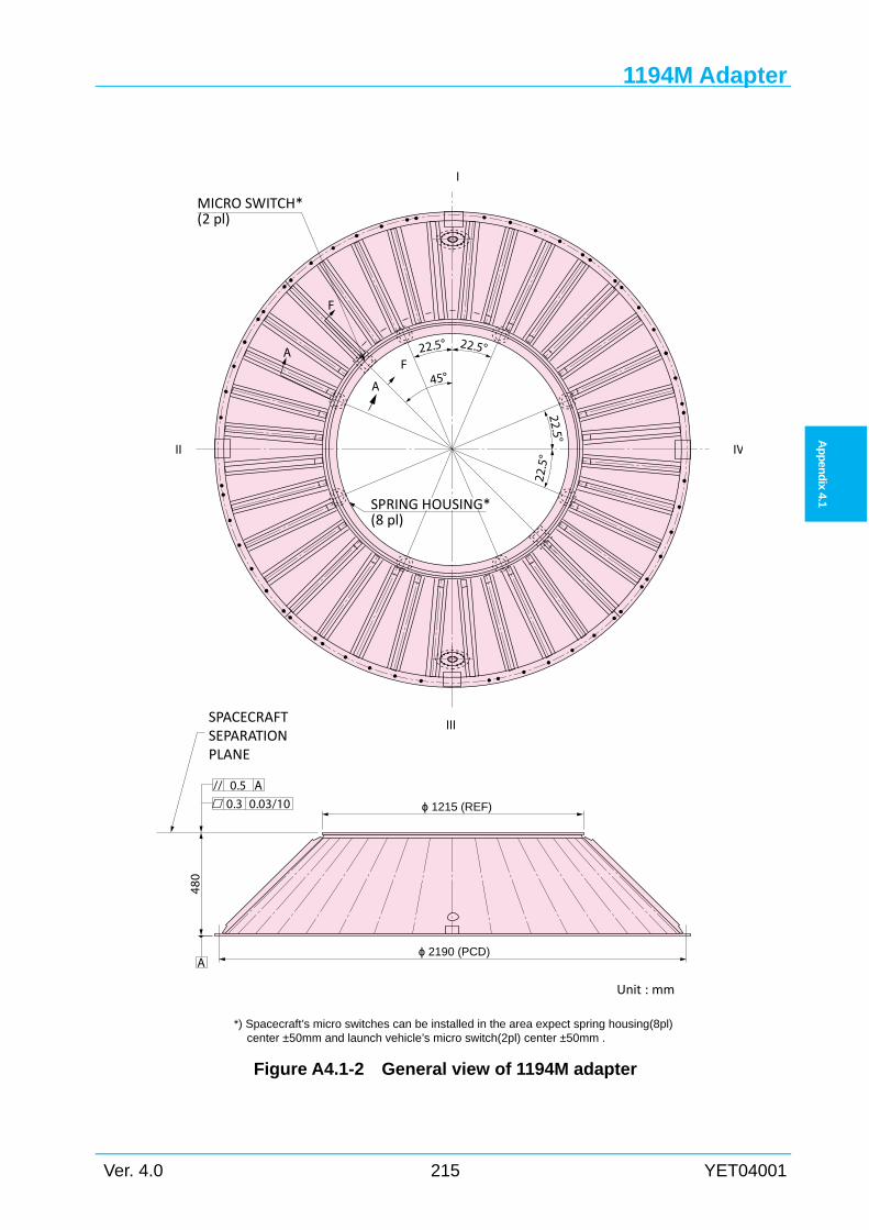
1194M Adapter
Ver. 4.0 215 YET04001
Ap
pen
dix
4.1
Figure A4.1-2 General view of 1194M adapter
MICRO SWITCH*(2 pl)
22.5°22.5°
45°
22.5
°
22.5°
I
IV
III
II
F
AF
A
SPRING HOUSING*(8 pl)
ϕ 1215 (REF)
A
// A0.50.3 0.03/10
SPACECRAFTSEPARATIONPLANE
480
ϕ 2190 (PCD)
Unit : mm
*) Spacecraft’s micro switches can be installed in the area expect spring housing(8pl) center ±50mm and launch vehicle’s micro switch(2pl) center ±50mm .
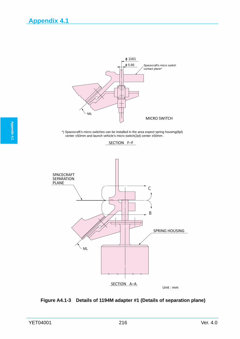
Appendix 4.1
YET04001 216 Ver. 4.0
Ap
pen
dix 4.1
Figure A4.1-3 Details of 1194M adapter #1 (Details of separation plane)
ϕ 1161
ML
SECTION F–F
C
B
SPRING HOUSING
ML
SPACECRAFTSEPARATIONPLANE
SECTION A–A
MICRO SWITCH
Unit : mm
Spacecraft’s micro switchcontact plane*
ϕ 5.66
*) Spacecraft’s micro switches can be installed in the area expect spring housing(8pl) center ±50mm and launch vehicle’s micro switch(2pl) center ±50mm .
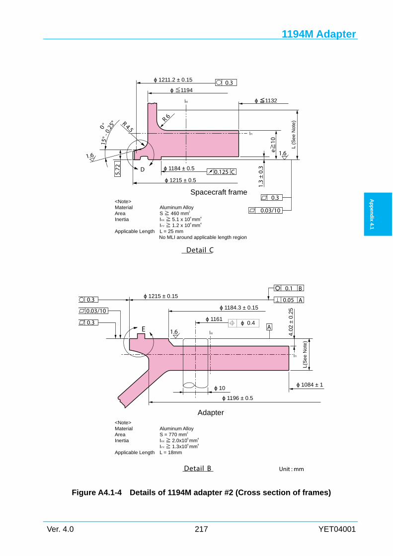
1194M Adapter
Ver. 4.0 217 YET04001
Ap
pen
dix
4.1
Figure A4.1-4 Details of 1194M adapter #2 (Cross section of frames)
ϕ 0.4
ϕ 1184 ± 0.5
ϕ 1215 ± 0.5
0.3
0.03/10
L (S
ee
Not
e)
1.3
± 0.
3
1.61.6
0.3
<Note>Material Aluminum AlloyArea S≧ 460 mm2
Inertia IXX≧ 5.1 x 104 mm4
IYY≧ 1.2 x 104 mm4
Applicable Length L = 25 mmNo MLI around applicable length region
Spacecraft frame
ϕ 1211.2 ± 0.15
R 4.5
R 6
5.72
e≧10
0.125 C
ϕ ≦1132
D
Detail C
IXX
IYY
ϕ≦1194
0.03/10
0.3
0.3 0.05
0.1
A
B
A
ϕ 1215 ± 0.15
ϕ 1184.3 ± 0.15
ϕ 1161
1.6
L(S
ee
No
te)
ϕ 1196 ± 0.5
<Note>Material Aluminum AlloyArea S = 770 mm2
Inertia IXX≧ 2.0x105 mm4
IYY≧ 1.3x104 mm4
Applicable Length L = 18mm
Adapter
Detail B
IXX
IYY
E
Unit : mm
4.02
± 0
.25
ϕ 1084 ± 1ϕ 10
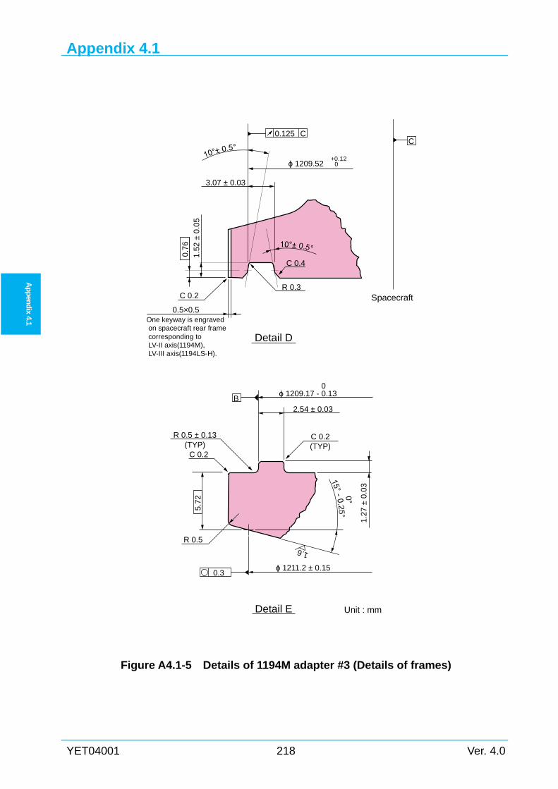
Appendix 4.1
YET04001 218 Ver. 4.0
Ap
pen
dix 4.1
Figure A4.1-5 Details of 1194M adapter #3 (Details of frames)
0.125 C
ϕ 1209.52 0
3.07 ± 0.03
+0.12
0.7
6
Detail D
0.5×0.5One keyway is engraved on spacecraft rear frame corresponding toLV-II axis(1194M),LV-III axis(1194LS-H).
C 0.2
C 0.4
R 0.3
C
Spacecraft
5.7
2
0.3
Bϕ 1209.17 - 0.13
0
2.54 ± 0.03
1.2
7 ±
0.0
3
1.6
ϕ 1211.2 ± 0.15
R 0.5 ± 0.13(TYP)
C 0.2
R 0.5
Detail E
C 0.2(TYP)
0°
Unit : mm
1.52
± 0
.05
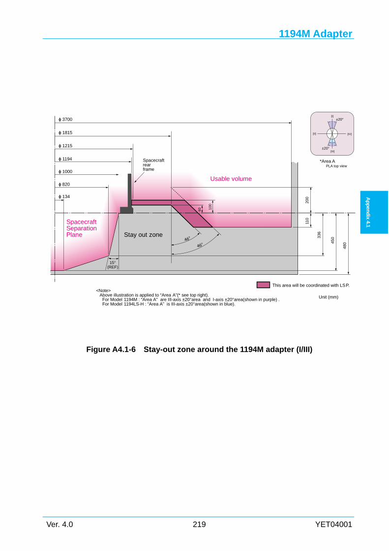
1194M Adapter
Ver. 4.0 219 YET04001
Ap
pen
dix
4.1
Figure A4.1-6 Stay-out zone around the 1194M adapter (I/III)
ϕ 1000
ϕ 1194
ϕ 1215
ϕ 1815
ϕ 3700
15°(REF)
Usable volume
[I]
[II]
[III]
[IV]
Spacecraftrearframe
Stay out zone
SpacecraftSeparationPlane
110
ϕ 820
ϕ 134
100
336
This area will be coordinated with LSP.
200
60
46°46°
±20°
±20°
450
480
Unit (mm)
*Area APLA top view
<Note>Above illustration is applied to “Area A”(* see top right).
For Model 1194M : “Area A” are III-axis ±20°area and I-axis ±20°area(shown in purple) . For Model 1194LS-H : “Area A” is III-axis ±20°area(shown in blue).
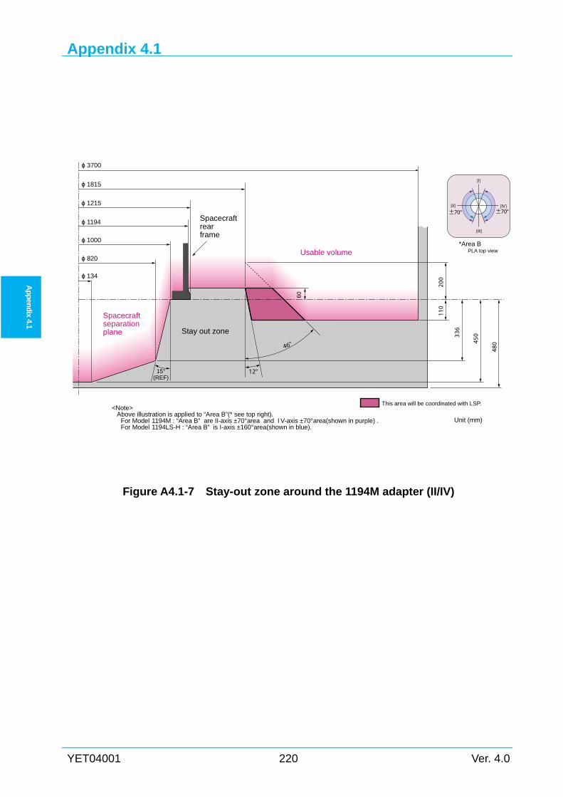
Appendix 4.1
YET04001 220 Ver. 4.0
Ap
pen
dix 4.1
Figure A4.1-7 Stay-out zone around the 1194M adapter (II/IV)
ϕ 1000
ϕ 1194
ϕ 1815
ϕ 3700
15°(REF)
Usable volume
Stay out zone
Spacecraftseparationplane
110
ϕ 820
ϕ 134
60
336
This area will be coordinated with LSP.
200
12°
ϕ 1215
Spacecraftrearframe
450
480
[I]
[II]
[III]
[IV]±70° ±70°
Unit (mm)
46°
<Note>Above illustration is applied to “Area B”(* see top right).
For Model 1194M : “Area B” are II-axis ±70°area and I V-axis ±70°area(shown in purple) . For Model 1194LS-H : “Area B” is I-axis ±160°area(shown in blue).
*Area BPLA top view
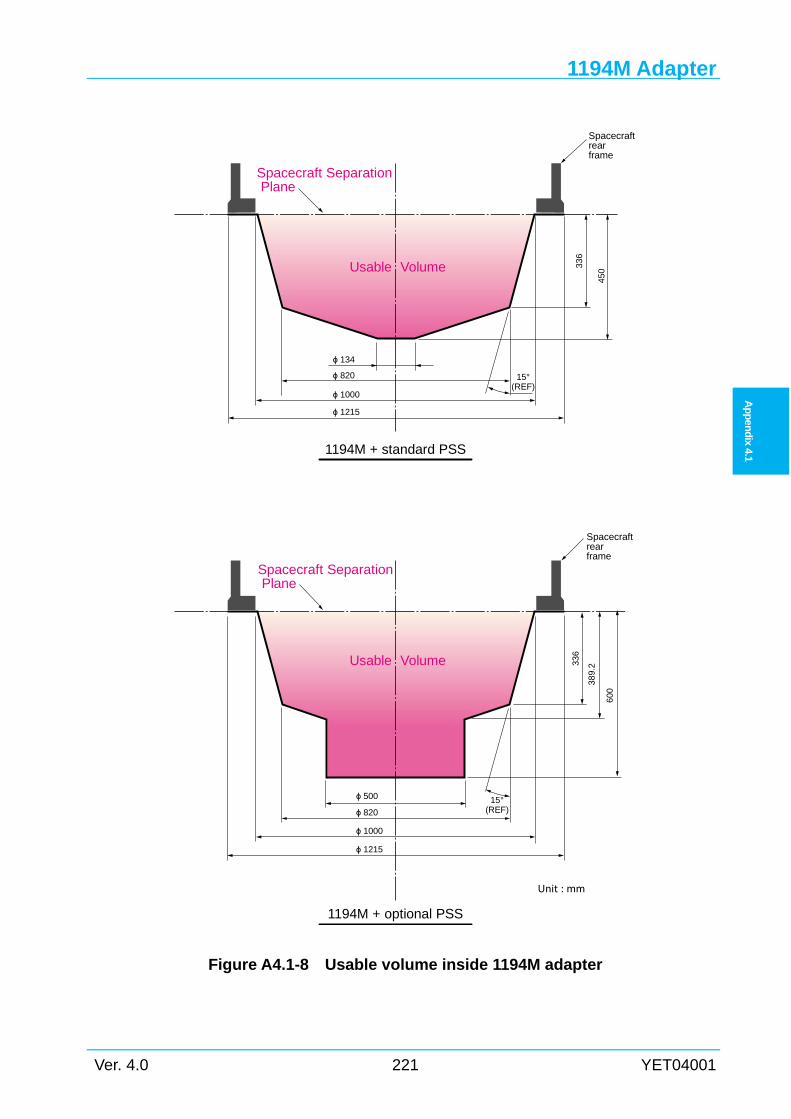
1194M Adapter
Ver. 4.0 221 YET04001
Ap
pen
dix
4.1
Figure A4.1-8 Usable volume inside 1194M adapter
ϕ 820
ϕ 1215
15°(REF)
Usable Volume
Spacecraftrearframe
600
ϕ 500
ϕ 134
336
ϕ 1000
ϕ 1215
389.
2
ϕ 820
ϕ 1000
450
336
Usable Volume
Spacecraft Separation Plane
15°(REF)
Spacecraftrearframe
1194M + standard PSS
1194M + optional PSS
Spacecraft Separation Plane
Unit : mm
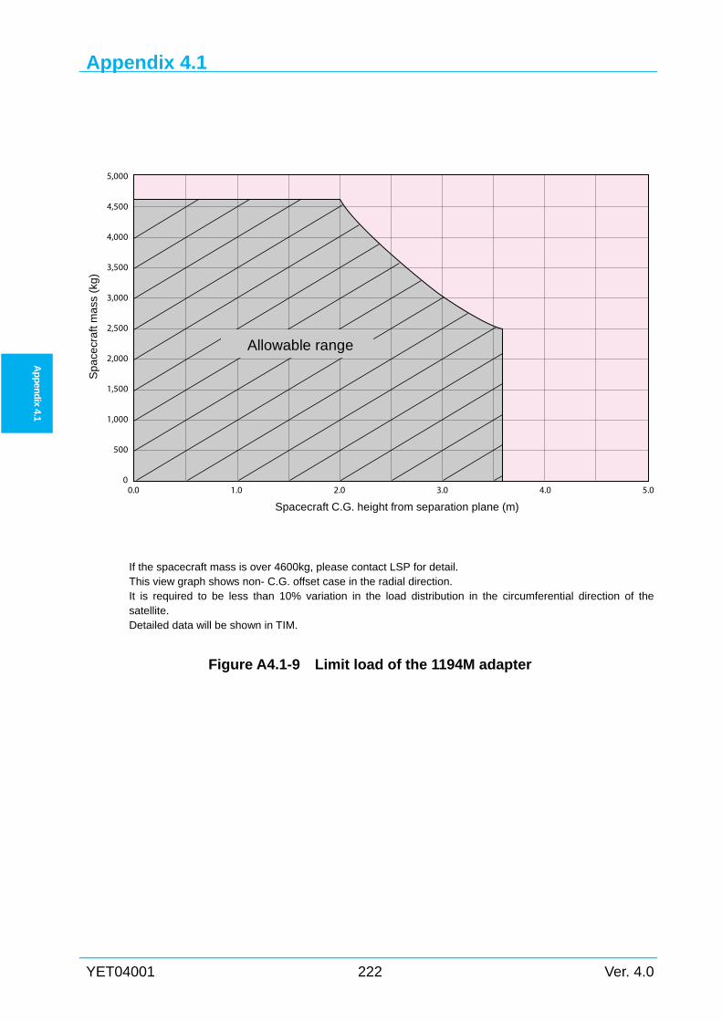
Appendix 4.1
YET04001 222 Ver. 4.0
Ap
pen
dix 4.1
If the spacecraft mass is over 4600kg, please contact LSP for detail. This view graph shows non- C.G. offset case in the radial direction. It is required to be less than 10% variation in the load distribution in the circumferential direction of the satellite. Detailed data will be shown in TIM.
Figure A4.1-9 Limit load of the 1194M adapter
0.0
5,000
4,500
4,000
3,500
3,000
2,500
2,000
1,500
1,000
500
01.0 2.0 3.0 4.0 5.0
Spacecraft C.G. height from separation plane (m)
Sp
ace
cra
ft m
ass
(kg
)
Allowable range
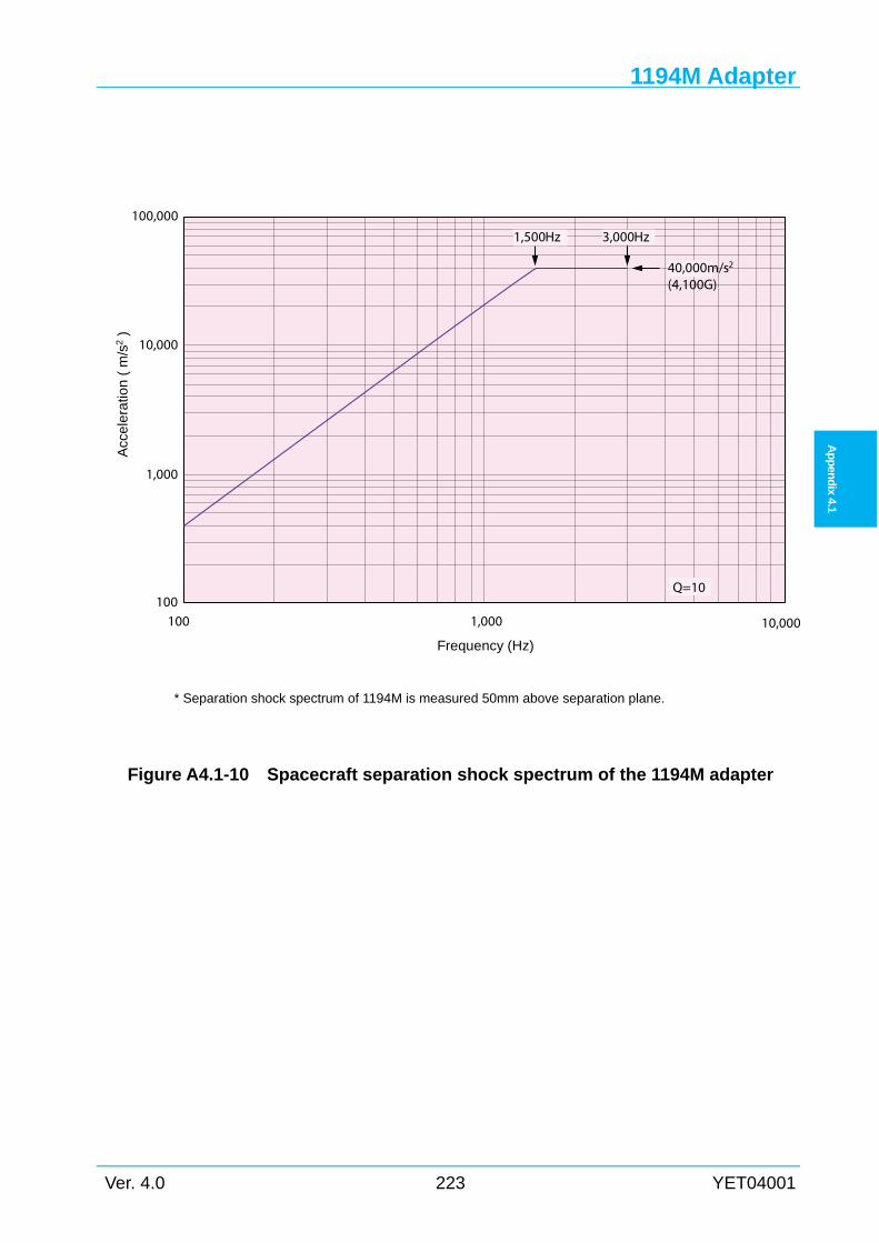
1194M Adapter
Ver. 4.0 223 YET04001
Ap
pen
dix
4.1
* Separation shock spectrum of 1194M is measured 50mm above separation plane.
Figure A4.1-10 Spacecraft separation shock spectrum of the 1194M adapter
100
1,000
10,000
100,000
100
Acc
ele
ratio
n (
m/s
2 )
1,000 10,000
Frequency (Hz)
40,000m/s2
(4,100G)
1,500Hz 3,000Hz
Q=10
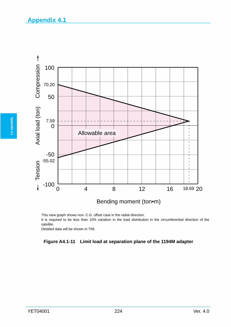
Appendix 4.1
YET04001 224 Ver. 4.0
Ap
pen
dix 4.1
This view graph shows non- C.G. offset case in the radial direction. It is required to be less than 10% variation in the load distribution in the circumferential direction of the satellite. Detailed data will be shown in TIM.
Figure A4.1-11 Limit load at separation plane of the 1194M adapter
0 4 8 12 16 20-100
-50
0
50
100
Allowable area
Bending moment (ton•m)
Axi
al lo
ad (
ton)
Tens
ion
Com
pres
sion
18.69
7.59
-55.02
70.20
Appendix 4.2
Ver. 4.0 225 YET04001
Ap
pen
dix
4.2
Appendix 4.2 1666MA ADAPTER
A4.2
The main characteristics are as follows.
(1) Interface diameter : 1,666 mm
(2) Height : 480 mm
(3) Material : Aluminum Semi-monocoque
(4) Attached system : Clamp bands
(5) Separation springs : 4 - 8 springs
(6) Clamp bands
Maximum tension : 38.9 kN (32.0kN for Model 1666LS-H)
(7) Maximum load per spring : 1,670 N
(8) Adapter mass : 100 kg
This adapter has four (4) vent holes of 45 mm ø (1590.4 mm2) assuming that the internal
volume of the spacecraft is less than 1.5 m3.
When interface connectors are installed on the separation plane, connectors are located 942.5
mm from the center of the vehicle axis.
Figure A4.2-1 shows the photograph of the 1666MA adapter.
Figure A4.2-2 shows a general view of the 1666MA adapter.
Figure A4.2-3 to Figure A4.2-5 show details of the 1666MA adapter.
Figure A4.2-6 to Figure A4.2-7 show the stay-out zone around the 1666MA adapter.
Figure A4.2-8 shows the usable volume below 1666MA adapter spacecraft separation plane.
Figure A4.2-9 shows the limit load of the 1666MA adapter.
Figure A4.2-10 shows the spacecraft separation shock spectrum of the 1666MA adapter.
Figure A4.2-11 shows the limit load at separation plane of the 1666MA adapter.
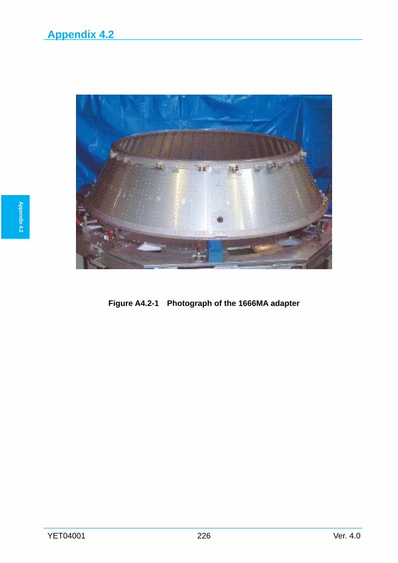
Appendix 4.2
YET04001 226 Ver. 4.0
Ap
pen
dix 4.2
Figure A4.2-1 Photograph of the 1666MA adapter
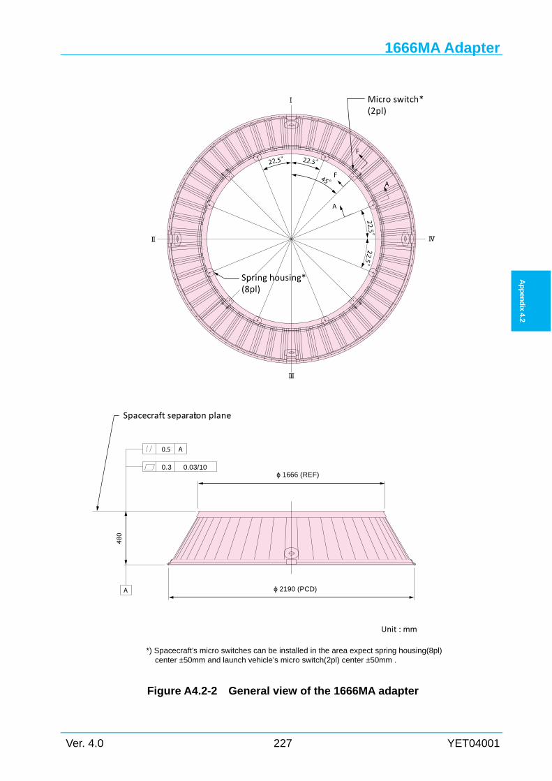
1666MA Adapter
Ver. 4.0 227 YET04001
Ap
pen
dix
4.2
Figure A4.2-2 General view of the 1666MA adapter
45°
Ⅰ
Ⅲ
ⅣⅡ
F
F
A
A
ϕ 1666 (REF)
ϕ 2190 (PCD)
0.5 A
0.3 0.03/10
A
Unit : mm
Spring housing*(8pl)
Spacecraft separation plane
Micro switch*(2pl)
*) Spacecraft’s micro switches can be installed in the area expect spring housing(8pl) center ±50mm and launch vehicle’s micro switch(2pl) center ±50mm .
480
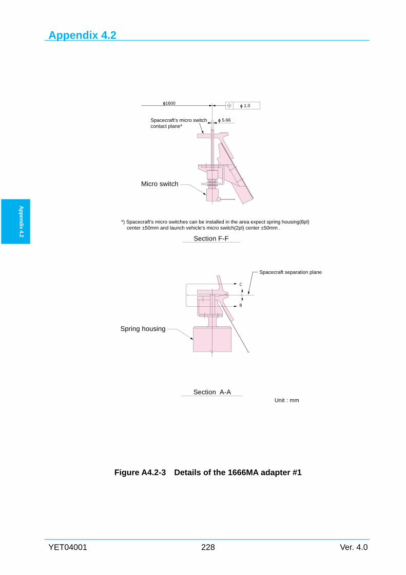
Appendix 4.2
YET04001 228 Ver. 4.0
Ap
pen
dix 4.2
Figure A4.2-3 Details of the 1666MA adapter #1
Section A-AUnit : mm
C
B
Section F-F
ϕ1600
Micro switch
Spacecraft separation plane
Spring housing
ϕ 5.66
*) Spacecraft’s micro switches can be installed in the area expect spring housing(8pl) center ±50mm and launch vehicle’s micro switch(2pl) center ±50mm .
ϕ 1.0
Spacecraft’s micro switchcontact plane*
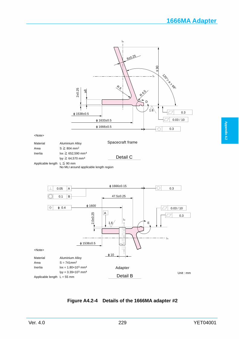
1666MA Adapter
Ver. 4.0 229 YET04001
Ap
pen
dix
4.2
Figure A4.2-4 Details of the 1666MA adapter #2
Detail B
A
Unit : mm
1.6
ϕ 1666±0.15
47.5±0.25
0.05 A
0.1 B
0.3
ϕ 1600
ϕ 1538±0.5
0.03 / 10
0.3
AdapterInertia
Applicable length
Area
<Note>
Material
lxx = 1.80×105 mm4
lyy = 3.39×105 mm4
L = 55 mm
S = 741mm2
Aluminium Alloy
E
≤ 9
0
R 4.5
R 6
120°> α > 69°
1.6
0.03 / 10
0.3
ϕ 1666±0.5
ϕ 1633±0.5
ϕ 1538±0.5
6±0.25
>8
2±
0.2
5
lyy ≧ 64,570 mm4
lxx ≧ 652,590 mm4
S≧ 804 mm2Area
Applicable length
Inertia
Material
<Note>
Aluminium Alloy
Detail C
Spacecraft frame
L≦ 90 mmNo MLI around applicable length region
D
2.0
±0
.25
ϕ 10
0.3
IYY
IXX
IYY
ϕ 0.4
IXX
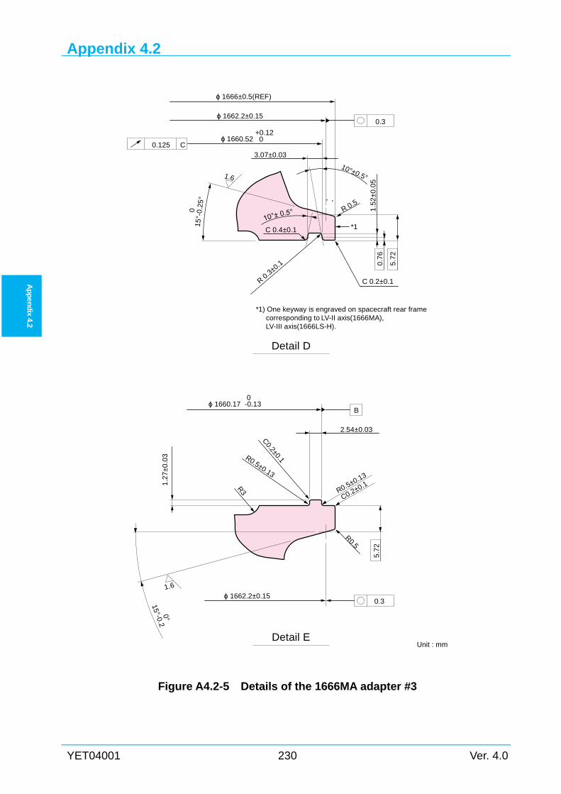
Appendix 4.2
YET04001 230 Ver. 4.0
Ap
pen
dix 4.2
Figure A4.2-5 Details of the 1666MA adapter #3
*1) One keyway is engraved on spacecraft rear frame corresponding to LV-II axis(1666MA),
LV-III axis(1666LS-H).
*1
3.07±0.03
10°±0.5°
R 0.5
0.125 C
0.3
1.6
Detail D
2.54±0.03
ϕ 1660.17 -0.130
C0.2±0.1R0.5±0.13
R0.5
ϕ 1662.2±0.150.3
C0.2±0.1R0.5±0.13
R3
1.6
Detail EUnit : mm
B
C 0.2±0.1
ϕ 1660.52 0+0.12
ϕ 1666±0.5(REF)
ϕ 1662.2±0.15
0.7
6
5.7
2
R 0.3±0.1
1.5
2±
0.0
5
C 0.4±0.1
1.2
7±
0.0
3
15°-0.20°
15°-
0.25
°0
5.7
2
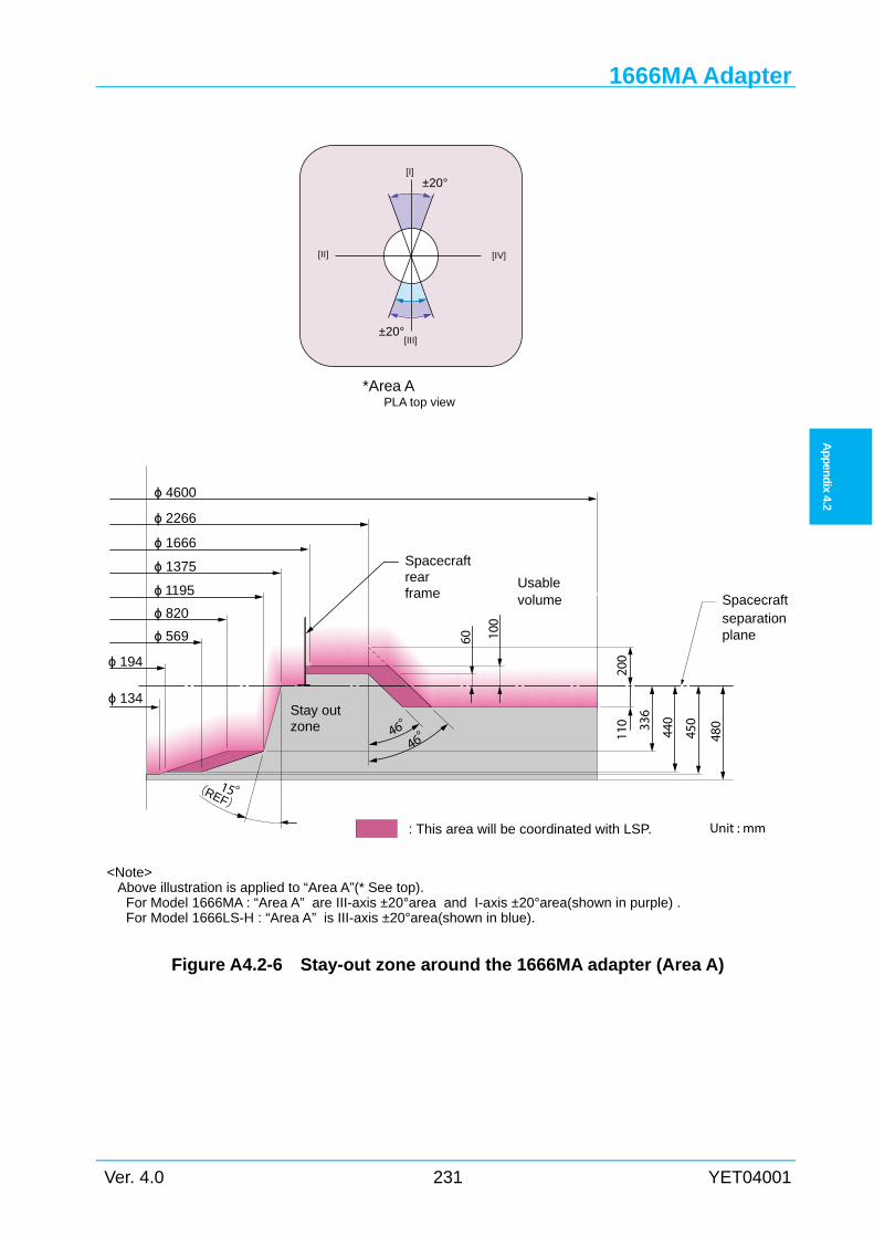
1666MA Adapter
Ver. 4.0 231 YET04001
Ap
pen
dix
4.2
Figure A4.2-6 Stay-out zone around the 1666MA adapter (Area A)
[I]
[II]
[III]
[IV]
±20°
±20°
*Area APLA top view
<Note>Above illustration is applied to “Area A”(* See top).
For Model 1666MA : “Area A” are III-axis ±20°area and I-axis ±20°area(shown in purple) . For Model 1666LS-H : “Area A” is III-axis ±20°area(shown in blue).
Unit : mm
ϕ 4600
ϕ 2266
ϕ 1666
ϕ 1375
ϕ 1195
ϕ 820
ϕ 569
ϕ 194
ϕ 134
46°
15°(REF)
Spacecraftseparationplane
volumeUsable
Stay outzone
Spacecraftrearframe
: This area will be coordinated with LSP.
46° 336
440
450
480
110
200
60 100
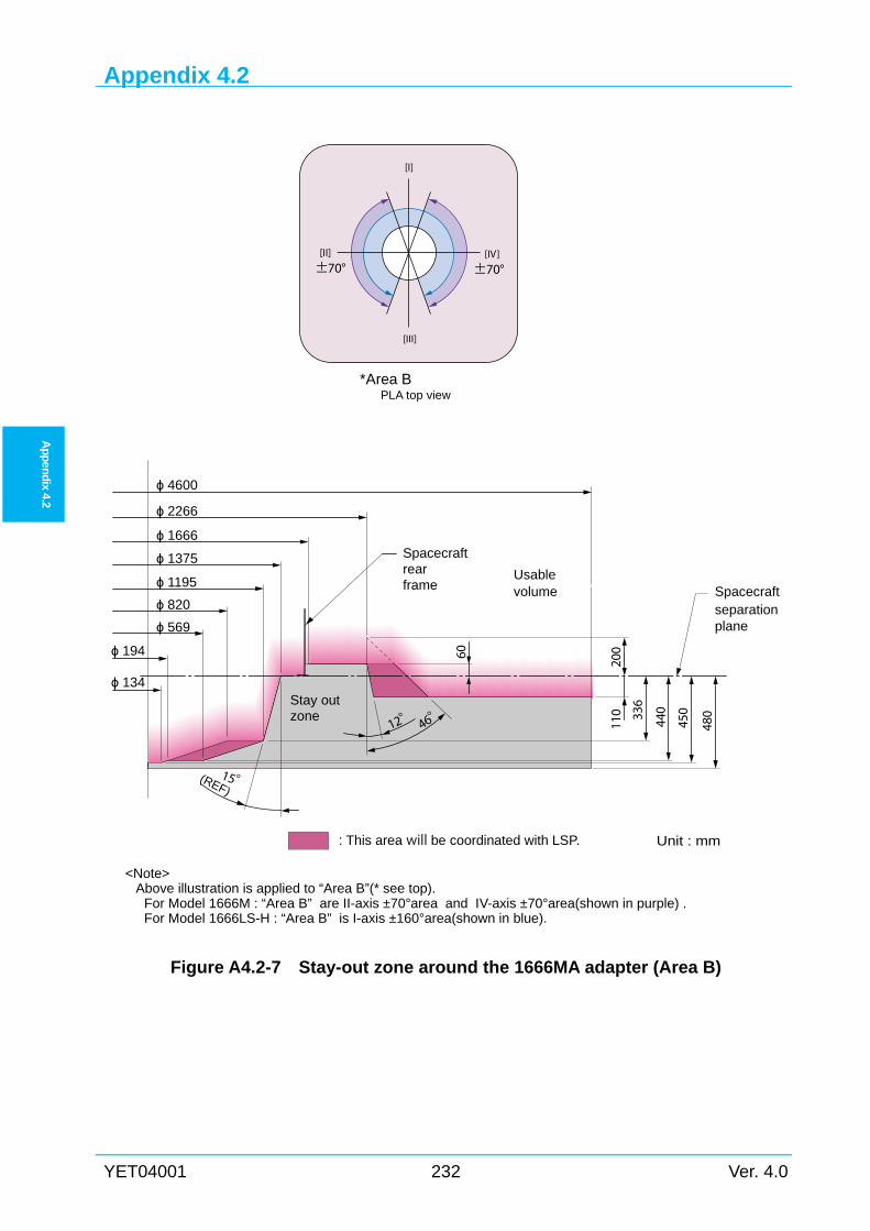
Appendix 4.2
YET04001 232 Ver. 4.0
Ap
pen
dix 4.2
Figure A4.2-7 Stay-out zone around the 1666MA adapter (Area B)
*Area BPLA top view
[I]
[II]
[III]
[IV]±70° ±70°
<Note>Above illustration is applied to “Area B”(* see top).
For Model 1666M : “Area B” are II-axis ±70°area and IV-axis ±70°area(shown in purple) . For Model 1666LS-H : “Area B” is I-axis ±160°area(shown in blue).
Unit : mm
ϕ 4600
ϕ 2266
ϕ 1666
ϕ 1375
ϕ 1195
ϕ 820
ϕ 569
ϕ 194
ϕ 134
12° 46°
15°(REF)
Spacecraftseparationplane
volumeUsable
Stay outzone
Spacecraftrearframe
: This area will be coordinated with LSP.
336
440
450
480
110
20060
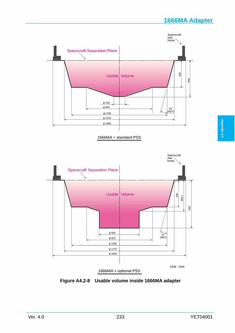
1666MA Adapter
Ver. 4.0 233 YET04001
Ap
pen
dix
4.2
Figure A4.2-8 Usable volume inside 1666MA adapter
1666MA + standard PSS
1666MA + optional PSS
ϕ 820
ϕ 1375
15°(REF)
Usable Volume
Spacecraftrearframe
600
ϕ 500
ϕ 134
336
ϕ 1195
ϕ 1375
389
.2
ϕ 820
ϕ 1195
45
0
Usable Volume
15°(REF)
ϕ 1666
ϕ 1666
336
Spacecraftrearframe
Unit : mm
Spacecraft Separation Plane
Spacecraft Separation Plane
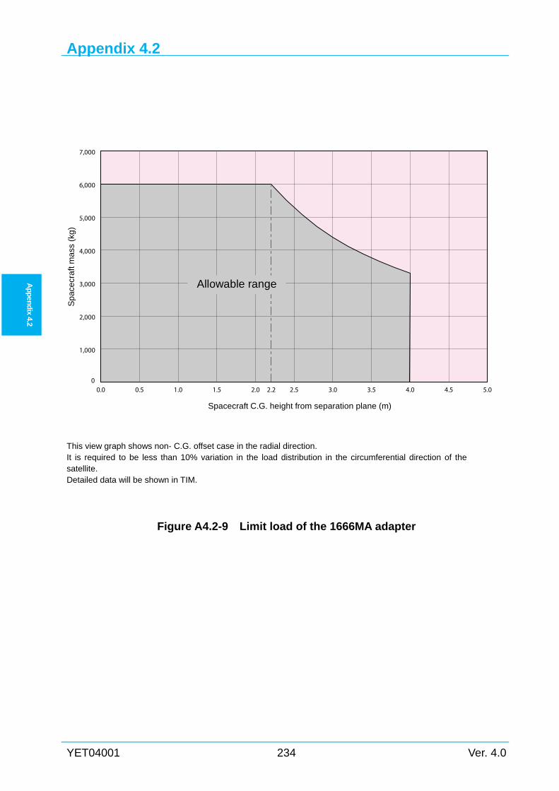
Appendix 4.2
YET04001 234 Ver. 4.0
Ap
pen
dix 4.2
This view graph shows non- C.G. offset case in the radial direction. It is required to be less than 10% variation in the load distribution in the circumferential direction of the satellite. Detailed data will be shown in TIM.
Figure A4.2-9 Limit load of the 1666MA adapter
0.0 0.5 1.0 1.5 2.0 2.2 2.5 3.0 3.5 4.0 4.5 5.00
1,000
2,000
3,000
4,000
5,000
6,000
7,000
Spacecraft C.G. height from separation plane (m)
Sp
acec
raft
ma
ss (
kg)
Allowable range
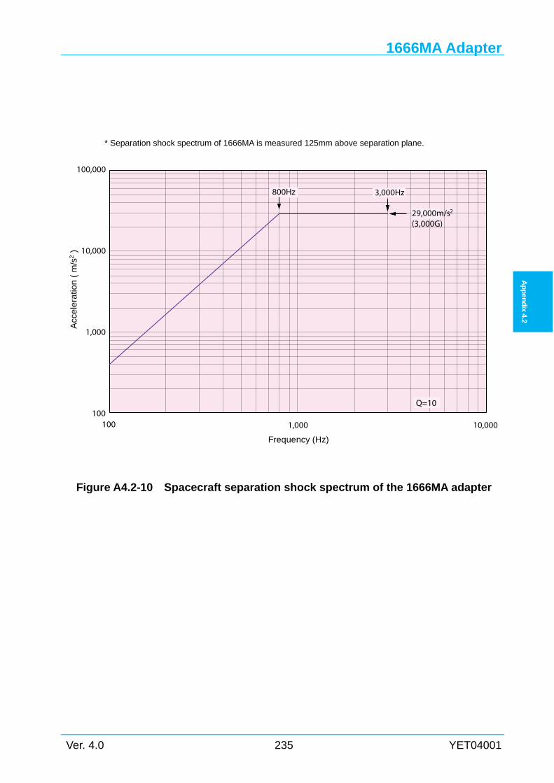
1666MA Adapter
Ver. 4.0 235 YET04001
Ap
pen
dix
4.2
* Separation shock spectrum of 1666MA is measured 125mm above separation plane.
Figure A4.2-10 Spacecraft separation shock spectrum of the 1666MA adapter
100
1,000
10,000
100,000
100
Acc
ele
ratio
n (
m/s
2 )
1,000 10,000
Frequency (Hz)
29,000m/s2
(3,000G)
800Hz 3,000Hz
Q=10
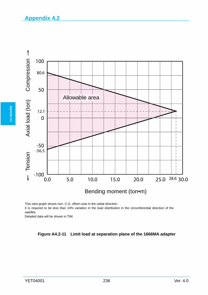
Appendix 4.2
YET04001 236 Ver. 4.0
Ap
pen
dix 4.2
This view graph shows non- C.G. offset case in the radial direction. It is required to be less than 10% variation in the load distribution in the circumferential direction of the satellite. Detailed data will be shown in TIM.
Figure A4.2-11 Limit load at separation plane of the 1666MA adapter
0.0 5.0 10.0 15.0 20.0 25.0 30.0-100
-50
0
50
100
Allowable area
Bending moment (ton•m)
28.6
12.1
-56.5
80.6
Axi
al lo
ad (
ton)
Tens
ion
Com
pres
sion
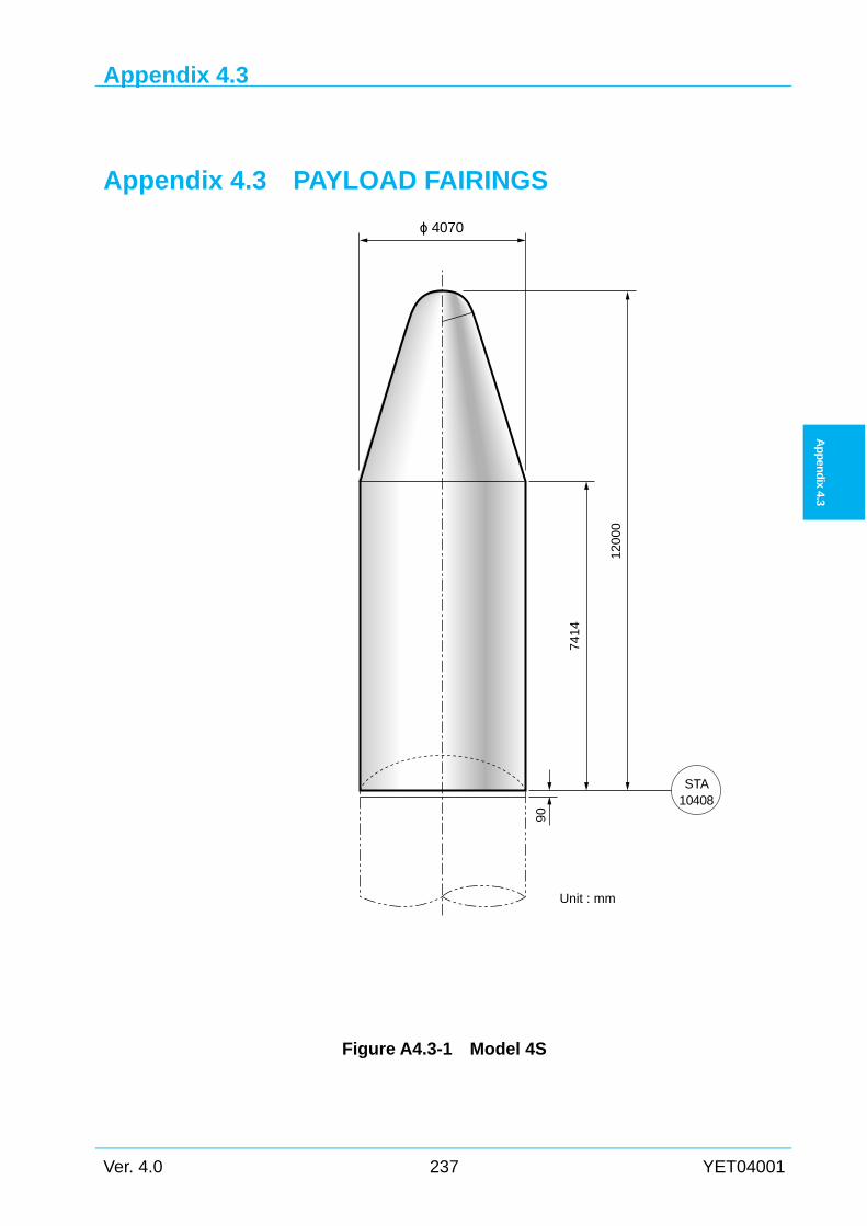
Appendix 4.3
Ver. 4.0 237 YET04001
Ap
pen
dix
4.3
Appendix 4.3 PAYLOAD FAIRINGS
A4.3
Figure A4.3-1 Model 4S
ϕ 4070
STA10408
Unit : mm
90
7414
1200
0
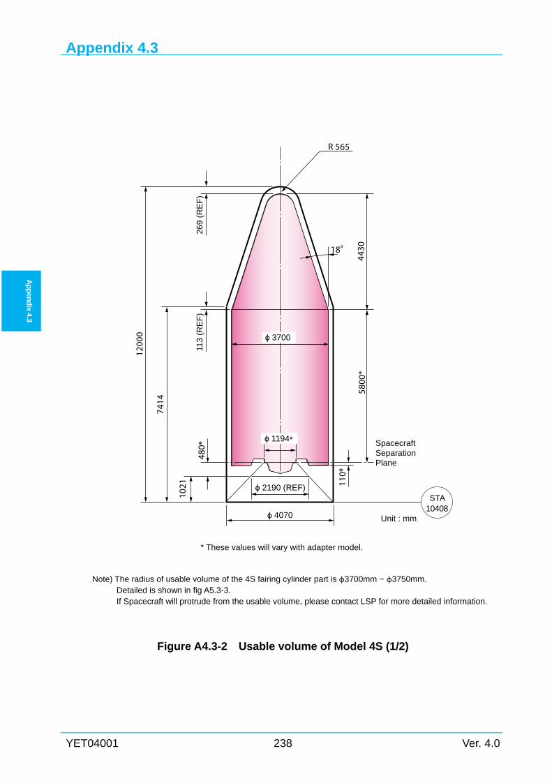
Appendix 4.3
YET04001 238 Ver. 4.0
Ap
pen
dix 4.3
Note) The radius of usable volume of the 4S fairing cylinder part is φ3700mm ~ φ3750mm.
Detailed is shown in fig A5.3-3. If Spacecraft will protrude from the usable volume, please contact LSP for more detailed information.
Figure A4.3-2 Usable volume of Model 4S (1/2)
R 565
18°
ϕ 2190 (REF)
ϕ 4070
ϕ 1194*
ϕ 3700
1200
0
7414
480 *
113
(RE
F)
5800
*
SpacecraftSeparationPlane
Unit : mm
110 *
269
(RE
F)
4430
* These values will vary with adapter model.
1021
STA10408
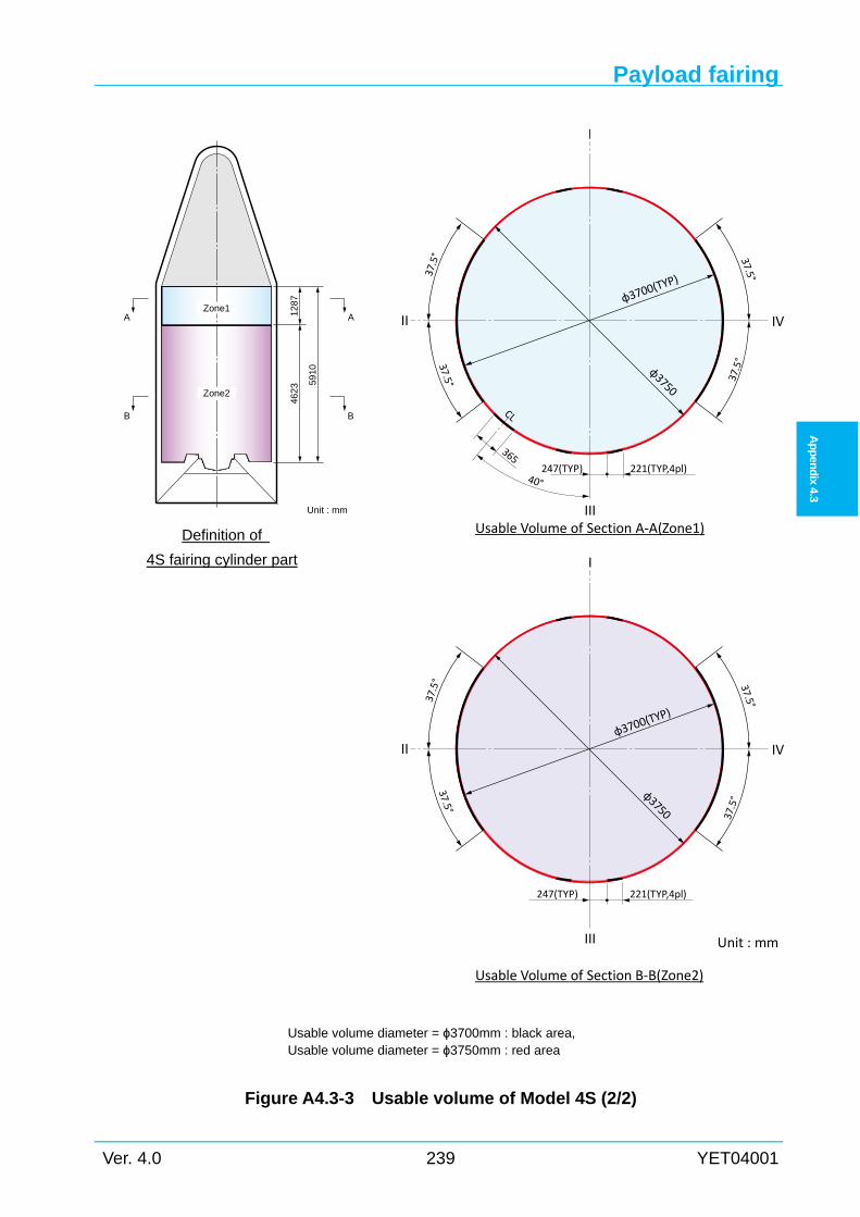
Payload fairing
Ver. 4.0 239 YET04001
Ap
pen
dix
4.3
Unit : mm
φ3700(T
YP)
φ3750
φ3700(T
YP)
φ3750
221(TYP,4pl)247(TYP)
221(TYP,4pl)247(TYP)
365
40°
CL37.5°
37.5°
37.5°
37.5°37.5°
37.5°37.5°
37.5°
I
II
III
IV
I
II
III
IV
Usable Volume of Section A‐A(Zone1)
Usable Volume of Section B‐B(Zone2)
Figure A4.3-3 Usable volume of Model 4S (2/2)
Unit : mm
5910
Zone1 1287
AA
Zone2
4623
BB
Definition of
4S fairing cylinder part
Usable volume diameter = ϕ3700mm : black area, Usable volume diameter = ϕ3750mm : red area
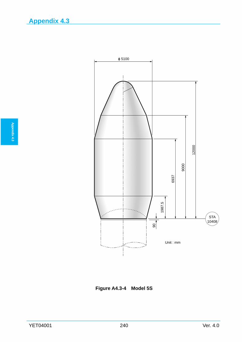
Appendix 4.3
YET04001 240 Ver. 4.0
Ap
pen
dix 4.3
Figure A4.3-4 Model 5S
STA10408
ϕ 5100
1200
0
9000
6937
1987
.5
Unit : mm
90
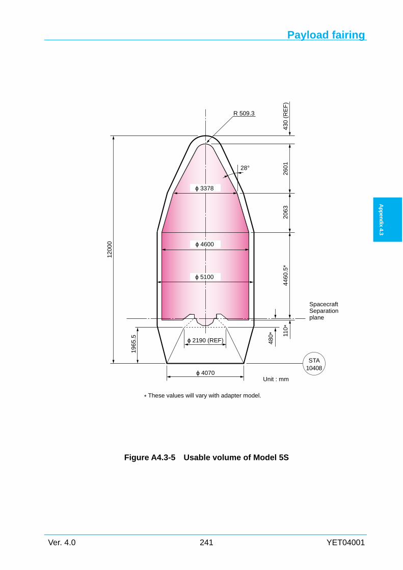
Payload fairing
Ver. 4.0 241 YET04001
Ap
pen
dix
4.3
Figure A4.3-5 Usable volume of Model 5S
R 509.3
ϕ 4070
ϕ 4600
120
00
196
5.5
SpacecraftSeparationplane
480 *
ϕ 2190 (REF)
28°
430
(R
EF
)26
01
206
344
60.5
*
Unit : mm
110
*
ϕ 3378
* These values will vary with adapter model.
ϕ 5100
STA10408
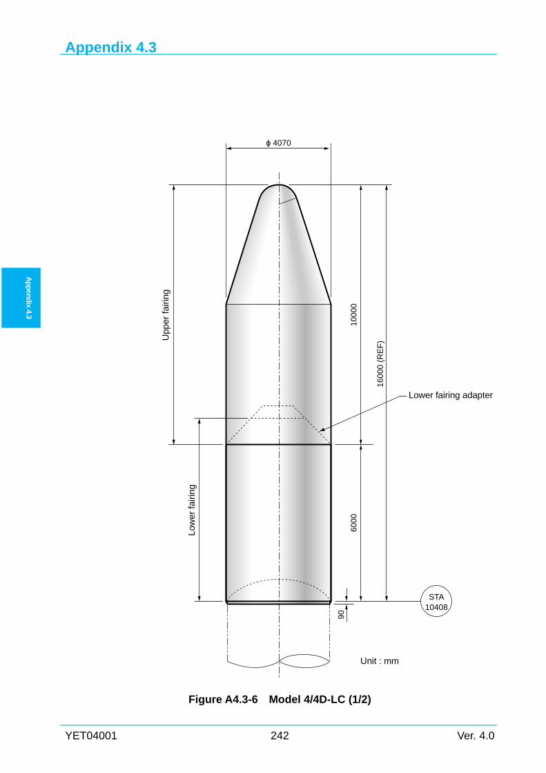
Appendix 4.3
YET04001 242 Ver. 4.0
Ap
pen
dix 4.3
Figure A4.3-6 Model 4/4D-LC (1/2)
ϕ 4070
100
00
1600
0 (R
EF
)
Lower fairing adapter
600
0
Low
er fa
iring
Upp
er fa
iring
90
Unit : mm
STA10408
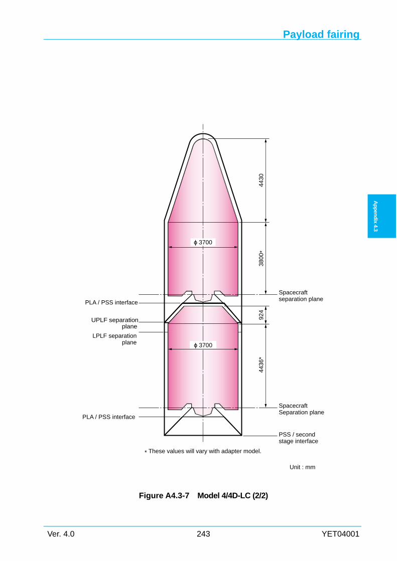
Payload fairing
Ver. 4.0 243 YET04001
Ap
pen
dix
4.3
Figure A4.3-7 Model 4/4D-LC (2/2)
Spacecraftseparation plane
PLA / PSS interface
UPLF separation plane
PLA / PSS interface
LPLF separationplane
PSS / secondstage interface
380
0*
443
04
436
*92
4
SpacecraftSeparation plane
Unit : mm
* These values will vary with adapter model.
ϕ 3700
ϕ 3700
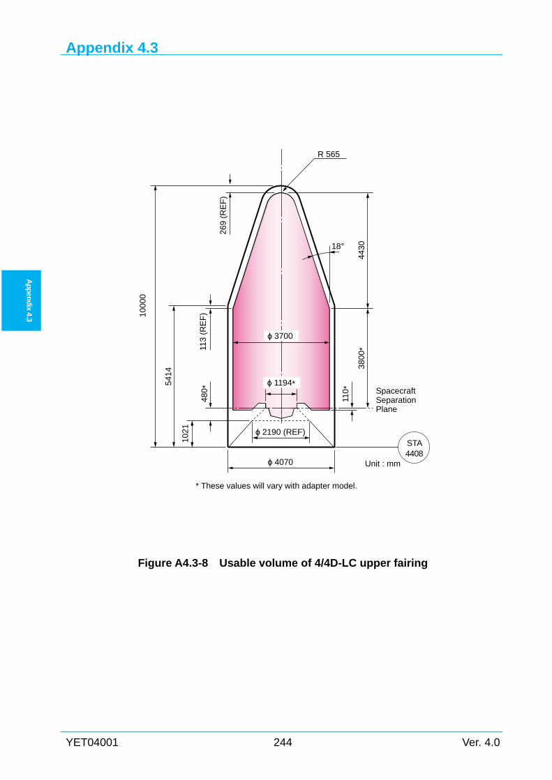
Appendix 4.3
YET04001 244 Ver. 4.0
Ap
pen
dix 4.3
Figure A4.3-8 Usable volume of 4/4D-LC upper fairing
R 565
18°
ϕ 4070
ϕ 1194*
ϕ 3700
1000
0
5414
1021
480 *
110 *
113
(RE
F)
3800
*
SpacecraftSeparationPlane
Unit : mm
269
(RE
F)
* These values will vary with adapter model.
4430
ϕ 2190 (REF)STA4408
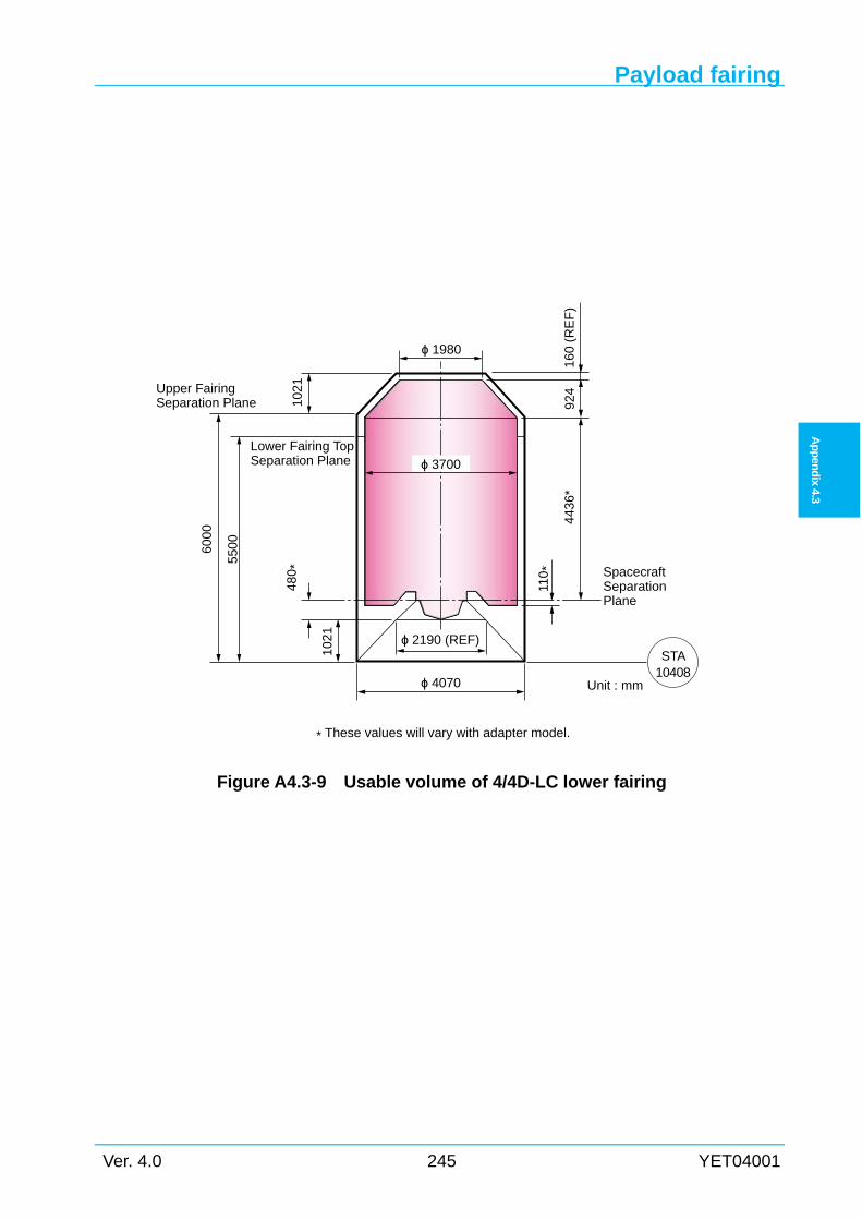
Payload fairing
Ver. 4.0 245 YET04001
Ap
pen
dix
4.3
Figure A4.3-9 Usable volume of 4/4D-LC lower fairing
1021
6000
480
*
443
6*
ϕ 4070
924
550
0
SpacecraftSeparationPlane
Unit : mm
* These values will vary with adapter model.
102
1
ϕ 3700
110
*
ϕ 2190 (REF)
Lower Fairing TopSeparation Plane
160
(RE
F)
ϕ 1980
STA10408
Upper FairingSeparation Plane
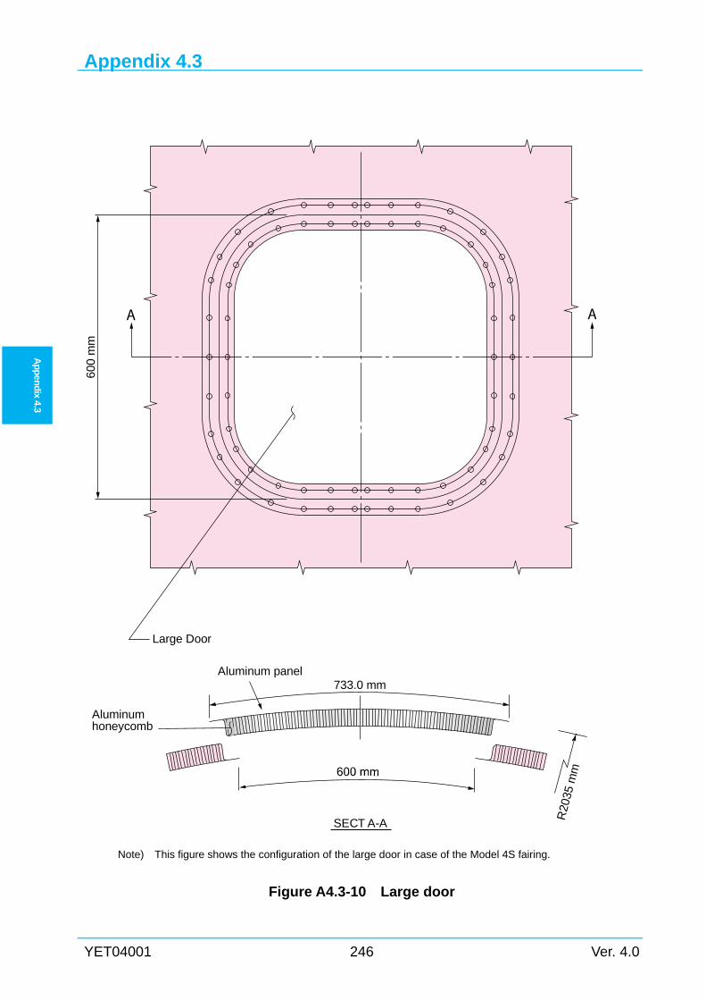
Appendix 4.3
YET04001 246 Ver. 4.0
Ap
pen
dix 4.3
Note) This figure shows the configuration of the large door in case of the Model 4S fairing.
Figure A4.3-10 Large door
600
mm
Large Door
Aluminumhoneycomb
Aluminum panel733.0 mm
SECT A-A R20
35 m
m
A A
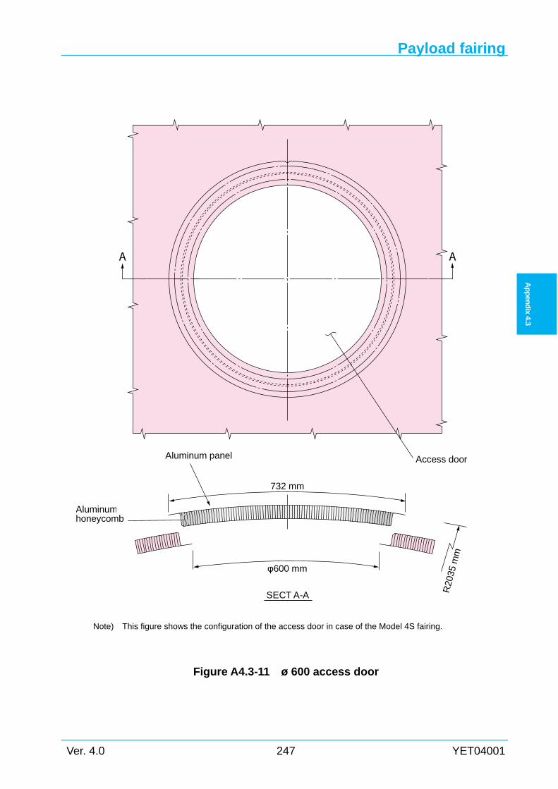
Payload fairing
Ver. 4.0 247 YET04001
Ap
pen
dix
4.3
Note) This figure shows the configuration of the access door in case of the Model 4S fairing.
Figure A4.3-11 ø 600 access door
A A
Access door
Aluminumhoneycomb
Aluminum panel
SECT A-A R20
35 m
m
732 mm
φ600 mm
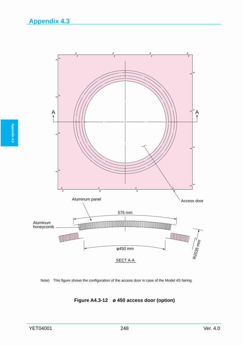
Appendix 4.3
YET04001 248 Ver. 4.0
Ap
pen
dix 4.3
A A
Access door
Aluminumhoneycomb
Aluminum panel
SECT A-A R20
35 m
m
576 mm
φ450 mm
Note) This figure shows the configuration of the access door in case of the Model 4S fairing.
Figure A4.3-12 ø 450 access door (option)
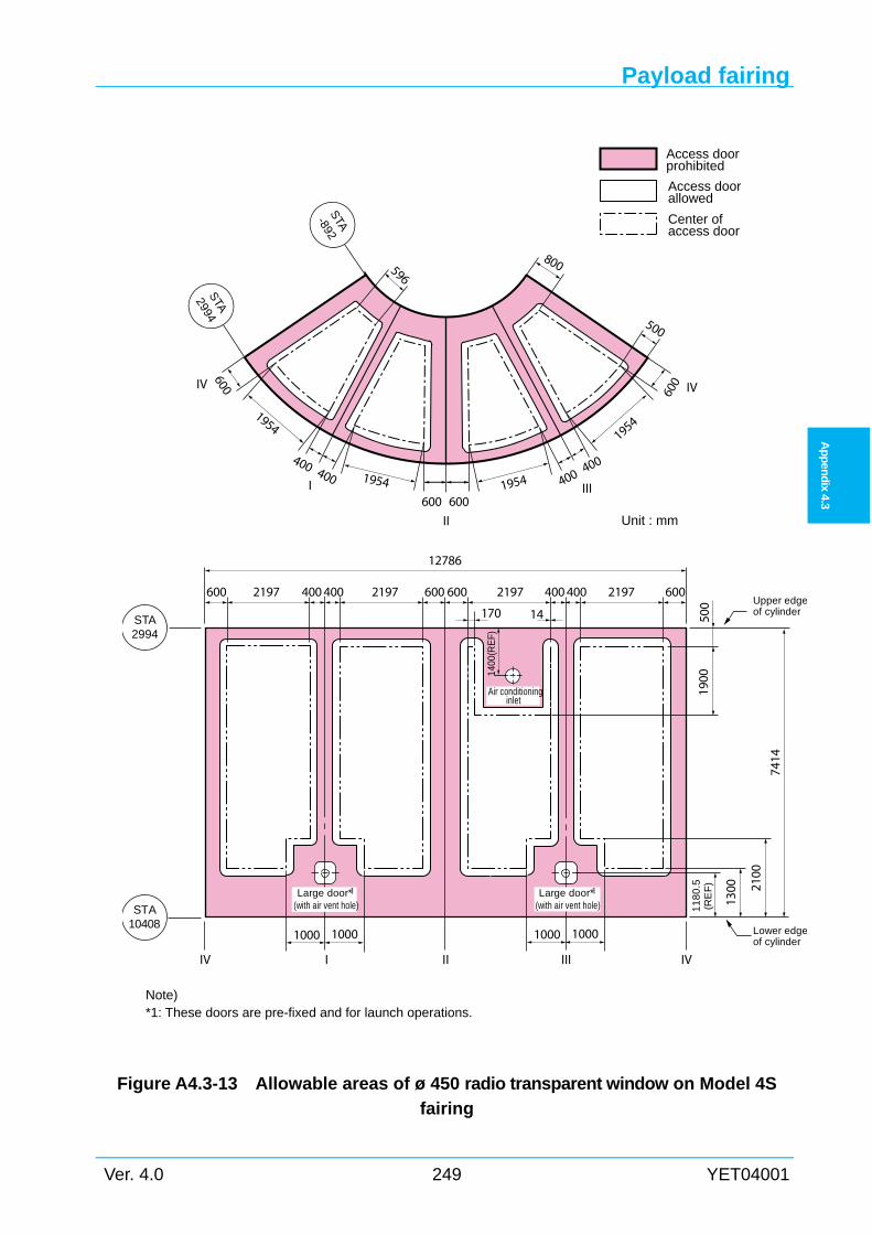
Payload fairing
Ver. 4.0 249 YET04001
Ap
pen
dix
4.3
Note) *1: These doors are pre-fixed and for launch operations.
Figure A4.3-13 Allowable areas of ø 450 radio transparent window on Model 4S
fairing
Unit : mm
Access doorprohibited
Access doorallowed
Center ofaccess door
II
I600 600
400 400
1954
400 400
1954
III19541954
600
STA2994
STA-892
500
800
IV IV
600
STA2994
600 400 600 600 400 6002197
12786
14 500
1900
2100
7414
219721972197 400
IVIIV II III
400
10001000
1300
10001000
11
80
.5(R
EF
)
Large door* (with air vent hole)
1 Large door* (with air vent hole)
1
170
STA10408
1400
(RE
F)
Air conditioninginlet
Lower edgeof cylinder
Upper edgeof cylinder
596
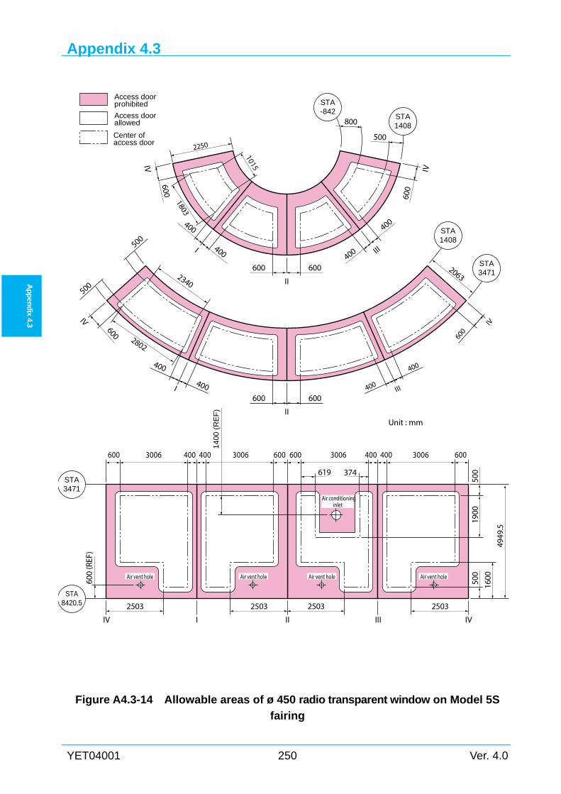
Appendix 4.3
YET04001 250 Ver. 4.0
Ap
pen
dix 4.3
Figure A4.3-14 Allowable areas of ø 450 radio transparent window on Model 5S
fairing
4949
.5
400
400
III
400
400I
600 600
II
60060
0IV IV
STA-842
800
500
STA1408
Access doorprohibited
Access doorallowed
Center ofaccess door
2250
500
500
STA1408
STA3471
600 600
II
600 600
400
400I 400
400
III
IV IV
Unit : mm
2063
STA3471
II III IVIIV
619
2503 25032503 2503
500
500
1600
STA8420.5
1900
374
400400600 400400600600 6003006300630063006
Air vent hole
Air conditioninginlet
Air vent hole Air vent holeAir vent hole
2802
2340
600
(REF
)
14
00
(R
EF
)
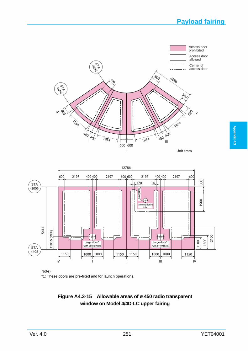
Payload fairing
Ver. 4.0 251 YET04001
Ap
pen
dix
4.3
Note) *1: These doors are pre-fixed and for launch operations.
Figure A4.3-15 Allowable areas of ø 450 radio transparent
window on Model 4/4D-LC upper fairing
Unit : mmII
I600 600
400 400
1954
400 400
1954
III19541954
600
500
800 4086
IV IV
600
5414
600 400 600 600 400 6002197
12786
500
1900
2100
219721972197 400
IVIIV II III
400
1000100011501150
1300
1150
1100
115010001000
1180
.5 (R
EF)
14170
Access doorprohibited
Access doorallowed
Center ofaccess door
Air conditioninginlet
Large door* (with air vent hole)
1 Large door* (with air vent hole)
1
STA4408
STA-1006
STA
-4892
STA
-1006
596
1400
(RE
F)
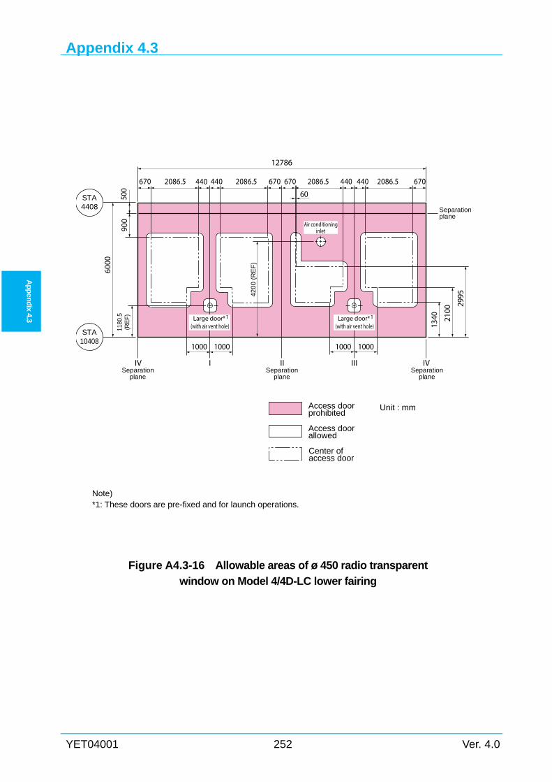
Appendix 4.3
YET04001 252 Ver. 4.0
Ap
pen
dix 4.3
Note) *1: These doors are pre-fixed and for launch operations.
Figure A4.3-16 Allowable areas of ø 450 radio transparent
window on Model 4/4D-LC lower fairing
STA4408
900
STA10408
6000
1340
Access doorprohibited
Access doorallowed
Unit : mm
Center ofaccess door
2100
1180
.5(R
EF)
2995
IVIIV II III
1000100010001000
670 440 670 670
12786
2086.52086.52086.5 440 440 6702086.5440
500 60
Large door* (with air vent hole)
1
Air conditioninginlet
Large door* (with air vent hole)
1
42
00
(R
EF
)
Separationplane
Separationplane
Separationplane
Separationplane
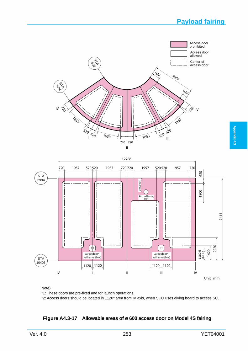
Payload fairing
Ver. 4.0 253 YET04001
Ap
pen
dix
4.3
Note) *1: These doors are pre-fixed and for launch operations. *2: Access doors should be located in ±120º area from IV axis, when SCO uses diving board to access SC.
Figure A4.3-17 Allowable areas of ø 600 access door on Model 4S fairing
Unit : mm
Access doorprohibited
Access doorallowed
Center ofaccess door
II
I720 720
520 520
1653
520 520
1653
III16531653
720
STA2994
STA-892
620
920
IV IV
720
STA2994
720 520 720 720 520 7201957
12786
620
1900
2220
7414
195719571957 520
IVIIV II III
520
11201120
1420
11201120
11
80
.5(R
EF
)
Large door* (with air vent hole)
1 Large door* (with air vent hole)
1
STA10408
1400
(RE
F)
Air conditioninginlet
4086
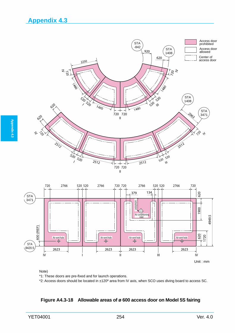
Appendix 4.3
YET04001 254 Ver. 4.0
Ap
pen
dix 4.3
Note) *1: These doors are pre-fixed and for launch operations. *2: Access doors should be located in ±120º area from IV axis, when SCO uses diving board to access SC.
Figure A4.3-18 Allowable areas of ø 600 access door on Model 5S fairing
4949
.5
2512 2512
2512
520520
III
520 520I
720 720II
720 720
IV IV
STA-842
920
620
STA1408
Access doorprohibited
Access doorallowed
Center ofaccess door
2250
620
620
STA1408
STA3471
720 720II
720 720
520 520I 520 520
III
IV IV
Unit : mm
2063
STA3471
II III IVIIV
379
2623 26232623 2623
620
620
1720
STA8420.5
1900
134
520520720 520520720720 7202766276627662766
Air vent hole
Air conditioninginlet
Air vent hole Air vent holeAir vent hole
2512
60
0 (
RE
F)
1400
(RE
F)
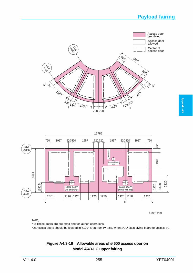
Payload fairing
Ver. 4.0 255 YET04001
Ap
pen
dix
4.3
Note) *1: These doors are pre-fixed and for launch operations. *2: Access doors should be located in ±120º area from IV axis, when SCO uses diving board to access SC.
Figure A4.3-19 Allowable areas of ø 600 access door on
Model 4/4D-LC upper fairing
Unit : mm
II
I720 720
520 520
1653
520 520
1653
III16531653
720
620
920 4086
IV IV
720
5414
720 520 720 720 520 7201957
12786
620
190
0
2220
195719571957 520
IVIIV II III
520
11201120127012701270
1420
127011201120
1180
.5
Access doorprohibited
Access doorallowed
Center ofaccess door
Air conditioninginlet
Large door* (with air vent hole)
1 Large door* (with air vent hole)
1
STA4408
STA-1006
STA
-4892
STA
-1006
1400
(RE
F)
1220
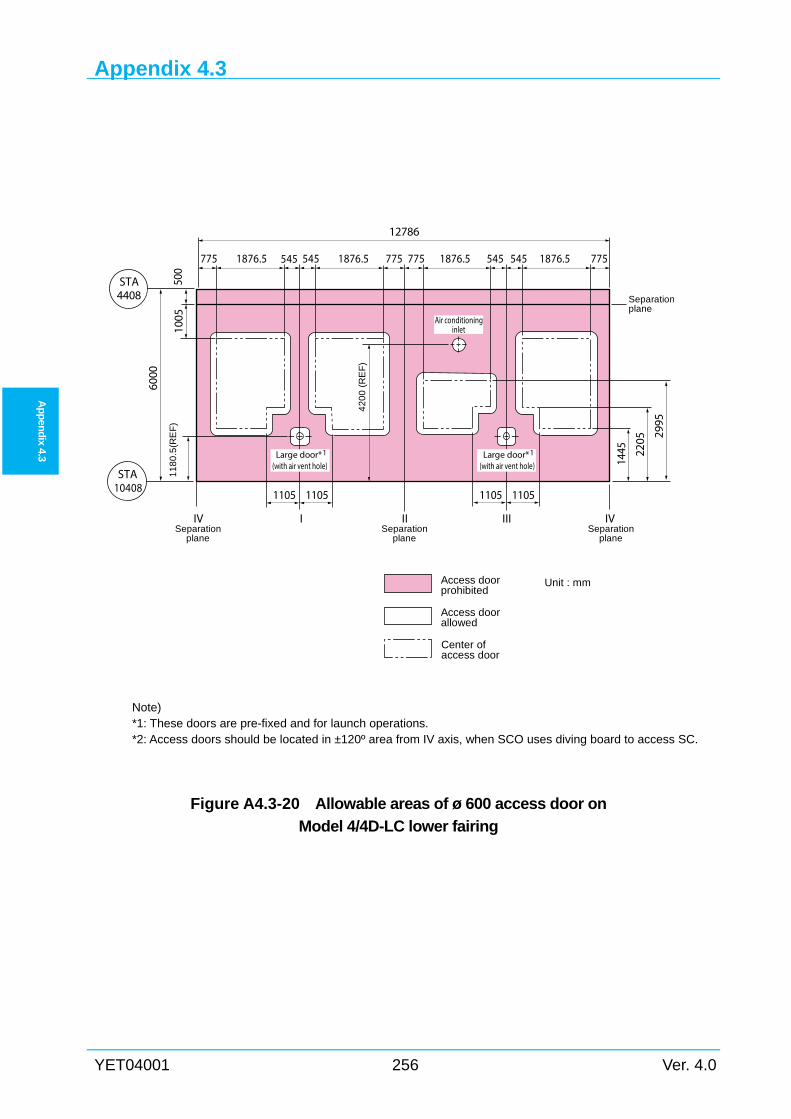
Appendix 4.3
YET04001 256 Ver. 4.0
Ap
pen
dix 4.3
Note) *1: These doors are pre-fixed and for launch operations. *2: Access doors should be located in ±120º area from IV axis, when SCO uses diving board to access SC.
Figure A4.3-20 Allowable areas of ø 600 access door on
Model 4/4D-LC lower fairing
STA4408
1005
STA10408
6000
1445
Access doorprohibited
Access doorallowed
Unit : mm
Center ofaccess door
2205
11
80
.5(R
EF
)
2995
IVIIV II III
1105110511051105
775 545 775 775
12786
1876.51876.51876.5 545 545 7751876.5545
500
Large door* (with air vent hole)
1
Air conditioninginlet
Large door* (with air vent hole)
1
42
00
(R
EF
)
Separationplane
Separationplane
Separationplane
Separationplane
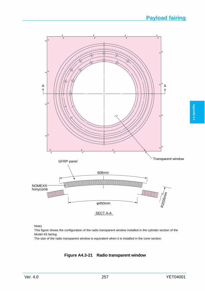
Payload fairing
Ver. 4.0 257 YET04001
Ap
pen
dix
4.3
Note) This figure shows the configuration of the radio transparent window installed in the cylinder section of the Model 4S fairing. The size of the radio transparent window is equivalent when it is installed in the cone section.
Figure A4.3-21 Radio transparent window
A A
GFRP panel
608mm
Transparent window
NOMEX®honycomb
φ450mm
SECT A-A
R20
35m
m
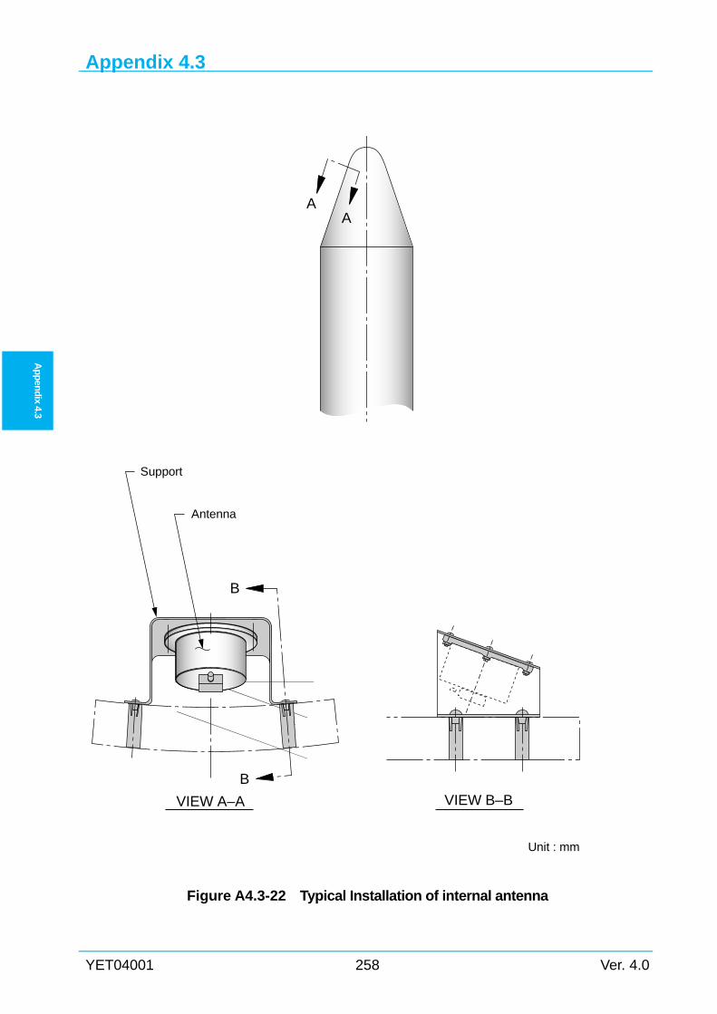
Appendix 4.3
YET04001 258 Ver. 4.0
Ap
pen
dix 4.3
Figure A4.3-22 Typical Installation of internal antenna
AA
B
B
VIEW A–A
Support
Antenna
VIEW B–B
Unit : mm
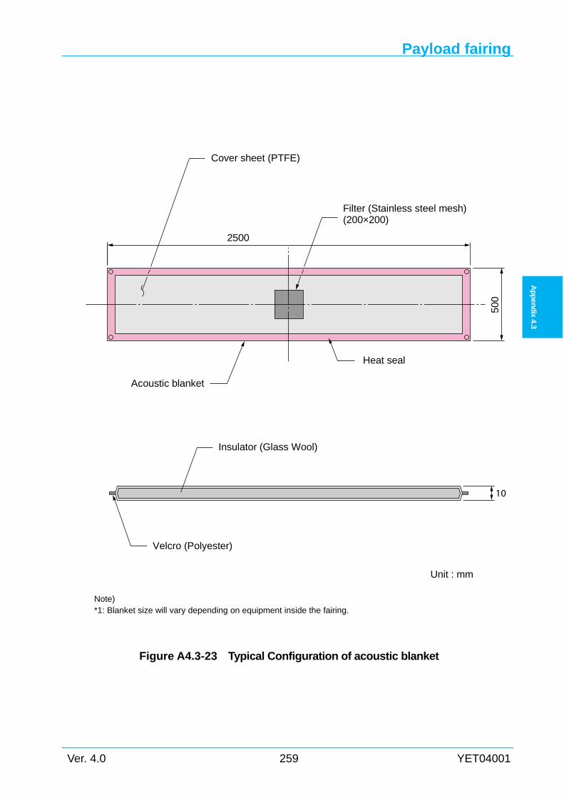
Payload fairing
Ver. 4.0 259 YET04001
Ap
pen
dix
4.3
Note) *1: Blanket size will vary depending on equipment inside the fairing.
Figure A4.3-23 Typical Configuration of acoustic blanket
1050
0
Velcro (Polyester)
Insulator (Glass Wool)
Acoustic blanket
Heat seal
Cover sheet (PTFE)
Filter (Stainless steel mesh)(200×200)
Unit : mm
2500
Appendix 4.3
YET04001 260 Ver. 4.0
Ap
pen
dix 4.3
Intentionally blank