Embed Size (px)
Citation preview
Filename, 1 Filename, 1 Blair Gohl SEABC - Soil-Structure Interaction 25-26 June 2010
The Structural Engineers Association of British Columbia
A technical seminar about modeling soil-structure interaction in the analysis of buildings and bridges, and how the design of structures is affected by the
incorporation of SSI effects.
Soil-Structure Interaction
Vancouver, BC
Soil-Structure Interaction of Piled Foundations for Buildings
Blair Gohl
AMEC Earth & Environmental , Burnaby, B.C. Guoxi Wu
BC Hydro, Burnaby, B.C.
Filename, 2 Filename, 2 Blair Gohl SEABC - Soil-Structure Interaction 25-26 June 2010
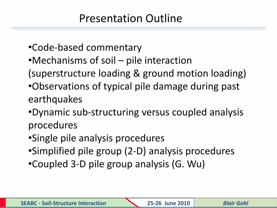
•Code-based commentary •Mechanisms of soil – pile interaction (superstructure loading & ground motion loading) •Observations of typical pile damage during past earthquakes •Dynamic sub-structuring versus coupled analysis procedures •Single pile analysis procedures •Simplified pile group (2-D) analysis procedures •Coupled 3-D pile group analysis (G. Wu)
Presentation Outline
Filename, 3 Filename, 3 Blair Gohl SEABC - Soil-Structure Interaction 25-26 June 2010
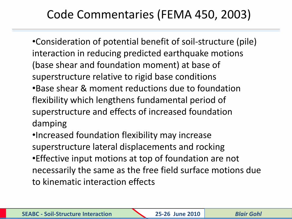
Code Commentaries (FEMA 450, 2003)
•Consideration of potential benefit of soil-structure (pile) interaction in reducing predicted earthquake motions (base shear and foundation moment) at base of superstructure relative to rigid base conditions •Base shear & moment reductions due to foundation flexibility which lengthens fundamental period of superstructure and effects of increased foundation damping •Increased foundation flexibility may increase superstructure lateral displacements and rocking •Effective input motions at top of foundation are not necessarily the same as the free field surface motions due to kinematic interaction effects

Filename, 4 Filename, 4 Blair Gohl SEABC - Soil-Structure Interaction 25-26 June 2010
Code Commentaries (FEMA 450, 2003)
•Pile foundations shall be designed and constructed to withstand maximum curvatures from earthquake ground motions (KI) and superstructure inertia loading •The effects of increased lateral ground deformation due to soil liquefaction or slope effects on pile foundations shall be considered •Ground improvement may be required to reduce seismic ground movements and effects on piles •Pile group interaction effects shall be considered •Detailed analysis of forces and moments developed in batter pile groups and pile cap connection details needs to be carried out
Filename, 5 Filename, 5 Blair Gohl SEABC - Soil-Structure Interaction 25-26 June 2010
Code Commentaries (FEMA 450, 2003)
•Pile foundations are to be designed as ductile structural elements but FEMA implies inelastic behavior is permissible as long as don’t have plastic hinging •Piles to remain functional following design earthquake in view of difficulties of repairing pile foundations •High bending moments and shears at pile cap – pile interface due to inertial interaction and near surface soil liquefaction effects •Potential for high moments and shears due to sharp transitions in lateral ground movement at larger depths, particularly at interfaces between stiff and soft soil layers

Filename, 6 Filename, 6 Blair Gohl SEABC - Soil-Structure Interaction 25-26 June 2010
Code Commentaries (FEMA 450, 2003)
•Superstructure – pile foundation interaction may be modeled using nonlinear load-deformation or moment-rotation relationships •Parametric studies required to examine sensitivity of superstructure and pile foundation response to nonlinear foundation stiffness parameters •Soil moduli and strengths used in foundation stiffness calculations should be based on ground strain levels and pore water pressures induced under design levels of seismic shaking

Filename, 7 Filename, 7 Blair Gohl SEABC - Soil-Structure Interaction 25-26 June 2010
NBCC, 2005 – Structural Commentary J
•Pile foundations required to resist the lateral load capacity of the Seismic Force Resisting System with suitable reductions in transmitted foundation load due to structure over-strength and ductility factors •Design foundations to continue to behave elastically following design earthquake for low to moderate eq. shaking with no soil liquefaction effects – see comments below) •Foundation design to take into account seismically induced ground strains and/or soil liquefaction effects without undergoing excessive foundation displacements – may require ground improvement to ensure this

Filename, 8 Filename, 8 Blair Gohl SEABC - Soil-Structure Interaction 25-26 June 2010
NBCC, 2005 – Structural Commentary J
•In regions of high seismicity (Ie Fa Sa (0.2) > 0.75), pile foundation elements to be designed to accommodate cyclic inelastic behavior for high moments > 0.75 Mult
•Use structural resistance factors for calculation of pile moment and shear capacity depending on material type •For strong earthquake shaking and where liquefaction effects occur, inelastic bending response of the piles is permitted as long as they can continue to carry axial dead plus live load following the earthquake •Piles must behave in a ductile fashion during strong eq. shaking and must not fail in shear

Filename, 9 Filename, 9 Blair Gohl SEABC - Soil-Structure Interaction 25-26 June 2010
Soil-Pile Superstructure Interaction
• Superstructure inertia loading at tops of piles (generally dominates over depth of about 10-15 pile diameters)
Filename, 10 Filename, 10 Blair Gohl SEABC - Soil-Structure Interaction 25-26 June 2010
Soil-Pile Superstructure Interaction
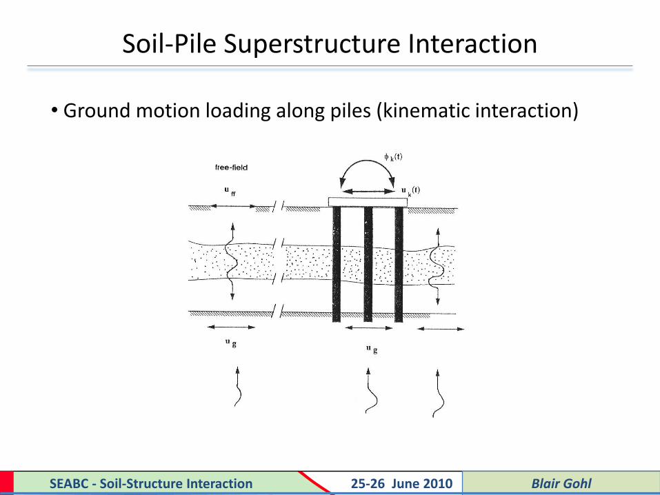
• Ground motion loading along piles (kinematic interaction)
Filename, 11 Filename, 11 Blair Gohl SEABC - Soil-Structure Interaction 25-26 June 2010
Theoretical KI Effects – G. Gazetas (1984)
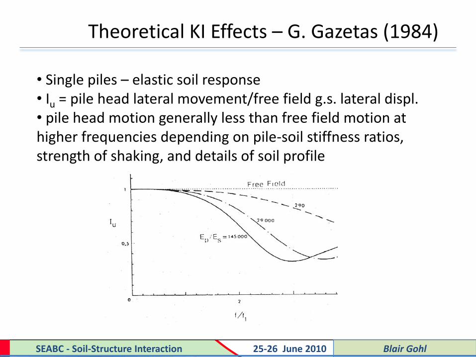
• Single piles – elastic soil response • Iu = pile head lateral movement/free field g.s. lateral displ. • pile head motion generally less than free field motion at higher frequencies depending on pile-soil stiffness ratios, strength of shaking, and details of soil profile

Filename, 12 Filename, 12 Blair Gohl SEABC - Soil-Structure Interaction 25-26 June 2010
Measured KI Effects – Tazoh et al (1988)
• Pile groups for a bridge foundation • Micro-tremor measurements • = ratio of effective pile cap motions to f.f. surface motions

Filename, 13 Filename, 13 Blair Gohl SEABC - Soil-Structure Interaction 25-26 June 2010
Considerations in Seismic Pile Design
• Effects of shaking on axial capacity and axial buckling (loss of shaft friction)
• Effects of shaking on post-seismic pile settlement
• Effects of pile head inertia forces (SS interaction) and imposed ground displacement (KI) on lateral bending and shear response
• Influence of pile foundations on combined stiffness and damping of superstructure – foundation system
Filename, 14 Filename, 14 Blair Gohl SEABC - Soil-Structure Interaction 25-26 June 2010
Damage Reports During Strong Shaking
• Effects of near surface soil liquefaction results in loss of lateral soil resistance, increased lateral pile displacements, and possible pile breakage due to SS inertia forces •Soil liquefaction effects along pile shafts leads to loss of axial capacity and increased post-seismic settlement – bearing capacity failures have been reported for soil liquefaction under pile bases
• Large lateral displacement gradients at transition between stiff and soft (liquefied??) soil layers results in damaging bending and shear in piles – check influence of lateral movements of stiff crust on top of liquefied layer

Filename, 15 Filename, 15 Blair Gohl SEABC - Soil-Structure Interaction 25-26 June 2010
Damage Reports During Strong Shaking
• Effects of seismically induced slope or river bank movements on pile bending response and lateral pile movements (e.g. Niigata eq. bridge failures supported on piles in liquefied soil)
• If the soil does not fail, bending damage governed by pile ductility – maximum curvatures just below pile cap for fixed head piles or slightly deeper locations for pinned head piles (SS loads), and where rapid changes in soil modulus occur (KI effects)
• Use of batter pile groups may decrease seismic lateral pile cap movements but need to check pile cap punching shear and tendency for rotation of pile caps

Filename, 16 Filename, 16 Blair Gohl SEABC - Soil-Structure Interaction 25-26 June 2010
General Guidelines for Pile Design
• Prevent soil liquefaction near pile head or else design for it
• Prevent large lateral ground movements acting on piles (slope effects, imbalanced fill loads) – ground improvement may be required
• Check effects of loss of shaft friction or pile tip capacity (loss of shaft friction due to free field pwp build-up and cyclic reversals of near field shear stresses)
• Use ductile piles (steel pipe, timber piles) where possible

Filename, 17 Filename, 17 Blair Gohl SEABC - Soil-Structure Interaction 25-26 June 2010
General Procedures in Seismic SS – Pile Analysis
• Geotechnical site characterization
• Static pile foundation design to reduce building settlements
• Free field site response analysis (simplified or using wave propagation models)
• Is soil liquefaction an issue and is there potential for large lateral ground movement acting on piles?

Filename, 18 Filename, 18 Blair Gohl SEABC - Soil-Structure Interaction 25-26 June 2010
General Procedures in Seismic SS – Pile Analysis
• Assessment of “effective” seismic motions acting at base of superstructure
• Conservative to use free field motions from 2005 NBCC for a particular site class, or site-specific seismic response analysis (SHAKE, DESRA, FLAC, etc.) for single piles
• KI effects may be more pronounced for pile groups than for single piles and use of FF motions may be un-conservative for longer period motions (G. Wu)

Filename, 19 Filename, 19 Blair Gohl SEABC - Soil-Structure Interaction 25-26 June 2010
General Procedures in Seismic SS – Pile Analysis
• Is a rigid base SS analysis to be performed using “effective” or “free field” seismic input motions?
• Is a flexible base SS analysis to be performed using an uncoupled analysis procedure and foundation compliances? Is this an equivalent linear modal analysis, or a nonlinear time step analysis?
• Is a fully coupled SS – pile foundation to be performed where seismic ground motions are propagated at depth up through the piles?

Filename, 20 Filename, 20 Blair Gohl SEABC - Soil-Structure Interaction 25-26 June 2010
KI Analysis of Single Piles
• Most common practice is to use numerical finite element or finite difference models of a beam on a nonlinear Winkler foundation to represent near field soil-pile interaction
• Closed form analytic expressions for KI effects (e.g. Gazetas) are generally based on linear elastic soil response and have limited applicability for strong shaking
• Input free field, lateral ground displacement time histories Uff (z,t) at ends of springs where Uff (z,t) derived from nonlinear site response analysis (SHAKE, DESRA, FLAC, etc.)

Filename, 21 Filename, 21 Blair Gohl SEABC - Soil-Structure Interaction 25-26 June 2010
KI Analysis of Single Piles
• Single pile analysis with support motion model • no pile head mass for KI analysis • soil radiation damping parameters important • near field soil-pile interaction described using p-y curves

Filename, 22 Filename, 22 Blair Gohl SEABC - Soil-Structure Interaction 25-26 June 2010
KI Analysis of Single Piles
• stiff piles in softer soils attenuate higher frequency motions
• consider KI effects for larger diam. piles with f > 1.5 f1 (Gazetas)
Low Frequency Ground Motion Input
-0.100
-0.050
0.000
0.050
0.100
0.150
0.0 5.0 10.0 15.0 20.0 25.0 30.0 35.0 40.0
Time (seconds)
Ho
riz
. A
bso
lute
Dis
pl. (
m)
Grd. surface free field Top of caisson
High Frequency Ground Motion Input
-0.100
-0.050
0.000
0.050
0.100
0.150
0.0 1.0 2.0 3.0 4.0
Time (seconds)
Ho
riz
. A
bs
olu
te D
isp
l.
(m)
Grd. surface free field Top of caisson

Filename, 23 Filename, 23 Blair Gohl SEABC - Soil-Structure Interaction 25-26 June 2010
Near Field Soil-Pile Interaction (Lateral)
• P-y curves derived from static and cyclic pile head loading tests for various soil types (reference API) but not calibrated for seismic loading conditions at larger depths • Backbone P-y curves at larger depths typically based on plasticity theory relating ultimate lateral soil capacity to a translating disc (pile) with initial slope of P-y curve derived from elasticity theory – hysteretic behavior simulated using various load-unload rules • Complications in P-y curve modeling to account for soil-pile separation (near soil surface) and softening of P-y curve with time due to cyclic pore pressure generation • Common to look at pre- and post-earthquake P-y backbone curves to look at sensitivity of response

Filename, 24 Filename, 24 Blair Gohl SEABC - Soil-Structure Interaction 25-26 June 2010
Near Field Soil-Pile Interaction (Lateral)
• Cyclic P-y curves in soft clay (a) zone of unconfined response and (b) zone of confined response (R. Bea, 1980)

Filename, 25 Filename, 25 Blair Gohl SEABC - Soil-Structure Interaction 25-26 June 2010
Near Field Soil-Pile Interaction (Lateral)
• Cyclic P-y curves in dry sand (Gohl, 1991)

Filename, 26 Filename, 26 Blair Gohl SEABC - Soil-Structure Interaction 25-26 June 2010
Near Field Soil-Pile Interaction (Lateral)
• Cyclic P-y curves in loose saturated sand (Yao and Kobayashi, 1992)

Filename, 27 Filename, 27 Blair Gohl SEABC - Soil-Structure Interaction 25-26 June 2010
Near Field Soil-Pile Interaction (Axial)
• T-z curves represent soil resistance along pile shaft versus relative axial pile deflection • Backbone Q-z curves represent soil resistance at pile tip versus relative pile tip deflection • Backbone T-z and Q-z curves derived from load test data and theory for cohesive and cohesionless soils (Reese et al, 2006) • Account for cyclic axial behaviour using various load-unload rules • Where cyclic pore pressure generation occurs along the pile during shaking need to account for this by cyclically degrading the backbone T-z or Q-z curves or else bound axial pile response using pre-earthquake and post-earthquake curves

Filename, 28 Filename, 28 Blair Gohl SEABC - Soil-Structure Interaction 25-26 June 2010
Uncoupled Seismic Analysis of Single Piles
• Consider response of broadly spaced piles (s/d > 6)
• Objective is to determine pile stresses in response to SS inertia loads and imposed lateral ground displacements
• Use uncoupled SS analysis to determined pile head loads and influence of SS inertia forces on single piles
• Where effects of lateral soil displacement at depth on pile bending is important, need to do coupled SS – pile analysis considering both inertial and KI loading

Filename, 29 Filename, 29 Blair Gohl SEABC - Soil-Structure Interaction 25-26 June 2010
Uncoupled Seismic Analysis of Single Piles
•For uncoupled superstructure analysis require pile head lateral, vertical and rotational stiffness parameters with nonlinear soil-pile interaction represented using P-y and T-z curves (programs LPILE and APILE developed by Ensoft)
• Compute nonlinear lateral, rotational and vertical load-deflection (moment-rotation) curves at pile head
•For uncoupled modal analysis use equivalent linear, secant stiffness at an effective pile head displacement level and iterate on solution
• For uncoupled time step analysis use nonlinear pile head force-displacement (moment-rotation) curves

Filename, 30 Filename, 30 Blair Gohl SEABC - Soil-Structure Interaction 25-26 June 2010
Uncoupled Seismic Analysis of Single Piles
• Uncoupled superstructure – pile model using nonlinear time step analysis • Objective is to calculate pile head forces and moments at ground surface and do separate analysis of pile bending response due to SS inertia loads

Filename, 31 Filename, 31 Blair Gohl SEABC - Soil-Structure Interaction 25-26 June 2010
Uncoupled Seismic Analysis of Single Piles
• Consider variation in pile head stiffness (Kuu , Krr and Kur) with lateral pile head deflection relative to free field ground surface deflection • Use pile head viscous dashpots to represent far field radiation damping and near field hysteretic damping

Filename, 32 Filename, 32 Blair Gohl SEABC - Soil-Structure Interaction 25-26 June 2010
Uncoupled Seismic Analysis of Single Piles
• Results

Filename, 33 Filename, 33 Blair Gohl SEABC - Soil-Structure Interaction 25-26 June 2010
Uncoupled Seismic Analysis of Single Piles
• From uncoupled SS-pile analysis compute pile head moments and shears and do lateral pile bending analysis, assuming dominated by SS inertia

Filename, 34 Filename, 34 Blair Gohl SEABC - Soil-Structure Interaction 25-26 June 2010
Uncoupled Seismic Analysis of Single Piles
• Key input is effective ground motions transmitted to base of pile cap and pile head stiffness/damping parameters • Require good prediction of natural frequency of superstructure – pile foundation system which varies during shaking due to nonlinear pile head compliances • Use computed pile head moments and shears to assess pile bending response during shaking based solely on SS inertia loading • Where lateral ground displacements impose significant loading on pile, perform coupled SSI analysis

Filename, 35 Filename, 35 Blair Gohl SEABC - Soil-Structure Interaction 25-26 June 2010
Coupled Seismic Analysis of Single Piles
• Simplified pseudo-static analysis using LPILE or LATPILE where apply maximum pile head moments and shears concurrently with maximum Uff (z) at some time during or after shaking
• Maximum pile head loading may not occur at same time as maximum Uff
• Neglect resistance due to pile inertia and soil damping – generally leads to over-prediction of pile bending response
• Preferable to do dynamic coupled analysis

Filename, 36 Filename, 36 Blair Gohl SEABC - Soil-Structure Interaction 25-26 June 2010
Coupled Seismic Analysis of Single Piles
• Method 1 - Beam on nonlinear Winkler springs with soil radiation damping and imposed Uff (z,t) – key input is Uff from separate FF site response analysis • Method 2 – Beam (linear or nonlinear structural response) on nonlinear Winkler springs to represent near field response connected to FE or FD mesh representing nonlinear far field response • In Method 2 radiation damping automatically accounted for • In Method 2 generally employ 2-D plane strain model of far field soil response and need to employ 2-D beam elements with I = t3/12 and A = t x 1.0 • Calibrate 2-D far field response to approximately match 1-D site response results where level ground conditions occur

Filename, 37 Filename, 37 Blair Gohl SEABC - Soil-Structure Interaction 25-26 June 2010
Coupled Seismic Analysis of Single Piles
• Method 1 example (beam on nonlinear Winkler foundation in dry sand – centrifuge test data using SHAKE free field motions)

Filename, 38 Filename, 38 Blair Gohl SEABC - Soil-Structure Interaction 25-26 June 2010
Coupled Seismic Analysis of Single Piles
• General experience with Method 1 approach Results sensitive to input Uff (z,t) – use of equivalent linear SHAKE model generally under-predicts ground displacements and should use nonlinear site response models for strong shaking Locations of maximum moment strongly depends on p-y curves used and resultant lateral soil stiffness versus depth Frequency content of pile response (displacements, moments, shears) simulated well provided have accurate Uff time history input

Filename, 39 Filename, 39 Blair Gohl SEABC - Soil-Structure Interaction 25-26 June 2010
Coupled Seismic Analysis of Single Piles
• Method 2 example (imbalanced fill loads on existing timber piles in liquefiable fill over soft peat and clayey silt • Pile cap constrained laterally • Neglect pile group interaction effects • Large lateral ground displ. in liq. fill and peat

Filename, 40 Filename, 40 Blair Gohl SEABC - Soil-Structure Interaction 25-26 June 2010
Coupled Seismic Analysis of Single Piles
• Method 2 results Ground displacement loading dominates pile response Highest bending moment and curvatures near underside of pile cap with 0.06 (near limit for timber piles)

Filename, 41 Filename, 41 Blair Gohl SEABC - Soil-Structure Interaction 25-26 June 2010
Uncoupled Inertial Analysis of Pile Groups
• Require equivalent linear or nonlinear force-displacement or moment rotation relations at pile cap level to be used in equivalent linear or nonlinear inertial interaction analysis
• Most commonly used program for nonlinear response (strong shaking) is GROUP (Ensoft)
• Program based on FE discretization of linear elastic beam elements on nonlinear Winkler springs (lateral and axial response) developed from P-y, T-Z and Q-Z curves
• Stress overlap effects between closely spaced piles (group interaction effects) approximately modeled using user-defined P-y and T-Z curve multipliers

Filename, 42 Filename, 42 Blair Gohl SEABC - Soil-Structure Interaction 25-26 June 2010
General Commentary of Group Interaction
• Interaction strongest for inline loading of piles (trailing piles) and reduced interaction for offline loading
• Linear elastic models of group interaction have less applicability for moderate to strong shaking where plastic yield of soil around piles dominates
• Continue to use elastic models of GI for small strain dynamic excitation of piles (machine foundations) embedded in programs like DYNA5 – GI shows strong frequency effects due to out of phase motions of pile vibrations within a group

Filename, 43 Filename, 43 Blair Gohl SEABC - Soil-Structure Interaction 25-26 June 2010
P-Y Curve Multipliers
• Typical multipliers suggested by Reese et al (2006), “Analysis and Design of Shallow and Deep Foundations” for inline and offline interaction • Multipliers depend on pile spacing and locations of piles in group – should be selected by a qualified geotechnical engineer

Filename, 44 Filename, 44 Blair Gohl SEABC - Soil-Structure Interaction 25-26 June 2010
2-D Coupled Model of Pile Group Response
• In plane representation of a typical line of piles with accounting for out of plane spacing S of piles to get equivalent 2-D representation of pile structural properties
• Model near field soil-pile interaction using nonlinear lateral and axial springs, connected to adjacent soil nodes in FE or FD mesh
• Do parametric studies with and without GI effects on scaling of near field interaction springs
• Couple far field ground displacement response to pile group

Filename, 45 Filename, 45 Blair Gohl SEABC - Soil-Structure Interaction 25-26 June 2010
2-D Coupled Model of Pile Group Response
• Example using program LSDYNA with following features: Concrete batter pile group with nonlinear moment-curvature relation and pinned head connections Nonlinear soil stress-strain response with softening due to pwp build-up & use of lightweight EPS fill Near field nonlinear lateral and axial springs using GI multipliers on lateral springs

Filename, 46 Filename, 46 Blair Gohl SEABC - Soil-Structure Interaction 25-26 June 2010
2-D Coupled Model of Pile Group Response
• Key conclusions: Modeling nonlinear free field soil response with non-level ground effects, including pwp build-up, very important in assessing dominant loading on pile group Modeling structural response of piles (nonlinear moment curvature, pinned head connections) very important to indicate zones where plastic yield occurs and whether axial buckling could occur Near field soil-pile interaction, including GI, important in simulating maximum lateral pressures that can be applied to a pile in the group

Filename, 47 Filename, 47 Blair Gohl SEABC - Soil-Structure Interaction 25-26 June 2010
Approximate 3-D Model of Pile Group Response

Filename, 48 Filename, 48 Blair Gohl SEABC - Soil-Structure Interaction 25-26 June 2010 Guoxi Wu
=
ar
P, S waves
R, L waves
ast
Mass free
ar
P, S waves
R, L waves
ast
Mass free
macinmacin
+
Kinematic Interactions: -Foundation input motions -Pile stresses (moments etc) -Impedance values
Inertial Interaction on piles: - Pile/cap stresses - Pile/cap deflections
Response of Structures on Piled Foundations: Kinematic Interactions + Inertial Interaction
Acknowledgement to Dr. Rosa M.S. Maiorano

Filename, 49 Filename, 49 Blair Gohl SEABC - Soil-Structure Interaction 25-26 June 2010 Guoxi Wu
Response of Structures on Piled Foundations: Current methods of analysis and design
Tools: 1. Analytical solutions,
empirical methods 2. VERSAT-P3D finite
element method
Tools: 1. FIM = free field motions (ProShake, VERSAT-
2D, FLAC?) 2. Kinematic stresses ignored 3. Pile cap impedance, DYNA5 (interaction
factors), VERSAT-P3D 4. Lateral single pile analyses LPILE, VERSAT-
P3D 5. Pile Group Analysis (GROUP using p-
multipliers, & VERSAT-P3D)
Kinematic Interactions: - Foundation input motions (FIM) - Pile stresses (moments etc) - Impedance values
Inertial Interaction on piles: - Pile/cap stresses - Pile/cap deflections
To be addressed, Eurocode 8 (2003), Italian building code (2008)

Filename, 50 Filename, 50 Blair Gohl SEABC - Soil-Structure Interaction 25-26 June 2010 Guoxi Wu
Bedrock
free-field
Horizontal
displacement of soil
at time t
Deflection profile
of the pile at time t
Kinematic Response of Pile Foundations: kinematic deflections & bending moments along the piles

Filename, 51 Filename, 51 Blair Gohl SEABC - Soil-Structure Interaction 25-26 June 2010 Guoxi Wu
Kinematic Response of Pile Foundations: Seismic motions at the pile head / pile cap
Bedrock
free-field
The presence of piles
MODIFIES the Foundation
Input Motion (FIM) at the
base of the structure

Filename, 52 Filename, 52 Blair Gohl SEABC - Soil-Structure Interaction 25-26 June 2010 Guoxi Wu
Kinematic Response: Quasi-3D Finite Element Method of Analysis
zG +
yG +
xG =
t2
2*
2
2*
2
2*
2
2
s
Equations of Motions (Wu and Finn 1997):
References: Wu, G., and Finn, W.D.L. 1997a. Dynamic elastic analysis of pile foundations using finite element method in the frequency domain. Canadian Geotechnical Journal, 34: 34-43 Wu, G., and Finn, W.D.L. 1997b. Dynamic nonlinear analysis of pile foundations using finite element method in the time domain. Can Geot J, 34: 44-52
Features: 1. Solutions in frequency domain for impedance (stiffness and damping) calculation 2. Solutions in time-domain for non-linear time history analyses of piled foundations under earthquake loadings 3. Superstructures are represented by a rigid pile cap with masses in translation and rotation. 4. Equivalent linear procedures for modeling soil nonlinearity.

Filename, 53 Filename, 53 Blair Gohl SEABC - Soil-Structure Interaction 25-26 June 2010 Guoxi Wu
Kinematic Response: Quasi-3D Finite Element Method of Analysis
Nonlinear modeling: - Seed’s equivalent linear procedure
modified for time-history analyses, i.e., G and l vary with shear strain (g) in the time domain.
- User defined curves for G/Gmax and l
(figures on the right as an example)
New enhancements - 8-node pile element
- energy boundary for radiation damping at boundaries.
cs = ∫A ρ Vs dA for shearing
cp = ∫A ρ Vp dA for compression
- Incorporated in the program VERSAT-P3D (Wu 2006)

Filename, 54 Filename, 54 Blair Gohl SEABC - Soil-Structure Interaction 25-26 June 2010 Guoxi Wu
Normalized horizontal stiffness of single piles (Source: Wu 2007 60th Can. Geot. Conference)
Ep/Es=1000, µ=0.4, λ=5%, L/d=15
0
2
4
6
8
10
12
0.0 0.1 0.2 0.3 0.4 0.5 0.6 0.7 0.8 0.9 1.0
Dimensionless frequency, a0 = ω.d/Vs
Norm
aliz
ed S
tiff
ness,
k y
y/E
sd this study for d=0.3 m, standard 8x24 grid w ith Ymax=26m
this study for d=0.3 m, 9x18 grid for high frequency, equal spacing 0.5 m
this study for d=0.76 m, standard 8x24 grid w ith Ymax=68m
this study for d=0.76 m, 9x18 grid for high frequency, equal spacing 1.5 m
Kaynia and Kausel (1982)
Wu and Finn (1997a)
Quasi-3D Method: Verification with Solutions by Kaynia and Kausel

Filename, 55 Filename, 55 Blair Gohl SEABC - Soil-Structure Interaction 25-26 June 2010 Guoxi Wu
Quasi-3D Method: Verification with Solutions by Kaynia and Kausel
Ep/Es=1000, µ=0.4, λ=5%, L/d=15
0
5
10
15
20
25
30
0.0 0.1 0.2 0.3 0.4 0.5 0.6 0.7 0.8 0.9 1.0
Dimensionless frequency, a0 = ω.d/Vs
Norm
aliz
ed S
tiff
ness,
k z
z/ E
sd this study for d=0.3 m, standard 8x24 grid w ith Ymax=26m
this study for d=0.3 m, 9x18 grid for high frequency, equal spacing 0.5 m
this study for d=0.76 m, standard 8x24 grid w ith Ymax=68m
this study for d=0.76 m, 9x18 grid for high frequency, equal spacing 1.5 m
Kaynia and Kausel (1982)
Normalized vertical stiffness of single piles

Filename, 56 Filename, 56 Blair Gohl SEABC - Soil-Structure Interaction 25-26 June 2010 Guoxi Wu
Quasi-3D Method: Verification with Solutions by Kaynia and Kausel
2x2 pile group: Horizontal stiffness
(Source: Wu 2007 60th Can. Geot. Conference)
2x2 Group: Ep/Es=1000, s/d=5, L/d=15
0
1
2
3
0.0 0.1 0.2 0.3 0.4 0.5 0.6 0.7 0.8 0.9 1.0
Dimensionless frequency, a0 = ω.d/Vs
Gro
up F
acto
r, α
yy
this study for d=0.3 m, standard 10x28 grid with Ymax=27.5 m
this study for d=0.3 m, 11x22 grid for high frequency, equal spacing 0.5 m
this study for d=0.76 m, standard 10x28 grid with Ymax=72 m
this study for d=0.76 m, 11x22 grid for high frequency, equal spacing 1.5 m
Kaynia and Kausel (1982)
Wu and Finn (1997a)

Filename, 57 Filename, 57 Blair Gohl SEABC - Soil-Structure Interaction 25-26 June 2010 Guoxi Wu
Quasi-3D Method: Verification with Solutions by Kaynia and Kausel
2x2 Group: Ep/Es=1000, s/d=5, L/d=15
-1
0
1
2
3
4
5
6
7
0.0 0.1 0.2 0.3 0.4 0.5 0.6 0.7 0.8 0.9 1.0
Dimensionless frequency, a0 = ω.d/Vs
Gro
up F
ac
tor,
α z
z
this study for d=0.3 m, standard 10x28 grid with Ymax=27.5 m
this study for d=0.3 m, 11x22 grid for high frequency, equal spacing 0.5 m
this study for d=0.76 m, standard 10x28 grid with Ymax=72 m
this study for d=0.76 m, 11x22 grid for high frequency, equal spacing 1.5 m
Kaynia and Kausel (1982)
2x2 pile group: Vertical stiffness

Filename, 58 Filename, 58 Blair Gohl SEABC - Soil-Structure Interaction 25-26 June 2010 Guoxi Wu
2x2 Group: Ep/Es=1000, s/d=5, L/d=15
0
1
2
3
4
5
6
7
8
9
10
11
12
0.0 0.1 0.2 0.3 0.4 0.5 0.6 0.7 0.8 0.9 1.0
Dimensionless frequency, a0 = ω.d/Vs
Dam
pin
g C
onsta
nts
, l
a0
this study for d=0.3 m, standard 10x28 grid with Ymax=27.5 mthis study for d=0.3 m, 11x22 grid for high frequency, equal spacing 0.5 mthis study for d=0.76 m, standard 10x28 grid with Ymax=72 mthis study for d=0.76 m, 11x22 grid for high frequency, equal spacing 1.5 mKaynia and Kausel (1982)d=0.3 m standardd=0.3 md=0.76 m standardd=0.76 mk&k
vertical
horizontal
2x2 pile group: Horizontal and vertical damping
Quasi-3D Method: Verification with Solutions by Kaynia and Kausel

Filename, 59 Filename, 59 Blair Gohl SEABC - Soil-Structure Interaction 25-26 June 2010 Guoxi Wu
Quasi-3D Method: Verification with centrifuge tests of piles
References: Finn, W.D.L., and Gohl, W.B. 1987. Centrifuge model studies of piles under simulated earthquake loading. Dynamic Response of Pile Foundations - Experiment, Analysis and Observation, ASCE Geotechnical Special Publication No. 11, pp. 21-38. Wu, G., and Finn, W.D.L. 1997b. Dynamic nonlinear analysis of pile foundations using finite element method in the time domain. Can Geot J, 34: 44-52
G/Gmax and l = f (g)
Pile head accelerations
Caltech centrifuge, 60g

Filename, 60 Filename, 60 Blair Gohl SEABC - Soil-Structure Interaction 25-26 June 2010 Guoxi Wu
Quasi-3D Method: Verification with centrifuge tests of piles
Bending moment at 3 m depth
Note:
Similar quasi-3D analyses were also conducted for a centrifuge test on a 2 x 2 pile group (Wu and Finn 1997).

Filename, 61 Filename, 61 Blair Gohl SEABC - Soil-Structure Interaction 25-26 June 2010 Guoxi Wu
Quasi-3D Method: Verification with in-situ load tests of pile groups
PC PilesBored Piles
B5 B9
B2 B8
B10
B6
P13 P12 P11 P10
P1
P2
P3
P5P6
P4P9
P8
H400 H500
Bored Pile Cap PC Pile CapG.L.
Jack & Load Cell
Bearing Plate
H300
0 2 4 6m
B7 B13
B4 B12 B3
B1 B11
P7
LVDT
LVDT
N
CPT-N1 CPT-N2
CPT-N1
SCPT-2
SCPT-1CPT-1
Test Piles and CPT Test Holes from Huang et al. (ASCE Geot J. 2001)
Item Bored piles PC piles
Diameter 1.5 m0.8 m OD, 0.56 m ID
With concrete infill
Length 34.9 m 34 m
Intact flexural
rigidity, EI6.86 x 106 kN.m2 0.79 x 10⁶ kN.m2

Filename, 62 Filename, 62 Blair Gohl SEABC - Soil-Structure Interaction 25-26 June 2010 Guoxi Wu
Quasi-3D Method: Verification with in-situ load tests of pile groups
• Quasi-3D finite element model used for the analysis of a 3x4 PC pile group

Filename, 63 Filename, 63 Blair Gohl SEABC - Soil-Structure Interaction 25-26 June 2010 Guoxi Wu
Quasi-3D Method: Verification with in-situ load tests of pile groups
Lateral load versus pile head deflection for pile groups
(Source: Wu 2007 60th Can. Geot. Conference)
0
2000
4000
6000
8000
10000
12000
0 20 40 60 80 100
Pile head lateral deflection, mm
Bored Pile Group: 2x3
s/d=3, d=1.5 m
0
2000
4000
6000
8000
10000
12000
0 20 40 60 80 100
Pile head lateral deflection, mm
Late
ral l
oad, kN
Computed using VERSAT-P3D
Measured by Huang et al. (2001)
PC Pile Group: 3x4
s/d=3, d=0.8 m
Conventional Method: P-y curves and P-multipliers back-calculated by Huang et al. (ASCE Geot J 2001) Single piles: pmulti= 0.21(PC), 0.50 (bored) Group piles from DMT data: pmulti (average) = 0.26 (PC piles), 0.37(bored) Group piles from load test data: pmulti (average) = 1.22 (PC piles), 0.75(bored)

Filename, 64 Filename, 64 Blair Gohl SEABC - Soil-Structure Interaction 25-26 June 2010 Guoxi Wu
Quasi-3D Method: Verification with in-situ load tests of pile groups
0
5
10
15
20
-20 0 20 40 60 80Deflection, mm
Depth
, m
P8, P9, P13
P4, P6, P12
P3, P5, P11
P1, P2, P10
computed using
VERSAT-P3D
PC Pile Group -7122 kN
Measured
Computed using
VERSAT-P3D
0
5
10
15
20
-10 0 10 20 30 40 50 60 70Deflection, mm
B2, B5
B8, B9
B6, B10
computed using
VERSAT-P3D
Bored Pile Group -10948 kN
Measured
Computed using
VERSAT-P3D

Filename, 65 Filename, 65 Blair Gohl SEABC - Soil-Structure Interaction 25-26 June 2010 Guoxi Wu
0
5
10
15
20
-1500 -1000 -500 0 500 1000 1500
Bending moment, kN.m
Depth
, m
lead row , side pile
lead row , centre pile
middle row , side pile
middle row , centre pile
PC Pile Group
- 7122 kN
0
5
10
15
20
-7000 -5000 -3000 -1000 1000 3000
Bending moment, kN.m
lead row
middle row
trail row
Bored Pile Group
- 10948 kN
Computed bending moments of piles versus depth for pile groups
Quasi-3D Method: Verification with in-situ load tests of pile groups

Filename, 66 Filename, 66 Blair Gohl SEABC - Soil-Structure Interaction 25-26 June 2010 Guoxi Wu
1. Vashon Drift - Glacial outwash or ice contact 2. Capilano Sediments - Marine clayey silt to silty clay 3. Fraser River Channel Deposits
Seismic Assessment for Pattullo Bridge, NW/Surrey,BC Owner: Greater Vancouver Transportation Authority (Translink) Consultants: Golder Associates, Sandwell and Hatch Mott MacDonald
Quasi-3D Method: Application Case History on the Pattullo Bridge
Pier 3 4 under the steel bridge section

Filename, 67 Filename, 67 Blair Gohl SEABC - Soil-Structure Interaction 25-26 June 2010 Guoxi Wu
VERSAT-P3D MODEL OF PIER 3 CAISSON (31.7 m by 10.7 m, 22 m deep)
- TRANSVERSE TO BRIDGE ALIGNMENT
Quasi-3D Method: Application Case History on the Pattullo Bridge

Filename, 68 Filename, 68 Blair Gohl SEABC - Soil-Structure Interaction 25-26 June 2010 Guoxi Wu
VERSAT-P3D MODEL OF PIER 4 CAISSON (31.7 m by 10.7 m, 20 m deep)
- Longitudinal to Bridge Alignment
Fraser River
sands
Marine clayey silt to silty clay
Very Dense Sands, Gravels at the base
Quasi-3D Method: Application Case History on the Pattullo Bridge

Filename, 69 Filename, 69 Blair Gohl SEABC - Soil-Structure Interaction 25-26 June 2010 Guoxi Wu
0
2000000
4000000
6000000
8000000
10000000
12000000
14000000
0 5 10 15 20 25 30 35 40 45 50
Time in Shaking (sec)
Ho
rizo
nta
l S
tiff
ne
ss
, K
xx
(k
N/m
)
CITEW - EQ5(475-yr)
OLNS - EQ8 (475-yr)
OLNS - EQ8 for Case 1
OLNS - EQ8 for Case 2
RECOMMENDED Average
PIER 4 HORIZONTAL STIFFNESS - Transverse
Transverse
0.00E+00
2.00E+06
4.00E+06
6.00E+06
8.00E+06
1.00E+07
1.20E+07
0 5 10 15 20 25 30 35 40 45 50
Time in Shaking (sec)
Ho
rizo
nta
l S
tiff
ne
ss
, K
yy
(k
N/m
)
OLEW - EQ1(475-yr)
CITNS - EQ2 (475-yr)
OLEW - EQ1 for Case 1
OLEW - EQ1 for Case 2
RECOMMENDED Average
PIER 4 HORIZONTAL STIFFNESS - LongitudinalLongitudinal VERSAT-P3D Results:
Horizontal Stiffness Time-history
of Pier 4 Caisson
Quasi-3D Method: Application Case History on the Pattullo Bridge Foundation Impedance Values (stiffness, damping)

Filename, 70 Filename, 70 Blair Gohl SEABC - Soil-Structure Interaction 25-26 June 2010 Guoxi Wu
Quasi-3D Method: Application Case History on the Pattullo Bridge Foundation Input Motions (FIM)
1/1000 ground motions (EQ3 LNNS): longitudinal
0.00
0.20
0.40
0.60
0.80
1.00
0.0 0.5 1.0 1.5 2.0 2.5 3.0
Period, T(sec)
Sp
ectr
al A
cce
lera
tio
ns (
g)
FIM @ Pier 4 (VERSAT-P3D)
F.F. @ Pier 4 (ProSHAKE)
1/1000 ground motions (EQ3 LNNS): longitudinal
0.00
0.20
0.40
0.60
0.80
1.00
0.0 0.5 1.0 1.5 2.0 2.5 3.0
Period, T(sec)
Sp
ectr
al A
cce
lera
tio
ns (
g)
FIM @ Pier 4
FIM @ Pier 3

Filename, 71 Filename, 71 Blair Gohl SEABC - Soil-Structure Interaction 25-26 June 2010 Guoxi Wu
Quasi-3D Method: Research case history for Eurocode 8 (2003) and Italian code (2008)
Eurocode 8: Design of structures for earthquake resistance by CEN/TC250 (European committee for standardization technical committee 250)
Italian code: Italian Building Code DM 14.01.2008
“kinematic effects have to be addressed for the performance evaluation of a piled foundation”
- Research group at the University of Napoli Parthenope, Naples, Italy, including Prof. S. Aversa, Dr. Rosa Maiorano, L. de Sanctis, &A. Mandolini
- In Canada: G. Wu
- Primary goal: kinematic bending moments between two layers & at pile head
- Primary tool: VERSAT-P3D (Wu 2006)
REFERENCES: -de Sanctis, L., Maiorano, R.M.S., Aversa, S. A method for assessing kinematic bending moments at the pile head, Earthquake Engineering and Structural Dynamics, vol. 39; p. 375-397, ISSN 0098-8847.
-de Sanctis, L., Maiorano, R.M.S. Earthquake induced kinematic bending moments. International Conference on Performance based design in earthquake geotechnical engineering, IS-Tokyo, Tsukuba, Japan, 15-17 June 2009.
-Maiorano, R.M.S., de Sanctis, L., Aversa, S., Mandolini, A. 2008. Kinematic response analysis of piled foundations under seismic excitation. Canadian Geotechnical Journal 46: 571 - 584
-Maiorano, R.M.S., Aversa, S., and Wu, G. 2007. Effects of soil non-linearity on bending moments in piles due to seismic kinematic interaction. Proceedings
of the 4th International Conference on Earthquake Geotechnical Engineering, Paper No. 1574, Thessaloniki, Greece.
Filename, 72 Filename, 72 Blair Gohl SEABC - Soil-Structure Interaction 25-26 June 2010 Guoxi Wu
Quasi-3D Method: Research case history for Eurocode 8 (2003) and Italian code (2008)
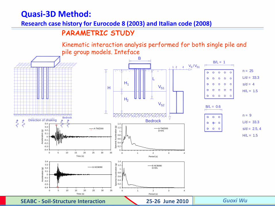
PARAMETRIC STUDY
Kinematic interaction analysis performed for both single pile and pile group models. Inteface
B/L = 1
s/d = 4
H/L = 1.5
L/d = 33.3
n = 25
s/d = 2.5, 4
H/L = 1.5
L/d = 33.3
n = 9
H2
VS2
VS1
VS1/1 4 VS2
Bedrock
L
B
HH1
B/L = 0.6
BedrockDirection of shaking
X
Y
Z
Shear
Shear
Compression
O
-0.4
-0.3
-0.2
-0.1
0
0.1
0.2
0.3
0.4
0 5 10 15 20 25 30 35
Time (s)
Acce
lera
tio
n (
g) E-NCB090
0
0.2
0.4
0.6
0.8
1
1.2
1.4
0 1 2 3 4
Period (s)
Spe
ctr
al A
cce
lera
tion
(g
)
E-NCB090D=5%
-0.4
-0.3
-0.2
-0.1
0
0.1
0.2
0.3
0.4
0 5 10 15 20 25 30 35
Time (s)
Acce
lera
tion
(g
) A-TMZ000
0
0.2
0.4
0.6
0.8
1
1.2
1.4
0 1 2 3 4
Period (s)
Spe
ctr
al A
cce
lera
tion
(g
)
A-TMZ000D=5%

Filename, 73 Filename, 73 Blair Gohl SEABC - Soil-Structure Interaction 25-26 June 2010 Guoxi Wu
Quasi-3D Method: Research case history for Eurocode 8 (2003) and Italian code (2008)
Bending moments of single piles (L=20 m) at the interface:

Filename, 74 Filename, 74 Blair Gohl SEABC - Soil-Structure Interaction 25-26 June 2010 Guoxi Wu
Quasi-3D Method: Research case history for Eurocode 8 (2003) and Italian code (2008)
EXAMPLES OF RESULTS
A-TMZ000 earthquake, VS2/VS1=4, VS1=100m/s, 3x3 pile group, and H1=15m
0
5
10
15
20
25
30
0 10 20 30 40 50 60
Foundation Center
Near foundation axis (A)
u [mm]
z [m]
0
5
10
15
20
25
30
0.00 0.25 0.50 0.75 1.00 1.25
Foundation Center
Near foundation axis (A)
EERA
amax/g
0
5
10
15
20
25
30
0 100 200 300 400 500
SINGLE
Pile A, s/d=4
Pile D, s/d=4
Pile E, s/d=4
M [kNm]
A B C
D E F
z [m]
0
5
10
15
20
25
30
0 100 200 300 400 500
SINGLE
Pile B, s/d=4
Pile B, s/d=2.5
M [kNm]
A B C
D E F

Filename, 75 Filename, 75 Blair Gohl SEABC - Soil-Structure Interaction 25-26 June 2010 Guoxi Wu
Quasi-3D Method: Research case history for Eurocode 8 (2003) and Italian code (2008)
KINEMATIC BENDING EFFECT AT THE PILE HEAD Influence of pile length on the kinematic bending moment at the pile head
L=20m
H1
Bedrock
H2
L=9m
L=5m
VS1/1 4 VS2

Filename, 76 Filename, 76 Blair Gohl SEABC - Soil-Structure Interaction 25-26 June 2010 Guoxi Wu
Vs (m/s) Depth (m) 0
78 Water Level 2
88
Steel- 103
Reinforced 116 Marine SILT
Drilled-Shaft 128
D = 2.9 m 138
E = 30,000 MPa 148
157
166
174 20
26
Figure 3 A Drilled-Shaft Embedded in
Marine Silts and Till-Like Soils
560Till-like soils
25
point of interest
Quasi-3D Method: Kinematic bending of a large diameter cassion embedded in till-like soils

Filename, 77 Filename, 77 Blair Gohl SEABC - Soil-Structure Interaction 25-26 June 2010 Guoxi Wu
VERSAT-P3D Results: Bending moments at the till surface (source: 7th GeoChina Conference in Beijing)
Bending Moments of the Caisson at the Till Surface
-40000
-30000
-20000
-10000
0
10000
20000
30000
40000
0.0 2.0 4.0 6.0 8.0 10.0 12.0 14.0 16.0 18.0 20.0Time (sec)
Ben
din
g M
om
en
ts (
kN
.m)
EQ1 as input
EQ2 as input
Quasi-3D Method: Kinematic bending of a large diameter cassion embedded in till-like soils
Filename, 78 Filename, 78 Blair Gohl SEABC - Soil-Structure Interaction 25-26 June 2010 Guoxi Wu
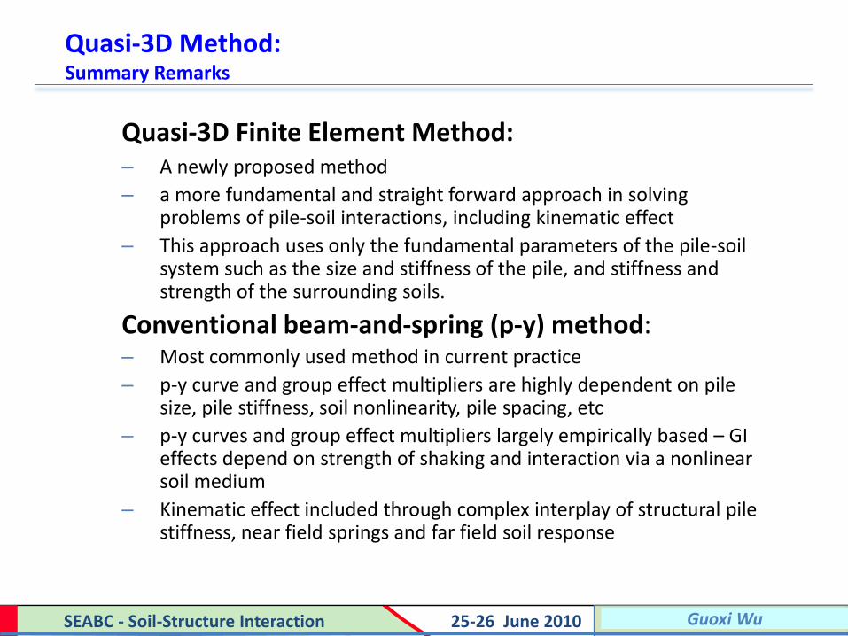
Quasi-3D Finite Element Method: – A newly proposed method
– a more fundamental and straight forward approach in solving problems of pile-soil interactions, including kinematic effect
– This approach uses only the fundamental parameters of the pile-soil system such as the size and stiffness of the pile, and stiffness and strength of the surrounding soils.
Conventional beam-and-spring (p-y) method: – Most commonly used method in current practice
– p-y curve and group effect multipliers are highly dependent on pile size, pile stiffness, soil nonlinearity, pile spacing, etc
– p-y curves and group effect multipliers largely empirically based – GI effects depend on strength of shaking and interaction via a nonlinear soil medium
– Kinematic effect included through complex interplay of structural pile stiffness, near field springs and far field soil response
Quasi-3D Method: Summary Remarks


![PROGRAM - iabse 2017 COLUMBIA (SEABC) IABSE ... 1_mb1-tl ;; m]f obmvl ;l0;uv71 ott;-] ;v- m7= ub;m7v7 7 ubm]- = ; b m|;mv;7 - vo =t ; ... ScientiÞc Program](https://img.pdfslide.us/doc/110x75/5abbd3807f8b9a441d8d4177/program-iabse-2017-columbia-seabc-iabse-1mb1-tl-mf-obmvl-l0uv71-ott-.jpg)