Embed Size (px)
Citation preview

Description of accessoriesfor the following cooling towers:
Cooling tower for open circuit operation DTSidestream cooling tower SK
Evaporative coolerfor closed circuit operation VK
Evaporative condenser VV
Air-cooled water cooler LW
Air-cooled condenser LV
Hybrid water-cooler HK
Accessories
E. W. Gohl GmbH | Pfaffenhäule 28 | D-78224 Singen | Tel. +49 (0)7731 .8806 -0 | Fax +49 (0)7731 .8806 -99 | [email protected] | www.gohl.de
Permanently Good Cooling
50
0/1
00
9
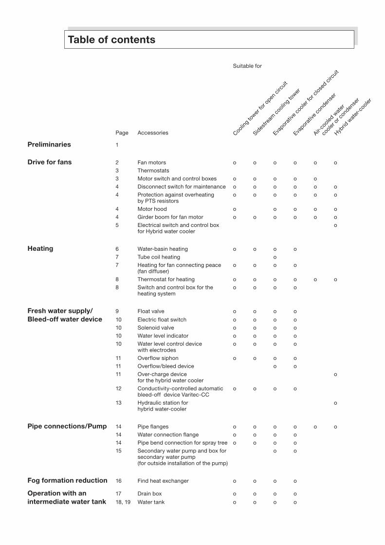
Table of contents
Suitable for
Page Accessories
Preliminaries 1
Drive for fans 2 Fan motors o o o o o o
3 Thermostats
3 Motor switch and control boxes o o o o o
4 Disconnect switch for maintenance o o o o o o
4 Protection against overheating o o o o o o by PTS resistors
4 Motor hood o o o o o
4 Girder boom for fan motor o o o o o o
5 Electrical switch and control box o for Hybrid water cooler
Heating 6 Water-basin heating o o o o
7 Tube coil heating o
7 Heating for fan connecting peace o o o o (fan diffuser)
8 Thermostat for heating o o o o o o
8 Switch and control box for the o o o o heating system
Fresh water supply/ 9 Float valve o o o o
Bleed-off water device 10 Electric float switch o o o o
10 Solenoid valve o o o o
10 Water level indicator o o o o
10 Water level control device o o o o with electrodes
11 Overflow siphon o o o o
11 Overflow/bleed device o o
11 Over-charge device o for the hybrid water cooler
12 Conductivity-controlled automatic o o o o bleed-off device Varitec-CC
13 Hydraulic station for o hybrid water-cooler
Pipe connections/Pump 14 Pipe flanges o o o o o o
14 Water connection flange o o o o
14 Pipe bend connection for spray tree o o o o
15 Secondary water pump and box for o o secondary water pump (for outside installation of the pump)
Fog formation reduction 16 Find heat exchanger o o o o Operation with an 17 Drain box o o o o
intermediate water tank 18, 19 Water tank o o o o
Coolin
g to
wer fo
r open
circ
uit
Sides
tream
coo
ling
tower
Evapora
tive c
ooler
for c
lose
d circ
uit
Evapor
ative
con
dense
r
Air-co
oled w
ater
coole
r or c
onden
ser
Hybrid
wat
er-c
ooler

Suitable for
Page Accessories
Sound dissipation / 20, 21 Fan enclosure o o o o o o
Means to direct 22 – 25 Silencer o o o o o o
the air flow 26 Air deflector plate o o o o o
26 Duct connecting piece o o o o o for air intake at the top
Maintenance duct 27 Maintenance ducts o o o o o o
28 Exhaust air hood o o o o o
28 Exhaust air deflector hood o o o o o
29 Exhaust air nozzle o o o o o
30 Flexible duct connection o o o o o o
31 Exhaust air damper o o o o o
32 Inlet air damper o o o o o o
33 Bird protective grid o o o o o o
33 Air filter mats o o o o o o
Anti-vibration (absorbing) 33 Anti-vibration rails o o o o o o
elements against 33 Neoprene rubber strips o o o o o o
mechanical vibration 34 Wide flange I-beams o o o o o o
and fastening devices 34 Base frames
34 Clamping claws o o o o o o
Double elastic support 35 Reverse flange o o o o o o
36 Thermal insulation/sound protection o o o o o o
Inspection devices 37 Inspection hatch for spray system o o o o o
37 Inspection hatch o for hybrid water cooler
37 Inspection hatch for water-basin o o o o o o
37 Inspection hatch o o o o o o
37 Hinges and swing handles o o o o o o
38 Inspection glass lamp o o o o o
Special requirements 38 Fan impellers plastic coated o o o o o o
Fluid bed powder coating 39 Fluid bed powder coating o o o o o o
Coolin
g to
wer fo
r open
circ
uit
Sides
tream
coo
ling
tower
Evapora
tive c
ooler
for c
lose
d circ
uit
Evapor
ative
con
dense
r
Air-co
oled w
ater
coole
r or c
onden
ser
Hybrid
wat
er-c
ooler
Coolin
g to
wer fo
r open
circ
uit
Sides
tream
coo
ling
tower
Evapora
tive c
ooler
for c
lose
d circ
uit
Evapor
ative
con
dense
r
Air-co
oled w
ater
coole
r or c
onden
ser
Hybrid
wat
er-c
ooler
Z6e

1
Preliminaries
Standard equipment of the main units, i.e. the components of the units, not their accessories
a) D-Line Cooling tower, sidestream cooling tower, evaporative cooler for closed circuit operation and evaporative condenser: bleed-off device, suspension arrangement for fully assembled units, inspection door, strainer for pump connection, flanged water connection (except for the fresh water connections and drains which have female pipe thread and the water connections for the primary water circuit for the evaporative cooler and condenser, which are without flanges).
b) Air-cooled water cooler, air-cooled condenser and hybrid water-cooler: Suspension arrangement for fully assembled units, inspection door, flanged water connections for water coolers, without flanges for condensers and drains with female pipe thread R 1 ¼“.
Units with two or more fan motors are not partitioned off with a separating wall (an exception are units with bipolar i.e. opposite fan arrangement). Therefore the motors must be switched simultaneously, however, with a time delay of max. 10 seconds.
Corrosion protection
a) The following accessories are plastic coated: drain box, exhaust air hood, exhaust air nozzle, bleed-off support panels, support of thermostats and switch boxes, duct connecting piece, silencer housing, switchbox holding device, inspection panels, overflow and bleed off device, fan enclosure, flanged water connection, water tank.
b) Coating of the surface: all galv. sheet metal parts are lightly sandblasted, heated in a furnace, and dipped into a plastic powder bed (Performance Polymer Alloy). The plastic coat is approx. 0,3 mm thick on each side. It has a homogeneous surface, it is elastic, resistant to chemical attack, light- and weather-resistant.
Float valve resonances
Periodical opening and closing of the valve may occasionally lead to water hammer noise in the make-up water supply circuit and cause a considerable disturbance. The causes are varied, e.g. incorrect pipe routing of the make-up water or an unacceptable high water pressure. If the unit is supplied with anti-vibration rails, we protect against such a disturbance by equipping the make-up water connection with a rubber hose of approx. 500 mm in length which should be routed in an arc. If resonances occur in spite of it, a valve silencer may be installed.
Electric switch boxes
It is possible to equip the units with a combination of switch boxes to serve a variety of electric uses, e.g. a larger switch box for sev-eral motors or one for fan and pump motors and pan heating.
When switch boxes are ordered, consideration is given to the various accessories which are to be connected to it, e.g. a separate heating system, for the electric heating cable, for open-shut-dampers, control air dampers, for motor PTC-thermistor protection; for the water level control device with electrodes or for the electric float switch in all switch boxes.
Foundations for the units
The foundations for our units, including their enclosures and water tanks, should be made waterproof when set up outdoors. When erected indoors, this holds true for the foundations, as well as the floor whereby, for practical reasons, the floor should be made wa-terproof with a drain. Waterproofing can be achieved by adding a sealing compound to the concrete mixture, by applying a layer of waterproof paint or by covering it with sheet metal or plastic.
2
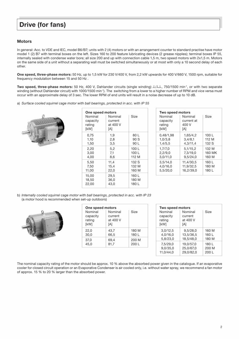
One speed motors Two speed motors Nominal Nominal Size Nominal Nominal Sizecapacity current capacity current atrating at 400 V rating 400 V[kW] [A] [kW] [A]
0,75 1,9 80 L 0,48/1,98 1,65/4,2 100 L 1,10 2,8 90 S 1,0/3,8 3,4/8,1 112 M 1,50 3,5 90 L 1,4/5,5 4,3/11,4 132 S
2,20 5,2 100 L 1,7/7,0 5,1/15,2 132 M 3,00 7,1 100 L 2,2/9,0 7,3/19,0 160 MK 4,00 8,6 112 M 3,0/11,0 9,5/24,0 160 M
5,50 11,4 132 S 3,5/14,0 11,4/30,5 160 L 7,50 15,4 132 M 4,0/16,0 11,9/32,5 180 M11,00 22,0 160 M 5,5/20,0 16,2/39,0 180 L
15,00 29,5 160 L 18,50 36,0 180 M 22,00 43,0 180 L
Drive (for fans)
Motors
In general: Acc. to VDE and IEC, model B6/B7; units with 2 (4) motors or with an arrangement counter to standard practise have motor model 1 (2) B7 with terminal boxes on the left. Sizes 160 to 200 feature lubricating devices (2 grease nipples); terminal boxes IP 55, internally sealed with condense water bore; all size 200 and up with connection cable 1,5 m, two speed motors with 2x1,5 m. Motors on the same side of a unit without a separating wall must be switched simultaneously or at most with only a 10 second delay of each other.
One speed, three-phase motors: 50 Hz, up to 1,5 kW for 230 V/400 V, from 2,2 kW upwards for 400 V/660 V, 1500 rpm, suitable for frequency modulation between 15 and 50 Hz .
Two speed, three-phase motors: 50 Hz, 400 V, Dahlander circuits (single winding) / , 750/1500 min-1, or with two separate winding (without Dahlander circuit) with 1000/1500 min-1). The switching from a lower to a higher number of RPM and vice versa must occur with an approximate delay of 3 sec. The lower RPM of end units will result in a noise decrease of up to 10 dB.
a) Surface cooled squirrel cage motor with ball bearings, protected in acc. with IP 55
One speed motorsNominal Nominal Sizecapacity currentrating at 400 V[kW] [A]
22,0 43,7 180 M30,0 66,5 180 L
37,0 69,4 200 M45,0 81,7 200 L
Two speed motors Nominal Nominal Sizecapacity currentrating at 400 V[kW] [A]
3,0/12,5 9,5/28,0 160 M 4,0/16,0 13,5/36,5 160 L 5,8/23,0 18,5/48,0 180 M
7,5/29,0 19,0/57,0 180 L 9,0/35,0 25,0/67,0 200 M11,0/44,0 29,0/82,0 200 L
b) Internally cooled squirrel cage motor with ball bearings, protected in acc. with IP 23 (a motor hood is recommended when set-up outdoors)
The nominal capacity rating of the motor should be approx. 10 % above the absorbed power given in the catalogue. If an evaporative cooler for closed circuit operation or an Evaporative Condenser is air cooled only, i.e. without water spray, we recommend a fan motor of approx. 15 % to 20 % larger than the absorbed power.

3
Thermostats
a) The thermostat has a 2 m long capillary and a cover for the sensing bulb. To regulate the on and off switching of the motor, there is an adjustable range which can be set from -5 °C to + 30 °C, switching capacity 10 A Ohm at 230 V, 50 Hz, protection acc. to IP 66. The mounting device consists of a piece of sheet metal for fastening, two metal angles with a plastic tube for guiding of the capillary, a screwed flange NW 15/R ½” with seal, screws and nuts.
b) Two stage thermostat with a capillary of 1,5 m length and a cover for the sensing bulb. For switching the motor individually there are the following components: two single-pole double- throw switches, temperature range -15 °C to + 35 °C, pre-set switching differential 2 K, adjust- able temperature differential between stages 2 to 6K, switching capacity 5,1 A Ohm at 230 V, 50 Hz, protected acc. to IP 55 (in a plastic casing). The mounting device consists of a piece of sheet metal, a transparent plastic casing, two metal angles with a plastic tube for guiding of the capillary, a screwed flange NW 15/R ½” with seal, screws and nuts.
c) Sensing element in four-wire-network to regulate the switching of the frequency-modulated fan-motors. Sensing element is installed into the sensing bulb ½” of brass (wickelized). The sensing devise will be delivered completely with housing and terminal. Protection according to IP 55. Ambient temperature + 100 °C. With cable 0,75-1,5 mm² for ranges till 50 m (NTC) or 100 m (PTC).
The thermostat is fastened on a side of the unit near the fan motor, while the sensing bulb is placed beneath the water level at the cooling tower DT; if a remote water tank is used, the sensing bulb is installed into the lower lying water tank. Units without a separating wall but with several motors should be operated with one thermostat; in the case of bi-polar units and those with a separating wall, we recommend the use of two thermostats.
Motor switch and control boxes
The switch and control box enables several functions: On and off switching via a thermostat, its control lights give immediate alert to disturbances, in the case of two-speed motors it affects a delay of the individual switching steps. Each switch and control box for outdoor use is set up for a supply voltage of 230/400 V, 50 Hz, and protected acc. to IP 65. The motor is always connected directly over the low RPM. In most cases the switch and control box is fastened next to or near the motor with a mounting device. Potential-free contacts for external signals are taken into consideration.
a) For motors with one speed feature following components are mounted and wired: 1 master switch which can be locked (according to VDI 0113), 3 fuses, 1 trip-line fuse, 1 contactor with bi-relay, 1 signal-light, 3 screwed cable connections. Size of switch box E 11 E 12 E 13 E 14
For motor nominal capacity rating [kW] 4,0 18,5 30,0 45,0
b) For motors with two speed feature following components are mounted and wired: 1 master switch which can be locked (according to VDI 0113), 3 or 6 fuses, 1 trip-line fuse, 3 contactors – 2 of them with bi-relays, 2 signal-lights, 3 time relays, 4 screwed cable connections.
Size of switch box D 31 D 32 D 33 D 34
For motor nominal capacity rating [kW] 1,7/7 4/16 7,5/29 11/44
If for reasons of shipment or structural accommodation the switch box is shipped separately, the wiring to the motor and thermostat can be done only at the building site. See “preliminaries” side 1 for more information on switch box combinations.

4
Protection against overheating by PTC resistors
a) The protection again overheating consists of 3 temperature sensors which are wrapped into the motor winding. The semiconductor resistors interrupt the electric current supply at a certain temperature via a release mechanism. This is of utmost importance to the prevention or damage of the electrical equipment which could, otherwise, occur by blockage of the rotors, failure of a phase, excessively high switching capacity, overheating and overloading. The sizes of the sensors depend on the motor sizes. At motor size 200 and up with connections cable of 1,5 m.
b) This release mechanism (control device) is suitable for all motors with thermistor protection. It shuts off the control voltage when the motor overheats. Its electronic locking mechanism prevents an automatic switching on after cooling of the motor; switching on is accomplished by activating of the back spacer. The built in relay switches itself off in times of voltage failure, yet switches itself on again when the voltage returns to normal.
Disconnect switch for maintenance
The isolator switch, which can be locked, is a main accessory to avoid accidents and facilitate maintenance work. Constructed acc. To VDE 0113, it is protected acc. to IP 55. It separates the capacity load (not only the control load) and allows a safe operation and manipulation of the implement. It is usually fastened with screws on a side of the unit, near the motor.
Motor-hood
It is made of galvanized, plastic coated sheet metal and serves especially as a protection against the corrosive influences of the weather. There are three sizes: for motors up to 3 kW, for motors over 3 kW to 15 kW, for motors over 15 kW. In case of repeat order, please state size of motor!
Girder boom for fan motor
It serves for assembly of fan motors and consists of a girder boom and a holding device which can be fixed at the left or right side of the cooling tower casing. The girder boom will be fixed into the holding device. It will be recommended for large fan motors.

5
Electrical switch and control box for Hybrid water-cooler
It consists of following components (for units with more fan motors in common):switch box with aeration heating facilities, terminal box, switch for maintenance, frequency transformer, control and software.
The control of the unit occurs with a SPS. For the input and the revision operation an “operator panel” is available. It consists of input key buttons and display. By changing the PID-control parameters the control system can be adapted to the essential cooling capac-ity. The control system operates in dependence of the water outlet temperature of the cooler. If the water outlet temperature will pass over the adjusted temperature, the PID-control system begins to operate.Each switch and control box is set up for a mains voltage of 230/400 V, 50 Hz, IP 65 according to VDE. The wiring between the fan motor and the frequency changer must be wired with screened cable. The cable length between the fan motor and the switch and control box should be not longer than maximum 15 to 20 m.
Electrical switch and control box for single unitsMains and motor voltage 400 V ( 3 ~) 50 Hz
Unit Fan motor Frequency Converter E-box size incl.size 1500 min-1, 400 V, base plate of 200 mm 50 Hz, IP55 Dimensions Weight Range of adjustment: H/B/D H/B/D 10-50 Hz kW kW mm kg mm
HK 33 5,5-7,5 4/5,5-5,5/7,5 430/135/205 7 2000/800/500HK 45 7,5 5,5/7,5 430/135/205 7 2000/800/500HK 52 11 7,5/11 430/135/205 7 2000/800/500HK 77 15 11/15 430/135/205 7 2000/800/500
HK 2/33 11-15 7,5/11-11/15 430/135/205 7 2000/800/500HK 2/45 15-18,5 11/15-15/18,5 430/135/205 und 7 + 21 2000/800/500 595/185/215HK 2/52 18,5-22 15/18,5-18,5/22 595/185/215 21 2000/800/500HK 2/77 30 22/30 595/185/215 21 2000/800/500
HK 3/45 18,5-22-30 15/18,5-18,5/22-22/30 595/185/215 21 2000/1200/500HK 3/52 30 22/30 595/185/215 21 2000/1200/500HK 3/77 37-45 30/37-37/45 700/220/290 38 2000/1200/500
HK 4/45 2 x (15-18,5) 2 x (11/15-15/18,5) 2 x (430/135/205- 7-21 2000/1600/500 595/185/215)HK 4/52 2 x (18,5-22) 2 x (15/18,5-18,5/22) 2 x 595/185/215 2 x 21 2000/1600/500HK 4/77 2 x 30 2 x 22/30 2 x 595/185/215 2 x 21 2000/1600/500
HK 5/45 (15-18,5)+(18,5-22-30) (11/15-15/18,5)+ 2 x (430/135/205- 7-21 2000/1600/500 (15/18,5-22/30) 595/185/215)HK 5/52 (18,5-22)+30 (15/18,5-18,5/22)+22/30 2 x (595/185/215) 2 x 21 2000/1600/500HK 5/77 30+(37-45) 22/30+(30/37-37/45) 2 x (595/185/215- 21-38 2000/1600/500 700/220/290)
HK 6/45 2 x (18,5-22-30) 2 x (15/18,5-18,5/22- 2 x 595/185/215 2 x 21 2000/1600/500 22/30)HK 6/52 2 x 30 2 x 22/30 2 x 595/185/215 2 x 21 2000/1600/500HK 6/77 2 x (37-45) 2 x (30/37-37/45) 2 x 700/220/290 2 x 38 2000/1600/500

6
Water-basin heating
a) The immersion heaters are heating cartridges (230 V, 50 Hz), protected in acc. with IP 65 with ground, a pipe sleeve of V2A-steel, the main body and counter screw nut are made of brass contact, and the cover is of aluminium with V2A-screws. The heating car- tridges, installed from the outside and below the water level, insure trouble-free winter operation for up to –20 °C outside tempera- tures (when the pipes are well insulated or outfitted with electric. heating cable).
Heating
D-Line cooling tower/ Evaporative cooler for closed Heating Heating CurrentSidestream cooling tower circuit operation and cartridges perform- consump- evaporative condenser quantity ance tion [kW] per [A] per 6 8 8/5 8/6 8/7 1 0,5 2,210 12 13 16 18 21 23 25 12/5 12/6 12/7 16/5 16/6 16/7 1 1,0 4,4
20 26 26/5 26/6 26/7 1 1,5 6,528 33 36 39 37 42 45 50 33/5 33/6 33/7 45/5 45/6 45/7 1 2,0 8,7
46 52 58 63 57 64 70 77 82 52/5 52/6 52/7 77/5 77/6 77/7 2 1,5 2/28 2/33 2/36 2/39 2/37 2/42 2/33/5 2/33/6 2/33/7 2 2,0 6,52/45 2/50 2/45/5 2/45/6 2/45/7 2 2,0 8,7
2/46 2/52 2/58 2/63 2/52/5 2/52/6 2/52/7 3 2,0 8,72/57 2/64 2/70 2/77 2/82 2/77/5 2/77/6 2/77/7 4 1,5 6,5
3/37 3/42 3/45 3/50 3/45/5 3/45/6 3/45/7 3 2,0 8,73/46 3/52 3/58 3/63 3/52/5 3/52/6 3/52/7 4 2,0 8,73/57 3/64 3/70 3/77 3/82 3/77/5 3/77/6 3/77/7 6 1,5 6,5
4/42 4/45 4/50 5 1,5 6,54/52 4/58 4/63 5 2,0 8,74/57 4/64 4/70 4/77 4/82 4/77/5 4/77/6 4/77/7 6 2,0 8,7
5/45 5/50 6 1,5 6,55/52 5/58 5/63 6 2,0 8,75/57 5/64 5/70 5/77 5/82 5/77/5 5/77/6 5/77/7 7 2,0 8,7
6/45 6/50 6 1,5 6,56/52 6/58 6/63 9 1,5 6,56/57 6/64 6/70 6/77 6/82 6/77/5 6/77/6 6/77/7 9 2,0 8,7
D-Line cooling tower bipolar 8/57 8/64 8/70 8/77 8/82 12 2,0 8,710/57 10/64 10/70 10/77 10/82 14 2,0 8,712/57 12/64 12/70 12/77 12/82 18 2,0 8,7
b) Immersion heater thermostat with thermal cut-out for protection against overheating; heating capacity 2 kW (230 V, 50 Hz), maximum switching capacity 9,2 A, protected in acc. with IP 65, ground contact, a pipe sleeve of V2A-steel, housing of cast-aluminium, screws of V2A-steel, main body and counter screw nut of brass. If there is no safety electrode or float switch to guard against overheating of the cartridges, then one cartridges per unit should be replaced by one with a thermal cut-out. The electrical circuit will be interrupted before the cartridges become overheated by water shortage, because the cartridge with thermal cut-out, its sensing bulb face side up and installed 25 mm higher than the others, can be interlocked with all cartridges. We recommend the use of two thermostats, and if necessary, two cartridges with thermal cut-outs for bipolar units.
c) Immersion heater thermostat with thermal cut-out for protection against overheating in acc. with SEV with one cable run for each load and control part. Further description see b).

7
Tub coil heating
The tub coil heating for the water-basin will be used to insure trouble-free winter operation by air-cooled operation of the evaporative cooler without water spray. The secondary water circuit can be kept free of frost when the wet cooler operates air-cooled without water spray at outside temperatures below 0 °C. It should be used additional to the standstill heating of the water-basin. The tub coil heating is connected to the primary circuit. This part of the heat to be discharged is used to prevent the for-mation of ice in the water-basin. For the fresh water supply should be used an electric. float switch with a solenoid valve instead of a float valve. The coil is made of steel tub ¾” of approx. 2,65 mm wall-thickness and is fully hot-dip galvanised after manufacture. The coil is connected to the primary circuit, it is drainable. The units with more than one fan has for each fan (single cell) one tub coil heating. The units 8/5, 8/6, 8/7 and 12/5, 12/6, 12/7 can’t be supplied with a tub coil heating.
Heating for fan connection piece (fan diffuser)
The heating for fan connection pieces (fan diffuser heating) will be used to keep the air inlet area free of ice by wet-cooled winter operation. The unit has additional a drain groove into the cooler above the diffuser. The diffuser heating consists of self-adhesive silicon-heating mats which are covered on the outer side with an aluminium panel and fix at the fan diffuser housing, distribution box protecting tube for cable and thermostat. The quantity of mats, distribution boxes, protecting tubes, thermostats, screw connections and fixing devices depends on the unit size.

8
Thermostats
a) Thermostat with bulb rod for installation in the water pan. Non adjustable switching differential 2 K, switching capacity 10 A Ohm at 230 V, 50 Hz, protected acc. IP 55 and control box.
If you operate a bi-polar unit with a partitioning wall, we recommend the use of 2 thermostats, one for each pan compartment. Of those two thermostats which are connected to the same switch and control box, the one sensing the lowest temperature indicate the switching on and off of the immersion heaters. Installation of only one switch and control box suffices when this type of switching arrangement is used.
In cases where each heater has its own thermostat, all 2 thermostats may be connected to any of the larger switch and control boxes. The usual set-up values for the thermostat range from +6 °C (in) to +9 °C (out). b) Defrosting thermostat. Thermostat with sensing bulb, sensor and a 2 m long capillary will be used to control the temperature of the liquid. With change-over contacts. Adjustment range: -5 to + 30 °C. Difference between “on” and “off” adjustable from switch point by non-freezing: adjust +4,5 °C at scale, then it switches off at +6,5 °C.
Switch and control box for the water-basin heating
The switch and control box is fastened to the unit near the fan drive. The following compo-nents are part of its mechanism: fault current switch guard, contactor, fuses and termi-nals, control lights, connections for the wrap-around heating cable, and potential-free contacts for external signals. If the switch and control box is shipped separately, wiring to the immersion heaters and thermostat has to be done by the customer at building site.
Size of switch and control box, size 1 2 3 4
Capacity load, kW 3 9 18 36
For more information about switch and control box combinations, please check preliminaries, side 1.

9
With the use of a float valve, the float action is carried over mechanically onto the closing mechanism of the valve body (float, rods and valve are one apparatus), but when the make-up water supply is regulated with a solenoid valve, a second equipment, namely an electric float switch, becomes necessary. Depending on the water level, the electric float switches the current, necessary for opening and closing of the solenoid valve, on and off.
Float valve
Holding the brass float body by its sturdy screw neck, it is screwed from the inside of the water pan onto the fresh water connection flange, so that the run-out shows downwards (this mounting is acc. to DIN 1988). Correct setting is achieved by moving the rod (gear) and the copper float. When the operating water level is reached, the float must close. The pre-pressure should not climb over 2 bar. Please take note to secure all fresh water connections (especially plastic piping) very firmly (see preliminaries, side 1).
a) 1 float valve per unit
Fresh water supply/Bleed-off water
D-Line cooling tower bipolar
8/57 8/64 8/70 8/77 8/82 R 1 1/2“10/57 10/64 10/70 10/77 10/82
12/57 17/64 12/70 12/77 12/82 R 2“
In this case, selection of size goes acc. to the total cooling capacity
Cooling capacity up to kW 700 1400 2800 5600
Valve-size R 1“ R 1 1/4“ R 1 1/2“ R 2“
b) 2 float valve per unit
c) 1 float valve for several units connected on the water side
D-Line cooling tower Evaporative cooler for closed circuit operation, Valve-sizeSidestream cooling tower evaporative condenser
6 8 10 12 13 16 8/5 8/6 8/7 12/5 12/6 12/7 16/5 16/6 16/7 R 1/2“
18 21 23 25 20 26 28 26/5 26/6 26/7 R 3/4“33 36 39 37 42 45 50 46 33/5 33/6 33/7 45/5 45/6 45/7 52/5 52/652 58 63 57 64 70 77 82 52/7 77/5 77/6 77/7
2/28 2/33 2/36 2/39 2/37 2/42 2/33/5 2/33/6 2/33/7 2/45/5 2/45/6 2/45/7 R 1“2/45 2/50 2/46 2/52 2/58 2/63 2/52/5 2/52/6 2/52/7
2/57 2/64 2/70 2/77 2/82 3/37 2/77/5 2/77/6 2/77/7 3/45/5 R 1 1/4“3/42 3/45 3/50 3/46 3/52 3/58 3/45/6 3/45/7 3/52/5 3/52/6 3/52/73/63 3/57 3/64 3/70 3/77 3/82 3/77/5 3/77/6 3/77/7
4/42 4/45 4/50 4/52 4/58 4/63 4/57 4/77/5 4/77/6 4/77/7 R 1 1/2“4/64 4/70 4/77 4/82 5/45 5/50 5/52 5/77/5 5/77/6 5/77/75/58 5/63 5/57 5/64 5/70 5/77 5/82
6/45 6/50 6/52 6/58 6/63 6/57 6/77/5 6/77/6 6/77/7 R 2“6/64 6/70 6/77 6/82

10
Electric float switch (for electric. water level regulation or to signal dry operation)
The magnetically operating electric float switch is operated magnetically and installed in eitherthe unit or in the water tank above the water level. Those parts which become wet are made ofV4A-steel, while the switch box is constructed of an aluminium alloy. The switching differentialis adjustable. Protected in acc. with IP 65.
Water level control device with electrodes
It is for controlling the water levels and to signal dry operation for conductive mediums.It indicates following status:
The cable between the water level control device and the switching amplifier (fixed into the switch box) should not be longer than max. 50 m. It has to be wired with screened cable. More technical specifications see incl. A31 (5-poles) / A31a (6-poles).
Solenoid valve
The solenoid valve is a direct controlled two-way valve with a brass body. It operates electro-magnetically by servo control, has a terminal box and two female pipe threads. Not activated it is in a closed position, protected in acc. to IP 65, set up for water, 0 to 10 bar pre-pressure, 0 °C to 90 °C water temperature, 230 V, 50 Hz. For choosing the right valve size (nominal size R ½” to R2”), please refer to the table for float valve on page 9. The solenoid valve should not be used for contaminated water.
Water level indicator
It serves to control the operation water level.
with 5 contacts
· signals dry operation· signals cancelling of dry operation· open fresh water supply· shuts of fresh water supply· reference contact
with 6 contacts
· signals dry operation· signals cancelling of dry operation· open fresh water supply· shuts of fresh water supply· overflow contact· reference contact

11
Overflow-siphon (with adjustable cover)
The trap is made of plastic coated galvanized sheet metal and screwed to the overflow opening. It will be used when bleed-off is not performed with a automatic bleed-off device depending on capacity. The overflow-siphon with adjustable cover is for mechanical bleed-off device. Its siphon-like construction keeps air from entering the overflow and, thereby, prevents water from being carried out. It will be used only for cooling towers for open circuit DT and side discharge cooling towers SK.
Overflow/bleed-off device
Its made of galvanized sheet metal plastic coated and screwed to the overflow opening. When bleed-off is not performed with the bleed-off device depending on capacity or with another mechanism, the overflow device must be used. It is provided with a adjustable cover and situ-ated in the spray area, discharges the required quantity of bleed water directly through the over-flow. It will be used only for evaporative cooler VK and evaporative condenser VV.
Overflow-siphon (closed)
Its made of plastic coated galvanized sheet metal and screwed to the overflow opening. It will be used when bleed-off will be done by a automatic bleed-off device depending in capacity. It keeps air from being carried out. It will be used only for cooling towers DT, Side discharge cool-ing towers SK, evaporative cooler VK and evaporative condenser VV.
Fill level indicator (over-charge device) for the hybrid water-cooler
Filling switch with an insensitive stainless metal casing. It has following specification:
· Connection 1“· LED information about switch and unit states· Change of polarity-and short cut protection · Industrial plug connection
More technical information see A52

12
Conductivity-controlled automatic bleed-off device Varitec - CC
The conductivity-controlled bleed-off device will be used for the automatic control of the max. salt-concentration in the circulating water of the cooling tower.
The main components:A conductivity measuring cell, a electronic controller and a bleed-off ball valve. Description and technical data see enclosure A.
The bleed-off water automatic controls the maximum salt concentration in the water circuit of the cooling tower. During plant operation water is continuously evaporating, thus the salt concentration in the remaining circulating water increasing. Therefore the part of the circulating water has to be replaced by fresh water when the salt con-centration exceeds a certain limit value. The electric conductivity of the circulating water is proportional to its salt concentration. Therefore it can be used as the control-led variable for the bleed-off water.
The conductivity is determined by a measuring cell and serves as an input signal for the regulator. In addition the measured value will be shown on a display of the regu-lator. When the set desired value is exceeded, the regulator opens the electrically driven ball-type cock and part of the circulating water can flow off. The discharged water volume is replaced by fresh water (via a float valve or a float switch in combina-tion with a solenoid valve). The ball-type cock will be closed by the regulator when the desired value for the salt concentration is about 3 % less.
Construction
· Pre-assembled, ready for connection system· Size ½“ (DN15) for a bleed-off consumption < 1,6 m³/h, or 1“ (DN 25) for a bleed-off water rate >1,6 m³/h· Conductive measuring cell with heat detector, cell constant 1.0, graphite electrode· No tools necessary for assembly the measuring cell, electrodes are easily accessible· Calibration without operation (dry-calibration)· Calibration and control point adjustment with a tumbler switch and potentiometer· Touch switch for basic adjustment fixed into the terminal board (by set into operation adjustment of control point is only necessary)· Interference relay at the rest current position adjustable. Signals interferences also by cutting out of the circuit· Automatic temperature compensation· LCD Display, indicates all operating conditions by LED´s
Structural components
· Conducting-Controller LFRG-CC· Measuring cell LFK 1,0 E· Bleed-off about ball valve MKV 15 or MKV 25· Connection cable with plug for measuring cell
Accessories
· For winter-operation below 0°C: An atmospheric protective housing with heating is needed.

13
Hydraulic station for hybrid water-cooler
The hydraulic station will be supplied readily for connection with all safety armatures, cleaning tank with dosing pump and empty code indicator. The hydraulic compo-nents are completely tubed in a metal cupboard. The pipe-work between mixing sta-tion and hybrid water cooler as well the fresh water and the warm water supply has to be done by customer. The construction and types for metal cupboard, dosing pump, cleaning tank, armatures etc. are according to our specifications. The hydraulic sta-tion has to be installed in a heated room.
Mixing station for single units Mixing station for several units
Unit- Cabinet- Hydraulic- Rate of flow Number Cabinet- Hydraulic- Rate of flowsize size station of units size station size sizeHK H/W/D Cleansing Spray system H/W/D Cleansing Spray system mm equip. 3,5 bar 1,1-2 bar mm equip. 3,5 bar 1,1-2 bar m3/h m3/h m3/h m3/h
33 2000/800/600 R 1“ 2-4 2000/1200/600 R 1“45 “ “ “ “52 “ “ “ “77 “ “ “ “
2/33 2000/800/600 R 1“ 2-4 2000/1200/600 R 1“2/45 “ “ “ “ “2/52 “ “ “ “ “2/77 “ R 1 1/2“ “ “ R 1 1/2“
3/45 2000/1200/600 R 1 1/2“ 2-4 2000/1200/600 R 1 1/2“3/52 “ “ “ “ “3/77 “ “ “ “ “
4/45 2000/1200/600 R 1 1/2“ 2-4 2000/1200/600 R 1 1/2“4/52 “ “ “ “ “4/77 “ “ “ “ “
5/45 2000/1200/600 R 1 1/2“ 2-4 2000/1200/600 R 1 1/2“5/52 “ “ “ “ “5/77 “ R 2“ 2-3 “ R 2“
6/45 2000/1200/600 R 2“ 2-3 2000/1200/600 R 2“6/52 “ “ “ “ “6/77 “ “ “ “ “
in acc. with theconstruction/design
in acc. with theconstruction/design

14
Pipe connections/pump
Pipe flanges with bolts and gaskets
Welding neck flange, with bolts and sealing materials, suitable as a counter flange e.g., for the spray tree, water outlet, overflow, drain, by-pass and connecting lines.
PN 16, DIN 2633: size DN 50 to DN 150PN 10, DIN 2632: size DN 200 to DN 300
Thread flanges
a) thread flange, galvanized steel b) thread flange, polyamide PN 6, DIN 2565: R 3/4” up to R 2” PN 6, DIN 2565: R 1/2”
Water connecting flanges with bolts and sealing materials
This water connecting flange consists of a steel plate, a pipe and a flange; it is welded and plastic coated. Its use is chiefly for by-pass and additional water connections. PN 16, DIN 2633, Sizes DN 50 to DN 150PN 10, DIN 2632, Sizes DN 200 to DN 300
Pipe bend connections for spray tree
This elbow connection facilitates the connecting of the water line to the spray system, especially in the case of bi-polar cooling towers with fan enclosure which often require 2 to 3 spray tree connections it makes it possible to get by with one flange connection only. Besides, the pipe lines from the building site do not need to be taken through the fan enclosures.The elbow connection consists of a steel pipe and flanges PN 16 / PN 10. It is galvanized after manufacture. Gaskets, bolts and nuts are provided fastening it to the unit.
a) Water feeding from above Size A1: Elbow and flange DN 80 or DN 100, acc. to the nom. width of the spray tree connection
A2: 2 branches DN 100, feeding DN 125 or DN 150, depending on the water flow rate
A3: 3 branches DN 100, feeding DN 150 or DN 200, depending on the water flow rate
b) Water feeding from the side which is turned away from the fan motor Size B1: Elbow and flange DN 80 or DN 100, depending on the nom. width of the spray tree connection
B2: 2 branches DN 100, feeding DN 125 or DN 150, depending on the water flow rate
B3: 3 branches DN 100, feeding DN 150 or DN 200, depending on the water flow rate
Other styles, e.g. up to 6 branches or as a collector for the suction line are possible. The feeding lines coming from the building site (have to be supported).

15
Secondary water pump for spraying
Secondary pump with motor, 1400 min-1, protected in acc. with IP 55, 50 Hz, for 400 V.
These pumps are selected for installation into the water-basin.
(Switch and control box see preliminaries side 1. Further more, we recommend the electric float switch for the pump, as a safety switch to prevent the pump for run dry without water).
The piping for the secondary water circuit consists of a pressure- and corrosion-resting flexible spiral tube, which connects spray tree and secondary pump fastened with hose clamps.
Box for secondary water pump (fixed outside)
To improve the maintenance work at the secondary pump, the pump box is fixed outside the cooling tower housing.
Evaporative cooler Pumpsize Pumpmotor Nom. currentfor closed circuit, at 400 VEvaporative condenser [kW] [A]
8/5 8/6 8/712/5 12/6 12/7 32-160/160 0,75 1,9
16/5 16/6 16/726/5 26/6 26/7 40-160/160 1,1 2,8
33/5 33/6 33/745/5 45/6 45/752/5 52/6 52/7 80-160/170 2,2 5,577/5 77/6 77/7
2/33/5 2/33/6 2/33/72/45/5 2/45/6 2/45/72/52/5 2/52/6 2/52/7 80-160/180 3,0 7,12/77/5 2/77/6 2/77/7
3/45/5 3/45/6 3/45/73/52/5 3/52/6 3/52/7 80-160/170 + 2,2 + 5,5 +3/77/5 3/77/6 3/77/7 80-160/180 3,0 7,1
4/77/5 4/77/6 4/77/7 2 x 80-160/180 2 x 3,0 2 x 7,1
5/77/5 5/77/6 5/77/7 1 x 80-160/170 1 x 2,2 1 x 5,5 2 x 80-160/180 2 x 3,0 2 x 7,1
6/77/5 6/77/6 6/77/7 3 x 80-160/180 3 x 3,0 3 x 7,1
CoolingTower
16
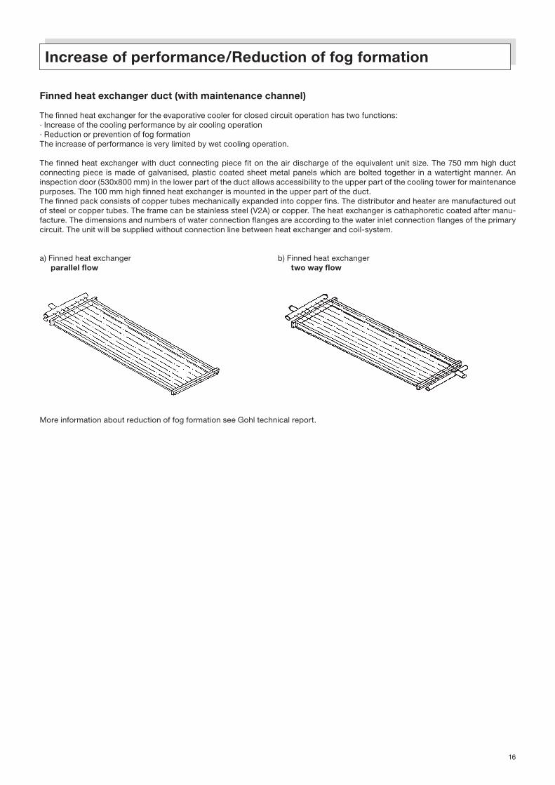
Finned heat exchanger duct (with maintenance channel)
The finned heat exchanger for the evaporative cooler for closed circuit operation has two functions:· Increase of the cooling performance by air cooling operation· Reduction or prevention of fog formationThe increase of performance is very limited by wet cooling operation.
The finned heat exchanger with duct connecting piece fit on the air discharge of the equivalent unit size. The 750 mm high duct connecting piece is made of galvanised, plastic coated sheet metal panels which are bolted together in a watertight manner. An inspection door (530x800 mm) in the lower part of the duct allows accessibility to the upper part of the cooling tower for maintenance purposes. The 100 mm high finned heat exchanger is mounted in the upper part of the duct.The finned pack consists of copper tubes mechanically expanded into copper fins. The distributor and heater are manufactured out of steel or copper tubes. The frame can be stainless steel (V2A) or copper. The heat exchanger is cathaphoretic coated after manu-facture. The dimensions and numbers of water connection flanges are according to the water inlet connection flanges of the primary circuit. The unit will be supplied without connection line between heat exchanger and coil-system.
a) Finned heat exchanger b) Finned heat exchanger parallel flow two way flow
More information about reduction of fog formation see Gohl technical report.
Increase of performance/Reduction of fog formation

17
Operation with an intermediate water tank
Drain-box
If a relative large volume of water is to run freely, in a certain amount of time, from the unit´s water basin into a lower lying water tank, it is necessary to use, for equal static-pressure building-up, either a pipe with a large diameter or several pipes with smaller diameters. Through the use of a drain box, the amount of water in the unit´s basin -depending on the type of unit- can be lowered up to 85%, i.e. the operating weight can be decreased appreciably and, furthermore, a smaller remote water tank will suffice. Please, also note the following: the water outlet connection piece can be fastened either on the side or on the bottom of the drain box. Such an implement is best placed upon longitudinally or diagonally running foundation strips of a min. height of 350 mm and a max. width of 200 mm (see dt 25e, di 13e). For units with several fans you may wish to install several drain boxes. The diagrams below indicate the most suitable pipe diameters.
Units with a free-flowing drain system, i.e. those which operate with a remote water tank, do not require fresh water-drain-, and stand-ard pump connections. To prevent an uncontrollable enlargement of the discharge resistance, a strainer is also not necessary. The strainer belongs, in such a case, to the remote water tank.

18
Water tank (installed in a heated room)
The water tank is made of galvanized, plastic coated sheet metal panels, which are bolted together and well sealed, with a long lasting sealing compound. The tank has to be set firmly on a smooth foundation. To determine its size, the amount of circulating water, length and diameter of its pipes (above the tank`s overflow), as well as the amount of water in the pan/or drain box are to be considered carefully (see technical report 03). The connecting flanges are of type PN16. The overflow pipe in the tank is pulled up in order to achieve higher overflow rates. Since the inlet openings are to be cut into the tank covers to fit the diameter of the connecting pipes, it must be done at the building site. Care must be taken to cut the circular pipe openings as 2 matching halves into both parts of the covers edges.
a) Standard - intermediate water tank (for one consumer) Its cover is divided in the centre. It can, therefore, be opened for cleaning purposes-particularly for cleaning of the water outlet strainer and for adjusting for the float valve, without disturbing the pipes.
Size of tank * 1A 2A 3A 4A 5A 6A Empty weight kg 170 200 300 370 470 670 Water up to level K, kg 350 530 725 1100 1650 2500 Receptivity from level K, 130 200 380 600 900 1300to level J, kg Length A 1170 1750 2000 2000 2340 3513
Width B 686 686 686 1006 1256 1256
Height C 920 920 1170 1170 1170 1170
D 800 1000 1400 1400 1800 1754
E 493 493 493 853 1078 1078
Dimensions, mm F 343 343 343 503 628 628
G 168 168 168 203 203 203
H 68 68 68 75 75 75
I 850 850 1100 1100 1100 1100
J 780 780 1000 1000 1000 1000
K 570 570 670 670 670 670
N 65 80 100 125 150 200
Nom. width, mm O 15 15 20 25 32 40
P 65 65 65 80 80 80
Q 65 65 65 80 80 80
* the exact selection has to be done in accordance with the customer sided circumstances.

19
b) Intermediate water tank with compartments for cold and warm water (for several consumers) In contrast to the standard intermediate water tank, this water tank is outfitted with a three-sectional cover. The tank itself is divided into 2 compartments by 2 partitioning panels which have a hollow space between them for the purpose of insulation. There is, accordingly, also a second pump connection installed. The tank´s purpose is to provide a constant amount of circulating water for the cooling tower when the cooling water from the heat exchanger (e.g. condenser, generator) drains of freely, or if great differing amounts of water would result because of the on and off switching of individual parallel placed heat exchangers.
Size of tank * 2B 3B 4B 5B 6B Empty weight kg 220 320 400 510 740 Water up to level K, kg 530 725 1100 1650 2500 Receptivity from level K to level J, kg 200 380 600 900 1300 Lenght A 1750 2000 2000 2340 3513
Width B 686 686 1006 1256 1256
Height C 920 1170 1170 1170 1170
D 710 835 835 955 1370
E 493 493 153 178 178
Dimensions, mm F 203 203 503 628 628
G 493 493 803 1053 1053
H 68 68 75 75 75
I 850 1100 1100 1100 1100
J 780 1000 1000 1000 1000
K 570 670 670 670 670
L 343 343 503 628 628
M 400 400 140 140 140
N 80 100 125 150 200
Nom. width, mm O 15 20 25 32 40
P 65 65 80 80 80
Q 65 65 80 80 80
* the exact selection has to be done in accordance with the customer sided circumstances.

20
Fan Enclosure
The fan enclosure is made of galvanized, plastic coated sheet metal panels which are fastened together with stainless steel bolts and fastened onto the main unit where it encloses the fan (fans) in such a way that air can only enter on one side. The enclosure is neces-sary part for the installation of intake silencers.A removable bird protective grid (see pg. 33) can be installed on the open side. If more air inlet ducts or inlet silencers are needed, a bird protective grid is unsuitable. The foundation or supports must be enlarged to suit the added enclosure. An inspection panel is installed on the side of the unit with a belt drive. Cut-outs for accommodation of piping above the fans are usually carried out on the building site if exact plans for their location were not provided when the order was placed. We are able to supply assembled and installed enclosures up to a width of 3602 mm. Noises in front of and next to the fan are muffled considerably approx. 3 dB by the fan enclosure. The resulting pressure loss is only approx. 15 Pa.Ensure that the inspection panel will only be opened if the fan is turned off because of danger of injuries by rotary parts of the fan drive.
a) Standard Fan Enclosure (air intake from the rear)
Silencers and means to direct the flow of air
* Enclosures 2000 mm high have an inspection panel of a 930/1760 mm (width/height) in the interior
Cooling towerfor open circuitSidestream cooling towerEvaporative coolerfor closed circuitEvaporative condenser Dimensions, mm WeightAir-cooled water coolerHybrid water-cooler L B H L with kg,(regardless of end number) unit approx.
6 8 630 680 1750 1550 6010 12 800 880 1750 1970 9013 16 800 880 1750 2640 90
18 21 23 25 920 1250 1750 2090 10020 26 920 880 1750 3680 95
28 33 36 39 1650 1250 1750 3490 15537 42 45 50 1650 1250 1750 3990 155
46 52 58 63 1650 1250 1750 4410 15557 64 70 77 82 1980 1250 2000 5490 225
2/28 2/33 2/36 2/39 1650 2420 1750 3490 2252/37 2/42 2/45 2/50 1650 2420 1750 3990 225
2/46 2/52 2/58 2/63 1650 2420 1750 4410 2252/57 2/64 2/70 2/77 2/82 1980 2420 2000 5490 325
3/37 3/42 3/45 3/50 1650 3590 1750 3990 2953/46 3/52 3/58 3/63 1650 3590 1750 4410 2953/57 3/64 3/70 3/77 3/82 1980 3590 2000 5490 425
4/42 4/45 4/50 1650 4760 1750 3990 3654/52 4/58 4/63 1650 4760 1750 4410 3654/57 4/64 4/70 4/77 4/82 1980 4760 2000 5490 525
5/45 5/50 1650 5930 1750 3990 4355/52 5/58 5/63 1650 5930 1750 4410 4355/57 5/64 5/70 5/77 5/82 1980 5930 2000 5490 625
6/45 6/50 1650 7100 1750 3990 4356/52 6/58 6/63 1650 7100 1750 4410 5056/57 6/64 6/70 6/77 6/82 1980 7100 2000 5490 725
Bi-polar units each total(D-Line cooling towers) 8/57 8/64 8/70 8/77 8/82 2 x 1980 4760 2000 10980 105010/57 10/64 10/70 10/77 10/82 2 x 1980 5930 2000 10980 125012/57 12/64 12/70 12/77 12/82 2 x 1980 7100 2000 10980 1450
Since the enclosure is exposed to the relative dry intake air only, it is not necessary to seal it.
21
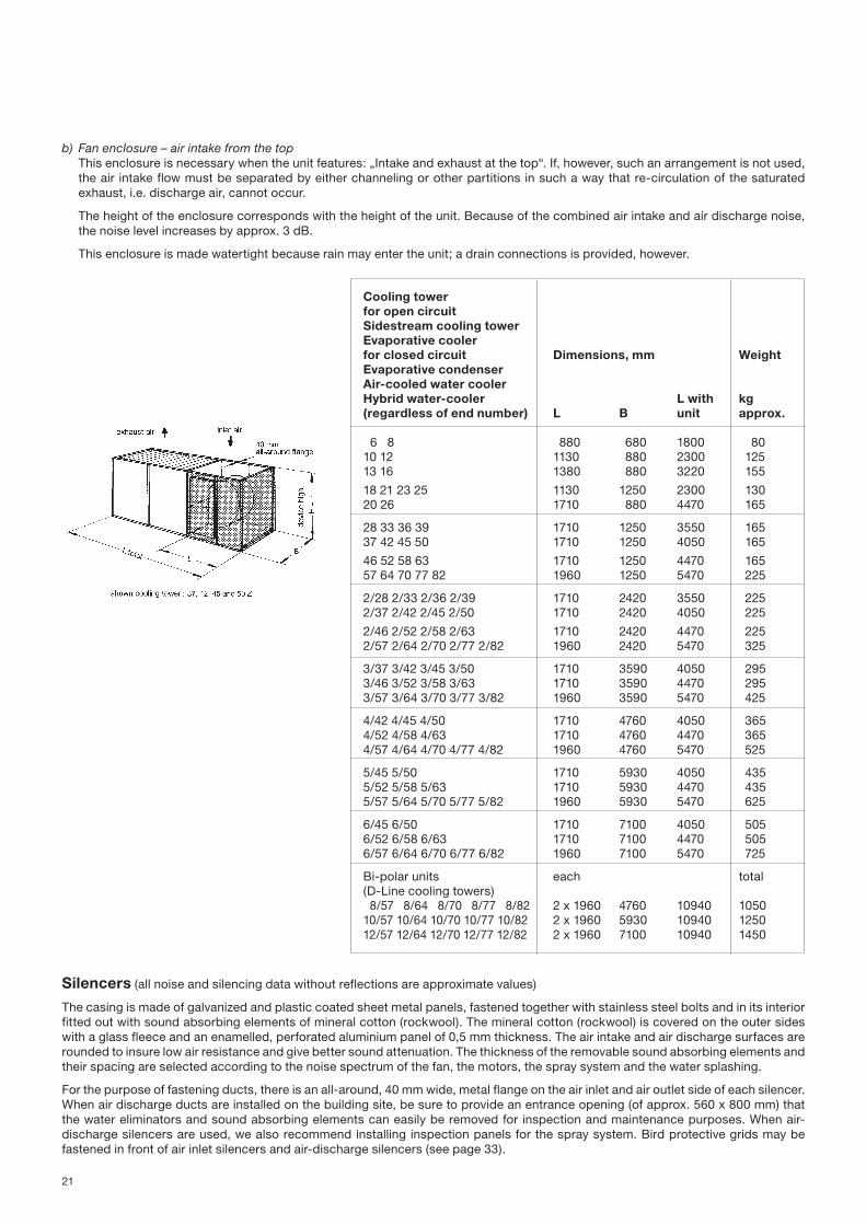
b) Fan enclosure – air intake from the top This enclosure is necessary when the unit features: „Intake and exhaust at the top“. If, however, such an arrangement is not used, the air intake flow must be separated by either channeling or other partitions in such a way that re-circulation of the saturated exhaust, i.e. discharge air, cannot occur.
The height of the enclosure corresponds with the height of the unit. Because of the combined air intake and air discharge noise, the noise level increases by approx. 3 dB.
This enclosure is made watertight because rain may enter the unit; a drain connections is provided, however.
Silencers (all noise and silencing data without reflections are approximate values)
The casing is made of galvanized and plastic coated sheet metal panels, fastened together with stainless steel bolts and in its interior fitted out with sound absorbing elements of mineral cotton (rockwool). The mineral cotton (rockwool) is covered on the outer sides with a glass fleece and an enamelled, perforated aluminium panel of 0,5 mm thickness. The air intake and air discharge surfaces are rounded to insure low air resistance and give better sound attenuation. The thickness of the removable sound absorbing elements and their spacing are selected according to the noise spectrum of the fan, the motors, the spray system and the water splashing.
For the purpose of fastening ducts, there is an all-around, 40 mm wide, metal flange on the air inlet and air outlet side of each silencer. When air discharge ducts are installed on the building site, be sure to provide an entrance opening (of approx. 560 x 800 mm) that the water eliminators and sound absorbing elements can easily be removed for inspection and maintenance purposes. When air-discharge silencers are used, we also recommend installing inspection panels for the spray system. Bird protective grids may be fastened in front of air inlet silencers and air-discharge silencers (see page 33).
Cooling towerfor open circuitSidestream cooling towerEvaporative coolerfor closed circuit Dimensions, mm WeightEvaporative condenserAir-cooled water coolerHybrid water-cooler L with kg(regardless of end number) L B unit approx.
6 8 880 680 1800 8010 12 1130 880 2300 12513 16 1380 880 3220 155
18 21 23 25 1130 1250 2300 13020 26 1710 880 4470 165
28 33 36 39 1710 1250 3550 16537 42 45 50 1710 1250 4050 165
46 52 58 63 1710 1250 4470 16557 64 70 77 82 1960 1250 5470 225
2/28 2/33 2/36 2/39 1710 2420 3550 2252/37 2/42 2/45 2/50 1710 2420 4050 225
2/46 2/52 2/58 2/63 1710 2420 4470 2252/57 2/64 2/70 2/77 2/82 1960 2420 5470 325
3/37 3/42 3/45 3/50 1710 3590 4050 2953/46 3/52 3/58 3/63 1710 3590 4470 2953/57 3/64 3/70 3/77 3/82 1960 3590 5470 425
4/42 4/45 4/50 1710 4760 4050 3654/52 4/58 4/63 1710 4760 4470 3654/57 4/64 4/70 4/77 4/82 1960 4760 5470 525
5/45 5/50 1710 5930 4050 4355/52 5/58 5/63 1710 5930 4470 4355/57 5/64 5/70 5/77 5/82 1960 5930 5470 625
6/45 6/50 1710 7100 4050 5056/52 6/58 6/63 1710 7100 4470 5056/57 6/64 6/70 6/77 6/82 1960 7100 5470 725
Bi-polar units each total(D-Line cooling towers) 8/57 8/64 8/70 8/77 8/82 2 x 1960 4760 10940 105010/57 10/64 10/70 10/77 10/82 2 x 1960 5930 10940 125012/57 12/64 12/70 12/77 12/82 2 x 1960 7100 10940 1450

22
Sound spectrum response of the sound pressure at dB for units without silencers with water spraying and full fan speed. To add or subtract of the sound pressure, which you can find in the prospect for the corresponding unit and selected external pressure.
Units Correction value for octave band-medium frequency 63 Hz 125 Hz 250 Hz 500 Hz 1000 Hz 2000 Hz 4000 Hz 8000 Hz
6, 8, 10, 12, 13, 16 - 4 - 8 - 3 - 4 - 6 - 8 - 7 - 12
all larger units + 2 - 4 - 3 - 4 - 6 - 8 - 11 - 15
Example: From brochure dt 25e, for cooling tower DT 82 Z at 80 to 130 Pa: sound pressure is 75 dB(A) at 3 m in extension of the fan shaft without silencers. The corresponding octaveband-analysis is:
for 63 Hz 74 + 2 = 76 dB 125 Hz 74 – 4 = 70 dB 250 Hz 74 – 3 = 71 dB
Attenuation of the sound absorbing elements (flow-direction) length is:
The attenuation of a unit´s housing walls is approx. 18 to 20 dB. Silencers of more than 1 m element length are, therefore, useful where the units are set up in a room and are in contract with the outside air by the air-intake and air-discharge silencers only, or in cases where the sides of the unit are noise enclosed.
The foundations for air intake silencers are to be extended underneath the unit in accordance with the existing type of foundation arrangement.
a) Standard air-intake silencer and standard air-discharge silencer
The standard fan enclosure is necessary for connecting the air-intake silencer with the unit. Where as the air-discharge silencers are watertight the air-intake silencers are not. The air-intake silencers, up to a width of 2420 mm can be built onto a fan enclosure. Air-intake silencers and air-discharge silencers can also be shipped as separate parts. If the parts are wider than 2420 mm, they can only be shipped disassembled in parts.
Octavo-medium frequency, Hz 63 125 250 500 1000 2000 4000 8000 total-attenuation
Sound abs. elements of 0,5 m length;attenuation, dB 1 2 6 10 18 22 16 8 11 up to max. 12
Sound abs. elements of 1,0 m lenght; dB total 2 4 12 20 34 40 32 16 16 up to max. 18
Sound abs. elements of 1,5 m lenght; dB total 3 6 17 30 44 50 42 24 17 up to max. 20
Dimension Dimension Pressure los Weight Lz Ha mm mm Pa Air-intake silencers Air-discharge silencers
Length of sound abs.elements 0,5 m 690 750 acc. to table acc. to table acc. to table
Length of sound abs.elements 1,0 m 1170 1170 1,2-multiple 1,8-multiple 1,7-multiple
Length of sound abs.elements 1,5 m 1620 1730 1,4-multiple 2,3-multiple 2,3-multiple
At air-cooled cooler the dimension Ha is 0 or 560 or 1170 mm.

23
D-Line Evaporative cooler Noise level when silencers have Dimensions Air-intake silencers Air-discharge silencercooling- for closed circuit sound absorbing elements of 0,5 m (when 0,5 m long sound absorbing (without fan enclosure)tower Evaporative condenser lenght at measuring points, in dB(A) elements) (approx. value) mm Weight Pressure Weight Pressure loss loss A B C D Ltotal Bz Hzv La kg Pa kg Pa
6 8 8/5 8/6 8/7 47 45 45 42 2240 680 1750 920 65 2 60 1210 47 45 45 44 2660 880 1750 1170 70 2 70 10
12 12/5 12/6 12/7 50 47 46 48 2660 880 1750 1170 70 3 70 1813 16 16/5 16/6 16/7 47 48 45 45 3330 880 1750 1840 70 5 95 15
18 21 50 48 48 48 2780 1250 1750 1170 100 5 100 1123 25 55 51 51 54 2780 1250 1750 1170 100 7 100 17
20 50 48 48 47 4370 880 1750 2760 80 10 140 12 26 26/5 26/6 26/7 52 49 49 51 4370 880 1750 2760 80 15 140 17
28 33 52 53 50 50 4180 1250 1750 1840 100 9 135 1236 54 55 52 53 4180 1250 1750 1840 100 13 135 1739 33/5 33/6 33/7 57 56 53 57 4180 1250 1750 1840 100 16 135 22
37 42 54 54 53 54 4680 1250 1750 2340 100 13 160 1245 50 45/5 45/6 45/7 59 55 55 59 4680 1250 1750 2340 100 32 160 20
46 53 55 52 53 5100 1250 1750 2760 100 15 195 952 58 52/5 52/6 52/7 59 56 55 59 5100 1250 1750 2760 100 33 195 1463 63 58 55 63 5100 1250 1750 2760 100 47 195 22
57 54 55 52 52 6180 1250 2000 3510 125 16 235 864 56 56 52 55 6180 1250 2000 3510 125 26 235 11
70 77 77/5 77/6 77/7 59 57 54 59 6180 1250 2000 3510 125 45 235 1882 62 58 55 62 6180 1250 2000 3510 125 75 235 25
2/33 54 53 53 52 4180 2420 1750 1840 175 9 215 122/36 57 54 53 54 4180 2420 1750 1840 175 13 215 172/39 2/33/5 2/33/6 2/33/7 60 56 55 59 4180 2420 1750 1840 175 16 215 22
2/37 2/42 56 54 53 55 4680 2420 1750 2340 175 13 260 122/45 2/50 2/45/5 2/45/6 2/45/7 62 55 54 62 4680 2420 1750 2340 175 32 260 20
2/46 56 55 53 55 5100 2420 1750 2760 175 15 315 92/52 2/58 2/52/5 2/52/6 2/52/7 62 56 54 61 5100 2420 1750 2760 175 33 315 142/63 65 58 56 64 5100 2420 1750 2760 175 47 315 22
2/57 54 55 53 50 6180 2420 2000 3510 205 16 375 82/64 58 56 53 57 6180 2420 2000 3510 205 26 375 11
2/70 2/77 2/77/5 2/77/6 2/77/7 62 56 55 61 6180 2420 2000 3510 205 45 375 182/82 64 57 56 63 6180 2420 2000 3510 205 75 375 25
3/37 3/42 58 55 55 56 4680 3590 1750 2340 255 13 360 123/45 3/50 3/45/5 3/45/6 3/45/7 63 57 56 62 4680 3590 1750 2340 255 32 360 20
3/46 57 55 55 56 5100 3590 1750 2760 255 15 440 9 3/52 3/58 3/52/5 3/52/6 3/52/7 63 56 56 62 5100 3590 1750 2760 255 33 440 143/63 66 57 57 65 5100 3590 1750 2760 255 47 440 22
3/57 55 55 55 53 6180 3590 2000 3510 285 16 515 83/64 59 56 56 58 6180 3590 2000 3510 285 26 515 11
3/70 3/77 3/77/5 3/77/6 3/77/7 63 57 57 62 6180 3590 2000 3510 285 45 515 183/82 65 58 58 64 6180 3590 2000 3510 285 75 515 25
4/42 59 53 55 58 4680 4760 1750 2340 330 13 455 12 4/45 4/50 64 57 56 63 4680 4760 1750 2340 330 32 455 20
4/52 4/58 64 57 56 63 5100 4760 1750 2760 330 33 570 144/63 67 58 58 67 5100 4760 1750 2760 330 47 570 22
4/57 55 55 55 54 6180 4760 2000 3510 365 16 665 84/64 59 56 56 58 6180 4760 2000 3510 365 26 665 11
4/70 4/77 4/77/5 4/77/6 4/77/7 63 57 57 62 6180 4760 2000 3510 365 45 665 184/82 65 58 58 64 6180 4760 2000 3510 365 75 665 25
5/45 5/50 65 57 56 64 4680 5930 1750 2340 405 32 555 20
5/52 5/58 65 57 56 64 5100 5930 1750 2760 405 33 690 145/63 68 59 58 68 5100 5930 1750 2760 405 47 690 22
5/57 55 55 55 54 6180 5930 2000 3510 445 16 810 85/64 59 56 56 58 6180 5930 2000 3510 445 26 810 11
5/70 5/77 5/77/5 5/77/6 5/77/7 63 57 57 62 6180 5930 2000 3510 445 45 810 18 5/82 65 58 58 64 6180 5930 2000 3510 445 75 810 25
6/45 6/50 65 57 56 64 4680 7100 1750 2340 480 32 650 20
6/52 6/58 65 57 56 64 5100 7100 1750 2760 480 33 820 146/63 68 59 58 68 5100 7100 1750 2760 480 47 820 22
6/57 56 55 55 55 6180 7100 2000 3510 525 16 960 86/64 60 56 56 59 6180 7100 2000 3510 525 26 960 11
6/70 6/77 6/77/5 6/77/6 6/77/7 64 57 57 63 6180 7100 2000 3510 525 45 960 186/82 66 58 58 65 6180 7100 2000 3510 525 75 960 25
8/57 55 55 -- 54 12360 4760 2000 3510 2x365 16 2x665 88/64 59 56 -- 58 12360 4760 2000 3510 2x365 26 2x665 11
8/70 8/77 63 57 -- 62 12360 4760 2000 3510 2x365 45 2x665 188/82 65 58 -- 64 12360 4760 2000 3510 2x365 75 2x665 25
10/57 55 55 -- 54 12360 5930 2000 3510 2x445 16 2x810 8 10/64 59 56 -- 58 12360 5930 2000 3510 2x445 26 2x810 11
10/70 10/77 63 57 -- 62 12360 5930 2000 3510 2x445 45 2x810 1810/82 65 58 -- 64 12360 5930 2000 3510 2x445 75 2x810 25
12/57 56 55 -- 55 12360 7100 2000 3510 2x525 16 2x960 812/64 60 56 -- 59 12360 7100 2000 3510 2x525 26 2x960 11
12/70 12/77 64 57 -- 63 12360 7100 2000 3510 2x525 45 2x960 1812/82 66 58 -- 65 12360 7100 2000 3510 2x525 75 2x960 25
24
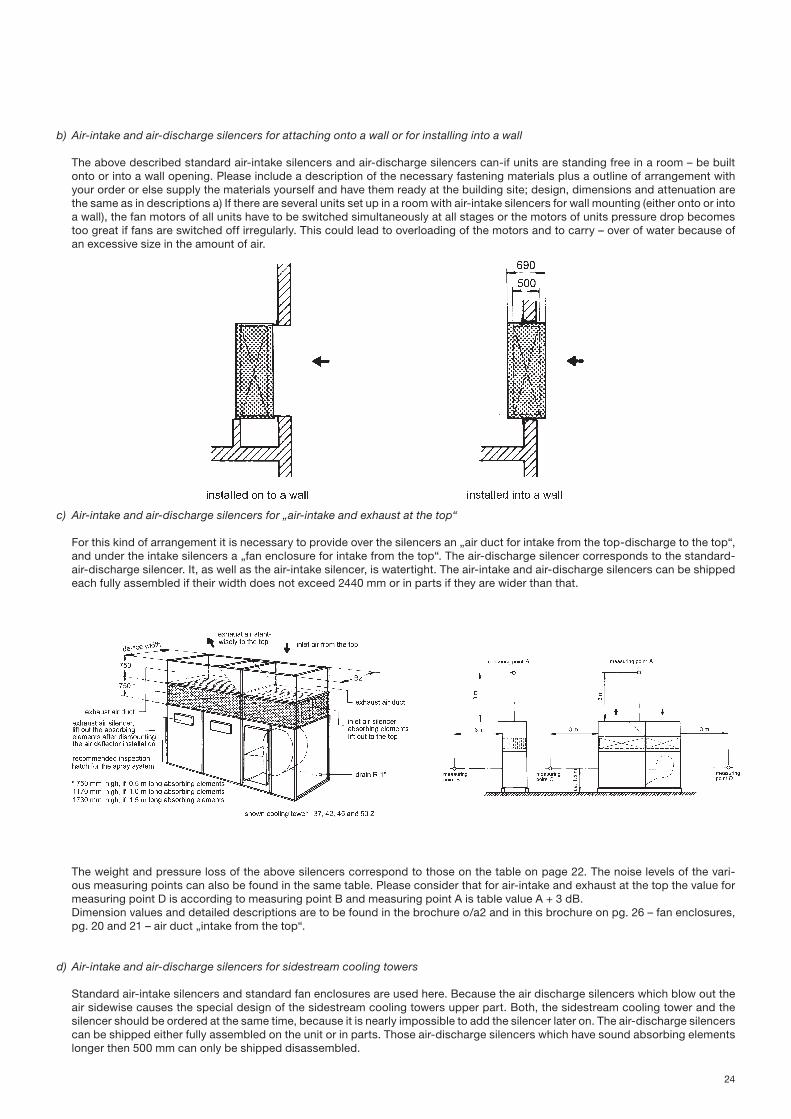
b) Air-intake and air-discharge silencers for attaching onto a wall or for installing into a wall The above described standard air-intake silencers and air-discharge silencers can-if units are standing free in a room – be built onto or into a wall opening. Please include a description of the necessary fastening materials plus a outline of arrangement with your order or else supply the materials yourself and have them ready at the building site; design, dimensions and attenuation are the same as in descriptions a) If there are several units set up in a room with air-intake silencers for wall mounting (either onto or into a wall), the fan motors of all units have to be switched simultaneously at all stages or the motors of units pressure drop becomes too great if fans are switched off irregularly. This could lead to overloading of the motors and to carry – over of water because of an excessive size in the amount of air.
c) Air-intake and air-discharge silencers for „air-intake and exhaust at the top“
For this kind of arrangement it is necessary to provide over the silencers an „air duct for intake from the top-discharge to the top“, and under the intake silencers a „fan enclosure for intake from the top“. The air-discharge silencer corresponds to the standard-air-discharge silencer. It, as well as the air-intake silencer, is watertight. The air-intake and air-discharge silencers can be shipped each fully assembled if their width does not exceed 2440 mm or in parts if they are wider than that.
The weight and pressure loss of the above silencers correspond to those on the table on page 22. The noise levels of the vari-ous measuring points can also be found in the same table. Please consider that for air-intake and exhaust at the top the value for measuring point D is according to measuring point B and measuring point A is table value A + 3 dB.Dimension values and detailed descriptions are to be found in the brochure o/a2 and in this brochure on pg. 26 – fan enclosures, pg. 20 and 21 – air duct „intake from the top“.
d) Air-intake and air-discharge silencers for sidestream cooling towers
Standard air-intake silencers and standard fan enclosures are used here. Because the air discharge silencers which blow out the air sidewise causes the special design of the sidestream cooling towers upper part. Both, the sidestream cooling tower and the silencer should be ordered at the same time, because it is nearly impossible to add the silencer later on. The air-discharge silencers can be shipped either fully assembled on the unit or in parts. Those air-discharge silencers which have sound absorbing elements longer then 500 mm can only be shipped disassembled.

25
see brochure sst 5
Sidestream Noise level if silencers have sound Dimensions Air-intake and air-cooling tower absorbing elements of 500 mm (with sound absorbing elements discharge silencers at the measuring points, in dB(A) of 500 mm) with fan enclosures mm
Weight Pressure loss incl. units external
A B C D Ltotal Lzvg B H kg total Pa
28 33 51 53 52 49 4930 4180 1250 2390 1220 6036 51 53 54 51 4930 4180 1250 2390 1220 8039 51 53 56 54 4930 4180 1250 2390 1220 10037 42 53 53 55 51 5430 4680 1250 2390 1320 8045 53 53 57 55 5430 4680 1250 2390 1320 10050 53 53 59 57 5430 4680 1250 2390 1320 1202/28 2/33 54 53 54 54 4930 4180 2420 2390 2230 602/36 54 53 56 56 4930 4180 2420 2390 2230 802/39 54 53 58 58 4930 4180 2420 2390 2230 1002/37 2/42 54 53 57 53 5430 4680 2420 2390 2400 802/45 54 53 59 56 5430 4680 2420 2390 2400 1002/50 54 53 61 58 5430 4680 2420 2390 2400 120
e) Silencers for air-cooled water cooler
Sound absorbing elements for silencers
The sound absorbing elements can be used for installing into air-intake and air-discharge channels, onto a wall or into a wall, indoors or outdoors, for horizontal or vertical flow of air.The sound absorbing elements are resistible against corrosion, weatherproof, resistant to uv-radiation, cold, heat and humidity, fire-proof and resistant to abrasion to approx. 12 m/s air flow rate.The sound absorbing element is made of mineral cotton (rockwool). The mineral cotton (rockwool) is covered on the outer sides with a glass fleece and an enamelled, perforated aluminium panel of 0,5 mm thickness. The air-intake and air-discharge surfaces are rounded to insure low air resistance and give better attenuation. It will be used the same construction as for the cooling tower silencers.
Dimensions for the elements:Width (B) mm 836, 1086, 1336, 1666, 1711, 1756, 1916, 2256, 2676, 3426Intermediate-sizes possible by a order of min. 50 elements per size.

26
Deflector plate for air intake and air discharge at the top
By installing the deflector plate (separate diagonal metal sheets) between the sound absorbing elements of the discharge silencer, the bulky duct connecting piece for unit air intake and discharge at the top is unnecessary by still serving its purpose. The reflector plate is made of galvanized plastic coated sheet.
Duct connecting piece for air-intake and air-discharge at the top
It is necessary to install this type of air duct in situations where the cooling air is taken in from the top and also discharged to the top. It prevents air recycling, a mishap which would cause inefficient unit performance. The use of the air duct “intake from the top-dis-charge to the top” is ideal if a unit has to be set up, for instance, in an attic room without side openings or in a hole in the ground, in a tight spot or at places where noise to the sides would be less desirable than to the top.This air duct is made of galvanized, plastic coated sheet metal panels, fastened together with bolts watertight. The specially arranged metal partition between the air-intake and air-discharge side forces the saturated air out in a directed manner to the top. Its upper and lower side are outfitted with an all-around flange. The pressure loss amounts to approx. 20 to 40 Pa.For more detailed information see Technical report No. 16 as well as page 21, b) fan enclosures, and page 24, silencers “air intake from the top – air discharge to the top” of this brochure.The air duct “air intake from the top – air discharge to the top” can be shipped as one separate assembled piece (also possible as an assembled piece with silencers) up to a maximum width of 2420 mm or, if wider, disassembled into parts.
* for bipolar units (8/.../B, 10/.../B, 12/.../B) two duct connecting pieces for each size units with 4 cells and more have two inspection doors.
Cooling tower DT Maintenance duct Duct connectingEvaporative cooler VK piece for Evaporative condenser VV air intake and air (regardless of end number), discharge at the topAir-cooled cooler LWHybrid cooler HK Dimensions Weight Dimensions Weight mm mm A B kg L Bz Kg 6 8 1800 680 95 10 12 2300 880 115 13 16 3220 880 145
18 21 23 25 2300 1250 150 1170 1250 8520 26 4470 880 185 28 33 36 39 3550 1250 190 1840 1250 10537 42 45 50 4050 1250 210 2340 1250 12046 52 58 63 4470 1250 225 2760 1250 13057 64 70 77 82 5470 1250 265 3510 1250 150
2/33 2/36 2/39 3550 2420 280 1840 2420 1402/37 2/42 2/45 2/50 4050 2420 305 2340 2420 1502/46 2/52 2/58 2/63 4470 2420 325 2760 2420 1652/57 2/64 2/70 2/77 2/82 5470 2420 375 3510 2420 185
3/37 3/42 3/45 3/50 4050 3590 440 2340 3590 1903/46 3/52 3/58 3/63 4470 3590 470 2760 3590 2003/57 3/64 3/70 3/77 3/82 5470 3590 550 3510 3590 220
4/42 4/45 4/50 4050 4760 535 2340 4760 2304/52 4/58 4/63 4470 4760 570 2760 4760 2404/57 4764 4/70 4/77 4/82* 5470 4760 660 3510 4760 260
5/45 5/50 4050 5930 665 2340 5930 2705/52 5/58 5/63 4470 5930 715 2760 5930 2805/57 5/64 5/70 5/77 5/82* 5470 5930 810 3510 5930 300
6/45 6/50 4050 7100 760 2340 7100 3106/52 6/58 6/63 4470 7100 815 2760 7100 3206/57 6/64 6/70 6/77 6/82* 5470 7100 925 3510 7100 340

27
Maintenance duct
a) Maintenance duct for air-discharge
The insertion of the duct connecting piece is often necessary when other duct components, such as air-discharge silencers, air-discharge dampers or difficult accessible channels are to be installed on a unit. An inspection door in this section of the duct and on the side of the fans allows accessibility to the upper part of the unit for maintenance purposes, i.e. for exchanging of the water eliminators and the spray system (inspection panels may suffice for smaller units). The connecting piece, made of 1,5 to 2 mm thick galvanized, and plastic coated sheet metal panels, is bolted together in a watertight manner. An all-around 40 mm wide flange on its upper and lower edge is for fastening means to other channels. The resulting pressure loss is negligible.
b) Maintenance duct for air-intake and air discharge at the top
This maintenance duct is only for the cooling tower air-intake and air-discharge at the top. Its dimensions and weights are corresponding with the duct connecting piece for air-intake – air-discharge at the top and its performance corresponds with the maintenance duct for air-discharge. Between the air-intake and air-discharge is a metal partition panel. The maintenance door is fitted at the long side of air-discharge. The pressure loss is negligible.
c) Maintenance duct for air-intake
This maintenance duct is placed between the fan enclosure and inlet silencer or the duct connecting piece for air-intake. It will be recom-mended for units with more than one fan. The entrance inspection panel allows accessibility to the fan and belt drive for maintenance pur-poses.The maintenance duct for air-intake is made of 1,5 to 2 mm thick gal-vanized, plastic coated sheet metal panels which are fastened together with stainless steel bolts. An all-around 40 mm wide flange on its side serves as a fastening means to other channels. The pressure loss is negligible. This maintenance duct its not watertight. The weight is approx. 80 % of the standard inlet silencer (see page 23).
d) Duct connecting piece for air-intake from the top
This duct connecting piece is placed between fan enclosure air-intake at the top and other channels by using f.e. silencers, finned heat exchanger or a discharge damper.The duct connecting piece for air-intake from the top made of 1,5 to 2 mm thick galvanized, plastic coated sheet metal panel, is bolted together in a watertight manner. A 40 mm wide flange on its upper and lower side as well on the back side serves as a fastening means to the units and other channels. The pressure loss is negligible.

28
Exhaust air hood
The exhaust air hood, a narrowing channel connection, makes it possible to turn the discharge air and noise either to the right or left side of the unit. It can be installed directly on top of unit on a discharge silencer or a duct connecting piece. In order to inspect the spray nozzles . in a combination unit of air-discharge hood and discharge silencer, the slanted separation panel, the sound absorbing elements and the water eliminators must be removed if there are no inspection panels.The air discharge hood made of galvanized and plastic coated sheet metal panels is bolted together in a watertight manner. A 40 mm wide all-around flange on its air-intake and air discharge sides is for fastening means to the unit, to channels, walls etc.. The resulting pressure loss amounts to between 10 and 40 Pa, depending whether it’s a beginning or ending unit of the same size.
Cooling tower DT, Dimensions WeightEvaporative cooler VK, mmEvaporativecondenser VV, Air cooled cooler, Hybrid cooler(regardless ofend number) A B C D E kg
6 8 686 920 436 546 796 3010 12 686 1170 436 546 796 5013 16 686 1843 436 546 796 50
18 21 23 25 1256 1170 686 796 1366 9020 26 686 2766 436 546 796 7028 33 36 39 1256 1846 686 796 1366 11537 42 45 50 1256 2343 686 796 1366 12046 52 58 63 1256 2766 686 796 1366 16057 64 70 77 82 1256 3516 686 796 1366 175
2/28 2/33 2/36 2/39 2429 1843 1286 1396 2539 1902/37 2/42 2/45 2/50 2429 2343 1286 1396 2539 2002/46 2/52 2/58 2/63 2429 2766 1286 1396 2539 2502/57 2/64 2/70 2/77 2/82 2429 3516 1286 1396 2539 280
3/37 3/42 3/45 3/50 3602 2343 1836 1946 3712 3003/46 3/52 3/58 3/63 3602 2766 1836 1946 3712 3503/57 3/64 3/70 3/77 3/82 3602 3516 1836 1946 3712 400
The exhaust air hood may be shipped assembled as a separate part or in sections.
Exhaust air deflector hood
The discharge air will be turned to the water connection side of the unit to prevent recirculation of heated discharge air into the air intake or to turn away the discharge air form a building. It can be installed directly on top of the unit, on a discharge silencer or a maintenance duct. The discharge deflector hood in made of 1,5 to 2 mm thickness galvanized, plastic coated sheet metal panel, fastened together with bolts. Its upper side is outfitted with a 40 mm wide flange. The pressure loss is negligible.

29
Exhaust air nozzle
The exhaust air stack like duct, reduces itself to the top accelerates the air discharge considerably and prevents air recycling and fog formation near the unit.The exhaust air nozzle is made of galvanized, plastic coated sheet metal panels which are bolted together in a watertight manner. A 40 mm wide all-around flange (turned outwards) serves as a fastening means to the unit and to channels. The slanted side panel(s) can be removed for inspection and repair purposes, nevertheless we recommend an installation of inspection hatches for the spray area.
Cooling towers; Evaporative cooler Dimensions Pressure WeightAir cooled cooler; for closed circuit; mm loss Hybrid water cooler Evaporative condenser Pa kg(regardless of end number) A B C D approx. approx.
6 680 920 280 600 37 40 8 8/5 8/6 8/7 680 920 280 600 55 4010 12/5 680 1170 280 600 40 5012 12/6 12/7 680 1170 280 600 67 50
13 16/5 680 1840 280 600 37 7016 16/6 16/7 680 1840 280 600 55 7021 1250 1170 480 1170 40 10018 1250 1170 480 1170 26 10023 1250 1170 480 1170 50 10025 1250 1170 480 1170 67 100
20 26/5 26/6 26/7 680 2760 280 600 38 10026 680 2760 280 600 55 10028 1250 1840 480 1170 28 14033 33/5 33/6 33/7 1250 1840 480 1170 40 14036 1250 1840 480 1170 55 14039 1250 1840 480 1170 73 140
37 1250 2340 480 1170 30 17042 45/5 45/6 45/7 1250 2340 480 1170 40 17045 1250 2340 480 1170 55 17050 1250 2340 480 1170 70 17046 1250 2760 480 1170 28 19052 52/5 52/6 1250 2760 480 1170 40 19058 52/7 1250 2760 480 1170 53 19063 1250 2760 480 1170 70 190
57 1250 3510 480 1170 24 24064 1250 3510 480 1170 36 24070 77/5 77/6 77/7 1250 3510 480 1170 47 24077 1250 3510 480 1170 60 24082 1250 3510 480 1170 76 240
2/33 2/36 2/39 2/33/5 2/33/6 2/33/7 2420 1840 880 1170 for 2502/37 2/42 2/45 2/50 2/45/5 2/45/6 2/45/7 2420 2340 880 1170 units 3002/46 2/52 2/58 2/63 2/52/5 2/52/6 2/52/7 2420 2760 880 1170 with 1 3402/57 2/64 2/70 2/77 2/82 2/77/5 2/77/6 2/77/7 2420 3510 880 1170 fan 400

30
Flexible duct connection
The flexible duct connection serves the purpose of eliminating noise propagation from the unit. It consists of an aluminium angle frame into which an elastic, PVC coated material is fastened. This frame is for the connection with the unit (or an air-discharge silencer, exhaust air hood, or an exhaust air nozzle) and the air-discharge channel (or a wall, ceiling or a wall cut-out).
The dimensions are in accord with the connecting flanges of the unit´s discharge open-ings, the air-discharge silencer, the duct connecting piece and others. Other dimensions will be supplied upon request.
The flexible duct connection may be shipped assembled or in parts up to size 2/82; sizes beyond that may be shipped in parts only.
Cooling tower; Air-discharge Air-intakeEvaporative cooler; (air intake from the side)Evaporative condenser;Air-cooled unit; Dimensions Weight Dimensions Weight Hybrid water cooler mm mm (regardless of end number) L B kg L B kg
6 8 920 680 10 1750 680 2010 12 1170 680 12 1750 880 24
13 16 1840 680 16 1750 880 3218 21 23 25 1170 1250 15 1750 1250 2320 26 2760 680 21 1750 880 17
28 33 36 39 1840 1250 19 1750 1250 1837 42 45 50 2340 1250 22 1750 1250 17
46 52 58 63 2760 1250 19 1750 1250 1257 64 70 77 82 3510 1250 29 2000 1250 172/33 2/36 2/39 1840 2420 26 1750 2420 252/37 2/42 2/45 2/50 2340 2420 29 1750 2420 22
2/46 2/52 2/58 2/63 2760 2420 32 1750 2420 212/57 2/64 2/70 2/77 2/82 3510 2420 36 2000 2420 21
3/37 3/42 3/45 3/50 2340 3590 36 1750 3590 273/46 3/52 3/58 3/63 2760 3590 39 1750 3590 253/57 3/64 3/70 3/77 3/82 3510 3590 43 2000 3590 25
4/42 4/45 4/50 2340 4760 43 1750 4760 324/52 4/58 4/63 2760 4760 46 1750 4760 294/57 4/64 4/70 4/77 4/82 3510 4760 50 2000 4760 29
5/45 5/50 2340 5930 50 1750 5930 375/52 5/58 5/63 2760 5930 53 1750 5930 345/57 5/64 5/70 5/77 5/82 3510 5930 57 2000 5930 32
6/45 6/50 2340 7100 57 1750 7100 436/52 6/58 6/63 2760 7100 60 1750 7100 386/57 6/64 6/70 6/77 6/82 3510 7100 64 2000 7100 37
each side each side total 8/57 8/64 8/70 8/77 8/82 7020 4760 100 2000 4760 5810/57 10/64 10/70 10/77 10/82 7020 5930 114 2000 5930 6412/57 12/64 12/70 12/77 12/82 7020 7100 128 2000 7100 74
Sidestream Dimension Weight Dimension Weightcooling towers (with mm mmdischarge silencer) L B kg L B kg
28 33 36 39 1170 1250 19 1750 1250 2637 42 45 50 1170 1250 19 1750 1250 26
2/28 2/33 2/36 2/39 1170 2420 29 1750 2420 412/37 2/42 2/45 2/50 1170 2420 29 1750 2420 41
Air-discharge Air-intake
Sidestream Dimension Weight Dimension Weightcooling towers (without mm mmdischarge silencer) L B kg L B kg
28 33 36 39 820 1250 13 1750 1250 2637 42 45 50 820 1250 13 1750 1250 26
2/28 2/33 2/36 2/39 820 2420 20 1750 2420 412/37 2/42 2/45 2/50 820 2420 20 1750 2420 41
Air-discharge Air-intake

31
Exhaust air damper
The exhaust air damper consists of a housing which dimensions and shape correspond with the maintenance duct and the discharge cross section according to the exhaust air nozzle. It combines the advantages of the maintenance duct and the exhaust air nozzle by increasing the discharge air speed. The air damper moves at 90 degree. The main purpose is to prevent cold air from entering the discharge opening when the fan is switched off. Freezing of the cooling water in the unit, especially that of the primary circuit water if there is no antifreeze in the coil system of the evaporative coolers for closed circuit operation is eliminated when the fan is fitted with open-shut inlet air dampers and the water-basin is outfitted with an electric heating. It prevents air recycling and fog formation near the unit.
The wing panel of the damper consists of galvanized, plastic coated metal sheets and a galvanized pipe shaft of steel with ball bearings. In the open position the wing panel is max. 300 mm higher than the housing. It will be moved by a servomotor fixed on fan side. Data: 230 V, 50 Hz, IP 55 according to EN 60 529, 5W, opening/closing time approx. 150 s.. For one unit up to 3 cells activates one servomotor.The air inlet and discharge area of the damper opening at the evaporative cooler can be shut when the fan and secondary pump are out of operation and the water in the primary circuit will became to cold. The air inlet and discharge opening of the damper will be generally closed when the fan and secondary pump is out of operation of the cooling tower (both cooling towers DT and evaporative coolers).The servomotor activates the construction only when the damper wings are completely open. This damper ensures trouble-free operation. Air discharge dampers for 4 or more cells have two inspection panels.
Cooling tower; Evaporative cooler; Dimensions Pressure Weight Air cooled units Evaporative condenser mm loss (regardless of end number) L B Pa kg
6 920 680 15 45 8 8/5 8/6 8/7 920 680 33 45
10 12/5 1170 680 24 5512 12/6 12/7 1170 680 41 55
13 16/5 1840 680 22 7016 16/6 16/7 1840 680 33 70
21 1170 1250 27 10018 1170 1250 18 10023 1170 1250 33 10025 1170 1250 43 100
20 26/5 26/6 26/7 2760 680 23 11026 2760 680 33 110
28 1840 1250 18 14033 33/5 33/6 33/7 1840 1250 27 14036 1840 1250 36 14039 1840 1250 48 140
37 2340 1250 21 17042 45/5 45/6 45/7 2340 1250 27 17045 2340 1250 36 17050 2340 1250 46 170
46 2760 1250 18 19052 52/5 2760 1250 27 19058 52/6 52/7 2760 1250 36 19063 2760 1250 46 190
57 3510 1250 17 24064 3510 1250 24 24070 77/5 77/6 77/7 3510 1250 31 24077 3510 1250 41 24082 3510 1250 50 240
2/33 2/36 2/39 2/33/5 2/33/6 2/33/7 1840 2420 2602/37 2/42 2/45 2/50 2/45/5 2/45/6 2/45/7 2340 2420 as 3102/46 2/52 2/58 2/63 2/52/5 2/52/6 2/52/7 2760 2420 units 3502/57 2/64 2/70 2/77 2/82 2/70/5 2/77/6 2/77/7 3510 2420 with 1 400
3/37 3/42 3/45 3/50 3/45/5 3/45/6 3/45/7 2340 3590 fan 4503/46 3/52 3/58 3/63 3/52/5 3/52/6 3/52/7 2760 3590 5103/57 3/64 3/70 3/77 3/82 3/70/5 3/77/6 3/77/7 3510 3590 560

32
Inlet air damper „open-closed“
Units which operate in a room without fan, only water spray on, should be equipped with an „open-shut“ air damper. It prevents that the damp air enters the room through the idly fan of the unit and causes corrosion of the fan parts and condensation in the room.The Siemens-servomotor which activates the damper has to be locked in such a way with the fan motor that the air damper will close the connecting channel between the fan and the unit´s interior when the fan is shut off. The air damper moves by 90 degree. The Sie-mens-servomotor ensures trouble-free operation and exact opening and closing.The air damper consists of an air vane, made of aluminium, the cadmium plated shaft of steel which is enclosed within two mainte-nance-free polyamide bearing bushings, the “push-pull” servomotor, the end switch, the fastening material, and the hood cover for the servomotors for protection against the weather.
Cooling tower, Evaporative cooler, Siemens-servomotor Sidestream cooling Evaporative 230V; 50Hz tower, condenser Size of Pres- Absor- closing Weight Air cooled units dampers sure bed time loss power [Pa] [W] [s] [kg]
6 8 8/5 8/6 8/7 1 50 5 150 1110 12 12/5 12/6 12/7 2 50 5 150 1213 16 16/5 16/6 16/7 2 50 5 150 1218 21 23 25 3 50 5 150 1320 26 26/5 26/6 26/7 3 50 5 150 13
28 33 36 39 33/5 33/6 33/7 4 10 5 150 2037 42 45 50 45/5 45/6 45/7 4 10 5 150 2046 52 58 63 52/5 52/6 52/7 4 10 5 150 2057 64 70 77 82 70/5 77/6 77/7 5 10 5 150 21
All units with 2 or 3 fans 4 or 5 10 5 150
All units with 4, 5 or 6 fans 4 or 5 10 10 150have 2 Siemens-servomotors
All bipolar units have 4 Siemens-servomotors 5 10 20 150
Mul
tiple
1 Housing 2 Swing angle scale 0°...90° 4 Connection cable for supply 5 Connection cable for auxiliary switch 6 Releasing key for gear 7,8 Setting axles for auxiliary switch A and B 9 Position indicator10 Self-centring axle-adapter11 Screening ring for axle-adapter12 Twist safety device
Self-acting inlet-air damper
The self-acting inlet-air damper realizes the same purpose as the above described inlet air damper open-closed. It consists of an air vane made of aluminium, the cadmium plated shaft of steel which is enclosed within two maintenance-free polyamide bearing and additional with a balancing weight. See illustration. When the fan started the damper will be opened through the air flow and the balancing weights.
The weight of the self-acting inlet damper in correspondence with the weight of the inlet air damper open-closed (instead of the 2 kg heavy ser-vomotor we have the balancing weight).
pressure loss Unit-sizeof the self-acting 6 - 26 24 - 82
inlet-air damper [PA] 30 - 60 20 - 50
Each air-discharge connection piece is fitted out with one damper. One ser-vomotor activates up to 3 air-dampers which shafts are couplings in units with several fans. By shipping the units with dampers the air vane out servomotor is already mounted.Siemens-servomotor rotation drive with mechanical lifetime of 105 cycles

33
Bird protective grid
In order to prevent foreign bodies like leaves, birds etc. to enter the unit´s interior (by fan suction, by falling on or through the water eliminators), we recommend the installation of a bird protective grid. These guards are welded of 2,5 mm thick wire; mesh width 40 x 20 mm. They are galvanized, and fastened in the cross section of flow of the fan enclosures or air-intake silencers, above air-discharge silencers, exhaust air hoods, exhaust air nozzles and air-duct-intake from the top. If the air-intake side of a standard fan enclosure is freely accessible a bird protec-tive grid is absolutely necessary for the prevention of accidents at the fan drive. These guards are cut into lengths and edged on two sides approx. 40 mm at 90 degree. They can be fastened with parker screws at the duct walls or in front of the silencers on the sound absorbing elements. These guards can be removed easily to permit access to the interior of the unit or duct for inspection purposes. Please note: The bird protective grids are not passable.
Air filter mats
The air-filter mats are for the purpose of cleaning the intake-air from dirt (pollen, sand, etc.) keeping the fan drive, but especially the circulating cooling water, cleaner. A dust-free level of 66 %, acc. to ASHRAE standards, is achieved. The pressure loss at low to medium dirt accumulation amounts to approx. as much as is shown on page 23 of the table for air-intake and air-discharge silencers together.
The air-filter mats include the described bird protective grids above. They are placed into the bird-guard grating in such a way that they cover the entire intake cross section and held with a second, smaller grating. Both gratings, the filter mat between them, are fastened together with wire loops. The entire package is fastened with Parker screws in the fan enclosure or in the air-intake silencer.
Anti-vibration railsWhen ordering units with anti-vibration please specify if the units are to be set on a longitudinal or cross foundations.
Anti-vibration rails counteract noise from vibrations downward mostly efficient if they are sectioned off in such a way that the omega-profile of stainless steel, coated with an anti-noise compound gives 3 to 4 mm, out of thickness of 40 mm, under the operating weight of the cooling tower. The sound absorbing effect of these spring-like rails sets in at a frequency range of 20 Hz provided, of course, that the rigid pipe connections are neutralized by compensators. We also supply a rubber hose of 500 mm length. It eliminates the hammer noise of the float valve by providing an elastic connection of the fresh-water inlet with the supply line. When ordering units with anti-vibration rails which are to be set on a cross-foun-dation (i.e. parallel to the fan shaft) but not on platforms or longitudinal founda-tions, please specify.
Neoprene rubber-strips
The 10 mm high neoprene rubber strips are essentially for the same purpose as the anti-vibration rails. They counteract noise propagation. We glue the variably sectioned ribbons to the longitudinal supports of the unit. While the rail-like, lon-gitudinally corrugated side faces the foundation, the cross notched side serves as a gluing surface. At optimal sectioning of the rubber strips, recognizable by a 2 mm thick compressibility of the rubber, effectiveness starts of a frequency range of 75 Hz. A rubber hose is not included in the shipment.Please specify does the units are on a longitudinal or cross foundation.
Structure-borne sound insulation (Anti-vibration [absorbing] elements)
and fastening devices

34
Wide flange I-beam IPB / HEB (hot-dip galvanized)
In situations where the question of body noise propagation is unimportant, double I-beams offer a good means of support for the unit. Fastening to the unit supports the wide flange beams and foundation is best accomplished with brackets and bolts.
IPB / HEB 100 – Weight: 21 kg/m.IPB / HEB 120 – Weight: 27,5 kg/m.IPB / HEB 140 – Weight: 34,5 kg/m.
Base frames of IPB / HEB (hot-dip galvanized)
Base frame for one cell or more cell cooling towers will be made by IPB / HEB.It`s welded or screwed. The fastening to the unit supports base frame and foun-dation in best accomplished with brackets and bolts.
Weights per m see IPB / HEB I-beam above.
Clamping claws/Lindapter – clamping claws
The units as well as the unit supports may be fastened with brackets. A hole in the foot of this metal device receives the bolt while the bracket´s arm fits over the edging of the unit´s side plate or over existing anti-vibration rails. The foundation has to be wider. The claw is made of steel flat painted without screws.
The Lindapter-clamping claws are especially for using the IPB / HEB beams. They consist of bracket washer clamping claw and screwing. The anti-vibration rails of the cooling tower will be fastened to the IPB / HEB beams. See illustration. The dimensions of the brackets depend on the size of the IPB / HEB beams.

35
Double elastic support to counteract noise propagation
The fans and the fan motor are together on a base frame. The fans are connected to the cooling tower housing with flexible duct connections. The base frame is supported on steel springs. The whole cooling tower will be set additional on anti-vibration rails or neoprene rubber strips therefore double elastic support.
Reverse flange
The reversing flange is used if the assembly of accessories (for example duct connecting pieces, silencers etc.) is not possible from outside the cooling tower. The reversing flange consists of two sections which are assembled from inside using stainless steel bolts and a permanently flexible sealing compound.
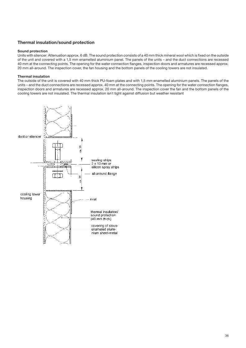
36
Thermal insulation/sound protection
Sound protectionUnits with silencer: Attenuation approx. 6 dB. The sound protection consists of a 40 mm thick mineral wool which is fixed on the outside of the unit and covered with a 1,5 mm enamelled aluminium panel. The panels of the units – and the duct connections are recessed 40 mm at the connecting points. The opening for the water connection flanges, inspection doors and armatures are recessed approx. 20 mm all-around. The inspection cover, the fan housing and the bottom panels of the cooling towers are not insulated.
Thermal insulationThe outside of the unit is covered with 40 mm thick PU-foam plates and with 1,5 mm enamelled aluminium panels. The panels of the units – and the duct connections are recessed approx. 40 mm at the connecting points. The opening for the water connection flanges, inspection doors and armatures are recessed approx. 20 mm all-around. The inspection cover the fan and the bottom panels of the cooling towers are not insulated. The thermal insulation isn`t tight against diffusion but weather resistant

37
Inspection hatch for spray system (clear opening 600 x 270 mm)
We recommend the installation of an inspection hatch for access to the spray area in situations where it is difficult to get to the spray nozzles via the air discharge opening because of blockage by air-ducts, channels or installation into a wall opening. The spray nozzles in the upper part of a unit with one or two fans can be removed for maintenance purposes by reaching in with tools. Installation of a duct connecting piece offers, however, better accessibility (see page 26/27).The inspection hatch consists of a welded sectional frame which is plastic coated and fixed on the unit in a water tight manner. The cover is made of galvanized, and plastic coated sheet metal panel. It`s bolted together with the frame with knob grip nuts. The number of inspection panels depends on the desired inspection possibilities. Depending on the size of a unit, there can be installed one inspection hatch of each cooling tower casing panel.
Inspection hatch for hybrid water-cooler (clear opening 560 x 350 mm)
We recommend the installation of an inspection hatch for access to the spray area. Design see description of the inspection hatch for spray system.
Inspection hatch for water-basin (clear opening 350 x 350 mm or 490 x 350 mm)
The inspection hatch for the waterpan provides access for adjustment of eventual available armatures (for example flow valve, bleed-off device, water trap for over-flow), for inspection and maintenance and for cleaning of the pan section.Design see description of the inspection hatch for spray system.
Inspection hatch (clear opening 800 x 530 mm)
The discharge maintenance channel, the duct connecting piece for air intake and discharge at the top and the exhaust air damper are fitted with a inspection hatch as standard design.The number of inspection hatches depends on the numbers of the unit-cells.Design see description of the inspection hatch for spray system.
Hinges and swing handles
All inspection hatches can be delivered with hinges and swing handles if requested.
Inspection devices

38
Inspection glass lamp
with hinged sight-light glass-combination
A ready to be installed armature as a combination of visual glass and light glass. The bolt locking allows an easily opening. After loosening of the bolt locking the complete visual light glass can be removed. It will be recommended to lighting the inside of the cooling tower for inspection.
Dust-tight and water jet protected, IP 65 to EN 60529 / DIN VDE 0470 part 1. Operating voltage: 24 V; halogen-glow lamp 24V, 50W.
Max. allowed operation temperature: The temperature should not be higher than 100 °C at the inside of the lamp where a callipers is fixed. Glow lamp holder: 2-pin-type socket GY 6,35.
without hinged sight-light glass-combination
A ready to be installed armature as a combination of visual glass and light glass. The sight-light glass-combination cannot be hinged. It will be recommended to lighting the inside of the cooling tower for inspection.
Dust-tight and water jet protected, IP 65 to EN 60529 / DIN VDE 0470 part 1. Operating voltage: 24 V; halogen-glow lamp 24V, 50W.
Fan impellers plastic coated
The fan impellers can be plastic coated if wanted. It increases the resistance to weathering and corrosion. The Standard design of the impeller is made of galvanised sheet steel.
Special requirements

39
Fluid bed powder coating – or dip coating in powder – a byword for -quality.
All galvanized sheet metal parts are lightly sandblasted, heated in a furnace, and dipped into a plastic powder bed. The plastic coat is approx. 0,3 mm thick on each side. It has a homogeneous surface, it is elastic, resistant to chemical attack, light- and weather-resist-ant. We have installed expensive equipment to facilitate this process. The used synthetic material is Performance Polymer Alloy.Experts are in an agreement that no other method can compete with or even reach the long-term corrosion protection provided by the dip coating in powder process.
Experience shows the following:For many years we have supplied cooling towers which galvanised parts have been dip coated. On these parts corrosion hardly ever occurred. Ask our customers. They all request dip coated Gohl equipment for their new installations.The outstanding quality of the dip coating process has been established through corrosion tests by the „Technischer Überwachungs-verein Freiburg“ taking into consideration prevailing in evaporation coolers.
ResumeGalvanized steel sheets are subject to corrosion by sulphuric acid and alkaline sodium chloride. The corroding effect of sodium chlo-ride is considerably stronger than that of sulphuric acid.Dip coated galvanized steel plate are not subject. To corrosion by sulphuric acid.Alkaline Sodium Chloride affects chromium nickel steel marginally, but does not affect an undamaged plastic coating derived through the dip coating process during the test period.”Not coated are: Fan wheel incl. shaft and pulleys, spray system, bolts and nuts, and all parts which are not hot dipped galvanised.
The enlarged, scale diagram of a dip coated 2 mm galvanised steel plate illustrates clearly the difference between injection moulded or electrostatically powder coated sheet metal.

Notes