Embed Size (px)
Citation preview
Copyright Northern Powergrid (Northeast) Limited, Northern Powergrid (Yorkshire) Plc, British Gas Trading Limited and the University of Durham 2014
Overview of Network Flexibility Field Trial Analysis
DOCUMENT NUMBER CLNR-L221 AUTHORS Padraig Lyons, Daniel Lyons – Newcastle University
ISSUE DATE 24 December 2014
Table of Contents 1 INTRODUCTION ....................................................................................................... 3
2 CLNR FIELD TRIALS AND STUDIES .............................................................................. 4
2.1 OVERVIEW .................................................................................................................................... 4
2.2 OVERVIEW OF LO3 OBJECTIVES......................................................................................................... 6
2.3 OVERVIEW OF LO4 OBJECTIVES......................................................................................................... 6
2.4 OVERVIEW OF NETWORK FLEXIBILITY FIELD TRIALS ................................................................................ 6
3 TRIAL ANALYSIS METHODOLOGY .............................................................................. 8
3.1 INTRODUCTION .............................................................................................................................. 8
3.2 PRE-TRIAL SIMULATION AND EMULATION ........................................................................................... 8
3.2.1 Steady-state load flow simulations (IPSA2)....................................................................... 8
3.2.2 Dynamic simulation with PSCAD ....................................................................................... 9
3.2.3 Dynamic emulation with Durham University Smart Grid Laboratory ............................. 10
3.3 POST-TRIAL SIMULATION AND EMULATION ....................................................................................... 11
3.3.1 Overview .......................................................................................................................... 11
3.3.2 Validation ........................................................................................................................ 12
3.3.3 Extension ......................................................................................................................... 13
3.3.4 Extrapolation ................................................................................................................... 14
3.3.5 Enhancement ................................................................................................................... 15
3.3.6 Generalization ................................................................................................................. 16
3.4 POST SIMULATION ANALYSIS AND REPORTING .................................................................................... 16
3.4.1 Evaluation criteria ........................................................................................................... 16
3.4.2 Headroom ........................................................................................................................ 17
3.4.3 Ensure system operates within network constraints ...................................................... 20
3.4.4 Resilience and reliability .................................................................................................. 21
Copyright Northern Powergrid (Northeast) Limited, Northern Powergrid (Yorkshire) Plc, British Gas Trading Limited and the University of Durham
2014
3.4.5 Scalability and flexibility .................................................................................................. 21
3.4.6 Communications requirements ....................................................................................... 21
3.4.7 Network losses ................................................................................................................ 21
3.4.8 Cost and complexity ........................................................................................................ 21
4 MILESTONES FOR VEEEG PLANNING ....................................................................... 23
4.1 PUBLICATIONS ............................................................................................................................. 23
4.2 INITIAL AND FINAL REPORTS ........................................................................................................... 24
5 PRE-TRIAL SIMULATION AND VEEEG WORK ............................................................ 26
6 SIMULATION ROLES ............................................................................................... 27
7 LONG-TERM VEEEG PLANNING ............................................................................... 30
7.1.1 Steady state analysis (IPSA2) .......................................................................................... 30
7.1.2 Dynamic analysis (PSCAD) ............................................................................................... 30
7.1.3 Real-Time Emulation (RSCAD and RTDS) ......................................................................... 30
8 DETAILED DESCRIPTION OF VEEEG ANALYSIS FOR TRIALS ........................................ 32
REFERENCES .................................................................................................................. 46
Copyright Northern Powergrid (Northeast) Limited, Northern Powergrid (Yorkshire) Plc, British Gas Trading Limited and the University of Durham
2014

1 Introduction
This document will present the objectives, definitions and methodologies that will be used to
analyse and evaluate the network flexibility field trials that are currently underway and will be
carried out within the Customer Led Network Revolution (CLNR) project programme. In order to
clarify these objectives, a summary of the principal objectives of the relevant workstreams,
which relate to the field trials and studies, is initially presented. This is folloby a description of
the trial analysis methodology proposed to achieve the objectives outlined earlier in the
document. Finally, a glossary of the terms used for describing the activities within the trial
analysis is given.
Copyright Northern Powergrid (Northeast) Limited, Northern Powergrid (Yorkshire) Plc, British Gas Trading Limited and the University of Durham
2014

2 CLNR Field Trials and Studies
2.1 Overview
As part of the CLNR project programme three programmes of field trials and studies have been
designed and developed and are part of LO1, LO2 and LO3 respectively. The objective of the
study associated with LO1 is to understand “current, emerging and possible future customer
(load and generation) characteristics” [1].
The objective of the field trials associated with LO2 is to establish “to what degree customers
will accept propositions for flexibility, from time of use tariffs to direct control; and to what
degree customers who have accepted a proposition for flexibility will then respond” [1].
The objective of the field trials associated with LO3 is to establish “To what extent is the
network flexible and what is the cost of this flexibility?” [1].
In order to achieve the objective of LO4, which is to identify optimum solutions to resolve
network constraints driven by the transition to a low carbon economy, the learning from each
of the trials and studies will need to be integrated, particularly when considering the customer
and network flexibility trials. An overview of the approach to achieve this integration is
illustrated diagrammatically in Figure 1.
Copyright Northern Powergrid (Northeast) Limited, Northern Powergrid (Yorkshire) Plc, British Gas Trading Limited and the University of Durham
2014
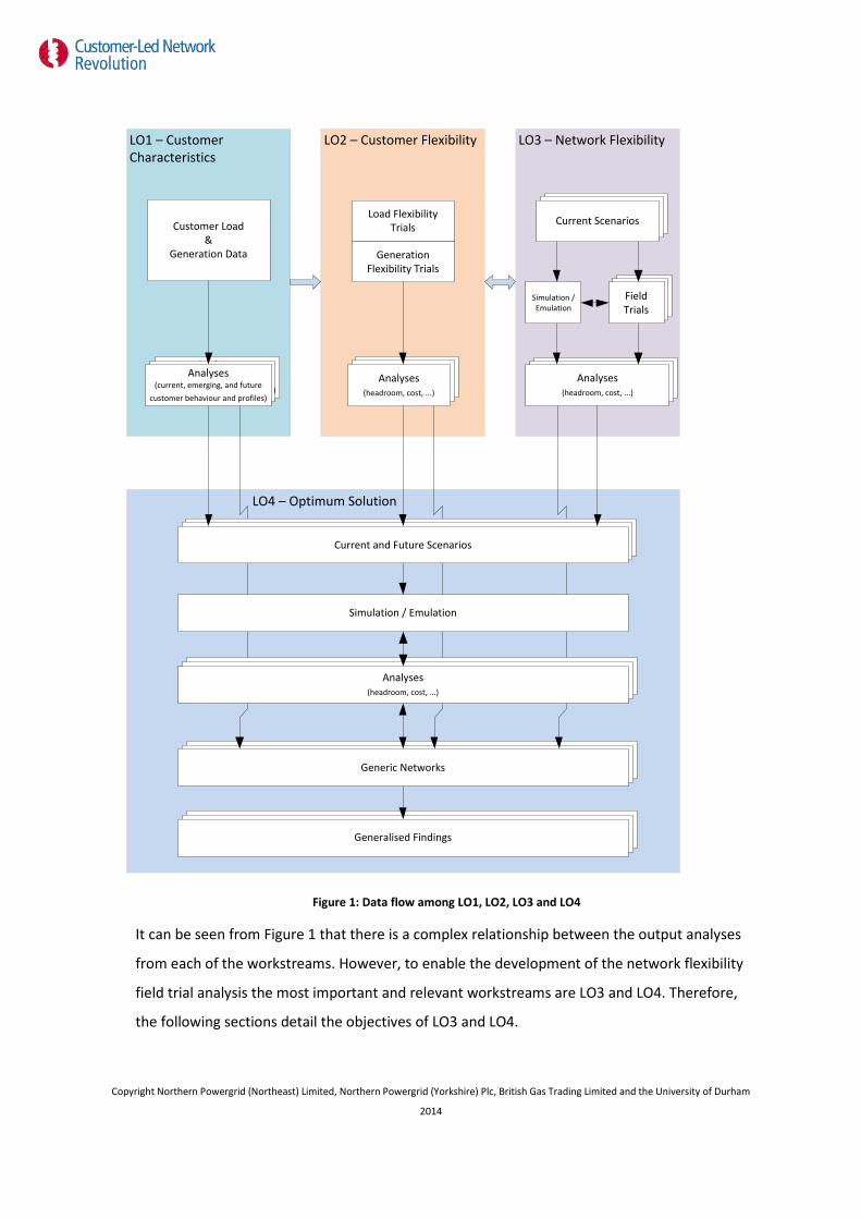
Figure 1: Data flow among LO1, LO2, LO3 and LO4
It can be seen from Figure 1 that there is a complex relationship between the output analyses
from each of the workstreams. However, to enable the development of the network flexibility
field trial analysis the most important and relevant workstreams are LO3 and LO4. Therefore,
the following sections detail the objectives of LO3 and LO4.
LO1 – Customer Characteristics
Analyses (current, emerging, and future
customer behaviour and profiles)
Analyses (current, emerging, and future
customer behaviour and profiles)
LO4 – Optimum Solution
LO3 – Network Flexibility
Field TrialField Trial
Current ScenariosCurrent Scenarios
Generic NetworkGeneric Network
LO2 – Customer Flexibility
HeadroomHeadroom Headroom Headroom
Customer Load&
Generation Data
Analyses (current, emerging, and future
customer behaviour and profiles)
Load Flexibility Trials
Generation Flexibility Trials
Current Scenarios
Simulation / Emulation
Field Trials
Analyses(headroom, cost, ...)
Analyses(headroom, cost, ...)
Headroom Analyses
Generic Networks
Generic NetworkGeneric NetworkGeneralised Findings
Current and Future ScenarioCurrent and Future ScenarioCurrent and Future Scenarios
Simulation / Emulation
Headroom AnalysesHeadroom AnalysesAnalyses(headroom, cost, ...)
Copyright Northern Powergrid (Northeast) Limited, Northern Powergrid (Yorkshire) Plc, British Gas Trading Limited and the University of Durham
2014
2.2 Overview of LO3 objectives
LO3 seeks to investigate the extent to which the network is flexible and the cost of this
flexibility. The overall objective can be subdivided into three sub-objectives:
1. What are the most effective interventions to deliver this flexibility?
2. What is the unit cost of delivering flexibility by each intervention?
3. How is the volume of flexibility and its cost differ by network?
2.3 Overview of LO4 objectives
LO4 seeks to investigate what is the optimum solution to resolve network constraints driven by
the transition to a low carbon economy.
The specific learning outcome sought is optimising the mix of customer and network solutions
by:
1. Constraint types
2. Customer load & generation flexibility and by customer type.
The ultimate goal of the LO4 work is to generalize the learning in terms of network types,
problem types and respective solutions.
2.4 Overview of network flexibility field trials
To enable the investigation of the objectives presented in the previous sections four network
flexibility field trial test cells were designed and developed on four separate areas of the
Northern Powergrid distribution network. A summary of the network flexibility test cells and the
network interventions deployed and to be deployed in each test cell is presented below [1, 2].
• Low density rural 20kV network (Denwick, Northumberland) (Test Cell 21)
o Enhanced Automatic Voltage Control (EAVC) at primary transformers, in-line 20kV
auto-transformer voltage regulators, 20kV/LV secondary substations and for shunt
20kV switched capacitor bank enabled by distributed voltage monitoring;
o Real Time Thermal Ratings (RTTR) technology to be deployed on 66kV OHL, 66/20kV
transformers, 20kV OHL and 20kV/LV transformers;
o Bidirectional electrical energy storage (EES) at secondary substation and towards the
end of feeders.
• High density urban 6kV network (Rise Carr, Darlington) (Test Cell 22) Copyright Northern Powergrid (Northeast) Limited, Northern Powergrid (Yorkshire) Plc, British Gas Trading Limited and the University of Durham
2014

o EAVC at primary transformers and at 6kV/LV secondary substations
o RTTR technology to be deployed on 33kV UGC, 33/6kV transformers , 6kV UGC,
6kV/LV transformers (Dynamic Ratings/MR), LV UGC (EATL instruments)
o Bidirectional EES at primary substation, secondary substation and towards the end
of feeders.
• PV reception networks (Maltby, Rotherham) (Test Cell 23)
o EAVC at secondary transformer
o Bidirectional EES towards the end of feeders
• Heat pump clusters (To be confirmed) (Test Cell 24)
o EAVC at secondary transformer
In addition, to the network interventions the EAVC, RTTR, EES and monitoring systems in each
test cell are integrated using a hierarchical control scheme designated as the Grand Unified
Scheme (GUS) to investigate the synergies associated with the coordinated control of these
network interventions and where possible customer interventions.
Copyright Northern Powergrid (Northeast) Limited, Northern Powergrid (Yorkshire) Plc, British Gas Trading Limited and the University of Durham
2014
3 Trial Analysis Methodology
3.1 Introduction
3.2 Pre-trial Simulation and Emulation
Pre-trial simulation and emulation work is all about providing confidence to field trials. After
developing models of field trial distribution networks and network components, the pre-trial
simulation and emulation work will be carried out to evaluate the network and components at
operational limits in order to build confidence that the deployment of specific field trial
programme will result in the system moving outside the existing operational envelope and
cause disruption to customers. The following details the circumstances where simulation and
emulation is necessary and the specific requirements for simulation and emulation.
3.2.1 Steady-state load flow simulations (IPSA2)
Steady-state load flow simulations (IPSA2) will be required to build confidence that the
distribution network configuration under evaluation, during a specific field trial, will not move
outside the operational envelope of the network. This will be evaluated using relevant
combinations of extreme conditions, such as maximum and minimum load, maximum PV
generation, maximum EES charging and discharging, lowest and highest tap position of tap
transformer, etc. For example, for Rise Carr trial 22.91, Closed loop GUS controlled powerflow
management system with RTTR and voltage control at High Northgate and Harrowgate Hill, the
pre-trial steady-state simulation will evaluate the scenario where the powerflow control
algorithm instructs DSR and EES in Rise Carr, where specific combinations of minimum and
maximum capacity of DSR, minimum and maximum power of charging and discharging of EES
result in the system moving towards the steady-state operational limits of the distribution
network.
These steady-state load flow simulations are required in field trials where the following
interventions or combinations are required to execute a field trial: -
1. EES1, EES2 and EES3
2. GUS control of primary transformer OLTCs
3. GUS control of secondary transformer OLTC
4. GUS control of capacitor bank Copyright Northern Powergrid (Northeast) Limited, Northern Powergrid (Yorkshire) Plc, British Gas Trading Limited and the University of Durham
2014

5. GUS control at HV regulators
It should be noted however that some of these combinations can be evaluated for multiple field
trials with a single simulation run.
Implementation and evaluation of control using low temporal resolution, long time duration (~1
year). This type of analysis will enable evaluation of the following headroom metrics described
earlier in this section:
• Thermal constraints
• Voltage headroom/legroom
• Firm
• Interruptible
• Realisable
• Energy throughput
3.2.2 Dynamic simulation with PSCAD
To evaluate dynamic performance of the networks and the dynamic interaction between
network interventions and control systems during events such as tap changing of OLTC, EES
starting charging or discharging, etc. dynamic simulation is required. Dynamic simulations can
provide confidence that the deployment and integration of network interventions and control
schemes during a specific field trial will not cause instability in the immediate network and/or
other undesirable dynamic phenomenon. These simulations focus on specific dynamic event,
such as an increase in load to maximum, increase in PV generation from zero to maximum, EES
fully charging and switching to fully discharging, multiple tap steps in succession on OLTCs, etc.
which could led to undesirable or unstable network operation.
These dynamic simulations are required in field trials where the following interventions or
combinations are required to execute a field trial: -
1. EES1
2. GUS control of primary transformer OLTCs
3. GUS control of capacitor bank
4. GUS control at HV regulators
It should be noted however that some of these combinations of can be evaluated for multiple
field trials with a single simulation run. Copyright Northern Powergrid (Northeast) Limited, Northern Powergrid (Yorkshire) Plc, British Gas Trading Limited and the University of Durham
2014
Implementation and evaluation of control events using medium temporal resolution, short time
duration (~10 minutes). This type of analysis will enable evaluation of the dynamic operation of
smart grid interventions under high penetrations of LCT which are not possible during the trials
and the practical implications of the control system. In particular, the followings scenarios will
be investigated:
• Winter peak scenario(s) (Denwick, Rise Carr and Hexham)
• Summer peak scenario (s) Maltby
Unbalanced, dynamic models. Previous work in PSCAD used single phase inverter models and
loads to evaluate dynamic control algorithms.
3.2.3 Dynamic emulation with Durham University Smart Grid Laboratory
The Durham University Smart Grid laboratory enables evaluation of the dynamic interaction
between the distribution network and LCTs during events such as tap changing of OLTC, EES
starting charging or discharging, etc. This system can provide confidence that the deployment
and integration of network interventions and control schemes during a specific field trial will
not seriously impact on the operation of LCTs and other loads. These emulations focus on
specific dynamic events similar to those identified for dynamic simulation. Furthermore,
dynamic simulation will enable identification of the events that need to be emulated with this
facility.
Emulations could be required in field trials where the following interventions or combinations
are required to execute a field trial: -
1. EES1
2. GUS control of primary transformer OLTCs
3. GUS control of capacitor bank
4. GUS control at HV regulators
It should be noted however that some of these combinations of can be evaluated for multiple
field trials with a single emulation run.
In addition, the smart grid laboratory is also capable of interfacing with protection and control
relays (SuperTAPP N+), industrial PCs and system controllers using either analogue and digital
I/O and proprietary protocols such as DNP3 and IEC61850. Therefore, the system is capable, if
required, of testing and verifying the operation of Enhanced Network Devices (ENDs) and higher
Copyright Northern Powergrid (Northeast) Limited, Northern Powergrid (Yorkshire) Plc, British Gas Trading Limited and the University of Durham
2014

level control system hardware prior to their deployment in the field trials. This would require
some additional work to achieve this functionality.
3.3 Post-trial Simulation and Emulation
3.3.1 Overview
In order to ensure that the objectives outlined previously are met, a programme of systematic
evaluation of the results from the network flexibility field trials has been developed at Durham
University. This approach is derived from previous experience of trials at Durham University and
from the outline approach referred to previously. In [bid document reference], it is required
that the results from the trials are firstly used to validate the network and network component
models. The results from the trials should then be extrapolated and generalised to ensure that
the results are applicable to 80% of the GB distribution network.
The systematic approach proposed by Durham University consists of five steps: -
1. Validation
2. Extension
3. Extrapolation
4. Enhancement
5. Generalisation
This methodology is designated as VEEEG (Validation, Extension, Extrapolation, Enhancement,
Generalisation) and is illustrated diagrammatically in Figure 2.
Copyright Northern Powergrid (Northeast) Limited, Northern Powergrid (Yorkshire) Plc, British Gas Trading Limited and the University of Durham
2014
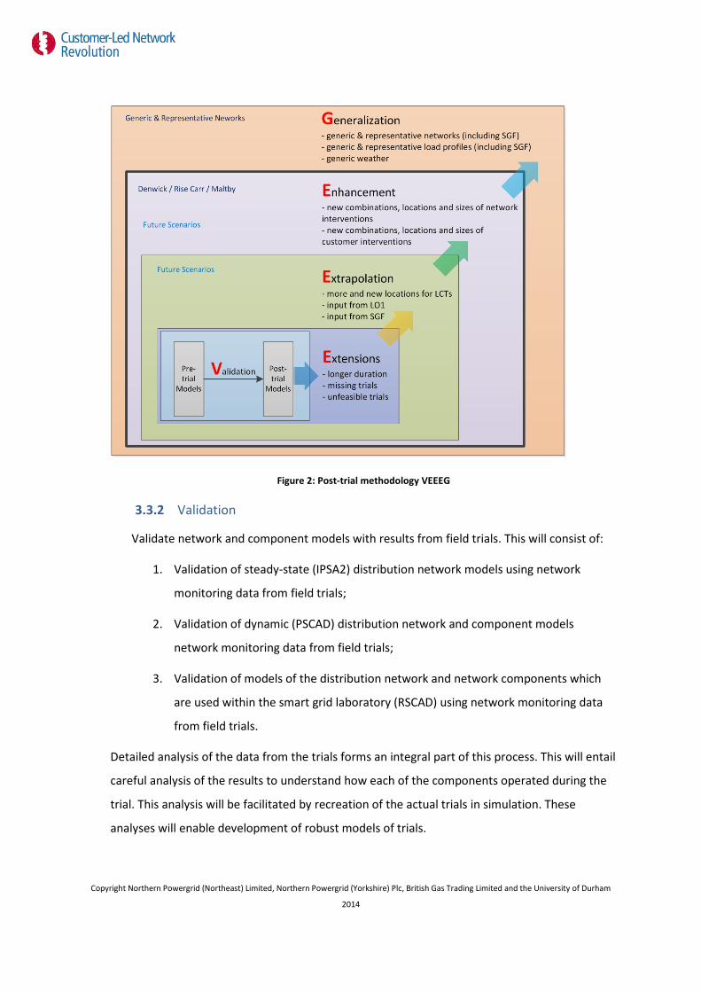
Figure 2: Post-trial methodology VEEEG
3.3.2 Validation
Validate network and component models with results from field trials. This will consist of:
1. Validation of steady-state (IPSA2) distribution network models using network
monitoring data from field trials;
2. Validation of dynamic (PSCAD) distribution network and component models
network monitoring data from field trials;
3. Validation of models of the distribution network and network components which
are used within the smart grid laboratory (RSCAD) using network monitoring data
from field trials.
Detailed analysis of the data from the trials forms an integral part of this process. This will entail
careful analysis of the results to understand how each of the components operated during the
trial. This analysis will be facilitated by recreation of the actual trials in simulation. These
analyses will enable development of robust models of trials.
Copyright Northern Powergrid (Northeast) Limited, Northern Powergrid (Yorkshire) Plc, British Gas Trading Limited and the University of Durham
2014

It should be noted that Durham University have already completed initial validation of the
steady-state network models developed in IPSA2 of Rise Carr, Denwick and Mortimer Road [3-
6]
3.3.3 Extension
Extend field trials by simulating longer duration of trials, simulating/emulating any missing
trials, and simulating/emulating the trials which are not feasible as part of the CLNR network
flexibility field trial programme.
• Field trials that will be carried out during the CLNR network flexibility field trial
programme will be of limited duration. These trials will need to be extended to
evaluate the operation of the field trial over a full year.
• Field trials that were not completed due to operational, planning or logistical
constraints which were due to be completed as per the network flexibility field trial
matrix.
• Unfeasible trials (primarily due to operational reasons)
o Field trials that require an outage of the capacitor bank at Hedgeley Moor;
o Field trials that require the adjustment of the tap position/target voltage of
the primary transformer OLTCs to observe the operation of the distribution
network system operating close to or outside statutory limits;
o Field trials that require N-1 or N-2 conditions to exercise the assets e.g.
normally open points closed and the majority of the demand is fed from
Darlington [7];
o EES1 operation near the statutory voltage and thermal limits of the system.
Evaluating salient unavailable network flexibility field trials in simulation will enable evaluation
of the impacts of different combinations of network intervention and control schemes on
headroom. As a consequence, this will also enable the evaluation of the cost/kW for each
network intervention cognisant of the network constraint under consideration.
A multi-step load flow approach using half-hourly data is seen to be appropriate in most cases
to investigate these characteristics. Where concerns exist with regard to the operation of a
distribution network system under a particular control scheme and network interventions,
Copyright Northern Powergrid (Northeast) Limited, Northern Powergrid (Yorkshire) Plc, British Gas Trading Limited and the University of Durham
2014

dynamic simulations based on previously validated network models and network components
will be used to investigate the feasibility of the operation of the proposed system.
Initial planning
• Longer duration: run one year SCADA data with IPSA2.
• Unfeasible trials: lock out capacitor bank, extra smart grid interventions without
supervisory control (distributed control approach)
3.3.4 Extrapolation
Extrapolate the results of the network flexibility field trials by moving the locations and
increasing the penetrations of LCTs, to evaluate the headroom for future scenarios of the trial
networks. The profiles used for the future scenarios are informed by results of the analysis in
LO1 (load profile) and the Smart Grid Forum [8]. For example, in trial extrapolation work the
current percentage of PV installation in Maltby network was increased to 60% which resulted in
a voltage violation of the upper statutory voltage limit [9]. In addition, we will look at relocating
LCT when they do not already exist at these locations on a network. In order to simulate this
future scenario, which is unfeasible in the trials, in [3], a 60% penetration of PV was added to
the end of the longest feeder of Maltby network. By increasing the penetration of PV and
moving the locations of distributed PV to a centralised location at the end of the feeder, this
extrapolation will enable the exploration of the impacts of high penetration of PV on the
network voltage.
Evolving load and generation patterns and LCT penetration growth will impact on headroom in
distribution networks and determines the optimal choices of network combinations.
As previously, a multi-step load flow approach using half-hourly data is seen to be appropriate
in most cases to investigate these characteristics. As these scenarios require the system to be
operating closer to the limits of the operational envelope, dynamic simulation and emulation of
events informed by the multi-step load flow results will be useful to establish the performance
of the network interventions and control schemes.
Initial planning
• More LCTs: increasing the penetrations of PV, EV and HP until voltage violations occur on the network
• New locations of LCTs: evenly distributed and clustered, six different scenarios
Copyright Northern Powergrid (Northeast) Limited, Northern Powergrid (Yorkshire) Plc, British Gas Trading Limited and the University of Durham
2014
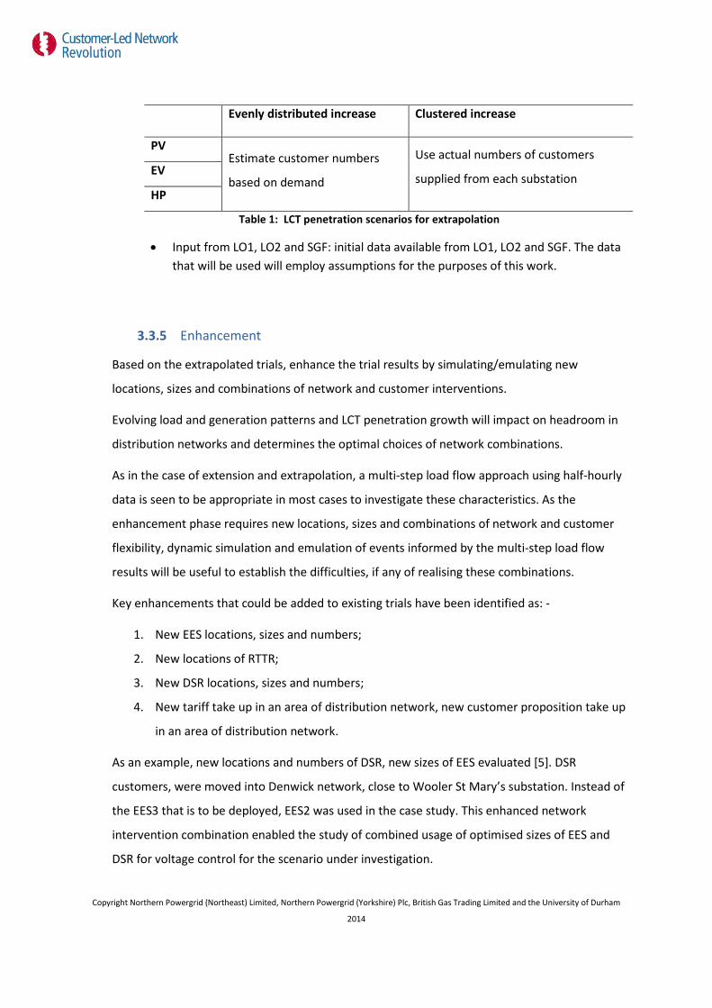
Evenly distributed increase Clustered increase
PV Estimate customer numbers
based on demand
Use actual numbers of customers
supplied from each substation EV
HP
Table 1: LCT penetration scenarios for extrapolation
• Input from LO1, LO2 and SGF: initial data available from LO1, LO2 and SGF. The data that will be used will employ assumptions for the purposes of this work.
3.3.5 Enhancement
Based on the extrapolated trials, enhance the trial results by simulating/emulating new
locations, sizes and combinations of network and customer interventions.
Evolving load and generation patterns and LCT penetration growth will impact on headroom in
distribution networks and determines the optimal choices of network combinations.
As in the case of extension and extrapolation, a multi-step load flow approach using half-hourly
data is seen to be appropriate in most cases to investigate these characteristics. As the
enhancement phase requires new locations, sizes and combinations of network and customer
flexibility, dynamic simulation and emulation of events informed by the multi-step load flow
results will be useful to establish the difficulties, if any of realising these combinations.
Key enhancements that could be added to existing trials have been identified as: -
1. New EES locations, sizes and numbers;
2. New locations of RTTR;
3. New DSR locations, sizes and numbers;
4. New tariff take up in an area of distribution network, new customer proposition take up
in an area of distribution network.
As an example, new locations and numbers of DSR, new sizes of EES evaluated [5]. DSR
customers, were moved into Denwick network, close to Wooler St Mary’s substation. Instead of
the EES3 that is to be deployed, EES2 was used in the case study. This enhanced network
intervention combination enabled the study of combined usage of optimised sizes of EES and
DSR for voltage control for the scenario under investigation.
Copyright Northern Powergrid (Northeast) Limited, Northern Powergrid (Yorkshire) Plc, British Gas Trading Limited and the University of Durham
2014
3.3.6 Generalization
Generalize the results from the four trial networks, collect most valuable learning.
As the test cells have been designed to represent rural and urban networks generalisation is
already implicit in the overall analysis. This is reinforced by the systematic design of the trials
which ensures that the field trials that are carried out on the urban and rural networks often
have elements in common. In addition, generic networks, which will be informed by the smart
grid forum work and from previous research at Durham will be developed, the load and
generation profiles will be informed by the extrapolation phases, and enhanced by the addition
of network and customer interventions. Therefore, it can be seen that this phase also requires
elements of the previous two phases (extrapolation and enhancement) to be implemented on
the final generic networks to investigate the cumulative effects of load and generation change,
the possibility of customer flexibility and network flexibility.
Furthermore, to generalise the results further, generic load and generation data and weather
data will be implemented on the test cell models.
3.4 Post simulation analysis and reporting
The final output from the trial analysis work at Durham University will be a group of reports that
evaluate, using results from the VEEEG, analysis methodology, solutions and groups of solutions
using the evaluation criteria detailed in the following sections. Included in these reports will be
a merit order of solutions, by constraint type.
3.4.1 Evaluation criteria
These are as follows: -
• Headroom
• Ensure system operates within network constraints;
• Resilience and reliability;
• Scalability and flexibility;
• Communications requirements;
• Network losses;
• Cost and complexity
Copyright Northern Powergrid (Northeast) Limited, Northern Powergrid (Yorkshire) Plc, British Gas Trading Limited and the University of Durham
2014

Previous work has identified a number of other metrics and evaluation criteria for evaluating
active networks/smart grids. Much of the previous work has focussed on overcoming the
technical obstacles to the integration of microgeneration and DG into distribution networks
using active networks/smart grids instead of network reinforcement. The CLNR project has
somewhat broader objectives as it focuses on load as well as generation, in the form of large
penetrations of LCTs in the distribution network. This focus however does not change the
technical issues associated with future distribution networks which will need to cater for larger
current flows and changes to the traditional flow of power due to the predicted electrification
of transport and heat and the mass deployment of microgeneration in distribution networks
[10, 11].
The deployment of network interventions operating as part of an integrated overall network
management system, to enable greater network flexibility, results in greater observability and
integrated controllability. These increases in observability and controllability enable
maximisation of the utilisation of the distribution network assets under the supervision of the
power flow control. This gives the distribution network, under consideration, the capability to
integrate higher levels of LCTs without requiring conventional, “copper intensive”, heavy
distribution network upgrades.
As per the bid document, this network flexibility consists of two components:
1. Background flexibility, invisible to the customer; and
2. Identification of interruptible capacity that can be offered to customers, with means to
interrupt that capacity as required. This last overlaps with customer flexibility, as
interruptible contracts for non-firm network capacity are valuable only to customers
with flexible demand.
Cognisant of these issues the following evaluation criteria are proposed: -
3.4.2 Headroom
It has been recognised in the bid document that the most important evaluation criterion of
network flexibility is headroom as this enables comparison with network reinforcement
approaches to integration of large penetrations of LCT.
The primary requirement of the field trials is to enable investigation of the availability of
network flexibility and how much it will cost. The result of this investigation will be to enable
comparison of novel and conventional network solutions to increasing integration of LCTs. In Copyright Northern Powergrid (Northeast) Limited, Northern Powergrid (Yorkshire) Plc, British Gas Trading Limited and the University of Durham
2014
this work, headroom is defined as the capacity of the distribution network to integrate greater
penetrations of LCTs.
Currently, the relationship between supply and demand in a conventional distribution network
is relatively simple. The demand in a distribution network is not generally controllable but can
be predicted in terms of peak and minimum load with reasonable accuracy. Supply to the
network is planned to meet the demand within defined limits. Therefore, the definition of
headroom is informed by worst case scenario type planning limits and is defined as the
additional demand/generation capacity that can be accepted on the existing system expressed
in MW.
In flexible distribution networks, the relationship between supply and demand distribution
network is more complicated. In this scenario, DSP, EES, EAVC and RTTR provide extra flexibility
which can be utilised to integrate larger amounts of LCTs. In this scenario, the relationship
between supply and demand is more fluid and is dictated by the state of the distribution
network system at a particular point in time. Therefore, the headroom in this case is informed
by a combination of: -
• More accurate planning limits, informed by the extra information available about the
state of the network
• Operational limits which are dependent on the instantaneous state of the network
Previous work completed by a consortium of UK DNOs and industry on behalf of OFGEM has
sought to define a number of definitions of headroom as follows [12]: -
Thermal constraints
Thermal Conductor: The percentage of thermal constraint on a circuit (overhead line or
underground cable) released. A positive figure would represent an increase in the headroom on
circuit capacity on the base-case (e.g. a dynamic line rating solution increasing a line rating from
100% to 130% is captured as 30%).
Thermal Transformer: Percentage of thermal constraint of transformer released. A positive
figure would represent an increase on the current base-case (e.g. a dynamic transformer rating
solution increasing an asset rating from 100% to 120% is captured as 20%). Where: LV =
Distribution (HV/LV) Transformer; HV = Primary (EHV/HV) Transformer; EHV = Grid (SGT/EHV)
Transformer.
Copyright Northern Powergrid (Northeast) Limited, Northern Powergrid (Yorkshire) Plc, British Gas Trading Limited and the University of Durham
2014

Voltage constraints
Voltage Headroom
Percentage of voltage headroom released. Voltage headroom starting position is based on the
difference between the (line) voltage at the transformer infeed and the upper statutory limit.
• LV – starting position = 1.5% headroom (difference between 433V and the upper
statutory limit of 440V)
• HV, e.g. 11kV – starting position = 6% headroom (as most Primary transformers have
tap changers and can optimize voltages in line with Statutory limits)
• EHV , e.g. 33kV or 132kV - starting position = 10% headroom (as most Grid transformers
have tap changers and can optimize voltages in line with Statutory limits)
An increase in headroom is therefore associated with a reduction in volts on the circuit or at the
transformer infeed. A three-phase inline LV voltage regulator with an operating bandwidth of
±20V is captured as giving 5% voltage headroom.
Voltage Legroom
Percentage of voltage legroom released. Voltage legroom starting position is based on the
difference between the (line) voltage at the end of a feeder and the lower statutory limit.
• LV – starting position = 14.5% legroom (difference between the voltage at the busbars
(433V) and the lower statutory limit of 376V)
• HV, e.g. 11kV – starting position = 6% legroom (as most Primary transformers have tap
changers and can optimize voltages in line with Statutory limits)
• EHV , e.g. 33kV or 132kV - starting position = 10% legroom (as most Grid transformers
have tap changers and can optimize voltages in line with Statutory limits)
An increase in legroom is therefore associated with an increase in volts on the circuit or at the
transformer infeed. A three-phase inline LV voltage regulator with an operating bandwidth of
±20V is captured as giving 5% voltage legroom.
In this work, it is proposed to extend these definitions of headroom further to reflect the more
complex relationship between supply and demand in these networks: -
Copyright Northern Powergrid (Northeast) Limited, Northern Powergrid (Yorkshire) Plc, British Gas Trading Limited and the University of Durham
2014

1. Firm headroom – Headroom available that is available to load or generation that cannot
be interrupted. This is similar to the single definition of headroom for existing networks,
although with better information on worst case demand and supply
2. Interruptible headroom (peak) – Peak headroom available to load or generation that
can be interrupted or is facilitated by time limited load or generation
3. Energy consumption/export – Maximum energy throughput consumption/export
through system . This is important as it is an indicator of the uplift in energy delivered
to the network. This is an important metric when considering interruptible of managed
load or generation.
4. Realisable headroom (probabilistic) – There are uncertainties associated with
participation percentage of DSP, the ratings delivered by RTTR, the output of
intermittent generation and load. Therefore, in a network scenario with DSP, RTTR and
intermittent local generation there will be some uncertainty as to what headroom is
available. It is therefore unlikely that the full interruptible headroom can be realised in
practice. However, it is possible to quantify the probabilities associated with these
systems and thus assess the probability of realising a proportion of the peak
interruptible headroom. Therefore, as we increase the degree of certainty required the
realisable headroom figure will tend to reduce. Conversely, if we reduce the degree of
certainty required the realisable headroom figure is increased. This quantity will
therefore be defined as the realisable headroom available accompanied by an
associated degree of certainty.
However, the exact capability of a distribution network, with integrated network interventions
deployed, to integrate LCTs is dependent on: -
1. Portfolio of LCT under consideration and their consumption profiles
2. Distribution of the LCTs on the network
3. Network topology
4. Profiles and distribution of the loads across the system
5. Profiles and distribution of the generation across the system
3.4.3 Ensure system operates within network constraints
A number of technical constraints have been identified when large quantities of
microgeneration or other LCTs are deployed on a distribution network. The network constraints
that are focussed on in the CLNR project are: - Copyright Northern Powergrid (Northeast) Limited, Northern Powergrid (Yorkshire) Plc, British Gas Trading Limited and the University of Durham
2014
• Steady-state voltage outside statutory limits.
• Power quality (flicker and harmonics) outside acceptable limits (e.g. ER G5 and P28)
• Operating distribution network circuits above their thermal limits and reverse power
flow.
• Steady-state voltage unbalance moving outside acceptable limits (e.g. ER P29).
3.4.4 Resilience and reliability
The failure or erroneous operation of a component or a software error can also affect the
operation or may result in the complete failure of a control system of an actively managed
network. The resilience to faults and the reliability of the system should therefore be
considered [10, 13].
3.4.5 Scalability and flexibility
As the addition of additional controllable entities are likely to be incremental in nature it is
desirable that the control system architecture is capable of easily integrating extra DG, energy
storage or controllable load. An ideal system would be open and infinitely scalable and flexible
so that the connection of additional devices would require minimal manual modifications. This
is known as “plug and play” capability [10, 13].
3.4.6 Communications requirements
It is desirable that the burden on communications is minimised to reduce costs, facilitate using
existing infrastructure and adds generality to the network solution.
3.4.7 Network losses
The new network interventions and control should seek to minimise the losses seen
within the distribution network.
3.4.8 Cost and complexity
The final criteria to be investigated when evaluating control system architectures and network
interventions is the complexity and the cost of deploying the control system. Costs increase
with the addition of communications infrastructure, data acquisition and controller hosting
Copyright Northern Powergrid (Northeast) Limited, Northern Powergrid (Yorkshire) Plc, British Gas Trading Limited and the University of Durham
2014

hardware. Moreover, if bespoke software solutions are required to realise each system is it
likely that the solution may not be economically viable.
Copyright Northern Powergrid (Northeast) Limited, Northern Powergrid (Yorkshire) Plc, British Gas Trading Limited and the University of Durham
2014
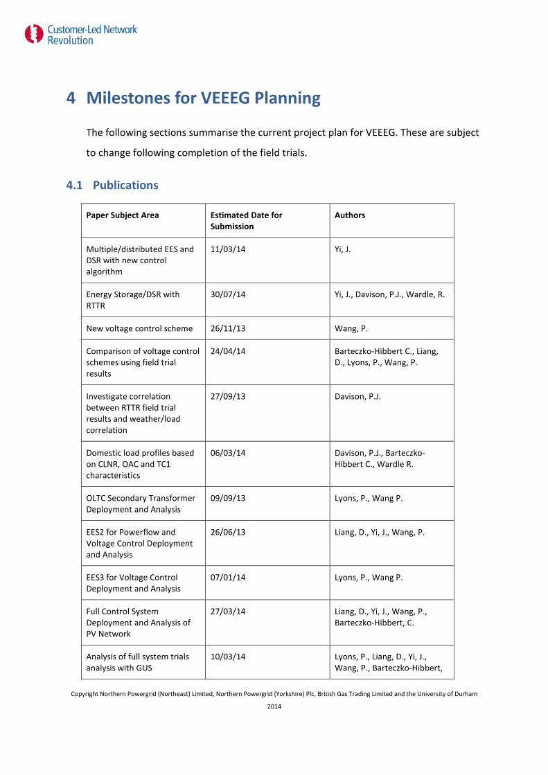
4 Milestones for VEEEG Planning
The following sections summarise the current project plan for VEEEG. These are subject
to change following completion of the field trials.
4.1 Publications
Paper Subject Area Estimated Date for Submission
Authors
Multiple/distributed EES and DSR with new control algorithm
11/03/14 Yi, J.
Energy Storage/DSR with RTTR
30/07/14 Yi, J., Davison, P.J., Wardle, R.
New voltage control scheme 26/11/13 Wang, P.
Comparison of voltage control schemes using field trial results
24/04/14 Barteczko-Hibbert C., Liang, D., Lyons, P., Wang, P.
Investigate correlation between RTTR field trial results and weather/load correlation
27/09/13 Davison, P.J.
Domestic load profiles based on CLNR, OAC and TC1 characteristics
06/03/14 Davison, P.J., Barteczko-Hibbert C., Wardle R.
OLTC Secondary Transformer Deployment and Analysis
09/09/13 Lyons, P., Wang P.
EES2 for Powerflow and Voltage Control Deployment and Analysis
26/06/13 Liang, D., Yi, J., Wang, P.
EES3 for Voltage Control Deployment and Analysis
07/01/14 Lyons, P., Wang P.
Full Control System Deployment and Analysis of PV Network
27/03/14 Liang, D., Yi, J., Wang, P., Barteczko-Hibbert, C.
Analysis of full system trials analysis with GUS
10/03/14 Lyons, P., Liang, D., Yi, J., Wang, P., Barteczko-Hibbert,
Copyright Northern Powergrid (Northeast) Limited, Northern Powergrid (Yorkshire) Plc, British Gas Trading Limited and the University of Durham
2014
C.
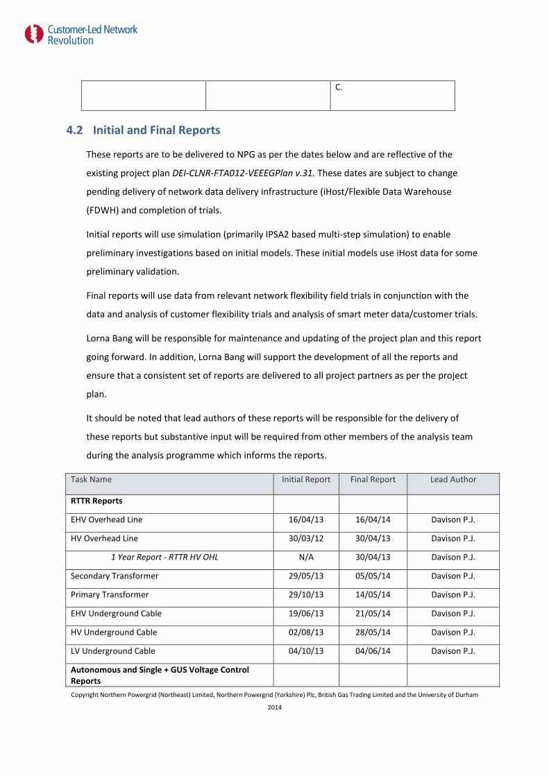
4.2 Initial and Final Reports
These reports are to be delivered to NPG as per the dates below and are reflective of the
existing project plan DEI-CLNR-FTA012-VEEEGPlan v.31. These dates are subject to change
pending delivery of network data delivery infrastructure (iHost/Flexible Data Warehouse
(FDWH) and completion of trials.
Initial reports will use simulation (primarily IPSA2 based multi-step simulation) to enable
preliminary investigations based on initial models. These initial models use iHost data for some
preliminary validation.
Final reports will use data from relevant network flexibility field trials in conjunction with the
data and analysis of customer flexibility trials and analysis of smart meter data/customer trials.
Lorna Bang will be responsible for maintenance and updating of the project plan and this report
going forward. In addition, Lorna Bang will support the development of all the reports and
ensure that a consistent set of reports are delivered to all project partners as per the project
plan.
It should be noted that lead authors of these reports will be responsible for the delivery of
these reports but substantive input will be required from other members of the analysis team
during the analysis programme which informs the reports.
Task Name Initial Report Final Report Lead Author
RTTR Reports
EHV Overhead Line 16/04/13 16/04/14 Davison P.J.
HV Overhead Line 30/03/12 30/04/13 Davison P.J.
1 Year Report - RTTR HV OHL N/A 30/04/13 Davison P.J.
Secondary Transformer 29/05/13 05/05/14 Davison P.J.
Primary Transformer 29/10/13 14/05/14 Davison P.J.
EHV Underground Cable 19/06/13 21/05/14 Davison P.J.
HV Underground Cable 02/08/13 28/05/14 Davison P.J.
LV Underground Cable 04/10/13 04/06/14 Davison P.J.
Autonomous and Single + GUS Voltage Control Reports
Copyright Northern Powergrid (Northeast) Limited, Northern Powergrid (Yorkshire) Plc, British Gas Trading Limited and the University of Durham
2014

Task Name Initial Report Final Report Lead Author
Secondary Transformer Voltage Control 17/06/13 18/06/14 Lyons P.
EES3 Voltage Control Trials 19/07/13 25/06/14 Lyons P.
EES2 Voltage Control Trials 13/05/13 22/04/14 Liang D.
EES1 Voltage Control Trials 17/07/13 29/04/14 Yi J.
Primary Transformer under GUS Control 09/08/13 01/07/14 Lyons P.
Secondary Transformer under GUS Control 16/09/13 07/07/14 Lyons P.
EES3 GUS Voltage Control Trials 11/11/13 16/07/14 Lyons P.
EES2 GUS Voltage Control Trials 05/07/13 01/05/14 Liang D.
EES1 Voltage Control Trials 19/08/13 06/05/14 Yi J.
DSR Voltage Control Trials 21/01/14 23/07/14 Lyons P.
HV Regulator Voltage Control Trials 26/06/13 23/04/14 Wang P.
Capacitor Bank Voltage Control Trials 23/07/13 30/04/14 Wang P.
Collaborative Voltage Control Reports
LV Voltage Control Trials 01/10/13 07/05/14 Wang P.
EES2/DSR Voltage Control Trials 07/08/13 08/05/14 Liang D.
Denwick Collaborative VC N/A 21/05/14 Wang P.
Rise Carr Collaborative VC N/A 04/06/14 Wang P.
Autonomous and Single + GUS Powerflow Management Control Reports
EES3 Powerflow Control Trials 04/09/13 15/05/14 Liang D.
EES2 Powerflow Control Trials 15/04/13 22/05/14 Liang D.
EES1 Powerflow Control Trials 23/09/13 02/06/14 Yi J.
EES3 GUS Powerflow Control Trials 11/10/13 30/05/14 Liang D.
EES2 GUS Powerflow Control Trials 25/11/13 06/06/14 Liang D.
EES1 GUS Powerflow Control Trials 31/10/13 12/06/14 Yi J.
DSR Powerflow Control Trials 13/12/13 20/06/14 Yi J.
Collaborative Powerflow Management Reports
LV Feeder Powerflow Control 17/01/14 05/08/14 Liang D.
Secondary Transformer Powerflow Control 24/02/14 17/09/14 Liang D.
Full System Report N/A 03/09/14 Lyons P.
Copyright Northern Powergrid (Northeast) Limited, Northern Powergrid (Yorkshire) Plc, British Gas Trading Limited and the University of Durham
2014
5 Pre-trial simulation and VEEEG work Specific pre-trial simulations are required for some of the trials to enable NPG to build
confidence in the deployment of the trials.. Where possible this will also overlap with VEEEG
work to ensure maximum efficiency and impact of any simulation work that is completed as
part of CLNR. Where possible simulation work should be carried out using IPSA2 as this
approach is likely to produce results for VEEEG efficiently. Use of dynamic and RTDS based
simulation should be carefully evaluated but is useful for the development and evaluation of
control algorithms which can be outside of the delivery criteria for CLNR but is aligned with
academic requirements.
Copyright Northern Powergrid (Northeast) Limited, Northern Powergrid (Yorkshire) Plc, British Gas Trading Limited and the University of Durham
2014
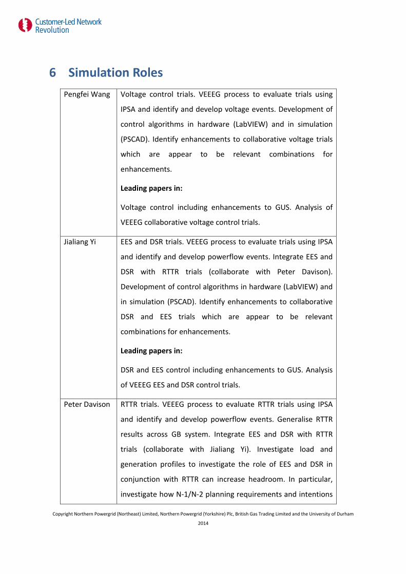
6 Simulation Roles Pengfei Wang Voltage control trials. VEEEG process to evaluate trials using
IPSA and identify and develop voltage events. Development of
control algorithms in hardware (LabVIEW) and in simulation
(PSCAD). Identify enhancements to collaborative voltage trials
which are appear to be relevant combinations for
enhancements.
Leading papers in:
Voltage control including enhancements to GUS. Analysis of
VEEEG collaborative voltage control trials.
Jialiang Yi EES and DSR trials. VEEEG process to evaluate trials using IPSA
and identify and develop powerflow events. Integrate EES and
DSR with RTTR trials (collaborate with Peter Davison).
Development of control algorithms in hardware (LabVIEW) and
in simulation (PSCAD). Identify enhancements to collaborative
DSR and EES trials which are appear to be relevant
combinations for enhancements.
Leading papers in:
DSR and EES control including enhancements to GUS. Analysis
of VEEEG EES and DSR control trials.
Peter Davison RTTR trials. VEEEG process to evaluate RTTR trials using IPSA
and identify and develop powerflow events. Generalise RTTR
results across GB system. Integrate EES and DSR with RTTR
trials (collaborate with Jialiang Yi). Investigate load and
generation profiles to investigate the role of EES and DSR in
conjunction with RTTR can increase headroom. In particular,
investigate how N-1/N-2 planning requirements and intentions
Copyright Northern Powergrid (Northeast) Limited, Northern Powergrid (Yorkshire) Plc, British Gas Trading Limited and the University of Durham
2014
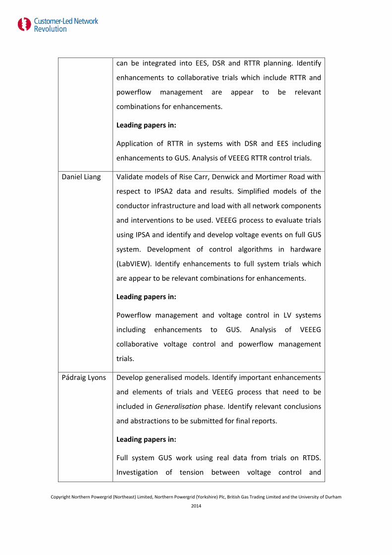
can be integrated into EES, DSR and RTTR planning. Identify
enhancements to collaborative trials which include RTTR and
powerflow management are appear to be relevant
combinations for enhancements.
Leading papers in:
Application of RTTR in systems with DSR and EES including
enhancements to GUS. Analysis of VEEEG RTTR control trials.
Daniel Liang Validate models of Rise Carr, Denwick and Mortimer Road with
respect to IPSA2 data and results. Simplified models of the
conductor infrastructure and load with all network components
and interventions to be used. VEEEG process to evaluate trials
using IPSA and identify and develop voltage events on full GUS
system. Development of control algorithms in hardware
(LabVIEW). Identify enhancements to full system trials which
are appear to be relevant combinations for enhancements.
Leading papers in:
Powerflow management and voltage control in LV systems
including enhancements to GUS. Analysis of VEEEG
collaborative voltage control and powerflow management
trials.
Pádraig Lyons Develop generalised models. Identify important enhancements
and elements of trials and VEEEG process that need to be
included in Generalisation phase. Identify relevant conclusions
and abstractions to be submitted for final reports.
Leading papers in:
Full system GUS work using real data from trials on RTDS.
Investigation of tension between voltage control and
Copyright Northern Powergrid (Northeast) Limited, Northern Powergrid (Yorkshire) Plc, British Gas Trading Limited and the University of Durham
2014

powerflow control where applicable.
Copyright Northern Powergrid (Northeast) Limited, Northern Powergrid (Yorkshire) Plc, British Gas Trading Limited and the University of Durham
2014

7 Long-term VEEEG planning
In the VEEEG work the following assumptions are made with regard to the roles of each analysis
tools:
7.1.1 Steady state analysis (IPSA2)
Implementation and evaluation of control using low temporal resolution, long time duration (~1
year). This type of analysis will enable evaluation of the following headroom metrics described
earlier in this section:
• Thermal constraints
• Voltage headroom/legroom
• Firm
• Interruptible
• Realisable
• Energy throughput
7.1.2 Dynamic analysis (PSCAD)
Implementation and evaluation of control events using medium temporal resolution, short time
duration (~10 minutes). This type of analysis will enable evaluation of the dynamic operation of
smart grid interventions under high penetrations of LCT which are not possible during the trials
and the practical implications of the control system. In particular, the followings scenarios will
be investigated:
• Winter peak scenario(s) (Denwick, Rise Carr and Hexham)
• Summer peak scenario (s) Maltby
Unbalanced, dynamic models. Previous work in PSCAD used single phase inverter models and
loads to evaluate dynamic control algorithms....
7.1.3 Real-Time Emulation (RSCAD and RTDS)
Implementation and evaluation of control events using high temporal resolution, short time
duration (~5 minutes). This type of analysis will enable evaluation of the dynamic operation and
interaction of LCTs and smart grid control interventions which are not possible during the trials
Copyright Northern Powergrid (Northeast) Limited, Northern Powergrid (Yorkshire) Plc, British Gas Trading Limited and the University of Durham
2014

and the impact of control interventions on the operation of the system. In particular, the
followings scenarios will be investigated:
• Winter peak scenario(s) (Denwick, Rise Carr and Hexham)
• Summer peak scenario (s) Maltby
Copyright Northern Powergrid (Northeast) Limited, Northern Powergrid (Yorkshire) Plc, British Gas Trading Limited and the University of Durham
2014
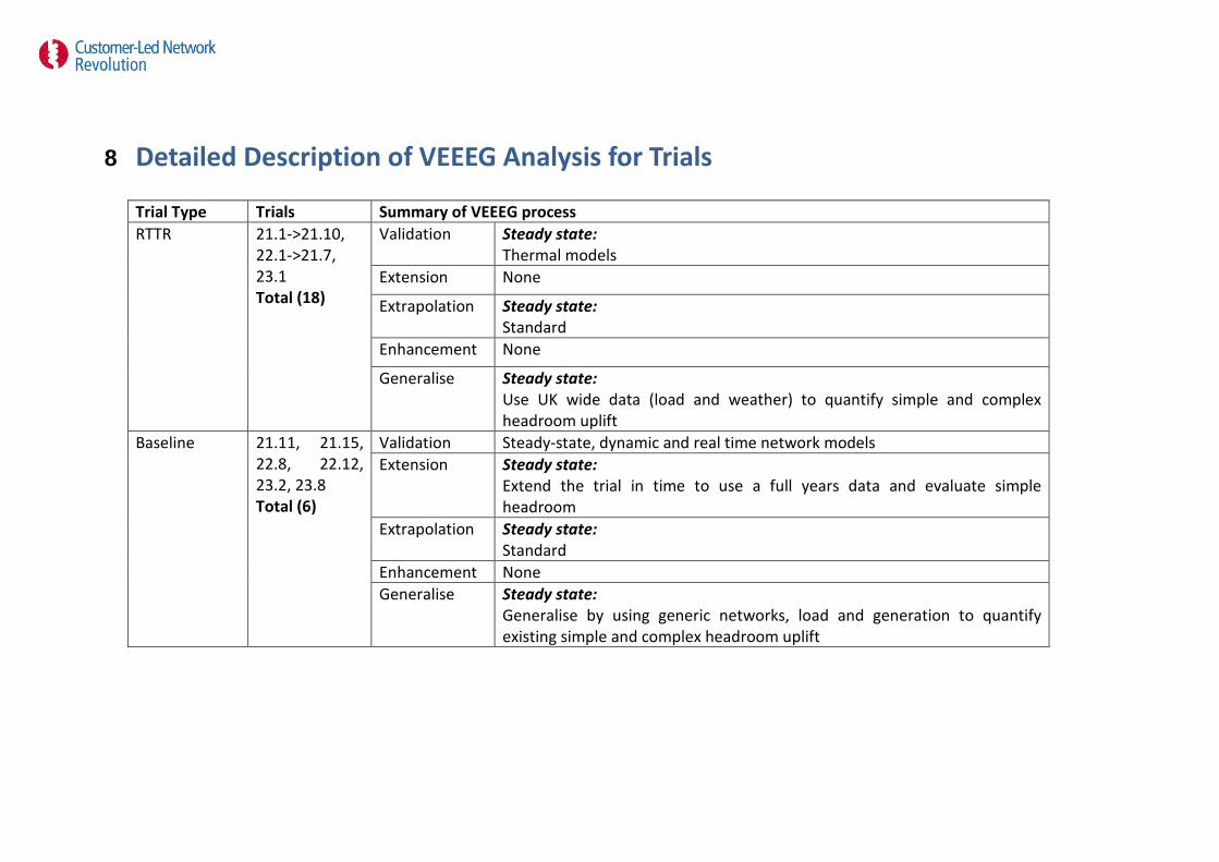
8 Detailed Description of VEEEG Analysis for Trials
Trial Type Trials Summary of VEEEG process RTTR 21.1->21.10,
22.1->21.7, 23.1 Total (18)
Validation Steady state: Thermal models
Extension None
Extrapolation Steady state: Standard
Enhancement None
Generalise Steady state: Use UK wide data (load and weather) to quantify simple and complex headroom uplift
Baseline 21.11, 21.15, 22.8, 22.12, 23.2, 23.8 Total (6)
Validation Steady-state, dynamic and real time network models Extension Steady state:
Extend the trial in time to use a full years data and evaluate simple headroom
Extrapolation Steady state: Standard
Enhancement None Generalise Steady state:
Generalise by using generic networks, load and generation to quantify existing simple and complex headroom uplift

Autonomous voltage control
21.13, 21.17, 21.19->21.22, 22.10, 22.14->22.23, 23.3, 23.6, 23.8, 23.9 Total (20)
Validation Steady-state, dynamic and real time network models Extension Steady state:
Extend the trial in time to use a full years data and evaluate simple headroom
Extrapolation Steady state: Standard (Implementation and evaluation of control) Dynamic: Winter peak scenario(s) (Denwick, Rise Carr and Hexham); Summer peak scenario (s) Maltby (Implementation and evaluation of control) Real-Time Emulation: Winter peak scenario(s) (Denwick, Rise Carr and Hexham); Summer peak scenario (s) Maltby (Evaluation of control events)
Enhancement Steady state: EES1: Change in power rating of unit (1.25MVA, 5MVA, 10MVA). New locations: (Hedgeley Moor, Harrogate Hill North, TBC) EES2: Change in power rating of unit (50kVA, 200kVA, 400kVA) EES3: Change in power rating of unit (25kVA, 100kVA, 200kVA). Optimised location on feeder. EES3 units on all feeders. Capacitor banks locked out HV regulators locked out Dynamic: EES1: Change in power rating of unit (10MVA). New locations: (Hedgeley Moor, Harrogate Hill North, TBC) EES2: Change in power rating of unit (400kVA) EES3: Change in power rating of unit (200kVA). EES3 units on all feeders. Reduce time delay across smart grid Real-Time Emulation: EES1: Change in power rating of unit (10MVA). New locations: (Hedgeley
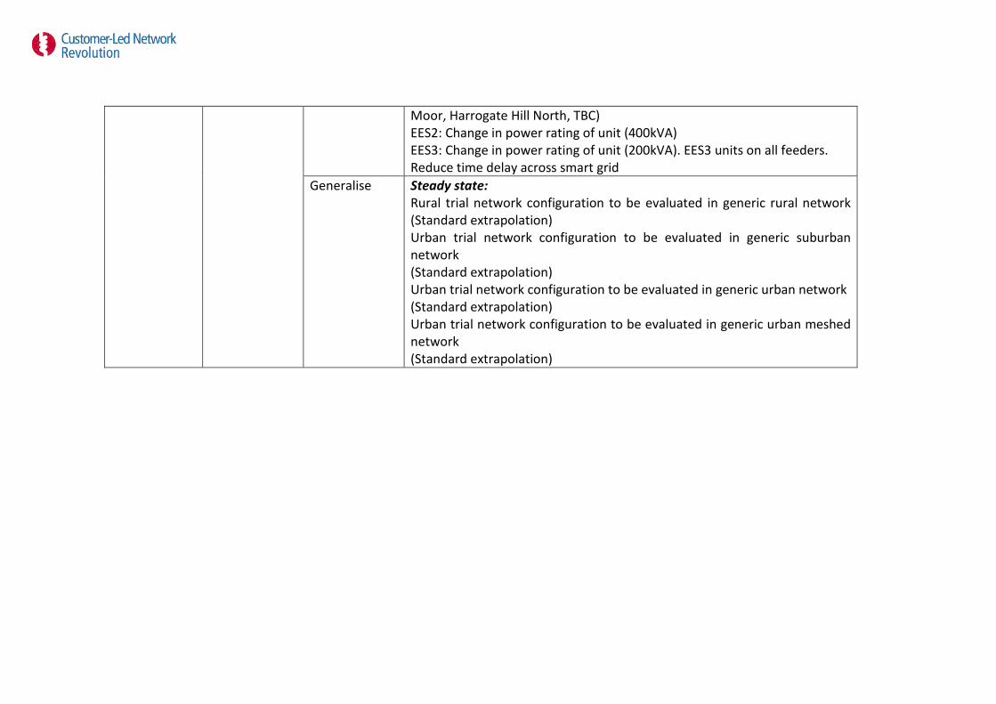
Moor, Harrogate Hill North, TBC) EES2: Change in power rating of unit (400kVA) EES3: Change in power rating of unit (200kVA). EES3 units on all feeders. Reduce time delay across smart grid
Generalise Steady state: Rural trial network configuration to be evaluated in generic rural network (Standard extrapolation) Urban trial network configuration to be evaluated in generic suburban network (Standard extrapolation) Urban trial network configuration to be evaluated in generic urban network (Standard extrapolation) Urban trial network configuration to be evaluated in generic urban meshed network (Standard extrapolation)
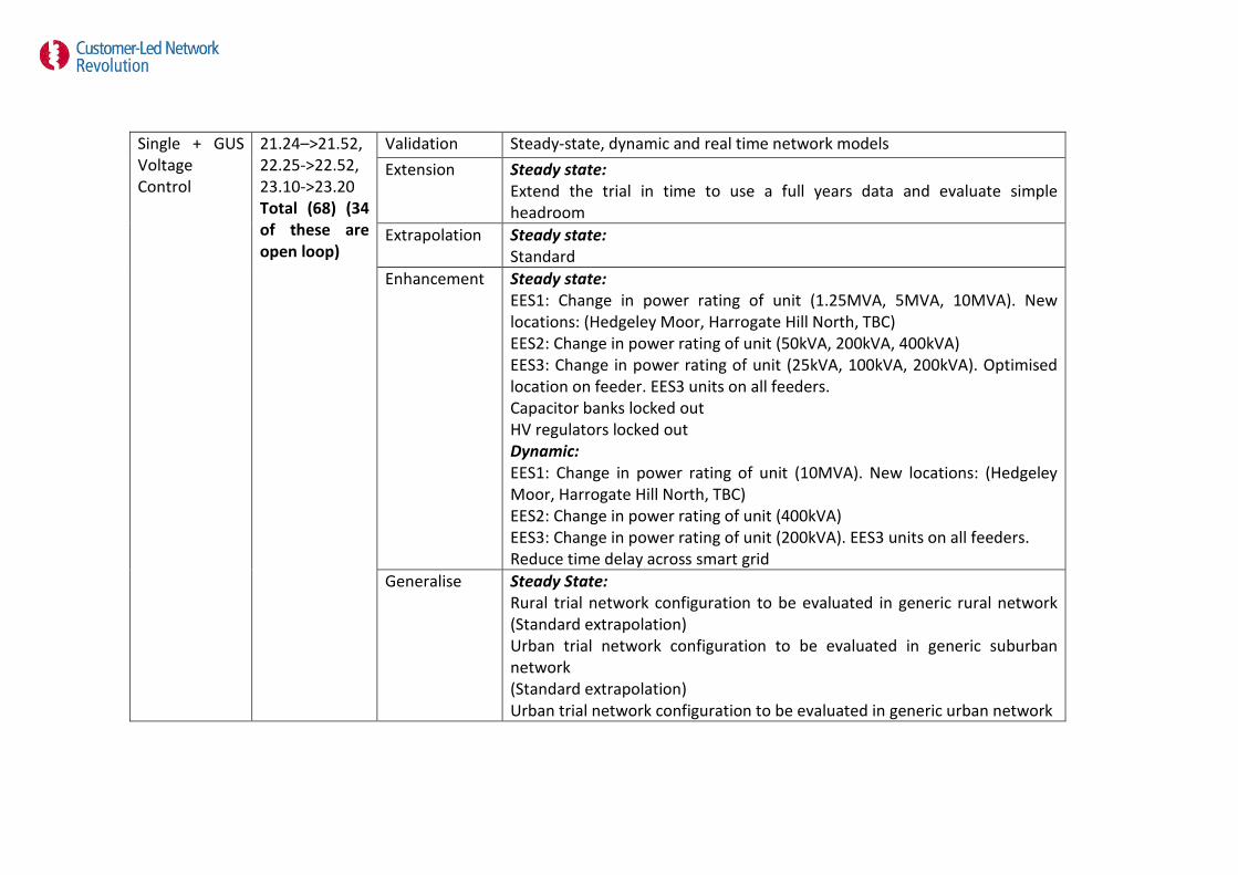
Single + GUS Voltage Control
21.24–>21.52, 22.25->22.52, 23.10->23.20 Total (68) (34 of these are open loop)
Validation Steady-state, dynamic and real time network models Extension Steady state:
Extend the trial in time to use a full years data and evaluate simple headroom
Extrapolation Steady state: Standard
Enhancement Steady state: EES1: Change in power rating of unit (1.25MVA, 5MVA, 10MVA). New locations: (Hedgeley Moor, Harrogate Hill North, TBC) EES2: Change in power rating of unit (50kVA, 200kVA, 400kVA) EES3: Change in power rating of unit (25kVA, 100kVA, 200kVA). Optimised location on feeder. EES3 units on all feeders. Capacitor banks locked out HV regulators locked out Dynamic: EES1: Change in power rating of unit (10MVA). New locations: (Hedgeley Moor, Harrogate Hill North, TBC) EES2: Change in power rating of unit (400kVA) EES3: Change in power rating of unit (200kVA). EES3 units on all feeders. Reduce time delay across smart grid
Generalise Steady State: Rural trial network configuration to be evaluated in generic rural network (Standard extrapolation) Urban trial network configuration to be evaluated in generic suburban network (Standard extrapolation) Urban trial network configuration to be evaluated in generic urban network

(Standard extrapolation) Urban trial network configuration to be evaluated in generic urban meshed network (Standard extrapolation)
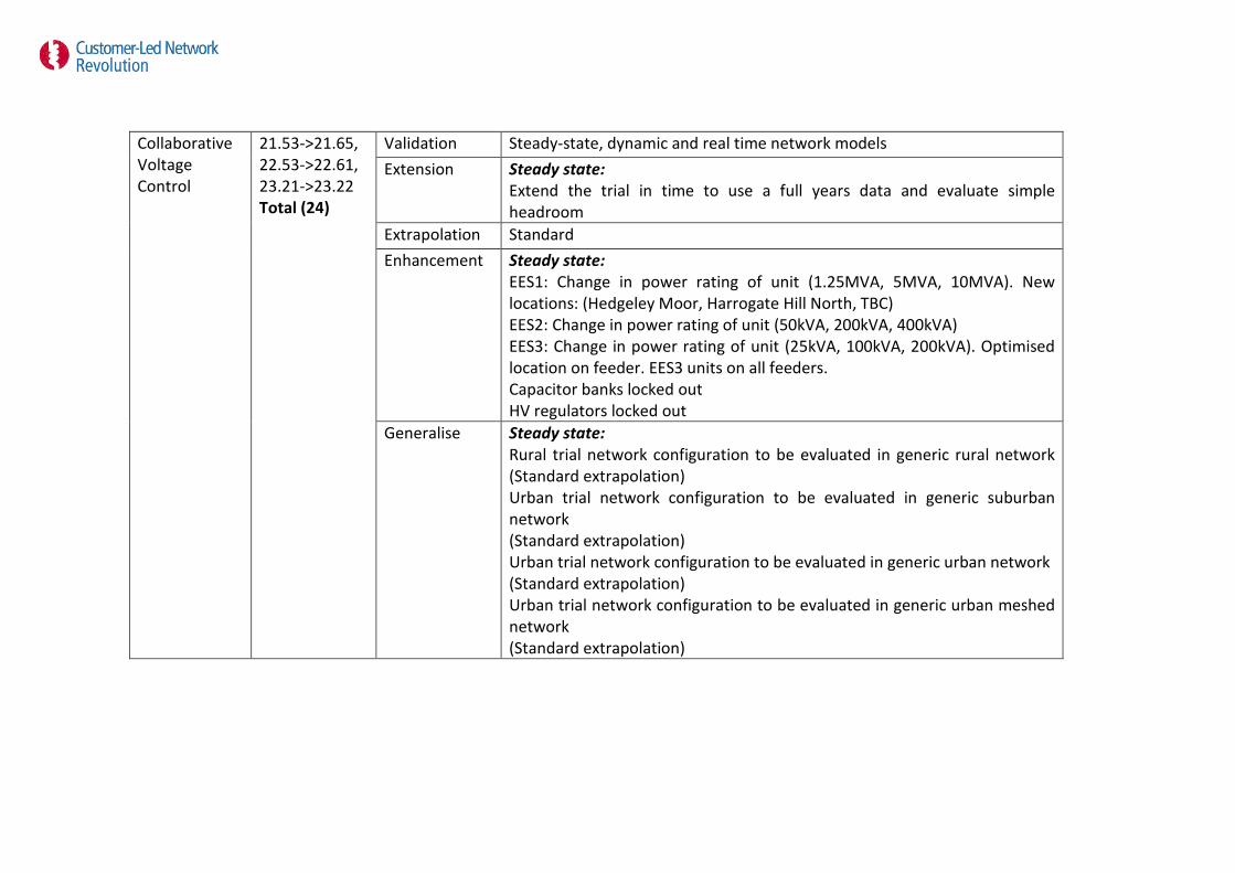
Collaborative Voltage Control
21.53->21.65, 22.53->22.61, 23.21->23.22 Total (24)
Validation Steady-state, dynamic and real time network models Extension Steady state:
Extend the trial in time to use a full years data and evaluate simple headroom
Extrapolation Standard Enhancement Steady state:
EES1: Change in power rating of unit (1.25MVA, 5MVA, 10MVA). New locations: (Hedgeley Moor, Harrogate Hill North, TBC) EES2: Change in power rating of unit (50kVA, 200kVA, 400kVA) EES3: Change in power rating of unit (25kVA, 100kVA, 200kVA). Optimised location on feeder. EES3 units on all feeders. Capacitor banks locked out HV regulators locked out
Generalise Steady state: Rural trial network configuration to be evaluated in generic rural network (Standard extrapolation) Urban trial network configuration to be evaluated in generic suburban network (Standard extrapolation) Urban trial network configuration to be evaluated in generic urban network (Standard extrapolation) Urban trial network configuration to be evaluated in generic urban meshed network (Standard extrapolation)
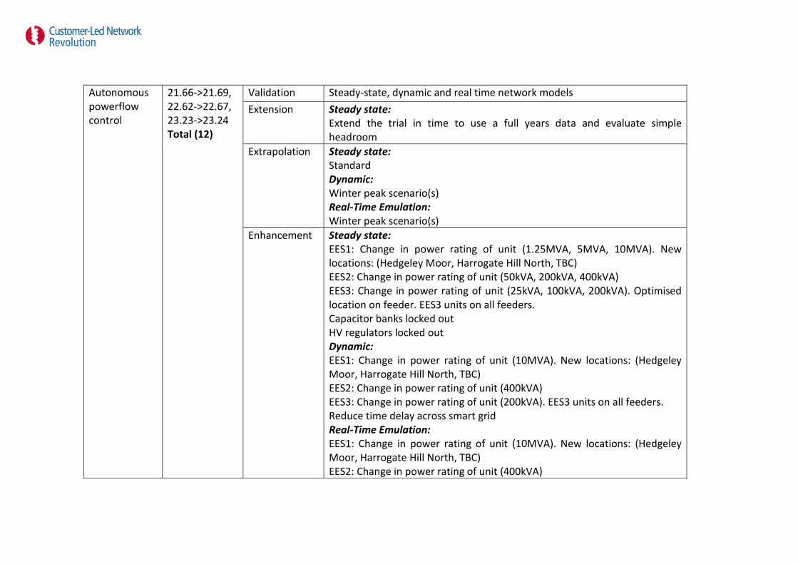
Autonomous powerflow control
21.66->21.69, 22.62->22.67, 23.23->23.24 Total (12)
Validation Steady-state, dynamic and real time network models Extension Steady state:
Extend the trial in time to use a full years data and evaluate simple headroom
Extrapolation Steady state: Standard Dynamic: Winter peak scenario(s) Real-Time Emulation: Winter peak scenario(s)
Enhancement Steady state: EES1: Change in power rating of unit (1.25MVA, 5MVA, 10MVA). New locations: (Hedgeley Moor, Harrogate Hill North, TBC) EES2: Change in power rating of unit (50kVA, 200kVA, 400kVA) EES3: Change in power rating of unit (25kVA, 100kVA, 200kVA). Optimised location on feeder. EES3 units on all feeders. Capacitor banks locked out HV regulators locked out Dynamic: EES1: Change in power rating of unit (10MVA). New locations: (Hedgeley Moor, Harrogate Hill North, TBC) EES2: Change in power rating of unit (400kVA) EES3: Change in power rating of unit (200kVA). EES3 units on all feeders. Reduce time delay across smart grid Real-Time Emulation: EES1: Change in power rating of unit (10MVA). New locations: (Hedgeley Moor, Harrogate Hill North, TBC) EES2: Change in power rating of unit (400kVA)

EES3: Change in power rating of unit (200kVA). EES3 units on all feeders. Reduce time delay across smart grid
Generalise Steady state: Rural trial network configuration to be evaluated in generic rural network (Standard extrapolation) Urban trial network configuration to be evaluated in generic suburban network (Standard extrapolation) Urban trial network configuration to be evaluated in generic urban network (Standard extrapolation) Urban trial network configuration to be evaluated in generic urban meshed network (Standard extrapolation)
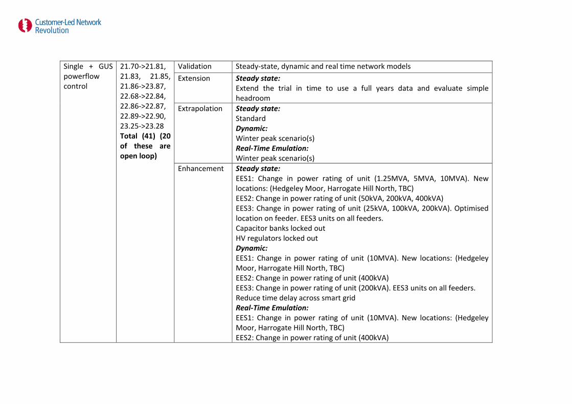
Single + GUS powerflow control
21.70->21.81, 21.83, 21.85, 21.86->23.87, 22.68->22.84, 22.86->22.87, 22.89->22.90, 23.25->23.28 Total (41) (20 of these are open loop)
Validation Steady-state, dynamic and real time network models Extension Steady state:
Extend the trial in time to use a full years data and evaluate simple headroom
Extrapolation Steady state: Standard Dynamic: Winter peak scenario(s) Real-Time Emulation: Winter peak scenario(s)
Enhancement Steady state: EES1: Change in power rating of unit (1.25MVA, 5MVA, 10MVA). New locations: (Hedgeley Moor, Harrogate Hill North, TBC) EES2: Change in power rating of unit (50kVA, 200kVA, 400kVA) EES3: Change in power rating of unit (25kVA, 100kVA, 200kVA). Optimised location on feeder. EES3 units on all feeders. Capacitor banks locked out HV regulators locked out Dynamic: EES1: Change in power rating of unit (10MVA). New locations: (Hedgeley Moor, Harrogate Hill North, TBC) EES2: Change in power rating of unit (400kVA) EES3: Change in power rating of unit (200kVA). EES3 units on all feeders. Reduce time delay across smart grid Real-Time Emulation: EES1: Change in power rating of unit (10MVA). New locations: (Hedgeley Moor, Harrogate Hill North, TBC) EES2: Change in power rating of unit (400kVA)
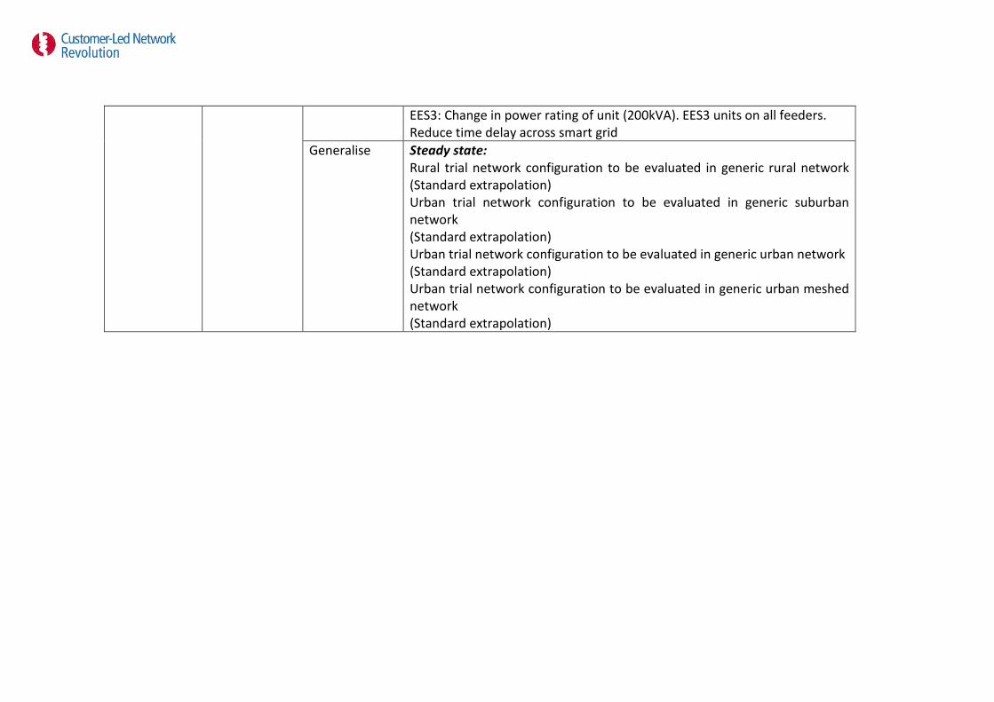
EES3: Change in power rating of unit (200kVA). EES3 units on all feeders. Reduce time delay across smart grid
Generalise Steady state: Rural trial network configuration to be evaluated in generic rural network (Standard extrapolation) Urban trial network configuration to be evaluated in generic suburban network (Standard extrapolation) Urban trial network configuration to be evaluated in generic urban network (Standard extrapolation) Urban trial network configuration to be evaluated in generic urban meshed network (Standard extrapolation)
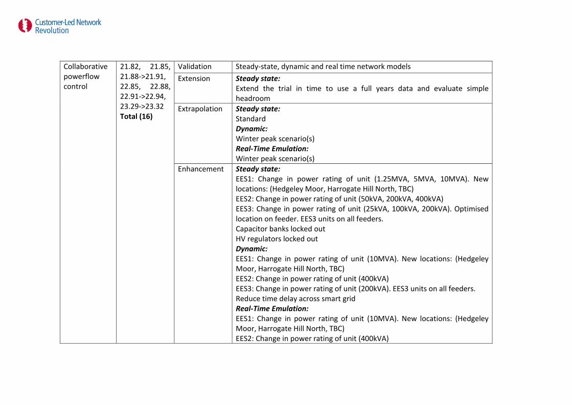
Collaborative powerflow control
21.82, 21.85, 21.88->21.91, 22.85, 22.88, 22.91->22.94, 23.29->23.32 Total (16)
Validation Steady-state, dynamic and real time network models Extension Steady state:
Extend the trial in time to use a full years data and evaluate simple headroom
Extrapolation Steady state: Standard Dynamic: Winter peak scenario(s) Real-Time Emulation: Winter peak scenario(s)
Enhancement Steady state: EES1: Change in power rating of unit (1.25MVA, 5MVA, 10MVA). New locations: (Hedgeley Moor, Harrogate Hill North, TBC) EES2: Change in power rating of unit (50kVA, 200kVA, 400kVA) EES3: Change in power rating of unit (25kVA, 100kVA, 200kVA). Optimised location on feeder. EES3 units on all feeders. Capacitor banks locked out HV regulators locked out Dynamic: EES1: Change in power rating of unit (10MVA). New locations: (Hedgeley Moor, Harrogate Hill North, TBC) EES2: Change in power rating of unit (400kVA) EES3: Change in power rating of unit (200kVA). EES3 units on all feeders. Reduce time delay across smart grid Real-Time Emulation: EES1: Change in power rating of unit (10MVA). New locations: (Hedgeley Moor, Harrogate Hill North, TBC) EES2: Change in power rating of unit (400kVA)

EES3: Change in power rating of unit (200kVA). EES3 units on all feeders. Reduce time delay across smart grid
Generalise Steady state: Rural trial network configuration to be evaluated in generic rural network (Standard extrapolation) Urban trial network configuration to be evaluated in generic suburban network (Standard extrapolation) Urban trial network configuration to be evaluated in generic urban network (Standard extrapolation) Urban trial network configuration to be evaluated in generic urban meshed network (Standard extrapolation)

Full system 21.92->21.97, 22.95->22.99, 23.33 Total (12)
Validation Steady-state, dynamic and real time network models Extension Steady state:
Extend the trial in time to use a full years data and evaluate simple headroom
Extrapolation Steady state: Standard Dynamic: Winter peak scenario(s) Real-Time Emulation: Winter peak scenario(s)
Enhancement Steady state: EES1: Change in power rating of unit (1.25MVA, 5MVA, 10MVA). New locations: (Hedgeley Moor, Harrogate Hill North, TBC) EES2: Change in power rating of unit (50kVA, 200kVA, 400kVA) EES3: Change in power rating of unit (25kVA, 100kVA, 200kVA). Optimised location on feeder. EES3 units on all feeders. Capacitor banks locked out HV regulators locked out Dynamic: EES1: Change in power rating of unit (10MVA). New locations: (Hedgeley Moor, Harrogate Hill North, TBC) EES2: Change in power rating of unit (400kVA) EES3: Change in power rating of unit (200kVA). EES3 units on all feeders. Reduce time delay across smart grid Real-Time Emulation: EES1: Change in power rating of unit (10MVA). New locations: (Hedgeley Moor, Harrogate Hill North, TBC) EES2: Change in power rating of unit (400kVA)

EES3: Change in power rating of unit (200kVA). EES3 units on all feeders. Reduce time delay across smart grid
Generalise Steady state: Rural trial network configuration to be evaluated in generic rural network (Standard extrapolation) Urban trial network configuration to be evaluated in generic suburban network (Standard extrapolation) Urban trial network configuration to be evaluated in generic urban network (Standard extrapolation) Urban trial network configuration to be evaluated in generic urban meshed network (Standard extrapolation)

References
[1] Northern PowerGrid, EA Technology, Durham University, and British Gas, "Optional
Appendix 4 - Methodology," OFGEM 2010. Available from:
https://clnr.sharepoint.com/CLNR%20Project%20BID/Methodology.pdf.
[2] P. Lyons, "Overview of Network Flexibility Trial Design for CLNR," CLNR, 2012.
Available from: https://clnr.sharepoint.com/DEI/DEI Document Library/DEI-CLNR-
FTA001-OverviewofNetworkFlexibilityTrialDesignforCLNR.docx, Date Accessed: 21st
August 2012.
[3] P. Wang, J. Yi, P. F. Lyons, D. Liang, P. C. Taylor, D. Miller, and J. Baker, "Customer
Led Network Revolution - Integrating renewable energy into LV networks using
energy storage," in CIRED Workshop 2012 - Integration of Renewables into the
Distribution Grid, Lisbon, Portugal, 2012.
[4] J. Yi, P. Wang, P. J. Davison, P. F. Lyons, D. Liang, P. C. Taylor, and D. Miller, "Demand
Side Response for Distribution Network Voltage Control assisted with Energy
Storage," IEEE Transactions on Smart Grids, Abstract submitted accepted, invited to
submit full paper expected 2013.
[5] J. Yi, P. Wang, P. J. Davison, P. F. Lyons, D. Liang, P. C. Taylor, D. Miller, and D.
Roberts, "Distribution Network Voltage Control Using Energy Storage and Demand
Side Response," in IEEE PES Innovative Smart Grid Technologies (ISGT) Europe
Conference, Berlin, Germany, 2012.
[6] P. Wang, J. Yi, P. J. Davison, P. F. Lyons, D. Liang, P. C. Taylor, and D. Miller,
"Integrating Electrical Energy Storage into Coordinated Voltage Control Schemes for
Distribution Networks," IEEE Transactions on Smart Grids, Abstract submitted to be
final submission to be confirmed expected 2013.
[7] S. R. Blake, J. Yi, P. C. Taylor, and D. Miller, "Use of Battery Storage to Increase
Network Reliability under Faulted Conditions," in CIGRÉ Regional South-East
European Conference, (RSEEC 2012), Hotel Hilton, Sibiu, Romania abstract accepted,
invited to submit full paper.
[8] DECC/OFGEM. "Smart Grid Forum," 2012 [cited 3rd August, 2012]; Available
from: http://www.ofgem.gov.uk/Networks/SGF/Pages/SGF.aspx.
[9] "The Electricity Safety, Quality and Continuity Regulations," UK, 2002.

[10] P. Lyons, "Experimental Investigation and Evaluation of Future Active Distribution
Networks," in School of Engineering and Computing Sciences. vol. PhD, Durham,
Durham University, 2010.
[11] J. Zhang, H. Cheng, and C. Wang, "Technical and economic impacts of active
management on distribution network," International Journal of Electrical Power
& Energy Systems, vol. 31, pp. 130-138, 2009/3//. Available
from: http://www.sciencedirect.com/science/article/pii/S0142061508001026.
[12] EA Technology Limited, "Assessing the Impact of Low Carbon Technologies on Great
Britain’s Power Distribution Networks," Smart Grids Forum - WS3, 31st July 2012.
Available
from: http://www.ofgem.gov.uk/Networks/SGF/Publications/Documents1/WS3%20
Ph2%20Report%20Issue%203-1%20-%2031-Jul-12.pdf.
[13] P. Trichakis, P. C. Taylor, G. Coates, and L. M. Cipcigan, "Distributed control approach
for small-scale energy zones," Proceedings of the I MECH E Part A Journal of Power
and Energy, vol. 222, p. 137, 2008. Available
from: http://www.ingentaconnect.com/content/pep/jpe/2008/00000222/00000002
/art00001.

For enquires about the project Contact [email protected]
www.networkrevolution.co.uk
Copyright Northern Powergrid (Northeast) Limited, Northern Powergrid (Yorkshire) Plc, British Gas Trading Limited and the University of Durham 2014