Embed Size (px)
DESCRIPTION
out
Citation preview

7/17/2019 Out
http://slidepdf.com/reader/full/out563db8eb550346aa9a9832bf 1/24
i
UNIVERSITY OF OKLAHOMA
GRADUATE COLLEGE
SURFACE CHARACTERIZATION AND TRIBOLOGY IN FLAT LAPPING OF
METALS
A DISSERTATION
SUBMITTED TO THE GRADUATE FACULTY
in partial fulfillment of the requirements for the
Degree of
DOCTOR OF PHILOSOPHY
By
CASMIR I. AGBARAJI
Norman, Oklahoma2008

7/17/2019 Out
http://slidepdf.com/reader/full/out563db8eb550346aa9a9832bf 2/24
3331070
3331070
2008

7/17/2019 Out
http://slidepdf.com/reader/full/out563db8eb550346aa9a9832bf 3/24
ii
SURFACE CHARACTERIZATION AND TRIBOLOGY IN FLAT LAPPING OF
METALS
A DISSERTATION APPROVED FOR THE
SCHOOL OF INDUSTRIAL ENGINEERING
BY
Dr. Shivakumar Raman, Chair
Dr. Theodore B. Trafalis
Dr. Floyd H. Grant
Dr. Chandra S. Rai
Dr. Thomas L. Landers

7/17/2019 Out
http://slidepdf.com/reader/full/out563db8eb550346aa9a9832bf 4/24
iii
© Copyright by CASMIR I. AGBARAJI 2008All Rights Reserved.

7/17/2019 Out
http://slidepdf.com/reader/full/out563db8eb550346aa9a9832bf 5/24
iv
ACKNOWLEDGMENTS
First and foremost, my thanks go to the chairman of my committee, Dr.
Shivakumar Raman, who helped me achieve my childhood dream. Also, I would like toacknowledge the invaluable contribution of other members of my committee: Dr.
Theodore B. Trafalis, Dr. Floyd H. Grant, Dr. Chandra S. Rai, and Dr. Thomas L.
Landers. I am greatly indebted to Brent Dustman of EATON Corporation, for giving me
a plant tour of EATON Lapping Department in Shawnee, Oklahoma, which broadened
my scope of knowledge in lapping operation. I am grateful to Gerard Pardeilhan of the
Precision Optics Equipment, Strasbaugh, for his help and time when I struggled with the
lapping machine.
My special thanks are extended to Dr. P. Larson of the Samuel Roberts Noble
Electron Microscopy Laboratory, University of Oklahoma, for his help in the scanning of
my samples with a scanning electron microscope. I would like to express my sincere
gratitude to Dr. M.C. Altan of the School of Aerospace and Mechanical Engineering,
University of Oklahoma, for allowing me use of his viscometer. I am very thankful to the
School of Industrial Engineering, University of Oklahoma, for awarding me a scholar
fellowship, which supported me through this long journey. Also, my special thanks go to
the Department of Industrial Engineering staff, Amy Piper, Cheryl Carney, and Jean
Shingledecker for their assistance in my work.
I would like to express my appreciation to other students in the School of
Industrial Engineering, and all my friends at the University of Oklahoma, who
contributed in one way or the other to make my stay in Norman very memorable. In
addition, I would like to thank my nephew, Chuka, and my nieces, Ije and Chioma for
their invaluable support. Finally, I must acknowledge the moral support and love from
my parents, my elder brother, Vincent Agbaraji, M.D., my younger brother, Canice, my
sister, Olivia and her husband, Linus. It was a rough road, but you supported me along
the way. Thank you.

7/17/2019 Out
http://slidepdf.com/reader/full/out563db8eb550346aa9a9832bf 6/24
v
TABLE OF CONTENTS
Page
LIST OF TABLES ......................................................................................... viii
LIST OF FIGURES .......................................................................................... ix
ABSTRACT ..................................................................................................... xi
CHAPTER
1. INTRODUCTION ....................................................................................... 1
1.1 Types of Lapping .............................................................................. 11.2 Functions of Lapping ......................................................................... 2
1.3 Applications of Lapping .................................................................... 31.4 Problem Definition ............................................................................. 3
1.5 Research Objective and Methodology ................................................ 4
2. PRINCIPLES OF TRIBOLOGY .................................................................. 62.1 Friction ............................................................................................. 7
2.1.1 Mechanism of Friction ........................................................ 72.1.2 Laws of Friction .................................................................. 9
2.1.3 Types of Friction ............................................................... 122.1.4 Detrimental Effects of Friction .......................................... 15
2.1.5 Beneficial Effects of Friction ............................................ 162.1.6 Reduction of Friction ........................................................ 17
2.1.7 Friction in Lapping ............................................................ 172.2 Surface Texture ............................................................................... 19
2.2.1 Surface Finish and Surface Integrity ................................. 212.3 Wear ............................................................................................... 22
2.3.1 Types of Wear ................................................................... 232.3.2 Abrasive Wear (Two-body and Three-body Wear) ............ 23
2.3.3 Adhesive Wear ................................................................. 272.3.4 Attrition Wear ................................................................... 28
2.3.5 Chemical Wear (Corrosive or Oxidation Wear) ................. 292.3.6 Erosion Wear .................................................................... 29
2.3.7 Fatigue (Impact Wear) ...................................................... 292.3.8 Fretting Wear .................................................................... 29
2.4 Lubrication ...................................................................................... 302.4.1 Types of Lubrication ......................................................... 30
2.4.2 Boundary Lubrication ....................................................... 302.4.3 Fluid-film Lubrication ....................................................... 30
2.4.4 Solid Lubrication .............................................................. 32

7/17/2019 Out
http://slidepdf.com/reader/full/out563db8eb550346aa9a9832bf 7/24
vi
3. LITERATURE REVIEW .......................................................................... 333.1 Abrasive Machining Techniques ..................................................... 34
3.1.1 Buffing ............................................................................. 343.1.2 Grinding ........................................................................... 35
3.1.3 Honing .............................................................................. 35
3.1.4 Polishing ........................................................................... 353.1.5 Ultrasonic Machining and Rotary Ultrasonic Machining .... 363.1.6 Wire Brushing .................................................................. 36
3.2 Abrasives ........................................................................................ 373.2.1 Properties of Good Abrasives ............................................. 37
3.2.2 Types of Abrasives ............................................................ 393.3 Hardness Tests ................................................................................ 43
3.4 Lapping of Ceramics ....................................................................... 463.5 Lapping of Glass ............................................................................. 50
3.6 Lapping of Metals ........................................................................... 533.7 Frictional Force Models ................................................................... 63
4. METHODOLOGY .................................................................................... 70
4.1 Equipment ....................................................................................... 704.1.1 Maintaining Wheel Flatness .............................................. 71
4.1.2 Lapping Machine Materials ............................................... 724.1.3 Lapping Vehicle Fluids ..................................................... 72
4.2 Design of Experiment ...................................................................... 734.2.1 Independent Variables or Allowed-to-vary Factors ........... 73
4.2.2 Dependent Measures or Response Variables ...................... 744.2.3 Control Variables or Held-constant Factors ........................ 76
4.3 Sample Tolerance ............................................................................ 764.4 Precautions ...................................................................................... 78
4.5 Test Procedure ................................................................................ 794.5.1 Data Collection ................................................................. 82
4.5.2 Profilometry ...................................................................... 834.6 Observations ................................................................................... 87
4.7 Quality Control - Burn Test ............................................................. 88
5. MATERIALS CONSIDERATIONS .......................................................... 905.1 EDS Analysis .................................................................................. 90
6. IMAGE PROCESSING ............................................................................. 108
6.1 Geometric SEM Analysis ............................................................... 1086.2 Reconstruction of 3-D Images ....................................................... 118
6.3 MATLAB Image Processing ......................................................... 128
7. RESULTS and ANALYSIS ....................................................................... 1327.1 Analyses of Results ....................................................................... 132
7.1.1 Initial Lapping ................................................................ 1337.1.2 Final Lapping .................................................................. 138

7/17/2019 Out
http://slidepdf.com/reader/full/out563db8eb550346aa9a9832bf 8/24
vii
7.2 Statistical Analysis ......................................................................... 1427.3 Assumptions................................................................................... 163
7.4 Tribology of Lapping ..................................................................... 1637.4.1 Frictional Force as a function of Viscosity ....................... 164
7.4.2 Rolling Friction as a Function of Radius of Specimen ..... 168
7.4.3 Rolling Friction as a Function of Slip Velocity and RollingVelocity .......................................................................... 1697.4.4 Force Sensor Model ........................................................ 172
7.4.5 Temperature Model.......................................................... 1727.4.6 Motor Constant Model ..................................................... 173
7.4.7 Three-body Wear Model in Flat Lapping of Metals .......... 1827.5 Power Consumed in Lapping ......................................................... 183
7.6 Finite Element Analysis ................................................................. 1857.7 Redox Chemistry in Lapping .......................................................... 187
8. CONCLUSIONS and RECOMMENDATIONS ..................................... 198
8.1 Forces and Sliding Friction ............................................................. 1988.2 Three-body Friction Defects ........................................................... 199
8.3 Effects of Lapping Parameters ........................................................ 2008.4 Qualitative Observation of the Interface ......................................... 200
8.5 Substantiating Theories ................................................................. 2028.6 Contributions and Conclusions ....................................................... 203
8.7 Recommendations for Further Work............................................... 204
REFERENCES ............................................................................................. 205
APPENDICES .............................................................................................. 211
A: Definitions and Properties of Materials ..................................... 211
B: EDS and Anaglyph Stereopairs of Specimens before Lapping ... 235
C: Indentation Made on Samples before Lapping ........................... 249
D: MATLAB Code for Image Processing ........................................ 250
E: Average Roughness ...................................................................... 253
F: SAS Output ................................................................................... 262
G: Types of Velocity .......................................................................... 284
H: Connection of Amp Meter ........................................................... 285
I: Frictional Torque Data ................................................................. 286
J: FEA Results ................................................................................... 289

7/17/2019 Out
http://slidepdf.com/reader/full/out563db8eb550346aa9a9832bf 9/24
viii
LIST OF TABLES
Table Page
1. Comparison of Different Abrasive Machining Processes ............................. 372. Abrasive Grain Sizes ................................................................................... 383. Knoop Hardness Number and Mohs Hardness Number ............................... 45
4. Specifications of Equipment ....................................................................... 705. Experimental Layout ................................................................................... 74
6. Profilometer Parameters ............................................................................... 857. Advantages of EDS and WDS ..................................................................... 92
8. Composition of Aluminum 2024 before Lapping ........................................ 959. Composition of 304 Stainless Steel before Lapping ..................................... 95
10. Composition of 1018 Steel before Lapping ................................................. 9611. Area of 304 Stainless Lapped with SiC ..................................................... 129
12. Material Removal Rate of Al 2024 Using 23µm Abrasive ........................ 13413. Material Removal Rate of 304 Stainless Steel Using 23 µm Abrasive ....... 134
14. Material Removal Rate of 1018 Steel Using 23 µm Abrasive .................... 13515. Roughness Values of Al 2024 Using 23 µm Abrasive ............................... 136
16. Roughness Values of 304 Stainless Steel Using 23 µm Abrasive ............... 13717. Roughness Values of 1018 Steel Using 23 µm Abrasive ........................... 137
18. Material Removal Rate of Al 2024 Using 8 µm Abrasive .......................... 13819. Material Removal Rate of 304 Stainless Steel Using 8 µm Abrasive ......... 139
20. Material Removal Rate of 1018 Steel Using 8 µ m Abrasive ...................... 13921. Roughness Values of Al 2024 Using 8 µm Abrasive ................................. 141
22. Roughness Values of 304 Stainless Steel Using 8 µm Abrasive ................ 14123. Roughness Values of 1018 Steel Using 8 µm Abrasive ............................. 142
24. MRR ANOVA Summary Results .............................................................. 14325. Ra ANOVA Summary Results ....................... ............................ ......................... . 143
26. Viscosity of Abrasives as a Function of Time ........................................... 16727. Mean Frictional Force and Coefficient of Friction ..................................... 181
28. Redox Chemistry of White Al2O3 Abrasives and Metal Alloys. ... ..................... 189
29. Redox Chemistry of SiC Abrasives and Metal Alloys. ........ .......................... .... 195

7/17/2019 Out
http://slidepdf.com/reader/full/out563db8eb550346aa9a9832bf 10/24
ix
LIST OF FIGURES
Figure Page
1. Microscopic Mechanism of Friction .............................................................. 92. Apparent Area - Actual Area of Contact ..................................................... 113. Normal Force vs. Friction Force ................................................................. 13
4. Friction in Lapping ..................................................................................... 185. Diagram of a Surface Texture . .................................................................... 21
6. Modes of Abrasives Wear. ........................................................................... 257. Adhesion Force ............................................................................................ 28
8. Lapping Precedence .................................................................................... 369. Maintaining Flatness of Lapping Plate ........................................................ 71
10. Specimen .................................................................................................... 7711. Experimental Setup - Strasbaugh. ................................................................ 81
12. Fluke 45 Dual Display Multimeter.. ............................................................. 8213. Data Collection Scheme . ............................................................................. 83
14. Mitutoyo Surftest 211 Profilometer ............................................................ .8415. Scanning Electron Microscope - Carl Zeiss DSM 960 A .............................. 86
16. SEM Micrographs of Abrasives Grains ........................................................ 9117. Energy Dispersive Spectrometer (EDS) of Aluminum Oxide . ..................... 93
18. Energy Dispersive Spectrometer (EDS) of Garnet and Silicon Carbide ....... 9419. EDS of Aluminum 2024 after Lapping ........................................................ 98
20. EDS of 304 Stainless Steel after Lapping . ................................................. 10121. EDS of 1018 Steel after Lapping . .............................................................. 104
22. SEM Micrographs of Lapped Al 2024 ....................................................... 10823. SEM Micrographs of Lapped 304 Stainless Steel ...................................... 111
24. SEM Micrographs of Lapped 1018 Steel ................................................... 11425. SEM Micrographs of Al 2024 at 0
oand 6
oprior to Lapping ....................... 118
26. SEM Micrographs of 304 Stainless Steel at 0oand 6
oprior to Lapping ...... 119
27. SEM Micrographs of 1018 Steel at 0oand 6
oprior to Lapping .................... 119
28. SEM Micrographs of Al 2024 at 0oand 6
o- Lapped with Garnet .............. 120
29. SEM Micrographs of 304 Stainless Steel at 0oand 6
o - Lapped
with Garnet ............................................................................................... 12030. SEM Micrographs of 1018 Steel at 0
oand 6
o- Lapped with Garnet .......... 121
31. 3-D Images of Al 2024 before Lapping ..................................................... 12232. 3-D Images of 304 Stainless Steel before Lapping .................................... 123
33. 3-D Images of 1018 Steel before Lapping ................................................. 12434. 3-D Images of Al 2024 after Lapping ........................................................ 125
35. 3-D Images of 304 Stainless Steel after Lapping ....................................... 12636. 3-D Images of 1018 Steel after Lapping .................................................... 127
37. Graph from MATLAB Showing 304 Stainless Steel Lapped with SiC ....... 13038. Graph from MATLAB Showing Al 2024 Lapped with Al2O3 ................... 130
39. Graph from MATLAB Showing 1018 Steel Lapped with Garnet ............... 13140. MRR vs. Hardness of Abrasives in Gram per Minute ................................ 140

7/17/2019 Out
http://slidepdf.com/reader/full/out563db8eb550346aa9a9832bf 11/24
x
41. MRR vs. Hardness of Abrasives in inch per Minute .................................. 14042. Surface Roughness Profile vs. Hardness of Abrasives ............................... 142
43. Two-Way Interaction between Abrasives and Workpiece .......................... 14444. Anaglyph Stereopair and Line Profile of Lapped Al 2024 ......................... 145
45. Anaglyph Stereopair and Line Profile of 304 Lapped Stainless Steel ......... 151
46. Anaglyph Stereopair and Line Profile of Lapped 1018 Steel ..................... 15747. Viscosity of Abrasives vs. Time ................................................................ 16848. Lapping Forces ......................................................................................... 170
49. Frictional Force vs. Time for Lapped Al 2024 ............................................ 17650. Frictional Force vs. Time for Lapped 304 Stainless Steel .......................... 177
51. Frictional Force vs. Time for Lapped 1018 Steel ....................................... 17952. Coefficient of Friction of 1018 Steel Lapped with SiC vs. Time. ................ 181
53. Von Mises Stress Map of Al 2024 ............................................................. 18654. Von Mises Stress Map of 304 Stainless ..................................................... 186
55. Von Mises Stress Map of 1018 Steel ......................................................... 187

7/17/2019 Out
http://slidepdf.com/reader/full/out563db8eb550346aa9a9832bf 12/24
xi
ABSTRACT
Lapping is a loose abrasive process employed to remove very small quantities of
materials leading to a good surface finish. This research makes several investigations on
the lapping process, both qualitative and quantitative. Lapping has been in existence for
several decades and yet remains more of an art rather than a science. The principal
objective is to create a scientific basis to the study of lapping common metals with
common abrasives. The important goals are to study friction, material removal rate,
roughness, surface characterization, redox chemistry, burn, and microvoids during flat
lapping of aluminum 2024, 304 stainless steel, and 1018 steel. The effects of different
abrasives: garnet, silicon carbide, and white aluminum oxide were studied experimentally
while lapping aluminum 2024, 304 stainless steel, and 1018 steel.
In addition, the area of lapped parts, unfinished zones, and scratched zones were
determined using image analysis. Although the aim of lapping is to improve surface
finish, sometimes parts are rejected after lapping because of burn, friction, incomplete
lapping, scratches, microvoids, and wear. Scratches may be caused by excessive load,
low supply of abrasive slurry, or high friction and burn may be caused by excessive load.
Uneven distribution of load occurs when the lapping table is not flat, but rather concave
or convex in shape. The factors that cause burn, scratches, and incomplete lapping
should be minimized.
A new method is proposed for calculation of frictional force during lapping using
the current consumed in the process. The effects of different abrasives on material
removal rate and surface finish on three different types of work materials were evaluated
quantitatively. It was found that silicon carbide and white aluminum oxide abrasives

7/17/2019 Out
http://slidepdf.com/reader/full/out563db8eb550346aa9a9832bf 13/24
xii
removed more material per minute than garnet. Furthermore, from geometric and Energy
Dispersive Spectroscopy (EDS) analysis obtained using a Scanning Electron Microscope
(SEM), it was confirmed that some abrasives became embedded into the lapped metal
substrates. No burn was observed on the lapped samples. Scratches and unfinished
lapped parts were observed primarily in 304 stainless steel. There were little or no
scratches found on lapped Al 2024 and 1018 steel.
Based on the net cell reaction potentials using the Nernst equation, the possible
reactions during the lapping process are reactions between magnesium and its hydroxides
and white aluminum oxide abrasive. Also, SiO2 from SiC abrasives oxidized Al, Mn,
Mg, and Ti in Al 2024 as well as Mn in 304 stainless steel, and Al and Mn in 1018 steel.
Analysis of Variance (ANOVA) was performed using Statistical Analysis Software
(SASTM
9.1) in order to determine the effects of each variable. ANOVA results revealed
that the main effects of abrasive types, size of abrasives, and type of work material had
statistically significant influence on material removal rate and surface finish.

7/17/2019 Out
http://slidepdf.com/reader/full/out563db8eb550346aa9a9832bf 14/24
1
CHAPTER 1
INTRODUCTION
Lapping can be defined as a low-velocity and low-pressure finishing operation in
which small amounts of material are removed from the workpiece (usually flat,
cylindrical or curved surfaces) by means of loose abrasive grains (Lynah and Hoffman,
1989; Davis, 1994). This finishing operation method was first applied in ancient times
when grinding and polishing precious metals.
1.1 Types of Lapping
The lapping process can be classified as single-sided lapping or double-sided
lapping. If only one side of the work material is lapped against the lapping plate, the
process is regarded as a single-sided lapping operation. In contrast, if the workpiece is
positioned between two parallel lapping plates (lap), and the abrasive slurry is made to
complete the lapping operation on both sides of the work material simultaneously, then
this is called double-sided lapping. According to Subramanian (1994), some of the
advantages of double-sided lapping over single-sided lapping include: time savings,
higher quantities of production, reduction of internal stresses, lower heat generation, and
better efficiencies.

7/17/2019 Out
http://slidepdf.com/reader/full/out563db8eb550346aa9a9832bf 15/24
2
1.2 Functions of Lapping
Lynah and Hoffman (1989); Davis (1994) enumerated the features and functions
of lapping. Lapping is a low-velocity, low-pressure abrading technique, in which one or
more of the following objectives are accomplished:
Form accuracy (i.e., flatness in the case of flat objects and sphericity of round
objects);
Surface finishing (i.e., damaged and subsurface layers are removed during the
lapping process);
Correcting minor imperfections;
Making close fit or alignment between mating work surfaces;
Elongating wear life, reducing risk of seizure and noise, and maximizing the
percentage bearing area since hills and valleys on the surface of workpiece are
minimized;
Reducing the possibility of re-hardened and de-carburized areas on hardened or
heat treated components since less heat is generated in lapping than other
finishing operations;
Achieving extreme parallelism; and
Eliminating stresses in the workpiece.
Lapping does not require the use of chucks or other holding/clamping devices.
Therefore, form tolerance (circularity, cylindricity, flatness, straightness, and
sphericity), orientation tolerance (angularity, parallelism, and perpendicularity), and
size tolerance are improved.

7/17/2019 Out
http://slidepdf.com/reader/full/out563db8eb550346aa9a9832bf 16/24
3
1.3 Applications of Lapping
Lapping operations can be applied to materials that require high dimensional
accuracy and fine surface finishing, including: crankshafts, cutting tools and dies,
cylinders, gears, industrial ceramics (e.g., heat exchangers), magnetic memory disks,
optical component fabrication (i.e., glass and lenses), piston rings, precision components
(such as gage blocks and micrometers), and valves.
1.4 Problem Definition
Although the aim of lapping is to improve surface finish, sometimes parts are
rejected after lapping because of burn, friction, incomplete lapping, scratches,
microvoids, and wear. Scratches can be due to excessive load, low supply of abrasive
slurry or high friction. Incomplete lapping can be caused when there is an uneven
distribution of load. Uneven distribution of load occurs when the lapping table is not flat,
but rather either concave or convex in shape. Therefore, the factors that cause burn,
scratches, and incomplete lapping should be minimized.
In a competitive market, there is a need to produce metal components with good
surface finish, integrity, and dimensional accuracy. During a lapping operation, friction,
roughness, and wear affect dimensional accuracy, life span of parts, and material removal
rate. In other words, friction force and wear of the work material increase during the
course of a lapping operation. Friction is produced between the lapping plate and
workpiece by an application of lapping pressure. During the course of lapping operation,
the actual area of contact increases because of an improvement in surface finish. As a
result of an increase in the actual area of contact, friction increases, thereby leading to an

7/17/2019 Out
http://slidepdf.com/reader/full/out563db8eb550346aa9a9832bf 17/24
4
increase in power consumption. Also, an increase in friction increases the wear rate of
two or more surfaces in contact. Although the effect of friction in lapping is observed at
the microscopic level, this can lead to failure of the lapped surfaces over a period of time.
Furthermore, toxic chemicals may also result during the course of lapping.
1.5 Research Objective and Methodology
This research makes several investigations on the lapping process, both
qualitative and quantitative. The principal objective is to create a scientific basis for the
study of lapping common metals with common abrasives. Lapping has been in existence
for several decades and yet remains more of an art rather than a science. The important
goals are to study friction, material removal rate, roughness, surface characterization,
redox chemistry, burn, and microvoids during flat lapping of aluminum 2024, 304
stainless steel, and 1018 steel. In addition, the area of lapped parts, unfinished zones,
and scratched zones must determined. This research proposes two methods (motor
constant model and temperature model) for determining frictional force during lapping.
In addition, the effects of different abrasives on material removal rate and surface finish
on three different types of work materials were evaluated.
The most efficient abrasive for achieving a high material removal rate (MRR) or
lapping rate while machining a good surface finish was determined. An optimum lapping
pressure that gives a high MRR without causing breakage of the work material or
affecting the dimensional accuracy was established. Also, a suitable lapping speed and
lapping time was determined. Furthermore, wear tracks left on the workpiece as result of
abrasive grains in the lapping process were investigated. In order to avoid producing
7/17/2019 Out
http://slidepdf.com/reader/full/out563db8eb550346aa9a9832bf 18/24
5
toxic chemicals, redox chemistry was investigated before any lapping operation.
Fundamentally, benefits and effects of the lapping process are studied, shedding light on
the scientific basis that transforms lapping from art to engineering.
In order to determine the effects of each variable, an Analysis of Variance
(ANOVA) was performed using Statistical Analysis Software (SASTM
9.1). Based on the
results obtained from ANOVA, the main effects of abrasive types, size of abrasives, and
type of work material had statistically significant influence on material rate and surface
finish. Also, Finite Element Analysis (FEA) was performed in order to determine the
distribution of the displacement, strain, and stress when a normal load of 24.9 N (5.6 lbf)
was applied on the sample.
Chapter 2 discusses the principle of tribology. The literature review is presented
in Chapter 3 and Chapter 4 explains the methodology used in the research. In Chapter 5,
background information on the materials is provided. Image analysis of the materials
used is provided in Chapter 6. The results and analysis are discussed in Chapter 7.
Finally, contributions, conclusions, and recommendations are presented in Chapter 8.

7/17/2019 Out
http://slidepdf.com/reader/full/out563db8eb550346aa9a9832bf 19/24
6
CHAPTER 2
PRINCIPLES OF TRIBOLOGY
In this chapter, the concepts of tribology (friction, lubrication, and wear) are
explained. The mechanisms of friction, laws of friction, types of friction, and detrimental
and beneficial effects of friction are highlighted. Also, types of wear and lubrication are
discussed.
Tribology is the study of mechanisms of friction, lubrication, and wear of surfaces
that are in a relative motion. The term was originally derived from a Greek word: tribos,
meaning rubbing. The function of many mechanical systems depends on factors such as
friction, lubrication, and wear. It is necessary to take an adequate precaution in designing
of mechanical systems to avoid the inconvenience that emanate from friction and wear of
mechanical components.
According to Suh (1986), tribology deals with science and technology of
interfaces between two or more bodies that are in a relative motion. The nature and
impacts of the interactions that take place at the interface determines the extent of friction
and wear behavior of the materials. In a tribological process, the following interactions
are observed:
forces are generated and transmitted between the surfaces in contact;
energy is consumed;
physical and chemical properties of the materials are changed (i.e., density,
melting point, specific heat, thermal expansion, thermal conductivity, electrical
properties, optical properties, corrosion, and oxidation);
7/17/2019 Out
http://slidepdf.com/reader/full/out563db8eb550346aa9a9832bf 20/24
7
surface topography of the material is altered; and
loose abrasive wear particles are generated.
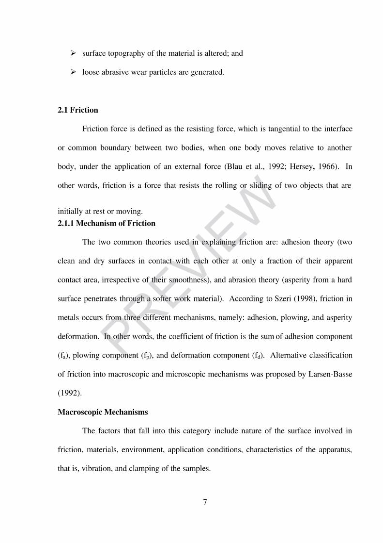
2.1 Friction
Friction force is defined as the resisting force, which is tangential to the interface
or common boundary between two bodies, when one body moves relative to another
body, under the application of an external force (Blau et al., 1992; Hersey, 1966). In
other words, friction is a force that resists the rolling or sliding of two objects that are
initially at rest or moving.
2.1.1 Mechanism of Friction
The two common theories used in explaining friction are: adhesion theory (two
clean and dry surfaces in contact with each other at only a fraction of their apparent
contact area, irrespective of their smoothness), and abrasion theory (asperity from a hard
surface penetrates through a softer work material). According to Szeri (1998), friction in
metals occurs from three different mechanisms, namely: adhesion, plowing, and asperity
deformation. In other words, the coefficient of friction is the sum of adhesion component
(f a), plowing component (f p), and deformation component (f d). Alternative classification
of friction into macroscopic and microscopic mechanisms was proposed by Larsen-Basse
(1992).
Macroscopic Mechanisms
The factors that fall into this category include nature of the surface involved in
friction, materials, environment, application conditions, characteristics of the apparatus,
that is, vibration, and clamping of the samples.

7/17/2019 Out
http://slidepdf.com/reader/full/out563db8eb550346aa9a9832bf 21/24
8
Microscopic mechanisms
The microscopic mechanisms that contribute to friction are: adhesion interactions,
plowing interactions, asperities deformations (mechanical interaction of surface
asperities), deformation, or fracture of surface layers such as oxides, and interference, and
local plastic deformation.
Adhesion Interactions
One cause of friction in metals is the force of attraction, (i.e., adhesion). This
adhesion occurs between the contact regions of the surfaces, and these appear irregular
in shape when viewed under a microscope. The irregularities appear as hills (peaks) and
valleys when a load is applied between two surfaces in contact. The peaks adhere, or
weld to each other, and/or interlock with the valleys in the opposing surfaces as depicted
in Figure 1. Therefore, friction force arises from shearing the adhesion and/or weld,
which are formed at the actual area of contact between the asperities.
Plowing (Ploughing) Interactions
The frictional force results from plowing of harder metals through the surface of softer
materials. Plowing can also be defined as displacing of materials from a groove to the
sides. In other words, formation of grooves (ridges) is due to the plastic deformation of a
softer material by a harder material when two surfaces which are in a relative motion.
Asperity Deformations
This usually involves mechanical interaction of surface asperities. Asperity
deformation is the factor that is responsible for static coefficient of friction (Suh, 1986).

7/17/2019 Out
http://slidepdf.com/reader/full/out563db8eb550346aa9a9832bf 22/24
9
Interference and Local Plastic Deformation
Interference and local plastic deformation are caused by third bodies. For
example, accumulated wear particles trapped between two or more moving surfaces leads
to friction.
Deformation or Fracture of Surface Layers
Deformation or fracture of surface layers such as oxides can cause friction.
Figure 1. Microscopic Mechanism of Friction (Larsen-Basse, 1992).
2.1.2 Laws of Friction
The pioneering work in tribology was done by Amontons’ (1699) and Coulomb
(1785). More (1972); Fuller (1984); Szeri (1998) cited Amontons’ and Coulomb’s laws
of friction, which have been stated as follows:
(1) Frictional force is directly proportional to the applied load (Amontons’ 1st law,
WearParticles
Adhesive Surface Plowed Groove
OxideParticle
(a) Adhesion (b) Plowing
(c) Deformation
of Oxides (d) Interference and LocalPlastic

7/17/2019 Out
http://slidepdf.com/reader/full/out563db8eb550346aa9a9832bf 23/24
10
1699).
(2) Frictional force is independent of apparent area of contact (Amontons’ 2nd
law,
1699).
(3) Kinetic friction is independent of sliding velocity (Coulomb’s law, 1785).
(4) Static friction is higher than kinetic friction.
(5) Friction depends on the nature of the sliding surface.
The first two laws of friction were deduced by da Vinci (1519), and discussed by
Amontons (1699), but Coulomb (1785) proved these laws experimentally. These laws
are generally applied to dry friction and are still applicable to many engineering
problems.
Moore (1972) stated that friction force is a function of sliding velocity, properties
of work material, contact area, and surface finish of the wokpiece. Coulomb’s law of
friction is described mathematically in Equation (1). The friction force and coefficient of
friction are independent of apparent area of contact since the actual area of contact is less
than the apparent area of contact as shown in Figure 2. Friction force is higher in smooth
surfaces because of larger area of contact.
7/17/2019 Out
http://slidepdf.com/reader/full/out563db8eb550346aa9a9832bf 24/24
11
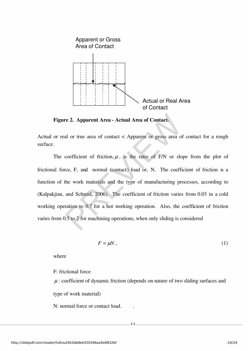
Figure 2. Apparent Area - Actual Area of Contact.
Actual or real or true area of contact < Apparent or gross area of contact for a rough
surface.
The coefficient of friction, µ , is the ratio of F/N or slope from the plot of
frictional force, F, and normal (contact) load or, N. The coefficient of friction is a
function of the work materials and the type of manufacturing processes, according to
(Kalpakjian, and Schmid, 2006). The coefficient of friction varies from 0.03 in a cold
working operation to 0.7 for a hot working operation. Also, the coefficient of friction
varies from 0.5 to 2 for machining operations, when only sliding is considered
N F µ = , (1)
where
F: frictional force
µ : coefficient of dynamic friction (depends on nature of two sliding surfaces and
type of work material)
N: normal force or contact load. .
Actual or Real Areaof Contact
Apparent or GrossArea of Contact