Embed Size (px)
Citation preview

OTC-28803-MS
Hebron Platform: Innovative Design and Efficient Execution
Widianto, ExxonMobil Development Company; Justin Chichester and Adel Younan, ExxonMobil ProductionCompany; Jameel Khalifa, ExxonMobil Development Company; Krishna Komperla, WorleyParsons; Knut Bidne,Kvaerner
Copyright 2018, Offshore Technology Conference
This paper was prepared for presentation at the Offshore Technology Conference held in Houston, Texas, USA, 30 April–3 May 2018.
This paper was selected for presentation by an OTC program committee following review of information contained in an abstract submitted by the author(s). Contents ofthe paper have not been reviewed by the Offshore Technology Conference and are subject to correction by the author(s). The material does not necessarily reflect anyposition of the Offshore Technology Conference, its officers, or members. Electronic reproduction, distribution, or storage of any part of this paper without the writtenconsent of the Offshore Technology Conference is prohibited. Permission to reproduce in print is restricted to an abstract of not more than 300 words; illustrations maynot be copied. The abstract must contain conspicuous acknowledgment of OTC copyright.
AbstractThe Hebron platform was successfully installed on the Grand Banks (Offshore Newfoundland and Labrador)in June 2017 with first oil produced in November 2017. It consists of a single shaft concrete Gravity BasedStructure (GBS) supporting an integrated drilling and production topsides. The design of the platform waschallenged by sub-arctic and extreme metocean conditions which required innovative design and layoutapproaches for many elements considered routine for typical platforms. This paper highlights the underlyinginnovative technologies, analytical and design methods as well as the capital-efficient execution strategiesemployed.
IntroductionThe Hebron Project is located in the Jeanne d'Arc Basin, ~350 kilometers offshore Newfoundland andLabrador (NL), approximately ~ 6 nm north of the Terra Nova Field and ~10 nm southeast of the Hiberniadevelopment. The Hebron Platform (Figure 1) is comprised of a concrete Gravity Based Structure (GBS)and topsides installed in 93 meters water depth. Produced crude oil is stored in the platform's storage cellsand pumped to shuttle tankers via an Offshore Loading System (OLS).
Concrete GBS's are proven concepts for arctic and sub-arctic regions in which robustness to ice loading(including iceberg impact) is a key design requirement. Considering their cost differential compared to otherconcepts, such as steel jackets and subsea solutions tied to floating production facilities, it is imperative tooptimize all aspects of design and execution. In this paper, key Hebron design challenges are presented,and innovative design solutions as well as capital efficient execution strategies are illustrated for both theconcrete GBS and steel topsides structure.
Additional information on Hebron Project are provided in Cornaglia (2018), Parker et al. (2018), Edwardset al. (2018), Haddock (2018), Perry et al. (2018), and Ryan et al. (2018).
2 OTC-28803-MS
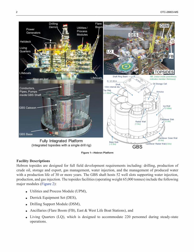
Figure 1—Hebron Platform
Facility DescriptionsHebron topsides are designed for full field development requirements including: drilling, production ofcrude oil, storage and export, gas management, water injection, and the management of produced waterwith a production life of 30 or more years. The GBS shaft hosts 52 well slots supporting water injection,production, and gas injection. The topsides facilities (operating weight 65,000 tonnes) include the followingmajor modules (Figure 2):
• Utilities and Process Module (UPM),
• Derrick Equipment Set (DES),
• Drilling Support Module (DSM),
• Ancillaries (Flare Boom (FB), East & West Life Boat Stations), and
• Living Quarters (LQ), which is designed to accommodate 220 personnel during steady-stateoperations.

OTC-28803-MS 3
Figure 2—Hebron Platform Construction Locations for Major Steel Modules and GBS
Figure 2 displays the construction locations for the GBS and all major modules.The total height of the platform with GBS is about ~235 meters, topsides length is ~183 meters and the
width is ~75 meters. The GBS concept includes a single shaft supporting the topsides and encompassesall wells in the initial development. It is designed to withstand sea ice, icebergs, meteorological andoceanographic conditions at the offshore Hebron site. The GBS is designed for an in-service life of 50 ormore years to support future developments.
The facility uses a single Offshore Loading System (OLS) which consists of a looped seafloor pipe andtwo separate subsea loading systems designed for an offloading rate of 6700 m3/h (~50,000 bbl/hr). The twobases, North and South, remove crude oil product from the offshore facility to an awaiting shuttle tanker. TheOLS includes two main offshore pipes with a 610 mm (24-inch) outer diameter, each running approximately2 km from subsea flanges at the base of the GBS to two separate Single Anchor Loading (SAL) bases.The two SAL bases are connected by a 610 mm (24-inch) outer diameter interconnecting offshore pipeapproximately 1.85 km long to form a looped piggable pipe. The pipe loop arrangement allows for piggingoperations to remediate the build-up of wax and to allow for flushing of the loading system. The loop canbe warmed prior to offloading by circulating warm oil. Flushing can be performed from the platform to theshuttle tanker, and vice versa for flushing of OLS hose system, if required. The launcher and receiver werealso designed to accommodate intelligent pigs for pipe inspection purposes.
Construction OverviewThe GBS was constructed from the base to the top at Bull Arm, approximately 150km Northwest of St.John's, NL, Canada. The lower portion of the GBS up to elevation ~27m was constructed in a dry-dockcreated by building a bund wall and dewatering the site behind it. Subsequently, the dock was flooded,bund wall removed, and GBS base (weighing approximately 180,000 tonnes) was towed approximately3km to a deep water site. The floating GBS was held in place with nine mooring lines while the remaining

4 OTC-28803-MS
construction was completed. All walls were constructed using the slipforming technique. More detailedinformation on the GBS construction and key quantities is presented in Widianto et al. (2016).
The topsides structure was fabricated in modules at various locations in NL and South Korea. Two ofthe topsides modules, UPM and DES, were fabricated in South Korea using "block/pancake" constructionmethods (i.e., the deck was fabricated, as much as practical, on a level-by-level basis and lifted overpre-installed columns and/or vertical bracing members), as shown in Figure 3. After the UPM and DESfabrication was completed, the modules were separately loaded-out to Heavy Transport Vessels to betransported to Bull Arm NL. All the other topsides modules were integrated to the main UPM module atthe finger pier in Bull Arm and the completed topsides structure was mated with the GBS while floating atthe deep water site. The mated platform was then towed offshore and installed at the final offshore location.
Figure 3—Hebron Topsides Block Division for Construction

OTC-28803-MS 5
Key ChallengesSome of the key design and execution challenges are discussed in this section.
Iceberg Impact LoadThe International Ice Patrol's website archive of icebergs drifting south of latitude 48° N dating back to1900's shows annual iceberg counts ranging from zero to more than 2,000. These icebergs drift into thearea where the Hebron platform is installed, and therefore it was essential to design the platform for icebergimpact.
Iceberg impact was considered at two return periods: 100-year and 10,000-year. The load generated at thefirst return period is an Extreme Level Ice Event (ELIE) while the second is considered an Abnormal-LevelIce Event (ALIE), a very rare event per ISO 19906. It should be noted that a 10,000-year event correspondsto an annual probability of exceedance of 10-4.
The development of iceberg impact loads for the Hebron GBS was based on state-of-the art probabilisticanalysis that satisfies ISO requirements. In addition, a range of expert opinions representing Type IIuncertainty was covered using a logic tree analysis. This uncertainty analysis ensures stability of the designrecipe as it protects it against future change of opinions.
The 10,000-year iceberg impact load on the caisson/ice wall (which is governed by the iceberg impact) is486 MN. More detailed information on the development of iceberg impact load for Hebron GBS is presentedin Widianto et al. (2013).
Single ShaftThe conceptual design of Hebron platform started with the topsides weight that was significantly less thanthe current operating weight of 65,000 tonnes. Therefore, a single shaft that offered benefits such as smallercaisson size (hence attracting less ice and wave loading), lighter GBS (attractive for floating stability), andless concrete volume was selected. Despite those benefits, the implementation of a single-shaft concept forHebron presented technical and execution challenges:
• The single concrete shaft results in fewer and more closely spaced topsides support points withhigher loads per support and a longer cantilevered topsides structure. This results in higher forceson topsides members and nodes which drives:
– Higher strength grout/concrete and denser reinforcement, which presented a significantconstructability challenge.
– Large topsides baseplates which presented a challenge to ensure that the grout would completelyfill the entire space underneath the baseplates.
– Larger member/node sizes and thicker plate thicknesses, beyond applicable limits of currentempirical existing code/standards formulas.
• The combination of a large diameter single-shaft, the relative shallow water depth over the caissonroof elevation, and large design wave height resulted in large wave slamming loads on the GBSshaft and on the underside of topsides, as discussed in the following section.
• All drilling, process, and piping interfaces with the oil storage cells and outside environment,needed to be located in a congested wet shaft (i.e., shaft filled with sea water) resulting inconstructability complexity.
A single shaft concept prevents the more traditional separation of utility and process components intoseparate GBS compartments. As such, close attention was paid to loss prevention challenges including thedesign of a submersible firewater pump arrangement within robust protective caissons, ventilation of theshaft to meet regulatory requirements, risk mitigation of potential dropped objects during drilling operations,and strategically placed blast and firewalls on the topsides.

6 OTC-28803-MS
Wave ImpactThe combination of GBS geometry, overall water depth, and metocean conditions resulted in large waveimpacts on the GBS shaft and underside of the topsides structure, and local upward accelerations on thetopsides structural steel and some equipment.
Figure 4 shows a schematic of the wave-structure interaction and snapshots from wave model tests. Thewave-structure interaction consists of the following (see the numbers shown in Figure 4 for illustration):
• Wave impact on the GBS shaft
1. The shallow water depth above the caisson causes a shoaling effect resulting in large waves thatbreak and accelerate the crest forward.
2. The accelerated crest causes a high wave impact load on GBS shaft. Wave model tests revealedthat these wave impact loads were higher than those based on current industry standard
• Wave run-up
3. The wave front runs up the shaft, impacting the underside of the topsides
• Rooster-tail: topsides
4. Due to the large shaft diameter, the wave front splits around both sides of the shaft and collidesat the back of the shaft (5), creating an upward jet (rooster-tail) that impacts the underside ofthe topsides
Figure 4—Hebron Platform Wave-Structure Interaction

OTC-28803-MS 7
More detailed information on wave model tests and the analysis approach to define the wave impactloads are presented in Oberlies et al. (2014).
The magnitude of the wave impact load is significant, up to about 2.2MPa pressure on the GBS shaft.This resulted in a design load of 108 MN within a 50m2 area placed everywhere along the circumferenceat the shaft just above the waterline.
In order to resist the impact load from the wave run-up and the "Rooster-tail", the underside of thetopsides’ cellar deck was shielded with wave slamming steel (Figure 5) consisting of 10-mm/12-mm thickplate stiffened by inverted T-stiffeners. This differentiates Hebron topsides from other topsides structures.Maintenance platform lugs were installed on the wave impact steel to facilitate periodic inspection.
Figure 5—Wave Slamming Steel Underside of the Cellar Deck
Crude ProcessingHebron's crude has a design API gravity of ~19° for its largest formation and required a combination ofunique topsides facility elements to economically produce. The facility includes provisions for gas injection,gas lift, and water injection for reservoir pressure maintenance and artificial lift. Processing of oil below22° API gravity traditionally requires large tanks or vessels with extended residence times to separate the

8 OTC-28803-MS
oil and water. ExxonMobil's onshore heavy oil facility in Chad utilizes ~20 acres of tankage and facilities toseparate and process the same nameplate capacity as Hebron (~150kbd) which is accomplished in ~4 acres.
Worldwide ConstructionAs described in the previous section, the construction of platform modules was performed in variouslocations worldwide. After being fabricated in South Korea and various steel fabrication yards in NL, alltopsides modules were transported to be integrated at the finger pier in Bull Arm NL. The upper right picturein Figure 1 shows the completed topsides (after integration of all modules).
Structurally, the topsides experienced multiple construction/transportation/temporary phases withvarious loading and support conditions different from those associated with the operation phase (Figure6). Since these temporary phases governed the design of many parts of the structure, various loads andsupport conditions during temporary phases were analyzed. "Locked-in" stresses were also accounted forin the design.
Figure 6—Structural Analysis Model and Various Support Conditions
Focus on large module dimensional control is critical for any integrated platform fabricated in multiplegeographic locations. In order to ensure that all modules fit together during fabrication and integrationwithout clashes, a comprehensive dimensional control survey program by an independent third party wascritical. While each fabricator was required to perform standard dimensional control, key integration andoperational dimensions were assessed by the same third party using state-of-the-art survey equipment,combined with detailed 3D modeling, and structural analysis (to estimate structural deformations during

OTC-28803-MS 9
various phases and adjust the survey results as necessary). This philosophy allowed Hebron to integrate allmodules at Bull Arm NL with no major clashes and ahead of schedule.
Effective management of interfaces among various Contractors (e.g., topsides and GBS Engineering,Procurement, Construction/Fabricators, Load-out, Load-in, Integration Contractor, Heavy Transport VesselsContractor, Marine Operations Contractor, etc.) was crucial in order to ensure smooth execution. In addition,effective weight control and weight management were one of the key enablers for successful integration.
Capital Efficient Design ConsiderationsCapital efficiency and project viability do not always emerge from a single decision, but from a series ofelegant solutions working together driving value into design. These solutions must work to overcome theproject's key challenges. This section presents several capital-efficient considerations implemented in thedesign of Hebron platform, which do not compromise the general code requirements. Optimization was ajoint effort among various parties to search for capital- efficient solutions.
Facility OptimizationThrough the use of Vessel Internal Electrostatic Coalescer (VIEC) in the main separator and the CompactElectrostatic Coalescer (CEC) in the second stage of separation, Hebron is able to reduce residence timesand process the full name plate capacity on an equivalent of 20% of onshore facilities spacing.
In addition to the above project enabling technologies, it is a combination of many technologicaladvancements working together that drives design efficiency while considering many of Hebron Platformunique considerations, specifically: an open platform architecture, strategic placement of fire and blast walls,cutting edge submersible and line shaft pumps, space and weight savings heat exchangers, and passiveexhaust coolers on the main power generation trains.
Open Platform Architecture and Strategic Placement of Blast and Fire Walls. Recognizing the platformis located in sub-arctic climate with less extreme temperatures than other true arctic environments, thetopsides was designed with open architecture and strategically placed blast walls that maximizes naturalventilation while providing fire and blast protection for key safety critical components. The blast walls wereplaced to segregate the LQ / utilities from the wellbay, wellbay from the processing section, processingsection from the east end lifeboats, and the DSM from the gas compression area.
Cutting Edge Submersible and Line Shaft Pumps. The Hebron platform single shaft configuration drivesall necessary firewater, seawater, and crude oil booster pumps to be placed in the same GBS shaft as thewellbay. As a result, a pump system that is mounted and retrievable from the topsides (without entering theGBS shaft for maintenance or operation) is required. This, coupled with the required air gap height of 30.4m between the topsides and the Mean Sea Level (MSL), drove the project to employ submersible seawaterpumps which are among the longest in industry (46.8 m) and the longest in industry line shaft crude boosterpumps (47.4 m) which lift crude from the GBS storage cells to topsides for offloading to shuttle tanker.The primary driver for the long length is the required air gap height between the topsides and sea levelto accommodate North Atlantic environmental conditions (e.g., large waves and icebergs with high sailheight). These pumps were specifically designed to work with the Hebron platform height and to minimizethe "on deck" footprint while still performing the intended functions.
Space and Weight Savings through Heat Exchanger Selection. All types of heat exchangers for allapplications were carefully selected to fully optimize the space, weight, and cost. As a result, the use ofmore conventional shell & tube exchangers was minimized in favor of more compact plate & frame andprinted circuit heat exchangers. In the gas compression trains, all gas cooling systems are printed circuit,allowing for a greatly reduced footprint and overall costs.
10 OTC-28803-MS
Passive Exhaust Coolers. During the first few years of operation, the Hebron platform produces morepower than is required to harvest energy through the waste heat recovery units. As a result, short term hotexhaust temperatures could limit access to the upper derrick which would infringe on important drillingequipment during prevailing wind conditions. The project identified and employed a passive exhaust plumecooling / dilution system which contains no moving parts and reduces the output exhaust temperature by upto 50%. This allows drilling to proceed unimpeded during unfavorable wind conditions without personnellimitations on the derrick during early field life. Additionally, the design geometry of the coolers allowedfor reduced wall thickness when compared to traditional exhaust stacks resulting in a lighter supportingstructure.
ConstructabilityThe design of GBS and topsides was done based on comprehensive constructability input fromConstruction/Fabrication Contractors throughout the design process starting from the conceptual phase.The constructability effort and feedback improved execution certainty and ultimately eliminated potentialschedule delays.
GBS. Constructability aspects were approached systematically beginning with the concrete mix designdevelopment program started prior to Front End Engineering Design (FEED), all continuing to the endof construction in the field. To accomplish this, a team of construction specialists was established at startof FEED. In order to improve constructability, numerous full-scale mock-ups were carried out during thedesign phase and are described in a later section of this paper.
Topsides. Realizing the critical path fabrication schedule, the South Korean fabricator identified keypersonnel who would be working on fabrication drawings, and these individuals were brought on board earlybefore the start of the detailed design phase. A procedure was established, which enabled the Fabricator'sengineers to review the topsides design drawings and make recommendations that were assessed andincorporated where possible into the EPC engineering design and drawings.
Some examples of notable Fabricator recommendations include:
• Preferred steel materials and sections. Using Fabricator "preferred" steel improved procurementand overall fabrication schedule.
• Efficient concentric nodes fabrication methods and procedures
• Weldability and welding clearances
• Fabrication dimensional tolerances
• Constructability input on wave slamming steel fabrication/welding
• Schedule-effective "block/pancake" construction methods. In addition to main deck levels whichare normally being constructed in block/pancake approaches, mezzanine decks were also fabricatedin parallel with the main decks and then placed on the corbels of the topsides columns. Sincemezzanine decks are not integrally built with topsides columns, in-situ welding and wait-timeswere eliminated, resulting in shorter overall fabrication time.
• Several highly involved topsides nodes and details were re-analyzed and detailed in a manner thatis easier and safer to build, due to the fact many of the large diameter nodes and wave slammingsteel created enclosed/ hazardous spaces while welding.
• Provisions to share cable tray space between the EPC and Fabricator in particular for fabricatordesigned cable runs
• Methods to handle 3D model exchange between the EPC designer and Fabricator
• Early methods to handle installation of key equipment

OTC-28803-MS 11
This early Fabricator input in the detailed design phase made it possible to fabricate the topsides primarysteel with minimal technical queries and redlining of drawings, which typically impacts the constructionschedule in many other projects. In essence, the Fabricator started shop drawing production based onContractors’ engineering drawings that had been fully endorsed by the Fabricator's Construction and Qualitydepartments. Ultimately the UPM module left the Fabrication yard with less than 0.5% nominal carryoverwork, far less than industry average during heated market conditions.
Topsides Concentric Nodes ConfigurationCompared to eccentric nodes commonly used in other topsides offshore structures, the concentric nodesconfiguration (with member work points having minimum possible eccentricities as shown in Figure 7)chosen for topsides nodes on the two main longitudinal frames resulted in more open space and optimizedthe total platform weight. However, this also presented some challenges on both design and fabrication.
Figure 7—Concentric Node Configuration
• Design Phase challenges:The geometry configuration of a complex concentric node shown in Figure 7 would not fully
align with the existing specified configuration of tubular joints in ISO codes (primary design codeof topsides) or API, such as T, K, Y, and X joints. Therefore, these complex nodes were designedin a two-step process that involved the initial design using code provisions, with appropriateinterpretations, and finalization of the design using FEA. For complex joints, compliance withstress limit criteria based on linear-elastic FEA would not produce the optimum design due tohot-spot (localized) stresses. Therefore, in order to produce weight-saving designs, a strain basedcriterion has been applied at the location of hot spot stress regions, using non-linear FEA (tocapture stress redistribution) with an appropriate material constitutive relationship that includesstrain hardening.
In addition, the design of joints had been performed for the actual combination of joint forcesat every node, for every load case, with no overdesign associated with using envelope maximumforces for the members, as normally done to save computational time and effort.
• Fabrication Phase challenges:

12 OTC-28803-MS
Fabrication of complex concentric nodes is challenging, especially during rolling and fitting-up curved stiffeners (phrased as ‘toe nail stiffeners) at the far side of the flange plates where thetubular members intersect the joints. Due to early Fabricator input implemented in design (such asmaximum plate thickness) and Fabricator experience and capability, rolled plated stiffeners up to90 mm thickness were successfully fabricated, fitted-in and welded in compliance to fabricationspecifications.
Topsides Design Consideration for Iceberg ImpactSurvey of icebergs indicated that a significant percentage of icebergs in the Grand Banks are "Dry-Dock"and "Pinnacle" icebergs, which tend to have high sail heights that could impact an overhanging deck of thetopsides structure. Unlike the concrete GBS, it is cost prohibitive to design the topsides structure for icebergimpact load. Design codes (CSA S471-06 and ISO 19906) require the use of an air gap (vertical distancebetween the underside of topsides structure and the sea level) to achieve 10-5 probability of iceberg impactingtopsides and permit iceberg management (utilizing supply vessels to tow icebergs away) in determinationof iceberg to topsides impact probability.
Since the air gap has complex impacts to drilling and production facility design as well as overall cost, itwas important to optimize the air gap distance. The probability of icebergs with high-sail height impactingan overhanging deck of topsides was computed using the Monte Carlo approach with over 1.5 millionsimulations. In order to meet the code requirement of 10-5 annual probability of impact, a 30.4m air gapwas selected and the LQ module was raised vertically an additional 10.8m. Iceberg Management with 80%effectiveness was also included, considering that Iceberg Management is a routine activity on Grand Banksfor protection of offshore facilities.
Non-Linear Finite Element Analysis (NLFEA)Internal forces used to design offshore concrete GBSs are typically calculated using linear-elastic finiteelement analysis. However, during analysis and design of Hebron platform, complex NLFEAs wereeffectively utilized for the analysis and design of the following:
• Ice walls subjected to 10,000-year return period iceberg impactNLFEA captured the redistribution in internal forces due the cracking of concrete under tension,
allowing the ice wall to carry more load as membrane compression rather than bending. This ismuch more efficient since concrete has a greater capacity to resist compression. Nonlinear behavioralso reduced the peak forces/moments due to redistribution. Compared to a linear elastic analyses,the use of NLFEA in ice walls design resulted in improved constructability and constructionsafety, considerable cost and schedule savings: ~3,500t less reinforcement; ~700t reduction in post-tensioning cables; and reduced risk of schedule delays. Detailed analysis and verification of theseNLFEA are presented in Widianto et al. (2013).
• GBS Shaft subjected to 100-year and 10,000-year return period wave impactThe use of NLFEA in the shaft reduced the peak tension in shaft walls due to overall bending
thereby reducing the reinforcement by 300t and, more importantly, reducing the number of layersof reinforcement from two layers to only one layer on each face of the shaft cross section, resultingin a more constructible shaft wall. The reduction of the amount of reinforcement in the criticalhigh density wave impact area was about 50% and crucial for a successful slipforming operationof the shaft.
Integrated Seismic Soil-Structure-Interaction (SSI)The implementation of an integrated seismic SSI proved to be efficient and effective in performing theseismic analysis and design of all components of the Hebron platform through consecutive project phasesand various contractor structural models.

OTC-28803-MS 13
The method consists of the following steps (Younan et al. (2015)):
1. Developing a benchmark SSI one-step model for GBS and topsides, which was maintained by an SSIexpert company
2. Providing impedance functions and seafloor motions to EPC contractors for use in structural models3. EPC contractors running structural models with provided impedances and seafloor motions4. Acceleration response spectra at a number of GBS and topsides locations, computed by contractor
models (in various parts of the world), must match those obtained by the benchmark SSI model.
This approach enabled different EPC contractors (GBS and topsides) to perform their own separate SSIanalysis using the same foundation properties developed by the geotechnical contractor, resulting in a moreefficient design process with different levels of detailing according to the component of interest.
Foundation OptimizationHebron GBS has a flat, circular base slab with 500 mm deep soil skirts. Several key considerations relatedto the foundation design optimization for the Hebron GBS are as follows (Tistel et al. (2015)):
• Elimination of scour protectionGBSs located on sand are in some cases subjected to scour, especially around corners and edges
of the structure where the seabed current is amplified. The circular shaped foundation for Hebronwas favorable when considering scour. Furthermore, a comprehensive scour risk evaluation wascarried out for Hebron including assessment of seabed material (grain size), historical current, andexperience from nearby GBS to conclude that installing scour protection around the Hebron GBSwas not needed. Instead, a comprehensive periodic and after-storm scour inspection plan wereimplemented.
• Elimination of underbase groutingA comprehensive assessment (including survey) of seabed bathymetry and soil properties
concluded that the platform could be installed directly on the seabed without performing offshoreunderbase grouting. Finite element analyses were also used to assess local stresses against thebase slab and the foundation base slab was designed for local peak stresses caused by the minorunevenness of seabed.
• Optimization of skirt depthCorrugated steel skirts were used mainly to increase the horizontal sliding resistance by
transfering the loads deeper into the soil where it is stronger. From a constructability perspective,shorter skirts are cost effective because they require shallower trenches in the dry-dock constructionsite (less construction work), minimize the negative impact from skirt length to the draftrequirement during tow, and are subjected to smaller stresses during soil penetration at installation.In order to improve roughness and sliding resistance, the GBS foundation base slab was castdirectly on a sufficiently coarse aggregate bed in the dry dock.
Early Development of Concrete Mix DesignThere are several distinctive characteristics of the Hebron GBS that challenged the design and constructioncompared to typical buildings and bridges:
• Heavily stressed and reinforced—average reinforcement density of over 300 kg/m3 compared to75 to 150 kg/m3 for typical concrete buildings and bridges.
• Much higher compressive strength (specified compressive strength of 65 MPa)
• Higher slump to deal with congested reinforcement (240mm initial slump and >200mm after 2hours)

14 OTC-28803-MS
• Lower w/cm ratio (maximum water to cementitious materials ratio) and lower Chloride diffusioncoefficient to improve durability
• Resistant to freezing and thawing for the splash zone
• Low heat of hydration to minimize the risk of cracking on thick sections (up to 3.2m at the baseslab)
In order to minimize the risk of any schedule delay, the development of concrete mix design was started2 years prior to the first major casting of the base slab. The mix design process started with identificationand prequalification of materials followed by extensive trials with multiple types of cement, aggregates andadmixtures to determine the combination that met all the design requirements.
Concrete Crack-width CalculationCrack-width provisions in various codes and standards are semi-empirical, based on test results of relativelysmall-scale "beam" type specimens. None of test specimens had multiple layers of transverse reinforcementsimilar to those used in the Hebron GBS elements. The currently available semi-empiral formulas generallyrequired additional reinforcement beyond those required by the ultimate limit state.
A new method for calculating crack width in thick elements with multiple reinforcement layers wasimplemented in the design of Hebron GBS. This method accounted for the crack-initiation effect fromseveral layers of transverse reinforcement that is not fixed/welded to the main reinforcement and wasvalidated by a parametric study using NLFEA. The new method did not require any additional reinforcementbeyond that needed for the ultimate limit state, which improved constructability.
Capital Efficient Execution ConsiderationsThis section presents several capital-efficient considerations implemented in the construction of Hebronplatform, mainly to improve execution certainty (avoiding cost associated with rework/repair) and reducerisk of schedule delay.
Topsides Fabrication and IntegrationTopsides consists of a large integrated deck with separate drilling support and derrick equipment modules,LQ module with helideck, flare boom module, and lifeboat structures. The integrated deck contains allprocess and utility systems, workshops, switchgear, and instrument rooms. Utilizing the integrated deckconcept minimizes the inter-module piping, electrical, and instrumentation connections. It also maximizesthe amount of checkout and precommissioning that can be accomplished before the module is transportedto the final integration location.
Tanks within the UPM were fabricated as separate modules, tested and commissioned at the tankfabricator yard prior to being transported to the main Fabrication yard. Then, the fully-tested andcommissioned tanks were installed in synchronization with the "block/pancake" construction of the UPM.
Assembling of the LQ was done inside the module hall at Bull Arm by stacking all levels indoors. Afterthe majority of work was completed indoors, the LQ was moved outdoors for final completion (Figure 8).

OTC-28803-MS 15
Figure 8—Integration of Topsides Modules at the Bull Arm Finger Pier
Mechanical Completion and CommissioningA "zero carryover" philosophy was implemented, meaning that achievement of mechanical completion andcommissioning of each module to the fullest extent possible at each location before release to the subsequentphase (i.e., fabrication yard, Bull Arm integration pier, DWS, and final installation site location).
Comprehensive Dimensional Control SurveyTypical dimensional control in South Korean fabrication yards involves dimensional surveys by FabricationContractor's Quality department, at each stage of modular construction to comply with the specifiedfabrication dimensional tolerances. For Hebron, with the added emphasis to avoid any potential constructiondelays as a consequence of dimensional misfits among the interface modules and the main UPM, a paralleland independent dimensional control program was developed using the services of specialist SurveyCompany. A rigorous dimensional control check list was developed and items on the check list were closelymonitored for fabrication out-of-tolerances, by both the Fabricators and specialist survey teams workingin tandem. All reported out of tolerances were analyzed by Engineering Team and corrective actions weretaken during the fabrication phase itself, before sending the modules to Bull Arm.
Key items that were tracked and monitored through these dimensional surveys include: interfaceconnections between UPM and ancillary modules LQ, Flare boom and Life boat stations, cappingbeams for DES skidding, and DSM support stools. One unique feature of this dimensional controlprogram was embedding the engineering assessment of deflected configuration of the UPM in its varioussupport configurations from South Korean fabrication yard to the integration pier and including those

16 OTC-28803-MS
calculated deflections into the fabrication so that the final deflected configuration would permit problem-free installation of interface modules and smooth skidding of Drilling rig. Meticulous management ofdimensional control and corrective actions enforced during various stages of fabrication is one of the keysuccessful enablers for integration of various modules that were fabricated in various locations.
Comprehensive Weight ControlSimilar to dimensional control, developing a robust and comprehensive weight control program based onthe stages of project execution was essential to maintaining cost and schedule, topsides weight budgets,Not-to-exceed (NTE) weights, and center of gravity (CoG) envelopes for all loading conditions, which wereset at the end of FEED. In addition to developing clear budgets for the phases, each module was weighedbefore transport and the result backed into the weight management program and analytics. The project teamthen leveraged the actual results to capture additional weight opportunities as the project progressed. Twoexamples are described below:
• Through strict adherence to weight budgets and increased ability to perform ground up weightestimates, the UPM weighed 2.5% (~1,000 tonnes) below the NTE weight budget at the conclusionof the fabrication phase in South Korea. This result was analyzed with the "as-weighed" resultsof all modules and provisions were made to allow an opportunity to have drill pipe pre-loaded onthe platform before its tow-to-field, reducing critical path schedule by several days and deliveringsignificant value to the project.
• Through tracking CoG by phase, the project was able to move the DES (including the drillingderrick) to a more favorable position for start of drilling offshore. Thus allowing more drilling bulksto be loaded on the platform before tow-to-field and reducing critical path schedule by a few days.
These value capture opportunities were not possible without continued focus and discipline on weightmanagement, control, and analytics.
Full UPM Utilization InitiativeRecognizing the importance locating the Canadian integration workforce as close as possible to work frontsduring the critical integration phases of all modules at Bull Arm, most of traditional store rooms, offices,and workshop space in the topsides were outfitted with temporary lunch and break room space for the workforce. As a result, during the critical-path integration phases, breaks could be taken on topsides. This allowedreduced transit time by the work force and resulted in more efficient execution.
GBS Overall Design and Execution StrategyIn order to meet the schedule requirement, construction of the GBS had to be started prior to the completionof its detail design. Furthermore, the design of the GBS had to be started prior to the topsides design beingcompleted. This was accomplished as follows:
• Key topsides interfaces affecting GBS design were frozen very early in the design phase. Theseincluded: topsides weight and center of gravity, number, size and location of drill slots, risers, utilitypipes, etc. A rigorous interface management process was followed to allow both the topsides andGBS teams to align on and agree upon these key interfaces.
• Next, the global analysis and design of the GBS was conducted. This determined the overallgeometry of the GBS and allowed the general sizing of the different GBS elements.
• Subsequently, detailed design of the various GBS elements was carried out starting with thefoundation, which was the first element to be constructed in the dry-dock. The detailed designdetermined the reinforcement amounts, embedments, etc. for the element in question.

OTC-28803-MS 17
• The other elements of the GBS were designed to stay ahead of the construction team in thefollowing sequence: caisson walls, piping, structural decks, roof slab, shaft and finally theconnection to the topsides
Concrete Batch PlantsTwo identical independently operated, fully automatic batching plants were used for concrete productionat dry dock and deep water site locations. This 100% redundancy execution strategy was implemented toimprove execution certainty during the most demanding concrete pour (continuous slipforming operationmore than one month period). Unplanned stop of slipforming operation is very costly (from both costand schedule perspectives) as it requires preparation of the unplanned cold-joint and higher density ofreinforcement.
Concrete from the batch plants was pumped directly from the batching plants, which avoided costsof handling/transporting concrete. Concrete was then discharged using placement booms at the pouringlocation.
Innovative Steel-Panel Bulkheads for Base Slab Construction JointIn order to improve the construction schedule for GBS base slab, cost-effective and innovative verticalsteel-panel bulkheads with horizontal corrugations were used as formwork between the various sectionsof base slab (poured in 4 sections). The corrugated vertical steel panels were designed to be left-in placeand detailed to ensure leak-tightness. Compared to conventional formwork that would require stripping andsurface preparation after concrete is set (very time consuming for thick base slab with many layers of densereinforcement), the use of left-in place formwork resulted in a shorter construction time.
The corrugated steel-panel was needed because the more commonly used expanded sheet metal couldnot resist the high in-plane membrane forces and transverse shear forces that the 1.8m and 2.5m highconstruction joint was subjected to. The steel bulkheads were supported on a concrete strip foundation castto a height above the bottom reinforcement layers. A steel mesh was used above the bulkheads to allowaccess to the top layers of reinforcement. Headed studs and steel ribs were welded to the bulkheads toresist in-plane forces and to ensure proper bonding between the bulkhead and the concrete. To ensure watertightness, a two-component low-viscosity epoxy was injected into the joint through hoses installed at severallocations over the depth of the bulkhead.
Slipforming of All GBS WallsSlipforming technique (i.e., formwork panels that continuously move upward using hydraulic pumps andyokes) allows uninterrupted concrete placement, reinforcing bar installation, and minor surface repair.Slipforming allowed walls with high reinforcement density to be placed cost effectively, minimized theconstruction schedule, and improved leak-tightness as most construction joints were eliminated.
The slipforming of the GBS caisson walls at the deep water construction site is believed to be the secondlargest slipforming operation in history (behind Gullfaks C GBS), incorporating approximately 15,000t ofreinforcing bar and about 50,000 m3 of concrete over a 34-day period. The formwork used for this deepwater site slipforming would stretch over 2 km.
The slipforming of the shaft includes flaring at the top, which is believed to be the largest in the industry.As shown in Figure 1, the GBS shaft is round (~33m internal diameter) at the base and square (~42m wide)at the top. This geometry was optimized to minimize wave load but still provide sufficient space inside theshaft for all the Mechanical Outfitting while maximizing the spacing of the topsides support points.
Full-scale Mock-upsFull-scale mock-ups (Figure 9) are small parts of GBS built as a full-scale model using the same procedures,equipment and materials as planned for the actual structure. In addition to regular and early review of design

18 OTC-28803-MS
drawings, full scale mock-ups of several complex elements of the GBS were conducted and lessons-learnedwere fed back to the design team to make the design more constructible. The mock-ups also allowed theopportunity to train the work force on these complex operations prior to actual construction. A few importantmock-ups are listed below:
• Base slab for the up to 3.2 m thick section with multiple reinforcement layers (up to 10 layers perconcrete face). Some of the main findings were as follows:
○ Verified that concrete could be placed/vibrated with no honeycombing or voids,○ No horizontal construction joints required○ Orthogonal horizontal reinforcement layout for both the top and bottom rebar layers, which are
more efficient than the radial layout (from a constructability point of view), was feasible.
• Slipforming of walls with high reinforcement and embedment density: verified that all requiredreinforcement and embedments could be placed while still allowing the slipform to move at areasonable rate.
• Topsides-GBS connection: Determined the high-strength grout (80 MPa) that would completelyfill the space between the underside of topsides baseplate and the GBS ring-beam; determined thematerial/finish required on the crushing tubes that would provide the required impact and frictionresistance.
• Post-tensioning duct grouting: verified that the grout will completely fill the very long (80m)vertical ducts as well as horizontal ducts.
• Golden welds: verified/established procedure to carry out golden welds to required quality

OTC-28803-MS 19
Figure 9—Various Mock-ups

20 OTC-28803-MS
Solid BallastIn order to improve floating stability during tow and improve sliding resistance after platform installation,222,000 tonnes of solid ballast with a specified density of 3500 kg/m3 (approximately 10m thickness) wasplaced at the bottom of the oil storage and annulus cells. Unlike the previous Hibernia platform, all solidballast was placed (as a slurry mixture comprising iron ore, fly ash, cement, and high-range water-reducingadmixtures) at the deep water site using concrete pumps. This avoided extra costs associated with offshoreinstallation of solid ballast.
Since the solid ballast was placed before the completion of platform construction, it was designed to havesufficient stiffness to ensure stability during marine operations (deep submergence test and towing to thefield) but still be flexible enough to prevent large lateral pressures on the GBS walls and minimize loadson the piping embedded in the solid ballast.
Summary and ConclusionOverall, the Hebron team was able to resolve significant challenges to deliver a cost effective andspace-efficient platform. Advanced probabilistic analyses, state-of-the-art wave model tests, and NLFEAprovided tools for engineers to safely design cost-effective offshore platforms in sub-arctic and extremeenvironment, including topsides large concentric truss nodes with geometries outside currently availableindustry standards. Various applications of innovative design methods, and deployment of space and weightreducing technology enabled efficient construction and commissioning, and reduced overall costs of theproject. These methods, along with the capital-efficient execution method implemented in Hebron, arecritical in industry to remain competitive in today's price environment.
AcknowledgmentThe authors would like to extend special thanks to the following:
• Co-venturers Chevron Canada, Suncor Energy, Statoil Canada and Nalcor Energy – Oil and Gasfor management support and provision of secondees to the Project team.
• Canada – Newfoundland and Labrador Offshore Petroleum Board (C-NLOPB) for the regulatoryoversight, guidance and approvals required to advance the project.
• The Project team and contractors who worked tirelessly to make this Project a success.
• ExxonMobil Upstream organizations and ExxonMobil Canada Properties for the collaboration andsupport throughout the Project.
ReferencesCAN/CSA-ISO 19906:10 Petroleum and Natural Gas Industries — Arctic offshore structures. 2010. Canadian Standards
Association.Cornaglia, V.P. 2018. Geoscience Overview of the Hebron Field. Proc. Offshore Technology Conference, Houston, Texas,
30 April – 4 May, OTC-29070-MSEdwards, S.C, Fuller, D.A., Nahas, M. et al. 2018. Integration of Multi-Site Engineering, Procurement, Fabrication and
Commissioning. Proc. Offshore Technology Conference, Houston, Texas, 30 April – 4 May, OTC-29072-MSHaddock, J. 2018. Hebron's Labor Empowerment Strategy – A Legacy of Success. Proc. Offshore Technology Conference,
Houston, Texas, 30 April – 4 May, OTC-28697-MSOberlies, R., Khalifa, J., Huang, J., et al. 2014. Determination of Wave Impact Loads for the Hebron Gravity Based
Structure (GBS). Presented at the 33th International Conference on Offshore Mechanics & Arctic Engineering, SanFrancisco, California, USA, 8-13 June. OMAE2014-23503.
Parker, G.J., Wolfe K.J., and Sellars, S.L. 2018. Hebron Offshore Development Project Overview. Proc. OffshoreTechnology Conference, Houston, Texas, 30 April – 4 May, OTC-28695-MS
Perry, R.F., Overstake, M.A., Hagen, O. et al. 2018. Successful Management of Major Marine Operations for the HebronProject. Proc. Offshore Technology Conference, Houston, Texas, 30 April – 4 May, OTC-28744-MS

OTC-28803-MS 21
Ryan, M.F., Kourvelas, C.P., Tuttle, D.C. et al. 2018. The Application of Digital Technologies to Improve Collaborationand Support of Remote Offshore Operations. Proc. Offshore Technology Conference, Houston, Texas, 30 April – 4May, OTC-28821-MS
Tistel, J., Eiksund, G. R., Hermstad, J., et al. 2015. Gravity Based Structure Foundation Design and OptimizationOpportunities. Presented at the Twenty-fifth (2015) International Ocean and Polar Engineering Conference, Kona,Hawaii, USA 21-26 June. ISOPE-I-15-767.
Widianto, Khalifa, J., Younan, A., et al. 2013. Design of Hebron Gravity Based Structure for Iceberg Impact. Presentedat the Twenty-third (2013) International Offshore and Polar Engineering Conference, Anchorage, Alaska, USA, 30June – 5 July. ISOPE-I-13-036.
Widianto, Khalifa, J., Taborda, G., et al. 2016. Concrete Gravity-Based Structure: Construction of the Hebron OffshoreOil Platform. Concrete International, American Concrete Institute, 38(6):29–36.
Younan, A. H., Kaynia, A. M., Loo, M. M., et al. 2015. Seismic Design of Hebron Platform: an integrated soil-structure-interaction approach. Presented at the 34th International Conference on Offshore Mechanics & Arctic Engineering,St. John's, Newfoundland, Canada, 31 May – 5 June. OMAE2015-42134.