Embed Size (px)
Citation preview
Open Systems and the Corresponding Interfaces for Automotive Electronics
OSEK/VDX COM 3.0.3 by OSEK - 1 -
OSEK/VDX
Communication
Version 3.0.3 July 20, 2004
This document is an official release and replaces all previously distributed documents. The OSEK group retains the right to make changes to this document without notice and does not accept liability for errors.
All rights reserved. No part of this document may be reproduced, in any form or by any means, without permission in writing from the OSEK/VDX steering committee.
OSEK/VDX OSEK Communication Specification 3.0.3
OSEK/VDX COM 3.0.3 by OSEK - 2 -
Table of Contents
1 INTRODUCTION ................................................................................................................................. 5 1.1 REQUIREMENTS ...................................................................................................................... 5 1.2 COMMUNICATION CONCEPT .................................................................................................... 6 1.3 STRUCTURE OF THIS DOCUMENT .............................................................................................. 7
2 INTERACTION LAYER ...................................................................................................................... 8 2.1 OVERVIEW ............................................................................................................................. 8
2.1.1 Introduction........................................................................................................................... 8 2.1.2 Communication concept ......................................................................................................... 9 2.1.3 Configuration ...................................................................................................................... 11
2.2 MESSAGE RECEPTION ............................................................................................................ 12 2.2.1 Message reception overview................................................................................................. 12 2.2.2 Reception filtering................................................................................................................ 12 2.2.3 Copying message data into message objects data area.......................................................... 14 2.2.4 Copying data to application messages .................................................................................. 14 2.2.5 Unqueued and queued messages........................................................................................... 14
2.3 MESSAGE TRANSMISSION ...................................................................................................... 16 2.3.1 Message transmission overview............................................................................................ 16 2.3.2 Transfer of internal messages............................................................................................... 17 2.3.3 Transfer properties for external communication ................................................................... 17 2.3.4 Transmission modes............................................................................................................. 17 2.3.5 Activation / Deactivation of periodic transmission mechanism.............................................. 23 2.3.6 Message filtering algorithm.................................................................................................. 23
2.4 BYTE ORDER CONVERSION AND MESSAGE INTERPRETATION ................................................... 24 2.4.1 Bit and byte numbering in I-PDUs and messages.................................................................. 24 2.4.2 Little-endian byte order........................................................................................................ 24 2.4.3 Big-endian byte order .......................................................................................................... 25
2.5 DEADLINE MONITORING ........................................................................................................ 26 2.5.1 Reception Deadline Monitoring............................................................................................ 26 2.5.2 Transmission Deadline Monitoring ...................................................................................... 27
2.6 NOTIFICATION ...................................................................................................................... 31 2.6.1 Notification classes .............................................................................................................. 31 2.6.2 Notification mechanisms ...................................................................................................... 32 2.6.3 Interface for callback routines.............................................................................................. 32
2.7 COMMUNICATION SYSTEM MANAGEMENT.............................................................................. 33 2.7.1 Initialisation / Shutdown ...................................................................................................... 33 2.7.2 Error handling ..................................................................................................................... 35
2.8 FUNCTIONAL MODEL OF THE INTERACTION LAYER................................................................. 37 2.9 INTERFACES ......................................................................................................................... 40
2.9.1 Interface to OSEK Indirect NM ............................................................................................ 41 2.9.2 Application Program Interface (API).................................................................................... 42 2.9.3 Routines provided by the application.................................................................................... 56
3 MINIMUM REQUIREMENTS OF LOWER COMMUNICATION LAYERS................................. 58
4 CONFORMANCE CLASSES ............................................................................................................. 59
APPENDIX A USE OF OSEK COM WITH OPERATING SYSTEMS OTHER THAN OSEK OS....... 61
APPENDIX B APPLICATION NOTES.................................................................................................... 62
APPENDIX C CALLOUTS....................................................................................................................... 70
APPENDIX D HISTORY .......................................................................................................................... 72
OSEK/VDX OSEK Communication Specification 3.0.3
OSEK/VDX COM 3.0.3 by OSEK - 3 -
List of Figures
FIGURE 1-1: OSEK COM'S LAYER MODEL .......................................................................................................... 6 FIGURE 2-1: SIMPLIFIED MODEL FOR MESSAGE TRANSMISSION AND RECEPTION IN OSEK COM............................ 8 FIGURE 2-2: DIRECT TRANSMISSION MODE ...................................................................................................... 18 FIGURE 2-3: SYMBOLS USED IN FIGURES ........................................................................................................... 18 FIGURE 2-4: DIRECT TRANSMISSION MODE WITH MINIMUM DELAY TIME ........................................................... 19 FIGURE 2-5: PERIODIC TRANSMISSION MODE ................................................................................................... 20 FIGURE 2-6: MIXED TRANSMISSION MODE WITH MINIMUM DELAY TIME (SIMPLE CASES) .................................... 21 FIGURE 2-7: MIXED TRANSMISSION MODE WITH MINIMUM DELAY TIME (MDT DELAYS PTR) ............................ 22 FIGURE 2-8: ACTIVATION OF THE PERIODIC TRANSMISSION MECHANISM ............................................................ 23 FIGURE 2-9: LITTLE-ENDIAN BYTE ORDER ........................................................................................................ 25 FIGURE 2-10: BIG-ENDIAN BYTE ORDER............................................................................................................ 25 FIGURE 2-11: DEADLINE MONITORING FOR PERIODIC RECEPTION ...................................................................... 26 FIGURE 2-12: DIRECT TRANSMISSION MODE: EXAMPLE OF A SUCCESSFUL TRANSMISSION .................................. 27 FIGURE 2-13: DIRECT TRANSMISSION MODE: EXAMPLE OF A FAILED TRANSMISSION .......................................... 28 FIGURE 2-14: PERIODIC TRANSMISSION MODE: SUCCESSFUL TRANSMISSION...................................................... 28 FIGURE 2-15: PERIODIC TRANSMISSION MODE: FAILED TRANSMISSIONS ............................................................ 29 FIGURE 2-16: MIXED TRANSMISSION MODE: SUCCESSFUL TRANSMISSIONS ........................................................ 30 FIGURE 2-17: MIXED TRANSMISSION MODE: FAILED TRANSMISSIONS ................................................................ 30 FIGURE 2-18: IL MODEL FOR EXTERNAL RECEPTION .......................................................................................... 37 FIGURE 2-19: IL MODEL FOR EXTERNAL TRANSMISSION .................................................................................... 38 FIGURE 2-20: IL MODEL FOR INTERNAL COMMUNICATION AND EXTERNAL TRANSMISSION .................................. 39 FIGURE 3-1: SERVICE CALLS REQUIRED BY OSEK COM BUT PROVIDED BY A LOWER LAYER .............................. 58 FIGURE B-1: BEHAVIOUR OF A QUEUED MESSAGE ............................................................................................. 64 FIGURE B-2: BEHAVIOUR OF A QUEUED MESSAGE WITH A QUEUE LENGTH OF 1 .................................................. 64 FIGURE B-3: BEHAVIOUR OF AN UNQUEUED MESSAGE....................................................................................... 65
OSEK/VDX OSEK Communication Specification 3.0.3
OSEK/VDX COM 3.0.3 by OSEK - 4 -
List of Tables
TABLE 2-1: MESSAGE FILTER ALGORITHMS ...................................................................................................... 13 TABLE 2-2: STATUS CODES USED AND/OR DEFINED BY OSEK COM .................................................................. 42 TABLE 4-1: DEFINITION OF CONFORMANCE CLASSES ......................................................................................... 60 TABLE B-1: I-PDU TRANSMISSION CRITERIA .................................................................................................... 66
OSEK/VDX OSEK Communication Specification 3.0.3
OSEK/VDX COM 3.0.3 by OSEK - 5 -
1 Introduction OSEK communication (OSEK COM) is a uniform communication environment for automotive control unit application software. The OSEK COM specification increases the portability of application software modules by defining common software communication interfaces and behaviour for internal communication (communication within an electronic control unit) and external communication (communication between networked vehicle nodes), which is independent of the communication protocol used. This specification describes the behaviour within one ECU. It assumes that OSEK COM is used together with an operating system that conforms to the OSEK OS specification. For information on how to run OSEK COM on non-OSEK operating systems refer to Appendix A. Note: To simplify matters, the term “OSEK” is used instead of “OSEK/VDX” throughout this document.
1.1 Requirements
The following main requirements are fulfilled by the OSEK COM specification:
General communication functionality: OSEK COM offers services to transfer data between tasks and/or interrupt service routines. Different tasks may reside in one and the same ECU (internal communication) or in different ECUs (external communication). Access to OSEK COM services is only possible via the specified Application Program Interface (API).
Portability, reusability and interoperability of application software: It is the aim of the OSEK COM specification to support the portability, reusability and interoperability of application software. The API hides the differences between internal and external communication as well as different communication protocols, bus systems and networks.
Scalability: This specification ensures that an OSEK COM implementation can run on many hardware platforms. The implementation shall require only a minimum of hardware resources, therefore different levels of functionality (conformance classes) are provided.
Support for Network Management (NM): Services to support OSEK Indirect NM are provided. OSEK Direct NM has no requirements of OSEK COM.
OSEK/VDX OSEK Communication Specification 3.0.3
OSEK/VDX COM 3.0.3 by OSEK - 6 -
1.2 Communication concept
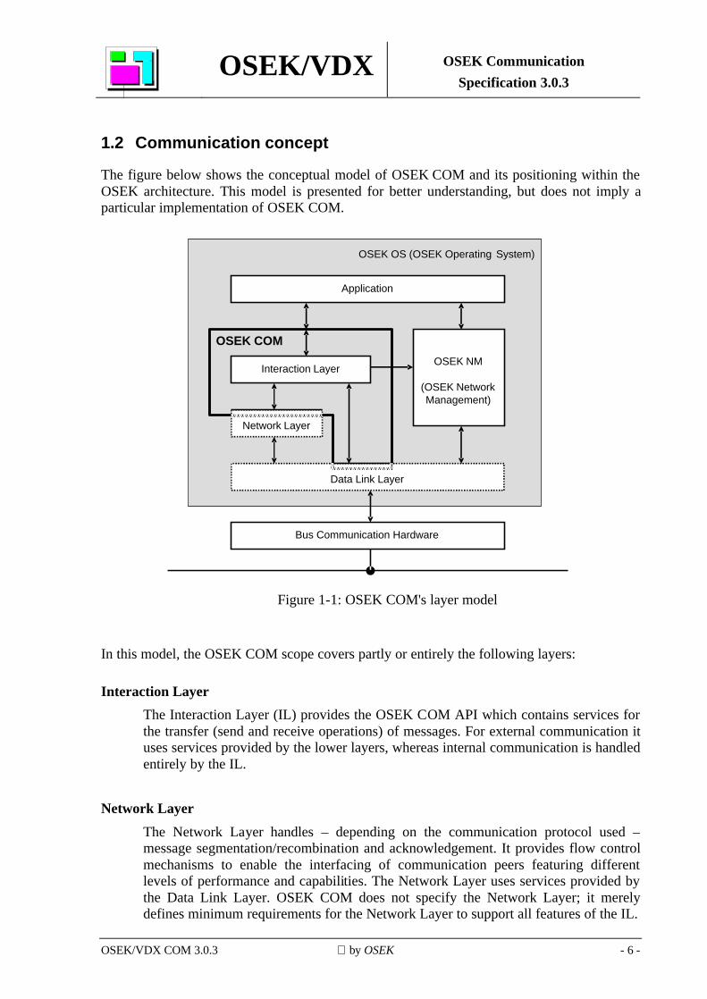
The figure below shows the conceptual model of OSEK COM and its positioning within the OSEK architecture. This model is presented for better understanding, but does not imply a particular implementation of OSEK COM.
Interaction Layer
Network Layer
Data Link Layer
OSEK NM
(OSEK NetworkManagement)
Application
OSEK OS (OSEK Operating System)
Bus Communication Hardware
OSEK COM
Figure 1-1: OSEK COM's layer model
In this model, the OSEK COM scope covers partly or entirely the following layers:
Interaction Layer The Interaction Layer (IL) provides the OSEK COM API which contains services for the transfer (send and receive operations) of messages. For external communication it uses services provided by the lower layers, whereas internal communication is handled entirely by the IL.
Network Layer The Network Layer handles – depending on the communication protocol used – message segmentation/recombination and acknowledgement. It provides flow control mechanisms to enable the interfacing of communication peers featuring different levels of performance and capabilities. The Network Layer uses services provided by the Data Link Layer. OSEK COM does not specify the Network Layer; it merely defines minimum requirements for the Network Layer to support all features of the IL.
OSEK/VDX OSEK Communication Specification 3.0.3
OSEK/VDX COM 3.0.3 by OSEK - 7 -
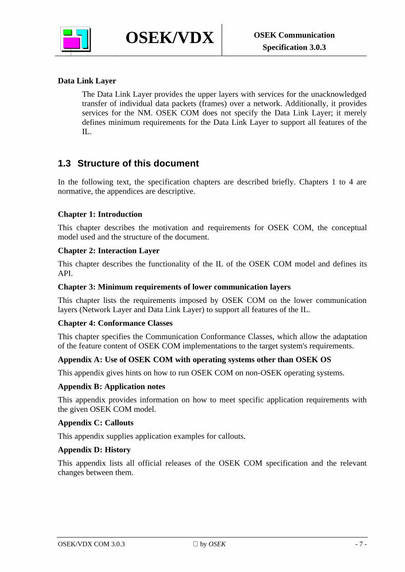
Data Link Layer The Data Link Layer provides the upper layers with services for the unacknowledged transfer of individual data packets (frames) over a network. Additionally, it provides services for the NM. OSEK COM does not specify the Data Link Layer; it merely defines minimum requirements for the Data Link Layer to support all features of the IL.
1.3 Structure of this document
In the following text, the specification chapters are described briefly. Chapters 1 to 4 are normative, the appendices are descriptive.
Chapter 1: Introduction This chapter describes the motivation and requirements for OSEK COM, the conceptual model used and the structure of the document.
Chapter 2: Interaction Layer This chapter describes the functionality of the IL of the OSEK COM model and defines its API.
Chapter 3: Minimum requirements of lower communication layers This chapter lists the requirements imposed by OSEK COM on the lower communication layers (Network Layer and Data Link Layer) to support all features of the IL.
Chapter 4: Conformance Classes This chapter specifies the Communication Conformance Classes, which allow the adaptation of the feature content of OSEK COM implementations to the target system's requirements.
Appendix A: Use of OSEK COM with operating systems other than OSEK OS This appendix gives hints on how to run OSEK COM on non-OSEK operating systems.
Appendix B: Application notes This appendix provides information on how to meet specific application requirements with the given OSEK COM model.
Appendix C: Callouts This appendix supplies application examples for callouts.
Appendix D: History This appendix lists all official releases of the OSEK COM specification and the relevant changes between them.
OSEK/VDX OSEK Communication Specification 3.0.3
OSEK/VDX COM 3.0.3 by OSEK - 8 -
2 Interaction Layer
2.1 Overview
2.1.1 Introduction
The communication in OSEK COM is based on messages1. A message contains application-specific data. Messages and message properties are configured statically via the OSEK Implementation Language (OIL). The content and usage of messages is not relevant to OSEK COM. Messages with a length of zero (zero-length messages, see Appendix B) are allowed.
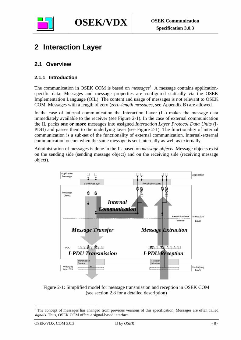
In the case of internal communication the Interaction Layer (IL) makes the message data immediately available to the receiver (see Figure 2-1). In the case of external communication the IL packs one or more messages into assigned Interaction Layer Protocol Data Units (I-PDU) and passes them to the underlying layer (see Figure 2-1). The functionality of internal communication is a sub-set of the functionality of external communication. Internal-external communication occurs when the same message is sent internally as well as externally.
Administration of messages is done in the IL based on message objects. Message objects exist on the sending side (sending message object) and on the receiving side (receiving message object).
ReceptionIndication
SendMessage ReceiveMessage
I-PDU
Message Object
Underlying Layer
Application
Interaction
Layer
internal & external
external
Application Message
Message Transfer Message Extraction
I-PDU ReceptionI-PDU Transmission
InternalCommunication
Underlying Layer PDU
TransmissionRequest
Figure 2-1: Simplified model for message transmission and reception in OSEK COM (see section 2.8 for a detailed description)
______________________________ 1 The concept of messages has changed from previous versions of this specification. Messages are often called signals. Thus, OSEK COM offers a signal-based interface.
OSEK/VDX OSEK Communication Specification 3.0.3
OSEK/VDX COM 3.0.3 by OSEK - 9 -
The data that is communicated between the IL and the underlying layer is organised into I-PDUs which contain one or more messages (see Figure 2-1). A message shall occupy contiguous bits within an I-PDU and shall not be split across I-PDUs. Within an I-PDU messages are bit-aligned. The size of a message is specified in bits. The byte order (endianess) in a CPU can differ from the network representation or from other CPUs on the network. Therefore, to provide interoperability across the network, the IL provides a conversion from the network representation to the local CPU representation and vice versa, which is statically configured on a per-message basis. The IL offers an Application Program Interface (API) to handle messages. The API provides services for initialisation, data transfer and communication management. Services transmitting messages over network are non-blocking. This implies, for example, that a service that sends a message is unable to return a final transmission status because the transfer to the network is still in progress. OSEK COM provides notification mechanisms for an application to determine the status of a transmission or reception. The functionality of the IL can be extended by callouts (section 2.8 contains a description of where callouts can be inserted).
2.1.2 Communication concept
Senders and receivers of messages are either tasks or interrupt service routines (ISRs) in an OSEK OS. Messages are sent to sending message objects and received from receiving message objects. Message objects are identified using message identifiers. Message identifiers are assigned to message objects at system generation. OSEK COM supports m:n communication. Zero or more senders can send messages to the same sending message object. Sending message objects are configured to store messages in zero or more receiving message objects for internal communication and in zero or one I-PDUs for external communication. One or more sending message objects can be configured to store messages in the same I-PDU for external communication. An I-PDU can be received by zero or more CPUs. In each CPU that receives the I-PDU, each message contained in the I-PDU is stored in zero or more receiving message objects. Zero or more receivers can receive messages from a receiving message object (see Appendix B for additional information). A receiving message object receives messages from either exactly one sending message object (internal communication) or exactly one I-PDU, or it receives no messages at all. A receiving message object can be defined as either queued or unqueued. While a message received by a message object with the property “queued” (queued message) can only be read once (the read operation removes the oldest message from the queue), a message received from a message object with the property “unqueued” (unqueued message) can be read more than once; it returns the last received value each time it is read.
The queue size for message objects with the property “queued” is specified per message object and shall not be zero. If the queue of a receiving message object is full and a new message arrives, this message is lost.
OSEK/VDX OSEK Communication Specification 3.0.3
OSEK/VDX COM 3.0.3 by OSEK - 10 -
OSEK COM is not responsible for allocating memory for the application messages, but it allows independent access to message objects for each sender and receiver. In the case of unqueued messages, an arbitrary number of receivers may receive the message. In the case of queued messages, only one receiver may receive the message. The IL guarantees that the data in the application's message copies are consistent by the following means: the IL deals with messages atomically, and application message data is only read or written during a send or receive service call.
An external message can have one of two transfer properties:
• Triggered Transfer Property: the message in the assigned I-PDU is updated and a request for the I-PDU's transmission is made.
• Pending Transfer Property: the message in the I-PDU is updated without a transmission request.
Internal messages do not have a transfer property. They are immediately routed to the receiver side. There are three transmission modes for I-PDUs:
• Direct Transmission Mode: the transmission is explicitly initiated by sending a message with Triggered Transfer Property.
• Periodic Transmission Mode: the I-PDU is transmitted repeatedly with a pre-set period.
• Mixed Transmission Mode: the I-PDU is transmitted using a combination of both the Direct and the Periodic Transmission Modes.
OSEK COM supports only static message addressing. A statically addressed message has zero or more receivers defined at system generation time, each of which receives the message whenever it is sent. A message has either a static length or its length may vary up to some statically defined maximum. Messages with a maximum length are called dynamic-length messages. OSEK COM provides a mechanism for monitoring the transmission and reception timing of messages, called Deadline Monitoring. Deadline Monitoring verifies on the sender side that the underlying layer confirms transmission requests within a defined time period and on the receiver side that periodic messages are received within a defined time period. The monitoring is performed based on I-PDUs.
The IL provides a fixed set of filter algorithms. On the sender side, a filter algorithm may be used which, depending on the message contents, discards the message. In this case, no external transmission is performed and the I-PDU is not updated. There is no filtering on the sender side for internal transmission. On the receiver side, a filter mechanism may be used per receiver in both internal and external transmission. For more details on filtering see sections 2.2.2 and 2.3.6.
OSEK/VDX OSEK Communication Specification 3.0.3
OSEK/VDX COM 3.0.3 by OSEK - 11 -
2.1.3 Configuration
The configuration of messages and of their senders and receivers shall be defined at system generation time. Messages cannot be added or deleted at run-time, nor can the packing of messages to I-PDUs be changed. This applies to all configuration elements and their attributes unless otherwise stated.
Examples for configurable items include:
• Configuration of the transfer properties of messages and the transmission modes of I-PDUs.
• Packing of the messages to I-PDUs (see section 2.4 for details).
• Usage of a queue by a receiver and the size of this queue. The configuration of single CPUs is described in OIL.
OSEK/VDX OSEK Communication Specification 3.0.3
OSEK/VDX COM 3.0.3 by OSEK - 12 -
2.2 Message reception
This section states the services and the functionality requirements of the message reception entity of the IL.
2.2.1 Message reception overview
The first few steps described in this section are applicable for external communication only.
Reception of a message starts with an indication of the delivery of its containing PDU from the underlying layer. If this indication does not yield an error, the reception was successful. In this case, an I-PDU Callout is called (if configured) and this PDU is copied into the I-PDU. In the case of unsuccessful PDU reception error indication takes place and no data is delivered to the IL. Error indication can lead to Message Reception Error notification (Notification Class 3, described in section 2.6.1).
After copying the data into the I-PDU further processing is performed separately for each contained message. If the I-PDU contains zero-length messages, these are processed last.
The Reception Deadline Monitoring takes place as described in section 2.5.1. Deadline Monitoring can invoke Message Reception Error notification (Notification Class 3, described in section 2.6.1) when the message reception deadline is missed because the I-PDU that contains the message is not received in time.
Then, the message data is unpacked from the I-PDU and, if configured, a Network-order Message Callout is called for the message. Message byte order conversion is performed to convert from network representation to the representation on the local CPU and, if configured, a CPU-order Message Callout is called for the message.
The following steps are applicable for both internal and external communication.
The filtering is applied to the message content. If the message is not filtered out, then the message data is copied into the receiver message object.
After filtering, Message Reception notification (Notification Class 1, described in section 2.6.1) is invoked as appropriate. Notification is performed per message object.
Message data are copied from message object to application messages when the application calls the ReceiveMessage or ReceiveDynamicMessage API services.
2.2.2 Reception filtering
Filtering provides a means to discard the received message when certain conditions, set by message filter, are not met for the message value. The message filter is a configurable function that filters messages out according to specific algorithms. For each message a different filtering condition can be defined through a dedicated algorithm.
Filtering is only used for messages that can be interpreted as C language unsigned integer types (characters, unsigned integers and enumerations).
OSEK/VDX OSEK Communication Specification 3.0.3
OSEK/VDX COM 3.0.3 by OSEK - 13 -
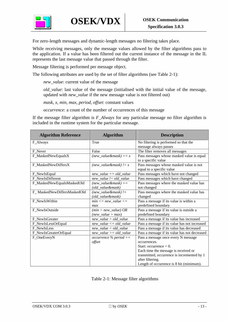
For zero-length messages and dynamic-length messages no filtering takes place.
While receiving messages, only the message values allowed by the filter algorithms pass to the application. If a value has been filtered out the current instance of the message in the IL represents the last message value that passed through the filter. Message filtering is performed per message object.
The following attributes are used by the set of filter algorithms (see Table 2-1): new_value: current value of the message
old_value: last value of the message (initialised with the initial value of the message, updated with new_value if the new message value is not filtered out)
mask, x, min, max, period, offset: constant values occurrence: a count of the number of occurrences of this message
If the message filter algorithm is F_Always for any particular message no filter algorithm is included in the runtime system for the particular message.
Algorithm Reference Algorithm Description F_Always True No filtering is performed so that the
message always passes F_Never False The filter removes all messages F_MaskedNewEqualsX (new_value&mask) == x Pass messages whose masked value is equal
to a specific value F_MaskedNewDiffersX (new_value&mask) != x Pass messages whose masked value is not
equal to a specific value F_NewIsEqual new_value == old_value Pass messages which have not changed F_NewIsDifferent new_value != old_value Pass messages which have changed F_MaskedNewEqualsMaskedOld (new_value&mask) ==
(old_value&mask) Pass messages where the masked value has not changed
F_ MaskedNewDiffersMaskedOld (new_value&mask) != (old_value&mask)
Pass messages where the masked value has changed
F_NewIsWithin min <= new_value <= max
Pass a message if its value is within a predefined boundary
F_NewIsOutside (min > new_value) OR (new_value > max)
Pass a message if its value is outside a predefined boundary
F_NewIsGreater new_value > old_value Pass a message if its value has increased F_NewIsLessOrEqual new_value <= old_value Pass a message if its value has not increased F_NewIsLess new_value < old_value Pass a message if its value has decreased F_NewIsGreaterOrEqual new_value >= old_value Pass a message if its value has not decreased F_OneEveryN occurrence % period ==
offset Pass a message once every N message occurrences. Start: occurrence = 0. Each time the message is received or transmitted, occurrence is incremented by 1 after filtering. Length of occurrence is 8 bit (minimum).
Table 2-1: Message filter algorithms
OSEK/VDX OSEK Communication Specification 3.0.3
OSEK/VDX COM 3.0.3 by OSEK - 14 -
2.2.3 Copying message data into message objects data area
Message data that are not filtered out are copied into the message object's data. One message may be delivered to one message object or more than one message object. In the latter case the message objects may be a combination of any number of queued or/and unqueued messages.
Zero-length messages do not contain data. However, the notification mechanisms work in the same way as for non zero-length messages.
2.2.4 Copying data to application messages
The message object’s data are copied to the application message by the API services ReceiveMessage or ReceiveDynamicMessage. The application provides the application message reference to the service. This transfer of information between IL and application occurs for internal, external and internal-external communication. For zero-length messages no data is copied.
2.2.5 Unqueued and queued messages
2.2.5.1 Queued message
A queued message behaves like a FIFO (first-in first-out) queue. When the queue is empty, the IL does not provide any message data to the application. When the queue is not empty and the application receives the message, then the IL provides the application with the oldest message data and removes this message data from the queue.
If new message data arrives and the queue is not full, this new message is stored in the queue. If new message data arrives and queue is full, this message is lost and the next ReceiveMessage call on this message object returns the information that a message has been lost.
Note that for m:n communication a separate queue is supported for each receiver and that messages from these queues are consumed independently.
OSEK/VDX OSEK Communication Specification 3.0.3
OSEK/VDX COM 3.0.3 by OSEK - 15 -
2.2.5.2 Unqueued message
Unqueued messages do not use the FIFO mechanism. The application does not consume the message during reception of message data – instead, a message may be read multiple times by an application once the IL has received it. If no message has been received since the start of the IL, then the application receives the message value set at initialisation. Unqueued messages are overwritten by newly arrived messages.
OSEK/VDX OSEK Communication Specification 3.0.3
OSEK/VDX COM 3.0.3 by OSEK - 16 -
2.3 Message transmission
2.3.1 Message transmission overview
Sending a message requires the transfer of the application message to the I-PDU (external communication) and/or the receiving message object(s) (internal communication).
A message that is transferred can be stored in zero or more message objects for internal receivers and in zero or one I-PDU for external communication.
The application message is transferred upon calling a specific API service (SendMessage, SendDynamicMessage or SendZeroMessage).
When the API service is called for internal communication, the message is directly handed to the receiving part of the IL (see section 2.2) for further processing.
The following description is for external communication only. For external communication, filtering on the sending side is performed. If the message is discarded, no further action takes place. No filtering takes place on zero-length messages or dynamic-length messages.
Thereafter, if configured, the CPU-order Message Callout is called, byte order conversion is performed, the Network-order Message Callout is called and the message is stored in the I-PDU. The transfer of information between the application and IL may use any of the applicable transfer properties of messages: Triggered or Pending. Transmission of messages via the underlying layers takes place based on I-PDUs. Transmission of I-PDUs may use any of the applicable transmission modes of I-PDUs: Direct, Periodic or Mixed.
More than one message may be stored in an I-PDU. However, only the last message in an I-PDU may be a dynamic-length message. Static-length messages may overlap each other, but it is not allowed for any message to overlap a dynamic-length message. Two messages are defined as overlapping if they have at least one I-PDU bit in common.
The moment when transmission is initiated, the I-PDU Callout is called. The user can be notified if the I-PDU is transferred successfully (by confirmation from the underlying layer not containing an error) or not (by confirmation from the underlying layer containing an error, or by a time-out).
OSEK/VDX OSEK Communication Specification 3.0.3
OSEK/VDX COM 3.0.3 by OSEK - 17 -
2.3.2 Transfer of internal messages
Internal messages do not have transfer properties because the transfer is always executed in the same way. The IL routes internal messages directly to the receiving part of the IL (see section 2.2) for further processing. The application is responsible for requesting each transfer of an internal message using the SendMessage or SendZeroMessage API service.
No data transfer takes place for zero-length messages.
2.3.3 Transfer properties for external communication
OSEK COM supports two different transfer properties for the transfer of external messages from the application to the I-PDU: Triggered and Pending. The application is responsible for requesting each transfer of a message to the IL, using the SendMessage, SendDynamicMessage or SendZeroMessage API services. Depending on filtering (for SendMessage only), the message can be discarded. If the message is not discarded, the IL stores it in the corresponding I-PDU. No data transfer takes place for zero-length messages.
Zero-length messages can only have Triggered Transfer Property. Even if no transmission has taken place since the last call to SendMessage or SendDynamicMessage, the I-PDU is updated.
2.3.3.1 Triggered Transfer Property
The Triggered Transfer Property causes immediate transmission of the I-PDU, except if Periodic Transmission Mode is defined for the I-PDU.
2.3.3.2 Pending Transfer Property
The Pending Transfer Property does not cause transmission of the I-PDU.
2.3.4 Transmission modes
OSEK COM supports three different transmission modes for the transmission of I-PDUs via the underlying layers: Direct, Periodic and Mixed.
OSEK/VDX OSEK Communication Specification 3.0.3
OSEK/VDX COM 3.0.3 by OSEK - 18 -
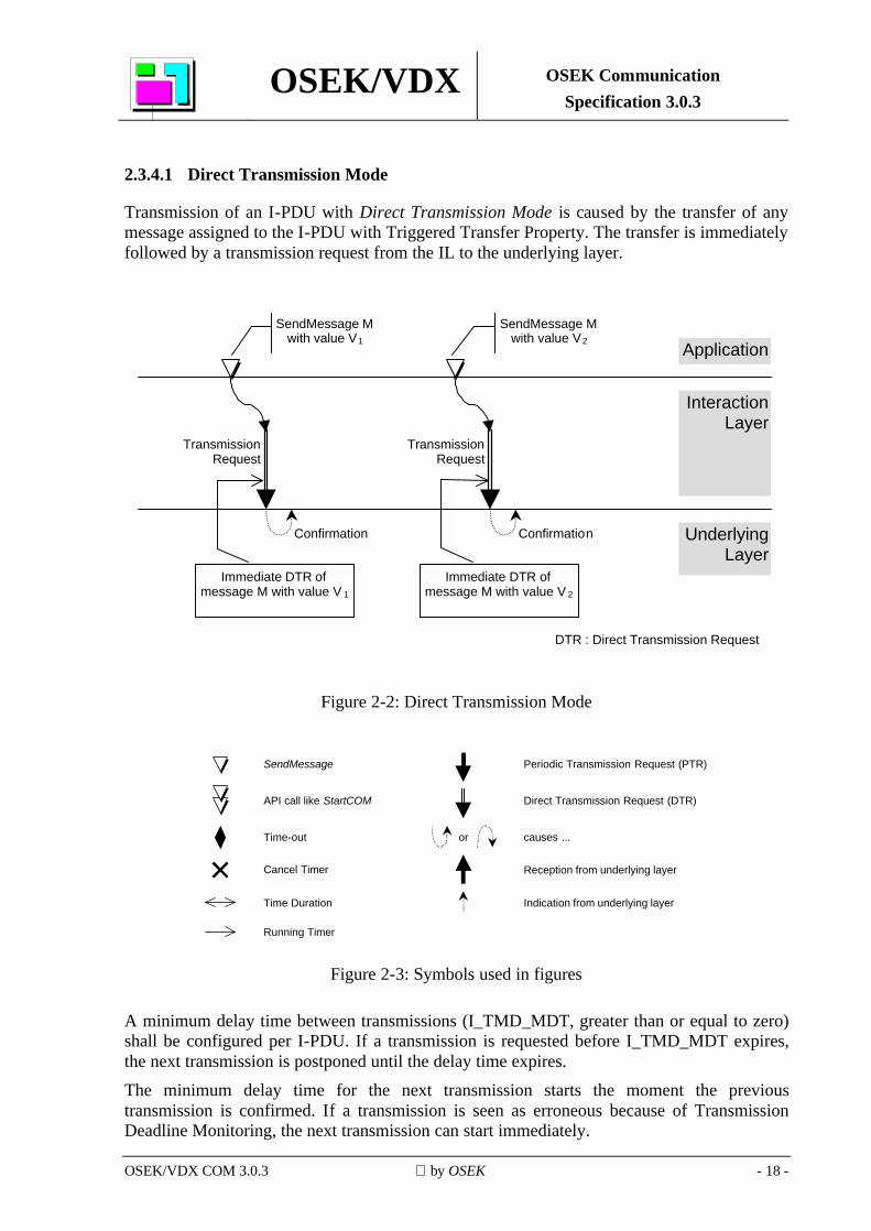
2.3.4.1 Direct Transmission Mode
Transmission of an I-PDU with Direct Transmission Mode is caused by the transfer of any message assigned to the I-PDU with Triggered Transfer Property. The transfer is immediately followed by a transmission request from the IL to the underlying layer.
Application
Interaction Layer
Underlying Layer
DTR : Direct Transmission Request
Immediate DTR of message M with value V 1
SendMessage M with value V1
Confirmation
TransmissionRequest
Immediate DTR of message M with value V 2
SendMessage M with value V2
Confirmation
TransmissionRequest
Figure 2-2: Direct Transmission Mode
SendMessage
Time-out
Cancel Timer
Time Duration
API call like StartCOM
Periodic Transmission Request (PTR)
Direct Transmission Request (DTR)
causes ...
Running Timer
or
Reception from underlying layer
Indication from underlying layer
Figure 2-3: Symbols used in figures
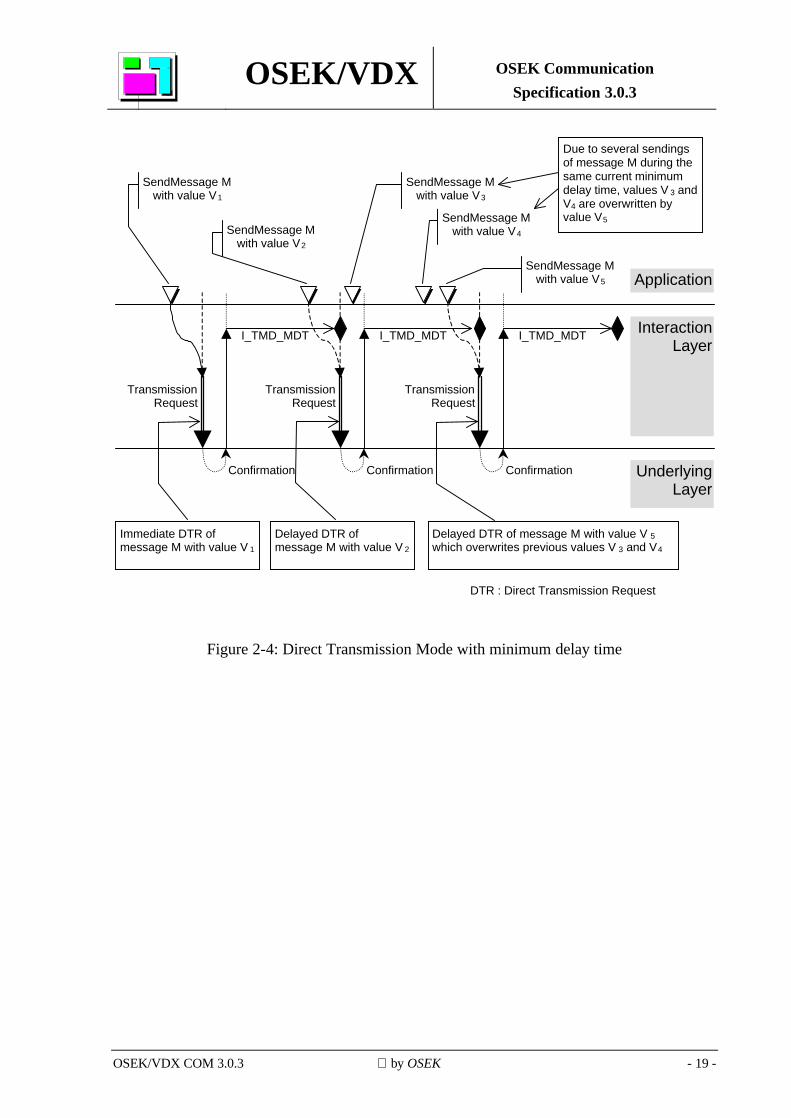
A minimum delay time between transmissions (I_TMD_MDT, greater than or equal to zero) shall be configured per I-PDU. If a transmission is requested before I_TMD_MDT expires, the next transmission is postponed until the delay time expires. The minimum delay time for the next transmission starts the moment the previous transmission is confirmed. If a transmission is seen as erroneous because of Transmission Deadline Monitoring, the next transmission can start immediately.
OSEK/VDX OSEK Communication Specification 3.0.3
OSEK/VDX COM 3.0.3 by OSEK - 19 -
Application
InteractionLayer
UnderlyingLayer
DTR : Direct Transmission Request
Immediate DTR ofmessage M with value V 1
SendMessage Mwith value V1
Confirmation
TransmissionRequest
Delayed DTR ofmessage M with value V 2
SendMessage Mwith value V2
Confirmation
TransmissionRequest
I_TMD_MDT I_TMD_MDT
Delayed DTR of message M with value V 5which overwrites previous values V 3 and V4
SendMessage Mwith value V5
Confirmation
TransmissionRequest
I_TMD_MDT
SendMessage Mwith value V4
SendMessage Mwith value V3
Due to several sendingsof message M during thesame current minimumdelay time, values V 3 andV4 are overwritten byvalue V5
Figure 2-4: Direct Transmission Mode with minimum delay time
OSEK/VDX OSEK Communication Specification 3.0.3
OSEK/VDX COM 3.0.3 by OSEK - 20 -
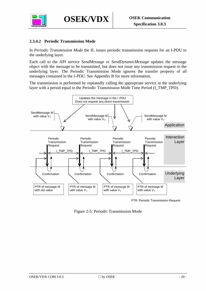
2.3.4.2 Periodic Transmission Mode
In Periodic Transmission Mode the IL issues periodic transmission requests for an I-PDU to the underlying layer.
Each call to the API service SendMessage or SendDynamicMessage updates the message object with the message to be transmitted, but does not issue any transmission request to the underlying layer. The Periodic Transmission Mode ignores the transfer property of all messages contained in the I-PDU. See Appendix B for more information.
The transmission is performed by repeatedly calling the appropriate service in the underlying layer with a period equal to the Periodic Transmission Mode Time Period (I_TMP_TPD).
I_TMP_TPD
Periodic Transmission Request
Confirmation
I_TMP_TPD
Confirmation
I_TMP_TPD
Confirmation Confirmation
Periodic Transmission Request
Periodic Transmission Request
Updates the message in the I -PDU Does not request any direct transmission
SendMessage M with value V1 SendMessage M
with value V2 SendMessage M
with value V3
PTR of message M with value V1
PTR of message M with value V3
PTR of message M with value V1
PTR of message M with old value
PTR: Periodic Transmission Request
Application
Interaction Layer
Underlying Layer
Periodic Transmission Request
Figure 2-5: Periodic Transmission Mode
OSEK/VDX OSEK Communication Specification 3.0.3
OSEK/VDX COM 3.0.3 by OSEK - 21 -
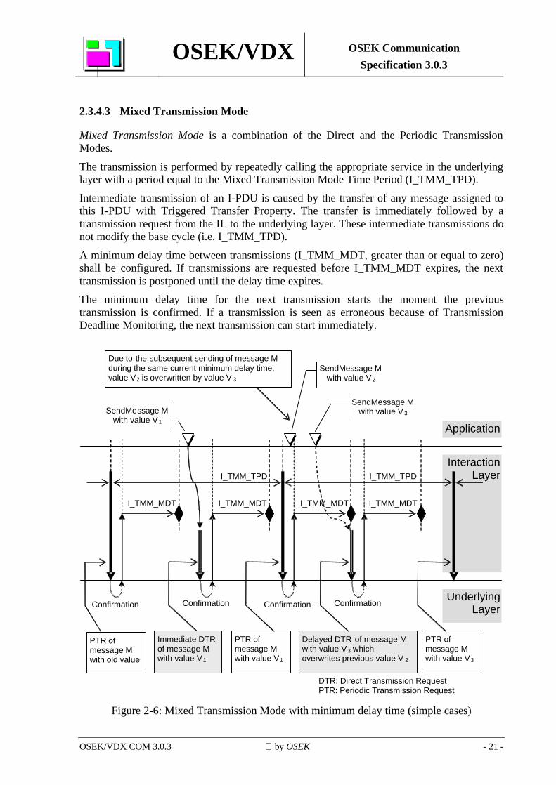
2.3.4.3 Mixed Transmission Mode
Mixed Transmission Mode is a combination of the Direct and the Periodic Transmission Modes.
The transmission is performed by repeatedly calling the appropriate service in the underlying layer with a period equal to the Mixed Transmission Mode Time Period (I_TMM_TPD).
Intermediate transmission of an I-PDU is caused by the transfer of any message assigned to this I-PDU with Triggered Transfer Property. The transfer is immediately followed by a transmission request from the IL to the underlying layer. These intermediate transmissions do not modify the base cycle (i.e. I_TMM_TPD).
A minimum delay time between transmissions (I_TMM_MDT, greater than or equal to zero) shall be configured. If transmissions are requested before I_TMM_MDT expires, the next transmission is postponed until the delay time expires. The minimum delay time for the next transmission starts the moment the previous transmission is confirmed. If a transmission is seen as erroneous because of Transmission Deadline Monitoring, the next transmission can start immediately.
Application
Interaction Layer
Underlying Layer
DTR: Direct Transmission Request PTR: Periodic Transmission Request
PTR of message M with old value
SendMessage M with value V1
Confirmation
SendMessage M with value V2
I_TMM_MDT
Delayed DTR of message M with value V3 which overwrites previous value V 2
SendMessage M with value V 3
Due to the subsequent sending of message M during the same current minimum delay time, value V2 is overwritten by value V 3
I_TMM_MDT
Confirmation
I_TMM_MDT
Confirmation Confirmation
I_TMM_MDT
Immediate DTR of message M with value V1
PTR of message M with value V1
PTR of message M with value V3
I_TMM_TPD I_TMM_TPD
Figure 2-6: Mixed Transmission Mode with minimum delay time (simple cases)
OSEK/VDX OSEK Communication Specification 3.0.3
OSEK/VDX COM 3.0.3 by OSEK - 22 -
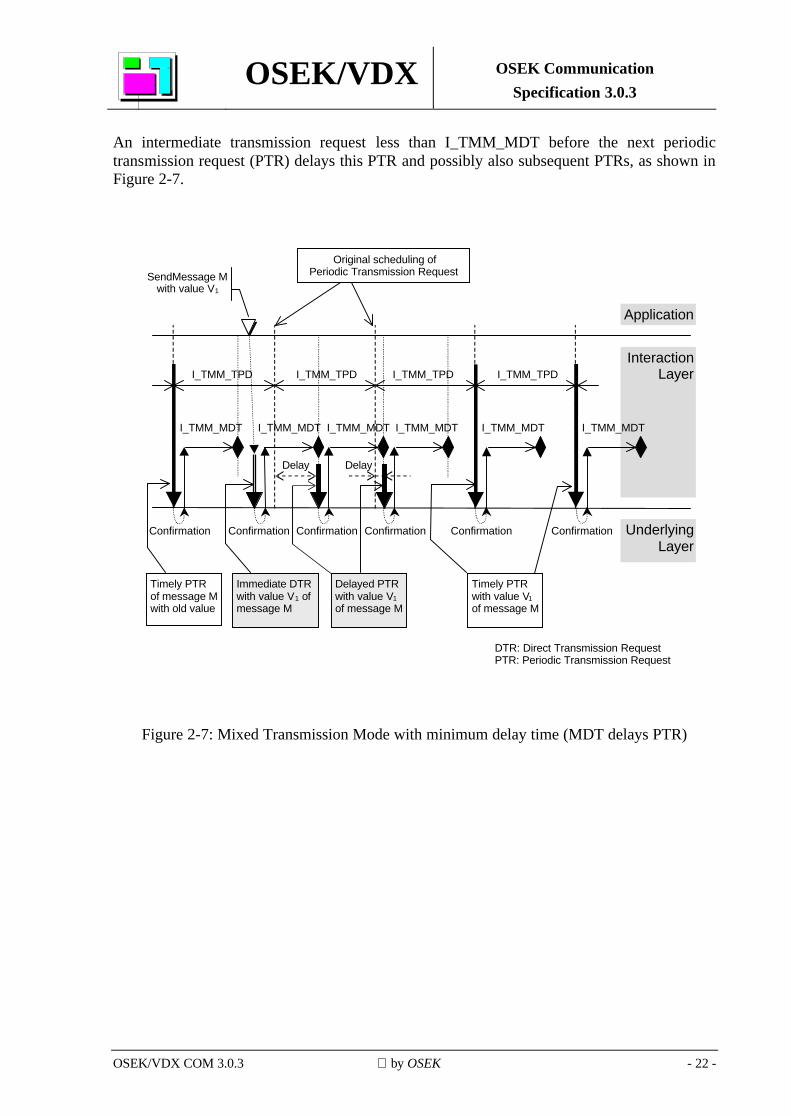
An intermediate transmission request less than I_TMM_MDT before the next periodic transmission request (PTR) delays this PTR and possibly also subsequent PTRs, as shown in Figure 2-7.
InteractionLayerI_TMM_TPD
Delay
I_TMM_TPDI_TMM_TPD I_TMM_TPD
Original scheduling ofPeriodic Transmission Request
I_TMM_MDTI_TMM_MDT I_TMM_MDT
Delay
I_TMM_MDT I_TMM_MDT
Application
UnderlyingLayer
DTR: Direct Transmission RequestPTR: Periodic Transmission Request
Timely PTRof message Mwith old value
SendMessage Mwith value V1
Immediate DTRwith value V1 ofmessage M
Delayed PTRwith value V1of message M
Timely PTRwith value V1of message M
I_TMM_MDT
ConfirmationConfirmation ConfirmationConfirmation Confirmation Confirmation
Figure 2-7: Mixed Transmission Mode with minimum delay time (MDT delays PTR)
OSEK/VDX OSEK Communication Specification 3.0.3
OSEK/VDX COM 3.0.3 by OSEK - 23 -
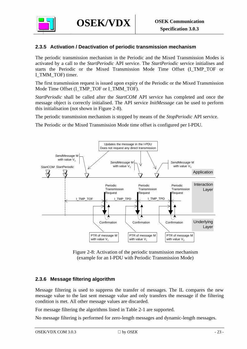
2.3.5 Activation / Deactivation of periodic transmission mechanism
The periodic transmission mechanism in the Periodic and the Mixed Transmission Modes is activated by a call to the StartPeriodic API service. The StartPeriodic service initialises and starts the Periodic or the Mixed Transmission Mode Time Offset (I_TMP_TOF or I_TMM_TOF) timer.
The first transmission request is issued upon expiry of the Periodic or the Mixed Transmission Mode Time Offset (I_TMP_TOF or I_TMM_TOF).
StartPeriodic shall be called after the StartCOM API service has completed and once the message object is correctly initialised. The API service InitMessage can be used to perform this initialisation (not shown in Figure 2-8). The periodic transmission mechanism is stopped by means of the StopPeriodic API service.
The Periodic or the Mixed Transmission Mode time offset is configured per I-PDU.
I_TMP_TPD
Confirmation
I_TMP_TPD
Confirmation Confirmation
PeriodicTransmissionRequest
PeriodicTransmissionRequest
SendMessage Mwith value V1
SendMessage Mwith value V2
SendMessage Mwith value V3
PTR of message Mwith value V1
PTR of message Mwith value V3
PTR of message Mwith value V1
Application
InteractionLayer
UnderlyingLayer
StartPeriodicStartCOM
I_TMP_TOF
PeriodicTransmissionRequest
Updates the message in the I-PDUDoes not request any direct transmission
Figure 2-8: Activation of the periodic transmission mechanism
(example for an I-PDU with Periodic Transmission Mode)
2.3.6 Message filtering algorithm
Message filtering is used to suppress the transfer of messages. The IL compares the new message value to the last sent message value and only transfers the message if the filtering condition is met. All other message values are discarded. For message filtering the algorithms listed in Table 2-1 are supported.
No message filtering is performed for zero-length messages and dynamic-length messages.
OSEK/VDX OSEK Communication Specification 3.0.3
OSEK/VDX COM 3.0.3 by OSEK - 24 -
2.4 Byte order conversion and message interpretation
The IL is responsible for the byte order conversion between the local CPU and the underlying layers and vice versa. Byte order conversion (big-endian to little-endian and vice versa) takes place on the sender side before messages are stored in the I-PDU and on the receiver side when they are retrieved from the I-PDU. Messages are configured either to remain untouched, or to be interpreted as C unsigned integer types and converted. No byte order conversion takes place on internal messages and dynamic-length messages. The IL does not prescribe the byte order used in I-PDUs: different messages in the same I-PDU may have different byte order. On the sender side, for messages which are interpreted as integers, the most significant bits are truncated, if necessary. On the receiver side, for messages which are interpreted as integers, the most significant bits are filled with 0, if necessary. Dynamic-length messages are always interpreted as byte arrays.
2.4.1 Bit and byte numbering in I-PDUs and messages
An I-PDU is a sequence of bytes numbered from 0 upwards. Within an I-PDU byte, bits are numbered from 0 upwards with bit 0 being the least significant bit.
A message, at the moment it is packed to the I-PDU, is regarded as a sequence of bits numbered from 0 upwards with bit 0 being the least significant bit.
I-PDU bits are numbered counting from 0 upwards from bit 0 of byte 0 of the sequence of bytes constituting the I-PDU.
2.4.2 Little-endian byte order
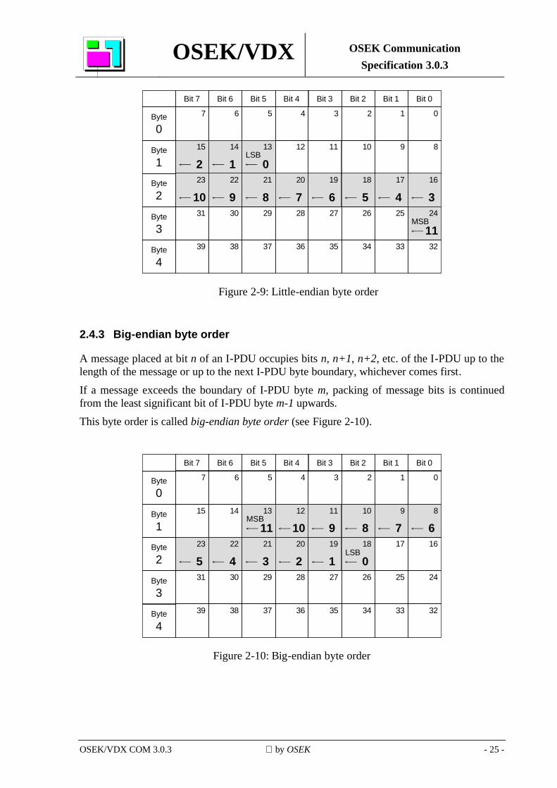
A message placed at bit n of an I-PDU occupies bits n, n+1, n+2, etc. of the I-PDU up to the length of the message.
The least significant bit of the message (LSB, message bit 0) is stored in I-PDU bit n. The most significant bit of the message (MSB, message bit i) is stored in I-PDU bit n+i. This byte order is called little-endian byte order (see Figure 2-9).
OSEK/VDX OSEK Communication Specification 3.0.3
OSEK/VDX COM 3.0.3 by OSEK - 25 -
1234567
15
214
113
0
0
101112 9 8
23
1022
921
820
719
618
517
416
324
1125262728293031
33343536373839 32
LSB
MSB
Byte0
Byte1
Byte2
Byte3
Byte4
Bit 7 Bit 6 Bit 5 Bit 4 Bit 3 Bit 2 Bit 1 Bit 0
Figure 2-9: Little-endian byte order
2.4.3 Big-endian byte order
A message placed at bit n of an I-PDU occupies bits n, n+1, n+2, etc. of the I-PDU up to the length of the message or up to the next I-PDU byte boundary, whichever comes first. If a message exceeds the boundary of I-PDU byte m, packing of message bits is continued from the least significant bit of I-PDU byte m-1 upwards. This byte order is called big-endian byte order (see Figure 2-10).
1234567
15 14 13
0
101112 9 8
23
1022
921
820
719
618
517
416
324
11
25262728293031
33343536373839 32
MSB
Byte0
Byte1
Byte2
Byte3
Byte4
Bit 7 Bit 6 Bit 5 Bit 4 Bit 3 Bit 2 Bit 1 Bit 0
2 1 0LSB
Figure 2-10: Big-endian byte order
OSEK/VDX OSEK Communication Specification 3.0.3
OSEK/VDX COM 3.0.3 by OSEK - 26 -
2.5 Deadline monitoring
2.5.1 Reception Deadline Monitoring
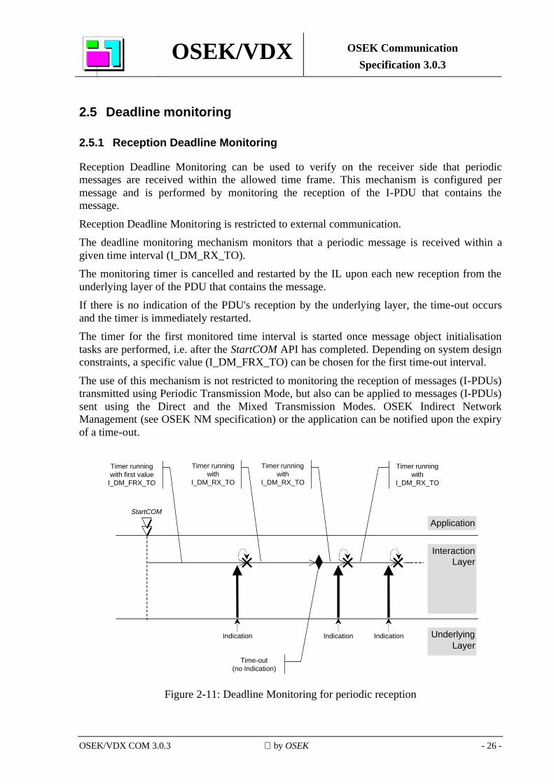
Reception Deadline Monitoring can be used to verify on the receiver side that periodic messages are received within the allowed time frame. This mechanism is configured per message and is performed by monitoring the reception of the I-PDU that contains the message.
Reception Deadline Monitoring is restricted to external communication. The deadline monitoring mechanism monitors that a periodic message is received within a given time interval (I_DM_RX_TO). The monitoring timer is cancelled and restarted by the IL upon each new reception from the underlying layer of the PDU that contains the message. If there is no indication of the PDU's reception by the underlying layer, the time-out occurs and the timer is immediately restarted. The timer for the first monitored time interval is started once message object initialisation tasks are performed, i.e. after the StartCOM API has completed. Depending on system design constraints, a specific value (I_DM_FRX_TO) can be chosen for the first time-out interval.
The use of this mechanism is not restricted to monitoring the reception of messages (I-PDUs) transmitted using Periodic Transmission Mode, but also can be applied to messages (I-PDUs) sent using the Direct and the Mixed Transmission Modes. OSEK Indirect Network Management (see OSEK NM specification) or the application can be notified upon the expiry of a time-out.
Application
InteractionLayer
UnderlyingLayer
StartCOM
Indication Indication Indication
Time-out(no Indication)
Timer runningwith first value
I_DM_FRX_TO
Timer runningwith
I_DM_RX_TO
Timer runningwith
I_DM_RX_TO
Timer runningwith
I_DM_RX_TO
Figure 2-11: Deadline Monitoring for periodic reception
OSEK/VDX OSEK Communication Specification 3.0.3
OSEK/VDX COM 3.0.3 by OSEK - 27 -
2.5.2 Transmission Deadline Monitoring
This section of the specification defines mechanisms for monitoring the transmission of messages.
Deadline Monitoring on the sender side can be used to verify that transmission requests (periodic or otherwise) are followed by transmissions on the network within a given time frame. Whether Transmission Deadline Monitoring is to be performed can be configured separately for each message. However, the IL performs Transmission Deadline Monitoring per I-PDU. Therefore the time-out period is a property of the I-PDU.
For messages using Triggered Transfer Property, transmission monitoring is available for any transmission mode. For messages using Pending Transfer Property, transmission monitoring is available for Periodic Transmission Mode and the periodic part of Mixed Transmission Mode.
2.5.2.1 Direct Transmission Mode
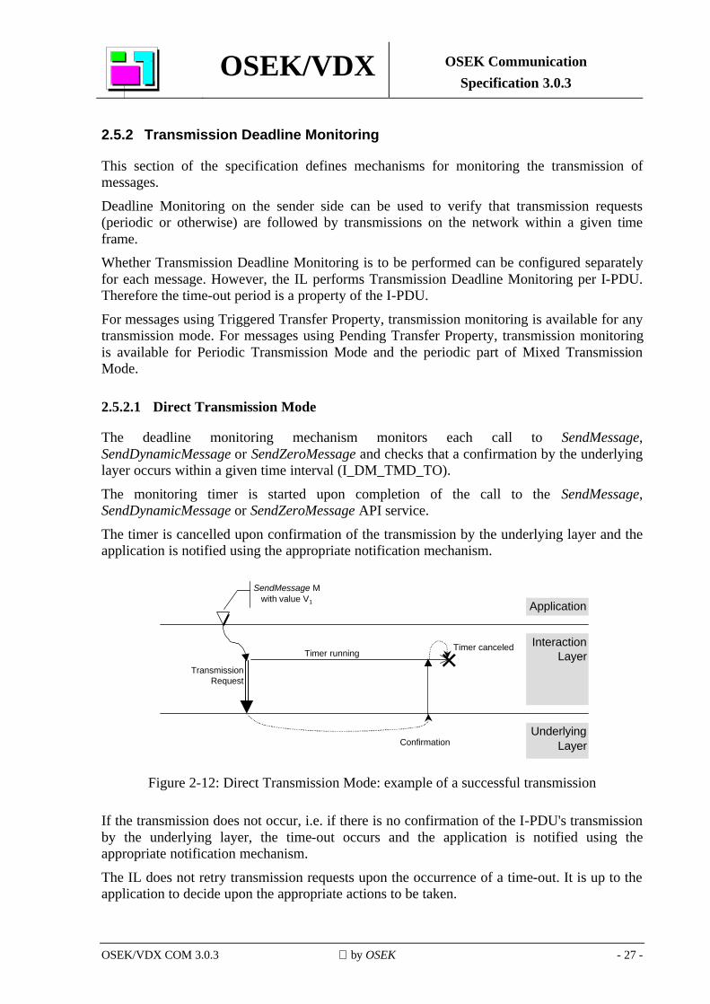
The deadline monitoring mechanism monitors each call to SendMessage, SendDynamicMessage or SendZeroMessage and checks that a confirmation by the underlying layer occurs within a given time interval (I_DM_TMD_TO).
The monitoring timer is started upon completion of the call to the SendMessage, SendDynamicMessage or SendZeroMessage API service.
The timer is cancelled upon confirmation of the transmission by the underlying layer and the application is notified using the appropriate notification mechanism.
Application
InteractionLayer
UnderlyingLayer
SendMessage Mwith value V1
Confirmation
TransmissionRequest
Timer runningTimer canceled
Figure 2-12: Direct Transmission Mode: example of a successful transmission
If the transmission does not occur, i.e. if there is no confirmation of the I-PDU's transmission by the underlying layer, the time-out occurs and the application is notified using the appropriate notification mechanism.
The IL does not retry transmission requests upon the occurrence of a time-out. It is up to the application to decide upon the appropriate actions to be taken.
OSEK/VDX OSEK Communication Specification 3.0.3
OSEK/VDX COM 3.0.3 by OSEK - 28 -
Application
InteractionLayer
UnderlyingLayer
SendMessage Mwith value V1
TransmissionRequest
Timer running
Time-out
Figure 2-13: Direct Transmission Mode: example of a failed transmission
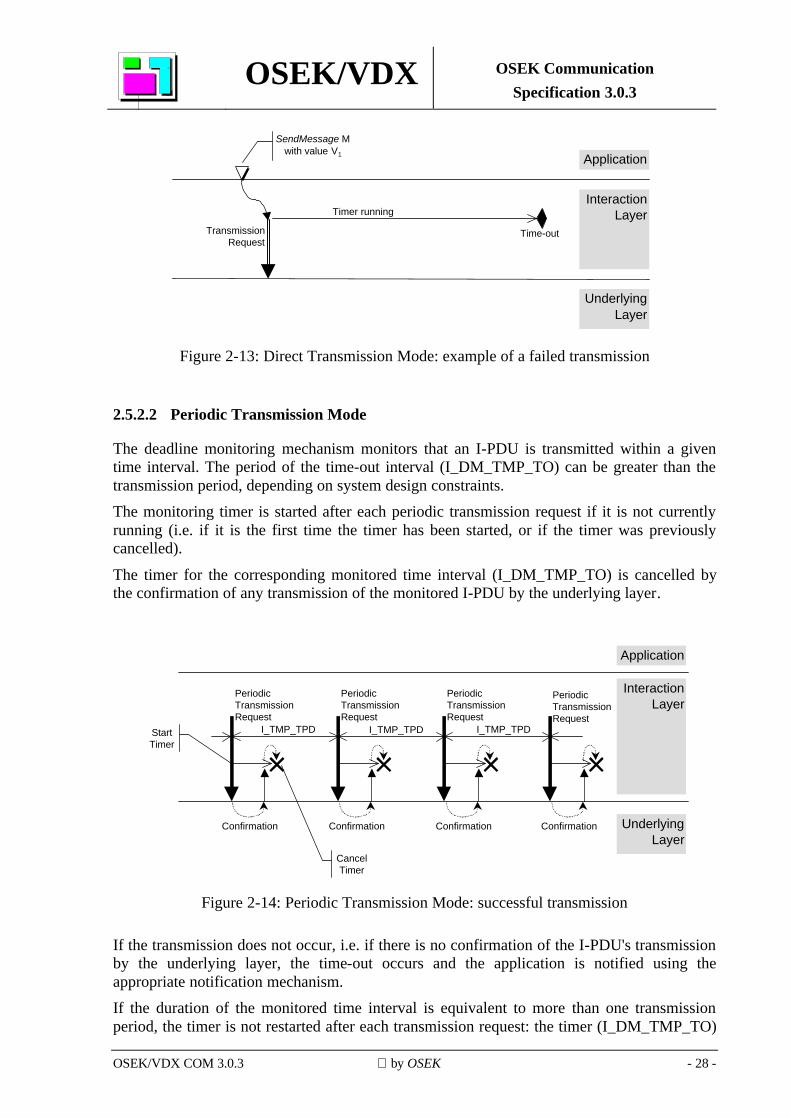
2.5.2.2 Periodic Transmission Mode
The deadline monitoring mechanism monitors that an I-PDU is transmitted within a given time interval. The period of the time-out interval (I_DM_TMP_TO) can be greater than the transmission period, depending on system design constraints. The monitoring timer is started after each periodic transmission request if it is not currently running (i.e. if it is the first time the timer has been started, or if the timer was previously cancelled).
The timer for the corresponding monitored time interval (I_DM_TMP_TO) is cancelled by the confirmation of any transmission of the monitored I-PDU by the underlying layer.
I_TMP_TPD
PeriodicTransmissionRequest
Confirmation
I_TMP_TPD I_TMP_TPD
PeriodicTransmissionRequest
PeriodicTransmissionRequest
Application
InteractionLayer
UnderlyingLayer
PeriodicTransmissionRequest
StartTimer
CancelTimer
Confirmation Confirmation Confirmation
Figure 2-14: Periodic Transmission Mode: successful transmission
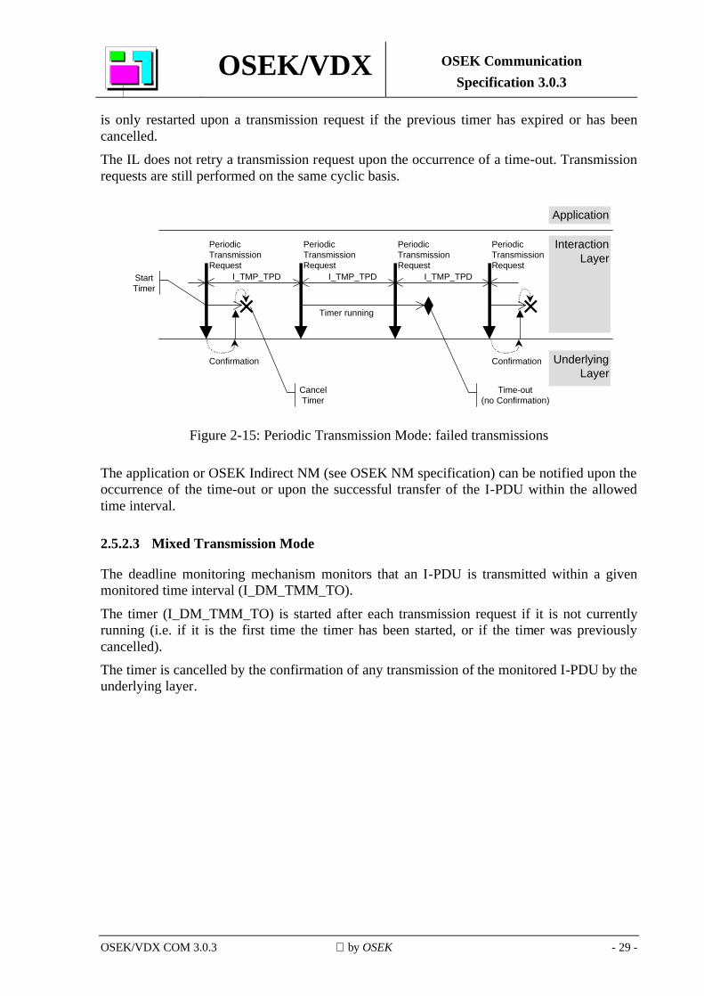
If the transmission does not occur, i.e. if there is no confirmation of the I-PDU's transmission by the underlying layer, the time-out occurs and the application is notified using the appropriate notification mechanism. If the duration of the monitored time interval is equivalent to more than one transmission period, the timer is not restarted after each transmission request: the timer (I_DM_TMP_TO)
OSEK/VDX OSEK Communication Specification 3.0.3
OSEK/VDX COM 3.0.3 by OSEK - 29 -
is only restarted upon a transmission request if the previous timer has expired or has been cancelled. The IL does not retry a transmission request upon the occurrence of a time-out. Transmission requests are still performed on the same cyclic basis.
Time-out(no Confirmation)
I_TMP_TPD
PeriodicTransmissionRequest
Confirmation
I_TMP_TPD I_TMP_TPD
PeriodicTransmissionRequest
PeriodicTransmissionRequest
Application
InteractionLayer
UnderlyingLayer
PeriodicTransmissionRequest
StartTimer
CancelTimer
Confirmation
Timer running
Figure 2-15: Periodic Transmission Mode: failed transmissions
The application or OSEK Indirect NM (see OSEK NM specification) can be notified upon the occurrence of the time-out or upon the successful transfer of the I-PDU within the allowed time interval.
2.5.2.3 Mixed Transmission Mode
The deadline monitoring mechanism monitors that an I-PDU is transmitted within a given monitored time interval (I_DM_TMM_TO).
The timer (I_DM_TMM_TO) is started after each transmission request if it is not currently running (i.e. if it is the first time the timer has been started, or if the timer was previously cancelled). The timer is cancelled by the confirmation of any transmission of the monitored I-PDU by the underlying layer.
OSEK/VDX OSEK Communication Specification 3.0.3
OSEK/VDX COM 3.0.3 by OSEK - 30 -
I_TMP_TPD
PeriodicTransmissionRequest
Confirmation
I_TMP_TPD
DirectTransmissionRequest
PeriodicTransmissionRequest
Application
InteractionLayer
UnderlyingLayer
StartTimer
CancelTimer
SendMessage Mwith value V1
ConfirmationConfirmation
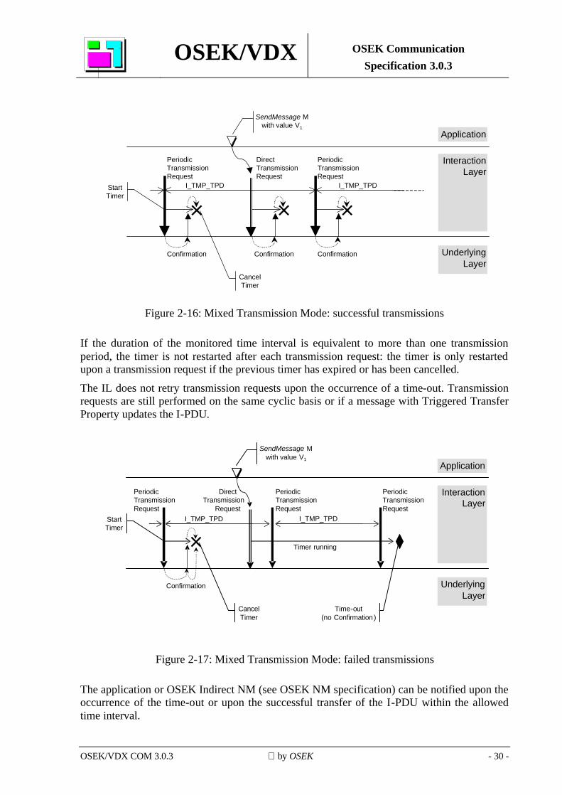
Figure 2-16: Mixed Transmission Mode: successful transmissions
If the duration of the monitored time interval is equivalent to more than one transmission period, the timer is not restarted after each transmission request: the timer is only restarted upon a transmission request if the previous timer has expired or has been cancelled.
The IL does not retry transmission requests upon the occurrence of a time-out. Transmission requests are still performed on the same cyclic basis or if a message with Triggered Transfer Property updates the I-PDU.
Time-out(no Confirmation )
I_TMP_TPD
PeriodicTransmissionRequest
Confirmation
I_TMP_TPD
PeriodicTransmissionRequest
Application
Interaction Layer
Underlying Layer
StartTimer
CancelTimer
DirectTransmission
Request
SendMessage M with value V1
PeriodicTransmissionRequest
Timer running
Figure 2-17: Mixed Transmission Mode: failed transmissions
The application or OSEK Indirect NM (see OSEK NM specification) can be notified upon the occurrence of the time-out or upon the successful transfer of the I-PDU within the allowed time interval.
OSEK/VDX OSEK Communication Specification 3.0.3
OSEK/VDX COM 3.0.3 by OSEK - 31 -
2.6 Notification
This section defines the notification mechanisms available to the application to determine the final status of a previously called send or receive operation. The application is notified as soon as a specific event has occurred; e.g. the user does not need to call a specific OSEK COM API service in advance to ensure that the notification scheme is active.
Notification is always a conditional notification. This means that, in the case of filtering, notification is only performed if the (transmitted or received) data is not discarded by the filtering mechanism. Likewise, notification on the receiver side is not performed if a queued message is discarded because of a buffer overflow condition.
Notification is configured per message object on both the sender and receiver sides. It is performed by monitoring the I-PDU that contains the message for transmission, and by monitoring the message object for reception.
2.6.1 Notification classes
OSEK COM supports four notification classes for message transmission and reception. Classes 1 and 3 notify the receiver of a message whereas classes 2 and 4 notify the sender of a message.
All classes are supported for external communication. For internal communication, only class 1 is supported.
1. Notification Class 1: Message Reception The configured notification mechanism is invoked immediately after the message has been stored in the receiving message object.
2. Notification Class 2: Message Transmission
The configured notification mechanism is invoked immediately after successful transmission of the I-PDU containing the message.
3. Notification Class 3: Message Reception Error The configured notification mechanism is invoked immediately after a message reception error has been detected either by the deadline monitoring mechanism or via an error code provided by the indication service of the underlying layer.
4. Notification Class 4: Message Transmission Error The configured notification mechanism is invoked immediately after a message transmission error has been detected either by the deadline monitoring mechanism or via an error code provided by the confirmation service of the underlying layer.
OSEK/VDX OSEK Communication Specification 3.0.3
OSEK/VDX COM 3.0.3 by OSEK - 32 -
2.6.2 Notification mechanisms
The following notification mechanisms are provided2: 1. Callback routine
The IL calls a callback routine provided by the application. 2. Flag
The IL sets a flag that can be checked by the application by means of the ReadFlag API service (ReadFlag returns COM_TRUE if the flag is set, otherwise it returns COM_FALSE). Resetting the flag is performed by the application by means of the ResetFlag API service. Additionally, calls to ReceiveMessage and ReceiveDynamicMessage reset flags defined for Notification Classes 1 and 3 and calls to SendMessage, SendDynamicMessage and SendZeroMessage reset flags defined for Notification Classes 2 and 4.
3. Task The IL activates an application task.
4. Event The IL sets an event for an application task.
Only one type of notification mechanism can be defined for a given sender or receiver message object and a given notification class. All notification mechanisms are available for all notification classes.
Except for StartCOM and StopCOM, the use of all OSEK COM API functions is allowed in callback routines. The user shall take care of problems which can arise because of nesting of callbacks (stack size etc.).
2.6.3 Interface for callback routines
Within the application, a callback routine is defined according to the following template: COMCallback(CallbackRoutineName) { }
No parameters are passed to a callback routine and they do not have a return value. A callback routine runs either on interrupt level or on task level. Thus, the OS restrictions of usage of system functions for interrupt service routines as well as for tasks apply.
______________________________ 2 An additional notification mechanism is supported for indirect NM, see section 2.9.1.
OSEK/VDX OSEK Communication Specification 3.0.3
OSEK/VDX COM 3.0.3 by OSEK - 33 -
2.7 Communication system management
2.7.1 Initialisation / Shutdown
The start-up of a distributed system depends heavily on the communication protocol used and can only be specified with detailed knowledge of this protocol. Therefore, the description of the communication protocol specific API is not defined within OSEK COM. It is assumed that all underlying layers are correctly started and the necessary communication protocols are running. OSEK COM provides the following services to start up and shut down communication:
• StartCOM: This service initialises internal OSEK COM data areas, calls message initialisation routines and starts the OSEK COM module.
• StopCOM: This service is used to terminate a session of OSEK COM and release resources where applicable.
• StartPeriodic and StopPeriodic : These services start or stop the periodic transmission of all messages using the Periodic or the Mixed Transmission Mode. It is sometimes useful to suspend periodic activity without necessarily closing down the whole of OSEK COM. StartCOM does not automatically enable periodic transmission.
StopCOM terminates periodic transmission.
• InitMessage: This service allows the application to initialise messages with arbitrary values.
Once the kernel has started, an application calls StartCOM. This service is intended to allocate and initialise system resources used by the OSEK COM module. If configured in OIL, StartCOM calls a user-supplied function StartCOMExtension. For queued messages StartCOM initialises the number of received messages to 0.
Unqueued messages can be initialised in three ways: no initial value specified in the OIL file, initial value specified in the OIL file and explicitly via the InitMessage call.
• If a message has no initial value specified in the OIL file then StartCOM initialises it to the value 0.
• If a message has an initial value specified in the OIL file then the message is initialised to that value. However, note that OIL only allows the specification of a limited range of unsigned integer initialisation values. This means that OIL can only be used to initialise messages that correspond to unsigned integer types within OIL’s range of values.
OSEK/VDX OSEK Communication Specification 3.0.3
OSEK/VDX COM 3.0.3 by OSEK - 34 -
Messages defined to be initialised with no initial value, or with values specified in the OIL file, shall be initialised by StartCOM before StartCOM calls StartCOMExtension.
• InitMessage can be used to initialise any message with any legal value. Therefore InitMessage can also be used to initialise messages that are too large or complex for their initial value to be specified in OIL. InitMessage can be called at any point in the application’s execution after StartCOM has been called and before StopCOM is called but is typically used in StartCOMExtension. InitMessage can be used to re-initialise any message after it has been initialised to 0 or a value specified in the OIL file.
For all three ways of initialising a message the following operations take place:
• For external transmit messages, the message field in the I-PDU and old_value are set to the value specified.
• For internal transmit messages, no initialisation takes place.
• For receive messages, the message object for an unqueued message is set to the value specified. If a filter algorithm using old_value (see Table 2-1) is specified for either unqueued or queued messages, old_value is set to the value specified.
In the case of dynamic-length messages, the InitMessage call initialises the entire message and the length field is initialised to the message’s maximum length. For queued messages, InitMessage sets the number of received messages to 0.
StartCOM supports the possibility of starting communication in different configurations. To do this, a parameter is transferred in the call to StartCOM.
StartPeriodic and StopPeriodic shall be used to control the periodic transmission of I-PDUs with the Periodic or the Mixed Transmission Mode.
StopCOM is designed in such a way that an application can terminate communication in order to release its resources. OSEK COM can be restarted with the StartCOM service afterwards, thus the data are reset to the initial values. StopCOM does not prevent message corruption; unread messages are inaccessible to the application and are therefore lost.
Before StartCOM is called for the first time, and after StopCOM has been successfully completed, the behaviour of all COM calls other than StartCOM is undefined by this specification. However, the vendor shall define the behaviour of all COM calls under these circumstances.
OSEK/VDX OSEK Communication Specification 3.0.3
OSEK/VDX COM 3.0.3 by OSEK - 35 -
2.7.2 Error handling
2.7.2.1 General remarks
An error service is provided to handle temporarily and permanently occurring errors within OSEK COM. Its basic framework is predefined and has to be completed by the user. This gives the user a choice of efficient centralised or decentralised error handling.
Two different kinds of errors are distinguished:
• Application errors The IL could not execute the requested service correctly, but assumes the correctness of its internal data. In this case, centralised error treatment is called. Additionally the IL returns the error by the status information for decentralised error treatment. It is up to the user to decide what to do depending on which error has occurred.
• Fatal errors The IL can no longer assume correctness of its internal data. In this case the IL calls the centralised system shutdown.
All these error services are invoked with a parameter that specifies the error. OSEK COM offers two levels of error checking:
Extended error checking
Extended error checking is provided to support the testing of incompletely debugged applications during the development phase. It allows enhanced plausibility checks, but requires more execution time and more memory space than standard error checking. The range of status codes returned by OSEK COM API services on Extended error checking level is called Extended Status.
Standard error checking
Standard error checking is used in a fully debugged application system during the production phase. The range of status codes returned by OSEK COM API services on Standard error checking level is called Standard Status.
The return values of the API services have precedence over the output parameters. If an API service returns an error, the values of the output parameters are undefined.
2.7.2.2 Error hook routine
The COM error hook routine (COMErrorHook) is called if an OSEK COM service returns a StatusType value not equal to E_OK. The hook routine COMErrorHook is not called if an OSEK COM service is called from the COMErrorHook itself (i.e., a recursive call to the COM error hook never occurs). Any errors caused by an OSEK COM service called from within COMErrorHook can only be detected by evaluating the service’s return value.
OSEK/VDX OSEK Communication Specification 3.0.3
OSEK/VDX COM 3.0.3 by OSEK - 36 -
This hook routine is
• called by the IL, in a context depending on the implementation
• not interruptible by category 2 interrupt service routines (see OSEK OS specification)
• part of the IL
• implemented by the user with user-defined functionality
• standardised in interface, but not standardised in functionality and therefore usually not portable
• only allowed to use the API functions GetMessageStatus and COMErrorGetServiceId and the parameter access macros COMError_Name1_Name2
• mandatory, but configurable via OIL
2.7.2.3 Error management
To allow for effective error management in COMErrorHook, the user can access additional information.
The macro COMErrorGetServiceId provides an identifier indicating the service that gave rise to the error. The service identifier is of type COMServiceIdType. Possible values are COMServiceId_xxxx, where xxxx is the name of the service. Implementation of COMErrorGetServiceId is mandatory. If the service that caused COMErrorHook to be called has parameters then these can be accessed using the following access macro name building scheme. The macro names consist of a fixed prefix and two components COMError_Name1_Name2 where:
• COMError: is the fixed prefix
• Name1: is the name of the service
• Name2: is the name of the parameter For example the macros to access the parameters of SendMessage are:
• COMError_SendMessage_Message()
• COMError_SendMessage_DataRef() The macro to access the first parameter of a service is mandatory if the parameter is the message identifier of a message. For optimisation purposes, the macro access can be switched off within the OIL Specification.
OSEK/VDX OSEK Communication Specification 3.0.3
OSEK/VDX COM 3.0.3 by OSEK - 37 -
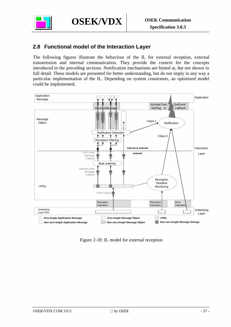
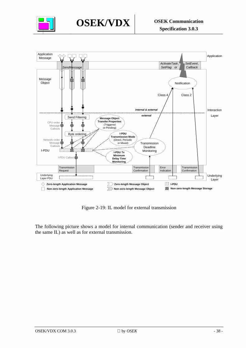
2.8 Functional model of the Interaction Layer
The following figures illustrate the behaviour of the IL for external reception, external transmission and internal communication. They provide the context for the concepts introduced in the preceding sections. Notification mechanisms are hinted at, but not shown in full detail. These models are presented for better understanding, but do not imply in any way a particular implementation of the IL. Depending on system constraints, an optimised model could be implemented.
Notification Detection
ActivateTask , SetEvent , SetFlag or CallbackReceiveMessage
Reception Filtering
I-PDU
Message Object
Underlying Layer PDU
Underlying Layer
Application
Zero-length Application Message
Non-zero-length Application Message
Class 1
Interaction
Layer
internal & external
external
Notification
Application Message
ReceptionIndication
Error Indication
Reception Indication
I-PDU Callout
Byte ordering
Network-order Message Callouts
CPU-order Message Callouts
Reception Deadline
Monitoring
Class 3
Zero-length Message Object I-PDUNon-zero-length Message StorageNon-zero-length Message Object
Figure 2-18: IL model for external reception
OSEK/VDX OSEK Communication Specification 3.0.3
OSEK/VDX COM 3.0.3 by OSEK - 38 -
TransmissionRequest
Transmission Confirmation
Error Indication
Transmission Confirmation
ActivateTask , SetEvent , SetFlag or CallbackSendMessage
I-PDU Callout
I-PDU
Message Object
Underlying Layer PDU
Underlying Layer
Application
Transmission Deadline
Monitoring
Zero-length Application Message
Non-zero-length Application Message
Class 2Class 4
Interaction
Layer
internal & external
external
I-PDUTransmission Mode
(Direct, Periodicor Mixed)
Notification
Application Message
I-PDU TxMinimum
Delay Time Monitoring
Byte ordering
Network-order Message Callouts
CPU-order Message Callouts
Send Filtering Message ObjectTransfer Properties
(Triggeredor Pending)
Zero-length Message Object I-PDUNon-zero-length Message StorageNon-zero-length Message Object
Figure 2-19: IL model for external transmission
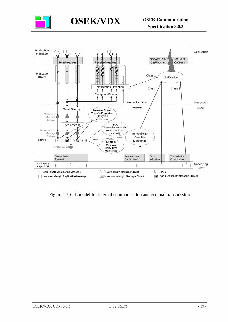
The following picture shows a model for internal communication (sender and receiver using the same IL) as well as for external transmission.
OSEK/VDX OSEK Communication Specification 3.0.3
OSEK/VDX COM 3.0.3 by OSEK - 39 -
TransmissionRequest
Transmission Confirmation
Error Indication
Transmission Confirmation
ActivateTask , SetEvent , SetFlag or CallbackSendMessage ReceiveMessage
Reception Filtering
I-PDU Callout
I-PDU
Message Object
Underlying Layer
Application
Byte ordering
Network -order Message Callouts
CPU-order Message Callouts
Transmission Deadline
Monitoring
Zero-length Application Message
Non-zero-length Application Message
Class 2Class 4
Class 1
Interaction
Layer
internal & external
external
I-PDUTransmission Mode
(Direct, Periodicor Mixed)
Send Filtering
Notification Detection
Notification
Application Message
Message ObjectTransfer Properties
(Triggeredor Pending)
I-PDU TxMinimum
Delay Time Monitoring
Zero-length Message Object I-PDUNon-zero-length Message StorageNon-zero-length Message Object
Underlying Layer PDU
Figure 2-20: IL model for internal communication and external transmission

OSEK/VDX OSEK Communication Specification 3.0.3
OSEK/VDX COM 3.0.3 by OSEK - 40 -
2.9 Interfaces
The system service interface is ISO/ANSI-C. Its implementation is normally a function call, but may also be solved differently, by using C pre-processor macros, for example. A specific type of implementation cannot be assumed.
OSEK COM services may internally call OSEK OS services. When OSEK COM uses OSEK OS services internally, any additional restrictions imposed upon the application by OSEK OS are also imposed upon OSEK COM. The return value of the OSEK API services has precedence over the output parameters.
If an OSEK API service returns an error, the values of the output parameters are undefined. The sequence of error checking within OSEK COM is not specified. Whenever multiple errors occur, it is implementation-dependent which status is returned to the application.
OSEK/VDX OSEK Communication Specification 3.0.3
OSEK/VDX COM 3.0.3 by OSEK - 41 -
2.9.1 Interface to OSEK Indirect NM The following services are provided by OSEK Indirect NM as callback functions for OSEK COM to inform OSEK Indirect NM of deadline monitoring results. They provide a fifth notification mechanism, NMCallback. This notification mechanism is identical to the COMCallback mechanism described in section 2.6.2 except that the interface complies to the definition of I_MessageTransfer.ind and I_MessageTimeOut.ind, that is:
• NMCallback routines have no return value, and
• NMCallback routines pass a 16-bit unsigned integer value as parameter. Both the name of the NMCallback routine and the value of the parameter passed to it are statically defined in OIL. To allow for proper configuration, implementations of Indirect NM shall describe implementation-specific naming conventions (what are the C language names for I_MessageTransfer.ind and I_MessageTimeOut.ind) and parameter conventions (how do parameter values map to monitored I-PDUs).
2.9.1.1 I-PDU transfer indication
Service name: I_MessageTransfer
Service primitive: I_MessageTransfer.ind (<MonitoredIPDU>)
Parameter (in):
MonitoredIPDU 16-bit unsigned integer value identifying the I-PDU to be monitored.
Parameter (out): None.
Description: OSEK COM informs OSEK Indirect NM via the service primitive I_MessageTransfer.ind that a monitored I-PDU has been received from a remote node or that a monitored I-PDU has been transmitted by the local node.
2.9.1.2 I-PDU time-out indication
Service name: I_MessageTimeOut
Service primitive: I_MessageTimeOut.ind (<MonitoredIPDU>)
Parameter (in):
MonitoredIPDU 16-bit unsigned integer value identifying the I-PDU to be monitored.
Parameter (out): None.
Description: OSEK COM informs OSEK Indirect NM via the service primitive I_MessageTimeOut.ind that a time-out has occurred for a monitored I-PDU received from a remote node or for a monitored I-PDU transmitted by the local node.
OSEK/VDX OSEK Communication Specification 3.0.3
OSEK/VDX COM 3.0.3 by OSEK - 42 -
2.9.2 Application Program Interface (API)
2.9.2.1 Service parameter types This section describes the types of API service in/out parameters.
2.9.2.1.1 StatusType Description:
OSEK COM defines communication-specific status codes. The following naming conventions shall apply:
The names of all status codes which are applicable throughout the whole of OSEK (universal status codes) shall start with E_. There is only one universal status code: E_OK.
The names of all status codes which are defined by OSEK COM (communication-specific status codes) shall start with E_COM_, e.g. E_COM_NOMSG.
The following table lists the universal status codes used by OSEK COM and the communication-specific status codes defined by OSEK COM:
Status code Description E_OK Service call has succeeded. E_COM_ID Given message or mode identifier is out of range or invalid. E_COM_LENGTH Given data length is out of range. E_COM_LIMIT Overflow of message queue. E_COM_NOMSG Message queue is empty.
Table 2-2: Status codes used and/or defined by OSEK COM
The system designer can add implementation-specific status codes for OSEK COM. The names of all implementation-specific status codes shall start with E_COM_SYS_, e.g. E_COM_SYS_DISCONNECTED.
An implementation-specific status code may either yield an error which is encountered by the OSEK COM service when calling an OSEK system service like, for example, ActivateTask, or a specific error of the OSEK COM service itself. In the former case, it is recommended that the implementation-specific status code returned is that of the respective OSEK system service. Otherwise, the implementation-specific status code shall be a status code in the system-reserved number space of OSEK COM (see OSEK Binding Specification).
All implementation-specific status codes shall be described in the vendor-specific documentation of an implementation.
Refer to the OSEK Binding Specification for more information on the StatusType parameter.
OSEK/VDX OSEK Communication Specification 3.0.3
OSEK/VDX COM 3.0.3 by OSEK - 43 -
2.9.2.1.2 MessageIdentifier
Type: Scalar
Range: Application-specific, depends on the range of message identifiers.
Description: OSEK COM message object identifier.
2.9.2.1.3 ApplicationDataRef
Type: Reference to a data field in the application
Range: Implementation-specific.
Description: Pointer to the data field of an application message.
2.9.2.1.4 COMLengthType
Type: Scalar
Range: Depends on the communication protocol used.
Description: Data length.
2.9.2.1.5 LengthRef
Type: Reference to COMLengthType, see section 2.9.2.1.4.
Range: Depends on the communication protocol used.
Description: Pointer to a data field containing length information.
2.9.2.1.6 FlagValue
Type: Enumeration
Range: COM_FALSE, COM_TRUE
OSEK/VDX OSEK Communication Specification 3.0.3
OSEK/VDX COM 3.0.3 by OSEK - 44 -
Description: Current state of a message flag.
2.9.2.1.7 COMApplicationModeType
Type: Scalar
Range: Application-specific, depends on the number of COM application modes.
Description: Identifier for selected COM application mode.
2.9.2.1.8 COMShutdownModeType
Type: Scalar
Range: COM_SHUTDOWN_IMMEDIATE
Description: Identifier for selected COM shutdown mode.
2.9.2.1.9 CalloutReturnType
Type: Enumeration
Range: COM_FALSE, COM_TRUE
Description: Indicates at the exit of a callout whether the IL shall continue or abandon further processing of the current message or I-PDU.
2.9.2.1.10 COMServiceIdType
Type: Enumeration
Range: COMServiceId_xx with xx being the name of an OSEK COM service.
Description: Unique identifier of an OSEK COM service. Example: COMServiceId_SendMessage.
OSEK/VDX OSEK Communication Specification 3.0.3
OSEK/VDX COM 3.0.3 by OSEK - 45 -
2.9.2.2 Start-up services
2.9.2.2.1 StartCOM
Service name: StartCOM Syntax: StatusType StartCOM (COMApplicationModeType <Mode>)
Parameter (in):
Mode COM application mode.
Parameter (out): None.
Description: The service StartCOM starts and initialises the OSEK COM implementation in the requested application mode.
If StartCOM fails, initialisation of the OSEK COM implementation aborts and StartCOM returns a status code as specified below.
StartCOM shall be called from within a task if an OSEK-compliant operating system is used. Before returning, the service StartCOM calls the application function StartCOMExtension.
Caveats: The hardware and low-level resources used by OSEK COM shall be initialised before StartCOM is called otherwise undefined behaviour results.
StartCOM does not enable periodic transmission of messages. If needed, StartPeriodic can be called from StartCOMExtension. StartCOM does not stop periodic transmission when StartCOMExtension returns.
StartCOM returns the status code returned by StartCOMExtension if this is different from E_OK.
Status:
Standard: • This service returns E_OK if the initialisation completed
successfully. • This service returns an implementation-specific status code if the
initialisation was not completed successfully.
Extended:
In addition to the standard status codes defined above, the following status code is supported: • This service returns E_COM_ID if the parameter <Mode> is out
of range.
OSEK/VDX OSEK Communication Specification 3.0.3
OSEK/VDX COM 3.0.3 by OSEK - 46 -
2.9.2.2.2 StopCOM
Service name: StopCOM
Syntax: StatusType StopCOM (COMShutdownModeType <Mode>)
Parameter (in):
Mode COM_SHUTDOWN_IMMEDIATE
The shutdown occurs immediately without waiting for pending operations to complete.
Parameter (out): None.
Description: The service StopCOM causes all OSEK COM activity to cease immediately. All resources used by OSEK COM are returned or left in an inactive state. Data loss is possible.
StopCOM stops all periodic transmission of messages.
When StopCOM completes successfully the system is left in a state in which StartCOM can be called to re-initialise OSEK COM.
Status:
Standard: • This service returns E_OK if OSEK COM was shut down
successfully. • This service returns an implementation-specific status code if the
shutdown was not completed successfully.
Extended:
In addition to the standard status codes defined above, the following status code is supported: • This service returns E_COM_ID if the parameter <Mode> is out
of range.
2.9.2.2.3 GetCOMApplicationMode
Service name: GetCOMApplicationMode Syntax: COMApplicationModeType GetCOMApplicationMode (void)
Parameter (in): None.
Parameter (out): None. Description: The service GetCOMApplicationMode returns the current COM
application mode. It may be used to write mode-dependent application code.
Particularities: If GetCOMApplicationMode is called before StartCOM is called, undefined behaviour results.
Return value: Current COM application mode.
OSEK/VDX OSEK Communication Specification 3.0.3
OSEK/VDX COM 3.0.3 by OSEK - 47 -
2.9.2.2.4 InitMessage
Service name: InitMessage Syntax: StatusType InitMessage (
MessageIdentifier <Message>,
ApplicationDataRef <DataRef>
)
Parameter (in):
Message Message identifier (C identifier).
DataRef Reference to the application’s message initialisation data.
Parameter (out): none Description: The service InitMessage initialises the message object identified by
<Message> with the application data referenced by the <DataRef> parameter.
Particularities: This function may be called in StartCOMExtension in order to change the default initialisation.
For dynamic-length messages, the length of the message is initialised to its maximum. If InitMessage initialises a transmission message object directly in the I-PDU, additionally byte order conversion is performed and both the CPU-order and the Network-order Message Callouts are called.
Status:
Standard: • This service returns E_OK if the initialisation of the message
object completed successfully. • This service returns an implementation-specific status code if the
initialisation did not complete successfully.
Extended:
In addition to the standard status code defined above, the following status code is supported: • This service returns E_COM_ID if the parameter <Message> is
out of range or refers to a zero-length message or to an internal transmit message.
2.9.2.2.5 StartPeriodic
Service name: StartPeriodic Syntax: StatusType StartPeriodic (void)
Parameter (in): None.
Parameter (out): None.
OSEK/VDX OSEK Communication Specification 3.0.3
OSEK/VDX COM 3.0.3 by OSEK - 48 -
Description: The service StartPeriodic starts periodic transmission of all messages using either the Periodic or the Mixed Transmission Modes, unless periodic transmission is already started for these messages.
Particularities: Each call to StartPeriodic re-initialises and re-starts periodic transmission completely, i.e. taking into account defined time offsets.
Status:
Standard and Extended: • This service returns E_OK if periodic transmission was started
successfully. • This service returns an implementation-specific status code if
starting of periodic transmission was not completed successfully.
2.9.2.2.6 StopPeriodic
Service name: StopPeriodic Syntax: StatusType StopPeriodic (void)
Parameter (in): None.
Parameter (out): None.
Description: The service StopPeriodic stops periodic transmission of all messages using either the Periodic or the Mixed Transmission Modes, unless periodic transmission is already stopped for these messages.
When StopPeriodic has completed successfully the system is left in a state in which StartPeriodic can be called to restart periodic transmission of all messages using either the Periodic or the Mixed Transmission Modes.
Status:
Standard and Extended: • This service returns E_OK if periodic transmission was stopped
successfully. • This service returns an implementation-specific status code if
stopping periodic transmission was not completed successfully.
OSEK/VDX OSEK Communication Specification 3.0.3
OSEK/VDX COM 3.0.3 by OSEK - 49 -
2.9.2.3 Notification mechanism support services
2.9.2.3.1 ReadFlag
Service name: ReadFlag Syntax: FlagValue ReadFlag_<Flag>()
Parameter (in): None.
Parameter (out): None.
Description: This service returns COM_TRUE if <Flag> is set, otherwise it returns COM_FALSE.
Particularities: The flag is identified by the name <Flag>; this name is part of the service name as shown in the syntax description3. The OSEK COM implementation has to provide one ReadFlag service for each flag.
Return value:
FlagValue Value of the flag.
2.9.2.3.2 ResetFlag
Service name: ResetFlag Syntax: void ResetFlag_<Flag>()
Parameter (in): None.
Parameter (out): None.
Description: This service resets <Flag>.
Particularities: The flag is identified by the name <Flag>; this name is part of the service name as shown in the syntax description4. The OSEK COM implementation has to provide one ResetFlag service for each flag.
Status: None.
______________________________ 3 For a given flag ABC, the name of the macro to read the flag is ReadFlag_ABC(). 4 For a given flag ABC, the name of the macro to reset the flag is ResetFlag_ABC().
OSEK/VDX OSEK Communication Specification 3.0.3
OSEK/VDX COM 3.0.3 by OSEK - 50 -
2.9.2.4 Communication services
2.9.2.4.1 SendMessage
Service name: SendMessage
Syntax: StatusType SendMessage (
MessageIdentifier <Message>,
ApplicationDataRef <DataRef>
)
Parameter (in):
Message Message identifier (C identifier).
DataRef Reference to the application's message data to be transmitted.
Parameter (out): None.
Description: The service SendMessage updates the message object identified by <Message> with the application message referenced by the <DataRef> parameter.
External communication:
If <Message> has the Triggered Transfer Property, the update is followed by immediate transmission of the I-PDU associated with the message except when the message is packed into an I-PDU with Periodic Transmission Mode; in this case, no transmission is initiated by the call to this service.
If <Message> has the Pending Transfer Property, no transmission is caused by the update.
The service SendMessage resets all flags (Notification classes 2 and 4) associated with <Message>.
Internal communication:
The message <Message> is routed to the receiving part of the IL.
Status:
Standard: • This service returns E_OK if the service operation completed
successfully.
Extended:
In addition to the standard status code defined above, the following status code is supported: • This service returns E_COM_ID if the parameter <Message> is
out of range or if it refers to a message that is received or to a dynamic-length or zero-length message.
OSEK/VDX OSEK Communication Specification 3.0.3
OSEK/VDX COM 3.0.3 by OSEK - 51 -
2.9.2.4.2 ReceiveMessage
Service name: ReceiveMessage
Syntax: StatusType ReceiveMessage (
MessageIdentifier <Message>,
ApplicationDataRef <DataRef>
)
Parameter (in):
Message Message identifier (C identifier).
Parameter (out):
DataRef Reference to the application's message area in which to store the received data.
Description: The service ReceiveMessage updates the application message referenced by <DataRef> with the data in the message object identified by <Message>. It resets all flags (Notification classes 1 and 3) associated with <Message>.
Status:
Standard: • This service returns E_OK if data in the queued or unqueued
message identified by <Message> are available and returned to the application successfully.
• This service returns E_COM_NOMSG if the queued message identified by <Message> is empty.
• This service returns E_COM_LIMIT if an overflow of the message queue identified by <Message> occurred since the last call to ReceiveMessage for <Message>. E_COM_LIMIT indicates that at least one message has been discarded since the message queue filled. Nevertheless the service is performed and a message is returned. The service ReceiveMessage clears the overflow condition for <Message>.
Extended:
In addition to the standard status codes defined above, the following status code is supported: • This service returns E_COM_ID if the parameter <Message> is
out of range or if it refers to message that is sent or to a dynamic-length or zero-length message.
OSEK/VDX OSEK Communication Specification 3.0.3
OSEK/VDX COM 3.0.3 by OSEK - 52 -
2.9.2.4.3 SendDynamicMessage
Service name: SendDynamicMessage
Syntax: StatusType SendDynamicMessage (
MessageIdentifier <Message>,
ApplicationDataRef <DataRef>,
LengthRef <LengthRef>
)
Parameter (in):
Message Message identifier (C identifier).
DataRef Reference to the application's message data to be transmitted.
LengthRef Reference to a value containing the length of the data in the message.
Parameter (out): None. Description: The service SendDynamicMessage updates the message object
identified by <Message> with the application data referenced by the <DataRef> parameter.
If <Message> has the Triggered Transfer Property, the update is followed by immediate transmission of the I-PDU associated with the message except when the message is packed into an I-PDU with Periodic Transmission Mode; in this case, no transmission takes place.
If <Message> has the Pending Transfer Property, no transmission is caused by the update. The service SendDynamicMessage resets all flags (Notification classes 2 and 4) associated with <Message>.
Particularities: This service can be used with unqueued messages only. This service is provided for external communication only.
Status:
Standard: • This service returns E_OK if the service operation completed
successfully.
Extended:
In addition to the standard status code defined above, the following status codes are supported: • This service returns E_COM_ID if the parameter <Message> is
out of range or if it refers to a received message, a static-length message or a zero-length message.
• This service returns E_COM_LENGTH if the value to which <LengthRef> points is not within the range 0 to the maximum length defined for <Message>.
OSEK/VDX OSEK Communication Specification 3.0.3
OSEK/VDX COM 3.0.3 by OSEK - 53 -
2.9.2.4.4 ReceiveDynamicMessage
Service name: ReceiveDynamicMessage
Syntax: StatusType ReceiveDynamicMessage (
MessageIdentifier <Message>,
ApplicationDataRef <DataRef>,
LengthRef <LengthRef>
)
Parameter (in):
Message Message identifier (C identifier).
Parameter (out):
DataRef Reference to the application's message area in which to store the received data.
LengthRef Reference to an application variable in which to store the message length.
Description: The service ReceiveDynamicMessage updates the application message referenced by <DataRef> with the data in the message object identified by <Message>. It resets all flags (Notification classes 1 and 3) associated with <Message>.
The length of the received message data is placed in the variable referenced by <LengthRef>.
Particularities: This service can be used with unqueued messages only. This service is provided for external communication only.
Status:
Standard: • This service returns E_OK if data in the unqueued message
identified by <Message> is returned to the application successfully.
Extended:
In addition to the standard status code defined above, the following status code is supported: • This service returns E_COM_ID if the parameter <Message> is
out of range or if it refers to a message that is sent, a queued message, a static-length message or a zero-length message.
OSEK/VDX OSEK Communication Specification 3.0.3
OSEK/VDX COM 3.0.3 by OSEK - 54 -
2.9.2.4.5 SendZeroMessage
Service name: SendZeroMessage
Syntax: StatusType SendZeroMessage (
MessageIdentifier <Message>
)
Parameter (in):
Message Message identifier of the zero-length message (C identifier).
Parameter (out): None.
Description: External communication:
The service SendZeroMessage causes immediate transmission of the I-PDU associated with the zero-length message <Message> except when this message is associated with an I-PDU with Periodic Transmission Mode; in this case, no transmission is initiated by the call to this service.
The service SendZeroMessage resets all flags (Notification classes 2 and 4) associated with <Message>.
Internal communication:
The message <Message> is routed to the receiving part of the IL for notification.
Status:
Standard: • This service returns E_OK if the service operation completed
successfully.
Extended:
In addition to the standard status code defined above, the following status code is supported: • This service returns E_COM_ID if the parameter <Message> is
out of range or if it refers to a non-zero-length message.
2.9.2.4.6 GetMessageStatus
Service name: GetMessageStatus Syntax: StatusType GetMessageStatus (
MessageIdentifier <Message>
)
Parameter (in):
Message Message identifier (C identifier).
Parameter (out): None.
OSEK/VDX OSEK Communication Specification 3.0.3
OSEK/VDX COM 3.0.3 by OSEK - 55 -
Description: The service GetMessageStatus returns the current status of the message object <Message>.
Status:
Standard: • This service returns E_COM_NOMSG if the message queue
identified by <Message> is empty. • This service returns E_COM_LIMIT if an overflow of the message
queue identified by <Message> occurred since the last call to ReceiveMessage for <Message>.
• This service returns E_OK if none of the conditions specified above is applicable or fulfilled and no error indication is present.
Extended:
In addition to the standard status codes defined above, the following status code is supported: • This service returns E_COM_ID if the parameter <Message> is
out of range or if it does not refer to a queued message.
2.9.2.4.7 COMErrorGetServiceId
Service name: COMErrorGetServiceId Syntax: COMServiceIdType COMErrorGetServiceId (void)
Parameter (in): None.
Parameter (out): None. Description: The service COMErrorGetServiceId (which may be implemented as a
macro) returns the identifier of the OSEK COM service where the error occurred.
Caveats: The service COMErrorGetServiceId shall only be called from COMErrorHook, otherwise the return value is undefined.
Return value: Service Identifier.
2.9.2.4.8 COMError_Name1_Name2 macros
COMError_Name1_Name2 is the pattern for the names of macros which are used to access (from within the function COMErrorHook) parameters of the OSEK COM service which called COMErrorHook.
The parts of the macro names are defined as follows:
• COMError: is a fixed prefix.
• Name1: is the name of the service, e.g. SendMessage.
• Name2: is the name of the parameter, e.g. DataRef.
OSEK/VDX OSEK Communication Specification 3.0.3
OSEK/VDX COM 3.0.3 by OSEK - 56 -
2.9.3 Routines provided by the application
2.9.3.1 StartCOMExtension
Service name: StartCOMExtension Syntax: StatusType StartCOMExtension (void)
Parameter (in): None.
Parameter (out): None. Description: The routine StartCOMExtension is provided by the application and is
called by the OSEK COM implementation at the end of the StartCOM routine. It can be used to extend the start-up routine with initialisation functions (e.g. InitMessage) or additional start-up functions (e.g. StartPeriodic).
Status:
Standard and Extended: • This service returns E_OK if it completed successfully. • This service returns an implementation-specific status code to
indicate that an error occurred during its execution.
2.9.3.2 Callouts
Service name: COMCallout(CalloutRoutineName) Syntax: COMCallout (CalloutRoutineName)
Parameter (in): None.
Parameter (out): None.
Description: The routine CalloutRoutineName is provided by the application and is called by the OSEK COM implementation. It can be used to extend the OSEK COM functionality with application-related functions (e.g. gatewaying).
The return value indicates whether the IL shall continue (COM_TRUE) or abandon (COM_FALSE) further processing of this message or I-PDU after the callout returns.
Return value: The routine CalloutRoutineName shall return a return value of the type CalloutReturnType. The return value contains information regarding whether or not to continue processing.
OSEK/VDX OSEK Communication Specification 3.0.3
OSEK/VDX COM 3.0.3 by OSEK - 57 -
2.9.3.3 COMErrorHook
Service name: COMErrorHook Syntax: void COMErrorHook (
StatusType <Error>
)
Parameter (in):
Error Identifier of the occurred error.
Parameter (out): None.
Description: The service COMErrorHook is provided by the application and is called by OSEK COM at the end of an OSEK COM service which returns a status code not equal to E_OK.
Status: None.
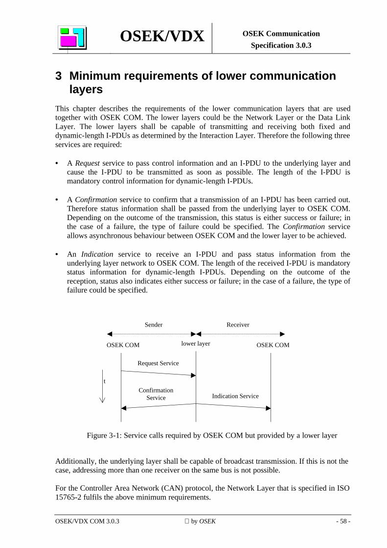
OSEK/VDX OSEK Communication Specification 3.0.3
OSEK/VDX COM 3.0.3 by OSEK - 58 -
3 Minimum requirements of lower communication layers
This chapter describes the requirements of the lower communication layers that are used together with OSEK COM. The lower layers could be the Network Layer or the Data Link Layer. The lower layers shall be capable of transmitting and receiving both fixed and dynamic-length I-PDUs as determined by the Interaction Layer. Therefore the following three services are required: • A Request service to pass control information and an I-PDU to the underlying layer and
cause the I-PDU to be transmitted as soon as possible. The length of the I-PDU is mandatory control information for dynamic-length I-PDUs.
• A Confirmation service to confirm that a transmission of an I-PDU has been carried out.
Therefore status information shall be passed from the underlying layer to OSEK COM. Depending on the outcome of the transmission, this status is either success or failure; in the case of a failure, the type of failure could be specified. The Confirmation service allows asynchronous behaviour between OSEK COM and the lower layer to be achieved.
• An Indication service to receive an I-PDU and pass status information from the
underlying layer network to OSEK COM. The length of the received I-PDU is mandatory status information for dynamic-length I-PDUs. Depending on the outcome of the reception, status also indicates either success or failure; in the case of a failure, the type of failure could be specified.
lower layerOSEK COM OSEK COM
Sender Receiver
Request Service
Indication ServiceConfirmation
Service
t
Figure 3-1: Service calls required by OSEK COM but provided by a lower layer
Additionally, the underlying layer shall be capable of broadcast transmission. If this is not the case, addressing more than one receiver on the same bus is not possible. For the Controller Area Network (CAN) protocol, the Network Layer that is specified in ISO 15765-2 fulfils the above minimum requirements.
OSEK/VDX OSEK Communication Specification 3.0.3
OSEK/VDX COM 3.0.3 by OSEK - 59 -
4 Conformance Classes Various application software requirements and specific system capabilities (e.g. communication hardware, processor and memory) require different levels of communication software functionality.
OSEK COM defines these levels as "Communication Conformance Classes" (CCCs). The main purpose of the conformance classes is to ensure that applications that have been built for a particular conformance class are portable across different OSEK COM implementations and ECUs featuring that same level of conformance class. Hence different implementations of the same CCC provide the same set of services and functionality to the application. An OSEK COM implementation conforms to a CCC only if it provides all the features defined for that conformance class. However, system generation needs only to link those OSEK COM services that are required for a specific application. A specific CCC is selected at system generation time. OSEK COM defines the following CCCs:
CCCA: CCCA defines the minimum features to support internal communication only; i.e. no support for external communication is available. Unqueued messages shall be supported. No message status information shall be supported in order to allow for a lean implementation of the communication kernel.
The OSEK COM services StartCOM, StopCOM, GetCOMApplicationMode, InitMessage, SendMessage, ReceiveMessage, COMErrorGetServiceId, the COMError_Name1_Name2 macros and Notification Class 1 (except for the Flag notification mechanism) shall be supported.
CCCB: CCCB defines features to support internal communication only; i.e. no support for external communication is available. All features of CCCA shall be supported with the following extensions: message status information (GetMessageStatus API service) and queued messages.
CCC0: CCC0 defines minimum features to support internal and external communication. All features of CCCA shall be supported as well as notification class 2, byte order conversion and Direct Transmission Mode.
CCC1: All features of OSEK COM shall be supported.
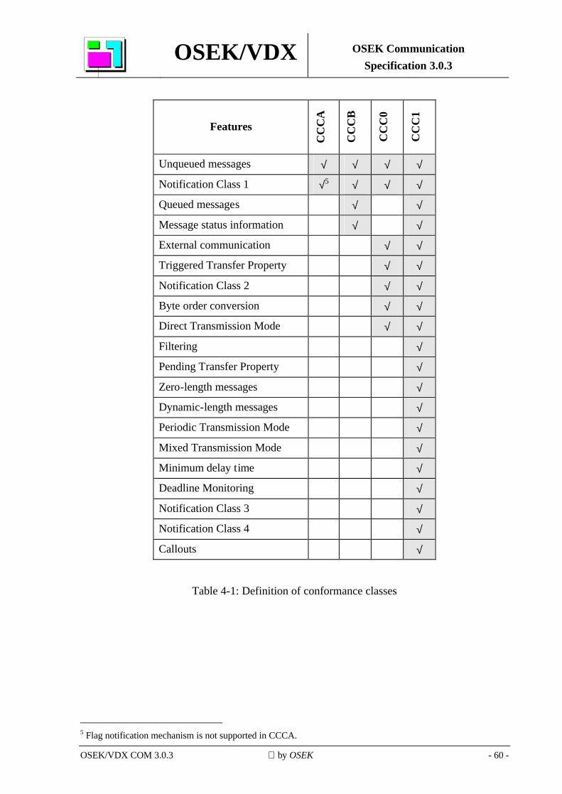
OSEK/VDX OSEK Communication Specification 3.0.3
OSEK/VDX COM 3.0.3 by OSEK - 60 -
Features
CC
CA
CC
CB
CC
C0
CC
C1
Unqueued messages √ √ √ √
Notification Class 1 √5 √ √ √
Queued messages √ √
Message status information √ √
External communication √ √
Triggered Transfer Property √ √
Notification Class 2 √ √
Byte order conversion √ √
Direct Transmission Mode √ √
Filtering √
Pending Transfer Property √
Zero-length messages √
Dynamic-length messages √
Periodic Transmission Mode √
Mixed Transmission Mode √
Minimum delay time √
Deadline Monitoring √
Notification Class 3 √
Notification Class 4 √
Callouts √
Table 4-1: Definition of conformance classes
______________________________ 5 Flag notification mechanism is not supported in CCCA.
OSEK/VDX OSEK Communication Specification 3.0.3
OSEK/VDX COM 3.0.3 by OSEK - 61 -
Appendix A Use of OSEK COM with operating systems other than OSEK OS
It is possible to implement OSEK COM so that it works with operating systems other than the OSEK OS. Such an implementation is simplified by the fact that only a limited amount of OSEK OS entities are used within OSEK COM. To use OSEK COM with another operating system, the following facilities shall be offered by that operating system:
• tasks (basic and extended)
• events
• interrupt service routines (ISR) category 2 Systems which can map these facilities such that they comply with their respective definition in OSEK OS can fully support an OSEK COM implementation.
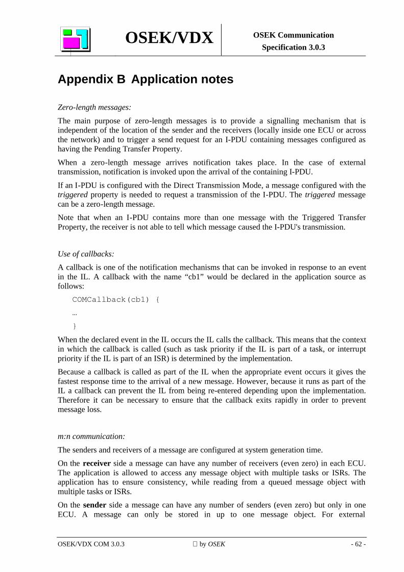
OSEK/VDX OSEK Communication Specification 3.0.3
OSEK/VDX COM 3.0.3 by OSEK - 62 -
Appendix B Application notes
Zero-length messages: The main purpose of zero-length messages is to provide a signalling mechanism that is independent of the location of the sender and the receivers (locally inside one ECU or across the network) and to trigger a send request for an I-PDU containing messages configured as having the Pending Transfer Property.
When a zero-length message arrives notification takes place. In the case of external transmission, notification is invoked upon the arrival of the containing I-PDU.
If an I-PDU is configured with the Direct Transmission Mode, a message configured with the triggered property is needed to request a transmission of the I-PDU. The triggered message can be a zero-length message. Note that when an I-PDU contains more than one message with the Triggered Transfer Property, the receiver is not able to tell which message caused the I-PDU's transmission.
Use of callbacks: A callback is one of the notification mechanisms that can be invoked in response to an event in the IL. A callback with the name “cb1” would be declared in the application source as follows:
COMCallback(cb1) { … }
When the declared event in the IL occurs the IL calls the callback. This means that the context in which the callback is called (such as task priority if the IL is part of a task, or interrupt priority if the IL is part of an ISR) is determined by the implementation. Because a callback is called as part of the IL when the appropriate event occurs it gives the fastest response time to the arrival of a new message. However, because it runs as part of the IL a callback can prevent the IL from being re-entered depending upon the implementation. Therefore it can be necessary to ensure that the callback exits rapidly in order to prevent message loss.
m:n communication: The senders and receivers of a message are configured at system generation time. On the receiver side a message can have any number of receivers (even zero) in each ECU. The application is allowed to access any message object with multiple tasks or ISRs. The application has to ensure consistency, while reading from a queued message object with multiple tasks or ISRs. On the sender side a message can have any number of senders (even zero) but only in one ECU. A message can only be stored in up to one message object. For external
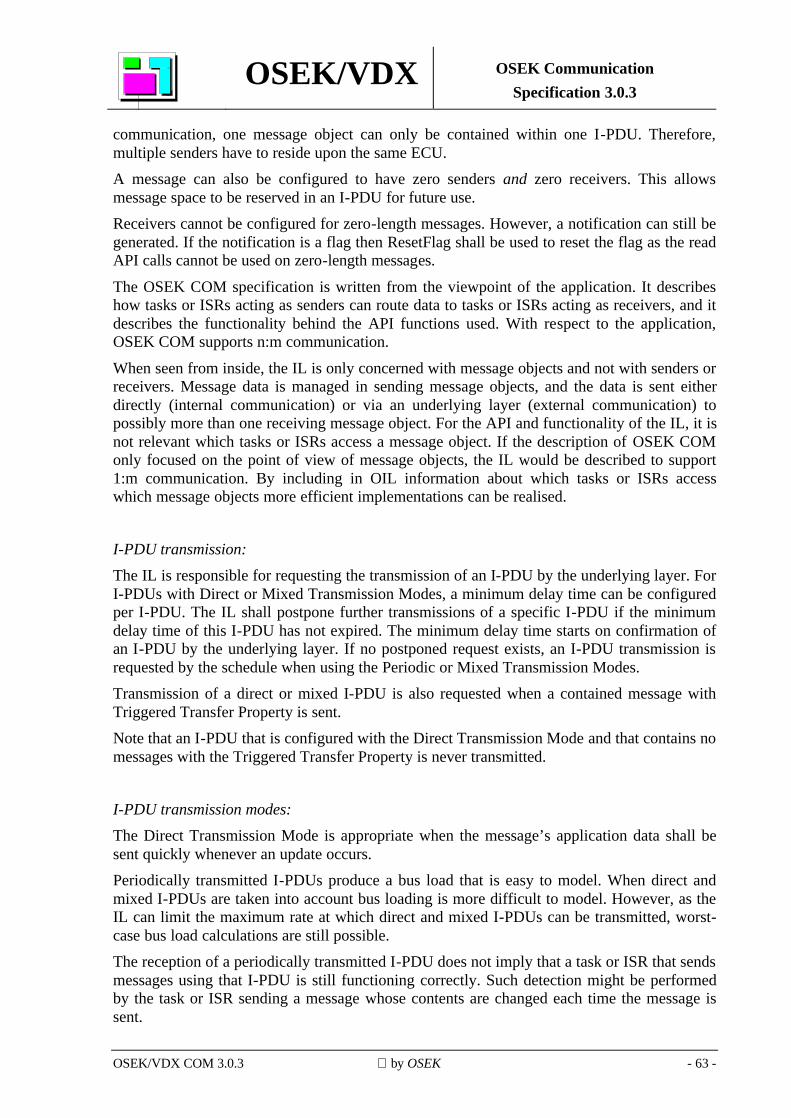
OSEK/VDX OSEK Communication Specification 3.0.3
OSEK/VDX COM 3.0.3 by OSEK - 63 -
communication, one message object can only be contained within one I-PDU. Therefore, multiple senders have to reside upon the same ECU. A message can also be configured to have zero senders and zero receivers. This allows message space to be reserved in an I-PDU for future use. Receivers cannot be configured for zero-length messages. However, a notification can still be generated. If the notification is a flag then ResetFlag shall be used to reset the flag as the read API calls cannot be used on zero-length messages.
The OSEK COM specification is written from the viewpoint of the application. It describes how tasks or ISRs acting as senders can route data to tasks or ISRs acting as receivers, and it describes the functionality behind the API functions used. With respect to the application, OSEK COM supports n:m communication.
When seen from inside, the IL is only concerned with message objects and not with senders or receivers. Message data is managed in sending message objects, and the data is sent either directly (internal communication) or via an underlying layer (external communication) to possibly more than one receiving message object. For the API and functionality of the IL, it is not relevant which tasks or ISRs access a message object. If the description of OSEK COM only focused on the point of view of message objects, the IL would be described to support 1:m communication. By including in OIL information about which tasks or ISRs access which message objects more efficient implementations can be realised.
I-PDU transmission: The IL is responsible for requesting the transmission of an I-PDU by the underlying layer. For I-PDUs with Direct or Mixed Transmission Modes, a minimum delay time can be configured per I-PDU. The IL shall postpone further transmissions of a specific I-PDU if the minimum delay time of this I-PDU has not expired. The minimum delay time starts on confirmation of an I-PDU by the underlying layer. If no postponed request exists, an I-PDU transmission is requested by the schedule when using the Periodic or Mixed Transmission Modes. Transmission of a direct or mixed I-PDU is also requested when a contained message with Triggered Transfer Property is sent. Note that an I-PDU that is configured with the Direct Transmission Mode and that contains no messages with the Triggered Transfer Property is never transmitted.
I-PDU transmission modes: The Direct Transmission Mode is appropriate when the message’s application data shall be sent quickly whenever an update occurs. Periodically transmitted I-PDUs produce a bus load that is easy to model. When direct and mixed I-PDUs are taken into account bus loading is more difficult to model. However, as the IL can limit the maximum rate at which direct and mixed I-PDUs can be transmitted, worst-case bus load calculations are still possible. The reception of a periodically transmitted I-PDU does not imply that a task or ISR that sends messages using that I-PDU is still functioning correctly. Such detection might be performed by the task or ISR sending a message whose contents are changed each time the message is sent.
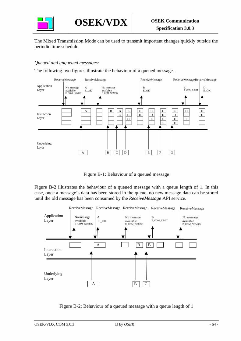
OSEK/VDX OSEK Communication Specification 3.0.3
OSEK/VDX COM 3.0.3 by OSEK - 64 -
The Mixed Transmission Mode can be used to transmit important changes quickly outside the periodic time schedule.
Queued and unqueued messages: The following two figures illustrate the behaviour of a queued message.
ApplicationLayer
InteractionLayer
UnderlyingLayer
A B B B C C C C D EC C D D D D E F
D E E E FF F
ReceiveMessageg
ReceiveMessage ReceiveMessage ReceiveMessageReceiveMessage
No messageavailableE_COM_NOMSG
AE_OK
No messageavailableE_COM_NOMSG
BE_OK
CE_COM_LIMIT
DE_OK
A B C D E F G
Figure B-1: Behaviour of a queued message
Figure B-2 illustrates the behaviour of a queued message with a queue length of 1. In this case, once a message’s data has been stored in the queue, no new message data can be stored until the old message has been consumed by the ReceiveMessage API service.
ApplicationLayer
InteractionLayer
UnderlyingLayer
A
ReceiveMessage ReceiveMessage ReceiveMessage ReceiveMessage ReceiveMessage
No messageavailableE_COM_NOMSG
AE_OK
No messageavailableE_COM_NOMSG
BE_COM_LIMIT
No messageavailableE_COM_NOMSG
B C
B B
A
Figure B-2: Behaviour of a queued message with a queue length of 1
OSEK/VDX OSEK Communication Specification 3.0.3
OSEK/VDX COM 3.0.3 by OSEK - 65 -
Figure B-3 shows the behaviour of an unqueued message illustrating how the message data is overwritten each time a new message is received. Note that the behaviour of an unqueued message is not the same as that of a queued message with a queue length of 1.
ApplicationLayer
InteractionLayer
UnderlyingLayer
A
ReceiveMessage ReceiveMessage ReceiveMessage ReceiveMessageMessage valueset atinitialisation
E_OK
AE_OK
AE_OK
CE_OK
A B C C
A CB
Figure B-3: Behaviour of an unqueued message
Message data change detection: This section is concerned with detecting changes in data between one instance of a message and another.
If an I-PDU containing a message is transmitted more often than the message is sent by the application, the situation can arise where a datum sent once by an application is received more than once by another. In some circumstances this can be a problem in the receiver if it assumes that notification implies a new message, or can cause unnecessary CPU load due to the receiver being notified more often than necessary. A number of techniques can be employed with OSEK COM to avoid incorrect multiple data reception. The filter algorithms that permit the passage of messages with contents different from the previous message are the solution that is easiest to implement. These algorithms are F_NewIsDifferent and F_MaskedNewDiffersMaskedOld, although in specific cases others can achieve a similar purpose. The filter algorithms are probably useful in a large majority of cases. However, there are some circumstances where they are not applicable. For example, where the datum is part of a structure that constitutes the message, or where it is necessary to have sequences of the same value. Where a message is a structure it is possible to add another element to the structure that is a sequence number. This sequence number does not need to have a large range; two values are adequate in many cases. When the structure is updated the sequence number is incremented,
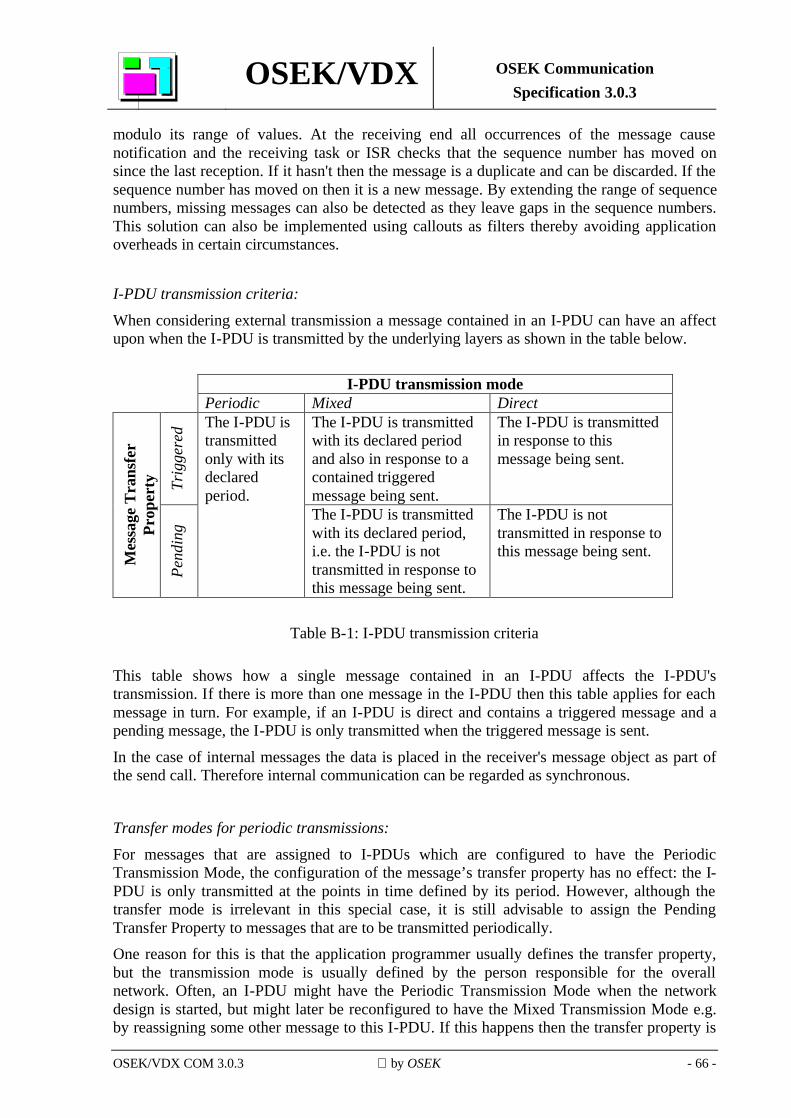
OSEK/VDX OSEK Communication Specification 3.0.3
OSEK/VDX COM 3.0.3 by OSEK - 66 -
modulo its range of values. At the receiving end all occurrences of the message cause notification and the receiving task or ISR checks that the sequence number has moved on since the last reception. If it hasn't then the message is a duplicate and can be discarded. If the sequence number has moved on then it is a new message. By extending the range of sequence numbers, missing messages can also be detected as they leave gaps in the sequence numbers. This solution can also be implemented using callouts as filters thereby avoiding application overheads in certain circumstances.
I-PDU transmission criteria: When considering external transmission a message contained in an I-PDU can have an affect upon when the I-PDU is transmitted by the underlying layers as shown in the table below.
I-PDU transmission mode
Periodic Mixed Direct
Trig
gere
d The I-PDU is transmitted with its declared period and also in response to a contained triggered message being sent.
The I-PDU is transmitted in response to this message being sent.
Mes
sage
Tra
nsfe
r Pr
oper
ty
Pend
ing
The I-PDU is transmitted only with its declared period.
The I-PDU is transmitted with its declared period, i.e. the I-PDU is not transmitted in response to this message being sent.
The I-PDU is not transmitted in response to this message being sent.
Table B-1: I-PDU transmission criteria
This table shows how a single message contained in an I-PDU affects the I-PDU's transmission. If there is more than one message in the I-PDU then this table applies for each message in turn. For example, if an I-PDU is direct and contains a triggered message and a pending message, the I-PDU is only transmitted when the triggered message is sent.
In the case of internal messages the data is placed in the receiver's message object as part of the send call. Therefore internal communication can be regarded as synchronous.
Transfer modes for periodic transmissions: For messages that are assigned to I-PDUs which are configured to have the Periodic Transmission Mode, the configuration of the message’s transfer property has no effect: the I-PDU is only transmitted at the points in time defined by its period. However, although the transfer mode is irrelevant in this special case, it is still advisable to assign the Pending Transfer Property to messages that are to be transmitted periodically. One reason for this is that the application programmer usually defines the transfer property, but the transmission mode is usually defined by the person responsible for the overall network. Often, an I-PDU might have the Periodic Transmission Mode when the network design is started, but might later be reconfigured to have the Mixed Transmission Mode e.g. by reassigning some other message to this I-PDU. If this happens then the transfer property is
OSEK/VDX OSEK Communication Specification 3.0.3
OSEK/VDX COM 3.0.3 by OSEK - 67 -
again relevant and it should have been set to the correct value initially so as not to have to worry about correct transfer property at this later point in time.
Variable I-PDU Transmission Periods: Periodic I-PDUs have their periods fixed at system generation time. However, in certain circumstances, it is necessary to be able to give them different periods: after mode changes, for example. Although OSEK COM does not directly support variable period I-PDUs, they can be implemented using direct I-PDUs containing a triggered message. The messages in the I-PDU that contain data would all be marked as pending and would be filled in by the application as appropriate. Transmission would be achieved by the application sending the triggered message. This might be sent by a task activated from an OSEK OS alarm. By changing the alarm's period at run-time the period of the I-PDU can also be changed. More complex schemes (for example, the task might implement a state machine) can result in arbitrarily complex I-PDU transmission patterns.
Interface to OSEK Indirect NM: The IL needs to call Indirect NM in order to indicate that a message has been transferred or that a message timeout has occurred (see section 2.9.1). This is achieved by defining an NMCallback for a message in a monitored I-PDU. The message can be one that already exists in that I-PDU or a zero-length message used explicitly to cause an NMCallback. Each implementation of Indirect NM might define different names for its I_MessageTransfer.ind and I_MessageTimeOut.ind routines. Therefore the names used are configured as an NMCallback attribute of a message in the OIL file. Additionally, Indirect NM also needs to know which message caused the NMCallback. For this purpose the NMCallback parameter called MonitoredIPDU uniquely identifies the message that caused the NMCallback. As a message can only appear in one I-PDU, and an I-PDU can only appear on one bus, this parameter is sufficient to identify the I-PDU and bus that caused the NMCallback. Therefore, the NMCallback indicates the condition of an I-PDU.
The values passed in the MonitoredIPDU parameter are defined per message in the OIL file. Therefore a unique value can be chosen for each message.
OSEK/VDX OSEK Communication Specification 3.0.3
OSEK/VDX COM 3.0.3 by OSEK - 68 -
Use of Overlapping Messages: COM allows messages in an I-PDU to overlap each other. One message may completely overlap another message or group of messages so that all of them are totally contained within the overlapping message. Alternatively one message may only partially overlap another so that both have I-PDU bits in common and bits that are not in common.
Although overlapping messages have some uses it is expected that they are unusual. Therefore implementations should be designed to make the common case (non-overlapping messages) to be the most efficient. Rules for message initialisation apply equally to overlapping and non-overlapping messages. However, message initialisation does not specify the order in which messages are initialised. Therefore, when initialisation takes place as a result of initial values specified in the OIL file, the resulting message values in overlapping messages can differ between implementations. However, if InitMessage is used message initialisation can be written so that only relevant overlapping fields are set up thereby improving portability. When a system is configured, with or without overlapping messages, all the messages have the appropriate internal data structures generated even though, in a particular COM Application Mode for example, a message is not used. This is because message usage can depend upon information other than the COM Application Mode. No special action is taken in the generation of COM's internal data structures based upon whether or not messages overlap.
The rest of this section describes two possible uses for overlapping messages. Overlapping messages can be useful when a group of signals need to be gatewayed from one network to another. If we assume that the message group occupies space in the I-PDU that has no messages not belonging to the group in it, then a single overlapping message can be used that encompasses all of the messages in the group. This means that the entire message group can be read from one I-PDU and written to another I-PDU simply by reading the single overlapping message. (This is similar to the way that structures work in C.)
A further use of overlapping messages is to allow the format of an I-PDU to be changed in response to, for example, the COM Application Mode, or some tag field within the I-PDU. (This use is similar to unions in C.) In this case any byte order conversion, filtering, copying to message objects and notification still take place for all the messages they are declared for, even if, in a certain mode, a message becomes irrelevant. This is because COM cannot selectively enable or disable messages based upon the COM Application Mode. This implies that, under certain circumstances notifications are generated that are irrelevant. The application code shall be written so that it detects and correctly deals with these situations.
For example, a system has two messages, A and B, that have notifications that activate tasks TA and TB respectively when the message arrives. The messages are packed into the I-PDU so that they overlap. Let us also assume that message A is only relevant in COM Application Mode X and message B is only relevant in COM Application Mode Y.
When the system is initialised, the StartCOMExtension shall read the COM Application Mode in order to decide whether to initialise message A or B.
When the system is running in COM Application Mode X, reception of data in message A causes task TA to be activated. However, as these are in the same I-PDU task TB is also activated.
OSEK/VDX OSEK Communication Specification 3.0.3
OSEK/VDX COM 3.0.3 by OSEK - 69 -
As we are in COM Application Mode X rather than Y, TB's activation is undesirable but unavoidable. Therefore the application shall be written in such a way that this problem is overcome. This can be achieved by the application code that receives the notification checking whether or not the notification is acceptable in the current COM Application Mode and exiting if it is not. An outline of how this might be achieved is shown in the following code example.
TASK(TB) { if(GetCOMApplicationMode() != Y) {
(void)TerminateTask(); } else {
/* we only get here if we are in the correct COM * application mode for this task */ …
} }
Although this makes the task more complex, this only occurs in specific instances of overlapping message use rather than in the core of the IL.

OSEK/VDX OSEK Communication Specification 3.0.3
OSEK/VDX COM 3.0.3 by OSEK - 70 -
Appendix C Callouts This section describes some suggested uses for callouts.
Callouts provide a general mechanism to customise and enhance the behaviour of the IL. Callouts are configured statically, are invoked in response to the passage of a message or I-PDU and cannot be changed at run-time. The prototype for a callout allows it to return a value. This value is treated as a Boolean that can either prevent or allow further processing of the message or I-PDU. Three uses of callouts are now described: custom filtering, gatewaying and replication. Each of these uses can apply equally well to I-PDUs or messages.
Declaration A callout is declared in the application code as follows:
COMCallout(co1) { … }
This declares a callout called “co1”. As callouts have no parameters it is best to have a callout for each separate use. This means that the callout implicitly knows which I-PDU or message it is dealing with.
Custom filtering The CPU-order message callouts can be used to implement custom filtering. When the callout is invoked the message can be checked against some arbitrary criterion and the callout's return value used to indicate whether or not the message passes the filter. Depending upon the callout's return value, the IL either discards the message or continues processing it. For example, a custom filter might be implemented as follows:
COMCallout(filter1) { if(test criterion) {
return COM_TRUE; } else {
return COM_FALSE: }
} so that the message is either discarded or passed based upon the test criterion.
OSEK/VDX OSEK Communication Specification 3.0.3
OSEK/VDX COM 3.0.3 by OSEK - 71 -
Gatewaying In gatewaying, a message or I-PDU is received by the IL and then sent elsewhere - possibly to a different I-PDU on the same bus, or to an I-PDU on a different bus. When the callout is invoked it copies the message or I-PDU to another I-PDU and then optionally initiates transfer of that I-PDU to the underlying layers thereby causing its transmission on the bus. The return code from the callout can be used to indicate whether or not the message or I-PDU shall also be received by the controlling ECU.
Replication An ECU can interface to more than one bus. Therefore it can be necessary to have the same I-PDU transmitted identically on more than one bus. This can be achieved with an I-PDU callout as it can place the contents of the outgoing I-PDU in some other I-PDU (destined for the same or another bus) and initiate its transmission if appropriate.
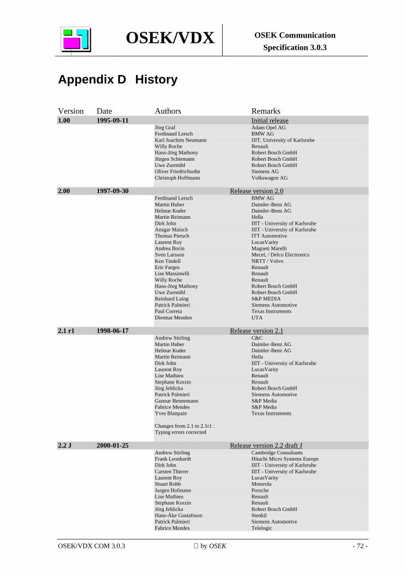
OSEK/VDX OSEK Communication Specification 3.0.3
OSEK/VDX COM 3.0.3 by OSEK - 72 -
Appendix D History Version Date Authors Remarks 1.00 1995-09-11 Initial release
Jörg Graf Adam Opel AG Ferdinand Lersch BMW AG Karl Joachim Neumann IIIT, University of Karlsruhe Willy Roche Renault Hans-Jörg Mathony Robert Bosch GmbH Jürgen Schiemann Robert Bosch GmbH Uwe Zurmühl Robert Bosch GmbH Oliver Friedrichsohn Siemens AG Christoph Hoffmann Volkswagen AG
2.00 1997-09-30 Release version 2.0 Ferdinand Lersch BMW AG Martin Huber Daimler-Benz AG Helmar Kuder Daimler-Benz AG Martin Reimann Hella Dirk John IIIT - University of Karlsruhe Ansgar Maisch IIIT - University of Karlsruhe Thomas Pietsch ITT Automotive Laurent Roy LucasVarity Andrea Borin Magneti Marelli Sven Larsson Mecel, / Delco Electronics Ken Tindell NRTT / Volvo Eric Farges Renault Lise Massimelli Renault Willy Roche Renault Hans-Jörg Mathony Robert Bosch GmbH Uwe Zurmühl Robert Bosch GmbH Reinhard Laing S&P MEDIA Patrick Palmieri Siemens Automotive Paul Correia Texas Instruments Dietmar Menden UTA
2.1 r1 1998-06-17 Release version 2.1 Andrew Stirling C&C Martin Huber Daimler-Benz AG Helmar Kuder Daimler-Benz AG Martin Reimann Hella Dirk John IIIT - University of Karlsruhe Laurent Roy LucasVarity Lise Mathieu Renault Stephane Korzin Renault Jörg Jehlicka Robert Bosch GmbH Patrick Palmieri Siemens Automotive Gunnar Bennemann S&P Media Fabrice Mendes S&P Media Yves Blanpain Texas Instruments Changes from 2.1 to 2.1r1 : Typing errors corrected
2.2 J 2000-01-25 Release version 2.2 draft J Andrew Stirling Cambridge Consultants Frank Leonhardt Hitachi Micro Systems Europe Dirk John IIIT - University of Karlsruhe Carsten Thierer IIIT - University of Karlsruhe Laurent Roy LucasVarity Stuart Robb Motorola Jurgen Hofmann Porsche Lise Mathieu Renault Stephane Korzin Renault Jörg Jehlicka Robert Bosch GmbH Hans-Åke Gustafsson Stenkil Patrick Palmieri Siemens Automotive Fabrice Mendes Telelogic
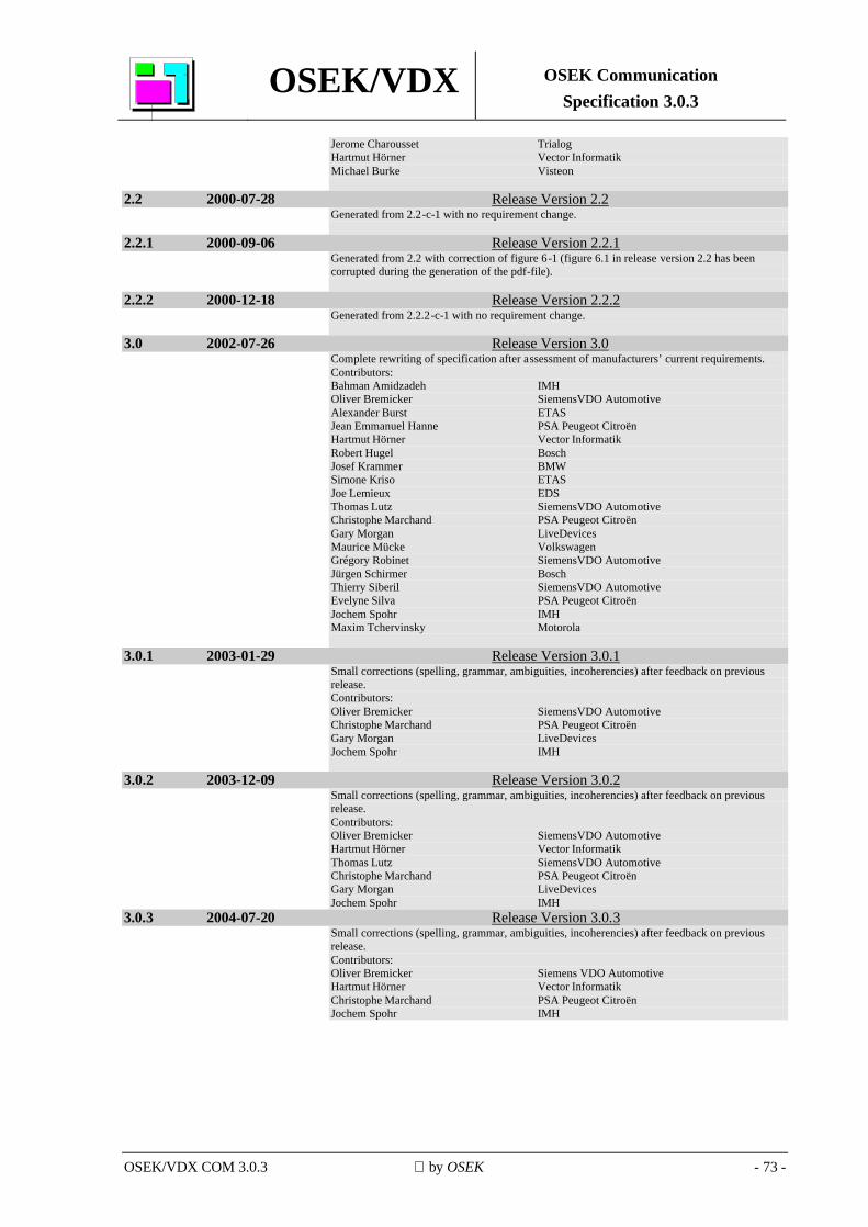
OSEK/VDX OSEK Communication Specification 3.0.3
OSEK/VDX COM 3.0.3 by OSEK - 73 -
Jerome Charousset Trialog Hartmut Hörner Vector Informatik Michael Burke Visteon
2.2 2000-07-28 Release Version 2.2 Generated from 2.2-c-1 with no requirement change.
2.2.1 2000-09-06 Release Version 2.2.1 Generated from 2.2 with correction of figure 6-1 (figure 6.1 in release version 2.2 has been corrupted during the generation of the pdf-file).
2.2.2 2000-12-18 Release Version 2.2.2 Generated from 2.2.2-c-1 with no requirement change.
3.0 2002-07-26 Release Version 3.0 Complete rewriting of specification after assessment of manufacturers’ current requirements. Contributors: Bahman Amidzadeh IMH Oliver Bremicker SiemensVDO Automotive Alexander Burst ETAS Jean Emmanuel Hanne PSA Peugeot Citroën Hartmut Hörner Vector Informatik Robert Hugel Bosch Josef Krammer BMW Simone Kriso ETAS Joe Lemieux EDS Thomas Lutz SiemensVDO Automotive Christophe Marchand PSA Peugeot Citroën Gary Morgan LiveDevices Maurice Mücke Volkswagen Grégory Robinet SiemensVDO Automotive Jürgen Schirmer Bosch Thierry Siberil SiemensVDO Automotive Evelyne Silva PSA Peugeot Citroën Jochem Spohr IMH Maxim Tchervinsky Motorola
3.0.1 2003-01-29 Release Version 3.0.1 Small corrections (spelling, grammar, ambiguities, incoherencies) after feedback on previous release. Contributors: Oliver Bremicker SiemensVDO Automotive Christophe Marchand PSA Peugeot Citroën Gary Morgan LiveDevices Jochem Spohr IMH
3.0.2 2003-12-09 Release Version 3.0.2 Small corrections (spelling, grammar, ambiguities, incoherencies) after feedback on previous release. Contributors: Oliver Bremicker SiemensVDO Automotive Hartmut Hörner Vector Informatik Thomas Lutz SiemensVDO Automotive Christophe Marchand PSA Peugeot Citroën Gary Morgan LiveDevices Jochem Spohr IMH
3.0.3 2004-07-20 Release Version 3.0.3 Small corrections (spelling, grammar, ambiguities, incoherencies) after feedback on previous release. Contributors: Oliver Bremicker Siemens VDO Automotive Hartmut Hörner Vector Informatik Christophe Marchand PSA Peugeot Citroën Jochem Spohr IMH