Embed Size (px)
Citation preview
Page | 1 The information in this document is subject to change without notice and should not be construed as a commitment by PCI Geomatics.
PCI Geomatics assumes no responsibility for any errors that may appear in this document.
OrthoEngine – Extracting a DEM from ASTER Data Geomatica 2014 Tutorial
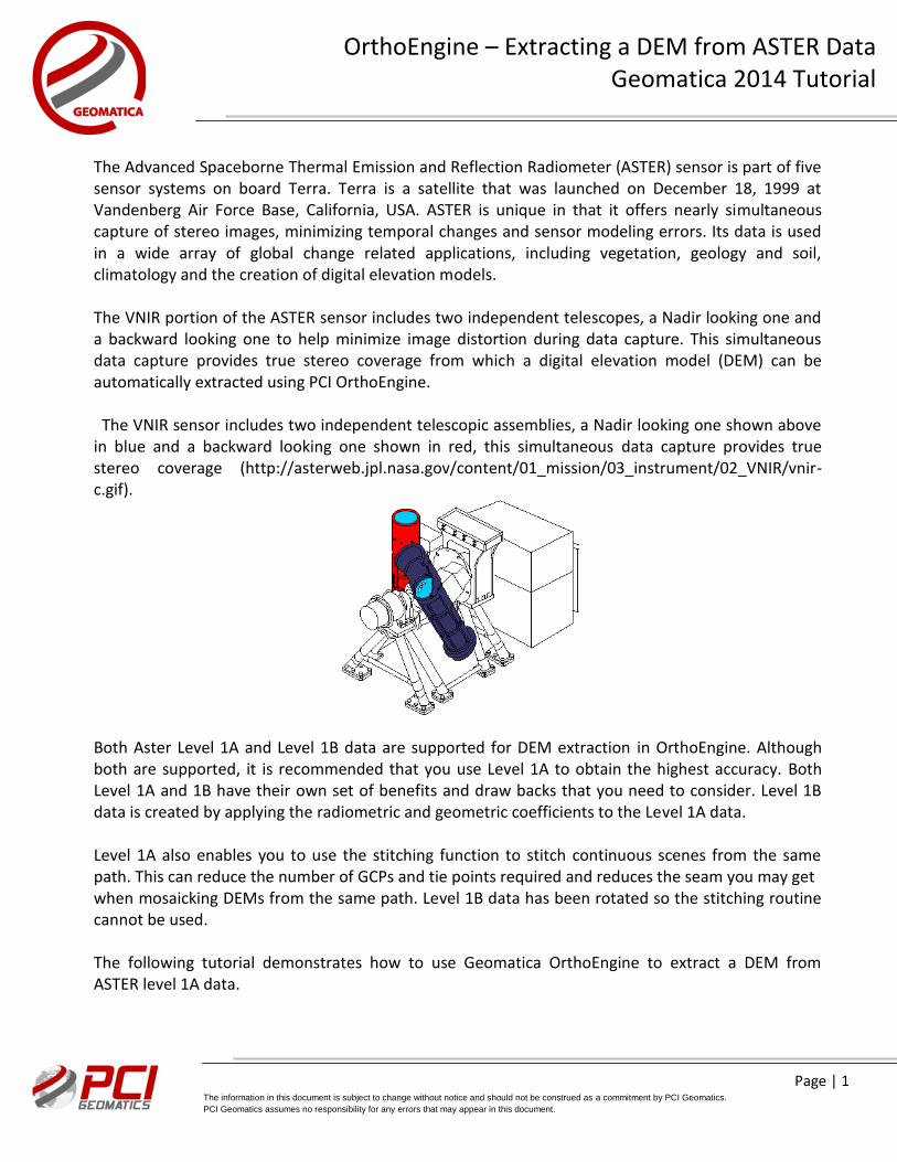
The Advanced Spaceborne Thermal Emission and Reflection Radiometer (ASTER) sensor is part of five sensor systems on board Terra. Terra is a satellite that was launched on December 18, 1999 at Vandenberg Air Force Base, California, USA. ASTER is unique in that it offers nearly simultaneous capture of stereo images, minimizing temporal changes and sensor modeling errors. Its data is used in a wide array of global change related applications, including vegetation, geology and soil, climatology and the creation of digital elevation models. The VNIR portion of the ASTER sensor includes two independent telescopes, a Nadir looking one and a backward looking one to help minimize image distortion during data capture. This simultaneous data capture provides true stereo coverage from which a digital elevation model (DEM) can be automatically extracted using PCI OrthoEngine. The VNIR sensor includes two independent telescopic assemblies, a Nadir looking one shown above in blue and a backward looking one shown in red, this simultaneous data capture provides true stereo coverage (http://asterweb.jpl.nasa.gov/content/01_mission/03_instrument/02_VNIR/vnir-c.gif). Both Aster Level 1A and Level 1B data are supported for DEM extraction in OrthoEngine. Although both are supported, it is recommended that you use Level 1A to obtain the highest accuracy. Both Level 1A and 1B have their own set of benefits and draw backs that you need to consider. Level 1B data is created by applying the radiometric and geometric coefficients to the Level 1A data. Level 1A also enables you to use the stitching function to stitch continuous scenes from the same path. This can reduce the number of GCPs and tie points required and reduces the seam you may get when mosaicking DEMs from the same path. Level 1B data has been rotated so the stitching routine cannot be used. The following tutorial demonstrates how to use Geomatica OrthoEngine to extract a DEM from ASTER level 1A data.
Page | 2 The information in this document is subject to change without notice and should not be construed as a commitment by PCI Geomatics.
PCI Geomatics assumes no responsibility for any errors that may appear in this document.
OrthoEngine – Extracting a DEM from ASTER Data Geomatica 2014 Tutorial
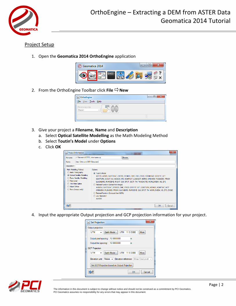
Project Setup
1. Open the Geomatica 2014 OrthoEngine application
2. From the OrthoEngine Toolbar click File New
3. Give your project a Filename, Name and Description a. Select Optical Satellite Modelling as the Math Modeling Method b. Select Toutin’s Model under Options c. Click OK
4. Input the appropriate Output projection and GCP projection information for your project.
Page | 3 The information in this document is subject to change without notice and should not be construed as a commitment by PCI Geomatics.
PCI Geomatics assumes no responsibility for any errors that may appear in this document.
OrthoEngine – Extracting a DEM from ASTER Data Geomatica 2014 Tutorial
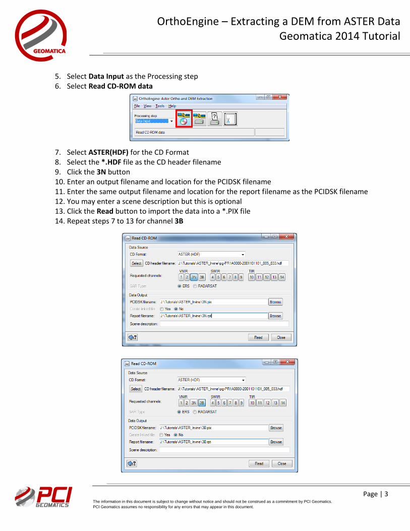
5. Select Data Input as the Processing step 6. Select Read CD-ROM data
7. Select ASTER(HDF) for the CD Format 8. Select the *.HDF file as the CD header filename 9. Click the 3N button 10. Enter an output filename and location for the PCIDSK filename 11. Enter the same output filename and location for the report filename as the PCIDSK filename 12. You may enter a scene description but this is optional 13. Click the Read button to import the data into a *.PIX file 14. Repeat steps 7 to 13 for channel 3B
Page | 4 The information in this document is subject to change without notice and should not be construed as a commitment by PCI Geomatics.
PCI Geomatics assumes no responsibility for any errors that may appear in this document.
OrthoEngine – Extracting a DEM from ASTER Data Geomatica 2014 Tutorial
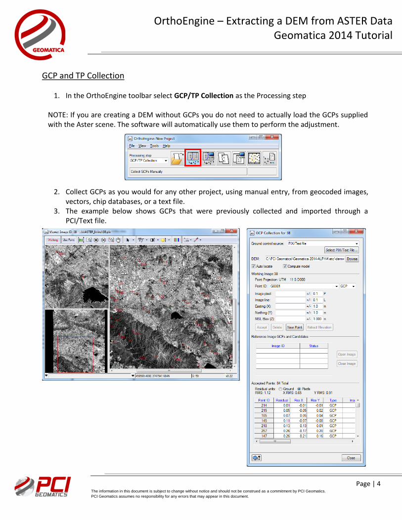
GCP and TP Collection
1. In the OrthoEngine toolbar select GCP/TP Collection as the Processing step
NOTE: If you are creating a DEM without GCPs you do not need to actually load the GCPs supplied with the Aster scene. The software will automatically use them to perform the adjustment.
2. Collect GCPs as you would for any other project, using manual entry, from geocoded images, vectors, chip databases, or a text file.
3. The example below shows GCPs that were previously collected and imported through a PCI/Text file.
Page | 5 The information in this document is subject to change without notice and should not be construed as a commitment by PCI Geomatics.
PCI Geomatics assumes no responsibility for any errors that may appear in this document.
OrthoEngine – Extracting a DEM from ASTER Data Geomatica 2014 Tutorial
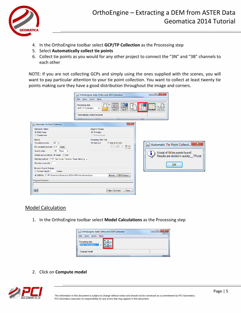
4. In the OrthoEngine toolbar select GCP/TP Collection as the Processing step 5. Select Automatically collect tie points 6. Collect tie points as you would for any other project to connect the “3N” and “3B” channels to
each other NOTE: If you are not collecting GCPs and simply using the ones supplied with the scenes, you will want to pay particular attention to your tie point collection. You want to collect at least twenty tie points making sure they have a good distribution throughout the image and corners.
Model Calculation
1. In the OrthoEngine toolbar select Model Calculations as the Processing step
2. Click on Compute model
Page | 6 The information in this document is subject to change without notice and should not be construed as a commitment by PCI Geomatics.
PCI Geomatics assumes no responsibility for any errors that may appear in this document.
OrthoEngine – Extracting a DEM from ASTER Data Geomatica 2014 Tutorial
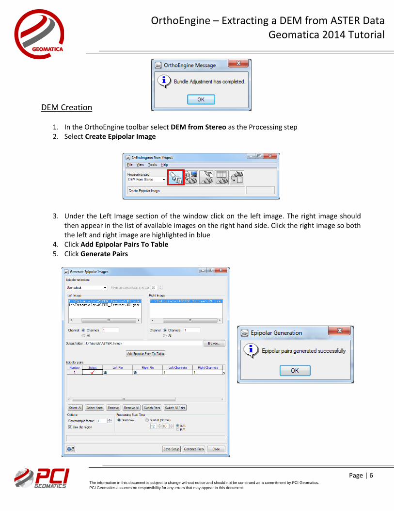
DEM Creation
1. In the OrthoEngine toolbar select DEM from Stereo as the Processing step 2. Select Create Epipolar Image
3. Under the Left Image section of the window click on the left image. The right image should then appear in the list of available images on the right hand side. Click the right image so both the left and right image are highlighted in blue
4. Click Add Epipolar Pairs To Table 5. Click Generate Pairs
Page | 7 The information in this document is subject to change without notice and should not be construed as a commitment by PCI Geomatics.
PCI Geomatics assumes no responsibility for any errors that may appear in this document.
OrthoEngine – Extracting a DEM from ASTER Data Geomatica 2014 Tutorial
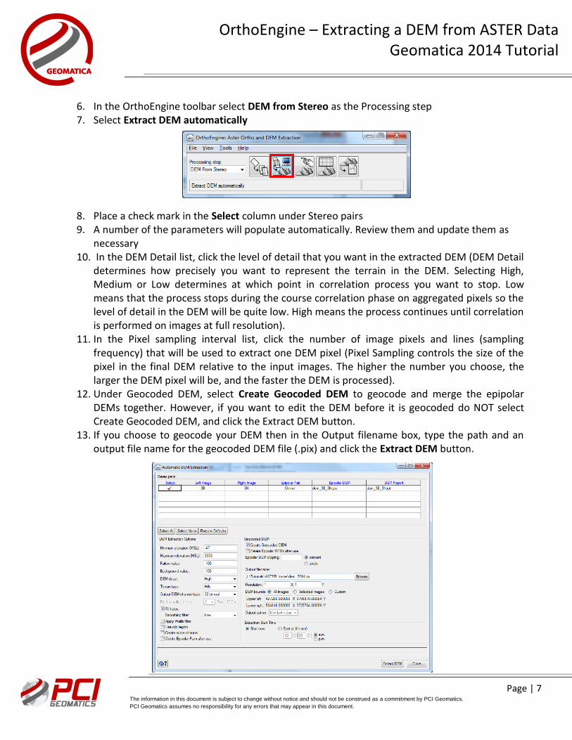
6. In the OrthoEngine toolbar select DEM from Stereo as the Processing step 7. Select Extract DEM automatically
8. Place a check mark in the Select column under Stereo pairs 9. A number of the parameters will populate automatically. Review them and update them as
necessary 10. In the DEM Detail list, click the level of detail that you want in the extracted DEM (DEM Detail
determines how precisely you want to represent the terrain in the DEM. Selecting High, Medium or Low determines at which point in correlation process you want to stop. Low means that the process stops during the course correlation phase on aggregated pixels so the level of detail in the DEM will be quite low. High means the process continues until correlation is performed on images at full resolution).
11. In the Pixel sampling interval list, click the number of image pixels and lines (sampling frequency) that will be used to extract one DEM pixel (Pixel Sampling controls the size of the pixel in the final DEM relative to the input images. The higher the number you choose, the larger the DEM pixel will be, and the faster the DEM is processed).
12. Under Geocoded DEM, select Create Geocoded DEM to geocode and merge the epipolar DEMs together. However, if you want to edit the DEM before it is geocoded do NOT select Create Geocoded DEM, and click the Extract DEM button.
13. If you choose to geocode your DEM then in the Output filename box, type the path and an output file name for the geocoded DEM file (.pix) and click the Extract DEM button.
Page | 8 The information in this document is subject to change without notice and should not be construed as a commitment by PCI Geomatics.
PCI Geomatics assumes no responsibility for any errors that may appear in this document.
OrthoEngine – Extracting a DEM from ASTER Data Geomatica 2014 Tutorial
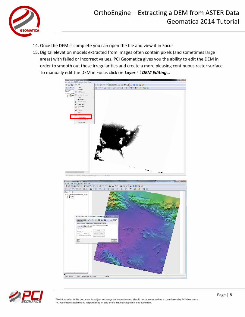
14. Once the DEM is complete you can open the file and view it in Focus
15. Digital elevation models extracted from images often contain pixels (and sometimes large
areas) with failed or incorrect values. PCI Geomatica gives you the ability to edit the DEM in
order to smooth out these irregularities and create a more pleasing continuous raster surface.
To manually edit the DEM in Focus click on Layer DEM Editing…