Embed Size (px)
Citation preview
page 1
201/203 SERIES201/203 SERIES201/203 SERIES201/203 SERIES201/203 SERIESFLOWMETERS/CONTROLLERSFLOWMETERS/CONTROLLERSFLOWMETERS/CONTROLLERSFLOWMETERS/CONTROLLERSFLOWMETERS/CONTROLLERS
HASTINGS INSTRUCTION
MANUAL

page 2
Manual Print HistoryManual Print HistoryManual Print HistoryManual Print HistoryManual Print History
The print history shown below lists the printing dates of all revisions and addenda created for thismanual. The revision level letter increases alphabetically as the manual undergoes subsequentupdates. Addenda, which are released between revisions, contain important change information thatthe user should incorporate immediately into the manual. Addenda are numbered sequentially.When a new revision is created, all addenda associated with the previous revision of the manual areincorporated into the new revision of the manual. Each new revision includes a revised copy of thisprint history page.
Revision A (Document Number 141-0999) ...........................................................September 1999
Revision B (Document Number 141-1199) ...........................................................November 1999
Hastings Instruments reserves the right to change or modify the design of its equipment withoutany obligation to provide notification of change or intent to change.
page 3
TTTTTable of Contentsable of Contentsable of Contentsable of Contentsable of Contents1.01.01.01.01.0 GENERAL INFORMAGENERAL INFORMAGENERAL INFORMAGENERAL INFORMAGENERAL INFORMATIONTIONTIONTIONTION ................................................................................................................................................................................................................................................................................................................. 555551.1 Features ...............................................................................................................................5
1.2 Specifications .......................................................................................................................6
1.3 Optional 4-20 mA Current Output ......................................................................................7
1.4 Other Accessories .................................................................................................................7
2.02.02.02.02.0 INSTINSTINSTINSTINSTALLAALLAALLAALLAALLATION and OPERATION and OPERATION and OPERATION and OPERATION and OPERATIONTIONTIONTIONTION ........................................................................................................................................................................................................................................... 999992.1 Receiving Inspection ............................................................................................................9
2.2 Power Requirements .............................................................................................................9
2.3 Output Signal .......................................................................................................................9
2.4 Mechanical Connections .......................................................................................................9
2.5 Electrical Connections ........................................................................................................10
2.6 Operation ...........................................................................................................................11
2.7 Range Changing ................................................................................................................12
3.03.03.03.03.0 THEORTHEORTHEORTHEORTHEORY OF OPERAY OF OPERAY OF OPERAY OF OPERAY OF OPERATIONTIONTIONTIONTION ................................................................................................................................................................................................................................................................................................................. 1 51 51 51 51 53.1 Overall Functional Description ...........................................................................................15
3.2 Sensor ................................................................................................................................15
3.3 Electronics .........................................................................................................................15
3.4 Shunt .................................................................................................................................16
3.5 Valve ..................................................................................................................................17
4.04.04.04.04.0 MAINTENANCEMAINTENANCEMAINTENANCEMAINTENANCEMAINTENANCE ................................................................................................................................................................................................................................................................................................................................................................................................................1 91 91 91 91 94.1 Authorized Maintenance ....................................................................................................19
4.2 Troubleshooting .................................................................................................................19
4.3 Adjustments .......................................................................................................................20
4.4 End Cap Removal ..............................................................................................................21
4.5 Printed Circuit Board Replacement ....................................................................................21
4.6 Sensor Replacement ...........................................................................................................21
4.7 Orifice Changes .................................................................................................................21
4.8 Replacement Parts ..............................................................................................................23
5.05.05.05.05.0 WWWWWARRANTY and REPARRANTY and REPARRANTY and REPARRANTY and REPARRANTY and REPAIRAIRAIRAIRAIR................................................................................................................................................................................................................................................................................................................................ 2 52 52 52 52 55.1 Warranty Policy ..................................................................................................................25
5.2 Non-Warranty Repair Policy ..............................................................................................25
6.06.06.06.06.0 DRADRADRADRADRAWINGS and REFERENCESWINGS and REFERENCESWINGS and REFERENCESWINGS and REFERENCESWINGS and REFERENCES .................................................................................................................................................................................................................................................................... 2 72 72 72 72 7

page 4
page 5
General Information
SECTION 1
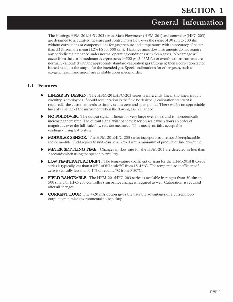
The Hastings HFM-201/HFC-203 series Mass Flowmeter (HFM-201) and controller (HFC-203)are designed to accurately measure and control mass flow over the range of 30 slm to 500 slm,without corrections or compensations for gas pressure and temperature with an accuracy of betterthan ±1% from the mean (±2% FS for 500 slm). Hastings mass flow instruments do not requireany periodic maintenance under normal operating conditions with clean gases. No damage willoccur from the use of moderate overpressures (~500 psi/3.45MPa) or overflows. Instruments arenormally calibrated with the appropriate standard calibration gas (nitrogen) then a correction factoris used to adjust the output for the intended gas. Special calibrations for other gases, such asoxygen, helium and argon, are available upon special order.
1.1 Features
LINEAR BY DESIGNLINEAR BY DESIGNLINEAR BY DESIGNLINEAR BY DESIGNLINEAR BY DESIGN..... The HFM-201/HFC-203 series is inherently linear (no linearizationcircuitry is employed). Should recalibration in the field be desired (a calibration standard isrequired), the customer needs to simply set the zero and span points. There will be no appreciablelinearity change of the instrument when the flowing gas is changed.
NO FOLDONO FOLDONO FOLDONO FOLDONO FOLDOVER.VER.VER.VER.VER. The output signal is linear for very large over flows and is monotonicallyincreasing thereafter. The output signal will not come back on scale when flows an order ofmagnitude over the full scale flow rate are measured. This means no false acceptablereadings during leak testing.
MODULAR SENSOR.MODULAR SENSOR.MODULAR SENSOR.MODULAR SENSOR.MODULAR SENSOR. The HFM-201/HFC-203 series incorporates a removable/replaceablesensor module. Field repairs to units can be achieved with a minimum of production line downtime.
METER SETTLING METER SETTLING METER SETTLING METER SETTLING METER SETTLING TIME.TIME.TIME.TIME.TIME. Changes in flow rate for the HFM-201 are detected in less than2 seconds when using the speed up circuitry.
LOLOLOLOLOW W W W W TEMPERATEMPERATEMPERATEMPERATEMPERATURE DRIFTTURE DRIFTTURE DRIFTTURE DRIFTTURE DRIFT..... The temperature coefficient of span for the HFM-201/HFC-203series is typically less than 0.05% of full scale/°C from 15-45°C. The temperature coefficient ofzero is typically less than 0.1 % of reading/°C from 0-50°C.
FIELD RANGEABLE.FIELD RANGEABLE.FIELD RANGEABLE.FIELD RANGEABLE.FIELD RANGEABLE. The HFM-201/HFC-203 series is available in ranges from 30 slm to500 slm. For HFC-203 controller�s, an orifice change is required as well. Calibration, is requiredafter all changes.
CURRENT LOOPCURRENT LOOPCURRENT LOOPCURRENT LOOPCURRENT LOOP..... The 4-20 mA option gives the user the advantages of a current loopoutput to minimize environmental noise pickup.
page 6
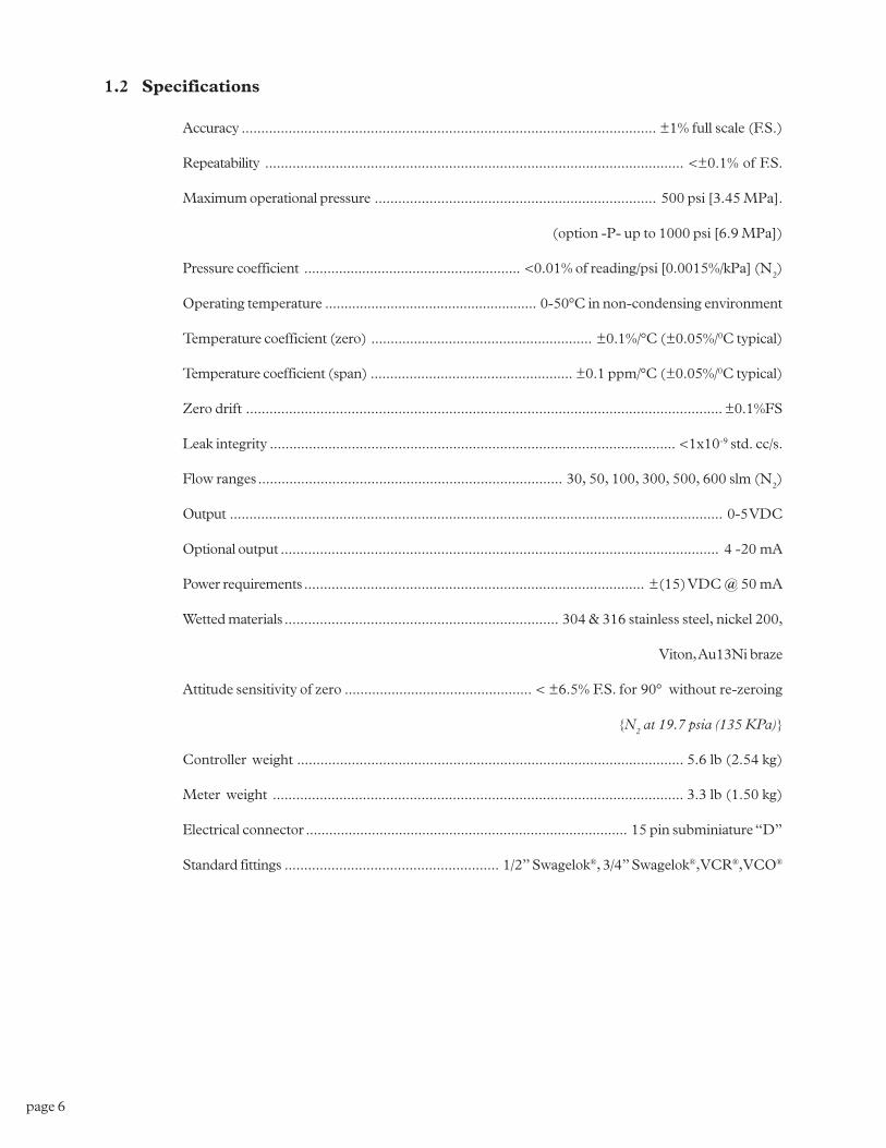
1.2 Specifications
Accuracy .......................................................................................................... ±1% full scale (F.S.)
Repeatability ........................................................................................................... <±0.1% of F.S.
Maximum operational pressure ........................................................................ 500 psi [3.45 MPa].
(option -P- up to 1000 psi [6.9 MPa])
Pressure coefficient ........................................................ <0.01% of reading/psi [0.0015%/kPa] (N2)
Operating temperature ....................................................... 0-50°C in non-condensing environment
Temperature coefficient (zero) ......................................................... ±0.1%/°C (±0.05%/0C typical)
Temperature coefficient (span) .................................................... ±0.1 ppm/°C (±0.05%/0C typical)
Zero drift .......................................................................................................................... ±0.1%FS
Leak integrity ........................................................................................................ <1x10⁻⁹ std. cc/s.
Flow ranges .............................................................................. 30, 50, 100, 300, 500, 600 slm (N2)
Output .............................................................................................................................. 0-5 VDC
Optional output ................................................................................................................ 4 -20 mA
Power requirements ....................................................................................... ±(15) VDC @ 50 mA
Wetted materials ...................................................................... 304 & 316 stainless steel, nickel 200,
Viton, Au13Ni braze
Attitude sensitivity of zero ................................................ < ±6.5% F.S. for 90° without re-zeroing
{N2 at 19.7 psia (135 KPa)}
Controller weight ................................................................................................... 5.6 lb (2.54 kg)
Meter weight ......................................................................................................... 3.3 lb (1.50 kg)
Electrical connector ................................................................................... 15 pin subminiature �D�
Standard fittings ....................................................... 1/2� Swagelok®, 3/4� Swagelok®, VCR®, VCO®
page 7
1.3 Optional 4-20 mA Current Output
An option to the standard 0-5 VDC output is the 4-20 mA current output that is proportional toflow. The 4 - 20 mA signal is produced from the 0 - 5 VDC output of the flowmeter. The currentloop output is useful for remote applications where pickup noise could substantially affect thestability of the voltage output.
The current loop signal replaces the voltage output on pin 6 of the �D� connector. The currentloop may be returned to either the power supply ground or the -15 VDC connection on the powersupply. If the current loop is returned to the power supply ground, the load must be between 0 and600 ohm. If it is returned to the -15VDC, the load must be between 600 and 1200 ohm. Failureto meet these conditions will cause failure of the loop transmitter.
The 4-20 mA I/O option can accept a current input. The 0-5 VDC command signal on pin 14 canbe replaced by a 4-20mA command signal. The loop presets an impedance of 75 ohms and isreturned to the power supply through the valve common.
1.4 Other Accessories
1.4.1 1.4.1 1.4.1 1.4.1 1.4.1 TTTTTotalizer (TR-1J)otalizer (TR-1J)otalizer (TR-1J)otalizer (TR-1J)otalizer (TR-1J)
The Hastings Flow Totalizer integrates the 0-5 VDC signal generated by the flowmeter to give atotal flow reading. Count rates from 0 to 999 counts per minute are selectable by internal setting.
1.4.2 Hastings Model 40/200/400 P1.4.2 Hastings Model 40/200/400 P1.4.2 Hastings Model 40/200/400 P1.4.2 Hastings Model 40/200/400 P1.4.2 Hastings Model 40/200/400 Pooooowwwwwer Supplyer Supplyer Supplyer Supplyer Supply
Hastings power supplies are available in either two or four channel versions. They convert 115 or230VAC to the ±15 VDC required to operate the flowmeter. Interface terminals for the ±15 VDCinput and the 0-5 VDC linear output signal are located on the rear of the panel. Also, a cable canbe supplied with the power supply that provides the +15 VDC on pin 11 of a 15-pin �D� connectorand the 0 - 5VDC output measurement on pin 6. Pins 5, 7 and 12 are common, and pin 7 ischassis ground. Throughout this manual, when reference is made to a power supply, it is assumedthe customer is using a Hastings Model 200/400/40 supply. Hastings power supplies do not meetCE standards at this time.

page 8
page 9
This section contains the necessary steps to assist in getting a new flowmeter/controller intooperation as quickly and easily as possible. Please read the following thoroughly before attempt-ing to install the instrument.
2.1 Receiving Inspection
Carefully unpack the Hastings 201/203 series instrument and any accessories that have also beenordered. Inspect for any obvious signs of damage to the shipment. Immediately advise the carrierwho delivered the shipment if any damage is suspected. Check each component shipped with thepacking list. Insure that all parts are present (i.e., flowmeter, power supply, cables, etc.). Optionalequipment or accessories will be listed separately on the packing list. There may also be one ormore OPT-options on the packing list. These normally refer to special ranges or special gascalibrations. They may also refer to special helium leak tests, or high pressure tests. In most cases,these are not separate parts, but special options or modifications built into the flowmeter.
2.2 Power Requirements
The HFM-201/HFC-203 series requires ±15 VDC @ ±50 mA (HFM-201) +50 mA, -200 mA(HFC-203)for proper operation. The supply voltage should be sufficiently regulated to no morethan 50 mV ripple. The supply voltage can vary from 14.0 to 16.0 VDC. Surge suppressors arerecommended to prevent power spikes reaching the instrument. The Hastings power supplydescribed in Section 1.4.2 satisfies these power requirements.
The HFM-201/HFC-203 series instruments have an integral 5 VDC ref. source. This stablevoltage is on pin 15 of the �D� connector and may be used for the command voltage on thecontroller (HFC-203).
2.3 Output Signal
The standard output of the flowmeter is a 0-5 VDC signal proportional to the flow rate. In theHastings power supply the output is routed to the display, and is also available at the terminals onthe rear panel. If a Hastings supply is not used, the output is available on pin 6 of the �D� connec-tor and is referenced to pin 5. It is recommended that the load resistance be no less that 2kW. Ifthe optional 4-20 mA output is used, the load impedance must be selected in accordance withSection 1.3.
2.4 Mechanical Connections
The flowmeter may be mounted in any position as long as the direction of gas flow through theinstrument follows the arrow marked on the bottom of the flowmeter case label. The preferredorientation is with the inlet and outlet fittings in a horizontal plane (if operating with a dense gas orat high pressures the instrument must be installed horizontally). When mounted in a differentorientation the instrument should be re-zeroed at zero flow with the system pressurized to theexpected operating pressure.
The smallest of the internal passageways in the 201/203 series is the diameter of the sensor tube,which is 0.0125�(0.31 mm), so the instrument requires adequate filtering of the gas supply toprevent blockage or clogging of the tube.
SECTION 2Installation and Operation
page 10
The pressure regulator and the plumbing upstream must be of sufficient size to minimize changesin the upstream pressure. When switching from full flow to zero flow, the inlet pressure of instru-ment should rise to no more that 30% above the inlet pressure at full flow. In general, highcapacity regulators and large internal diameter plumbing help to make the system more stable. Thepressure drop between the regulator and the instrument due to line resistance should be minimized.The differential pressure across the unit should be less than 6� of H2O at maximum flow.
There are two 8-32 threaded holes, 0.25� deep, located on the bottom of the base that can be usedto secure it to a mounting bracket, if desired (screws provided). Other holes for special mountingcan be added to the end cap as desired.
The standard inlet and outlet fittings for the 201/203 are 0.5� and 0.75� Swagelok (optional VCRor VCO fittings). The O-rings for the end cap and the sensor are Viton (optional Kalrez or Neo-prene). It is suggested that all connections be checked for leaks after installation. This can be doneby pressurizing the instrument (do not exceed 500 psig unless the flowmeter is specifically rated forhigher pressures) and applying a diluted soap solution to the flow connections rated for higherpressures) and applying a diluted soap solution to the flow connections.
2.5 Electrical Connections
If a power supply from Hastings Instruments is used, installation consists of connecting the HFM-201/HFC-203 series cable from the �D� connector on the rear of the power supply to the �D�connector on the top of the flowmeter. If a different power supply is used, follow the instructionsbelow when connecting the flow meter.
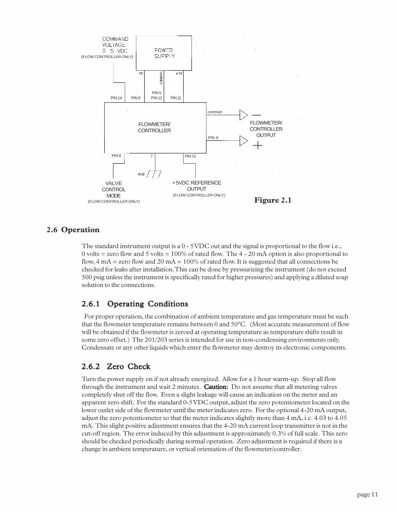
This HFM-201/HFC-203 series requires Hastings cable #AF-8AM. Use of any other cable canseverely damage the instrument and void the warranty. Figure 2.1 shows the schematic layout forconnecting the instrument to an appropriate power supply.
The power supply used must be capable of supplying +15VDC at 50mA and -15VDC at -200mAfor each controller. These voltages must be referenced to a common ground. Connect -15VDC topin 9 and +15VDC to pin 11. Pins 5 and 12 are both commons and they must be connectedtogether and to the ground connection at the power supply. Do not connect them together at theflow controller as the resulting crosstalk could result in flow instabilities. Pin 7 is the case ground.It should be connected to the cable shield if available and to the AC ground to the power supply.
Pin 6 is the output signal from the flow controller. This output will be 0-5VDC, 5VDC being 100%of rated or full flow. Pin 14 is the command input. This should be a 0-5VDC signal and must befree of spikes or other electrical noise, as these will generate false flow commands that the controllerwould attempt to flow. Pin 15 is a well regulated +5.00VDC output reference. The reference isdesigned to provide the command signal for pin 14 by connecting one end of a potentiometer topin 15 and the other end to ground. The center lead would then be connected to pin 14.
If a valve override switch is not desired, the unit is ready for use at this time. If the override switchis desired, connect the center pin of a single pole, three-position switch with the center off positionto pin 8. Connect +15VDC to one end of the switch, and -15VDC to the other end. This will resultin the valve being full open when +15VDC is supplied to pin 8, off when -15VDC is supplied andauto-control when there is no connection to pin 8 (OPEN-AUTO-CLOSE). This setup will beadequate for most purposes, but there will be a small delay for capacitors to charge between switchoperation and control override.
page 11
2.6 Operation
The standard instrument output is a 0 - 5 VDC out and the signal is proportional to the flow i.e.,0 volts = zero flow and 5 volts = 100% of rated flow. The 4 - 20 mA option is also proportional toflow, 4 mA = zero flow and 20 mA = 100% of rated flow. It is suggested that all connections bechecked for leaks after installation. This can be done by pressurizing the instrument (do not exceed500 psig unless the instrument is specifically rated for higher pressures) and applying a diluted soapsolution to the connections.
2.6.1 Operating Conditions2.6.1 Operating Conditions2.6.1 Operating Conditions2.6.1 Operating Conditions2.6.1 Operating Conditions
For proper operation, the combination of ambient temperature and gas temperature must be suchthat the flowmeter temperature remains between 0 and 50°C. (Most accurate measurement of flowwill be obtained if the flowmeter is zeroed at operating temperature as temperature shifts result insome zero offset.) The 201/203 series is intended for use in non-condensing environments only.Condensate or any other liquids which enter the flowmeter may destroy its electronic components.
2.6.2 Zero Check2.6.2 Zero Check2.6.2 Zero Check2.6.2 Zero Check2.6.2 Zero Check
Turn the power supply on if not already energized. Allow for a 1 hour warm-up. Stop all flowthrough the instrument and wait 2 minutes. Caution:Caution:Caution:Caution:Caution: Do not assume that all metering valvescompletely shut off the flow. Even a slight leakage will cause an indication on the meter and anapparent zero shift. For the standard 0-5 VDC output, adjust the zero potentiometer located on thelower outlet side of the flowmeter until the meter indicates zero. For the optional 4-20 mA output,adjust the zero potentiometer so that the meter indicates slightly more than 4 mA, i.e. 4.03 to 4.05mA. This slight positive adjustment ensures that the 4-20 mA current loop transmitter is not in thecut-off region. The error induced by this adjustment is approximately 0.3% of full scale. This zeroshould be checked periodically during normal operation. Zero adjustment is required if there is achange in ambient temperature, or vertical orientation of the flowmeter/controller.
Figure 2.1
PIN 14 PIN 9 PIN 12 PIN 11
common
PIN 6
PIN 8 7 PIN 15
+ 5VDC REFERENCEOUTPUT
VALVECONTROL
MODE
FLOWMETER/CONTROLLER
OUTPUT
PIN 5
(FLOW CONTROLLER ONLY)
(FLOW CONTROLLER ONLY)
(FLOW CONTROLLER ONLY)
FLOWMETER/CONTROLLER
page 12
Maintainance and Repair 4-3
2.6.3 High Pressure Operation2.6.3 High Pressure Operation2.6.3 High Pressure Operation2.6.3 High Pressure Operation2.6.3 High Pressure Operation
When operating at high pressure, the increased density of gas will cause natural convection to flowthrough the sensor tube if the instrument is not mounted in a level position. This natural convec-tion flow will be proportional to the system pressure. This will be seen as a shift in the zero flowoutput that is directly proportional to the system pressure.
2.6.4 Blending of Gases2.6.4 Blending of Gases2.6.4 Blending of Gases2.6.4 Blending of Gases2.6.4 Blending of Gases
In the blending of two gases, it is possible to maintain a fixed ratio of one gas to another. In thiscase, the output of one flow controller is used as the reference voltage for the set point potentiom-eter of a second flow controller. The set point potentiometer then provides a control signal that isproportional to the output signal of the first flow controller, and hence controls the flow rate of thesecond gas as a percentage of the flow rate of the first gas.
EXAMPLE:EXAMPLE:EXAMPLE:EXAMPLE:EXAMPLE: Flow controller A has 0-100 slpm range with a 5.00 volt output at full scale. Flowcontroller B has 0-10 slpm range with a 5.00 volt output at full scale. If flow controller A is set at80 slpm, its output voltage would be 4.00 volts (80 slpm/100 slpm x 5.00 volts = 4.00 volts). Ifthe output signal from flow controller A is connected to the command potentiometer of flowcontroller B, it then becomes a variable reference voltage for flow controller B proportional to theflow rate of flow controller A.
If the set point potentiometer of flow controller B is set at 50% of full scale, and the referencevoltage from flow controller A is 4.00, then the command signal going to flow controller B wouldbe 2.00 volts (4.00 volts x 50.0% = 2.00 volts). The flow of gas through flow controller B is thencontrolled at 4 slpm (2.00 volts/5.00 volts x 10 slpm = 4 slpm).
The ratio of the two gases is 20:1 (80 slpm/4slpm). The % mixture of gas A is 95.2 (80slpm/84slpm and the % mixture of gas B is 4.8% (4 slpm/84 slpm).
Should the flow of flow controller A drop to 78 slpm, flow controller B would drop to 3.9 slpm,hence maintaining the same ratio of the mixture. (78 slpm/100slpm x 5v = 3.90v x 50% = 1.95v;1.95v/5.00v x 10 slpm = 3.9 slpm; 78 slpm:3.9 slpm = 20:1)
2.7 Operation
2.7.1 Opera2.7.1 Opera2.7.1 Opera2.7.1 Opera2.7.1 Operation with a Hastings potion with a Hastings potion with a Hastings potion with a Hastings potion with a Hastings powwwwwer supplyer supplyer supplyer supplyer supply.....
There are two controls for each flow controller connected to a Hastings power supply. A switchlabeled �OPEN; AUTO; CLOSED� (valve over ride) and a potentiometer knob labeled �COM-MAND�. For normal operation, the valve over ride switch will be in the �AUTO� position. The�CLOSE� position removes all power from the valve, shutting off flow regardless of the commandpot setting. The �OPEN� position applies full available valve voltage to the valve, causing it toopen, regardless of the command pot setting. The �OPEN� position is useful for purging systems.It is recommended that the valve over ride switch not be left in this position for extended periods oftime, with no flow through the controller, as a small positive zero shift may be observed.
The �COMMAND� pot adjusts the 0-5 VDC command signal sent to the flow controller. Thesetting for each controller connected to the power supply can be observed by rotating the�POWER/CHANNEL SELECT� knob to the channel connected to the controller that you wishto observe, and rotating the �FLOW/COMMAND� knob to �COMMAND�. The display willthen indicate the command signal. (Depending on how the power supply was set up, the displaycould indicate in flow units or percent of full scale.) To observe the flow output of the flow control-ler, rotate the �FLOW/COMMAND� knob to �FLOW�. The display will now indicate the flowoutput signal.
page 13
2.7.2 Operation with a power supply other than a Hastings.2.7.2 Operation with a power supply other than a Hastings.2.7.2 Operation with a power supply other than a Hastings.2.7.2 Operation with a power supply other than a Hastings.2.7.2 Operation with a power supply other than a Hastings.
The flow controller must be connected to the power source as specified in section 2.6. In general,a 0-5 VDC command signal proportional to the intended flow (0 volts = zero flow; 5 volts = 100%of rated flow) must be applied to pin 14 of the �D� connector. A 0-5 VDC signal proportional tothe flow rate through the instrument will be present on pin 6 of the �D� connector. The controlmode is selected via pin 8 of the �D� connector. Apply +15 volts for full open, -15 volts for closedand allow pin 8 to float for flow proportional to the command voltage. Refer to your power supplymanual for the specifics of implementing these parameters.
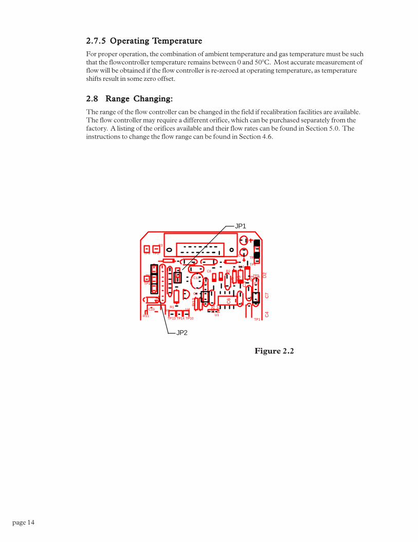
2.7.32.7.32.7.32.7.32.7.3 Operation with an external sensor. (Fig. 2.2)Operation with an external sensor. (Fig. 2.2)Operation with an external sensor. (Fig. 2.2)Operation with an external sensor. (Fig. 2.2)Operation with an external sensor. (Fig. 2.2)
In some instances, it might be desirable to use an external sensor to provide process information tothe control circuitry in the flow controller. For example, you might want to control the pressure ina vacuum system by adjusting the rate at which the system is backfilled with a gas. The new,enhanced HFC series of flowcontrollers have provision for accepting a 0-5VDC output from anexternal sensor at pin 13 of the �D� connector. To activate this feature, the cover of the HFC mustbe removed to gain access to PC-828 and move a jumper on JP1. JP1 is a three pin jumper blocklocated just below the �D� connector. In the normal operating mode, the jumper covers thebottom two pins. To select �External Sensor�, move the jumper to the upper two pins. This swapsthe flow input to the controller circuit from the flowmeter output to pin 13 of the �D� connector.
2.7.42.7.42.7.42.7.42.7.4 Response to Command ChangesResponse to Command ChangesResponse to Command ChangesResponse to Command ChangesResponse to Command Changes
The response of the control circuit to changes to the command signal is set at the factory for fast,stable response. Should it be necessary, the response is adjustable using the set of jumpers labeled�JP2�. JP2 is located at the upper left corner of PC-828. The pins are numbered 1-6, from top tobottom.
The fastest response to command changes is obtained when all six pins of JP2 are covered by thejumpers. This setup allows large overshoot and undershoot swings in the actual flow rate while thecontrol circuit is establishing control at the new command point. The slowest response to commandchanges is obtained when none of the pins of JP2 are covered by jumpers. This setup results in noovershoot or undershoot in the actual flow rate as the controller circuit establishes control at thenew command point.
To adjust the response, you need a means of producing a step change in the command voltagefrom 10% of full scale to 100% of full scale. Follow the steps outlined below:
1) Cover all six pins of JP2 with jumpers. (see fig. 2.2)
2) Set the command voltage to 10% of full scale. Allow the flow to stabilize.
3) Step change the command voltage to 100%, and observe the flow through the controller. Ifthe overshoot is too large, remove the jumper over pins 1 and 2. Reset the command voltageto 10%, and allow the controller to stabilize.
4) Step change the command voltage to 100%, and observe the flow through the controller.
If the overshoot is still too large:
a) Remove the jumpers over pins 3 and 4. Reset the command voltage to 10%, and allow thecontroller to stabilize.
b) Repeat the step change from 10% to 100%. If the overshoot is still too large, remove the lastjumper (pins 5 and 6). This is the �soft start� configuration.
If the response is too slow:
a) Replace the jumper over pins 1 and 2, and remove the jumper over pins 3 and 4. Reset thecommand voltage to 10%, and allow the controller to stabilize.
b) Repeat the step change from 10% to 100%. If the response is still too slow, replace the jumperover pins 3 and 4. This is the fast response configuration.
5) To prevent loss of the unused jumpers, place each one over one pin only on JP2.
page 14
2.7.5 Opera2.7.5 Opera2.7.5 Opera2.7.5 Opera2.7.5 Operating ting ting ting ting TTTTTemperaemperaemperaemperaemperaturetureturetureture
For proper operation, the combination of ambient temperature and gas temperature must be suchthat the flowcontroller temperature remains between 0 and 500C. Most accurate measurement offlow will be obtained if the flow controller is re-zeroed at operating temperature, as temperatureshifts result in some zero offset.
2.8 Range Changing:2.8 Range Changing:2.8 Range Changing:2.8 Range Changing:2.8 Range Changing:
The range of the flow controller can be changed in the field if recalibration facilities are available.The flow controller may require a different orifice, which can be purchased separately from thefactory. A listing of the orifices available and their flow rates can be found in Section 5.0. Theinstructions to change the flow range can be found in Section 4.6.
C10
C11
R12
C2
C13JP1
D3
D5
R20R1
D2
D1
R3
C3
C1C6
U1
R5
U4
TP11
TP2TP8
R23
TP1
C9
TP6
TP7
JP2
C19 R6
C8TP9
R11
P3
TP13 TP14 TP10
P2P1
TP5
R2C
7C
4
JP1
JP2
Figure 2.2
page 15
SECTION 3Theory of Operation
This section contains an overall functional description of HFC Flow Controllers. Detailed sche-matics and parts lists can be found at the end of the manual in Section 6.0. In this section andother sections throughout this manual, when a power supply is mentioned, it is assumed that thecustomer has a Hastings Power Supply. These sections are not applicable if another type of powersupply is used.
3.1 Overall Functional Description:
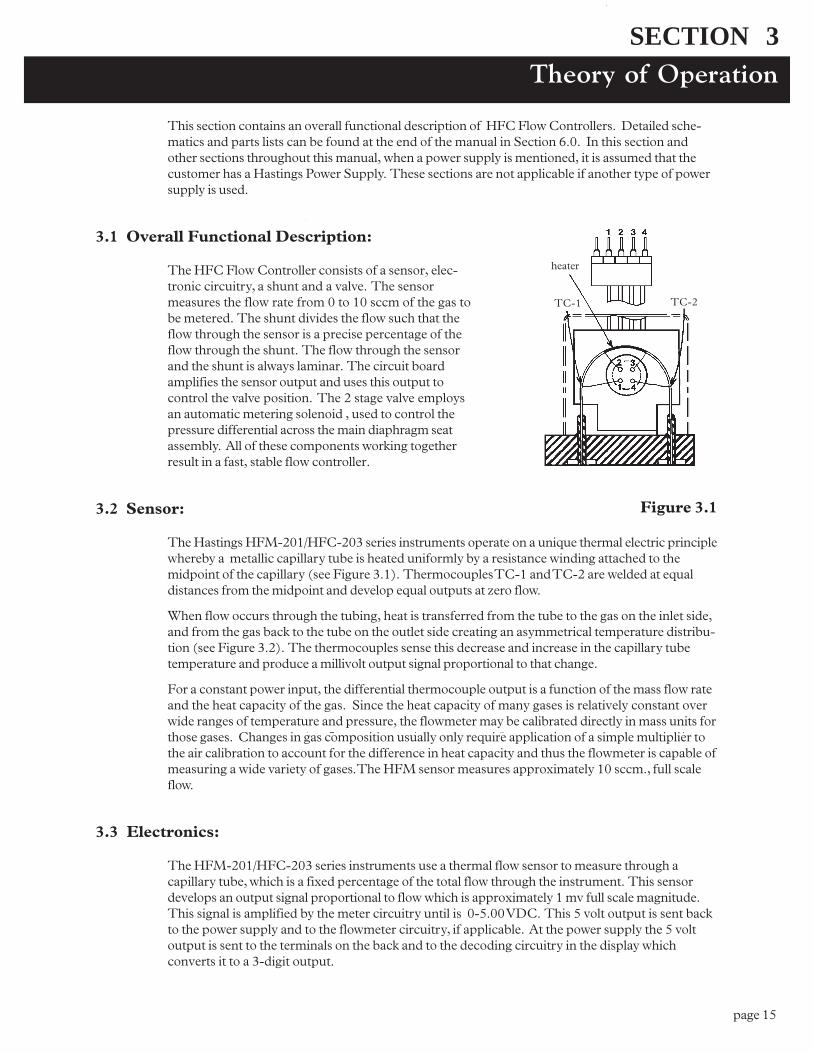
The HFC Flow Controller consists of a sensor, elec-tronic circuitry, a shunt and a valve. The sensormeasures the flow rate from 0 to 10 sccm of the gas tobe metered. The shunt divides the flow such that theflow through the sensor is a precise percentage of theflow through the shunt. The flow through the sensorand the shunt is always laminar. The circuit boardamplifies the sensor output and uses this output tocontrol the valve position. The 2 stage valve employsan automatic metering solenoid , used to control thepressure differential across the main diaphragm seatassembly. All of these components working togetherresult in a fast, stable flow controller.
3.2 Sensor:
The Hastings HFM-201/HFC-203 series instruments operate on a unique thermal electric principlewhereby a metallic capillary tube is heated uniformly by a resistance winding attached to themidpoint of the capillary (see Figure 3.1). Thermocouples TC-1 and TC-2 are welded at equaldistances from the midpoint and develop equal outputs at zero flow.
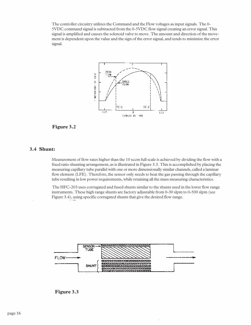
When flow occurs through the tubing, heat is transferred from the tube to the gas on the inlet side,and from the gas back to the tube on the outlet side creating an asymmetrical temperature distribu-tion (see Figure 3.2). The thermocouples sense this decrease and increase in the capillary tubetemperature and produce a millivolt output signal proportional to that change.
For a constant power input, the differential thermocouple output is a function of the mass flow rateand the heat capacity of the gas. Since the heat capacity of many gases is relatively constant overwide ranges of temperature and pressure, the flowmeter may be calibrated directly in mass units forthose gases. Changes in gas composition usually only require application of a simple multiplier tothe air calibration to account for the difference in heat capacity and thus the flowmeter is capable ofmeasuring a wide variety of gases. The HFM sensor measures approximately 10 sccm., full scaleflow.
3.3 Electronics:
The HFM-201/HFC-203 series instruments use a thermal flow sensor to measure through acapillary tube, which is a fixed percentage of the total flow through the instrument. This sensordevelops an output signal proportional to flow which is approximately 1 mv full scale magnitude.This signal is amplified by the meter circuitry until is 0-5.00 VDC. This 5 volt output is sent backto the power supply and to the flowmeter circuitry, if applicable. At the power supply the 5 voltoutput is sent to the terminals on the back and to the decoding circuitry in the display whichconverts it to a 3-digit output.
heater
TC-1 TC-2
Figure 3.1
page 16
The controller circuitry utilizes the Command and the Flow voltages as input signals. The 0-5VDC command signal is subtracted from the 0-5VDC flow signal creating an error signal. Thissignal is amplified and causes the solenoid valve to move. The amount and direction of the move-ment is dependent upon the value and the sign of the error signal, and tends to minimize the errorsignal.
Figure 3.2
Figure 3.3
3.4 Shunt:
Measurement of flow rates higher than the 10 sccm full scale is achieved by dividing the flow with afixed ratio shunting arrangement, as is illustrated in Figure 3.3. This is accomplished by placing themeasuring capillary tube parallel with one or more dimensionally similar channels, called a laminarflow element (LFE). Therefore, the sensor only needs to heat the gas passing through the capillarytube resulting in low power requirements, while retaining all the mass measuring characteristics.
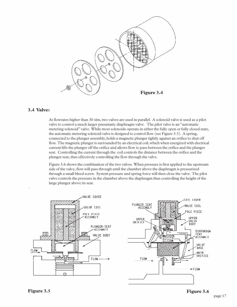
The HFC-203 uses corrugated and fused shunts similar to the shunts used in the lower flow rangeinstruments. These high range shunts are factory adjustable from 0-30 slpm to 0-500 slpm (seeFigure 3.4), using specific corrugated shunts that give the desired flow range.
page 17
3.4 Valve:
At flowrates higher than 30 slm, two valves are used in parallel. A solenoid valve is used as a pilotvalve to control a much larger pneumatic diaphragm valve. The pilot valve is an �automaticmetering solenoid� valve. While most solenoids operate in either the fully open or fully closed state,the automatic metering solenoid valve is designed to control flow (see Figure 3.5). A spring,connected to the plunger assembly, holds a magnetic plunger tightly against an orifice to shut offflow. The magnetic plunger is surrounded by an electrical coil, which when energized with electricalcurrent lifts the plunger off the orifice and allows flow to pass between the orifice and the plungerseat. Controlling the current through the coil controls the distance between the orifice and theplunger seat, thus effectively controlling the flow through the valve.
Figure 3.6 shows the combination of the two valves. When pressure is first applied to the upstreamside of the valve, flow will pass through until the chamber above the diaphragm is pressurizedthrough a small bleed screw. System pressure and spring force will then close the valve. The pilotvalve controls the pressure in the chamber above the diaphragm thus controlling the height of thelarge plunger above its seat.
Figure 3.4
Figure 3.5 Figure 3.6

page 18
page 19
Maintenance
SECTION 4
This section contains service and calibration information. Some portions of the instrument aredelicate. Use extreme care when servicing the flow controller. The potentiometer positions and theelectrical components referred to in the troubleshooting section can be found in Section 6.0 on theelectrical component layout drawing.
4.1 Authorized Maintenance
With proper care in installation and use, the flow controller will require little or no maintenance. Ifmaintenance does become necessary, most of the instrument can be cleaned or repaired in the field.Some procedures may require recalibration. Do not attempt these procedures unless facilities areavailable. Entry into the sensor or tampering with the printed circuit board will void warranty. Donot perform repairs on these assemblies while unit is still under warranty.
4.2 Troubleshooting
SYMPTSYMPTSYMPTSYMPTSYMPTOMOMOMOMOM: Output reads 40% of flow with no flow. Zero pot has no effect.
CACACACACAUSEUSEUSEUSEUSE: Power supply locked up or shorted out.
AAAAACTIONCTIONCTIONCTIONCTION: Turn off power supply for a few seconds, then turn back on. If this proves ineffective,disconnect the unit from the power supply. If power supply display does not return to zero, then aregulator chip in the power supply is probably burned out. Check supply voltages and replacefaulty regulator. If display returns to zero after disconnecting the power supply from the unit thereis a short in the unit to ground. Check capacitors C10 & C11 first.
SYMPTSYMPTSYMPTSYMPTSYMPTOMOMOMOMOM: Override switch is in CLOSE position, but flow remains or 0.00 VDC is com-manded and flow remains.
CAUSECAUSECAUSECAUSECAUSE: Orifice out of adjustment or faulty op-amp
AAAAACTIONCTIONCTIONCTIONCTION: Check valve voltage at connector pins TP-3 & TP-6. If voltage is less than 3.00 VDC,then turn orifice clockwise until flow stops. If voltage is greater than 3.00 VDC. If they aregreater, replace U1; if less, replace transistor Q1.
SYMPTOMSYMPTOMSYMPTOMSYMPTOMSYMPTOM: Output of unit is proportional to flow but extremely small and not correctable byspan pot.
CAUSECAUSECAUSECAUSECAUSE: Sensor is not being heated.
AAAAACTIONCTIONCTIONCTIONCTION: Unplug connector J2. Check the following resistance: The resistance between pins 2& 3 of the sensor should be approximately 2500 ohms (see Figure 3.1 on page 8). The resistancebetween pins 1 & 4 should be approximately 2.3 ohms. The resistance between pins 2 & 3 and thebase of the sensor should be essentially infinite. If not, replace the sensor unit. If sensor readsO.K., check the voltage output on pins 2 & 3 of the jack in the board. If it does not read approxi-mately 22 VDC then replace op-amp U2.
SYMPTSYMPTSYMPTSYMPTSYMPTOMOMOMOMOM: Sensor has proper resistance readings, but little or no output with flow.
CAUSECAUSECAUSECAUSECAUSE: Plugged sensor.
AAAAACTIONCTIONCTIONCTIONCTION: Shut off gas supply and power supply. Remove cover and PC board from unit.Remove sensor assembly and examine. If sensor has evidence of plugging, clean or replace asapplicable
page 20
SYMPTOMSYMPTOMSYMPTOMSYMPTOMSYMPTOM: Flow controller oscillates.
CAUSECAUSECAUSECAUSECAUSE: Flow controller not adjusted for the dynamics of the flow system.
AAAAACTIONCTIONCTIONCTIONCTION: Check upstream and downstream pressures. The gas supply regulator should not haveexcessive lockup when flow shuts off. Also ensure that there is not a large drop in pressure betweenthe regulator and the instrument due to line resistance. Oscillations can also be caused if a largeflow restriction is pneumatically close to the downstream end of the flow controller. The differentialpressure across the unit must be between 10-50 psig.
SYMPTSYMPTSYMPTSYMPTSYMPTOMOMOMOMOM: Little or no flow, even with Valve Override switch OPEN.
CAUSECAUSECAUSECAUSECAUSE: Plugged orifice.
AAAAACTIONCTIONCTIONCTIONCTION: Verify the presence of a 10-50 psig pressure across the instrument. If present, shut offgas supply and power supply. Remove orifice per Section 4.9. Examine orifice. If plugged, cleanor replace as applicable. Reassemble valve.
SYMPTSYMPTSYMPTSYMPTSYMPTOMOMOMOMOM: Flowmeter reads other than 0.00 VDC with no flow, or there is a small flow whenflowmeter reads 0.00 VDC.
CACACACACAUSEUSEUSEUSEUSE: ZERO potentiometer is out of adjustment.
AAAAACTIONCTIONCTIONCTIONCTION: Shut off all flow. Adjust ZERO potentiometer until output reads 0.00 VDC.
SYMPTOMSYMPTOMSYMPTOMSYMPTOMSYMPTOM: Flowmeter out of calibration and nonlinear.
CAUSECAUSECAUSECAUSECAUSE: Leaks in gas inlet or outlet fittings.
AAAAACTIONCTIONCTIONCTIONCTION: Check all fittings for leaks by placing soap solution on all fittings between gas supplyand final destination of gas. Check flowmeter for leaks. Replace �O� rings if required or recalibrateas necessary.
4.3 ADJUSTMENTS
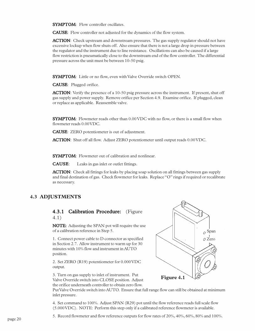
4.3.1 Calibration Procedure:4.3.1 Calibration Procedure:4.3.1 Calibration Procedure:4.3.1 Calibration Procedure:4.3.1 Calibration Procedure: (Figure4.1)
NONONONONOTE:TE:TE:TE:TE: Adjusting the SPAN pot will require the useof a calibration reference in Step 5.
1. Connect power cable to D connector as specifiedin Section 2.7. Allow instrument to warm up for 30minutes with 10% flow and instrument in AUTOposition.
2. Set ZERO (R19) potentiometer for 0.000 VDCoutput.
3. Turn on gas supply to inlet of instrument. PutValve Override switch into CLOSE position. Adjustthe orifice underneath controller to obtain zero flow.Put Valve Override switch into AUTO. Ensure that full range flow can still be obtained at minimuminlet pressure.
4. Set command to 100%. Adjust SPAN (R29) pot until the flow reference reads full scale flow(5.000 VDC). NOTE: Perform this step only if a calibrated reference flowmeter is available.
5. Record flowmeter and flow reference outputs for flow rates of 20%, 40%, 60%, 80% and 100%.
Figure 4.1
Span
Zero
page 21
4.3.2 Miscellaneous adjustments4.3.2 Miscellaneous adjustments4.3.2 Miscellaneous adjustments4.3.2 Miscellaneous adjustments4.3.2 Miscellaneous adjustments
Periodically, during normal operation, the ZERO should be checked and adjusted when required. Ifsystem parameters change, the RESPONSE pot may require a small adjustment for optimumstability. If the instrument is not shutting completely off when Valve Override switch is in theCLOSE position, the orifice may require approximately 1/8 turn clockwise.
4.4 End Cap Removal:
The end cap on the inlet side must be removed to gain access to the filter or shunt assembly. Firstshut off the supply of gas to the instrument. Disconnect the Swagelok fitting on the inlet and outletsides of the transducer, and remove it from the system plumbing. Remove the four hex boltsholding the end cap to the instrument (see Figure 4.1). Carefully remove the end cap, filter, wavespring (if present) and shunt, noting their order and proper orientation. The shunt can be severelydamaged if dropped. Examine the filter and shunt. If either is dirty or blocked, clean or replace asapplicable. Reassembly is the reverse of the removal procedure. Recalibration of the HFC isRecalibration of the HFC isRecalibration of the HFC isRecalibration of the HFC isRecalibration of the HFC isnecessarnecessarnecessarnecessarnecessar yyyyy.....
4.5 Printed Circuit Board Replacement
In the unlikely event that the PC board fails, it is easily removed from the instrument and replacedwith a spare to minimize instrument downtime. Replacement of the PC board will require theinstrument to be recalibrated per Section 4.4.1.
Unplug the power cable from the top of the transducer. Remove the two jackscrews next to the�D� connector and the two screws on the sides of the cover. Lift off the cover and unplug thefour-wire sensor plug and the two wire valve plug, noting their orientation prior to removal.
Remove the screw that holds the PC board to the sensor. Troubleshoot or replace as applicable.Installation is the reverse of the above procedure. Recalibrate if any components were changed orif any potentiometers were adjusted.
4.6 Sensor Replacement:
If the sensor fails or becomes plugged it can be removed. Remove the cover and the PC board perSection 4.7 above. Remove the three bolts holding the sensor to the instrument base. Remove thesensor from the base noting the two O-rings (Parker 2-005, V884-75) between the sensor and thebase. If the sensor is plugged it can be cleaned by running a fine wire (approximately 0.008"diameter) through the tube. If sensor needs replacement, obtain another from the factory andinstall it. Ensure that O-rings are clean and intact. Install O-rings on seating surface, then carefullyplace sensor over O-rings and tighten down the three screws evenly. Replacement of sensor willrequire recalibration per Section 4.3.1.
4.7 Orifice Changes:
The orifice may require replacement if a flow range change is desired, if a large change in differen-tial pressures across the valve is desired or in the event that a small orifice becomes plugged.Replacement orifices can be acquired from the factory. See Section 4.8 for the list of standardorifices and their flow rates in air.
When using nonstandard pressures or gases that have specific gravities different than air (such ashydrogen or helium), the diameter of the orifice must be calculated using the following procedure:
page 22
A) Determine the minimum expected upstream pressure (Pu) in PSI absolute and the maximumexpected downstream pressure (Pd) in PSI absolute for full flow conditions.
B) If Pu >2Pd, use formula 1; otherwise use formula 2.
Where:
D = Diameter in inches
Q = Flowrate in standard liters per minute
P = Pu - Pd in PSI
Pu = Upstream pressure in PSIA
Pd = Downstream pressure in PSIA
s = Specific gravity of gas
Choose the orifice form Section 5.0 that has the closes larger diameter to the calculated diameter.
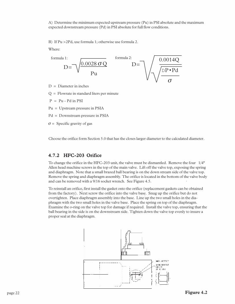
4.7.2 HFC-203 Orifice4.7.2 HFC-203 Orifice4.7.2 HFC-203 Orifice4.7.2 HFC-203 Orifice4.7.2 HFC-203 Orifice
To change the orifice in the HFC-203 unit, the valve must be dismantled. Remove the four 1/4"Allen head machine screws in the top of the main valve. Lift off the valve top, exposing the springand diaphragm. Note that a small brazed ball bearing is on the down stream side of the valve top.Remove the spring and diaphragm assembly. The orifice is located in the bottom of the valve bodyand can be removed with a 9/16 socket wrench. See Figure 4.5.
To reinstall an orifice, first install the gasket onto the orifice (replacement gaskets can be obtainedfrom the factory). Next screw the orifice into the valve base. Snug up the orifice but do notovertighten. Place diaphragm assembly into the base. Line up the two small holes in the dia-phragm with the two small holes in the valve base. Place the spring on top of the diaphragm.Examine the o-ring on the valve top for damage if required. Install the valve top, ensuring that theball bearing in the side is on the downstream side. Tighten down the valve top evenly to insure aproper seal at the diaphragm.
D=0.0028 s Q
Pu
D=0.0014Q
DP Pd
s
formula 1: formula 2:
Figure 4.2
page 23
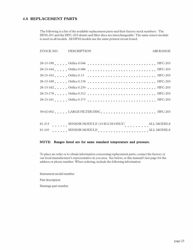
4.8 REPLACEMENT PARTS
The following is a list of the available replacement parts and their factory stock numbers. TheHFM-201 and the HFC-203 shunts and filter discs are interchangeable. The same sensor moduleis used on all models. All HFM models use the same printed circuit board.
STOCK NO. DESCRIPTION AIR RANGE
28-13-190 Orifice 0.046 HFC-203
28-13-164 Orifice 0.086 HFC-203
28-13-163 Orifice 0.13 HFC-203
28-13-189 Orifice 0.156 HFC-203
28-13-162 Orifice 0.250 HFC-203
28-13-178 Orifice 0.312 HFC-203
28-13-161 Orifice 0.375 HFC-203
39-02-002 LARGE FILTER DISC HFC-203
81-213 SENSOR MODULE (10 SCCM ONLY) ALL MODELS
81-105 SENSOR MODULE ALL MODELS
NOTE: Ranges listed are for same standard temperature and pressure.NOTE: Ranges listed are for same standard temperature and pressure.NOTE: Ranges listed are for same standard temperature and pressure.NOTE: Ranges listed are for same standard temperature and pressure.NOTE: Ranges listed are for same standard temperature and pressure.
To place an order or to obtain information concerning replacement parts, contact the factory orour local manufacturer�s representative in you area. See below, or this manual�s last page for theaddress or phone number. When ordering, include the following information:
Instrument model number
Part description
Hastings part number
○ ○ ○ ○ ○
○ ○ ○ ○ ○
○ ○ ○ ○ ○
○ ○ ○ ○ ○
○ ○ ○ ○ ○
○ ○ ○ ○ ○
○ ○ ○ ○ ○
○ ○ ○ ○ ○
○ ○ ○ ○ ○ ○ ○ ○ ○ ○ ○ ○ ○ ○ ○ ○ ○ ○ ○ ○ ○ ○ ○ ○ ○ ○ ○
○ ○ ○ ○ ○ ○ ○ ○ ○ ○ ○ ○ ○ ○ ○ ○ ○ ○ ○ ○ ○ ○ ○ ○ ○ ○ ○
○ ○ ○ ○ ○ ○ ○ ○ ○ ○ ○ ○ ○ ○ ○ ○ ○ ○ ○ ○ ○ ○ ○ ○ ○ ○ ○
○ ○ ○ ○ ○ ○ ○ ○ ○ ○ ○ ○ ○ ○ ○ ○ ○ ○ ○ ○ ○ ○ ○ ○ ○ ○ ○
○ ○ ○ ○ ○ ○ ○ ○ ○ ○ ○ ○ ○ ○ ○ ○ ○ ○ ○ ○ ○ ○ ○ ○ ○ ○ ○
○ ○ ○ ○ ○ ○ ○ ○ ○ ○ ○ ○ ○ ○ ○ ○ ○ ○ ○ ○ ○ ○ ○ ○ ○ ○ ○
○ ○ ○ ○ ○ ○ ○ ○ ○ ○ ○ ○ ○ ○ ○ ○ ○ ○ ○ ○ ○ ○ ○ ○ ○ ○ ○
○ ○ ○ ○ ○ ○ ○ ○ ○ ○ ○ ○ ○ ○ ○ ○ ○ ○ ○ ○ ○ ○
○ ○ ○ ○ ○ ○
○ ○ ○ ○ ○ ○ ○ ○ ○ ○ ○ ○ ○ ○ ○ ○ ○ ○ ○ ○ ○ ○ ○ ○ ○ ○
○ ○ ○ ○ ○ ○ ○ ○ ○

page 24
page 25
Warranty and Repair
SECTION 5
5.1 Warranty Policy
Hastings Instruments warrants this product, for a period of one year from the date of shipment, tobe free from defects in material and workmanship. This warranty does not apply to defects orfailures resulting from unauthorized modification, misuse or mishandling of the product. Thiswarranty does not apply to batteries or other expendable parts, nor to damage caused by leakingbatteries or any similar occurrence. This warranty does not apply to any instrument which has hada tamper seal removed or broken.
This warranty is in lieu of all other warranties, expressed or implied, including any implied warrantyas to fitness for a particular use. Hastings Instruments shall not be liable for any indirect or conse-quential damages.
Hastings Instruments will, at its option, repair, replace, or refund the selling price of the product ifHastings Instruments determines in good faith, that it is defective in materials or workmanshipduring the warranty period. Defective instruments should be returned to Hastings Instrumentstogether with a written statement of the problem and a Return Material Authorization (RMA)number. Please consult the factory for your RMA number before returning any product for repair.
5.2 Non-Warranty Repair Policy
Any product returned for a non-warranty repair must be accompanied by a purchase order, RMAform and a written description of the problem with the instrument. If the repair cost is higher, youwill be contacted for authorization before we proceed with any repairs. If you then choose not tohave the product repaired, a minimum will be charged to cover the processing and inspection.Please consult the factory for your RMA number before returning any product for repair.
TET-HASTINGS INSTRUMENTS
804 NEWCOMBE AVENUE
HAMPTON, VIRGINIA 23669 U.S.A.
ATTENTION: REPAIR DEPARTMENT
TELEPHONE (757) 723-6531
1-800-950-2468
FAX (757) 723-3925

page 26
page 27
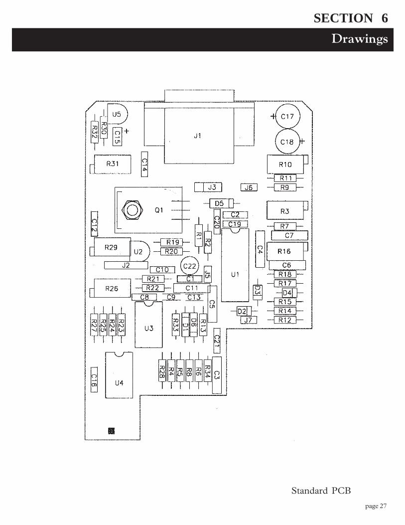
Drawings
SECTION 6
Standard PCB
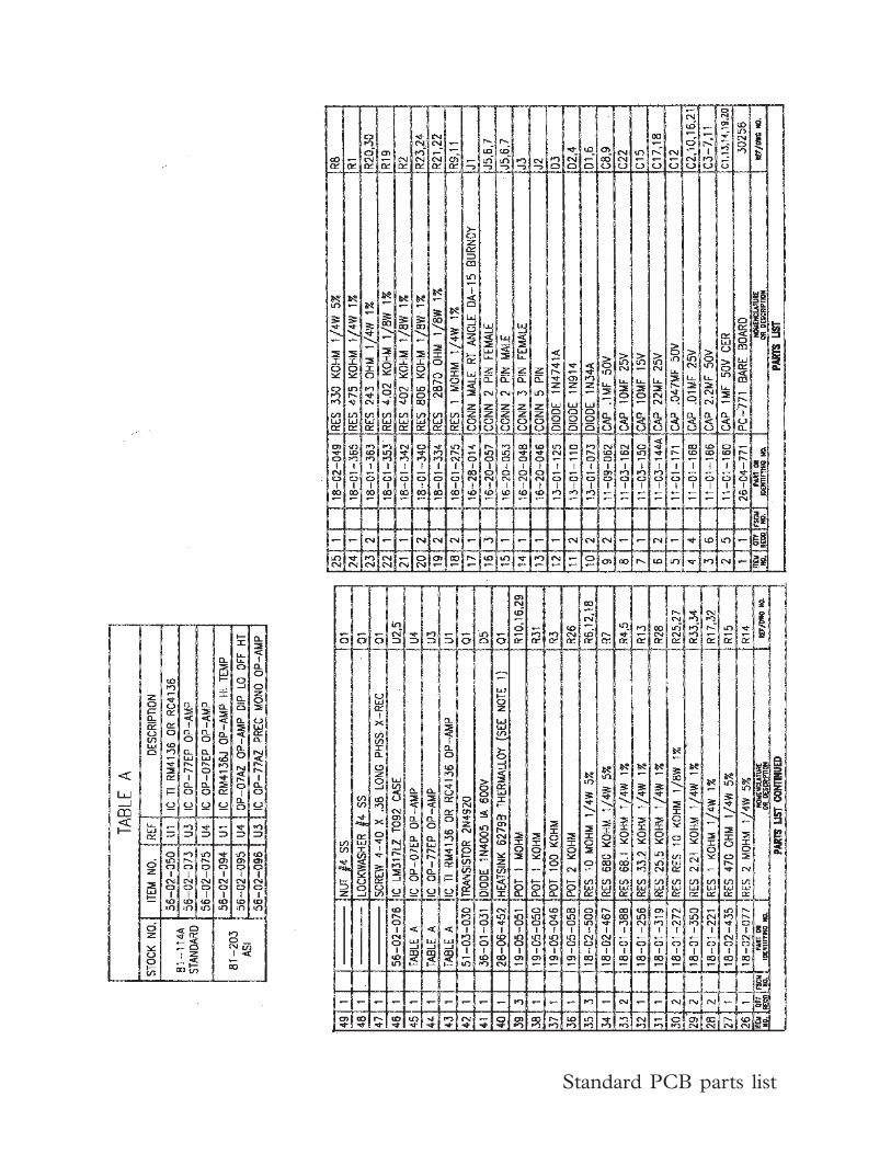
page 28
Standard PCB parts list
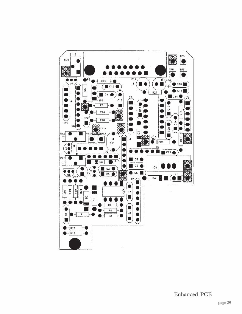
page 29
Enhanced PCB
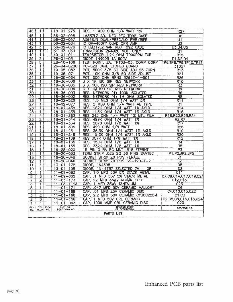
page 30
Enhanced PCB parts list
page 31
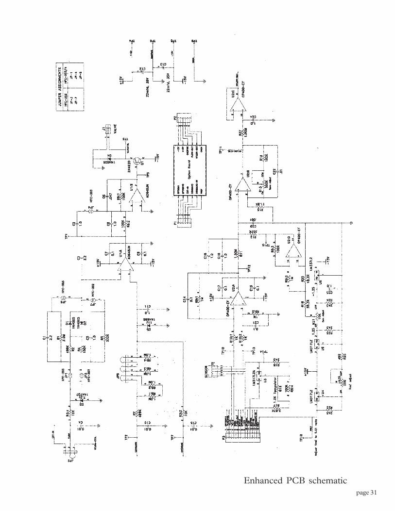
Enhanced PCB schematic
page 32
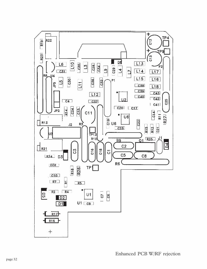
Enhanced PCB W/RF rejection
page 33
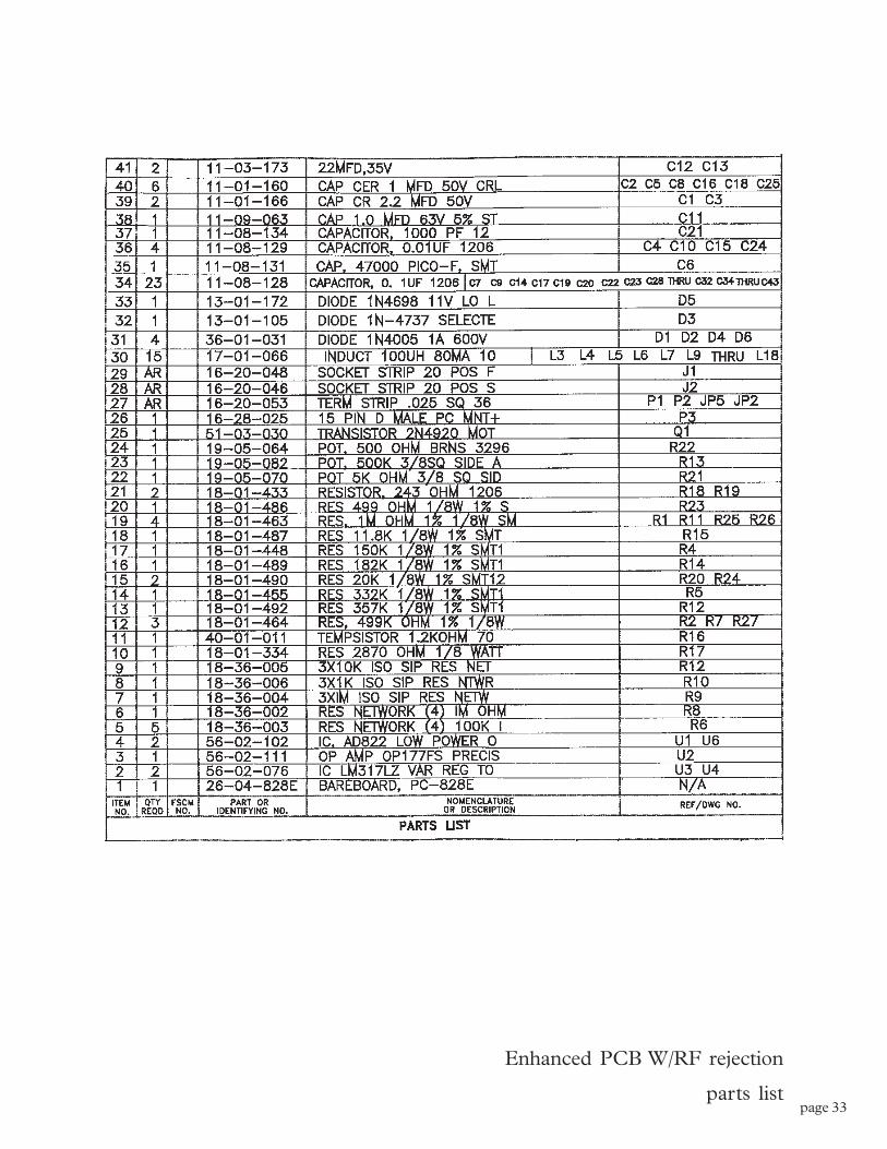
Enhanced PCB W/RF rejection
parts list
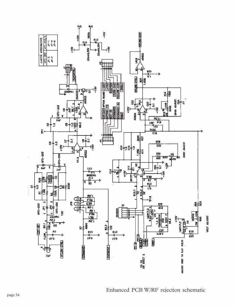
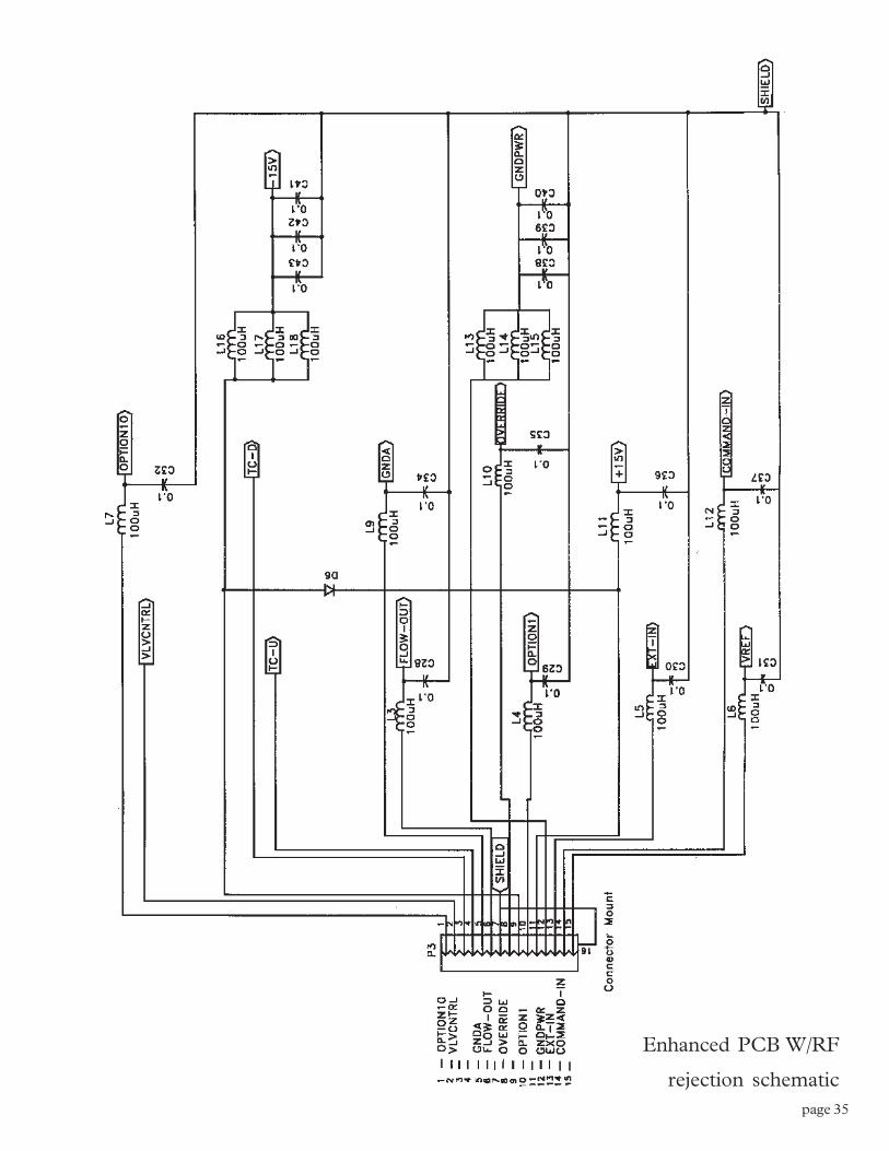
page 34Enhanced PCB W/RF rejection schematic
page 35
Enhanced PCB W/RF
rejection schematic

page 36