Embed Size (px)
Citation preview
16 PARKINSON
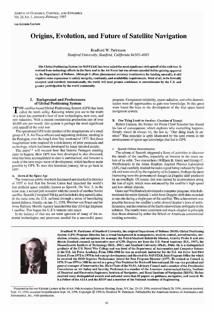
Fig 6 System con guration of GPS showing the three fundamental segments (Drawing courtesy of US Air Force)
becomes the Y (or PY) code (There are provisions in the FederalRadio-Navigation Plan for users with critical national needs to gainaccess to the P code)
a) Selective availability The military operators of the systemhave the capability to intentionally degrade the accuracy of the CAsignal by desynchronizing the satellite clock or by incorporatingsmall errors into the broadcast ephemeris This degradation is calledselective availability (SA) The magnitude of these ranging errors istypically 20 m and results in rms horizontal position errors of about50 m (one-sigma) The of cial DOD position is that SPS errorswill be limited to 100 m (two-dimensional rms) which is about the97th percentile A technique known as differential GPS (DGPS) canovercome this limitation and potentially provide civilian receiverswith accuracies suf cient for precision landing of aircraft
b) Data modulation One additional feature of the ranging sig-nal is a 50-bps modulation which is used as a communicationslink Through this link each satellite transmits its location and thecorrection that should be applied to the spaceborne clock as well asother information (Although the atomic clocks are extremely sta-ble they are running in an uncorrected mode The clock correctionis an adjustment that synchronizes all clocks to GPS time)
3 Satellite Segmenta) Satellite orbital con guration The orbital con guration ap-
proved at DSARC in 1973 was a total of 24 satellites 8 in eachof three circular rings with inclinations of 63 deg (see Fig 7) Therings were equally spaced around the equator and the orbital alti-tudes were 10980 n mile This altitude gave two orbital periods persidereal day (known as semisynchronous) and produced repeatingground traces with satellites positioned 4 min earlier each day Thealtitude was a compromise among user visibility the need to peri-odically pass over the Continental US groundupload stations andthe cost of the US Air Force spacecraft launch boosters
Three rings of satellites were initially selected because it wouldbe easier to have orbital spares having only three such spares (onein each ring) would allow easy replacement of any single failure inthe whole constellation This con guration provided a minimum of6 satellites in view at any given time with a maximum of 11 As a
Fig 7 Original GPS orbital con guration of three rings of eight satel-lites each The nal operational con guration has the same number ofsatellites arranged in six rings of four satellites (Drawing courtesy ofUS Air Force)
result of this redundancy the system was robust in the sense that itcould tolerate occasional satellite outages
Two changes have since been made to the original constellationproposal The inclinations have been reduced to55 deg and the num-ber of orbital planes have been increased to six with four satellitesin each The number of satellites including spares remains 24 Thisconstellation still gives six or more satellites in view all the timevirtually everywhere in the world This assumes that there are no out-ages and all satellites more than 5 deg above the horizon can be seen
PARKINSON 17
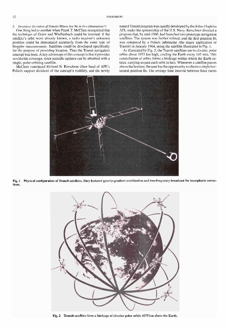
Fig 8 Breakaway view of the GPS phase one satellite design Satellite characteristics weight at booster-satellite separation = 1636 lb weight atinsertion into nal orbit = 982 lb antenna span = 175 ft design life = 5 years and life of consumables = 7 years (Drawing courtesy of US Air Force)
Fig 9 Space-quali ed rubidium-cell frequency-standard performance These units were developed by Rockwell as a derivative of a clock designedby Efratom Inc under contract to the NRL (Data courtesy of US Air Force)
In the US typical coverage is 6ndash8 or more in view The minimumnumber of 4 satellites (to navigate) is therefore reasonably assured
Many users would like to have 6 or more to perform cross checkson the integrity of the positioning solution To attain this at all timesis obviously more dif cult This so-called availability problem willbe addressed later
b) Satellite design All GPS satellites are attitude stabilized on allthree axes and use solar panels as the primary power source Theranging signal is radiated through a shaped beam antenna by en-hancing the received power at the limbs of the Earth compensationis made for space losses The user therefore receives fairly constantpower for all local elevation angles (The requirement for receivedpower on L1 is iexcl163 dBW into an isotropic circularly polarizedantenna on the primary frequency) The satellite design is gener-ally doubly or triply redundant and the phase one satellites havedemonstrated average lifetimes in excess of 5 years (and in somecases over 12) This satellite design is shown in Fig 8
c) Satellite autonomy atomic clocks A key feature of the GPSdesign is that the satellites need not be continuously monitoredand controlled To achieve this autonomy the satellites must be
predictable in four dimensions three of position and one of timePredictability in orbital position is improved because the high-altitude orbits are virtually unaffected by atmospheric drag Manyother factors that affect orbital position must also be considered Forexample lunarndashsolar perturbations solar pressure and outgassingcan all have signi cant effects
When GPS was conceived it was recognized that the most dif- cult technology problem facing the developers was probably theneed to y accurate long-lived timing standards to ensure that allof the satellitesrsquo clocks remained synchronized As mentioned theTIMATION program had been developing frequency standards forspace and so this effort was continued and extended
GPS has traditionally used two types of atomic clocks rubidiumand cesium Phase one test results for the rubidium cell standard areshown later A key to outstanding satellite performance has been thestability of the space-quali ed atomic clocks which have exceededtheir speci cations They have measured stabilities of one part in1013 over periods of 1ndash10 days9 Test results are shown in Fig 9
d) Ionospheric errors and corrections Free electrons in the iono-sphere create a delay in the modulation signal (PRN code) It is
18 PARKINSON
not unusual to nd delays of over 30 m at lower satellite elevationangles There are two techniques for correcting this error The rstis to use an ionosphere model The model parameters are broadcastas part of the GPS 50-bps message This model is typically accurateto a few meters of vertical ranging error
The second technique uses both broadcast frequencies and theinverse square law behavior to directly measure the delay By dif-ferencing the code measurements on each frequency the delay onL1 is approximately 1546 (difference in delays on L1 and L2)(The delay at 1575 MHz is found as the difference in delay mul-tiplied by [ f 2
2 = f 21 iexcl f 2
2 ] because it is proportional to the inversefrequency squared The frequency of L2 is 1227 MHz) This tech-nique is only available to a PY code receiver (since only the P codehas L2 modulation) or to a codeless (or cross-correlating) receiver
III Incubation and Birth GPS from 1973 to 1978A Approval to Proceed with GPS
To gain approval for the new concept Parkinson began to contactall those with some stake in the decision After interminable roundsof brie ngs16 on the new approach were given to of ces in the Pen-tagon and to the operating armed forces a successful DSARC washeld on Dec 17 1973 only three months after GPS was conceived[Gen Kenneth Schultz was particularly incensed with the endlesspresentations thathad to be made in the Washington arena The situa-tion with any bureaucracy is that many can say no and few (if any)cansay yes To bring the nay sayers to neutral extended trips from LosAngeles to Washington were necessary for Parkinson] Approval toproceed was granted in a memorandum dated Dec 22 1973
B Fast Start to DevelopmentThe rst phase of the program originally included four satellites
(one was the refurbished quali cation model) the launch vehiclesthree varieties of user equipment a satellite control facility and anextensive test program
By June of 1974 the satellite contractor Rockwell Internationalhad been selected and the program was well underway Magnavoxwhich had been a key participant in the user equipment for 621B(along with Hazeltine) was selected to develop the user equipmentunder subcontract to General Dynamics which was also responsiblefor developing the satellite control segment and the pseudosatellitesfor the Yuma range
The initial types of user equipment included sequential (the Yset) and parallel (the X set) satellite-tracking military receivers aswell as a civilian-type set for utility use by the military (the Z set)
Fig 10 Phase one GPS satellite is a three-axis stabilized design with double and triple redundancy where appropriate (Drawing courtesy of US AirForce)
The development test and evaluation was extensive with a lasertracking range set up at the Armyrsquos Yuma Proving Ground Anindependent evaluation was then performed by the Air Forcersquos Testand Evaluation Command
To maintain the focus of the program the GPS JPO adopted thefollowing simple and direct motto
The mission of this program is to1) drop 5 bombs in the same hole and2) build a cheap set that navigates (lt$10000)
and donrsquot you forget itThe $10000 price goal was considered very ambitiousThe program developed rapidly the rst prototype operational
satellite was launched in February 1978 (44 months after contractstart) The design is shown in Fig 10 By this time the initial controlsegment was deployed and working and ve types of user equip-ment were undergoing preliminary testing at the Yuma ProvingGround The initial user equipment types had been expanded toinclude a ve-channel set developed by Texas Instruments and ahighly jam-resistant set developed by Rockwell Collins
C Further Technology DevelopmentThe NAVSTAR GPS Development Concept Paper 133 approved
in 1973 called for NRL to continue the technology efforts begunin the TIMATION project under JPO direction A cesium-standardsatellite clock was selected as the most promising candidate formeeting the ultimate requirements of the program The NRL pro-gram was to aid in demonstrating the feasibility of the system con-cept by constructing NTS and to advance the state of the art innavigation satellite technology
The second technology satellite built by NRL NTS-II was the rst satellite launched in the NAVSTAR GPS program that wasspeci cally built to the GPS concept Shown being placed atop theAtlas F launch system at Vandenberg in Fig 11 it was launched inJune 1977 NTS-II contained the rst two prototype cesium-beamfrequency standards to be own in space An essential componentwas the navigation payload which was provided by the JPO
While NTS-II was short lived the performance of the NTS-IIunits was a frequency stability of 2 parts in 10iexcl13 per day giving atime error of about 20 ns a day
D Needed A Few More Good SatellitesBecause only four satellites were initially approved by the
DOD including a refurbished quali cation model there was aneed for spare satellites (Recall that the minimum number for
PARKINSON 19
Fig 11 NTS-II being placed on an Atlas-F booster at Vandenberg AirForce Base
three-dimensional navigation is four) Any launch or operationalfailure would have gravely impacted the phase one demonstrationprogram Authorization for additional GPS satellites was urgentlyneeded
The Navyrsquos Transit program inadvertently solved this problemThis chain of events unfolded when Transit requested funds forupgrading certain Transit satellites to a PRN code similar to that usedby GPS The purpose was to provide accurate tracking of the Trident(submarine-launched ballistic missile) booster during test ringsinto the broad ocean areas Robert Cooper of DDRampE requested aseries of reviews to address whether GPS could ful ll this mission
The GPS solution was to use a signal translator on the Trident mis-sile bus which would relay the GPS modulations to the ground onanother frequency The central issues were whether the ionospherecould be adequately calibrated (because it was a single-frequencysystem the ionosphere could not be directly measured) and whetherthe translated signal could be recorded with suf cient delity (it re-quired digitizing at 60 MHz)
During the third (and capstone) review for Cooper Parkinson(supported by James Spilker and John Klobuchar) was able topresent convincing arguments that a GPS solution could solve theTrident problem provided two additional satellites were authorizedCooper immediately made the decision to use GPS He directed thetransfer of $60 million from the Navy to the Air Force This approvedtwo additional satellites and thereby greatly expanded the phase onetest time as well as signi cantly reduced program risk This little-known event also eliminated the possibility of an upgraded Transitprogram competing with the edgling GPS
E Why Is It Called NAVSTAR or GPSThere has been much speculation regarding the origin of the
names GPS and NAVSTAR The GPS title originated with GenldquoHankrdquo Stehling who was the Director of Space for the Air ForceDeputy Chief of Staff research and development in the early 1970sHe pointed out to Parkinson that navigation was an inadequate de-scriptor for the proposed concept He suggested that Global Posi-tioning System or GPS would be a better name The JPO enjoyedhis sponsorship and this insightful description was immediatelyadopted
The title NAVSTAR came into being in a somewhat similar man-ner John Walsh (an Associate Director of DDRampE) was a key de-cision maker when it came to the budget for strategic programs ingeneral including the proposed satellite navigation program In thecontention for funding his support was not as fervent as the JPOwould have liked During a break in informal discussions betweenJohn Walsh and Col Brent Brentnall (the programrsquos representativeat DOD) Walsh suggested that NAVSTAR would be a nice sounding
name Brentnall passed this along as a good idea to Parkinson not-ing that if Walsh were to name it he would undoubtedly feel moreprotective toward it Parkinson seized this opportunity and sincethat time the program has been known as NAVSTAR the GlobalPositioning System While some have assumed that NAVSTAR wasan acronym in fact it was simply a pleasant name that enjoyed thesupport of a key DOD decision maker [It is noted that TRW ap-parently had advocated a navigational system for which NAVSTARwas an acronym (Navigation system timing and ranging) This mayhave been in Walshrsquos subliminal memory but was not part of theprocess It was never used as an acronym]
IV Coming of Age GPS from 1978 to the PresentIn the early years the GPS program enjoyed only lukewarm sup-
port from the US Air Force because it was viewed as a DODprogram As a result many attempts were made to cancel its de-velopment This led to key actions to broaden its usefulness andhence its support Initially it was felt that the full system could bemade operational by 1984 Principally due to funding restrictionsand redirection the system was not able to become operational until1994 Had the phase one satellites simply gone into production thiscould have occurred almost 10 years earlier
A Add Ons and Delays the Perils of InnovationTo expand political support additional operational payloads were
incorporated into the baseline design From its vantage point inspace the NAVSTAR satellites potentially could time nuclear ex-plosions on the ground from many directions and pinpoint theirlocations This capability was added along with various others
These innovations were essential for continuing support but alsocontributed to delays in the program because they required exten-sive modi cations to the satellites Steady progress has been madein GPS satellite development but the real revolution has been thediminishing cost and increased capabilities of GPS user equipment
B SATo protect the US against hostile use of GPS by enemies the
civilian signal is deliberately degraded in accuracy as describedearlier The name given this degradation is SA This action hasbeen a source of international tension over the potential adaptationof GPS as an of cial navigation standard Because these effects canbe calibrated out by a receiver at a known location on the ground(see later discussions of DGPS) the effectiveness of this techniqueto deny accuracy has come under severe questioning
V Status of GPS Performance and Test ResultsGPS offers two standard services in terms of accuracy As men-
tioned previously the service for military users is known as the PPSand is not affected by the deliberate degradation of SA The civilianservice is known as the SPS Both of these standard applications relyon the tracking of the modulation (or code) with no ground-basedcorrections More sophisticated techniques apply range correctionscomputed from ground receivers located at known positions Theseso-called differential techniques can attain relative accuracies ofbetter than a centimeter The following sections brie y summarizethe current situation
A Standard GPS Navigation PerformanceThe performance capabilities of standard GPS are primarily af-
fected by two things satellite geometry (which causes geometric di-lution) and ranging errors Under the assumption of uniform uncor-related zero-mean ranging error statistics this can be expressed as
position error D geometric dilution curren ranging error
1 Satellite Geometry Geometric Dilution EffectGeometric dilution can be calculated for any instantaneous satel-
lite con guration as seen from a user at a particular location For a24-satellite constellation and a three-dimensional x the world me-dian value of the geometric dilution factor (for the nominal constel-lation) is about 25 This quantity is usually called position dilutionof precision (PDOP) Typical dilution factors can range from 15 to8 The variations in this dilution factor are typically much greaterthan the variations in ranging errors
20 PARKINSON
2 Ranging ErrorsRanging errors are generally grouped into six major causes 1)
satellite ephemeris 2) satellite clock 3) ionospheric group delay4) tropospheric delay 5) multipath and 6) receiver measurementsWith SA turned off all errors for single-frequency SPS are nearlyidentical in magnitude to those for single-frequency PPS except forreceiver measurement errors (which decrease with increasing band-width) Dual frequency which is only available on PPS can reducethe third error (due to the ionosphere) to about 1 m This is summa-rized in Table 1 (Multipath errors are generally negligible for pathdelays that exceed one and one-half modulation chips expressed asa range Thus P code receivers reject re ected signals whose pathdelay exceeds 150 ft For the CA signal the number is 1500 ft giv-ing a slight advantage to the P code However it is usually re ectionsfrom very close objects that are the main sources of dif culty)
3 Expected Positioning Accuracies for PPS and SPSThe product of the rms PDOP and the ranging error for a single
satellite gives the three-dimensional rms position error Because thevalue of rms PDOP averages 25ndash30 (depending on user locationand the assumptions on minimum visible satellite elevation angleor mask angle) one can multiply 25 times the values in Table 1 to nd typical positioning errors Note that PDOP is the same for allusers civilian and military
A second way to specify accuracy is by spherical error probable(SEP) The SEP is de ned to be the radius of the sphere that contains50 of the errors For horizontal errors only similar concepts ofcircular error probable (CEP) and horizontal rms error can be usedto specify accuracy Typically the horizontal rms error is about 12times the CEP
Without the degradation ofSASPS would provide solutions withabout 50 greater error than single-frequency PPS due to uncom-pensated ionospheric effects and somewhat greater receiver noise(due to the narrower band CA signal) It is reasonable to expect thatrms horizontal errors for SPS with SA off would be less than 15 m
4 Positioning Accuracy Summary for Code Tracking ReceiversTable 2 summarizes the expected positioning accuracies for GPS
It includes a conservative allowance for ionospheric errors
B High AccuracyCarrier Tracking ReceiversA special feature of GPS which initially was not generally un-
derstood is the ability to obtain an extremely precise ranging signalby reproducing and tracking the rf carrier wave (157542 MHz)Because this signal has a wavelength of 19 cm (75 in) trackingit to 1100th of a wavelength provides a precision of about 2 mmGenerally carrier tracking techniques can be used in two ways For
Table 1 Nominal ranging errorsfor various classes of service
Class Ranging accuracy mof service Single freq Dual freq
PPS 5 3SPS no SA 6 NASPS with SA 20 NA
Table 2 Expected positioning accuracies for various GPSoperating conditions
SPSa
PPS Est capabilitySpec Measured No With
value m (static) m SA m SA m
Ranging 6 23 6 20accuracy
CEP mdashmdash 46 12 40(Horiz)
SEP mdashmdash 83b 22 72three-dimensional
aSPS results are believed to be conservativebFor dynamic PPS users reported to be less than 10 m
normal use carrier tracking can smooth code tracking and greatlyreduce the noise content of code ranging measurements
The other use of carrier tracking is in a differential modeThere areseveral variations of this including surveying direct measurementof vehicle attitude (with multiple antennas) and various forms ofdynamic differential Modern receivers can attain 2-mm trackingprecisions for this second use but unfortunately this is not accuracyRe ected signals (multipath) and distortions of the ionosphere canbe signi cant errors (ie on the order of a few centimeters) Inaddition to provide centimeter accuracy one must determine whichcarrier cycle is being tracked (relative to the start of modulation)and compare this with another carrier tracking receiver located ata known position The technique used to do this depends on theapplication
Surveyors averaging over time for a static position use tech-niques known as double or triple differencing to resolve this cycleambiguity For dynamic users (who require real-time positioning)resolving cycle ambiguities is a bit harder
C Worldwide Test Results for the PPSBecause each of the ve worldwide GPS monitoring stations is
continuously measuring the ranging errors to all satellites in viewthese measurements are a convenient statistic of the basic staticaccuracy of GPS Table 3 summarizes over 11000 measurementstaken from Jan 15 to March 3 1991 during the Desert Storm opera-tion of the Gulf War10 The SA feature was not activated during thisperiod Note that the PPS results presumably would not be affectedby SA at all
During this period one satellite (PRN 9) was ailing but is includedin the solution making the results somewhat worse than they wouldotherwise be By dividing the overall SEP by the rms PDOP anestimate of the effective ranging error can be formed The averageof these results is 265 m [This number is probably somewhat betterthan an average receiver would measure for several reasons Monitorstation receivers are carefully sited to avoid multipath The receiversare of excellent quality and are not moving Also since the monitorstation measurements are used to update the ephemeris there maybe some tuning to make the predictions match any peculiarities(eg survey errors) at the monitor station locations Nonethelessan average ranging error of 23 m is an impressive result] Thisshould be compared to the speci cation of 6 m
D DGPS TechniquesThe ultimate level of accuracy for GPS is attained by calibrating
ranging errors with direct real-time measurements from a calibrat-ing receiver at a known location These corrections are then appliedin the userrsquos receiver to eliminate correlated errors Errors correlatedbetween user and reference are the dominant sources particularlywhen SA is activated These techniques are called DGPS sincethe resulting position is effectively a measurement that is relativeto the assumed position of the calibrating receiver For a detailedexplanation of DGPS see Ref 11
Not addressed here are the various techniques for transmittingcorrections to the user This is an important consideration in thedesign of a system and due to delays or bit errors can be the largestsource of DGPS error The next sections will summarize some of thevarious DGPS techniques and provide estimates of their accuracy
1 Local Area DGPSThis is the simplest and most widely used technique A receiver is
placed in a known location and solves for the corrections (as ranges)to each of the satellites in view These are then transmitted in someconvenient way to the user who applies them to more accuratelysolve for his location This is illustrated in Fig 12
A well-designed DGPS system using code measurements cancorrect ranges down to 05ndash2 m of residual error When coupled withgeometric dilution (note that it still applies) the resulting navigationor positioning errors are on the order of 1ndash5 m provided that theuser is within 50 km of the calibrating receiver The ef cacy ofcorrections at longer ranges is discussed in the next section
The US Coast Guard has deployed a local area DGPS systemwhich uses marine radiobeacons [nondirectional beacons (NDBs)]as data links These links have added a modulation to the beacon
PARKINSON 21
Table 3 PPS accuracies and implied ranging errors measured by the GPS monitorstations during desert storm SA is off
Colorado Ascension DiegoCriteria All Springs Island Garcia Kwajalein Hawaii
SEP 83 78 68 90 91 90three-dimensional m
CEPa 45 45 38 51 46 50two-dimensional m
RMS 36 39 34 39 34 33PDOP
Est range 26c 24 23 27 28 31error mb
aCEP equals the radius of a circle that would contain 50 of the errors It is the two-dimensiona l analog of SEPbThis row is formed as follows Horizontal dilution of precision (HDOP) is approximately PDOP divided by 17and CEP is rms horizontal error divided by 12 Because ranging error is horizontal rms error divided by HDOPthis is approximated as 204 times CEP divided by PDOPcNote that this is slightly larger than the result in Table 2 perhaps because of the ailing satellite 9
Fig 12 Local area DGPS the simplest form of DGPS
signal which provides the corrections in a standardized formatThese can be used by marine and other users Accuracies of 5 m orbetter have been attained
Even greater accuracy can be attained by user carrier-trackingreceivers provided that the cycle ambiguity can be resolved Thereare several ways to do this A technique that has been demonstratedat Stanford University uses simple low-power ground transmitters(called integrity beacons) to resolve cycles with very high successrates If the cycles have been resolved the ranging errors are re-duced to a few centimeters and dynamic position xes of betterthan 10 cm have been demonstrated This technique [called carrier-tracking DGPS (CDGPS)] is shown as part of the Stanford integritybeacon landing system (IBLS) in Fig 13
2 Wide Area DGPSTo increase the operating area of DGPS a technique called
wide-area DGPS (WADGPS) is used This concept uses multiplecalibrating (or reference) receivers to develop vector corrections forthe various error sources Existing systems cover the Gulf of Mexicoand the South China Sea Accuracies of 3ndash5 m have been reportedusing WADGPS
The US Federal Aviation Administration (FAA) is currentlyembarked on a program to eld a WADGPS system called widearea augmentation system (WAAS) It will cover the US and pro-vide corrections through a satellite data link to aircraft and otherusers
3 Time and Frequency TransferThe pioneering use of GPS was probably time and frequency
transfer because a single satellite within the common view of tworeceivers can easily resolve time to the microsecond or better This isnot surprising since TIMATION was initially focused on providingprecise time transfer The current time transfer capability is reportedby the US Naval Observatory to be 20 ns or better
Fig 13 Carrier DGPS using the Stanford IBLS accuracies of 2ndash4 cmare routinely attained
Fig 14 Range of accuracies attainable with various forms of GPShorizontal accuracy (1frac34)
4 Static SurveySurveying was the rst commercially signi cant market for GPS
because periodic daily coverage provided important economic ben-e ts By 1986 commercial application in this eld was in full swingand surveying pioneered many of the techniques later employed bydynamic DGPS users Surveyors rely on carrier tracking and resolveambiguities by observing satellite motion over times of 30 min toan hour
Commercially advertised accuracies are 1ndash2 mm plus one part in106 of range and this performance is routinely attained A newertechnique called kinematic survey promises much more rapid reso-lution of integers using dual-frequency receivers
5 Summary of GPS AccuraciesA summary of the full range of GPS capabilities is shown in
Fig 14
22 PARKINSON
Fig 15 Antenna con guration for measuring aircraft attitude usingCDGPS
Fig 16 Accuracies of vehicle attitude measurements using CDGPS
E Vehicle AttitudeA variation of DGPS uses carrier tracking and multiple receiver
antennas attached to a single receiver to dynamically measure vehi-cle attitude A typical con guration is shown in Fig 15 This appli-cation was pioneered and demonstrated by Clark Cohen of StanfordUniversity
The capability to measure attitude is particularly important forvehicle control applications The accuracy of the measurement is afunction of several parameters including baseline length and sam-pling rate Figure 16 shows these tradeoffs Typical aircraft accu-racies have been demonstrated to be 01 deg (one sigma) for allthree axes Attitude rate accuracies of 05 degs (one sigma) are alsoattainable
VI Cold War Responses Crickets and GLONASSBecause Transit and GPS both were principally developed for
US military purposes a response from the (then) USSR wasnot surprising The Soviet systems will now be brie y describedSince the breakup of the USSR these navigation systems havecontinued to be supported by Russia
A Russiarsquos Cicada (Tsikada)Tsikada (Cicada) is a passive Doppler satellite navigation system
similar to the US Transit system The motivation for its develop-ment was similar as well its principal use is for warship navigationThe orbiting Tsikada system usually consists of 4 active satellitesof the Cosmos-1000 type These satellites have an orbital inclina-tion of 83 deg with an orbital period of 105 min Like Transit theybroadcast signals on two frequencies 150 and 400 MHz
The Tsikada operational concept is very similar to Transit withtypical horizontal position accuracies of 02 miles (two-dimensionalrms) Tsikada provides all-weather global coverage for an unlimitednumber of users The system continues in operational status a rocketlaunched from Plesetsk on Jan 24 1995 carried a new Tsikadasatellite as one of its payloads
B Russiarsquos Global Navigation Satellite SystemDevelopment of the Russian (Soviet) satellite radionavigation
system(SRNS) the global navigation satellite system (GLONASS)started in the 1970s on the basis of the development and successful
operation of the Soviet low-orbital SRNS Tsikada described aboveResults of fundamental research on high-precision orbit predictiongeneral relativity effects increasing long-term stability of space-quali ed atomic clocks refraction of radio waves in the troposphereand ionosphere and digital signal processing techniques were in-corporated into the design of the new system
After a large-scale study the research development and ex-perimental work on elements of the system were completed anddeployment began The rst space vehicles of the GLONASS se-ries (Cosmos-1413 Cosmos-1414 and Cosmos-1415)were launchedinto orbit on Oct 12 1982 The size of the space segment ofGLONASS has continually increased with one to two launcheseach year at rst and even more launches in the last few years
By the end of 1988 there were 6 completely functioning satel-lites in orbit which were enough to begin full-scale testing of thesystem By 1991 there were 12 functioning satellites enough togive continuous global two-dimensional position xes
The GLONASS is intended to provide location velocity andprecise time for naval air land and other types of users Like GPSit was designed for unlimited use by military and civilian users
Like GPS the GLONASS is open for use by foreign users as wellIt has been pledged that the system will keep its basic characteris-tics unchanged and will be free to the world for at least the next 15years These proposals were given by Soviet (Russian) representa-tives to International Civil Aviation Organization (ICAO) on May9 1988 along with simultaneous disclosure of all technical charac-teristics necessary for development manufacturing and operationof user equipment GLONASS has now been declared operationalIt is planned that by the year 2000 GLONASS will be the basicnavigation and precise time aid for all vehicles in Russia
VII Selected GPS ApplicationsAcceptance of GPS has been accelerating For example com-
mercial GPS sets are currently being manufactured at a rate of over60000 per month Almost half of these are going into Japanese au-tomobiles Commercial DGPS is also increasingly available TheUS Coast Guard is completing its coverage of all major water-ways including the Great Lakes and the Mississippi River with theNDB (radiobeacon) version of DGPS In the air the FAA has begunthe certi cation of GPS avionics As the number of GPS receiversaccelerates so have the applications Rather than repeat the usualapplications let us consider some of the more unusual uses that havebeen reported
A Unique and Unusual ApplicationsThere have been many published lists of GPS applications Most
obvious are the usual navigation uses Aircraft ships trucks andbackpackers are included in virtually all phases of motion or loca-tion As fertile imaginations grasp the potential of the ninth utilityadditional innovative applications appear The following are someexamples
A major commercial application is the use of FM stations to inex-pensively broadcast DGPS corrections as an additional modulationthat is invisible to the normal listener With coverage extendingacross virtually the whole US the additional utility of 2ndash5 m ac-curacy is enormous At least two companies are pursuing this
The magazine GPS World has an annual contest for unique andunusual applications of GPS from which these examples are ex-tracted Here is a sample of some of the recent winners
1) Tracking sheep with GPS is used to correlate their eating habitswith the radioactive fallout from the Chernobyl accident One xper minute is taken that is accurate to within 5 m over an extendedperiod
2) DGPS is used to map malaria outbreaks in Kenya Researchshould indicate areas and circumstances to be avoided hopefullyreducing the incidence of the disease
3) Tracking and coordinating the movements of large paralleloverhead cranes which are used to move lumber are used to preventadjacent cranes from crashing into each other
4) Oil spills are tracked using buoys that are equipped with GPSand a radio system tonotify an oil spill response team of the locationOf course the buoy will tend to drift with the spill
5) The location and evaluation of the health of electricalpower poles are tabulated This replaces an error-prone manual
PARKINSON 23
data-capture process and is an example of the extensive use ofGPS for geographic information systems
B Worldwide Humanitarian UseThroughout the world con icts of today and yesterday have in-
icted a terrible legacy on the landscape That legacy is over 20million buried land mines The current situation in Bosnia is onlythe latest Cambodia Kuwait and Somalia are still in our recentmemory According to the Public Broadcasting System one personin 280 in Cambodia has been injured by a land mine A potentialapplication of GPS is the clearing and identi cation of safe corri-dors through these mine elds The submeter positioning capabilityof DGPS can ensure identi cation of cleared areas Robotic devicesfor clearing mines could be operated under closed-loop control withDGPS It may be ironic that a system conceived for war could beused for such an important peacekeeping application
VIII Challenges for GPSAlthough GPS was designed to be robust expanded expectations
have illuminated aspects that probably call for increased capabilitiesor resilience The following sections outline these challenges
A Air Integrity ChallengeIntegrity is the technical term used by the FAA to describe the
con dence in a measurement of aircraft position It is usually mea-sured as integrity risk which is the probability that the error of theindicated position exceeds some threshold error value There is greatsensitivity to this aspect of navigation because a signi cant positionerror can lead to substantial loss of life and erosion of con dence inairline travel
1 Integrity ProblemWhile autolanding an aircraft (FAA category III) the positioning
errors cannot exceed a maximum safe error limit more than once ina billion landings Whereas this is the most stringent stated require-ment virtually all civil uses have some implied or stated integrityspeci cation Therefore the challenge is to provide a positioningsignal that meets these dif cult requirements
GPS satellites will eventually fail and create holes in the con-stellation These outages could be a major cause of reduced systemintegrity until they can be replaced A rash of generic satellite fail-ures would be dif cult to immediately replace
2 Potential Integrity SolutionsPotential solutions to this challenge are being explored by the
FAA and others They include the following1)Ground monitor all DGPS systems are naturally integrity mon-
itors2)Cross check in the user receiver [called receiver autonomous in-
tegrity monitoring (RAIM)] using redundant ranging measurementsfrom more than the minimal set of satellites Usually at least sixmeasurements are needed for a high con dence in integrity
3) Additional or supplemental navigation satellites can be ofenormous bene t especially when possible outages are consideredStrong arguments can be made for civil supplements
B All Users Availability ChallengeFor most users four satellites must be available for a navigation
solution If the user is to determine integrity using cross checks withredundant satellites (RAIM) generally 6 satellites or more must beavailable Availability is de ned to mean that the necessary rangingsignals are available to commence an operation requiring position-ing at a speci ed performance level Availability requirements aredetermined by the particular application For some aircraft applica-tions better than 99 availability is required
1 Availability ProblemLess than the minimum required number of satellites (4ndash6) may
be available for a variety of reasons1) Satellite outages produce a hole in the usual coverage As the
satellites continue their orbits this hole will move so that the localoutage will not be permanent
2) Local geography may mask the satellites This includes moun-tains buildings and vegetation
3) Vehicle attitude may cause the user antenna pattern to haveinsuf cient gain in certain directions
4) Local radio interference may prevent the user from receivingthe GPS signal
2 Potential Availability SolutionsA user can reduce the availability problem by increasing his an-
tenna coverage (eg dual antennas) or by using other measurements(such as precise time or altitude) to reduce the requirement for foursatellites in view
A more universal solution to this problem is to supplement GPSwith additional ranging sources Supplementary satellites could beplaced in GPS type orbits or at geosynchronous altitude By makingthe satellite coverage more dense both outages and local shadingimpacts would be lessened
Another solution particularly useful for the landing of aircraftis the use of GPS type transmitters from the ground These aregenerally called pseudosatellites or pseudolites One particular typeof pseudolite is the Stanford integrity beacon which also provides ameans of resolving integers for the highly accurate CDGPS aircraftlanding system shown in Fig 13
C Ground Continuity ChallengeContinuity for positioning systems means that an operation is not
interrupted because of a lapse in measurements after the operationbegins This is somewhat different from availability which requiresthat positioning measurements are available at the beginning of anoperation Continuity and integrity may be to different degreessafety issues whereas availability tends to address the economy oref ciency of a system
1 Continuity ProblemContinuity is particularly a problem for ground users due to inter-
mittent shading of the satellite signals Travel through cities exposesthe ground user to urban canyons which may limit the number ofsatellites to one or two Tilting of the ground vehicle can aggra-vate the continuity problem because of modi ed antenna coverageComplicating the reduced coverage problem is the need to reacquireGPS after an outage
2 Potential Continuity SolutionsGround users can supplement GPS with wheel counters and mag-
netic compasses to automatically ywheel through low-visibilityperiods Additional GPS satellites (or supplementary payloads onother satellites as already described) would provide substantial helpGround transmitters will only be useful in a local area because theGPS signal is strictly line of sight
IX Next Wave Coupling Precise GPS Positioningto Vehicle Guidance and Control
A RationaleMost initial uses for GPS were as replacement technology for
applications that were already established DGPS has rapidly im-proved accuracy while improved receiver technology has expandedthe set of measurable quantities A single GPS receiver can nowmeasure 13 dimensions of position (more properly states) for anairplane or other vehicle This is summarized in Table 4
These 13 simultaneous GPS measurements of vehicle state rep-resent opportunities for expanded use This next wave will probablyinclude closed-loop control of a wide variety of vehicles using thepower of the 13 GPS dimensions Accurate control using naviga-tion satellites (ACUNS) is the name given by Parkinson to this setof applications The value of this class of uses includes greater util-ity safety and productivity This section will brie y explore theseopportunities
B Vehicle Control StatusA number of examples of automatic control using GPS are cur-
rently being developed Their status and prospects are summarizedin the following
24 PARKINSON
Table 4 Capability of a single GPS aviation receiverthe 13 dimensions
State Accuracy Comments
Three dimensionsof position
Non-DGPS 20ndash50 m Nonprecision approachLocal DGPS 1ndash5 m Precision approachLocal CDGPS 5ndash10 cm Automatic landing
Three dimensionsof velocity
Non-DGPS 03 ms Improved guidanceLocal DGPS 005 ms Precision approachLocal CDGPS 002 ms Automatic landing
Three dimensions 01 deg Improved andof attitude automatic guidance
Three dimensions 05 degs Improved andof attitude rate automatic guidance
Precise time lt1sup1s Time coordinatedoperations
Fig 17 Vertical GPS sensor error for 110 autolandings of a UnitedBoeing 737
1 Autolanding of AircraftEnormous FAA attention has focused on this application since the
announcement that the US would no longer support the develop-ment of the microwave landing system Major FAA-sponsored con-tractors are working to establish GPS-based landing feasibility andto select the best concept In October of 1994 Stanford Universityteamed up with United Airlines under FAA sponsorship to demon-strate full category III autolanding with a commercial transport aBoeing 737-300 The resulting vertical accuracy is shown in Fig 17
The estimated 2ndash4 cm position accuracy was obtained using thevariety of pseudolites called integrity beacons The GPS systemcertainly was more accurate than the laser tracker which calibratedthe 110 resulting landings Current analysis shows that the landingsystem based on integrity beacons is the only con guration that pro-vides the integrity required of the FAA category III landing systems
Surprisingly the issue for autolanding is not accuracy but is in-stead the high demand for integrity As mentioned there must be anegligible (lt10iexcl9) probability of the system indicating a positionoutside the speci ed protection limit A number of organizations areworking on solutions There is high con dence that this aspect ofthe next wave of GPS development will be successful It should leadto a reliable autolanding system that will be available at hundredsof airports that do not yet have this capability
2 Autonomous Model Aircraft and HelicoptersResearch has also explored GPS-based guidance for unmanned
air vehicles Two examples at Stanford have been a large modelairplane and a model helicopter
Figure 18 shows a ight in which a model aircraft took off ewa square pattern and returned to a landing (within less than half ameter of the designated path) without any human intervention Thewinds were large relative to aircraft velocity yet the model planeheld to its ight path within 05 m except in the turns
Fig 18 Fully autonomous ight of a model aircraft with GPS-basednavigation and control including takeoff and landing
3 Autonomous Farm TractorThe operation of farm tractors is very manpower intensive It
is exacting yet very repetitive some elds in California requireover 2 h to make a single pass around them A current program atStanford is aimed at providing closed-loop guidance of such tractorsinitially supervised by an onboard operator It is hoped that fullrobotic operation will be also feasible with proper attention to safetyand integrity With CDGPS potential positioning accuracies of afew centimeters should be suf cient for the most stringent farmtractor operations The Stanford program has already demonstratedclosed-loop control of large John Deere tractor (on a rough eld) toan accuracy of 3ndash5 cm
C Some Further Guidance Opportunities1 Aircraft Guidance With or Without a Pilot in the Control Loop
a) Parallel runways Key airports such as San Francisco cannotuse both of their main runways for blind landings during periodsof low visibility The main reason is the navigation inaccuracy ofthe instrument landing system (ILS) during the approach at longdistances (5ndash10 mile) from the air eld DGPS accuracy does notsigni cantly degrade with distance In addition GPS can supportgradually curved approaches whose separation distances are largeat the longer distances and only gradually converge down to touch-down thereby minimizing risk and user hazard Beam-riding sys-tems such as ILS cannot do this
b) Collision avoidance With the precise three-dimensional po-sition and velocity that GPS provides to an airplane a generalizedbroadcast of these quantities to other aircraft in the vicinity allowsall users to calculate the probability of collision If necessary eva-sive maneuvers can be undertaken and closely watched using thesame information
c) Autonomous cargo aircraft Whereas the potential of largerunmanned aircraft may seem farfetched there are economic incen-tives for use particularly for cargo aircraft One could foresee anevolution in which large aircraft y with only one pilot as an emer-gency backup operator for cargo or overnight mail Of course issuesof safety reliability and integrity would have to be resolved Themilitary has irted with remotely piloted vehicles (RPVs) most re-cently in Bosnia As our society increasingly expects minimal riskto humans the military will be correspondingly motivated to avoidrisks to human life through use of GPS-guided RPVs
An analogous civilian application is autonomous crop sprayingCDGPS not only has the accuracy for this mission but when coupledto atmospheric data the wind vector (and chemical dispersion pat-terns) can be calculated in real time This would reduce the hazardof misapplication and would probably increase the ef ciency ofdispersion
2 Automotive Guidance OpportunitiesThe intelligent transportation systems program is a major new
Congressional effort that will have a substantial impact over the
PARKINSON 25
next 20 years One of its key technologies is mobile positioningwhich has GPS as a key ingredient Uses will span everything fromvehicle surveillance to emergency noti cation
3 Equipment Guidance Construction and AgricultureThe use of GPS for farm tractors has already been mentioned
but this can be expanded into the precise control of virtually allforms of heavy construction equipment using CDGPS Examplesinclude mining road building and pile driving Some pioneers arenow starting to experiment with these applications
X Navigation Satellites an InternationalResource Need for Cooperation
A Major IssueLike it or not GPS is truly an international resource The US
DOD views this with concern since GPS navigation can potentiallybe used by an enemy This legitimate fear has led to the continuationof SA long after it has been shown to be ineffective against a userwho employs the crudest form of DGPS
The major issue is this GPS has shown a capability vastly superiorto any competing technology yet it will not be established as astandard until the international community is comfortable with theUS commitment to uninterrupted service and to some form ofshared control The US will not be comfortable with shared controlunless they have some means of ensuring that the system will notbe used against them by an enemy and will not relinquish controlwithout others sharing the economic burden
All non-US countries do not feel so uncomfortable with the cur-rent situation but enough members of ICAO are concerned (partic-ularly in Europe) that GPS alone probably cannot yet be establishedas an international standard The details are many but the essenceof the problem is the perception that they cannot depend on GPS
Lurking in the background is a world community of GPS andDGPS users that is expanding at 1 million per year and acceleratingin rate of growth Any major changes or additions toGPS that are notcompatible with the pre-existing user equipment will cause howlsof discontent Any attempt to legislate or otherwise rule that theirequipment is unusable will be met with great resistance In essencethey have voted with their pocketbooks
B Path to a SolutionTo date this issue has mostly been considered by ICAO although
it is broader than aviation Perhaps it is time for the US to pro-pose a solution that addresses these international concerns Such anagreement would be the basis for a truly international GPS [or as itis called the Global Navigation Satellite System (GNSS)] It mightinclude the following elements
1) Regions and individual countries would be encouraged to sup-plement GPS with their own (probably geosynchronous) satellitesSuch satellites would broadcast as a minimum a GPS SPS signalusing an on-board atomic clock (The stable clock would ensurethat the resulting ranging accuracy would be consistent with theexisting GPS system hence it would not degrade accuracy) Theywould also include DGPS corrections as part of an integrity messagePrototyping of this has already begun in the US and Japan has pro-ceeded with a prototype satellite system called MTSAT
2) All countries that have contributed in proportion to their grossnational product would be deemed authorized users and would beentitled to a proportional (to their contribution) vote in setting in-ternational standards for GNSS
3) An international oversight board for GNSS would be set upwith powers as determined by common agreement Operation ofindividual elements would be delegated to contributing states butwould be monitored to ensure that minimum standards of qualityare met
GPS is truly an instrument to unify locations and peoples through-out the world When global was selected as its rst name this wasthe intent Hopefully this uni cation will be fostered with an inter-national spirit of trust and cooperation
AcknowledgmentsIn closing I would like to acknowledge and thank the people
who worked for and with me as part of the original JPO Theyovercame adversity ignorance and uncertainty They steadfastlyadhered to the vision The destiny of engineers and builders is to berapidly forgotten by the public I for one will not forget either theirsacri ces or their achievements The historical discussion drawsheavily from the rst volume of Theory and Applications of GPSIt also makes use of ldquoA History of Satellite Navigationrdquo for thenon-GPS material I thank my coauthors of that article for theircontributions
References1Parkinson B W ldquoIntroduction and Heritage of NAVSTAR the Global
Positioning Systemrdquo Global Positioning System Theory and ApplicationsVol 1 Progress in Aeronautics and Astronautics edited by B Parkinson JSpilker P Axelrad and P Enge AIAA Washington DC 1996 Chap 1
2Parkinson B W Stansell T Beard R and Gromov K ldquoA Historyof Satellite Navigationrdquo Navigation Journal of the Institute of NavigationVol 42 No 1 1995 pp 109ndash164
3Anon ldquoThe TIMATION I Satelliterdquo Naval Research Lab NRL Rept6781 Space Applications Branch Washington DC Nov 1968
4Anon ldquoNavigation Satellite Constellation Study Final Reportrdquo RCAAstro Electronics Div RCA Rept AED R-3632F Princeton NJ Jan 1971
5Anon ldquoMedium-Altitude Navigation Satellite System De nitionStudyrdquo RCA Astro Electronics Div RCA Rept AED R-3665-F Prince-ton NJ April 1971
6McCaskill T and Buisson J ldquoNTS-1 (TIMATION III) Quartz-and-Rubidium Oscillator Frequency Stability Resultsrdquo Naval Research LabNRL Rept 7932 Washington DC Dec 1975
7Parkinson B W and Gilbert S W ldquoNAVSTAR Global PositioningSystemmdashTen Years Laterrdquo Proceedings of the IEEE Vol 71 No 10 1983pp 1177ndash1186
8Parkinson B W ldquoThe Global Positioning Systemrdquo Bulletin Geode-sique Paris No 53 1979 pp 89ndash108
9Bowen R Swanson P L Winn F B Rhodus N W and Fees W AldquoGPS Control System Accuraciesrdquo Global Positioning System Vol III Instof Navigation Washington DC 1986 p 250
10Sharrett Wysocki Freeland Brown and Netherland ldquoGPS Perfor-mance An Initial Assessmentrdquo Proceedings ION GPS-91 Institute of Nav-igation Washington DC 1991
11Parkinson B W and Enge P ldquoDifferential GPSrdquo Global PositioningSystem Theory and Applications Vol 2 Progress in Aeronautics and Astro-nautics edited by B Parkinson J Spilker P Axelrad and P Enge AIAAWashington DC 1996 Chap 1
PARKINSON 17
Fig 8 Breakaway view of the GPS phase one satellite design Satellite characteristics weight at booster-satellite separation = 1636 lb weight atinsertion into nal orbit = 982 lb antenna span = 175 ft design life = 5 years and life of consumables = 7 years (Drawing courtesy of US Air Force)
Fig 9 Space-quali ed rubidium-cell frequency-standard performance These units were developed by Rockwell as a derivative of a clock designedby Efratom Inc under contract to the NRL (Data courtesy of US Air Force)
In the US typical coverage is 6ndash8 or more in view The minimumnumber of 4 satellites (to navigate) is therefore reasonably assured
Many users would like to have 6 or more to perform cross checkson the integrity of the positioning solution To attain this at all timesis obviously more dif cult This so-called availability problem willbe addressed later
b) Satellite design All GPS satellites are attitude stabilized on allthree axes and use solar panels as the primary power source Theranging signal is radiated through a shaped beam antenna by en-hancing the received power at the limbs of the Earth compensationis made for space losses The user therefore receives fairly constantpower for all local elevation angles (The requirement for receivedpower on L1 is iexcl163 dBW into an isotropic circularly polarizedantenna on the primary frequency) The satellite design is gener-ally doubly or triply redundant and the phase one satellites havedemonstrated average lifetimes in excess of 5 years (and in somecases over 12) This satellite design is shown in Fig 8
c) Satellite autonomy atomic clocks A key feature of the GPSdesign is that the satellites need not be continuously monitoredand controlled To achieve this autonomy the satellites must be
predictable in four dimensions three of position and one of timePredictability in orbital position is improved because the high-altitude orbits are virtually unaffected by atmospheric drag Manyother factors that affect orbital position must also be considered Forexample lunarndashsolar perturbations solar pressure and outgassingcan all have signi cant effects
When GPS was conceived it was recognized that the most dif- cult technology problem facing the developers was probably theneed to y accurate long-lived timing standards to ensure that allof the satellitesrsquo clocks remained synchronized As mentioned theTIMATION program had been developing frequency standards forspace and so this effort was continued and extended
GPS has traditionally used two types of atomic clocks rubidiumand cesium Phase one test results for the rubidium cell standard areshown later A key to outstanding satellite performance has been thestability of the space-quali ed atomic clocks which have exceededtheir speci cations They have measured stabilities of one part in1013 over periods of 1ndash10 days9 Test results are shown in Fig 9
d) Ionospheric errors and corrections Free electrons in the iono-sphere create a delay in the modulation signal (PRN code) It is
18 PARKINSON
not unusual to nd delays of over 30 m at lower satellite elevationangles There are two techniques for correcting this error The rstis to use an ionosphere model The model parameters are broadcastas part of the GPS 50-bps message This model is typically accurateto a few meters of vertical ranging error
The second technique uses both broadcast frequencies and theinverse square law behavior to directly measure the delay By dif-ferencing the code measurements on each frequency the delay onL1 is approximately 1546 (difference in delays on L1 and L2)(The delay at 1575 MHz is found as the difference in delay mul-tiplied by [ f 2
2 = f 21 iexcl f 2
2 ] because it is proportional to the inversefrequency squared The frequency of L2 is 1227 MHz) This tech-nique is only available to a PY code receiver (since only the P codehas L2 modulation) or to a codeless (or cross-correlating) receiver
III Incubation and Birth GPS from 1973 to 1978A Approval to Proceed with GPS
To gain approval for the new concept Parkinson began to contactall those with some stake in the decision After interminable roundsof brie ngs16 on the new approach were given to of ces in the Pen-tagon and to the operating armed forces a successful DSARC washeld on Dec 17 1973 only three months after GPS was conceived[Gen Kenneth Schultz was particularly incensed with the endlesspresentations thathad to be made in the Washington arena The situa-tion with any bureaucracy is that many can say no and few (if any)cansay yes To bring the nay sayers to neutral extended trips from LosAngeles to Washington were necessary for Parkinson] Approval toproceed was granted in a memorandum dated Dec 22 1973
B Fast Start to DevelopmentThe rst phase of the program originally included four satellites
(one was the refurbished quali cation model) the launch vehiclesthree varieties of user equipment a satellite control facility and anextensive test program
By June of 1974 the satellite contractor Rockwell Internationalhad been selected and the program was well underway Magnavoxwhich had been a key participant in the user equipment for 621B(along with Hazeltine) was selected to develop the user equipmentunder subcontract to General Dynamics which was also responsiblefor developing the satellite control segment and the pseudosatellitesfor the Yuma range
The initial types of user equipment included sequential (the Yset) and parallel (the X set) satellite-tracking military receivers aswell as a civilian-type set for utility use by the military (the Z set)
Fig 10 Phase one GPS satellite is a three-axis stabilized design with double and triple redundancy where appropriate (Drawing courtesy of US AirForce)
The development test and evaluation was extensive with a lasertracking range set up at the Armyrsquos Yuma Proving Ground Anindependent evaluation was then performed by the Air Forcersquos Testand Evaluation Command
To maintain the focus of the program the GPS JPO adopted thefollowing simple and direct motto
The mission of this program is to1) drop 5 bombs in the same hole and2) build a cheap set that navigates (lt$10000)
and donrsquot you forget itThe $10000 price goal was considered very ambitiousThe program developed rapidly the rst prototype operational
satellite was launched in February 1978 (44 months after contractstart) The design is shown in Fig 10 By this time the initial controlsegment was deployed and working and ve types of user equip-ment were undergoing preliminary testing at the Yuma ProvingGround The initial user equipment types had been expanded toinclude a ve-channel set developed by Texas Instruments and ahighly jam-resistant set developed by Rockwell Collins
C Further Technology DevelopmentThe NAVSTAR GPS Development Concept Paper 133 approved
in 1973 called for NRL to continue the technology efforts begunin the TIMATION project under JPO direction A cesium-standardsatellite clock was selected as the most promising candidate formeeting the ultimate requirements of the program The NRL pro-gram was to aid in demonstrating the feasibility of the system con-cept by constructing NTS and to advance the state of the art innavigation satellite technology
The second technology satellite built by NRL NTS-II was the rst satellite launched in the NAVSTAR GPS program that wasspeci cally built to the GPS concept Shown being placed atop theAtlas F launch system at Vandenberg in Fig 11 it was launched inJune 1977 NTS-II contained the rst two prototype cesium-beamfrequency standards to be own in space An essential componentwas the navigation payload which was provided by the JPO
While NTS-II was short lived the performance of the NTS-IIunits was a frequency stability of 2 parts in 10iexcl13 per day giving atime error of about 20 ns a day
D Needed A Few More Good SatellitesBecause only four satellites were initially approved by the
DOD including a refurbished quali cation model there was aneed for spare satellites (Recall that the minimum number for
PARKINSON 19
Fig 11 NTS-II being placed on an Atlas-F booster at Vandenberg AirForce Base
three-dimensional navigation is four) Any launch or operationalfailure would have gravely impacted the phase one demonstrationprogram Authorization for additional GPS satellites was urgentlyneeded
The Navyrsquos Transit program inadvertently solved this problemThis chain of events unfolded when Transit requested funds forupgrading certain Transit satellites to a PRN code similar to that usedby GPS The purpose was to provide accurate tracking of the Trident(submarine-launched ballistic missile) booster during test ringsinto the broad ocean areas Robert Cooper of DDRampE requested aseries of reviews to address whether GPS could ful ll this mission
The GPS solution was to use a signal translator on the Trident mis-sile bus which would relay the GPS modulations to the ground onanother frequency The central issues were whether the ionospherecould be adequately calibrated (because it was a single-frequencysystem the ionosphere could not be directly measured) and whetherthe translated signal could be recorded with suf cient delity (it re-quired digitizing at 60 MHz)
During the third (and capstone) review for Cooper Parkinson(supported by James Spilker and John Klobuchar) was able topresent convincing arguments that a GPS solution could solve theTrident problem provided two additional satellites were authorizedCooper immediately made the decision to use GPS He directed thetransfer of $60 million from the Navy to the Air Force This approvedtwo additional satellites and thereby greatly expanded the phase onetest time as well as signi cantly reduced program risk This little-known event also eliminated the possibility of an upgraded Transitprogram competing with the edgling GPS
E Why Is It Called NAVSTAR or GPSThere has been much speculation regarding the origin of the
names GPS and NAVSTAR The GPS title originated with GenldquoHankrdquo Stehling who was the Director of Space for the Air ForceDeputy Chief of Staff research and development in the early 1970sHe pointed out to Parkinson that navigation was an inadequate de-scriptor for the proposed concept He suggested that Global Posi-tioning System or GPS would be a better name The JPO enjoyedhis sponsorship and this insightful description was immediatelyadopted
The title NAVSTAR came into being in a somewhat similar man-ner John Walsh (an Associate Director of DDRampE) was a key de-cision maker when it came to the budget for strategic programs ingeneral including the proposed satellite navigation program In thecontention for funding his support was not as fervent as the JPOwould have liked During a break in informal discussions betweenJohn Walsh and Col Brent Brentnall (the programrsquos representativeat DOD) Walsh suggested that NAVSTAR would be a nice sounding
name Brentnall passed this along as a good idea to Parkinson not-ing that if Walsh were to name it he would undoubtedly feel moreprotective toward it Parkinson seized this opportunity and sincethat time the program has been known as NAVSTAR the GlobalPositioning System While some have assumed that NAVSTAR wasan acronym in fact it was simply a pleasant name that enjoyed thesupport of a key DOD decision maker [It is noted that TRW ap-parently had advocated a navigational system for which NAVSTARwas an acronym (Navigation system timing and ranging) This mayhave been in Walshrsquos subliminal memory but was not part of theprocess It was never used as an acronym]
IV Coming of Age GPS from 1978 to the PresentIn the early years the GPS program enjoyed only lukewarm sup-
port from the US Air Force because it was viewed as a DODprogram As a result many attempts were made to cancel its de-velopment This led to key actions to broaden its usefulness andhence its support Initially it was felt that the full system could bemade operational by 1984 Principally due to funding restrictionsand redirection the system was not able to become operational until1994 Had the phase one satellites simply gone into production thiscould have occurred almost 10 years earlier
A Add Ons and Delays the Perils of InnovationTo expand political support additional operational payloads were
incorporated into the baseline design From its vantage point inspace the NAVSTAR satellites potentially could time nuclear ex-plosions on the ground from many directions and pinpoint theirlocations This capability was added along with various others
These innovations were essential for continuing support but alsocontributed to delays in the program because they required exten-sive modi cations to the satellites Steady progress has been madein GPS satellite development but the real revolution has been thediminishing cost and increased capabilities of GPS user equipment
B SATo protect the US against hostile use of GPS by enemies the
civilian signal is deliberately degraded in accuracy as describedearlier The name given this degradation is SA This action hasbeen a source of international tension over the potential adaptationof GPS as an of cial navigation standard Because these effects canbe calibrated out by a receiver at a known location on the ground(see later discussions of DGPS) the effectiveness of this techniqueto deny accuracy has come under severe questioning
V Status of GPS Performance and Test ResultsGPS offers two standard services in terms of accuracy As men-
tioned previously the service for military users is known as the PPSand is not affected by the deliberate degradation of SA The civilianservice is known as the SPS Both of these standard applications relyon the tracking of the modulation (or code) with no ground-basedcorrections More sophisticated techniques apply range correctionscomputed from ground receivers located at known positions Theseso-called differential techniques can attain relative accuracies ofbetter than a centimeter The following sections brie y summarizethe current situation
A Standard GPS Navigation PerformanceThe performance capabilities of standard GPS are primarily af-
fected by two things satellite geometry (which causes geometric di-lution) and ranging errors Under the assumption of uniform uncor-related zero-mean ranging error statistics this can be expressed as
position error D geometric dilution curren ranging error
1 Satellite Geometry Geometric Dilution EffectGeometric dilution can be calculated for any instantaneous satel-
lite con guration as seen from a user at a particular location For a24-satellite constellation and a three-dimensional x the world me-dian value of the geometric dilution factor (for the nominal constel-lation) is about 25 This quantity is usually called position dilutionof precision (PDOP) Typical dilution factors can range from 15 to8 The variations in this dilution factor are typically much greaterthan the variations in ranging errors
20 PARKINSON
2 Ranging ErrorsRanging errors are generally grouped into six major causes 1)
satellite ephemeris 2) satellite clock 3) ionospheric group delay4) tropospheric delay 5) multipath and 6) receiver measurementsWith SA turned off all errors for single-frequency SPS are nearlyidentical in magnitude to those for single-frequency PPS except forreceiver measurement errors (which decrease with increasing band-width) Dual frequency which is only available on PPS can reducethe third error (due to the ionosphere) to about 1 m This is summa-rized in Table 1 (Multipath errors are generally negligible for pathdelays that exceed one and one-half modulation chips expressed asa range Thus P code receivers reject re ected signals whose pathdelay exceeds 150 ft For the CA signal the number is 1500 ft giv-ing a slight advantage to the P code However it is usually re ectionsfrom very close objects that are the main sources of dif culty)
3 Expected Positioning Accuracies for PPS and SPSThe product of the rms PDOP and the ranging error for a single
satellite gives the three-dimensional rms position error Because thevalue of rms PDOP averages 25ndash30 (depending on user locationand the assumptions on minimum visible satellite elevation angleor mask angle) one can multiply 25 times the values in Table 1 to nd typical positioning errors Note that PDOP is the same for allusers civilian and military
A second way to specify accuracy is by spherical error probable(SEP) The SEP is de ned to be the radius of the sphere that contains50 of the errors For horizontal errors only similar concepts ofcircular error probable (CEP) and horizontal rms error can be usedto specify accuracy Typically the horizontal rms error is about 12times the CEP
Without the degradation ofSASPS would provide solutions withabout 50 greater error than single-frequency PPS due to uncom-pensated ionospheric effects and somewhat greater receiver noise(due to the narrower band CA signal) It is reasonable to expect thatrms horizontal errors for SPS with SA off would be less than 15 m
4 Positioning Accuracy Summary for Code Tracking ReceiversTable 2 summarizes the expected positioning accuracies for GPS
It includes a conservative allowance for ionospheric errors
B High AccuracyCarrier Tracking ReceiversA special feature of GPS which initially was not generally un-
derstood is the ability to obtain an extremely precise ranging signalby reproducing and tracking the rf carrier wave (157542 MHz)Because this signal has a wavelength of 19 cm (75 in) trackingit to 1100th of a wavelength provides a precision of about 2 mmGenerally carrier tracking techniques can be used in two ways For
Table 1 Nominal ranging errorsfor various classes of service
Class Ranging accuracy mof service Single freq Dual freq
PPS 5 3SPS no SA 6 NASPS with SA 20 NA
Table 2 Expected positioning accuracies for various GPSoperating conditions
SPSa
PPS Est capabilitySpec Measured No With
value m (static) m SA m SA m
Ranging 6 23 6 20accuracy
CEP mdashmdash 46 12 40(Horiz)
SEP mdashmdash 83b 22 72three-dimensional
aSPS results are believed to be conservativebFor dynamic PPS users reported to be less than 10 m
normal use carrier tracking can smooth code tracking and greatlyreduce the noise content of code ranging measurements
The other use of carrier tracking is in a differential modeThere areseveral variations of this including surveying direct measurementof vehicle attitude (with multiple antennas) and various forms ofdynamic differential Modern receivers can attain 2-mm trackingprecisions for this second use but unfortunately this is not accuracyRe ected signals (multipath) and distortions of the ionosphere canbe signi cant errors (ie on the order of a few centimeters) Inaddition to provide centimeter accuracy one must determine whichcarrier cycle is being tracked (relative to the start of modulation)and compare this with another carrier tracking receiver located ata known position The technique used to do this depends on theapplication
Surveyors averaging over time for a static position use tech-niques known as double or triple differencing to resolve this cycleambiguity For dynamic users (who require real-time positioning)resolving cycle ambiguities is a bit harder
C Worldwide Test Results for the PPSBecause each of the ve worldwide GPS monitoring stations is
continuously measuring the ranging errors to all satellites in viewthese measurements are a convenient statistic of the basic staticaccuracy of GPS Table 3 summarizes over 11000 measurementstaken from Jan 15 to March 3 1991 during the Desert Storm opera-tion of the Gulf War10 The SA feature was not activated during thisperiod Note that the PPS results presumably would not be affectedby SA at all
During this period one satellite (PRN 9) was ailing but is includedin the solution making the results somewhat worse than they wouldotherwise be By dividing the overall SEP by the rms PDOP anestimate of the effective ranging error can be formed The averageof these results is 265 m [This number is probably somewhat betterthan an average receiver would measure for several reasons Monitorstation receivers are carefully sited to avoid multipath The receiversare of excellent quality and are not moving Also since the monitorstation measurements are used to update the ephemeris there maybe some tuning to make the predictions match any peculiarities(eg survey errors) at the monitor station locations Nonethelessan average ranging error of 23 m is an impressive result] Thisshould be compared to the speci cation of 6 m
D DGPS TechniquesThe ultimate level of accuracy for GPS is attained by calibrating
ranging errors with direct real-time measurements from a calibrat-ing receiver at a known location These corrections are then appliedin the userrsquos receiver to eliminate correlated errors Errors correlatedbetween user and reference are the dominant sources particularlywhen SA is activated These techniques are called DGPS sincethe resulting position is effectively a measurement that is relativeto the assumed position of the calibrating receiver For a detailedexplanation of DGPS see Ref 11
Not addressed here are the various techniques for transmittingcorrections to the user This is an important consideration in thedesign of a system and due to delays or bit errors can be the largestsource of DGPS error The next sections will summarize some of thevarious DGPS techniques and provide estimates of their accuracy
1 Local Area DGPSThis is the simplest and most widely used technique A receiver is
placed in a known location and solves for the corrections (as ranges)to each of the satellites in view These are then transmitted in someconvenient way to the user who applies them to more accuratelysolve for his location This is illustrated in Fig 12
A well-designed DGPS system using code measurements cancorrect ranges down to 05ndash2 m of residual error When coupled withgeometric dilution (note that it still applies) the resulting navigationor positioning errors are on the order of 1ndash5 m provided that theuser is within 50 km of the calibrating receiver The ef cacy ofcorrections at longer ranges is discussed in the next section
The US Coast Guard has deployed a local area DGPS systemwhich uses marine radiobeacons [nondirectional beacons (NDBs)]as data links These links have added a modulation to the beacon
PARKINSON 21
Table 3 PPS accuracies and implied ranging errors measured by the GPS monitorstations during desert storm SA is off
Colorado Ascension DiegoCriteria All Springs Island Garcia Kwajalein Hawaii
SEP 83 78 68 90 91 90three-dimensional m
CEPa 45 45 38 51 46 50two-dimensional m
RMS 36 39 34 39 34 33PDOP
Est range 26c 24 23 27 28 31error mb
aCEP equals the radius of a circle that would contain 50 of the errors It is the two-dimensiona l analog of SEPbThis row is formed as follows Horizontal dilution of precision (HDOP) is approximately PDOP divided by 17and CEP is rms horizontal error divided by 12 Because ranging error is horizontal rms error divided by HDOPthis is approximated as 204 times CEP divided by PDOPcNote that this is slightly larger than the result in Table 2 perhaps because of the ailing satellite 9
Fig 12 Local area DGPS the simplest form of DGPS
signal which provides the corrections in a standardized formatThese can be used by marine and other users Accuracies of 5 m orbetter have been attained
Even greater accuracy can be attained by user carrier-trackingreceivers provided that the cycle ambiguity can be resolved Thereare several ways to do this A technique that has been demonstratedat Stanford University uses simple low-power ground transmitters(called integrity beacons) to resolve cycles with very high successrates If the cycles have been resolved the ranging errors are re-duced to a few centimeters and dynamic position xes of betterthan 10 cm have been demonstrated This technique [called carrier-tracking DGPS (CDGPS)] is shown as part of the Stanford integritybeacon landing system (IBLS) in Fig 13
2 Wide Area DGPSTo increase the operating area of DGPS a technique called
wide-area DGPS (WADGPS) is used This concept uses multiplecalibrating (or reference) receivers to develop vector corrections forthe various error sources Existing systems cover the Gulf of Mexicoand the South China Sea Accuracies of 3ndash5 m have been reportedusing WADGPS
The US Federal Aviation Administration (FAA) is currentlyembarked on a program to eld a WADGPS system called widearea augmentation system (WAAS) It will cover the US and pro-vide corrections through a satellite data link to aircraft and otherusers
3 Time and Frequency TransferThe pioneering use of GPS was probably time and frequency
transfer because a single satellite within the common view of tworeceivers can easily resolve time to the microsecond or better This isnot surprising since TIMATION was initially focused on providingprecise time transfer The current time transfer capability is reportedby the US Naval Observatory to be 20 ns or better
Fig 13 Carrier DGPS using the Stanford IBLS accuracies of 2ndash4 cmare routinely attained
Fig 14 Range of accuracies attainable with various forms of GPShorizontal accuracy (1frac34)
4 Static SurveySurveying was the rst commercially signi cant market for GPS
because periodic daily coverage provided important economic ben-e ts By 1986 commercial application in this eld was in full swingand surveying pioneered many of the techniques later employed bydynamic DGPS users Surveyors rely on carrier tracking and resolveambiguities by observing satellite motion over times of 30 min toan hour
Commercially advertised accuracies are 1ndash2 mm plus one part in106 of range and this performance is routinely attained A newertechnique called kinematic survey promises much more rapid reso-lution of integers using dual-frequency receivers
5 Summary of GPS AccuraciesA summary of the full range of GPS capabilities is shown in
Fig 14
22 PARKINSON
Fig 15 Antenna con guration for measuring aircraft attitude usingCDGPS
Fig 16 Accuracies of vehicle attitude measurements using CDGPS
E Vehicle AttitudeA variation of DGPS uses carrier tracking and multiple receiver
antennas attached to a single receiver to dynamically measure vehi-cle attitude A typical con guration is shown in Fig 15 This appli-cation was pioneered and demonstrated by Clark Cohen of StanfordUniversity
The capability to measure attitude is particularly important forvehicle control applications The accuracy of the measurement is afunction of several parameters including baseline length and sam-pling rate Figure 16 shows these tradeoffs Typical aircraft accu-racies have been demonstrated to be 01 deg (one sigma) for allthree axes Attitude rate accuracies of 05 degs (one sigma) are alsoattainable
VI Cold War Responses Crickets and GLONASSBecause Transit and GPS both were principally developed for
US military purposes a response from the (then) USSR wasnot surprising The Soviet systems will now be brie y describedSince the breakup of the USSR these navigation systems havecontinued to be supported by Russia
A Russiarsquos Cicada (Tsikada)Tsikada (Cicada) is a passive Doppler satellite navigation system
similar to the US Transit system The motivation for its develop-ment was similar as well its principal use is for warship navigationThe orbiting Tsikada system usually consists of 4 active satellitesof the Cosmos-1000 type These satellites have an orbital inclina-tion of 83 deg with an orbital period of 105 min Like Transit theybroadcast signals on two frequencies 150 and 400 MHz
The Tsikada operational concept is very similar to Transit withtypical horizontal position accuracies of 02 miles (two-dimensionalrms) Tsikada provides all-weather global coverage for an unlimitednumber of users The system continues in operational status a rocketlaunched from Plesetsk on Jan 24 1995 carried a new Tsikadasatellite as one of its payloads
B Russiarsquos Global Navigation Satellite SystemDevelopment of the Russian (Soviet) satellite radionavigation
system(SRNS) the global navigation satellite system (GLONASS)started in the 1970s on the basis of the development and successful
operation of the Soviet low-orbital SRNS Tsikada described aboveResults of fundamental research on high-precision orbit predictiongeneral relativity effects increasing long-term stability of space-quali ed atomic clocks refraction of radio waves in the troposphereand ionosphere and digital signal processing techniques were in-corporated into the design of the new system
After a large-scale study the research development and ex-perimental work on elements of the system were completed anddeployment began The rst space vehicles of the GLONASS se-ries (Cosmos-1413 Cosmos-1414 and Cosmos-1415)were launchedinto orbit on Oct 12 1982 The size of the space segment ofGLONASS has continually increased with one to two launcheseach year at rst and even more launches in the last few years
By the end of 1988 there were 6 completely functioning satel-lites in orbit which were enough to begin full-scale testing of thesystem By 1991 there were 12 functioning satellites enough togive continuous global two-dimensional position xes
The GLONASS is intended to provide location velocity andprecise time for naval air land and other types of users Like GPSit was designed for unlimited use by military and civilian users
Like GPS the GLONASS is open for use by foreign users as wellIt has been pledged that the system will keep its basic characteris-tics unchanged and will be free to the world for at least the next 15years These proposals were given by Soviet (Russian) representa-tives to International Civil Aviation Organization (ICAO) on May9 1988 along with simultaneous disclosure of all technical charac-teristics necessary for development manufacturing and operationof user equipment GLONASS has now been declared operationalIt is planned that by the year 2000 GLONASS will be the basicnavigation and precise time aid for all vehicles in Russia
VII Selected GPS ApplicationsAcceptance of GPS has been accelerating For example com-
mercial GPS sets are currently being manufactured at a rate of over60000 per month Almost half of these are going into Japanese au-tomobiles Commercial DGPS is also increasingly available TheUS Coast Guard is completing its coverage of all major water-ways including the Great Lakes and the Mississippi River with theNDB (radiobeacon) version of DGPS In the air the FAA has begunthe certi cation of GPS avionics As the number of GPS receiversaccelerates so have the applications Rather than repeat the usualapplications let us consider some of the more unusual uses that havebeen reported
A Unique and Unusual ApplicationsThere have been many published lists of GPS applications Most
obvious are the usual navigation uses Aircraft ships trucks andbackpackers are included in virtually all phases of motion or loca-tion As fertile imaginations grasp the potential of the ninth utilityadditional innovative applications appear The following are someexamples
A major commercial application is the use of FM stations to inex-pensively broadcast DGPS corrections as an additional modulationthat is invisible to the normal listener With coverage extendingacross virtually the whole US the additional utility of 2ndash5 m ac-curacy is enormous At least two companies are pursuing this
The magazine GPS World has an annual contest for unique andunusual applications of GPS from which these examples are ex-tracted Here is a sample of some of the recent winners
1) Tracking sheep with GPS is used to correlate their eating habitswith the radioactive fallout from the Chernobyl accident One xper minute is taken that is accurate to within 5 m over an extendedperiod
2) DGPS is used to map malaria outbreaks in Kenya Researchshould indicate areas and circumstances to be avoided hopefullyreducing the incidence of the disease
3) Tracking and coordinating the movements of large paralleloverhead cranes which are used to move lumber are used to preventadjacent cranes from crashing into each other
4) Oil spills are tracked using buoys that are equipped with GPSand a radio system tonotify an oil spill response team of the locationOf course the buoy will tend to drift with the spill
5) The location and evaluation of the health of electricalpower poles are tabulated This replaces an error-prone manual
PARKINSON 23
data-capture process and is an example of the extensive use ofGPS for geographic information systems
B Worldwide Humanitarian UseThroughout the world con icts of today and yesterday have in-
icted a terrible legacy on the landscape That legacy is over 20million buried land mines The current situation in Bosnia is onlythe latest Cambodia Kuwait and Somalia are still in our recentmemory According to the Public Broadcasting System one personin 280 in Cambodia has been injured by a land mine A potentialapplication of GPS is the clearing and identi cation of safe corri-dors through these mine elds The submeter positioning capabilityof DGPS can ensure identi cation of cleared areas Robotic devicesfor clearing mines could be operated under closed-loop control withDGPS It may be ironic that a system conceived for war could beused for such an important peacekeeping application
VIII Challenges for GPSAlthough GPS was designed to be robust expanded expectations
have illuminated aspects that probably call for increased capabilitiesor resilience The following sections outline these challenges
A Air Integrity ChallengeIntegrity is the technical term used by the FAA to describe the
con dence in a measurement of aircraft position It is usually mea-sured as integrity risk which is the probability that the error of theindicated position exceeds some threshold error value There is greatsensitivity to this aspect of navigation because a signi cant positionerror can lead to substantial loss of life and erosion of con dence inairline travel
1 Integrity ProblemWhile autolanding an aircraft (FAA category III) the positioning
errors cannot exceed a maximum safe error limit more than once ina billion landings Whereas this is the most stringent stated require-ment virtually all civil uses have some implied or stated integrityspeci cation Therefore the challenge is to provide a positioningsignal that meets these dif cult requirements
GPS satellites will eventually fail and create holes in the con-stellation These outages could be a major cause of reduced systemintegrity until they can be replaced A rash of generic satellite fail-ures would be dif cult to immediately replace
2 Potential Integrity SolutionsPotential solutions to this challenge are being explored by the
FAA and others They include the following1)Ground monitor all DGPS systems are naturally integrity mon-
itors2)Cross check in the user receiver [called receiver autonomous in-
tegrity monitoring (RAIM)] using redundant ranging measurementsfrom more than the minimal set of satellites Usually at least sixmeasurements are needed for a high con dence in integrity
3) Additional or supplemental navigation satellites can be ofenormous bene t especially when possible outages are consideredStrong arguments can be made for civil supplements
B All Users Availability ChallengeFor most users four satellites must be available for a navigation
solution If the user is to determine integrity using cross checks withredundant satellites (RAIM) generally 6 satellites or more must beavailable Availability is de ned to mean that the necessary rangingsignals are available to commence an operation requiring position-ing at a speci ed performance level Availability requirements aredetermined by the particular application For some aircraft applica-tions better than 99 availability is required
1 Availability ProblemLess than the minimum required number of satellites (4ndash6) may
be available for a variety of reasons1) Satellite outages produce a hole in the usual coverage As the
satellites continue their orbits this hole will move so that the localoutage will not be permanent
2) Local geography may mask the satellites This includes moun-tains buildings and vegetation
3) Vehicle attitude may cause the user antenna pattern to haveinsuf cient gain in certain directions
4) Local radio interference may prevent the user from receivingthe GPS signal
2 Potential Availability SolutionsA user can reduce the availability problem by increasing his an-
tenna coverage (eg dual antennas) or by using other measurements(such as precise time or altitude) to reduce the requirement for foursatellites in view
A more universal solution to this problem is to supplement GPSwith additional ranging sources Supplementary satellites could beplaced in GPS type orbits or at geosynchronous altitude By makingthe satellite coverage more dense both outages and local shadingimpacts would be lessened
Another solution particularly useful for the landing of aircraftis the use of GPS type transmitters from the ground These aregenerally called pseudosatellites or pseudolites One particular typeof pseudolite is the Stanford integrity beacon which also provides ameans of resolving integers for the highly accurate CDGPS aircraftlanding system shown in Fig 13
C Ground Continuity ChallengeContinuity for positioning systems means that an operation is not
interrupted because of a lapse in measurements after the operationbegins This is somewhat different from availability which requiresthat positioning measurements are available at the beginning of anoperation Continuity and integrity may be to different degreessafety issues whereas availability tends to address the economy oref ciency of a system
1 Continuity ProblemContinuity is particularly a problem for ground users due to inter-
mittent shading of the satellite signals Travel through cities exposesthe ground user to urban canyons which may limit the number ofsatellites to one or two Tilting of the ground vehicle can aggra-vate the continuity problem because of modi ed antenna coverageComplicating the reduced coverage problem is the need to reacquireGPS after an outage
2 Potential Continuity SolutionsGround users can supplement GPS with wheel counters and mag-
netic compasses to automatically ywheel through low-visibilityperiods Additional GPS satellites (or supplementary payloads onother satellites as already described) would provide substantial helpGround transmitters will only be useful in a local area because theGPS signal is strictly line of sight
IX Next Wave Coupling Precise GPS Positioningto Vehicle Guidance and Control
A RationaleMost initial uses for GPS were as replacement technology for
applications that were already established DGPS has rapidly im-proved accuracy while improved receiver technology has expandedthe set of measurable quantities A single GPS receiver can nowmeasure 13 dimensions of position (more properly states) for anairplane or other vehicle This is summarized in Table 4
These 13 simultaneous GPS measurements of vehicle state rep-resent opportunities for expanded use This next wave will probablyinclude closed-loop control of a wide variety of vehicles using thepower of the 13 GPS dimensions Accurate control using naviga-tion satellites (ACUNS) is the name given by Parkinson to this setof applications The value of this class of uses includes greater util-ity safety and productivity This section will brie y explore theseopportunities
B Vehicle Control StatusA number of examples of automatic control using GPS are cur-
rently being developed Their status and prospects are summarizedin the following
24 PARKINSON
Table 4 Capability of a single GPS aviation receiverthe 13 dimensions
State Accuracy Comments
Three dimensionsof position
Non-DGPS 20ndash50 m Nonprecision approachLocal DGPS 1ndash5 m Precision approachLocal CDGPS 5ndash10 cm Automatic landing
Three dimensionsof velocity
Non-DGPS 03 ms Improved guidanceLocal DGPS 005 ms Precision approachLocal CDGPS 002 ms Automatic landing
Three dimensions 01 deg Improved andof attitude automatic guidance
Three dimensions 05 degs Improved andof attitude rate automatic guidance
Precise time lt1sup1s Time coordinatedoperations
Fig 17 Vertical GPS sensor error for 110 autolandings of a UnitedBoeing 737
1 Autolanding of AircraftEnormous FAA attention has focused on this application since the
announcement that the US would no longer support the develop-ment of the microwave landing system Major FAA-sponsored con-tractors are working to establish GPS-based landing feasibility andto select the best concept In October of 1994 Stanford Universityteamed up with United Airlines under FAA sponsorship to demon-strate full category III autolanding with a commercial transport aBoeing 737-300 The resulting vertical accuracy is shown in Fig 17
The estimated 2ndash4 cm position accuracy was obtained using thevariety of pseudolites called integrity beacons The GPS systemcertainly was more accurate than the laser tracker which calibratedthe 110 resulting landings Current analysis shows that the landingsystem based on integrity beacons is the only con guration that pro-vides the integrity required of the FAA category III landing systems
Surprisingly the issue for autolanding is not accuracy but is in-stead the high demand for integrity As mentioned there must be anegligible (lt10iexcl9) probability of the system indicating a positionoutside the speci ed protection limit A number of organizations areworking on solutions There is high con dence that this aspect ofthe next wave of GPS development will be successful It should leadto a reliable autolanding system that will be available at hundredsof airports that do not yet have this capability
2 Autonomous Model Aircraft and HelicoptersResearch has also explored GPS-based guidance for unmanned
air vehicles Two examples at Stanford have been a large modelairplane and a model helicopter
Figure 18 shows a ight in which a model aircraft took off ewa square pattern and returned to a landing (within less than half ameter of the designated path) without any human intervention Thewinds were large relative to aircraft velocity yet the model planeheld to its ight path within 05 m except in the turns
Fig 18 Fully autonomous ight of a model aircraft with GPS-basednavigation and control including takeoff and landing
3 Autonomous Farm TractorThe operation of farm tractors is very manpower intensive It
is exacting yet very repetitive some elds in California requireover 2 h to make a single pass around them A current program atStanford is aimed at providing closed-loop guidance of such tractorsinitially supervised by an onboard operator It is hoped that fullrobotic operation will be also feasible with proper attention to safetyand integrity With CDGPS potential positioning accuracies of afew centimeters should be suf cient for the most stringent farmtractor operations The Stanford program has already demonstratedclosed-loop control of large John Deere tractor (on a rough eld) toan accuracy of 3ndash5 cm
C Some Further Guidance Opportunities1 Aircraft Guidance With or Without a Pilot in the Control Loop
a) Parallel runways Key airports such as San Francisco cannotuse both of their main runways for blind landings during periodsof low visibility The main reason is the navigation inaccuracy ofthe instrument landing system (ILS) during the approach at longdistances (5ndash10 mile) from the air eld DGPS accuracy does notsigni cantly degrade with distance In addition GPS can supportgradually curved approaches whose separation distances are largeat the longer distances and only gradually converge down to touch-down thereby minimizing risk and user hazard Beam-riding sys-tems such as ILS cannot do this
b) Collision avoidance With the precise three-dimensional po-sition and velocity that GPS provides to an airplane a generalizedbroadcast of these quantities to other aircraft in the vicinity allowsall users to calculate the probability of collision If necessary eva-sive maneuvers can be undertaken and closely watched using thesame information
c) Autonomous cargo aircraft Whereas the potential of largerunmanned aircraft may seem farfetched there are economic incen-tives for use particularly for cargo aircraft One could foresee anevolution in which large aircraft y with only one pilot as an emer-gency backup operator for cargo or overnight mail Of course issuesof safety reliability and integrity would have to be resolved Themilitary has irted with remotely piloted vehicles (RPVs) most re-cently in Bosnia As our society increasingly expects minimal riskto humans the military will be correspondingly motivated to avoidrisks to human life through use of GPS-guided RPVs
An analogous civilian application is autonomous crop sprayingCDGPS not only has the accuracy for this mission but when coupledto atmospheric data the wind vector (and chemical dispersion pat-terns) can be calculated in real time This would reduce the hazardof misapplication and would probably increase the ef ciency ofdispersion
2 Automotive Guidance OpportunitiesThe intelligent transportation systems program is a major new
Congressional effort that will have a substantial impact over the
PARKINSON 25
next 20 years One of its key technologies is mobile positioningwhich has GPS as a key ingredient Uses will span everything fromvehicle surveillance to emergency noti cation
3 Equipment Guidance Construction and AgricultureThe use of GPS for farm tractors has already been mentioned
but this can be expanded into the precise control of virtually allforms of heavy construction equipment using CDGPS Examplesinclude mining road building and pile driving Some pioneers arenow starting to experiment with these applications
X Navigation Satellites an InternationalResource Need for Cooperation
A Major IssueLike it or not GPS is truly an international resource The US
DOD views this with concern since GPS navigation can potentiallybe used by an enemy This legitimate fear has led to the continuationof SA long after it has been shown to be ineffective against a userwho employs the crudest form of DGPS
The major issue is this GPS has shown a capability vastly superiorto any competing technology yet it will not be established as astandard until the international community is comfortable with theUS commitment to uninterrupted service and to some form ofshared control The US will not be comfortable with shared controlunless they have some means of ensuring that the system will notbe used against them by an enemy and will not relinquish controlwithout others sharing the economic burden
All non-US countries do not feel so uncomfortable with the cur-rent situation but enough members of ICAO are concerned (partic-ularly in Europe) that GPS alone probably cannot yet be establishedas an international standard The details are many but the essenceof the problem is the perception that they cannot depend on GPS
Lurking in the background is a world community of GPS andDGPS users that is expanding at 1 million per year and acceleratingin rate of growth Any major changes or additions toGPS that are notcompatible with the pre-existing user equipment will cause howlsof discontent Any attempt to legislate or otherwise rule that theirequipment is unusable will be met with great resistance In essencethey have voted with their pocketbooks
B Path to a SolutionTo date this issue has mostly been considered by ICAO although
it is broader than aviation Perhaps it is time for the US to pro-pose a solution that addresses these international concerns Such anagreement would be the basis for a truly international GPS [or as itis called the Global Navigation Satellite System (GNSS)] It mightinclude the following elements
1) Regions and individual countries would be encouraged to sup-plement GPS with their own (probably geosynchronous) satellitesSuch satellites would broadcast as a minimum a GPS SPS signalusing an on-board atomic clock (The stable clock would ensurethat the resulting ranging accuracy would be consistent with theexisting GPS system hence it would not degrade accuracy) Theywould also include DGPS corrections as part of an integrity messagePrototyping of this has already begun in the US and Japan has pro-ceeded with a prototype satellite system called MTSAT
2) All countries that have contributed in proportion to their grossnational product would be deemed authorized users and would beentitled to a proportional (to their contribution) vote in setting in-ternational standards for GNSS
3) An international oversight board for GNSS would be set upwith powers as determined by common agreement Operation ofindividual elements would be delegated to contributing states butwould be monitored to ensure that minimum standards of qualityare met
GPS is truly an instrument to unify locations and peoples through-out the world When global was selected as its rst name this wasthe intent Hopefully this uni cation will be fostered with an inter-national spirit of trust and cooperation
AcknowledgmentsIn closing I would like to acknowledge and thank the people
who worked for and with me as part of the original JPO Theyovercame adversity ignorance and uncertainty They steadfastlyadhered to the vision The destiny of engineers and builders is to berapidly forgotten by the public I for one will not forget either theirsacri ces or their achievements The historical discussion drawsheavily from the rst volume of Theory and Applications of GPSIt also makes use of ldquoA History of Satellite Navigationrdquo for thenon-GPS material I thank my coauthors of that article for theircontributions
References1Parkinson B W ldquoIntroduction and Heritage of NAVSTAR the Global
Positioning Systemrdquo Global Positioning System Theory and ApplicationsVol 1 Progress in Aeronautics and Astronautics edited by B Parkinson JSpilker P Axelrad and P Enge AIAA Washington DC 1996 Chap 1
2Parkinson B W Stansell T Beard R and Gromov K ldquoA Historyof Satellite Navigationrdquo Navigation Journal of the Institute of NavigationVol 42 No 1 1995 pp 109ndash164
3Anon ldquoThe TIMATION I Satelliterdquo Naval Research Lab NRL Rept6781 Space Applications Branch Washington DC Nov 1968
4Anon ldquoNavigation Satellite Constellation Study Final Reportrdquo RCAAstro Electronics Div RCA Rept AED R-3632F Princeton NJ Jan 1971
5Anon ldquoMedium-Altitude Navigation Satellite System De nitionStudyrdquo RCA Astro Electronics Div RCA Rept AED R-3665-F Prince-ton NJ April 1971
6McCaskill T and Buisson J ldquoNTS-1 (TIMATION III) Quartz-and-Rubidium Oscillator Frequency Stability Resultsrdquo Naval Research LabNRL Rept 7932 Washington DC Dec 1975
7Parkinson B W and Gilbert S W ldquoNAVSTAR Global PositioningSystemmdashTen Years Laterrdquo Proceedings of the IEEE Vol 71 No 10 1983pp 1177ndash1186
8Parkinson B W ldquoThe Global Positioning Systemrdquo Bulletin Geode-sique Paris No 53 1979 pp 89ndash108
9Bowen R Swanson P L Winn F B Rhodus N W and Fees W AldquoGPS Control System Accuraciesrdquo Global Positioning System Vol III Instof Navigation Washington DC 1986 p 250
10Sharrett Wysocki Freeland Brown and Netherland ldquoGPS Perfor-mance An Initial Assessmentrdquo Proceedings ION GPS-91 Institute of Nav-igation Washington DC 1991
11Parkinson B W and Enge P ldquoDifferential GPSrdquo Global PositioningSystem Theory and Applications Vol 2 Progress in Aeronautics and Astro-nautics edited by B Parkinson J Spilker P Axelrad and P Enge AIAAWashington DC 1996 Chap 1
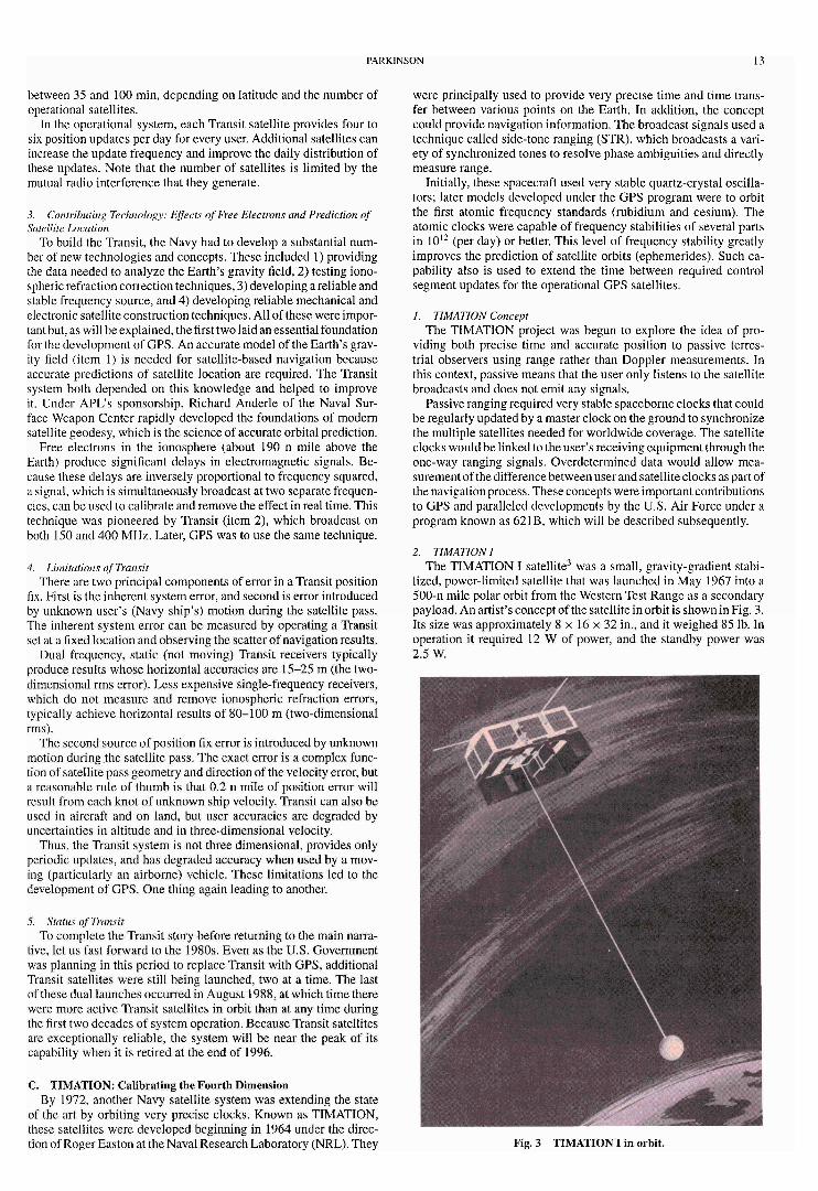
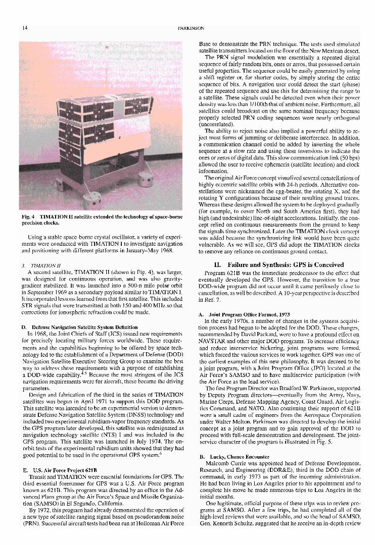
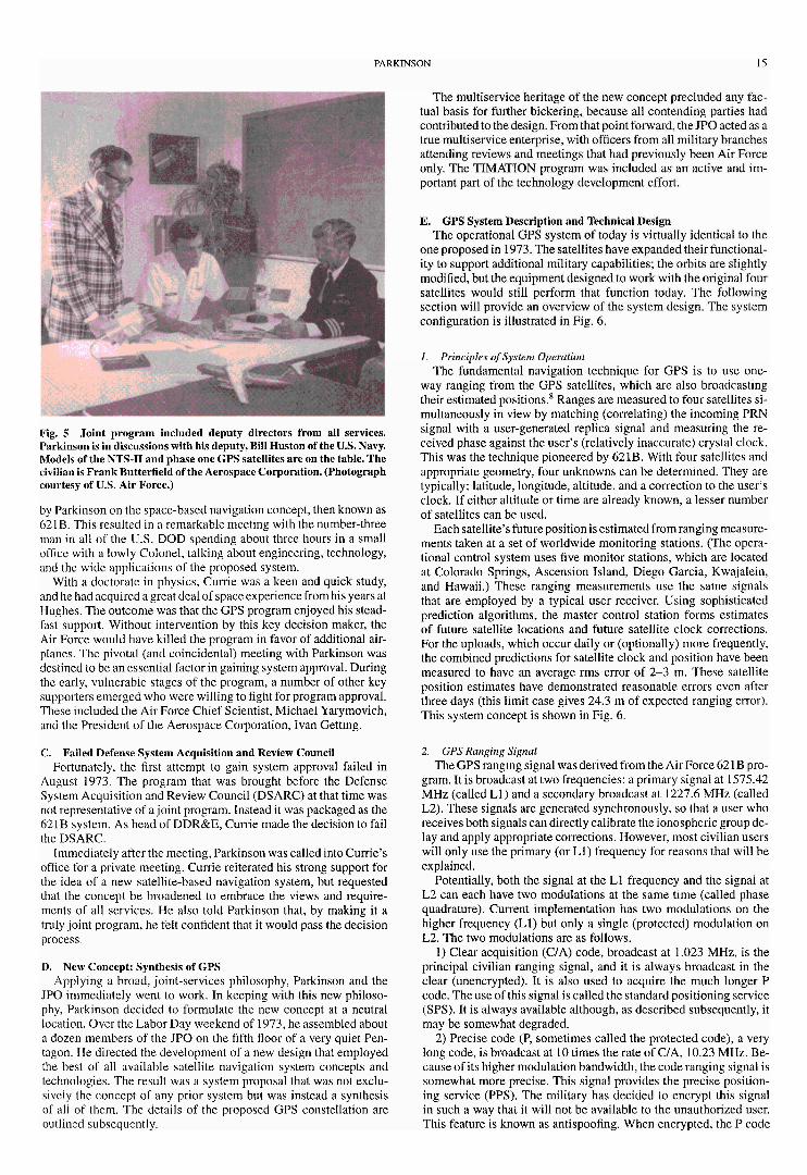
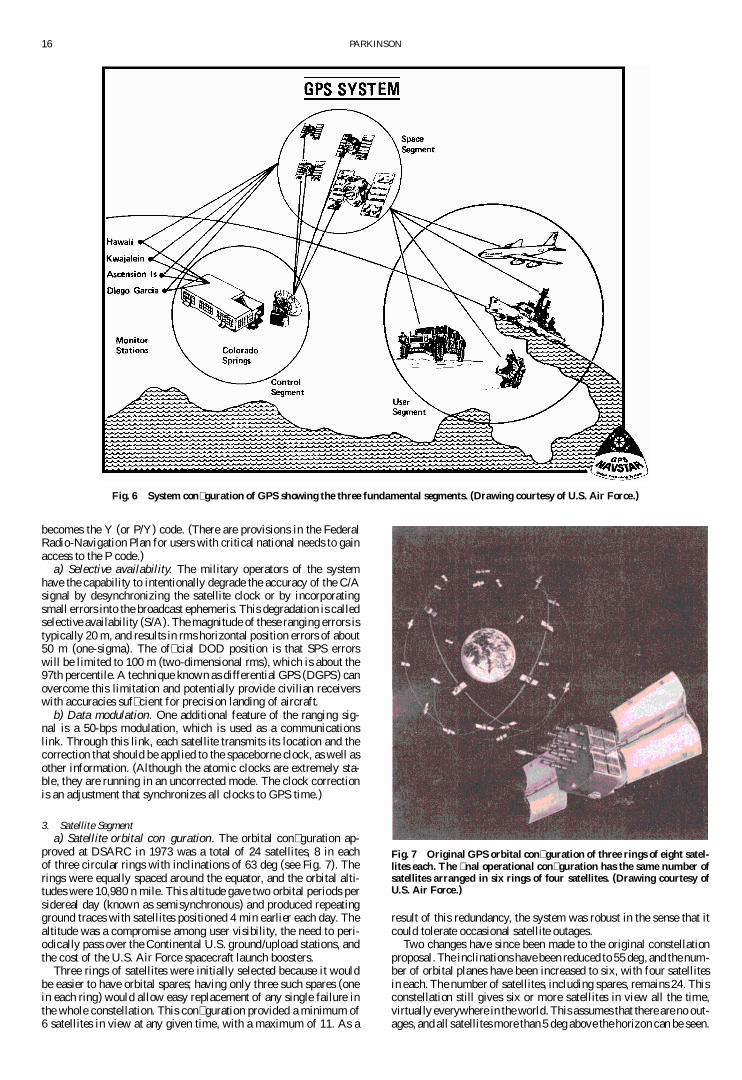
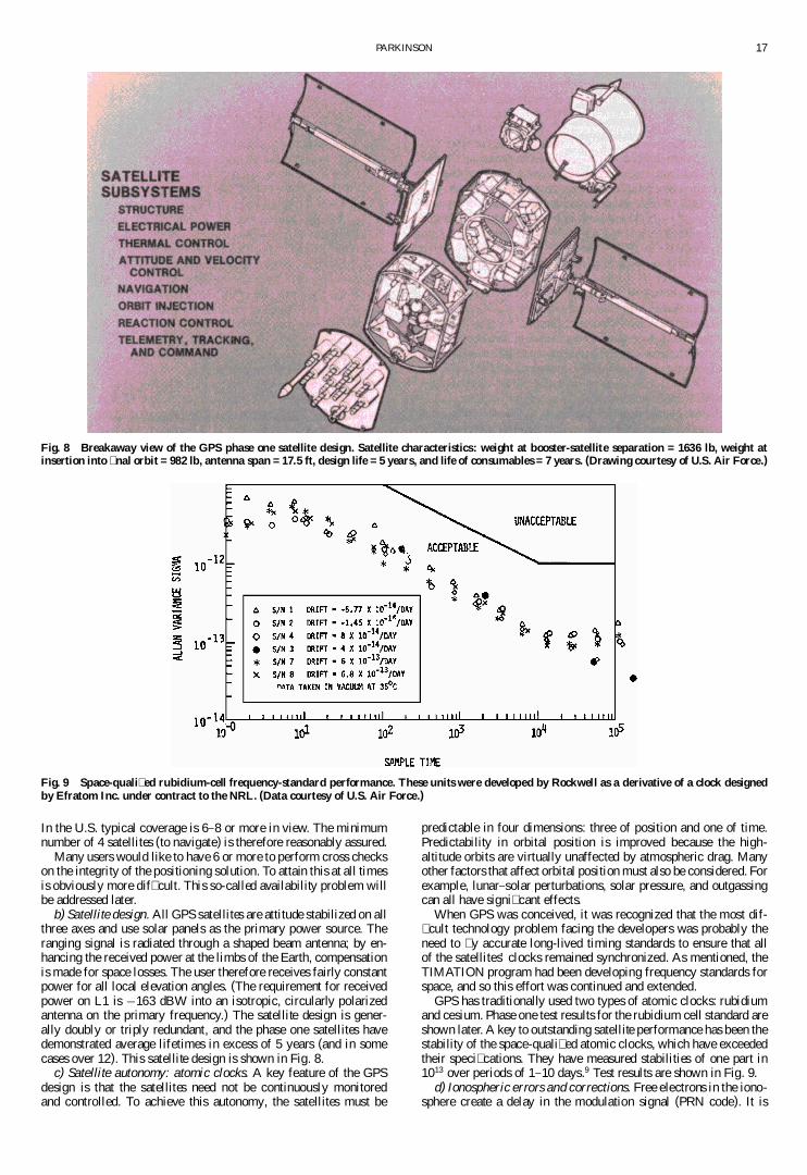
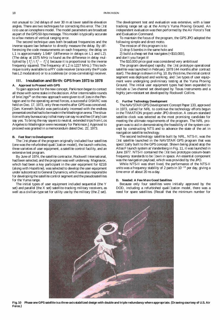
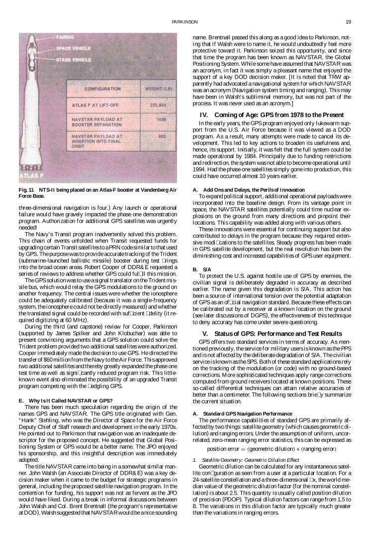