Embed Size (px)
Citation preview
__ _,
. ....
c:J >-
:SURF,AU OF RECLAHATIOU HYDRAULIC L.rnORA'l'ORY,
CfnCE ., r ra. PY ~ri (. ~f;j;
UNITED STATES WHEN BORROWED RETURN PROMPTLY DEPARTMENT OF THE INTERIOR
BUREAU OF RECLAMATION
HYDRAULIC MODEL STUDIES !\OR THE
REHABILITATION OF THE OUTLET WORKS AND \
SPILLWAY FOR &HERBURNE LAKE DAM--
.,
MILK RIVER PROJECT, MONTANA
Hydraulic Laboratory Report No. Hyd-454
DIVISION OF ENGINEERING LABORATORIES
COMMISSIONER'S OFFICE DENVER, COLORADO
August 7; 1959

CONTENTS
Purp.ose . . . . . . . . . . . . . . . Conclusions . • • • . • . Acknowledgment • • • • • • . • • . Introduction . . . . . . . . . . . . . . . The Model • • . . • • . • • . . • . Investigation • . . • • • . . • . .
Conduit Outlets and Flip Buckets . . • . • . • . Scheme A Outlet Works . • • . •
Outlet Works Using Slide Gates . .
. . . . .
Outlet Works Using Radial Gates . • . . • • . . . • . Scheme A Spill way . • . • • . • . • . • • • • • . Scheme B Outlet Works • . • . • . • • Final Design--Outlet Works and Spillway . • •
Outlet Works . • . • • • Spillway . . . • . . • • Flip Bucket . . • . . • • . . • • . . • • .
Location Map . . . . . . . . . . . . . . . . . . Outlet Works Layout and Dams Section (Existing). • • • • . Gate Tower (Existing) • • • . • . . . . • • • • • . . • . . • Proposed Revisions for Rehabilitating Structure • • . • • 1 :15 Scale Hydraulic Model--Schematic Views • . • . 1:15 Scale Model . . . . . . . . . . . . . . . . .... 2, 330 cfs Outlet Works Flow From Initial Conduit Apron • • • • 2, 330 cfs Outlet Works Flow From Final Flip Bucket • 3,880 cfs Combined Spillway and Outlet Flows
From Final Flip Bucket • . • • . . . . . Tail Water Curve and Piezometric Pressures
for Outlet Works Flows . • I. . . . . . . . . . . . . . . . Scheme A--Outlet Works Flows at Conduit
Entrances and Exits--Reservoir Elevation 4730 Scheme A--Outlet Works Flows at Conduit
Entrances and Exits--Reservoir Elevation 4750 • • . • . . . Scheme A--Outlet Works Flows at Conduit
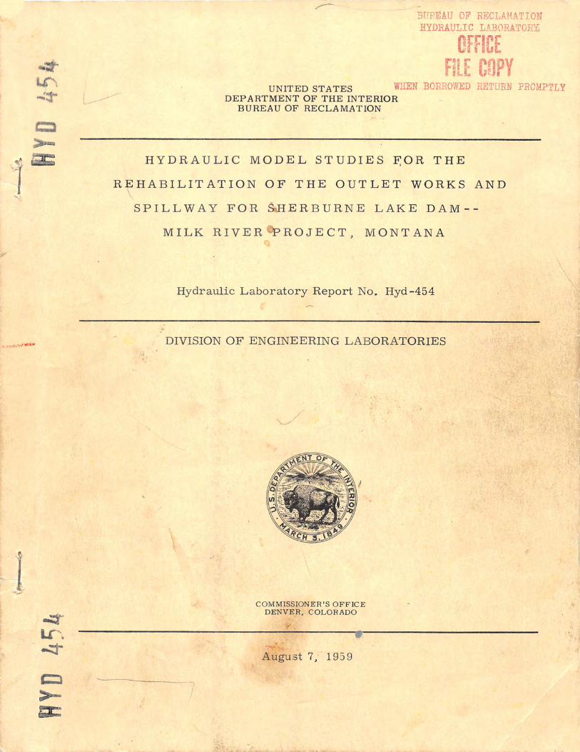
Entrances and Exits--Reservoir Elevation 4770 • • • • • • . Scheme A- -Single -gate Outlet Flows at Conduit
Exits and Hydraulic Jump in Conduits . . • • • • . • . • • • Proposed Top Seal Radial Gate Installation . • • • . Scheme A--Spillway Flow of 1,000 cfs . • • • • • Scheme A--Spillway Flow of 2,000 cfs • • • • • • . Scheme B--Outlet Works Flows at Conduit
Entrances--Reservoir Elevation 4750 ....•.. Scheme B--Outlet Works Flows at Conduit
Entrances--Reservoi:r:- Elevation 4770 • • • • • Plan and Section--Outlet Works Rehabilitation • • • . • • • • •
i
Page
1 1 2 2 3 4 4 5 5 5 6 7 7 7 8 8
Figure
1 2 3 4 5 6 7 8
9
10
11
12
13
14 15 16 17
18
19 20

CONTENTS (Continued)
Intake Structure--Outlet Works Rehabilitation Intake Strµcture--Outlet Works Rehabilitation • • • Raising Spill way Dike . • . • . . . . . • . . •
ii
------.---
. . . . Figure
· 21 2·2 23

UNITED STATES DEPARTMENT OF THE INTERIOR
BUREAU OF RECLAMATION
Commissioner's Office--Denver Division of Engineering Laboratories Hydraulic Laboratory Branch Denver, Colorado Date: August 7, 195 9
Laboratory Report No. Hyd-454 Compiled by: W. P. Simmons, Jr.Checked by: W. E. Wagner Reviewed by: J. W. Ball Submitted by: H. M. Martin
Subject: Hydraulic model studies for the rehabilitation of the outlet worksand spillway for Sherburne Lake Dam--Milk River Project, Montana
PURPOSE
Studies were made to determine which of two spillway and outlet works arrangements was hydraulically better for modifying and improvingthe badly deteriorated, existing control structure.
CONCLUSIONS
1. Scheme A, which places two new gates within the inner control tower, produced much better outlet flow conditions than Scheme B, which places the gates between the inner and outer towers (Figure 4).
2. The Scheme A spillway, located on the outer tower and discharging down between the towers, performed satisfactorily ...
3. The initial bellmouth inlets ahead of the Scheme A gates were unsatisfactory because the surfaces curved too abruptly and produced severenegative pressures at large gate openings. The more generously curved inlets shown in Figure 21 were not studied by model tests, but are believeto be satisfactory for prototype use. /
4. The transitions from the flat floors of the gate passages to the curved floors of the conduits should be/ shaped so that abrupt changes in alinement and consequent severe negative pressures are avoided (Figure/ 21).
5. A flip bucket with wing walls is necessary at the outlets of the discharge conduits to properly direct the flow to minimize river channel scouand structural undermining (Figure 20).
6. Radial gates perform as well as slide gates in the Scheme A arrangement.

7. The Scheme B arrangement directs outlet flows against the inner walls of the conduits where the sediment and gravel being transported would produce abrasive damage (Figures 18 and 19). The flow also climbed the walls and crossed over the conduit crowns to produce undesirable conditions in the tunnels. Scheme B was therefore considered unsatisfactory.
8. Scheme A offers definite hydraulic advantages over Scheme Band is the better choice for use in the prototype rehabilitation program. The final design shown in Figures 20, 21, 22, and 23 are based on Scheme A.
ACKNOWLEDGMENT
The designs discussed, tested, and developed in this study were the result of close cooperation petween the staffs of the Spillway and Outlet Works Section of the Dams Branch .and the Hydraulic Laboratory.
INTRODUCTION
Sherburne· Lake Dam is an earthfill structure completed in about 1918 and located on Swiftcurrent Creek in northwestern Montana (Figures 1 and 2). A gate-controlled overflow spillway in the left abutment, and an outlet works through the dam, were provided in the original structure. Unstable foundation conditions which developed during the construction period necessitated completing the spillway on a temporary basis using timber construction. Continuing foundation displacements and deterioration of the timber eventually required the abandonment and complete closure of the spillway with an earth embankment. Since this closure, all flows past the dam have necessarily gone through the outlet structure. The performance of this outlet structure was never satisfactory due to vibrations on the cylinder gates and surging within the towers. Also, the large quantities of debris that flushed through the system tended to bind the gates. These d·e-ficiencies, added to normal deterioration, resulted in the cylinder gates becoming inoperative a number of years ago. During subsequent years, regulation of all flows was by the six slide gates in the passages leading to the intake structure (Figure· 3). These gates were originally intended as emergency gates, but recently have been used as service gates and were the s.ole means of flow regulation in the structure.
The general deterioration of the intake structure and the insecurity of operation without independent emergency gates have led to a gen-·eral .rehabilitation and revamping of the structure. Now. both a spillway and an outlet works will be combined within the tower. The original spillway in the left abutment will remain inoperative and the earthen dike across it will be raised and strengthened.
Two plans, or schemes, were proposed for modifying the tower. In Scheme A, two service outlet gates would be placed within the inner tower, and a spillway would be placed on top of the outer tower (Figure 4).
2

With this arrangement, the outlet works flows would discharge in line with,and directly into, the two outlet conduits that pass through the dam to the river. Spillway flows would pass over the new crest, downward through the passage between the inner and outer towers, and into the outlet conduitThe spillway crest would extend only about two-thirds of the way around thtower because this provides all the crest length needed to pass expected dicharges. Scheme A had the advantages of directing the outlet flows straighinto the conduits with minimum disturbances, and of relatively large spillway discharges with little rise in reservoir elevation due to the long crest.It had the disadvantage of additional cost.
In Scheme B, the two service gates would be placed between the inner and outer towers, and the spillway crest would be cut through the innertower (Figure 4). The outlet works flows would be directed at an angle to the lin,e of the outlet conduits and flow disturbances were expected at the tunel entrances. The spillway flows would pass down in the inner tower and directly into the outlet conduits. Scheme B had the advantages of a less expensive spillway, and of directing the spillway flows straight into the conduits. It had the disadvantages of more turbulence at the conduit entranceswith outlet works flows, and of reduced spillway capacity.
To determine the relative advantages and disadvantages of the twoschemes, and which would be more suitable for use in the prototype structure, hydraulic model studies were made. The models used in these studies, and the results that were obtained, are discussed in this report.
THE MODEL
A scale ratio of 1 :15 was selected as the best compromise betweesize of model needed for accurate results, and the construction costs, laboratory space, and water supply limitations. The model consisted of a large head box containing the intake tower and gate assembly; the conduits; and the tail box containing the conduit outlets and the river channel (Figure5). The metal-lined wooden head box contained a rock baffle for distributing the flow to provide smooth approach conditions in the reservoir, and a representative section of the earthfill dam. The outlet approach channel and control tower were situated in this earth dam section (Figures 5 and 6APart of the outlet tower extended above the specially shaped downstream enof the head box while the remainder of the tower with the outlet works propwas exposed beneath the box (Figure 6B). This construction allowed accesto the gates and conduits for operation and for visual inspection of the flow.To facilitate this inspection, transparent plastic was used on most of the
· model. The downstream portion of the conduits, their outlet structure, anthe toe of the dam were located in the metal-lined tail box (Figure 6C). A section of river channel downstream from the conduit outlets led to the tailgate used to regulate the model tail water (Figure lOA).
Suitable point gages were provided to measure the reservoir watesurface elevation in the head box, and the tail water elevation in the tail boOne-sixteenth-inch-diameter piezometers were placed in the bellmouth entrances ahead of the gates, and at critical areas near the gates and in the
3

conduits, to enable determination of the pressure conditions. The pressures were read in terms of feet of water on single leg water manometers. The rate of flow in the water entering the model was measured by calibrated Venturi meters in the permanent laboratory supply system. The water leaving the models was returned to the laboratory reservoir for recirculation.
INVESTIGATION
Conduit Outlets and Flip Buckets
Tests were first made to determine the outlet portal design needed for discharging water from the conduits into the river channel without producing excessive scour in the channel and on the toe of the dam. The existing apron at the end of the conduits was 20 feet long, level, and with side walls spaced 21 feet apart. The distance between the outer walls of the conduits was 14 feet, which resulted in 3-1/2-foot outward offsets between the outer conduit walls and the side walls of the apron. Experience has shown that these offsets or setbacks are undesirable because the flow spreads after leaving the conduits and impinges on the walls to form large, undesirable fins. To prevent this spreading and impingement, the walls on the model apron were placed 14 feet apart and flush with the outer conduit walls. The apron was set at elevation 4718. 5 and was level with the bed of the river. The walls were 8 feet high.
Tests showed that as the water discharged from the apron and passed along the riverbed, it caused severe eddying and scour (Figure 7). This scour occurred not only in the riverbed, but on the toe of the dam, and the apron was seriously undermined. Also, the walls were too low, and large quantities of water poured over them and onto the flow emerging from the conduits. This flow condition tended to depress the jets and increase the scour.
Greatly improved conditions were obtained by installing an upward curve at the end of the apron to form a ski jump or flip bucket, and by rais.;.. ing the wall tops to elevation 47 32. 0 (Figures 5 and 8). The radius of bucket curvature was 15 feet, prototype, and the curve was continued to produce a 4-foot rise above the upstream apron floor. Forty-five degree wing walls 15 feet long were added at the downstream ends of the higher walls to protect the structure from undermining.
This flip bucket and wing wall arrangement lifted and directed the moderate and high velocity flows to greatly reduce the eddying and scouring near the dam (Figures 8 and 9). Low velocity flows passed smoothly over the bucket lip and into the tail water (Figure 11). No appreciable scour occurred. The wing walls protected the bucket from undermining and reduced the erosion on the toe of the dam at all flows.
At small discharges and low velocity flows , hydraulic jumps formed in the conduits due to the back pressure, or depth, created by the 4-foot rise
4

of the flip buckets (Figure 14F). These jumps took place without undue commotion, but pumped a great deal of air out of the conduits. This air can be readily supplied through the spillway passages when the reservoir is below crest level. When the reservoir level is above the crest. the vents at the outlet gates will meet the air demand.
The 14-foot wide flip bucket with high training walls and 45° wing walls was considered satisfactory for prototype use.
Scheme A Outlet Works
Outlet Works Using Slide Gates
Water passed smoothly through the two 4-foot wide by 5-foot high slide gates within the inner tower and entered the outlet conduits. Disturbances then occurred due to the spreading of the jets as they left the 4-foot wide gate conduits and impinged on the inner and outer walls of the 6 -foot wide tunnels. No confining walls could be placed along the jets on the outeside of each conduit because openings were needed for the entry of spillwayflows into the conduits. The inner sides of the jets from the gates were unconfined also.
Upon entering the conduits, the flow reached the transitions wherethe flat floor of the gate passages blended into the curved inverts of the conduits (Figure 5). This transition, which was most severe at the walls, aggravated the tendency for fins to form in the conduit. Fortunately, the finswere relatively thin and did not seriously affect the performance or the frepassage of air through the conduits. Pressures measured at areas believecritical on and near the transitioning surface were for the most part positive at all gate openings and reservoir elevations (Figure lOB). Pressuresobserved at Piezometer 4, which is on the curved invert just downstream from the end of the transition surface, were slightly below atmospheric. Tpressures were not low enough to indicate cavitation in the prototype structure. Rounding at the intersection of the transition and the conduit inverts would reduce the tendencies for subatmospheric pressures and provide a greater safety factor for local pressure reductions at surface irregularitie
Single gate operation was entirely satisfactory in the tower and conduits. A slight sideward flow component existed in the flip bucket, but no undue difficulties were caused by it (Figure 14). When only one gate operated, the other conduit stood partly full of water. The second gate could be satisfactorily brought into operation against this ponded water by opening it reasonably slowly.
Outlet Works Using Radial Gates
A proposal was made to use 5-foot wide by 4-foot high radial gateinstead of slide gates because radial gates might prove less costly (Figure 15). The decreased height of the gate made it possible to raise the passag
5

inverts to elevation 4721. 0, which was level with the intersection line of the curved conduit floors with the side walls. The passage floors downstream from the gates dropped on trajectory curves to meet the existing conduit inverts. New bellmouth sections were laid out using the same design criteria as used on the initial bellmouths.
Model tests showed that the radial gates performed satisfactorily and much the same as the slide gates. The modified gate passage inverts and transitions to the conduit floors produced somewhat better flow conditions on the floor and the conduit walls. The pressures in the corners of the bellmouth sections ahead of the gates were quite low, and therefore unsatisfactory, for both symmetrical and unsymmetrical gate operation.
A later decision was made against using the radial gates because their light construction, compared with slide gates, would be less well adapted to resisting the flow turbulences, pressure surges, and vibrations likely to occur when the conduits fill during spillway discharges. No further tests were made with radial gates.
Scheme A Spill way
Water passed smoothly over the Scheme A spillway crest 'and into the passage between the inner and outer towers (Figures 16 and 17)i Con. ditions were turbulent in the lower part of the passage as the flows plunged into the pool at the base of the intake tower. At flows up to about 700 cfs. the conduits flowed partly full. At larger flows, the conduits filled completely.
Great quantities of air were entrained by the water falling from the crest and plunging into the pool in the tower (Figures 16 and 17). This air was carried into and through the conduits and part of it accumulated into pockets. Upon reaching the portals, the pockets burst forth into the open and created considerable spray. The water, with the remainder of the entrained air. passed reasonably smoothly through the flip bucket and into the river channel.
When the reservoir elevation was raised and the spillway flows increased, the pool within the tower rose. Thus, less drop occurred from the reservoir surface to the pool, and more tranquil flow with less entrainment of air took place in the tower. At a spillway discharg.e of about 2, 300 cfs, the pool within the tower was high enough to submerge the crest and prevent any appreciable entrainment of air.
In the area just above the outlet conduit entrances, the inner and outer towers are connected by a concrete section (Figures 16 and 17). Square corners were initially to be used on the ends of the section. Tests showed that the flow passing around these squares ends had a pronounced tendency to separate from the surfaces and produce negative pressures. Rounded ends on the prototype structure will reduce these difficulties and the pressures should be satisfactory (Figure 21, Section F-F). No tests were made of the rounded ends.
6

Scheme B Outlet Works
The flow through outlet gates placed between the inner and outer towers was smooth (Figures 4, 18, and 19). However, the water from the gates approached the conduits at an appreciable angle and impinged heavily on the inner walls. It then climbed the walls and crossed over the roofs to drop down the outer walls. The action was moderate at small gate openingand became progressively worse at larger openings. When just one gate operated, a pool of water was held in the other conduit by the elevated lip of the flip bucket. This water moved upstream in the unused conduit and then swept around the nose of the pier between the conduits and into the higvelocity flow of the operating conduit.
A serious objection to the design was that excessive abrasive and impact damage would occur on the conduit inner walls where they would be struck by the sediment-laden flows from the gates. A further objection wasthat severely negative pressures occurred on the conduit outer walls at theijunction with the angled outer w:alls leading from the gates (Figures 4 and lOC). This intersection was rounded to a considerable degree in the initialdesign but an even greater rounding would be necessary to obtain satisfactory pressures.
The flow continued through the conduits. alternately climbing the inner and outer walls. The height of climb gradually decreased, but was still appreciable when the flow reached the flip bucket. Unsymmetrical flows through the bucket tended to slightly increase the disturbances in the river channel and aggravate the scouring.
It was concluded that even though the initial cost of Scheme B was less than for Scheme A, the deficiencies in outlet works performance in Scheme B were enough to rule out its use. Therefore, no further tests wermade with the Scheme B outlet works, and no model representation was made of the spill way structure.
Final Design--Outlet Works and Spillway
Outlet Works
The Scheme A arrangement was used for the final design. (Figures20, 21, 22, and 23.) Two 4-foot wide by 5-foot high slide gates we~placed8 feet apart within the center tower. with their inverts at elevation 2 20. O. New bellmouth sections were provided upstream from the gates. T ese belmouths were formed with elliptical surfaces having major axes three times the length of the minor axes. No curved surface was provided at the_ top of
-the passage because it was level with the inlet roof. The major axis of the sidewall curves was equal to the 4-foot width of the passage. The major axof the invert ellipse would, by the same process. equal the height of the passage if a top convergence were provided. In this structure, there is no top-convergence and the flat roof approximately represents the center line position in a symmetrical conduit, insofar as flow pattern is concerned. The
7

equivalent height of a symmetrical passage providing a companion top convergence would therefore be twice this 5-foot passage height, or 10 feet. There was insufficient length within the tower section to allow using this 10-foot axis, however, and it was necessary to compromise with a 6-foot major axis. It is believed that with the moderate heads that act on the Sherburne Lake outlet works, this compromise curve will produce pressures high enough to be entirely safe. No model studies were made of the final bellmouth section.
The conduit walls downstream from the gates were made parallel to keep the water from spreading excessively (Figure 21). After leaving this straight conduit, the water travels a short distance without sidewall confinement, and then enters the outlet conduits. To reduce the tendency for fins to form: and negative pressures to occur, the floor transitions from the flat to the curved surfaces were made with curving elements. These curves will be produced in the existing prototype concrete by dressing the present straight surfaces.
No model studies were made of the final design outlet works because of inadequate funds. Thus, there are no model-determined calibration curves. A compnted discharge curve is presented in Figure-20.
Spillway
The final spillway was about the same as the one tested in the model (Figure 22). The principal difference is that the final crest extends around to existing walls on and in the towers instead of stopping at new walls that would have been constructed. This resulted in a longer crest,
· and a probable tendency for minor flow interferences at the crest ends. Trash bars and their necessary supporting structures were also included on the spillway. No model studies were made of this final design and no model calibration curves are available. A computed curve based upon the increased crest length, with allowances for trash bar losses, is presented in Figure 20. ·
Flip Bucket
The final flip bucket was basically the same as the one developed in the early part of the model test program (Figure 20). Two design improvements were made. These consisted of continuing the curved inverts of the conduits downstream to where they intersect the upward curve of the bucket, and providing a 3-foot wide, flat top downstream from the bucket lip. The performance of this bucket is expected to be satisfactory for all outlet works and spillway flows. No model studies were made on it because of inadequate funds.
8

·40'
R.IGW. ---~ ... --
G L
I IP. ((tjlll
o~ ~ I-~ e-f~ :'4·1 ~ ,-dJiHel,m i. ~~" ·~ .. ..,, ~'"\ -~--I,~~-
• P. I ~ ,--,-\ .. . ~· ' 5o_/__ - -- -- , \<#; . I ----===="'
":,....._,\,..-J , I«b•e~
. \ .. ,,, ,.1f..-,- -§~-
BURNE LAKE DAM-
114°
i I 49\·-~
\<fl: L-. / ' . J ~ ~-,;
' ..J
_)~ ( :Ei
.\ i -~
( e>JJT Lake ~o.rephine
I . /
\.~;::-~· ~' .. \ , I ,. ''-\_ , \... N A
~
40' r __ _ (; I T-...,,.li ,·
~; ~ ) ' \ ~\-, , ~:uru. "'~ L,ak,
'
'· ( ' t'
i ~q '!1/
I /·'\ 0.V"'""',-.:._ .. •J '
3d· -·
30'
' IL I
:i:::ol 10'
~ - ~~:
,. ------~~ -c. .... - :-..:. ----·---- ~ "
t
R.IIW.
.,r'),.,...J'
+ - - '. ···--~-· --1- - -· -
-tJ("'7 ,:/
113' 5?' R.I0W.
.._ ___ .,. '·"·· >) l 5/, 5.J'~A-- I >~
. : -l I
~
i i
I
- ' ·--·--~!
1
~ r1T.35N.
--+-~ 7
' 11 \ i I :=::s q1 lb--ct:~ &7' I)~ V II I I\~ \ i "r
, , . ~ Hn7".q, _ , , . ., , \\ I
A R K
. \~ ?,O<
~)
!,-r~ __ \._
-~1
.. • 'F'k
.
' ---·- . ··-·.· -~!-I J.. 0~' ·-···+----
1 i
s I----··· • • "' "" i, E- I -t R-,----· -· --~ ~ ~ ~ ~:L ~- I
I ~. j----t---- ~--- ~~;i-·
i . ~ '\
_..;, ·----
~ ,,
.L
I
i T.34N.
b : --1Nl - ·l] - T,33N.
·T.32
._v __
FIGURE I REPORT HYO. 454
LEGEND
-=-(ill-@-=--='"' _u. S. a STATE HIGHWAYS
,-=-----------------' ROADS
~
RAILROAD~
CANAL
f;· //,//// ///, :~] INDIAN RESERVATION BOUNDARY
k''0-.~~'""~~-::Z-,'-,\\~~1 FOREST BOUNDARY
N
• I
I
t i l
. SCALE OF. MILES
11-19-!JS I CONSTRUCTION MATERIAL!J SOURCES ADDED 0- 4',m
UN/TEO STATES DEPARTMENT t;JF THE INTE.RIOR
BUREAU OF RECLAMt4TION
MILK RIVER PROJECT- MONT, ST. MARY STORAGE DIVISION
SHEtiSURNE LAKE' DAM LOCATION MAP

/---/
/----
( /; ! /s ~JA'' -/(
'>:,
" ~
Jier0
Tem,oorury
H'eodea 17ume
/4b Stooe to be le55 tllon 15 'm 1/Je tJ/mea.51tJ/J normo/ rot!?e .5i'o,ae:·>
~/3/~;~~rl,?~),;/~·wdj 9%
jo-
AIOT[0
FIGURE 2
REPORT HYO. 454
lren:lles Ill/eel mlf 4-hter,o/ .50me as ,fq}ace/J/ !'arts o/ /}am except !//at frex,les m whcl, iJ/77//7 R,Ms ar<" /a,d s/4?#' A- /;#eel ,,-,1// Screened' 6ra11:'/ to a c/eplll or 6on-r tA,· Lin:va A,,a-s.
: 6mm, Co,!,,!,j,5 0/1(7 L'!ou.Af-rs -----------
:-;----:::: = ~~_Oro/,,,,.,/6/Vt/al~~ce-,c'. =_-==- =:_-:_::-~-=--=_-::: - ' J.?~Per;?'ous L'!o,.h'e,r Chy - - - - - -
........ ---·~7~~
MAXIM/I/If 5fCT/tJ# >- zz·h, , ,. tJ!--:-f.;.·~ 5
~ll,lmperrhus tJou/d',-r,.bf/ '-i'O' ~,b:-r-~-x----:.. ___ -, ·-----Neor Ends of Dom !his
Oi5tonce diminished fo /0'
Swift.current 84a?'lt1'5£.l:V'Pm'Ch'?,a- ,;,, ;zze,79/,/;5 /ad w,/ll {Jt:,:-n Jo,ill'.5.
~
4195 90
80
~ 70
~ ~ 60 j
~4750
" ·<> 40 '§ l.: ~ 30 I
4720
41Z5
~~/: -------------- --------------- ------/ __ ,,,--
/
/ PL,&/N / 50' 100' zoo' '""' vv 5CALE
V /
/ I
5cre-t:necl 6rar~/-
~ ----'ds --- --.f-
;;-,.,~ltJ'~iiTltftW ,P//'f t),f',4//;'.5
~
---i--:.i:_ Impervious BoulderC!ay
5creened 6n:7re/-/ -~j!O~~ f t ltJi?T,f/rlflJ PIP£ 1)/?AIN ~
0 5' 10' ~
SC4LE
[
lll'lfk« dep/h o/fil/ 1s less //Ja/7 6t?' ,4 ~ 21• • , • ' · 6t?' to !JO'
lL' ' ' ' ,. ' !0' ' /00'
...... '.<!, ..
f
Cl:)
'k, ~ :tS lo
~~ "'" n, ~ " ;q ~"'i
i"o/''4"J'~~7
11'5£I. 41931
1 (CIC§.c of_{}_qrf', -
t~J.1J< fl41L'0'
/0!''/j'
~· .,. , l l I
ill--'6"ffk,,-c/eptl!ot'/1//1s kss/ll-<;n 60' 8· 11'9' " • " " 60/o 80'
lf'--'0' " " · • • 80' /00'
SfCTION TlfRIJ O/JTLfT CON/JIJ/T
..,. c33·'o'
---fb -
·141'/'·
SfCT/0NAr0t/T(.CT • 1 - - - w -
5C4Lt:
10 zo 30 4() so 60 ,o bo O
$' r,1 I . 1 1 1 1
, r, I , I I 1 11t· ?,ap,,c1fl/ 10 Tlious,aao's o/Acm lee! SCA L E 5CAL t: /fOTl --Tl;;s [}mwli>; compdeo' /'rom [}es1i;11 !}row1nqs
CAPAC /TY C t/RJ/e made 111 tile lfosllinqt0/7 amt Project 0/'rices
p,
ff,11/f/5
f)cPARTMfNT or TMf" INTf"/;'NJR
UN/TC£) ST.4TfS ;PCCLAMAT/ON SC/PY/CC
MILi( RIJ/cR PR0JcCT- MONTANA SHfR/JtJl?Nf LAKES Ot/TL ET WORKS
UIYOI/T AND fMM 5f'C T/ONS
£)n:,wn·-_____ t;_,1J~t_ ____ .l?ecommended·:_
Checked:_ll,~.~-----Ap;,ro=d_0 ____ 0if:L_,_~-·-
CJ\M I :~-f ~--,,uenn-~c~.l~H'l'~cv.l/6-C-/41

,•
rr~::=::::;:-;:;;;:;:;;:;:;;:;:;;:;;;;:;;::-;;-:-;--;:-:::ii=;;";'~=-1---:::;:::::======:-=----_-__ :=::::;---------~--------------, ::o fTI lJ 0 ;a
~ I'<::! 'ti
~ ~ ~ i I'<::!
rS! ~ CJ)
C) C'i ~ l::i
~ 12:i
9 - , ·' /5'0'
0
;
\ i
·co· . .
,Pod,i/5 c6ate Srems qt 1";, ~--Romos C 60/e 5/ems at fl 4748.· '- · - -'S, ~ fl 4735.
:;,;-,·,
\Lf ,--... --·-r
o(Wt11-· fcJ1A-
- /)(5'Tre1sh !Jars, 7'C.loC. j" Beorir,p ?!oles urder J !Jeoms not 5h<Jwn
··--IZlJ~------
-i rertex of {one ~f ______ --.-~
~
:-,. ..
~. I!, •• ('> .• (. .... ... ·.;lo.
10n J
p,:743
D .
12·0-~- ·
T/J.-ckness of rloor decffoses to #'at C:Ulo#"H&II 0 .fl/9.247otdownsllwmfd;<-of'tfo/e.»II
NOTES" I Le17r7//J of f/Jn,-e 1/flfler 6wrd P,pes // 0 • Le09'IIJ ;
of /o,rer 6uord P,pe on5tem 5, !5'5f' ' Z /?ear/J/afl/J~ e.rlendfvl//Je/9/Jlofdou/J/dl711'
(}//Jerlltaplm:,gmse.rtend /vii /Je/y'/Jlo/ dovok ff,,// mJ/, threeO,oen1~s.LowerOpemll9eKlends /20Po.reJJ//ol ~cl 47/S.S,m/d/kD,cen,,%'4b/J,J,-,.,51/hl fl .-/735 Q/IP llflperOfle/7//J!f' 4i7//ore 5t//q/fl 4750
3. Concrete Reinforcement not shown.
,z· o 111 rrrrrJ
- 4!364'
~-12·-o:r--
"' .
. ' .
i
NOTf rorulj/Jnder oote lio/St 5ec LJraw1nt_7 /6 - C-/9
' <b
nrTJ oon noo 00_0
C=!er11e;q!,!s md ~o,e,, iirC1;/hclerGo,fa shown '. on DMJ. 16 C·/1 Upper Ends of Cr;/irdu Gak : 5fem5 lapr,d for /" Eye-bolls lo r,air, Wrre n'or : from Co(/,?/erwe;ghb
ono nno DOD 0_0n
. ' "
i 0
JI •• < ,J
" . ". 0:. b
D477Z
~ • 0., t.. < ~,. tr
0, • ~ ,._f;j
(?) '
i p
I q •
'0
I' • p
' " '
- _j_ .d 47q_}_,Q76'_
OIi tJe/15hns lilr 5lems4&5 :someos tor 5tem 6.
119/JJ (Inside)
'/'.5!eel Ltili?q. " . 'j' Straps
,..J_._. 1z'x1z' £14701
, "
7 /}
, b
r- - ~ ' c::,-
f-~-s~~ ....
D.4700, - ·-r--
,.(.-c. <::,' '•
-·, d , ~-
__ .. _'-/3'0"/J. 0 ~ • ,;:, _:_.__ •.• _J""
SfCTDYr?L. cffl/l7TIOM c-£
-l
0 z I ci I
lJ ;a fTI ({) ({)
C ;a fTI
;a fTI ({)
fTI ;a < Q ;:o
0 C -l r fTI -l er,
::0 1"11 "CJ 0 "Tl
~ G) C
I ::0 -< 1"11
!,J w ~ 01
/fOTf.-T/Jis /Jraw1i,q comp1M Ii-om Oe5ign /Jmw,i,gs mode in t/Je Hbs/J1i,qton and Prryect Or/ices
,.._,______..___ ___ _._ _______________________________________________ ,_,1~

512
~~{----t:? :_::~: ,,:;
SCHEME A - Outlet gates in inner tower with spillway flows passing between inner and outer towers.
Outer tower--
FIGURE 4 REPORT HYO, 454
--6'x8' Horseshoe outlet tunnels
SCHEME B - Outlet gates between inner and outer towers with spillway flow passing into inner tower.
SECTION X·X SYMMETRICAL ABOUT <t.
(SCHE.ME. A)
SECTION Y-Y SYMMETRICAL ABOUT 't.
(SCHEME B)
SHERBURNE LAKE SPILLWAY AND OUTLET WORKS
PROPOSED SCHEME A AND SCHEME B REVISIONS FOR REHABILITATING STRUCTURE

N
--8" Water supply
'--Rock Baffle --
= ,b a 0
80"
c• E.
0. 0 x ,..-)
Ng
24" --
r7IM MI, --- -A
5.-0
"
Spillw
ay an
d
inn
er sh
aft
r 7 o
z 0 6,
— -1 me r
DDz r
u)
ri
z r
TZ:1 0
_a
-I-
r- 3 o
• 0 -h 0 a 3
>1 ° 0"
1
—4
0
"A fri
CO -P.
I _ '•\,, ,c-1 o„
r. <-- 1;YO '"
(4>.
6.08'1->:4 -5.50;44c 6.57" ›;<-4.33",
H-H
-wap j.o
apt)} w
oa
4sd
n
0 fl
0
6'-o"
0
—J-
< 216'
9
3
O
re. N
co J1
-o r
z
CO fl
0
0 ,-Tunnel ‘‘, portal
0
00 -
6-0"
V
O C —4
r
z
z
z
P1
r
<-3.67 A 7-33"->
Lod'
46.96"
o.4o 0.354,:<- •.;
[32°"- ,0.24"R;1 ->12.174
A
b_5.6 .0 01:3
A r rn
f A to .O ▪ N
2.08%,
320" NO
LLD
3S
A J
7ri cf) > 0 D0 m
m r-
• Z > 11:7 C — 0 x-
0 Z pi C);l m C 0 1— a < —4
M () rn r-
--ID
co 0 op in .—Nrn — -1 in
0„, 4— 2)
=Z — N 0
3 ,
co 0 7 C -4
O
rn
7 . z8”
5.2.2"->
- 6.40"--›
_Y
r
r
fl K 03 0 3
rF)
143
<0.80"
8.48"-7!->4
k..;„ 0 0 co :s0 N
m ,)
A.
7S •
)1-)1
NO
lit A
31
3
-r 0
2 N./

A. Interior of head box with approach channel and Scheme A spillway.
B. Gate and tower section - Scheme A.
C. Outlet conduits leading to tail box in foreground.
SHERBURNE LAKE SPILLWAY AND OUTLET WORKS
1 :15 Scale Model
Figure 6 Report Hyd 454

Figure 7 Report Hyd 454
A. Bed prior to tests • B. High angle view of now.
. C. Low angle view of now.
D. Erosion after operating model 1 hour.
SHERBURNE LAKE SPll..LWAY AND OUTLET WORKS 2,330 cfs Outlet Works Flow from Initial Conduit Apron
Res. Elev. 4784 T. W. Elev. 4728. 2 1:15 Scale Model

Figure 8 Report Hyd 454
A. Bed prior to tests. B. High angle view of flow.
C. Low angle view of flow.
D. Erosion after operating model 1 hour.
SHERBURNE LAKE SPILLWAY AND OUTLET WORKS 2, 330 cfs Outlet Works Flow From Final Flip Bucket
Res. Elev. 4784 T. W. Elev. 4728. 2 1 :15 Scale Model

Figure 9 Report Hyd 454
A. Flow pattern •.
B. Erosion after operating model 1 hour.
SHERBURNE LAKE SPILLWAY AND OUTLET WORKS 3,880 cfs Combined Spillway and Outlet Flows From Final Flip Bucket
Res. Elev. 4793 T. W. Elev. 4730. 2 1 :15 Scale Model

Sit
4732
----
ti "'
I----I 4728 ~ I--"'
i-----z 0 L.--I- L---<[
i;'; 4724 ...I /"
:..,..-----
"'
~ :c
ti ~ I
II) 0:
I
. 500 1000 1500 2000 2500 3000 3500
DISCHARGE-CUBIC FEET PER SECOND
A. TAILWATER ELEVATION
0.75-, A-<ll _.G::J·. SECTI01N A-A • .. '. J:-1.25'+,t+i ~-0.25' Flow>- _±t--:J!e~2~-;'r4-;:--4 _____ -f \..... ! _,)
El.4720.0-i
,0,: -~ ••• .,.d_:_ .. ,..,. ·. ·. •,•p, ..... -..... ·-··.-.- • .c:..-.-·:-.-~.-~ · .. j:::'.•.'I. .·,4:·.•-. .q, -~-- • •••• -;~. ·-·· .. _.; •
~ I --~L-~r------l--__j __ ::_Alo-l=-----i~2~--~-'l~:::::==:t2~~~-==~ :;; 101-- /' 1:3 ____ ..... 3y "'n.-L 1-====Jt::::J:;;;~d:::::l:::~;1;;~~~!~~~~-~t:::::t~~~~;t::::j 1--'l _i...----~ 0 II)
!:/ 10 ::::, II) II)
"' 0: --Q.
"' Q.
~_:- - IR' ... _5 0 :-E-:- - - -1- - - -- -i-- - -i-- - - -- _.__ - -- - - - -
.......... ...____ 4--,~ -----
~ -10 o: o!:-----:'10=----='20,,---='30,,---4""0=----s_.,o ___ s._0 ___ 1.._0 ___ 8,._0 __ °"'90'-----'100
n. GATE OPENING-PERCENT OF EFFECTIVE TRAVEL
FIGURE 10 REPORT HYD.454
i
! 4--1 i
I l
1,~
·-··
B. PRESSURES AT TRANSITION FROM FLAT FLOOR TO CURVED TUNNEL INVERT SCHEME A
Piez's @El.4720.6
······· ·-.-::':':
-4
4750 4760 4770 4780 4790 RESERVOIR ELEVATION -FEET
C. PRESSURES AT CHANGE OF SIDEWALL ALINEMENT SCHEME B
SHERBURNE LAKE SPILLWAY AND OUTLET WORKS
TAILWATER CURVE, AND PIEZOMETRIC PRESSURES FOR OUTLET WORKS 1=15 SCALE MODEL

A. Q = 250 cfs. One gate 49% open. T. W. = 4723. 4. A jump occurs in the conduit.
B. Q = 250 cfs. Both gates 36% open. T. W. = 4723. 4. A jump occurs in the conduit.
C. Q = 582 cfs. Both gates full open. T. W. = 4724. 4. Conduits flow full.
SHERBURNE LAKE SPILLWAY AND OUTLET WORKS Scheme A - Outlet Works Flows at Conduit Entrances and Exits
Reservoir Elev. 4730 1 :-15 Scale Model
Figure 11 Report Hyd 454

Figure 12 Report Hyd 454
A. Q = 250 cfs. Gates 20o/o open. T. W. Elev. = 4723. 4. A jwnp occurs in the conduit.
B. Q = 1,000 cfs .. Gates 73o/o open. T. W. Elev.= 4725.7. A jwnp occurs in the conduit.
C. Q = 1,530 cfs. Gate lOOo/o open. T. W. Elev. = 4726. 9. A jwnp occurs in the conduits at outlet portals.
SHERBURNE LAKE SPILLWAY AND OUTLET WORKS Scheme A - Outlet Works Flows at Conduit Entrances and Exits
Reservoir Elev. 4750 1:15 Scale Model

A. Q = 250 cfs. Gates 15% open. T. W. Elev. = 4723.4. A jump occurs in the conduit.
B. Q = 1,000 cfs. Gates 61% open. T. W. = 4725. 7. No jump in the conduits.
C. Q = 2,030 cfs. Gates full open. T. W. = 4727. 8. No jump in the conduits.
SHERBURNE LAKE SPILLWAY AND OUTLET WORKS Scheme A - Outlet Works Flows at Conduit Entrances and Exits
Reservoir Elev. 4770 1 :15 Scale Model
Figure 13 Report Hyd 454
Figure 14 Report Hyd 454
A. One gate open 42%. Q = 250 cfs. T. W. Elev. 4723. 4.
B. One gate open 77%. Q = 500 cfs. T. W. Elev. 4724. 3.
Reservoir Elev. 4750
C. One gate open 31 %. Q = 250 cfs. D. One gate open 6 3%. Q = 500 cfs. T. W. Elev. 4723. 4. T. W. Elev. 4724. 3
Reservoir Elev. 4770
E. One gate open full. Q = 1,016 cfs. T. W. El. 4725. 7 Res. El. 4770
F. Typical hydraulic jump in conduits. Two gates open 42%. Q = 500 cfs.
SHERBURNE LAKE SPILLWAY AND OUTLET WORKS Scheme A - Single-Gate Outlet Flows At Conduit Exits,
and Hydraulic Jump in Conduits 1 :15 Scale Model

512
FIGURE 15 REPORT HY0.454
PLAN SECTION A-A
TRANSITION COORDINATES
. · . .-.· .. · <· :, : ~:. :·-~--·\i.: ·.·.· .. ."!·· ' •• -~· . . ·.·
-: -:-.-. ·<j· .. ·.·.·.· . ·:o· .. ::~:-:~-:::
·..:.·.-.f>: ...... ·.·.·:."'·:
,-ll I 2'-9'Dia. ., Shaft
/--::: • • a- •. • t I
~-------,-''•',a· ., ·::."·,'II I ..,....,,....,.....,.....,,....,...,.......,--,-,·(j·: ... 'c:i.. : \
_::\:~::<·)~!):-/::~/}\(·;~{\::/ i(\\{i, Ary
. . . . . . . . . . . ...
Flow -I I
"o -' 1
I
ELEVATION
. -0 .' · ·.o. . · .... . . . . . . . ' ....... :Q.: p_ •••
. ·-·:·.· .. -:-:0. ~ .
.. o •
.o::J· •
·-· . :."c.:?· ..
. . t?· • : :: : p: .
SHERBURNE LAKE SPILLWAY AND OUTLET WORKS
PROPOSED TOP SEAL RADIAL GATE INSTALLATION
I
X y 0
0.006 0.048 0.171
0.442 1.040 2.091
2.986 3.998
0.897 0.869
0. 788 0.656
0.476 0.254 0.088 0.035
0
~A V

A. Flow over the crest is smooth and the water drops far before striking the pool within the towers.
B. Much air is entrained and carried into the filled outlet conduits.
C. Air bursts out of the conduit portals. The flip bucket performs satisfactorily. T. W. 4725. 7.
SHERBURNE LAKE SPILLWAY AND OUTLET WORKS Scheme A - Spillway Flow of 1,000 cfs
1 :15 Scale Model
Figure 16 Report Hyd 454

Figure 17 Report Hyd 454
--A. Flow over the crest is smooth, and the water drops
only a short distance to the backed up pool.
B. Air entrainment is relatively light. Flow spirals down the conduits.
C. The nip bucket performs well. T. W. 4727. 7.
SHERBURNE LAKE SPILLWAY AND OUTLET WORKS Scheme A - Spill way Flow of 2, 000 cfs
1 :15 Scale Model

A. Q = 250 cfs. Both gates 22% open.
B. Q = 500 cfs. Both gates 43% open.
C. Q = 1,000 cfs. Both gates 72% open.
D. Q = 1, 430 cfs. Both gates fully open.
SHERBURNE LAKE SPILLWAY AND OUTLET WORKS Scheme B - Outlet Works Flows At Conduit Entrances
Reservoir Elev. 4750 1 :15 Scale Model
Figure 18 Report Hyd

Figure.19 Report Hyd 454
A. Q = 250 cfs. Both gates 1 7o/o open.
B. Q = 500 cfs. Both gates 35o/o open.
C. Q = 1,000 cfs. Both gates 61o/o open.
D. Q = 1, 920 cfs. Both gates fully open.
SHERBURNE LAKE SPILLWAY AND OUTLET WORKS Scheme B - Outlet Works Flows At Conduit Entrances
Reservoir Elev. 4770 1 :15 Scale Model

N
oJIL
\ \ \ \
L-t-"-- --- I A
-~-_:_ ~'- -----~---;lPreserve free outlet for -- -·---- embankment dram
~~' -----------------.-..a----J.-Extend 4' riprap to left \ ~o:':\'.::, ~ ,~~-~ abutmentort0o'min. "'-' · ', . ,· } at El. 4725 from £ 0
', •:, • outlet works
Vary side slopes to match existing channel
L E
----+f-+~~+--,--..-. ~+ J A
c,( ,'Is,
-clF
4"
-o-·
3'-o" -~ :, !_
-<J.., 'F L
&• o<_
FIGURE 20
REPORT HYD. 454 f' Dia. expansion anchor baits ( Vertical spacing dee~,_
,, 4'Min.
1' Min. depth saw cut along perimeter 12' Min.- -,,4 - · '· ---#4-lx 4" Wire fabric
of damaged area - - - - _ _ _ ;6~:-24' Moxc: _;.. .: , -J ,Provide chamfer
' \ ><-?-
. ,, 7v".01'111'7~7/1/./IIB~ · ,::;. : as far adjacent Remove deteriorated concrete ', I)! : concrete
and repair with new cCX1crete, 2
,0
.t .'
~-"o,•
DETAIL OF REPAIR OF DAMAGED CONCRETE. FOR ANCHORAGE O£TAIL S££ OWG. /5·C.2l4
,>
c;-{
_J E
0 4810
4800
'-
RESERVOIR AREA IN HUNDREDS OF ACRES 4 8 12 16 20
RESERVOIR CAPACITY IN THOUSANDS OF ACRE FEET'
0 W W ~, ~
Overflow crest and I .,,.. I outlet works-. /
J / / '""--,!
;'f Outlet works i;; 4790 UJ "-
rl' .-pv~rest f· / / V
,;, 4780 Q >-
- j / / /
HALF PLAN OF OUTLET STRUCTURE. ~ 4770
~ ;"'
Nor W S. El. 4788, Res. capacity 66,000 A .F- -- - -------,,
~21..- --•-
6 Existing 3'o"x :_'_~·---slide gates--- ---~
.-Riprap
,El. 4705 _L
30
-2-4'x5' H. P Regulating Gates
PLAN
0 30
SCALE OF FEET
/
4.i : ;\i t\P
'\ SECT/O~ A-A
60
£ Outlet works,,_J
,<--17. 5'·->k---17. 5'.->: ,-E/.4720--,
"'·"'---Ripr~ p---.,_;,.-
SECTION M-M
11 S•.oosH
~/
-:Slope varies ',-. El. 4726·,,
~~
4' Dia. past recess-,_
IO~}. 't:f.t r II"" '~I #5@12-''.-., _ _i;- I
I #5,, \ -~
1o"c.1. drain pipe··
'Riprap
'Surface of dam extended
'- -:: 0 ,~..___o#5 An~h~;-b"/i~s-/
SECTION .J-.J
,, El. 4732.oo··''j_ __ _
,--Slape:;
,--El. 4726 ___ ;;6@/lf. f
~ , , ,,
\/
:-,-~;# '--Backfill---;;¼_,N !'.,·:;·_.:/'.~
: c:."y ,-El. 4705 '_J
'-Existing dam embankment ' : r i?
SECTION C-C '1,"
Repair damaged / :,•:}rl-+= Y ==-==,.r-== ~II",>'; .. area /see detail Ji V,
''Riprop
SECTION B-B
__ £.'·Original ground surface -........... , ..... 5. #5 Ahcnor bars@ (2''.;,, 'f;t
6"Min,-l
·~ ~- =----~ SECTION D-D 'IC~ ........ ~~ .;,,¾p;.r))=!f?·- -~ SECTION F-F
\,-
. Alf' #5,¢_: ', ~'
SECTION K-K
Cast iron grating caulked ,-6' Cast iron soil pipe
in hub of soil pipe-, :' , i'----£ \, 1-r~--4;;i~ -a -::i . .1, ':L.,,.;:
;f Bend-.1,;.,/,
SECTION L-L
!2~ r<-
:,_e:;-·Slope f fif
#6@12\
{Balter--
El.4722.00·y_ __
El. 4 715.00) -i
#//@fl-<
#//@12'.' ___ f_t J . [., ..• ,,
1EI. 4718. 5 max.
-{,·
'-Reinforcement not shown:
SECTION G-G SE.CT/ON H-H
...I uJ o: 4760 0 > ffi 4750 ~ 0:
4740
Capacity----\,,
/// I-<---
/ I /
I I ,,/
- ----Voutlet works /
1/--- -Area
4730 r /-- ---4720
0 2 3 4 DISCHARGE IN THOUSANDS OF C.F.S.
AREA- CAPACITY-DISCHARGE CURVES
CONCRETE FINISHES Surfaces covered by fill: Fl, u1. Water passage from portal to end of sill: F4, u3. Intake structure water passages below El. 4732: F4, U3. All other surfaces: F2, U2
NOTES Far general concrete outline notes see Dwg. 40-0-5530
For general reinforcement notes see Dwg. 40-0-5586
REFERENCE DRAWINGS OUTLET WORKS R£HABIL/TAT/ON-INTAK£
STRUCTURE SHEET I OF 2- .. ___ _______ l5-O-213 OUTLET WORKS R£HABIL I TAT ION-INTAKE
STRUCTURE SHEET 2 OF2 ____________ /5-O·2l4
SHERBURN£ LAKES OUTLET WORKS LAYOUT ANO OAM SECTIONS ___________ ./6-C- 14
SHERBURN£ LAKES RESERVOIR OAM O_LJTL£T CONOUIT _ _____ .. - _ - .. -- - -- ___ /5-612-3393
UN!TEO STATES
DEPARTMENT OF THE JNTERIOR
BUREAU OF RECLAMATION
MILK RIVER PROJECT-MONT.
SHERBURNE LAKE DAM OUTLET WORKS REHAB/LI TAT/ON
PLAN AND SECTIONS
,
ORA wN _ ___ _ .,_,_H.;9~ __ __ suaM1rre;o- -~Jtt;~ _______ _ TRACED .. _ ... />t. ft,_"f. _ ___ RECOMMENOEO. - -.a~~~~ ___ _ CHECKED- -~~4f.4f,i..APPROVED--- -~~,_ ~ _ ------I
C/'i/£~ OE~~'a £NGIN££!'_ __
OENVl!R, COLOR A 00, FE8. I!, 1959 15-D-212

·'
Saw cut at El. 47305--. - /
,Saw cul from El. 47200 / to El 47305
'~ El 47320-.
FIGURE 21
REPORT HYD. 454
Saw cul--. El.4730.5)
Mastic seal, ---Remove existing concrete ',,
f 17 ) ~ ~ El 4728.0l")
Mastic seal-see Detail Y----
Top af concrete,
V
/1
. , ~- .' .. ,'E/47275~; ; ;--fi:4co"x5'-o'
~~ ~,I I\\ ; / ; 1/igh pressure
· · · · / 7 17
' ~,ates
7
cut at El. 4732.0
SECTIONAL PLAN A-A )_
/ /,,
. · Asbestos . ,-Oakum Mastic\ wicking,, Mastic\:-~
Exposed -~a~~'.·-~te ', -~ : _ -~' s><
surface ~21" Sawc~-, '
'J_•2,~ ,, "''· ', '"-J"," i', ' ' - ",,
"construe/ion Joint , I
~.,,.i!!U/·-.#6@!2"from ~----£ Inner shaft . . • \ El 4725.5 ta El. 4729.5
'-~6@ 12' from El 47180, see Section K-K
HALF SF.CTIONAL PLANS C-C ANO 0-0
'
4719.5 to El. 4732 0
~ - - -+-Top af concrete,
I f/. 4732.0
·,
Gy \~ _, ,. t I / / -/ AR L":'.'
SECTION F-F
Drill holes far #5 bars and grout bars into existing concrete\
~
SECTION G-G
SECTION J-J
SECTION K-K
.-6"M1n
# " • t< ___ f._-,.., 4W,;:iabricm ,-{ExpanSlf?n anchor W-:- 9:'
',, /, boll, 24 ±CC.--,,, 2
._,
#4 Hairpin hooked p--- /' ·----
as shown--------- ---- - / \ ;" Min
Wire hairpin to bolt--- ----- - \Alternate m.ethad, using
,, ' hooked expansion anchor, --- '--...,,.... --1:~L· ~~~~r
Ladders and landings not shown, see Dwg. 15-0-220 --,
,-Ventilation piping not shown, ' see Dwg. 15-0-216 Excavated surface
of •xisting concrete
··-·-Hoak ,n field---------
~--~-~---~-"--<: r/Symmetrical about£ DETAIL OF FABRIC ANCHORAGE
0
t)cy ½
~-: ~ ~:l.[~ ~'t:J~~ ,. "' Q_ -.: -:::c --
~ 8.?:l ~~~:.)(\J
~ -- -c::
~~~i C\J Q.J"~ ~
~]~t~ ~ '-- t:) § -I::, Cl.~<:..:,.!:! (ij "'
\_ \'
. /. ·/
Chip existing concrete ta Y--/4.A:_, ... ~~;,,-" · maintain 12'minimum clear distance----
y ~~ /1/
% /I
/
\~
£ Inner shaft and gates-) I
'-;,-j
\
SECTIONAL ELEVATION_ B-B
C
"' l'.Q ,.
~ / /
// ye
: Floor transition from \ rectangular to :
I
'
/
·p . c,:
Ma,hc
Drow lath light across mos/ii: before anchoring-
... _()·. L; . 1 ·
• ~ ,il ••
DETAIL X CALKED JOINT
tl
DETAIL Y MASTIC SEAL
.ti
-8' Wide strip smo// mesh diamond expanded metal lath anchored each edge at 12" spacing
#4-lxl Wire fabric, see DetoJ/ of Fabric Ancharage----------
"~(
~r:,
F Expansion anchor baits @ 2l spacing each way---------
I , 11
,Bushhommer and / ----- (6-0---
.\ grind existir,g floor 1 transition ta_ 1arc af a i:,
surface to mfel the ,' tolerances or a U3 finish.
r--•• I ' I
30~0" radius f'rovide a ',/2 f/
---------- 3o'-o1 R -------_::_c---- -.-::-~- J I ',, ---l>i
~\M ,-iwJ '---_J
' - -
-CONDUIT SECTION
.r/
6
,.D·
/,
/ ////////
I
I '
I El 413050,
1 Cut _ existing Slope to droi~7 \
,/ reinforcement I _./ :, ~ ~
-~.1·
·'· I . :_}~
/ %
-•.. ,;i·
"f» ~
/
_c
/
1////,!/u ~-- -,, ----- ---- c'1'f'{):t;K( I L / / /_,,,,. / / / / / I
SECTION E-E
NOTES
Far general notes and list af reference drawings see Sheet
I af 2. A II saw cuts I inch deep except as noted
Clean and preserve as directed, 40 bar diameters of existing
reinforcement exposed by removal af concrete, where
extension af reinforcement will be into new concrete.
COMPANION DRAWING SHEET I OF 2 _________________________________ !5-D-213
5-11-59 D- 4'"'1
SiJBSTITUTEO MASTIC SEAL FOR PORTION OF CALKED JOINTS
UNITED STATES
DEPARTMENT OF THE INTERIOR
BUREAU OF RECLAMATION
MILK RIVER PROJEOT-MONTANA
SHERBURNE LAKE DAM OUTLET WORKS REHABILITATION
INTAKE STRUCTURE
OffAWN _____ '!,~_:~:... _____ SUl!IMITTEO.:_~~-------------------
::::::~=-;;_~~~-~~--~::::::::::_D:tJ~-~---======' _.E_H••~AM•_~,rA!"5!!!_
OENVEff, COL.O"AOO, FEl!I. 2, 1959,
SHEET 2 OF ~ 15-0-214

--/G'EL217.13 d
O i!
01
ior
C
7-7 N01.1.135
O
1101
11115
1111
0.11
111Mil
_ O
0 r9 0 0 In
O
O
on
N Of
g,,
-,F,,,, g
-, ',
4, 31
.,- -e
'
_,,
_,-.1--5
,.,.
a -6
, ,
.,-.
‘,
;---,-
,...1
2,9,
S a
-:-'
"' --
0_ ', -
-s,.,
.2,.
moo
' 3
.""-
'-'-,) ‘
,S .,
. 1
?6'3
:1
n ,
a 2
'
; 3.
‘9, •
in
I --f-
°
' `'=-
'2'''''‘,
2_
-R
a
3
zs
;'•'o
n
O
cg*
".•so
' nO
',
‘-.3.
Z 1111130
A C)
0
C
# 8
18"e
.f
0:2
3
-tz
z-,
a n
n
O 0.1
* fs
▪ -5
Ks
A 0
G)
2n
1
f.
0 n
lo
. F.-3
2
',
co
Q'
o
cz,
Vim
_
a
-t.,--
A' s
<,,"
-§ 87-
,s- "
_. :F
'4 a
'2,
N —
co
6 •"!';
`'-'. 7
2, :•3+
te
a=
000
.0•
' .1
,1,2
o
a
Po
i ri
-6 4
,...,_
.
zg >
A'
boo
_ ,
--,
-6
2
0 9, il
0 -
• ro
' 5
o
R 'F
1, ii
' g'. :
, ' ',
: 1
d
au
2-2
,cz.,,-
Cs.
,,,_,
_ -
,,., , -
1
,. , :—
,,,
,-,,,,•,,,-
,,,,.,-
, 1,-;
,,,-g?
,-
•8,-2.,;
,..
.„
„
,--„
.
,
.,S
1 \ , ,.2: ,
.1 ,
43 0
Co
Ng I ,
,
A ,
t-
, -.?
,
IT --
9
' 5
! \ '''
R --
.1 F
,
0 ,-,1
of
1,/I- '2
, 9
.,"
0 #
,
-o-r.
-C7
'''
gq,
•.,..,
' (`--
6 "
iS3'.
1 'It •
, -,-..
.
.7) ' •
cte
% •
4,4
, N
N
P
co co
0
6
0
. \
isi
,.;.<
,z.
Q 2
FS.
Is- 0
0
2 ;7,1-
7-
C,
..., -s
. 9 s
'.,' :IC
' g?.
''• -8
- .4.::1
1 ----:
c3,
5-g2
.a'0
,- C:
1
i.:I'
rh
1,1“' 2
S
A '
'''r ‘4
. g
: r-'
3 -'''
R ,
zy, t
z
N.-
' sa
-c, ,,,,,
;:ct
n-,,.
O -
co '8
a ,P
, ,.01*
' --1..
0 o
,, 2 ̀
<.1 2
N 0
0
..
'ro
od
i g '
-̀1 g
:,,o
2
--.- o
-.
2-
--,,
'''
JauJog ysori--
4saJD JO 900J Jauut
NN
\ \\
N\N
co_
0
C
01
O
a,
0
O
a'
•
.4—d NO11935
O a
.. -4
cab
O 0
_Ts A
N X
10
,./8
C..
6'd
"
IT
C
, ...
vr'---: ,
-,-- z
- 2
c.
F it r
",
O
§ "4
ce..,
N
2
4s
.
5 F
', ,;
- .. i.'
N..,
n
,'-' n
2
.-.3
()
44 ;
• 2
8-
z-+,
ar W
ars lfs
,,
n _±
. --
.
—
'
tan
san
e
S
2 IN
'
1 i kri
i a A
N L
k c%
v"•
( X
n
4,
-.
#6@
12'
n
c2,
-13
'-"
4,
n
41
4,
2 m
.,..
co
"•.1
'. C
. ..0
13
72
1
,
...
8
,.,
••, ,, '
,-r,
V. c
: -
On n
* `
. 0
O
— ur
l 0
•0-
co
NO 11039
0 -1.5
on
3,
2 o
Cn
C)
O

~
/ .H' Fill well with spec;lly / // ///
compo~. .. // / /. .· / / ·----- ________ ,,// , ,,,/ ,..,.,.,/ 411!:l
/////
,./
~--·
4750
i,-,,-'f Existing spillway
--------------------------------- - )< --- - ---£, ist ing ear th fill - - _: - - - ''. - - - - - - - - ->-
FIGURE 23 REPORT HYO. 454
Remove existing ramp __
c·~
'=~, ~A~ ~) ~ >~½//.. . . ... ·· / ",~~····· ~"'"''';,,;,,:.···
/. _,.~ , I ,.· ./ rn,"'"""'~ r ___ "" __ __/ /-,- . : 1 : _L -=---7-
------
Source of backfil~,______________.
G~ r SECTION C-C
Gravel blanke /., :-%'.i,,_,IJ.4'e),N~§."e \
'f Existing spillway
·f,emo;e existing riprap as shown
4•1--,
A Ai___ I I I I I 1111 ¥' ,I I I
I ' 'Remave existing
1
concrete wall-----
' ' I
~I-· i~ j . t 1-/ // --_'fExist1ngspillway
- - -Backfill - -- --~ - - -~ ~ -----End af zane 2 material
~
- - - -- ..:-.... -
C, C, 4
"' ~ (J)
30
Sta. 2 +15
PLAN
0 30
SCALE OF FEET
I ,":cl 4753.0 • 41
"' "' l':'-"'_t
Sta. 2+15----,-,
SECTION A -A
C, C, 4 ..., -2 ".'
60
750~=--->',_-:----------~
C, C, 4
"' ~ (J)
__ ':[/. 4740 ,-Backfill 1[1 4730.0 _t
',,_Existing 18'x3'.o"
concrete cutaff walls *n 4727.o -
Remove existing gravel surfacing, Sta 0+15.64
24' R1prap an 12" bedding--, ' - Left abutment wall shown as originally constructed Remove top of existing wall to a line
NW.S. U 4788.0
Flatten existing upstream slape to 3,1 above cl 4 793 - - - - - - - - -
[/. 4 785.00,'
10
5' below dike section shown
SECTION B-B
0 10 20
SCALE OF FEET
C,
"' 4
"' to
~ \r~'!f-- ~, J;:~ ~;, / * G ,, , I ~
24 Rack fill fram / 11 ,l I ~
;,l I .... ~
·" I -t'
CD ·'?' ...... - ',.,'._- >-.. ;>c:-.,"'"~:<? • '.'--:f~~---z;;,·:~oc,.,, r: ",.p,qgaL> ~o f'b."'O.J..u6 ·f_.,,0 ,,
C~Y 0
'Provide special campactian af earth fill against walls in zone I SECTION D-D
SECTION E-E
Limits of \ special compaction-' in zone I.
ex,st1ng er )1bs - , , I ,._
I "' Remove existing rock filled timber cribs.--,
Remove timber flooring and concrete cutoffs extending within 12' of surface of backfill-,
·,,.
;<-id-~ ,-24" Rock fill from existing cribs
SECTION H-H
0 "-4
"'
SECTION F-F
Remove existing walls leaving 5'.o" max. height above ,,Adjust surface uniformly to give floor.--------,, f 12' min. cover aver irregularities
, j:_--11'.>-<, i in existing concrete surface 12 - , ,~- : ,,. , ,-'f Existing spillway f1>..--~ ~; ,'-'1 ' ' ':::::-:--y-y-24-->-r<--- 24---->-' ... ,.,._._..,
SECTION G-G
vi ,-Top of existing walls ~ (J)
Top of backfill at wall-,,
IZ-~ ~·=;::----------=-=-=-=
··Remove top of existing walls leaving 5'.o" max. height.
CD 0
I
~ : ,'-'u 4724.o
EMBANKMENT EXPLANATION
Selected clay, silt, sand and gravel compacted
by equipment travel ta 12- inch layers. Selected sand, gravel and cobbles compacted
by crawler-type tractor to 12- inch layers.
20 0
GPO 82:2893
20 40 60
SCALE OF FEET
NOTES *Indicates elevation based on assumed original elevation. Adjust
to con farm to existing elev at ion as directed
UNfTEO STATES
DEPARTMENT OF THE fNTERfOR
BUREAU OF REGLAMATfON
MILK RIVER PROJECT· MONTANA
SHERBURNE LAKE DAM RAISING SPILLWAY DIKE
Ol'tAWN_ ---~·-'"!..:£:.. _ ______ SUSMITTEO __ ~Af..~-----Tl'tACEO ___ -!.:~:..fl!:.. _____ l'tECOMMENOEO ___ o,._.;t.:;~ CHECKED- -/._.Jl.~J~~- _ APPl'tOVEO----~ 4:~;,:::,~~~----_
_ _ CHIEF OEs"1fr.f~l'IIG ENGINEEff _
DENVER, COC..Ol'tAOO, FEIi. I!, l9lS9 15-0-215