Embed Size (px)
Citation preview

BEDIENUNGSANLEITUNG
OPERATING INSTRUCTIONS
NOTICE D’UTILISATION
Opus 500Drahtloses UHF-System
Wireless UHF System
Système sans fil UHF

2
INHALT / CONTENTS / SOMMAIRE
BEDIENUNGSANLEITUNG Opus 500
OPERATING INSTRUCTIONS Opus 500
NOTICE D’UTILISATION Opus 500
Diversityempfänger NE 500 . . . . . . . . . . . . . Seite 3Antennensplitter ZAS 500. . . . . . . . . . . . . . . Seite 11Handsender SEM 581 / SDM 569. . . . . . . . . . Seite 14Taschensender TS 500 . . . . . . . . . . . . . . . . . . Seite 16Hinweise für alle Sender. . . . . . . . . . . . . . . . Seite 18Fehlercheckliste . . . . . . . . . . . . . . . . . . . . . . Seite 20Service. . . . . . . . . . . . . . . . . . . . . . . . . . . . . . Seite 21Zulassung und Anmeldepflicht. . . . . . . . . . . Seite 21Ausführungen. . . . . . . . . . . . . . . . . . . . . . . . Seite 21Zubehör - optional . . . . . . . . . . . . . . . . . . . . Seite 22Technische Daten . . . . . . . . . . . . . . . . . . . . . Seite 24Zugelassene Frequenzen . . . . . . . . . . . . . . . Seite 74Konformitätserklärung . . . . . . . . . . . . . . . . . Seite 75
NE 500 Diversity Receiver . . . . . . . . . . . . . . . Page 27ZAS 500 Antenna Splitter . . . . . . . . . . . . . . . Page 35SEM 581 / SDM 569 Handheld Transmitters . Page 38TS 500 Beltpack Transmitter . . . . . . . . . . . . . Page 40General Instructions for all Transmitters . . . Page 42Trouble Shooting . . . . . . . . . . . . . . . . . . . . . Page 43Maintenance. . . . . . . . . . . . . . . . . . . . . . . . . Page 45Licensing . . . . . . . . . . . . . . . . . . . . . . . . . . . . Page 45Versions. . . . . . . . . . . . . . . . . . . . . . . . . . . . . Page 45Optional Accessories . . . . . . . . . . . . . . . . . . . Page 46Technical Specifications . . . . . . . . . . . . . . . . Page 47Approved Frequencies . . . . . . . . . . . . . . . . . Page 74Declaration of Conformity . . . . . . . . . . . . . . Page 75
Récepteur «Diversity» NE 500. . . . . . . . . . . . Page 50Splitter d’antenne ZAS 500. . . . . . . . . . . . . . Page 58L’émetteur à main SEM 581 / SDM 569. . . . . Page 61L’émetteur de poche TS 500 . . . . . . . . . . . . . Page 63Instructions concernant tout type d’émetteur . . . . . . . . . . . . . . . . . . . . . . Page 65Dépannage . . . . . . . . . . . . . . . . . . . . . . . . . . Page 67Service après-vente . . . . . . . . . . . . . . . . . . . . Page 68Homologation. . . . . . . . . . . . . . . . . . . . . . . . Page 68Modèles . . . . . . . . . . . . . . . . . . . . . . . . . . . . Page 68Accessoires en option . . . . . . . . . . . . . . . . . . Page 69Spécifications techniques . . . . . . . . . . . . . . . Page 71Fréquences permises . . . . . . . . . . . . . . . . . . . Page 74Déclaration de conformité . . . . . . . . . . . . . . Page 75

27
OPERATING INSTRUCTIONS OPUS 500
Thank you for selecting the Opus 500 wireless system in PLL synthesised technology.
Please take some time to read carefully through this manual before setting up the equipment.
Important:
• When you unpack the devices, inspect them for transport damage. If you do find transport
damage, notify the transportation company without delay. Delay in reporting transport
damage could result in the loss of your rights to an adjustment. Only the consignee (you)
may institute a claim with the carrier for transport damage.
1. NE 500 Diversity Receiver1.1 Controls and Indicators
Front view
1 Mains ON/OFF switch
2 Illuminated multifunction LC-display
3 Left button (Frequency)
4 Right button (Audio Mute)
Rear view
5 Antenna inputs
6 AF-output, 1/4" jack, unbalanced output signal
7 AF-output, 3-pin XLR, balanced, connection for mixing console, amplifier
8 Volume potentiometer, maximum output level can be adjusted for the unbalanced and
balanced AF-output in the range of +6 dBm (fully clockwise) to -30 dBm (fully anti-
clockwise)
9 Connection for power supply unit
4
NE 500 UHF Rece iverAF -40 -20 0 +6 dB
RF 10 100 1000 µV F r e q u e n c y A u d i o M u t eP o w e r
M e n u
321
ANTENNA B ANTENNA AUNBALANCEDOUTPUT
BALANCEDOUTPUT
OUTPUTLEVEL ADJUST
DCINPUT
15 V / min. 300 mA
5 6 7 8 9 5

28
1.2 Connecting Antennae
Connect the two ZEA 500 telescopic antennae to the antenna inputs (5). Fully extend
the antennae.
Please note that for diversity operation both antennae have to be connected. A weighting
circuit silently switches the signal with the better S/N ratio to the output.
1.3 Setting up
1. Place the NE 500 diversity receiver in the same room or area as the transmitters. Ensure
that the NE 500 is installed as close as possible to the mixing console or amplifier so that
the display can be seen at all times.
2. Do not place the NE 500 receiver near digitally controlled equipment.
3. Connect the XLR-output (7) to the corresponding input of the mixing console or amplifier.
4. Make sure the mains voltage shown on the power supply unit corresponds to the local
mains voltage.
5. Connect the power supply unit to the receiver and to AC power.
6. Adjust the output level (8) of the receiver depending on the connected mixing console or
amplifier.
Rule of thumb: Microphone level - fully anti-clockwise
Line level - fully clockwise
7. Switch the NE 500 on (1).
The following indications will appear:
You can display this indication (2.) any time by pressing the left button (3).
8. If the transmitter is switched off, the following default screen appears on the display (2):
If there is a transmitter switched on, but nobody speaks into the microphone, the following
default screen appears on the display:
806.900 MHz [06] Squelch 8µV
(example)
1.
2.
beyerdynamic NE 500 V x.xx
CH06 AF[A] RF muted
CH06 AF[A] RF IIIIIIIIIIIIIII

29
If there is a transmitter switched on and somebody speaks into the microphone, the following
default screen appears on the display (2):
1.3.1 Diversity Indication of the Receiving Channel
The NE 500 has two separate receiving circuits for each of the antennae. The signal with
the better S/N ratio is switched to the output. The received diversity channel (A or B) is shown
on the LC-display.
1.3.2 Reading the AF- and RF-level
The AF- or RF- level can be read by using the upper and lower scale of the LC-display.
1.3.3 Switching off the AF
If you want to disable the AF signal of the transmitter, press the right button. The AF is
switched off and the following indication appears:
1.3.4 AF overload
An overload of the transmitter is also indicated on the display (2). If the following
indication appears, reduce the transmitter sensitivity or increase the distance between
microphone and sound source.
CH06 AF disabled[A] RF IIIIIIIIIIIIIII
CH06 AF --CLIP--[A] RF IIIIIIIIIIIIIII
CH06 AF IIIIIIIIIIII[A] RF IIIIIIIIIIIIIII

30
1.3.5 Choosing another frequency
Press the left and right button simultaneously:
Press the left button once again. The following indication appears:
Choose the new frequency by pressing the left (descending) or the right (ascending) button.
To store the new frequency press the two buttons simultaneously.
1.3.6 Adjusting the Squelch
Press the left and right button simultaneously:
Press the right button one time and the following indication appears on the display (2):
Press the left button. The following indication appears:
Adjust the squelch with the left button (descending) or with the right button (ascending). To
store the new setting press the two buttons simultaneously.
SELECT MENU SQUELCH MORE
FREQUENCY SELECT 806.900 MHz [06]
SELECT MENU FREQ MORE
SELECT MENU FREQ MORE
SQUELCH SELECT 8µV

31
1.3.7 RF-indication (RF-meter)
With this function you can check the receiving antennae and find out the optimum
antenna positions.
Press the left and right button simultaneously:
Press the right button two times. The following indication appears:
Press the left button. The following indication appears:
(In this figure the A antenna receives the better signal.)
If you press the left or right button, the default screen appears again (refer to 3. Setting up).
1.3.8 “Lock” Functions
The following functions can be locked:
- Frequency selection
- Squelch
- Audio Mute
Locking the Frequency Selection Function
Press the left and right button simultaneously:
SELECT MENU FREQ MORE
SELECT MENU FREQ MORE
RF-A IIIIIIIIIIIIIIIIIRF-B IIIIIIIIII
SELECT MENU RF-METER MORE

32
Press the right button three times. The following indication appears:
Press the left button. The following indication appears:
For locking the frequency selection press the left button. The following indication appears:
Locking the Squelch Function
Press the right button. The following indication appears:
For locking the squelch function press the left button. The following indication appears:
Locking the Audio Mute Function
Press the right button. The following indication appears:
SELECT MENU LOCK MORE
SQUELCH UNLOCKED LOCK MORE
MUTE UNLOCKED LOCK MORE
FREQ. LOCKED UNLOCK MORE
FREQ. UNLOCKED LOCK MORE
SQUELCH LOCKED UNLOCK MORE

33
For locking the audio mute function press the left button. The following indication appears:
For storing all lock functions press the left and right button simultaneously. If one of these
locked functions is called, the following indication appears:
Release of the locked functions
To release the locked functions call the respective menu and press the left button until
UNLOCKED appears in the upper line.
1.3.9 Adjusting the contrast
You can adjust the contrast of the display indication darker or lighter.
Press the left and the right button simultaneously:
Press the right button four times. The following indication appears:
Press the left button. You can adjust the contrast lighter with the left button or darker with
the right button. To store, press the two buttons simultaneously.
FUNCTIONLOCKED
SELECT MENU CONTRAST MORE
SELECT MENU FREQ MORE
CONTRAST SELECT
MUTE LOCKED UNLOCK MORE

34
1.4 Connecting and Positioning of remote Antennae
In multichannel systems we recommend the use of the GPA 700 groundplane antennae
in conjunction with the ZAF 500 N antenna connection panel and low attenuation antenna
cables such as AVK N(HF)-N(HF) (LA). For mounting the antenna use the AMK 700 mounting
device (on top 3/8" external thread for connection to GPA 700; on bottom 3/8" internal thread
for stand mounting). You can mount the antenna cable to the stand with the ZKV 700 clamp for
strain relief.
1. Connect the GPA 700 receiving antennae to the corresponding antenna inputs and place
the antennae to the right and left of the receiver. Diversity reception is improved when the
antennae are vertical or slightly tilted.
2. The distance between the two receiving antennae should be at least 1 m.
3. The distance between transmitting and receiving antennae should be at least 3 m to avoid
overloading and interference between different channels. We therefore recommend
installing the antennae in a high position, especially in multi-channel systems.
NE 500 UHF Rece iverAF -40 -20 0 +6 dB
RF 10 100 1000 µV F r e q u e n c y A u d i o M u t eP o w e r
M e n u
ZAS 500 Antenna Sp l i t te r
P o w e r
ZAF 500 N
ZAS 500
NE 500
TS 500
SDM 569SEM 581 GPA 700
AMK 700
ZKV 700
AVK N(HF)-N(HF)
NE 500 UHF Rece iverAF -40 -20 0 +6 dB
RF 10 100 1000 µV F r e q u e n c y A u d i o M u t eP o w e r
M e n u
NE 500
ZTE 500
MCE 7
> 1 m
> 3 m
> 1 m
A B Stage
Auditorium

35
4. If the operating range of the transmitters is greater than the stage, the antennae can be
mounted vertically on the ceiling. The distance between the two GPA 700 receiving antennae
should be approximately half the total operating range.
Please note:
1. Install the antennae GPA 700 in the same area as the transmitter.
2. To avoid interference do not install the antennae near digitally controlled components.
3. Keep a minimum distance of 0.5 m from metallic objects, including reinforced concrete
walls or pillars.
4. Do not bend the antenna cables at the antenna input, and ensure that they are not
subjected to undue stress. For mounting the GPA 700 antenna use the AMK 700 mounting
device for strain relief of the antenna cable.
1.5 ZAS 500 Antenna Splitter
Up to four NE 500 receivers can be connected to the ZAS 500 active antenna splitter. Any
outputs which are not used should be terminated with a true resistance of 50 ! (refer to
accessories). Make sure that you do not accidentally terminate an input with a true resistance.
For powering the ZAS 500 antenna splitter connect the external power supply unit to the
antenna splitter and to AC power. Switch on the ZAS 500 (green LED on the front panel is
illuminated).
Up to two ZAV antenna amplifiers can be connected to each antenna input. For powering the
ZAV switch on the ZAS 500 antenna splitter and switch the DIP-switches on the rear into the
ON position. The supply voltage for the antenna amplifiers is switched to the antenna cable.
If there is a short circuit in the antenna cable the supply voltage is switched off automatically.
Furthermore, the supply voltage can also be switched off with the DIP-switches A and/or B.
A B
Operating range
Stage

36
We recommend to use antenna amplifiers when cables lengths of longer than 50 metres are
required. When using antenna amplifiers RG 213 type cable with the corresponding adapters
must be used because of its low attenuation of high frequencies.
The ZAS 500 antenna splitter can be cascaded. With two ZAS 500 you can operate 7 receivers,
with three ZAS 500 then 10 receivers. For operation of more than 10 channels please contact
beyerdynamic.
1.6 19" Rack Mounting
One NE 500 receiver and ZAF 500 N antenna connecting panel:
Two NE 500 receivers or one NE 500 / one ZAS 500
INPUTANTENNA B
OUTPUT BB1 B2 B3B3 B4
ON
B A
POWERANT.AMP.
15V/min.300mA
INPUTANTENNA A
OUTPUT AA4 A3 A2 A1
max. 4 x NE 500, Ant. B max. 4 x NE 500, Ant. A
NE 500 UHF Rece iverAF -40 -20 0 +6 dB
RF 10 100 1000 µV F r e q u e n c y A u d i o M u t eP o w e r
M e n u
NE 500
ZAF 500 N
ZAS 500 Antenna Sp l i t te r
P o w e r
NE 500 UHF Rece iverAF -40 -20 0 +6 dB
RF 10 100 1000 µV F r e q u e n c y A u d i o M u t eP o w e r
M e n u
NE 500
ZTE 500
ZAS 500

37
One NE 500 receiver and one ZBP blank panel:
Remove the 4 rubber stoppers from the bottom of the receiver and install the receiver/antenna
splitter with 2 screws (supplied with ZTE 500, ZAF 500, ZAF 500 N) in the rack.
ZBP 500NE 500 UHF Rece iverAF -40 -20 0 +6 dB
RF 10 100 1000 µV F r e q u e n c y A u d i o M u t eP o w e r
M e n u
NE 500
ZTE 500
ZBP 500

38
2. SDM 569 / SEM 581 Handheld Transmitters
2.1 Controls and Indicators
1 Microphone head (fixed)
2 Battery compartment (Frequency table)
3 SDM 569 or SEM 581 type description
4 Sensitivity switch (3 stages)
5 Channel selector control (16 frequencies)
6 ON/OFF-switch
7 LED power indicator (green)
GERMANY
P O WE R
I 0
3 4 5
13
5
79
13
15Ch
111
23
13
5
79
13
15
SE
M 581
Ch
111
23
SEM 581
9V
+-
1
2
6 7

39
2. Setting up
1. Open the battery compartment (2) as indicated in the illustration and insert a 9 volt
alkaline battery or a suitable rechargeable battery.
2. Switch on the handheld transmitter (6). The LED power indicator (7) is illuminated.
3. To change the frequency, turn the channel selector control (5) with a suitable screwdriver
or trim tool until the control points to the desired frequency. For available frequencies
refer to the frequency table inside the battery compartment (2). Make sure that the
transmitter and receiver are on the same frequency.
4. When the battery capacity is too low for operation (below 6.5 V), the LED power indicator
(7) starts to flash. The residual time of operation is then approximately 30 minutes (when
a 9 V alkaline battery has been inserted). If the battery voltage drops below 6.0 V the LED
power indicator (7) goes out and the transmitter is switched off.
5. The sensitivity can be adjusted for close and distant miking.
Recommended adjustment:
Close miking vocals: 1 (most insensitive)
Close miking speech: 2
Distant miking: 3 (most sensitive)
The “CLIP”-indication must not illuminate on the display of the NE 500 receiver even with
the loudest signals. If this occurs a lower sensitivity should be selected.
2.3 Maintenance
Protect the transmitter from humidity, knocks and shock. Avoid dropping the
transmitter at all times.
For cleaning metal surfaces, use a soft cloth moistened with methylated spirits or alcohol.
If your microphone sounds dull, clean the integrated foam pop shield. To do this, follow these
instructions. Unscrew the microphone upper basket counter clockwise. Pull out the foam pop
shield and clean it under clear running water. If necessary, use a mild washing-up liquid. Dry it
afterwards with a hairdryer or allow it to dry overnight. Place the dry pop shield inside the
microphone basket and replace the microphone basket by screwing it on clockwise.
1. 2. 3.

40
3. TS 500 Beltpack Transmitter
3.1 Controls and Indicators
INPUT LEVEL POWER CH
HIGH
ON
OFF
LOW
PEAK
DC
1 2 43 5 6 7
13
5
79
13
15
11
8 9
10
BATTERYACCESS
11
Ch MHz Ch MHz
1 798.000 9 813.7752 800.650 10 814.8503 801.950 11 815.4004 803.050 12 817.9255 803.550 13 821.8006 806.900 14 825.1507 809.100 15 827.7008 811.025 16 828.925
(rear view) (front view)
(top view)
1 Lemo socket (4-pin) connection for microphones,
instruments (e.g. guitar)
2 26 dB attenuation switch
3 Overload LED (red)
4 Operating control LED (green)
5 ON/OFF-switch
6 Frequency select control (16 frequencies)
7 Antenna (fixed)
8 Charging contacts
9 Holding clip
10 Battery compartment
11 Frequency table

41
3.2 Setting up
1. Open the battery compartment (10) as indicated by the arrows and insert a 9 V alkaline
battery observing the polarity +/- marks.
2. Instead of alkaline batteries you can also use V 7/8 H type rechargeable batteries. The
SLG 44/500 charging unit can be used for charging this type of battery whilst still fitted in
the transmitter.
3. Plug a suitable microphone or instrument into the lemo socket (1). The attenuation switch
allows you to reduce the input sensitivity 26 dB for instruments and microphones when a
close miking technique is used.
4. Switch on the beltpack transmitter (5).
5. If you want to change the frequency, turn the frequency select control (6) with a suitable
screwdriver or trim tool until it points to the desired frequency. For available frequencies
refer to the frequency table (11). Make sure that the transmitter and receiver are selected
to the same frequency.
6. The operating control LED (4) is illuminated green, if the battery has been inserted
correctly and has full capacity.
7. As the battery voltage decreases below 6.5 V, the operating control LED capacity (4) will
flash. To avoid distortion replace or recharge the battery immediately. A 9 V alkaline
battery should be replaced within 15 minutes of the low battery indicator flashing. If the
battery voltage drops below 6.0 V the operating control LED (4) goes out and the
transmitter is switched off.
CAUTION!
• The TS 500 beltpack transmitter is equipped with two external charging contacts
providing an operating voltage of 9 V.
• The TS 500 beltpack transmitter should be applied so that it has no contact to the skin,
because due to sweat a current flow can occur and cause skin damages.
• If contact to the skin cannot be avoided then apply protection to the charging contacts
(for example tape).
• If you are allergic to metals the TS 500 must not have contact to the skin.
3.3 Recharging of Batteries
Put the transmitter TS 500 with the rechargeable battery installed into the SLG 44/500
recharging unit. Switch the transmitter off before and during the charging process! During the
charging process a green LED flashes on the charging unit. As soon as the battery is recharged,
the flashing changes into a permanent illumination. For detailed instructions refer to
“Operating Instructions SLG 44/500”.

42
Please note:
• Switch the TS 500 beltpack transmitter off before recharging or changing the battery.
(ON/OFF switch (5) in position OFF).
• Never put the TS 500 beltpack transmitter in the charging unit with a standard battery in
it. The battery could explode and destroy the beltpack transmitter.
• Different brands of 9 volt batteries may vary in length of up to 2 - 3 mm. When you
change the battery make sure there is a good contact and adjust the spring in the battery
compartment if necessary.
• Clean the battery contacts from time to time.
• If you do not use the TS 500 beltpack transmitter for several weeks or months, please
remove the battery as it can leak after some time and damage parts of the transmitter.
Even “leak proof” batteries are no warranty that they will not leak after some time. Failing
to comply will render the guarantee null and void.
• Please do not throw used battery packs away with your house-hold rubbish, but take them
to your local collection points.
3.4 Adjusting Input Gain
The input gain is adjusted automatically depending on the connected sound source
(dynamic microphone, instrument, condenser microphone). Use the TPK 500 G cable for
instruments or the TPK 500 M cable for dynamic microphones. The overload LED (3) indicates an
overload of the transmitter. This LED should only light up momentarily with loud passages. If
the overload LED (3) is flashing continuously, switch the sensitivity to “Low” (e.g. with
neckworn or headworn microphones).
4. General Instructions for all Transmitters4.1 Battery Change
• Switch the transmitter off before changing the battery.
• If you do not use the transmitter for several weeks or months, please remove the battery
as it can leak after some time and damage parts of the transmitter. Even “leak proof”
batteries are no warranty that they will not leak after some time. Failing to comply will
render the guarantee null and void.
• Different brands of 9 volt batteries may vary in length of up to 2 - 3 mm. When you
change the battery make sure there is a good contact and adjust the spring in the battery
compartment if necessary.
• Clean the battery contacts from time to time.
• Please do not throw used battery packs away with your household rubbish, but take them
to your local collection points.
• When using rechargeable batteries use conventional chargers.

43
4.2 Before the Soundcheck
1. Check the transmitter battery and replace or recharge it if necessary. Use fresh alkaline
batteries only.
2. Adjust the level of the receiver to the amplifier or mixing console.
3. Check the performance area for dropouts. If you find any dropouts, try to eliminate them
by repositioning the antennae or the receiver.
4. The receiving antennas should be placed so that the distance between receiving antennae
and transmitter is at least 3 m. If necessary, use remote antennae (GPA 700).
5. To avoid popping try holding the microphone at a slight angle below the mouth.
4.3 Positioning of Transmitters if Interference occurs
Put all transmitters in their position and switch them on. Switch each transmitter off
one at a time and check the receiver for interference in the corresponding channel. In case of
interference, move the transmitter one at a time to find out which one is causing the
interference. Exchange the transmitters among themselves or change the carrier frequency
until the system is operating without any interference. The interference is possibly eliminated
by changing the squelch.
4.4 What to Do against Feedback
Feedback is caused by your microphone getting too close to a loudspeaker.
We recommend:
• Reduce the volume of the sound system.
• Move away from the loudspeaker.
• Turn the microphone away from the loudspeaker.
• Power supply is interrupted, power supplyunit is not connected to the mains and / orto the NE 500 receiver
• Connect the power supply unit to the mains and / or to the NE 500
• Switch on the transmitter• Make sure that transmitter and
receiver are on the same frequency• Extend the receiving antennae• Check the antenna cables
No reception
No function
Problem Cause Solution
• Transmitter is not switched on• Transmitter works on a different
channel• Receiving antennae are not pulled out• Defect in the antenna cables with remote
antennae
5. Trouble Shooting5.1 NE 500 Diversity Receiver

44
• Input amplifier of the connected mixer isoverloaded
• Use the reduction of the mixer or adjust the volume
Distorted sound(no „CLIP“-indication onreceiver)
„CLIP“-indication onreceiver
• Transmitter is overloaded • Reduce the sensitivity of the transmitteror increase the distance between microphone and sound source
No sound, RF-indication isokay, AF-indication ismissing duringmodulation
• Wrong indication caused by strong interference signals
• No microphone connected to transmitter
• Choose another receiving channel
• Connect suitable microphone
Frequency cannot bechanged
• FUNCTION LOCKED • Release the locked function (refer to 1.3.8)
Squelch cannot bechanged
• FUNCTION LOCKED • Release the locked function (refer to 1.3.8)
AF cannot be switchedoff by Audio Mute
• FUNCTION LOCKED • Release the locked function (refer to 1.3.8)
Indication:„RECEIVER ERROR -CHANGE FREQUENCY“
• Frequency cannot be used any longer• Disturbances due to RF-interference
• Choose another frequency or consultyour beyerdynamic dealer
Problem Cause Solution
5.2 SDM 569 / SEM 581, TS 500 Transmitters
• Transmitter and receiver have differentfrequencies
• Insufficient battery voltage
• Poor battery contact, battery inserted incorrectly
• Check if transmitter and receiverhave the same frequency
• Replace the alkaline battery or recharge the battery
• Check the battery and insert it again
• Transmission distance between transmitterand receiver is too far
• Reduce the distance betweentransmitter and receiver
No RF-indication atthe receiver
• Interference from other transmitters• Two transmitters on the same frequency
• Battery of the transmitter is too weak
• Switch off the other transmitters• Change the frequency of one
transmitter• Replace the battery
Noise / chirping
No function
Problem Cause Solution

45
6. Maintenance
In the unlikely event of equipment failure, the product should be returned to your
beyerdynamic dealer. Failure to do so will render the guarantee null and void.
7. Licensing
In most countries around the world, wireless systems must be approved for use by the
authorities and it may be necessary to obtain a licence to use it legally. Your local beyerdynamic
dealer will be able to give you details on wireless system regulations for your area.
The components of the Opus 500 system are approved according to the directive 99/5/EEC:
Opus TS 500: E 811925N
Opus SEM 581, SDM 569, SEM 500: E 811927N
under the CE 0682 ! identifcation.
8. Versions
Opus 500 Set consisting of:
NE 500 diversity receiver and TS 500 beltpack transmitter,
TV-channel 62 - 63 . . . . . . . . . . . . . . . . . . . . . . . . . . . . . . . Order # 456.802
Opus 550 Set consisting of:
NE 500 diversity receiver, TS 500 beltpack transmitter and
MCE 50 clip-on microphone, TV-channel 62 - 63. . . . . . . . Order # 456.810
Opus 554 Set consisting of:
NE 500 diversity receiver, TS 500 beltpack transmitter and
Opus 54 microphone, TV-channel 62 - 63 . . . . . . . . . . . . . Order # 456.837
Opus 569 Set consisting of:
NE 500 diversity receiver, SDM 569 handheld transmitter
and MKV 11 microphone clamp, TV-channel 62 - 63 . . . . Order # 456.853
Opus 581 Set consisting of:
NE 500 diversity receiver, SEM 581 handheld transmitter
and MKV 11 microphone clamp, TV-channel 62 - 63 . . . . Order # 456.888
Note:
All Sets are also available in other TV-channels.

46
9. Optional Accessories
NE 500 Diversity Receiver
Antenna splitter
A-NCW/58 BNC True resistance, 50 ! . . . . . . . . . . . . . . . . . . . . . . . . . . . . Order # 376.736
ZAS 500 Antenna splitter for 4 NE 500 receivers, incl. connecting
cable ZAS 500 - NE 500, TV-channel 62 - 64 . . . . . . . . . . . Order # 448.540
Antennae
AMK 700 Antenna mounting kit . . . . . . . . . . . . . . . . . . . . . . . . . . . Order # 434.965
GPA 700 Groundplane antenna . . . . . . . . . . . . . . . . . . . . . . . . . . . Order # 406.473
ZRA 600 Antenna for remote installation, BNC-connection. . . . . . Order # 443.883
Antenna amplifier
ZAV UHF wideband antenna amplifier . . . . . . . . . . . . . . . . . . . Order # 449.261
Antenna cables for remote installation
AVK N(HF)-N(HF)/10(LA) Antenna cable for GPA 700, low attenuation, 10 m . . . . . Order # 420.689
AVK N(HF)-N(HF)/25(LA) Antenna cable for GPA 700, low attenuation, 25 m . . . . . Order # 420.697
ZAA Adapter N - BNC . . . . . . . . . . . . . . . . . . . . . . . . . . . . . . . . Order # 452.262
ZKV 700 Clamp for strain relief of the antenna cable. . . . . . . . . . . Order # 508.837
19" Options
ZAF 500 BNC Antenna connecting panel (antennae on the front),
with BNC-sockets, for 1 receiver NE 500 or splitter
ZAS 500 for 19" rack mounting (1 HU), black . . . . . . . . . Order # 448.567
ZAF 500 N Antenna connecting panel (antennae on the front),
with N-sockets for AVK N(HF)-N(HF) (LA),
19" 1 HU, black . . . . . . . . . . . . . . . . . . . . . . . . . . . . . . . . . Order # 449.199
ZBP 500 Blank panel for mounting one NE 500 receiver or
ZAS 500 antenna splitter in the ZTE 500 rack mount . . . . Order # 448.575
ZTE 500 Rack mount, 1 HU for 19" rack, black . . . . . . . . . . . . . . . . Order # 448.559
SDM 569 / SEM 581 Handheld Transmitter
Identification rings
ZRS 600 Set consisting of 12 rings, various colours . . . . . . . . . . . . . Order # 449.520
Stands
GST 400 Microphone stand, 3/8", height 0.90 - 1.65 m,
with G 400 boom. . . . . . . . . . . . . . . . . . . . . . . . . . . . . . . . Order # 421.294
GST 500 Microphone stand, 3/8", height 0.80 - 1.60 m,
with G 500 telescopic boom . . . . . . . . . . . . . . . . . . . . . . . Order # 406.252

47
TS 500 Beltpack Transmitter
Microphones
HEM 194.16 Headworn microphone (cardioid) . . . . . . . . . . . . . . . . . . . Order # 450.634
MCE 5.16 Condenser Clip-On-Microphone (omnidirectional) . . . . . . Order # 420.662
MCE 7.16 BLK Condenser Clip-On-Microphone (omnidirectional), black . Order # 447.463
MCE 7.16 SC same as above, but flesh-coloured . . . . . . . . . . . . . . . . . . Order # 447.471
MCE 10.16 Condenser Clip-On-Microphones (cardioid). . . . . . . . . . . . Order # 420.379
MCE 10.16 S same as above, but with ON/OFF-switch . . . . . . . . . . . . . . Order # 426.822
MCE 50.16 Condenser Mini-Microphone (omnidirectional) . . . . . . . . Order # 419.079
MCE 51.16 Condenser Mini-Microphone (omnidirectional),
flesh-coloured . . . . . . . . . . . . . . . . . . . . . . . . . . . . . . . . . . Order # 426.520
MCE 52.16 Instrumental Clip-On-Condenser Microphone,
(omnidirectional), with short gooseneck. . . . . . . . . . . . . . Order # 422.533
MCE 53.16 Instrumental Clip-On-Condenser Microphone
(omnidirectional), with long gooseneck . . . . . . . . . . . . . . Order # 422.525
TPK 170 N(CF) D Connecting cable for dynamic mics (3-pin XLR) . . . . . . . . Order # 444.189
V 7/8 H NiMH rechargeable battery for TS 500 beltpack
transmitter . . . . . . . . . . . . . . . . . . . . . . . . . . . . . . . . . . . . . Order # 113.123
SLG 44/500 Charger for TS 500 beltpack transmitter . . . . . . . . . . . . . . Order # 439.142
10. Technical Specifications
NE 500 Diversity ReceiverOperating principle . . . . . . . . . . . True diversity receiver (UHF)
Frequency range . . . . . . . . . . . . . 16 frequencies between 798 - 814 MHz,
further frequencies on request
Switching bandwidth . . . . . . . . . . max. 32 MHz
Sensitivity . . . . . . . . . . . . . . . . . . . < 5 µV for S/N ratio > 80 dB
Antenna connection . . . . . . . . . . 2 x BNC
Nominal deviation . . . . . . . . . . . . 50 kHz, wideband
Output level . . . . . . . . . . . . . . . . . adjustable level, 25 mV - 1.55 V (+6 dBm),
3-pin XLR plug (bal.) and 1/4" stereo jack (unbal.), max. 3 V
(for monitoring via headphone)
Compander system. . . . . . . . . . . . LN compander
Signal-to-noise ratio. . . . . . . . . . . > 100 dB(A)
T.H.D. . . . . . . . . . . . . . . . . . . . . . . < 1% at 1 kHz and nominal deviation
AF transmission range . . . . . . . . . 40 - 18,000 Hz (-3 dB)
Squelch. . . . . . . . . . . . . . . . . . . . . adjustable 1 - 30 µV
Power supply . . . . . . . . . . . . . . . . ext. PSU 15/500 power supply unit (15 V DC, 500 mA)
Mains . . . . . . . . . . . . . . . . . . . . . . 230 V, 50 Hz AC (special versions on request)
Current consumption . . . . . . . . . . 300 mA
Dimensions (W x H x D) . . . . . . . . 215 x 43 x 179 mm (1/2 19")
Weight . . . . . . . . . . . . . . . . . . . . . 950 g
48
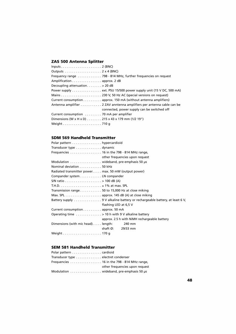
ZAS 500 Antenna SplitterInputs . . . . . . . . . . . . . . . . . . . . . . 2 (BNC)
Outputs . . . . . . . . . . . . . . . . . . . . 2 x 4 (BNC)
Frequency range . . . . . . . . . . . . . 798 - 814 MHz, further frequencies on request
Amplification . . . . . . . . . . . . . . . . approx. 2 dB
Decoupling attenuation. . . . . . . . > 20 dB
Power supply . . . . . . . . . . . . . . . . ext. PSU 15/500 power supply unit (15 V DC, 500 mA)
Mains . . . . . . . . . . . . . . . . . . . . . . 230 V, 50 Hz AC (special versions on request)
Current consumption . . . . . . . . . . approx. 150 mA (without antenna amplifiers)
Antenna amplifier . . . . . . . . . . . 2 ZAV anntenna amplifiers per antenna cable can be
connected, power supply can be switched off
Current consumption . . . . . . . . . 70 mA per amplifier
Dimensions (W x H x D) . . . . . . . . 215 x 43 x 179 mm (1/2 19")
Weight . . . . . . . . . . . . . . . . . . . . . 710 g
SDM 569 Handheld TransmitterPolar pattern . . . . . . . . . . . . . . . . hypercardioid
Transducer type . . . . . . . . . . . . . . dynamic
Frequencies . . . . . . . . . . . . . . . . . 16 in the 798 - 814 MHz range,
other frequencies upon request
Modulation . . . . . . . . . . . . . . . . . wideband, pre-emphasis 50 µs
Nominal deviation . . . . . . . . . . . . 50 kHz
Radiated transmitter power. . . . . max. 50 mW (output power)
Compander system. . . . . . . . . . . . LN compander
S/N ratio . . . . . . . . . . . . . . . . . . . . > 100 dB (A)
T.H.D. . . . . . . . . . . . . . . . . . . . . . . " 1% at max. SPL
Transmission range. . . . . . . . . . . . 50 to 15,000 Hz at close miking
Max. SPL . . . . . . . . . . . . . . . . . . . . approx. 145 dB (A) at close miking
Battery supply . . . . . . . . . . . . . . . 9 V alkaline battery or rechargeable battery, at least 6 V,
flashing LED at 6,5 V
Current consumption . . . . . . . . . . approx. 50 mA
Operating time . . . . . . . . . . . . . . > 10 h with 9 V alkaline battery
approx. 2.5 h with NiMH rechargeable battery
Dimensions (with mic head). . . . . length: 240 mm
shaft Ø: 29/33 mm
Weight . . . . . . . . . . . . . . . . . . . . . 170 g
SEM 581 Handheld TransmitterPolar pattern . . . . . . . . . . . . . . . . cardioid
Transducer type . . . . . . . . . . . . . . electret condenser
Frequencies . . . . . . . . . . . . . . . . . 16 in the 798 - 814 MHz range,
other frequencies upon request
Modulation . . . . . . . . . . . . . . . . . wideband, pre-emphasis 50 µs

Nominal deviation . . . . . . . . . . . . 50 kHz
Radiated transmitter power. . . . . max. 50 mW (output power)
Compander system. . . . . . . . . . . . LN compander
S/N ratio . . . . . . . . . . . . . . . . . . . . > 100 dB (A)
T.H.D. . . . . . . . . . . . . . . . . . . . . . . " 1% at max. SPL
Transmission range. . . . . . . . . . . . 70 to 18,000 Hz
Max. SPL . . . . . . . . . . . . . . . . . . . . approx. 145 dB (A) at close miking
Battery supply . . . . . . . . . . . . . . . 9 V alkaline battery or rechargeable battery, at least 6 V,
flashing LED at 6,5 V
Current consumption . . . . . . . . . . approx. 50 mA
Operating time . . . . . . . . . . . . . . > 10 h with 9 V alkaline battery
approx. 2.5 h with NiMH rechargeable battery
Dimensions (with mic head). . . . . length: 240 mm
shaft Ø: 29/33 mm
Weight . . . . . . . . . . . . . . . . . . . . . 170 g
TS 500 Beltpack TransmitterCarrier frequencies. . . . . . . . . . . . 16 frequencies switchable in the 798 - 814 MHz frequency
range, further frequencies upon request
Modulation . . . . . . . . . . . . . . . . . wideband, preemphasis 50 µs
Nominal deviation . . . . . . . . . . . . 50 kHz
Transmitter power . . . . . . . . . . . . approx. 50 mW (output power)
Compander system. . . . . . . . . . . . LN-compander
S/N ratio . . . . . . . . . . . . . . . . . . . . > 100 dB (A)
T.H.D. . . . . . . . . . . . . . . . . . . . . . . " 1% at max. SPL
Frequency response . . . . . . . . . . . 50 Hz to 18,000 Hz
Sensitivity . . . . . . . . . . . . . . . . . . . automatic switching
for instruments approx. 1200 mV / 300 mV
for microphones 200 mV / 50 mV
Power supply . . . . . . . . . . . . . . . . 9 V alkaline battery or NiMH rechargeable battery,
at least 6 V, flashing LED at 6.5 V
Current consumption . . . . . . . . . . 45 mA
Operating time . . . . . . . . . . . . . . with 9 V alkaline battery > 10 h
with NiMH rechargeable battery approx. 2.5 h
Dimensions (H x W x D) . . . . . . . . 80 x 60 x 21.5 mm
Weight . . . . . . . . . . . . . . . . . . . . . 80 g
Connection Lemo socket:
Pin 1 = 0 V
Pin 2 = stability voltage 6 V DC
Pin 3 = audio input with DC for electret condenser
microphones (2-pole connection)
Pin 4 = audio input, without DC for electret condenser
microphones (3-pole connection),
dynamic microphones, instruments
49
(Top view)
21
34

EC-DECLARATIONOF
CONFORMITY
Application ofCouncil directive: 89/336/EEC, 93/68/EEC
Electromagnetic Compatibility
99/5/EECR&TTE Directive
Standards to which Conformity is Declared: EN 60268 (former DIN IEC 268)
ETS 300 422ETS 300 445
Manufacturer's Name: beyerdynamic GmbH & Co.
Manufacturer's Address: Theresienstrasse 8, 74072 Heilbronn, Germany
Type of Equipment: Wireless Microphone System
Model Numbers: SDM 569, SEM 581, TS 500
I, the undersigned, as an employee of beyerdynamic, hereby declare thatthe equipment specified conforms to the above Directive and Standards.
Manufacturer’s Signature:
Date: 1. January, 2001
Full Name: Ulrich Roth
Position: R&D Manager

Garantie
In den Ländern der EU (EWR) bietet beyerdynamic neben den gesetzlichen Gewährleistungsansprüchen gegen den VerkäuferGarantie für die in der EU gekauften Geräte. Die Garantieleistung beinhaltet Material und Arbeit während der Garantiezeit, welchein den einzelnen Ländern der EU vom beyerdynamic-Vertriebspartner festgesetzt ist.In allen Ländern gelten neben den gesetzlichen Bestimmungen die von der beyerdynamic-Verkaufsstelle gewährtenGarantieleistungen. Die Garantie ist in diesem Fall nur im Verkaufsland gültig und beträgt in Deutschland 12 Monate. Die Garantieerlischt bei unsachgemäßen Eingriffen oder nicht fachmännisch durchgeführten Reparaturen.Eventuell mitgelieferte Batterien, sowie Teile, die beim Gebrauch einem natürlichen Verschleiß unterliegen, wie Anschlußkabel,Ohrmuschel, Kopfpolster etc. sind von der Garantie ausgeschlossen.
Wichtig: Die Rechnung gilt als Garantieschein.
Warranty
In the countries that are part of the EC (EEC) beyerdynamic supplies a warranty for the equipment purchased there. The warrantycovers labour and material during at least 12 months from the date of purchase. In all other respects the warranty is subject to thelaws of the corresponding country.In all other countries either the legal provisions or the warranty granted by the beyerdynamic dealer is applicable. In this case thewarranty is only valid within the country of sale.The warranty becomes null and void if the equipment has been tampered with or repaired by inexperienced persons.Batteries supplied and parts which are subject to normal wear and tear such as connecting cables, ear- and head-cushions are excluded from this warranty.
Important: The invoice is accepted as the guarantee.
Garantie
Dans les pays de la CE (CEE) beyerdynamic garantit les appareils qui y ont été achetés. La prestation de garantie comprend le matéri-al et la main-d’œuvre pendant au moins 12 mois à dater de l’achat. Par ailleurs, les prestations de garantie sont accordées selon lesprescriptions légales du pays concerné. Dans tous les autres pays, les dispositions légales ou les prestations de garantie du point de vente sont valable. Dans ce cas, la garan-tie n’est valable que dans le pays de vente. La garantie est caduque en cas d’interventions ou de réparations non conformes auxrègles de l’art.Les piles éventuellement livrées avec l’appareil sont excluses de la garantie. Il en est de même pour les pièces soumeses à une usurenaturelle.
Important: La facture d’achat fait office de garantie.
DEF 2/BA Opus 500 (09.01)/549.983/Hoh. Printed in Germany
Änderungen und Irrtümer vorbehalten
Subject to change without notice
Sous réserve de modifications
Germany
Theresienstr. 874072 HeilbronnTel. (0 71 31) 6 17-0Fax (0 71 31) [email protected]
United States
56 Central Ave.Farmingdale, NY 11735Tel. (631) 293-3200Fax (631) [email protected]
Great Britain
17 Albert DriveBurgess Hill RH15 9TNTel. (01444) 258 258Fax (01444) 258 [email protected]


![Tristeza , la - Opus 22 - piano - solo - seul - [Opus 22 -] · Tristeza , la - Opus 22 - piano - solo - seul - [Opus 22 -] Author: stumpf, werner - Arranger: STUMPF Werner - Publisher:](https://img.pdfslide.us/doc/110x75/5fdeb08016d6b213e84f7eba/tristeza-la-opus-22-piano-solo-seul-opus-22-tristeza-la-opus.jpg)


![Opus 144, Six Fairy Tales for Flute Solo [Opus 144]](https://img.pdfslide.us/doc/110x75/61e4550386b9437ad2408547/opus-144-six-fairy-tales-for-flute-solo-opus-144.jpg)