Embed Size (px)
Citation preview
Optoelectronics EE/OPE 451, OPT 444
Fall 2009 Section 1: T/Th 9:30- 10:55 PM
John D. Williams, Ph.D.
Department of Electrical and Computer Engineering
406 Optics Building - UAHuntsville, Huntsville, AL 35899
Ph. (256) 824-2898 email: [email protected]
Office Hours: Tues/Thurs 2-3PM
JDW, ECE Fall 2009
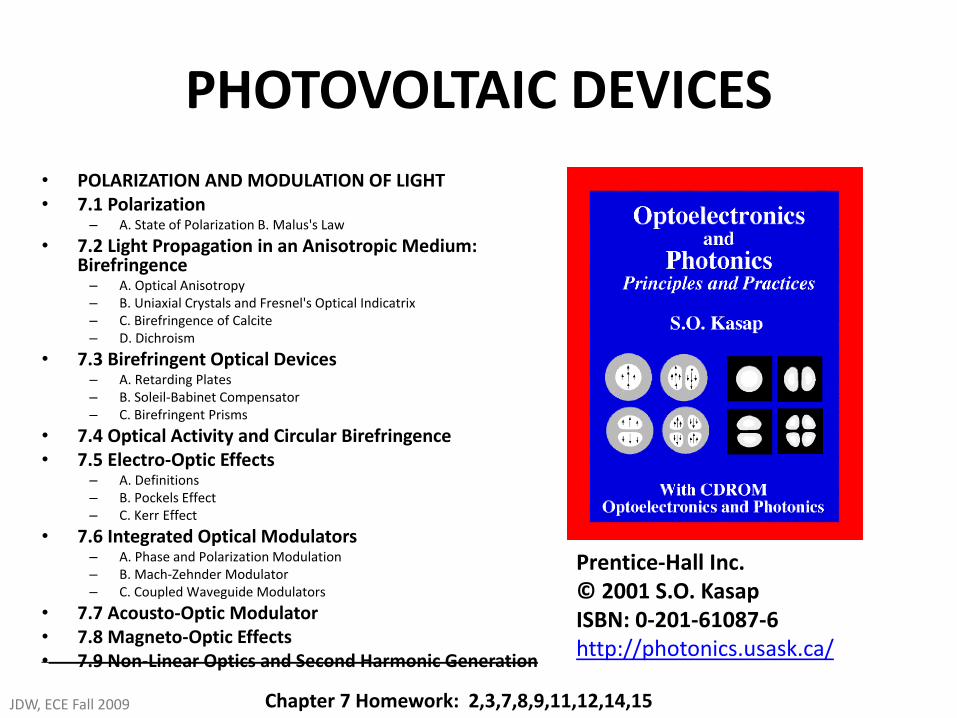
PHOTOVOLTAIC DEVICES
Prentice-Hall Inc. © 2001 S.O. Kasap ISBN: 0-201-61087-6 http://photonics.usask.ca/
• POLARIZATION AND MODULATION OF LIGHT • 7.1 Polarization
– A. State of Polarization B. Malus's Law
• 7.2 Light Propagation in an Anisotropic Medium: Birefringence – A. Optical Anisotropy – B. Uniaxial Crystals and Fresnel's Optical Indicatrix – C. Birefringence of Calcite – D. Dichroism
• 7.3 Birefringent Optical Devices – A. Retarding Plates – B. Soleil-Babinet Compensator – C. Birefringent Prisms
• 7.4 Optical Activity and Circular Birefringence • 7.5 Electro-Optic Effects
– A. Definitions – B. Pockels Effect – C. Kerr Effect
• 7.6 Integrated Optical Modulators – A. Phase and Polarization Modulation – B. Mach-Zehnder Modulator – C. Coupled Waveguide Modulators
• 7.7 Acousto-Optic Modulator • 7.8 Magneto-Optic Effects • 7.9 Non-Linear Optics and Second Harmonic Generation
JDW, ECE Fall 2009 Chapter 7 Homework: 2,3,7,8,9,11,12,14,15
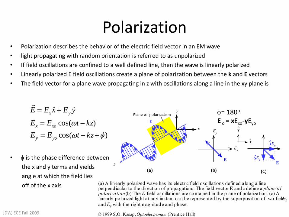
Polarization • Polarization describes the behavior of the electric field vector in an EM wave
• light propagating with random orientation is referred to as unpolarized
• If field oscillations are confined to a well defined line, then the wave is linearly polarized
• Linearly polarized E field oscillations create a plane of polarization between the k and E vectors
• The field vector for a plane wave propagating in z with oscillations along a line in the xy plane is
• is the phase difference between
the x and y terms and yields
angle at which the field lies
off of the x axis
x
y
z
Ey
Ex
yEy
^
xEx
^
(a) (b) (c)
E
Plane of polarization
x^
y^
E
(a) A linearly polarized wave has its electric field oscillations defined along a lineperpendicular to the direction of propagation, z. The field vector E and z define a plane o fpolariza tion. (b) The E-field os cillations are contained in the p lane of polarization. (c) Alinearly polarized light at any instant can be represented by the superposition of two fields Ex
and Ey with the right magnitude and phase.
E
© 1999 S.O. Kasap, Optoelectronics (Prentice Hall)
)cos(
)cos(
ˆˆ
kztEE
kztEE
yExEE
yoy
xox
yx
= 180o
E o = xExo-yEyo
JDW, ECE Fall 2009
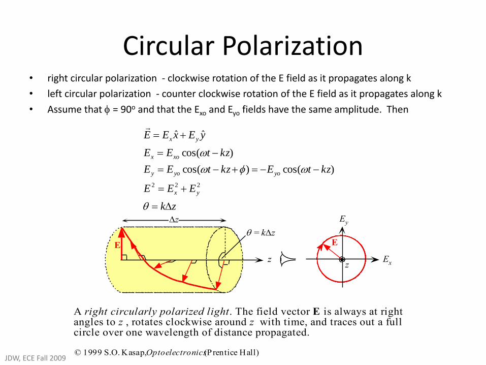
Circular Polarization • right circular polarization - clockwise rotation of the E field as it propagates along k
• left circular polarization - counter clockwise rotation of the E field as it propagates along k
• Assume that = 90o and that the Exo and Eyo fields have the same amplitude. Then
z
Ey
Ex
EE
= kz
z
z
A right circularly polarized light. The field vector E is always at rightangles to z , rotates clockwise around z with time, and traces out a fullcircle over one wavelength of distance propagated.
© 1999 S.O. Kasap, Optoelectronics (Prentice Hall)
zk
EEE
kztEkztEE
kztEE
yExEE
yx
yoyoy
xox
yx
222
)cos()cos(
)cos(
ˆˆ
JDW, ECE Fall 2009
Linear and Circular Polarization
E
y
x
Exo
= 0E
yo = 1
= 0
y
x
Exo
= 1E
yo = 1
= 0
y
x
Exo
= 1E
yo = 1
= /2
E
y
x
Exo
= 1E
yo = 1
= /2
(a) (b) (c) (d)
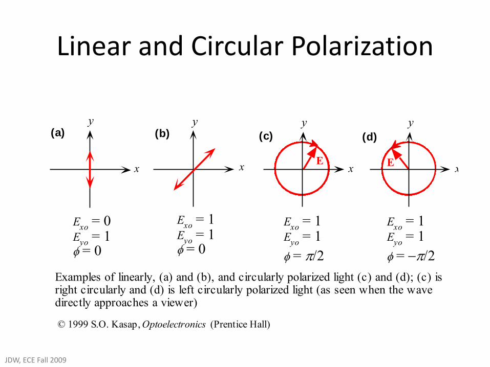
Examples of linearly, (a) and (b), and circularly polarized light (c) and (d); (c) isright circularly and (d) is left circularly polarized light (as seen when the wavedirectly approaches a viewer)
© 1999 S.O. Kasap, Optoelectronics (Prentice Hall)
JDW, ECE Fall 2009
Linear and Elliptical Polarization
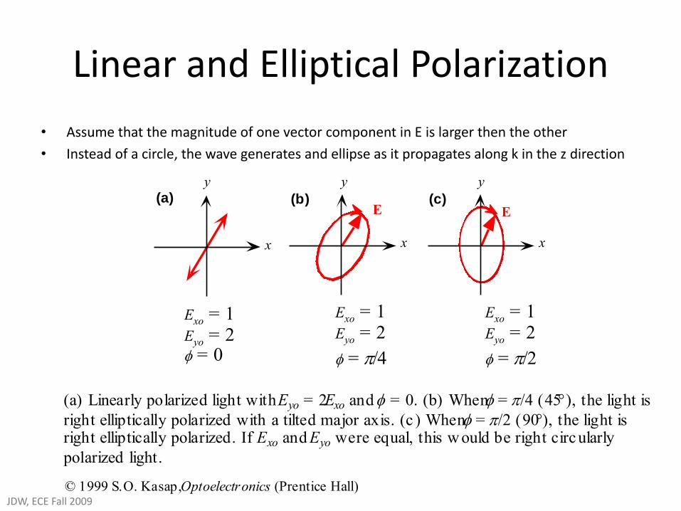
• Assume that the magnitude of one vector component in E is larger then the other
• Instead of a circle, the wave generates and ellipse as it propagates along k in the z direction
E
y
x
Exo = 1Eyo = 2 = 0
Exo = 1Eyo = 2
= /4
Exo = 1Eyo = 2
= /2
y
x
(a) (b)E
y
x
(c)
(a) Linearly polarized light with Eyo = 2Exo and = 0. (b) When = /4 (45), the light is
right elliptically polarized with a tilted major axis. (c ) When = /2 (90), the light isright elliptically polarized. If Exo and Eyo were equal, this w ould be right circularly
polarized light.
© 1999 S.O. Kasap, Optoelectronics (Prentice Hall)JDW, ECE Fall 2009
Example: Elliptical and Circular Polarization
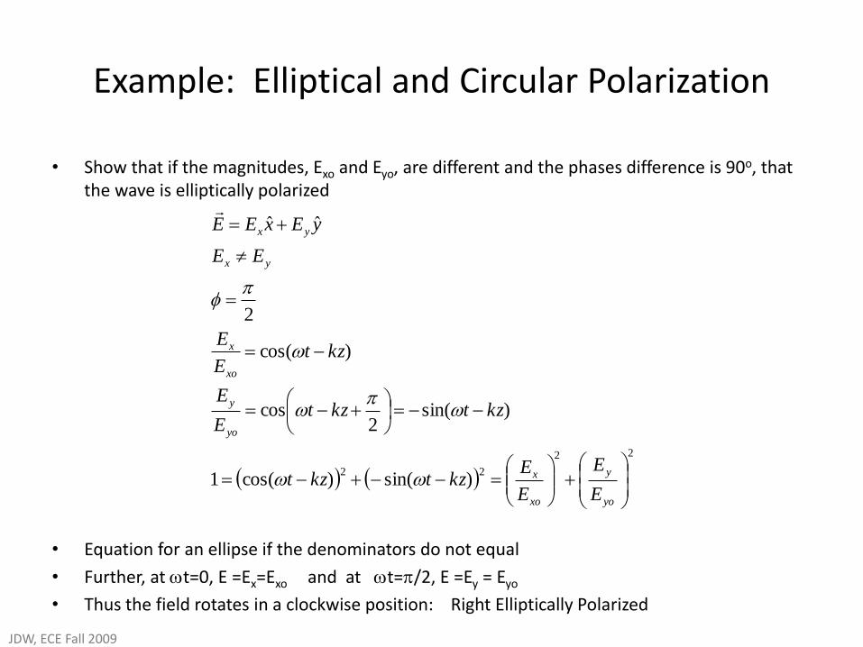
• Show that if the magnitudes, Exo and Eyo, are different and the phases difference is 90o, that the wave is elliptically polarized
• Equation for an ellipse if the denominators do not equal
• Further, at t=0, E =Ex=Exo and at t=/2, E =Ey = Eyo
• Thus the field rotates in a clockwise position: Right Elliptically Polarized
22
22)sin()cos(1
)sin(2
cos
)cos(
2
ˆˆ
yo
y
xo
x
yo
y
xo
x
yx
yx
E
E
E
Ekztkzt
kztkztE
E
kztE
E
EE
yExEE
JDW, ECE Fall 2009
Malus’s Law
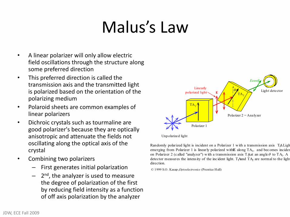
• A linear polarizer will only allow electric field oscillations through the structure along some preferred direction
• This preferred direction is called the transmission axis and the transmitted light is polarized based on the orientation of the polarizing medium
• Polaroid sheets are common examples of linear polarizers
• Dichroic crystals such as tourmaline are good polarizer's because they are optically anisotropic and attenuate the fields not oscillating along the optical axis of the crystal
• Combining two polarizers
– First generates initial polarization
– 2nd, the analyzer is used to measure the degree of polarization of the first by reducing field intensity as a function of off axis polarization by the analyzer
Polarizer 1
TA1
Polarizer 2 = Analyzer
TA2
Light detectorE
Ecos
Unpolarized light
Linearly
polarized light
Randomly polarized light is incident on a Polarizer 1 w ith a transmission axis TA1. Light
emerging from Polarizer 1 is linearly polarized with E along TA1, and becomes incident
on Polarizer 2 (called "analyzer") w ith a transmission axis TA2 at an angle to TA1. A
detector measures the intens ity of the inc ident light. TA1 and TA2 are normal to the light
direction.
© 1999 S.O. Kasap , Optoelectronics (Prentice Hall)
JDW, ECE Fall 2009
Optical Anisotropy • We know that electronic polarization in a medium
depends on crystal orientation
• Materials with isotropic crystal structures typically generate uniform polarization along all three principle axis and little or no off axis polarization terms
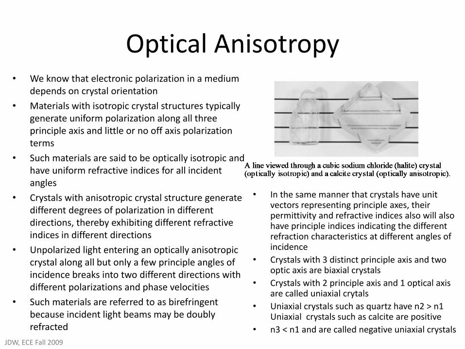
• Such materials are said to be optically isotropic and have uniform refractive indices for all incident angles
• Crystals with anisotropic crystal structure generate different degrees of polarization in different directions, thereby exhibiting different refractive indices in different directions
• Unpolarized light entering an optically anisotropic crystal along all but only a few principle angles of incidence breaks into two different directions with different polarizations and phase velocities
• Such materials are referred to as birefringent because incident light beams may be doubly refracted
• In the same manner that crystals have unit vectors representing principle axes, their permittivity and refractive indices also will also have principle indices indicating the different refraction characteristics at different angles of incidence
• Crystals with 3 distinct principle axis and two optic axis are biaxial crystals
• Crystals with 2 principle axis and 1 optical axis are called uniaxial crytals
• Uniaxial crystals such as quartz have n2 > n1 Uniaxial crystals such as calcite are positive
• n3 < n1 and are called negative uniaxial crystals
JDW, ECE Fall 2009
Uniaxial Crystals and Fresnel’s Optical Indicatrix
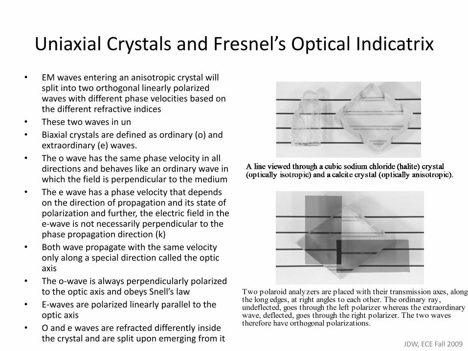
• EM waves entering an anisotropic crystal will split into two orthogonal linearly polarized waves with different phase velocities based on the different refractive indices
• These two waves in un
• Biaxial crystals are defined as ordinary (o) and extraordinary (e) waves.
• The o wave has the same phase velocity in all directions and behaves like an ordinary wave in which the field is perpendicular to the medium
• The e wave has a phase velocity that depends on the direction of propagation and its state of polarization and further, the electric field in the e-wave is not necessarily perpendicular to the phase propagation direction (k)
• Both wave propagate with the same velocity only along a special direction called the optic axis
• The o-wave is always perpendicularly polarized to the optic axis and obeys Snell’s law
• E-waves are polarized linearly parallel to the optic axis
• O and e waves are refracted differently inside the crystal and are split upon emerging from it
Two polaroid analyzers are placed with their transmission axes, alongthe long edges, at right angles to each other. The ordinary ray,undeflected, goes through the left polarizer whereas the extraordinarywave, deflected, goes through the right polarizer. The two wavestherefore have orthogonal polarizations.
JDW, ECE Fall 2009
Uniaxial Crystals and Fresnel’s Optical Indicatrix
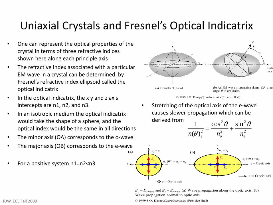
• One can represent the optical properties of the crystal in terms of three refractive indices shown here along each principle axis
• The refractive index associated with a particular EM wave in a crystal can be determined by Fresnel’s refractive index ellipsoid called the optical indicatrix
• In the optical indicatrix, the x y and z axis intercepts are n1, n2, and n3.
• In an isotropic medium the optical indicatrix would take the shape of a sphere, and the optical index would be the same in all directions
• The minor axis (OA) corresponds to the o-wave
• The major axis (OB) corresponds to the e-wave
• For a positive system n1=n2<n3
n2
Op tic
ax is
n1
x
y
zn3 O
B
A
P
B
A
z
k
O
(b) An EM wave propagating along OP at anangle to opt ic axis.
(a) Fresnel's ellipsoid
© 1999 S.O. Kasap, Optoelectronics (Prentice Hall)
no = n1
x
yz = Optic axis
ne (90) = n3
z = Optic axis
(b)
Eo
Ee
x
z
Eo
Ee
z = Optic axis
ne (0) = n
2 = n
1
no = n1
y
(a)
Eo = Eo-wave and Ee = Ee-wave (a) Wave propagation along the optic axis. (b)
Wave propagation normal to optic axis
© 1999 S.O. Kasap, Optoelectronics (Prentice Hall)
• Stretching of the optical axis of the e-wave causes slower propagation which can be derived from
2
2
2
2
2
sincos
)(
1
eoe nnn
JDW, ECE Fall 2009
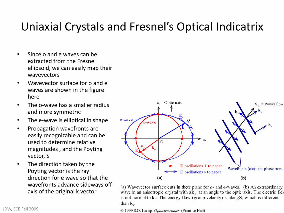
• Since o and e waves can be extracted from the Fresnel ellipsoid, we can easily map their wavevectors
• Wavevector surface for o and e waves are shown in the figure here
• The o-wave has a smaller radius and more symmetric
• The e-wave is elliptical in shape
• Propagation wavefronts are easily recognizable and can be used to determine relative magnitudes , and the Poyting vector, S
• The direction taken by the Poyting vector is the ray direction for e wave so that the wavefronts advance sideways off axis of the original k vector
(b)
Optic axiskz
o-wavee-wave
Ee
Okx
(a)
E oscillations to paperWavefronts (constant phase fronts)
Se = Power flow
Q
P ko
ke
ke
ke
Ee
Eo
(a) Wavevector surface cuts in the xz plane for o- and e-waves. (b) An extraordinarywave in an anisotropic crystal with a ke at an angle to the optic axis. The electric field
is not normal to ke. The energy flow (group velocity) is along Se which is different
than ke.
© 1999 S.O. Kasap, Optoelectronics (Prentice Hall)
E oscillations // to paper
Uniaxial Crystals and Fresnel’s Optical Indicatrix
JDW, ECE Fall 2009
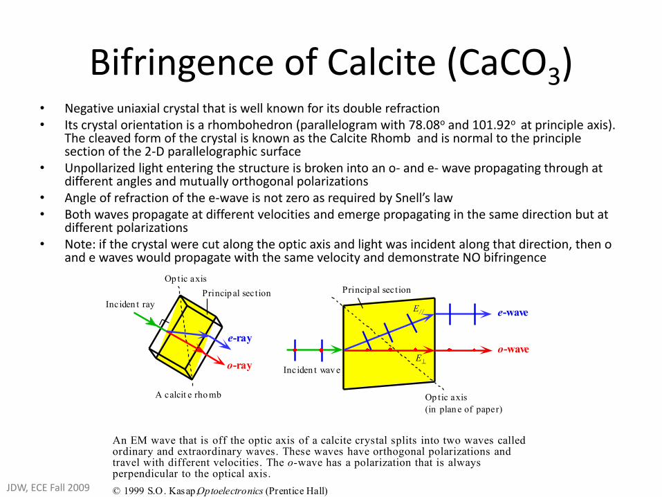
Bifringence of Calcite (CaCO3) • Negative uniaxial crystal that is well known for its double refraction • Its crystal orientation is a rhombohedron (parallelogram with 78.08o and 101.92o at principle axis).
The cleaved form of the crystal is known as the Calcite Rhomb and is normal to the principle section of the 2-D parallelographic surface
• Unpollarized light entering the structure is broken into an o- and e- wave propagating through at different angles and mutually orthogonal polarizations
• Angle of refraction of the e-wave is not zero as required by Snell’s law • Both waves propagate at different velocities and emerge propagating in the same direction but at
different polarizations • Note: if the crystal were cut along the optic axis and light was incident along that direction, then o
and e waves would propagate with the same velocity and demonstrate NO bifringence
e-wave
o-wave
Op tic axis
(in plan e of paper)
Op tic axis
Princip al section
e-ray
o-ray
Princip al section
A calcit e rho mb
E
E/ /Inciden t ray
Inciden t wav e
An EM wave that is off the optic axis of a calcite crystal splits into two waves calledordinary and extraordinary waves. These waves have orthogonal polarizations andtravel with different velocities. The o-wave has a polarization that is alwaysperpendicular to the optical axis.
© 1999 S.O. Kasap, Optoelectronics (Prentice Hall)JDW, ECE Fall 2009
Dichroism
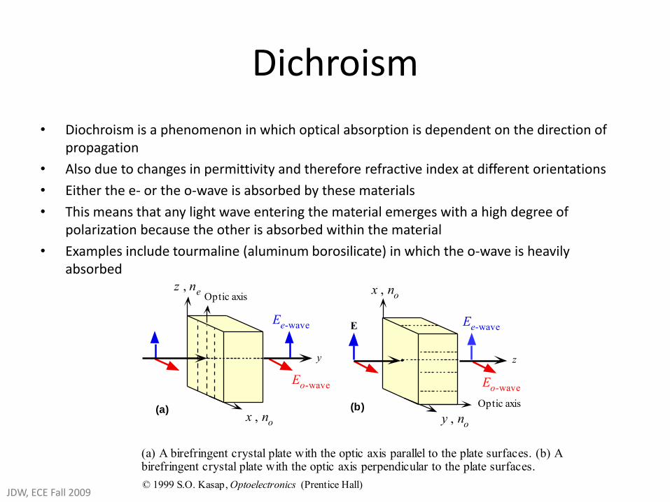
• Diochroism is a phenomenon in which optical absorption is dependent on the direction of propagation
• Also due to changes in permittivity and therefore refractive index at different orientations
• Either the e- or the o-wave is absorbed by these materials
• This means that any light wave entering the material emerges with a high degree of polarization because the other is absorbed within the material
• Examples include tourmaline (aluminum borosilicate) in which the o-wave is heavily absorbed
Optic axis
x , no
y
Ee-wave
Eo-wave
z , ne
Optic axis
y , no
E
z
Ee-wave
Eo-wave
x , no
(a) (b)
(a) A birefringent crystal plate with the optic axis parallel to the plate surfaces. (b) Abirefringent crystal plate with the optic axis perpendicular to the plate surfaces.
© 1999 S.O. Kasap, Optoelectronics (Prentice Hall)JDW, ECE Fall 2009
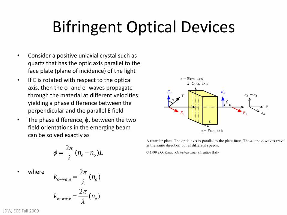
Bifringent Optical Devices
• Consider a positive uniaxial crystal such as quartz that has the optic axis parallel to the face plate (plane of incidence) of the light
• If E is rotated with respect to the optical axis, then the o- and e- waves propagate through the material at different velocities yielding a phase difference between the perpendicular and the parallel E field
• The phase difference, , between the two field orientations in the emerging beam can be solved exactly as
• where
x = Fast axis
z = Slow axis
E//
E
E//
E
E
L
y
no
ne = n3
Optic axis
L
y
no
ne = n3
A retarder plate. The optic axis is parallel to the plate face. The o- and e-waves travelin the same direction but at different speeds.
© 1999 S.O. Kasap, Optoelectronics (Prentice Hall)Lnn oe )(2
)(2
)(2
ewavee
owaveo
nk
nk
JDW, ECE Fall 2009
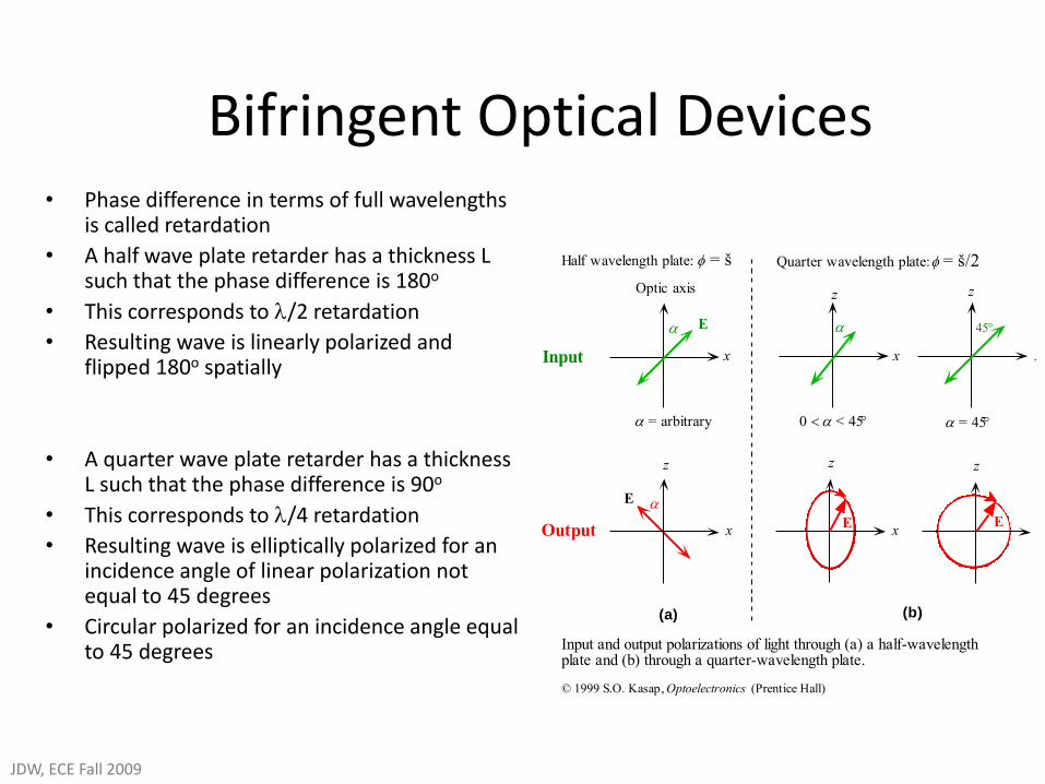
• Phase difference in terms of full wavelengths is called retardation
• A half wave plate retarder has a thickness L such that the phase difference is 180o
• This corresponds to /2 retardation
• Resulting wave is linearly polarized and flipped 180o spatially
• A quarter wave plate retarder has a thickness L such that the phase difference is 90o
• This corresponds to /4 retardation
• Resulting wave is elliptically polarized for an incidence angle of linear polarization not equal to 45 degrees
• Circular polarized for an incidence angle equal to 45 degrees
x
= arbitrary
(b)
Input
z
xE
z
x
(a)
Output
Optic axis
Half wavelength plate: = š Quarter wavelength plate: = š/2
x
< 45
E
z
x
E
E
x
z z
= 45
45
Input and output polarizations of light through (a) a half-wavelengthplate and (b) through a quarter-wavelength plate.
© 1999 S.O. Kasap, Optoelectronics (Prentice Hall)
Bifringent Optical Devices
JDW, ECE Fall 2009
Soleil-Babinet Compensator
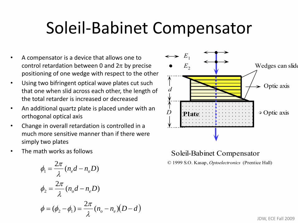
• A compensator is a device that allows one to control retardation between 0 and 2 by precise positioning of one wedge with respect to the other
• Using two bifringent optical wave plates cut such that one when slid across each other, the length of the total retarder is increased or decreased
• An additional quartz plate is placed under with an orthogonal optical axis
• Change in overall retardation is controlled in a much more sensitive manner than if there were simply two plates
• The math works as follows
Optic axis
Optic axisd
D
Wedges can slide
Plate
E1
E2
Soleil-Babinet Compensator
© 1999 S.O. Kasap, Optoelectronics (Prentice Hall)
dDnn
Dndn
Dndn
eo
eo
oe
)(2
)(
)(2
)(2
12
2
1
JDW, ECE Fall 2009
WollastonBifringent Prisms
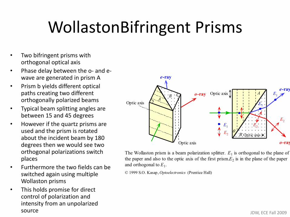
• Two bifringent prisms with orthogonal optical axis
• Phase delay between the o- and e- wave are generated in prism A
• Prism b yields different optical paths creating two different orthogonally polarized beams
• Typical beam splitting angles are between 15 and 45 degrees
• However if the quartz prisms are used and the prism is rotated about the incident beam by 180 degrees then we would see two orthogonal polarizations switch places
• Furthermore the two fields can be switched again using multiple Wollaston prisms
• This holds promise for direct control of polarization and intensity from an unpolarized source
Optic axis
e-ray
o-rayA
B
Optic axis
e-ray
o-ray
Optic axis A
B Optic axis
E1
E2
E1
E1
E2
E2
The Wollaston prism is a beam polarization splitter. E1 is orthogonal to the plane of
the paper and also to the optic axis of the first prism. E2 is in the plane of the paper
and orthogonal to E1.
© 1999 S.O. Kasap, Optoelectronics (Prentice Hall)
JDW, ECE Fall 2009
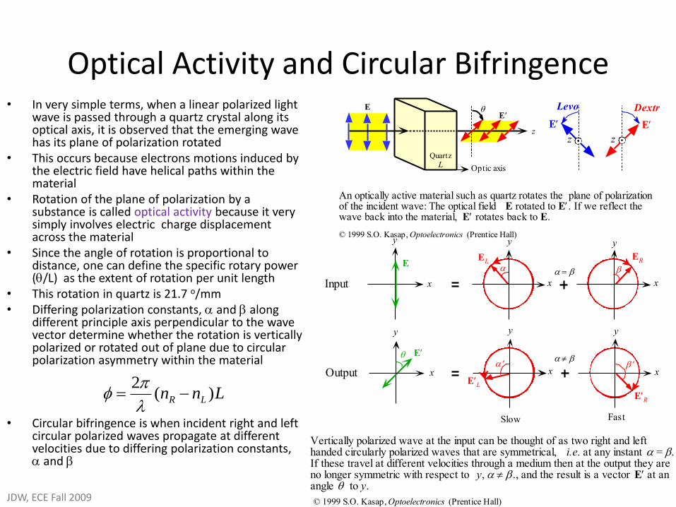
Optical Activity and Circular Bifringence • In very simple terms, when a linear polarized light
wave is passed through a quartz crystal along its optical axis, it is observed that the emerging wave has its plane of polarization rotated
• This occurs because electrons motions induced by the electric field have helical paths within the material
• Rotation of the plane of polarization by a substance is called optical activity because it very simply involves electric charge displacement across the material
• Since the angle of rotation is proportional to distance, one can define the specific rotary power (/L) as the extent of rotation per unit length
• This rotation in quartz is 21.7 o/mm • Differing polarization constants, and along
different principle axis perpendicular to the wave vector determine whether the rotation is vertically polarized or rotated out of plane due to circular polarization asymmetry within the material
• Circular bifringence is when incident right and left circular polarized waves propagate at different velocities due to differing polarization constants, and
E
Optic axis
E
z
LQuartz
z
Dextro
z
Levo
E E
An optically active material such as quartz rotates the plane of polarizationof the incident wave: The optical field E rotated to E. If we reflect thewave back into the material, E rotates back to E.
© 1999 S.O. Kasap, Optoelectronics (Prentice Hall)
xInput
y
x
y
EL
y
x
ER
xOutput
y
x
y
EL
y
x
ER
E
E
Slow Fast
Vertically polarized wave at the input can be thought of as two right and lefthanded circularly polarized waves that are symmetrical, i.e. at any instant = .If these travel at different velocities through a medium then at the output they areno longer symmetric with respect to y, ., and the result is a vector E at anangle to y.
© 1999 S.O. Kasap, Optoelectronics (Prentice Hall)
Lnn LR )(2
JDW, ECE Fall 2009
Electro-Optics and Frequency Dependent Permittivity
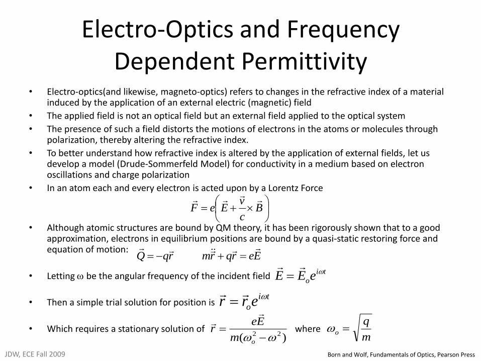
• Electro-optics(and likewise, magneto-optics) refers to changes in the refractive index of a material induced by the application of an external electric (magnetic) field
• The applied field is not an optical field but an external field applied to the optical system
• The presence of such a field distorts the motions of electrons in the atoms or molecules through polarization, thereby altering the refractive index.
• To better understand how refractive index is altered by the application of external fields, let us develop a model (Drude-Sommerfeld Model) for conductivity in a medium based on electron oscillations and charge polarization
• In an atom each and every electron is acted upon by a Lorentz Force
• Although atomic structures are bound by QM theory, it has been rigorously shown that to a good approximation, electrons in equilibrium positions are bound by a quasi-static restoring force and equation of motion:
• Letting be the angular frequency of the incident field
• Then a simple trial solution for position is
• Which requires a stationary solution of where
B
c
vEeF
ti
oeEE
)( 22
om
Eer
rqQ
Eerqrm
ti
oerr
m
qo
JDW, ECE Fall 2009 Born and Wolf, Fundamentals of Optics, Pearson Press
Frequency Dependent Permittivity
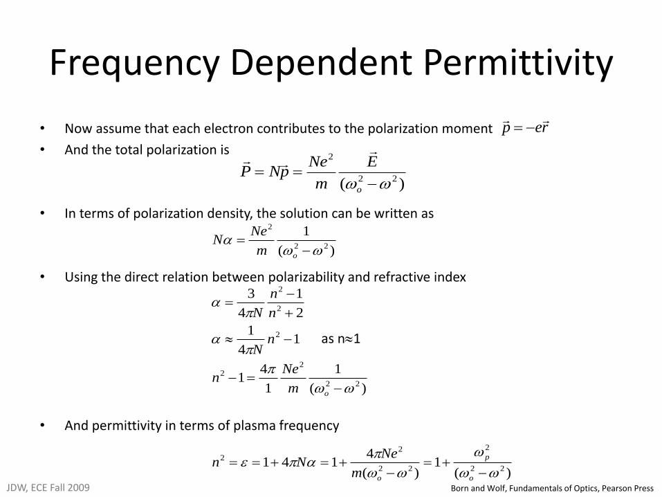
• Now assume that each electron contributes to the polarization moment
• And the total polarization is
• In terms of polarization density, the solution can be written as
• Using the direct relation between polarizability and refractive index
• And permittivity in terms of plasma frequency
)( 22
2
o
E
m
NepNP
rep
)(1
)(
4141
)(
1
1
41
14
1
2
1
4
3
)(
1
22
2
22
22
22
22
2
2
2
22
2
o
p
o
o
o
m
NeNn
m
Nen
nN
n
n
N
m
NeN
as n1
JDW, ECE Fall 2009 Born and Wolf, Fundamentals of Optics, Pearson Press
Frequency Dependent Anisotropic Permittivity
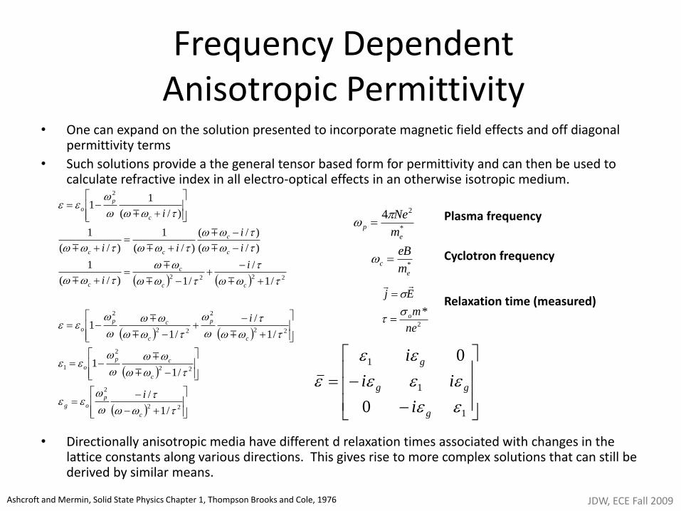
• One can expand on the solution presented to incorporate magnetic field effects and off diagonal permittivity terms
• Such solutions provide a the general tensor based form for permittivity and can then be used to calculate refractive index in all electro-optical effects in an otherwise isotropic medium.
• Directionally anisotropic media have different d relaxation times associated with changes in the lattice constants along various directions. This gives rise to more complex solutions that can still be derived by similar means.
*
24
e
pm
Ne
1
1
1
0
0
g
gg
g
i
ii
i
Plasma frequency
Cyclotron frequency
22
2
22
2
1
22
2
22
2
2222
2
/1
/
/11
/1
/
/11
/1
/
/1)/(
1
)/(
)/(
)/(
1
)/(
1
)/(
11
c
p
og
c
cp
o
c
p
c
cp
o
cc
c
c
c
c
cc
c
p
o
i
i
i
i
i
i
ii
i
Relaxation time (measured)
2
*
ne
m
Ej
o
*
e
cm
eB
JDW, ECE Fall 2009 Ashcroft and Mermin, Solid State Physics Chapter 1, Thompson Brooks and Cole, 1976
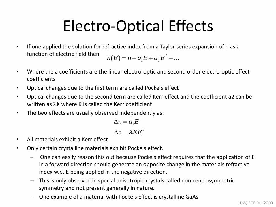
Electro-Optical Effects • If one applied the solution for refractive index from a Taylor series expansion of n as a
function of electric field then
• Where the a coefficients are the linear electro-optic and second order electro-optic effect coefficients
• Optical changes due to the first term are called Pockels effect
• Optical changes due to the second term are called Kerr effect and the coefficient a2 can be written as K where K is called the Kerr coefficient
• The two effects are usually observed independently as:
• All materials exhibit a Kerr effect
• Only certain crystalline materials exhibit Pockels effect.
– One can easily reason this out because Pockels effect requires that the application of E in a forward direction should generate an opposite change in the materials refractive index w.r.t E being applied in the negative direction.
– This is only observed in special anisotropic crystals called non centrosymmetric symmetry and not present generally in nature.
– One example of a material with Pockels Effect is crystalline GaAs
...)( 2
21 EaEanEn
2
1
KEn
Ean
JDW, ECE Fall 2009
Pockels Effect
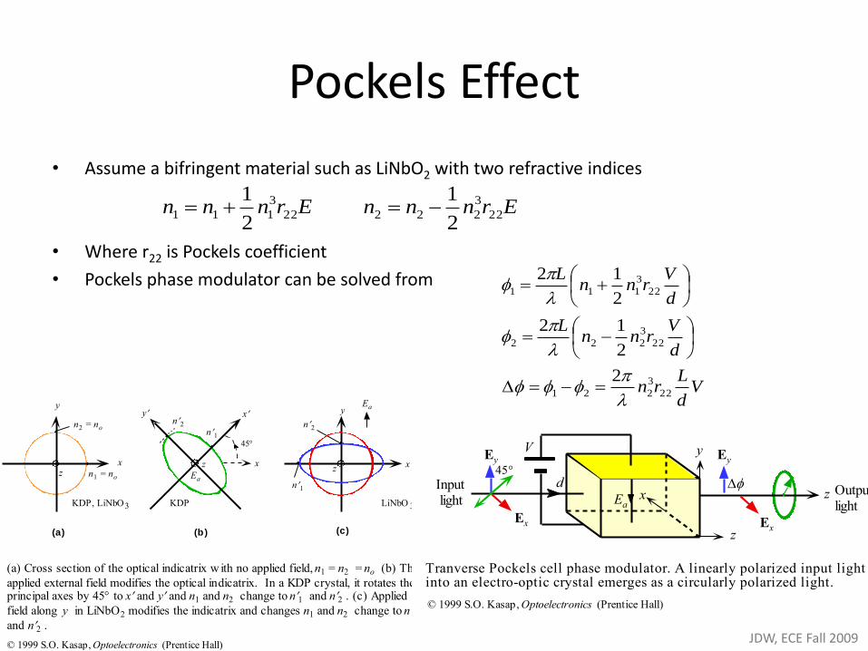
• Assume a bifringent material such as LiNbO2 with two refractive indices
• Where r22 is Pockels coefficient
• Pockels phase modulator can be solved from
xz Ea
n1 = no
y
(a)
xn2 = no
n1
n2
z
(b)
x
45
(c)
xz
KDP, LiNbO3 KDP LiNbO 3
n1
n2
y Eay
(a) Cross section of the optical indicatrix w ith no applied field, n1 = n2 = no (b) The
applied external field modifies the optical indicatrix. In a KDP crystal, it rotates theprincipal axes by 45 to x and y and n1 and n2 change to n1 and n2 . (c) Applied
field along y in LiNbO2 modifies the indicatrix and changes n1 and n2 change to n1and n2 .
© 1999 S.O. Kasap, Optoelectronics (Prentice Hall)
Ernnn 22
3
1112
1 Ernnn 22
3
2222
1
Outputlight
z
x
Ex
d
Ey
V
z
Ex
Eyy
Inputlight Ea
Tranverse Pockels cell phase modulator. A linearly polarized input lightinto an electro-optic crystal emerges as a circularly polarized light.
© 1999 S.O. Kasap, Optoelectronics (Prentice Hall)
Vd
Lrn
d
Vrnn
L
d
Vrnn
L
22
3
221
22
3
222
22
3
111
2
2
12
2
12
JDW, ECE Fall 2009
V(t)
Ea
Cross-section
LiNbO3
d
Thin buffer layerCopl anar strip electrod es
EO S ubstrate
zy
x
Polarized
input
light
Wav eguideLiNbO3
L
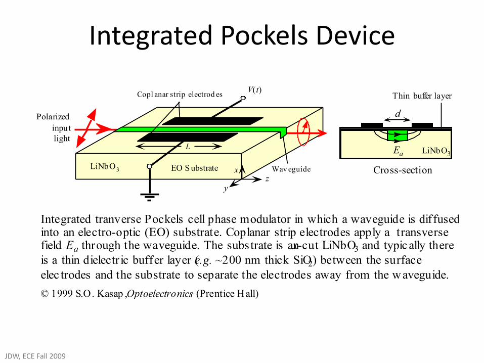
Integrated tranverse Pockels cell phase modulator in which a waveguide is diffusedinto an electro-optic (EO) substrate. Coplanar strip electrodes apply a transversefield Ea through the waveguide. The subs trate is an x-cut LiNbO3 and typically there
is a thin dielectric buffer layer (e.g. ~200 nm thick SiO2) between the surface
elec trodes and the substrate to separate the electrodes away from the w aveguide.
© 1999 S.O. Kasap , Optoelectronics (Prentice Hall)
Integrated Pockels Device
JDW, ECE Fall 2009
V(t)
LiNbO3 EO Substrate
A
BIn
OutC
DA
B
Waveguide
Electrode
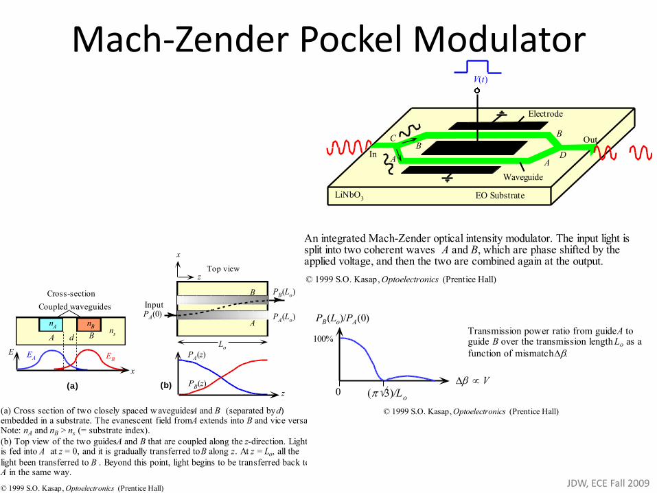
An integrated Mach-Zender optical intensity modulator. The input light issplit into two coherent waves A and B, which are phase shifted by theapplied voltage, and then the two are combined again at the output.
© 1999 S.O. Kasap, Optoelectronics (Prentice Hall)
Cross-section
Coupled waveguides
B
E
x
EA EB
d
nBnA
Ans
A
B
Top view
Lo
Input
PA(Lo)PA(0)
z
PB(Lo)
z
PA(z)
PB(z)(a) (b)
x
(a) Cross section of two closely spaced w aveguides A and B (separated by d)embedded in a substrate. The evanescent field from A extends into B and vice versa.Note: nA and nB > ns (= substrate index).
(b) Top view of the two guides A and B that are coupled along the z-direction. Lightis fed into A at z = 0, and it is gradually transferred to B along z. At z = Lo, all the
light been transferred to B . Beyond this point, light begins to be transferred back toA in the same way.
© 1999 S.O. Kasap, Optoelectronics (Prentice Hall)
Mach-Zender Pockel Modulator
V
PB(Lo)/PA(0)
100%
3)/Lo0
Transmission power ratio from guide A toguide B over the transmission length Lo as a
function of mismatch
© 1999 S.O. Kasap, Optoelectronics (Prentice Hall)
JDW, ECE Fall 2009
V(t)
LiNbO3
In
Electrode
Waveguides
Fibers
Ea
Cross-section
LiNbO3
V(t)
Coupled waveguides
A B
dA B
Lo
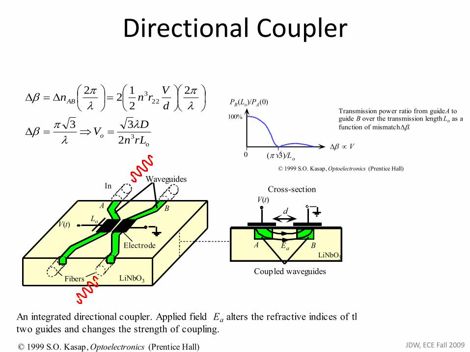
An integrated directional coupler. Applied field Ea alters the refractive indices of the
two guides and changes the strength of coupling.
© 1999 S.O. Kasap, Optoelectronics (Prentice Hall)
V
PB(Lo)/PA(0)
100%
3)/Lo0
Transmission power ratio from guide A toguide B over the transmission length Lo as a
function of mismatch
© 1999 S.O. Kasap, Optoelectronics (Prentice Hall)
o
o
AB
rLn
DV
d
Vrnn
3
22
3
2
33
2
2
12
2
Directional Coupler
JDW, ECE Fall 2009
Pockels Polarization Modulator
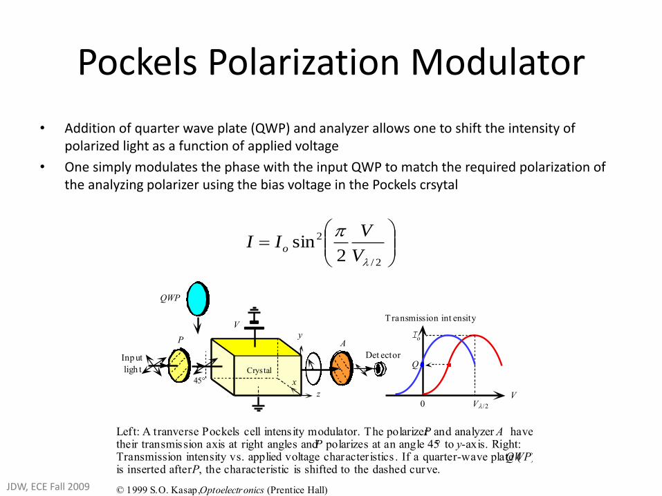
• Addition of quarter wave plate (QWP) and analyzer allows one to shift the intensity of polarized light as a function of applied voltage
• One simply modulates the phase with the input QWP to match the required polarization of the analyzing polarizer using the bias voltage in the Pockels crsytal
Transmission int ensity
V
Io
Q
0 V
V
Inp ut
ligh t
P A
Det ector
Crystal
z
x
y
QWP
Left: A tranverse Pockels cell intens ity modulator. The polarizer P and analyzer A havetheir transmission axis at right angles and P polarizes at an angle 45 to y-axis. Right:Transmission intensity vs. applied voltage characteristics . If a quarter-wave plate (QWP)is inserted after P, the characteristic is shifted to the dashed curve.
© 1999 S.O. Kasap, Optoelectronics (Prentice Hall)
2/
2
2sin
V
VII o
JDW, ECE Fall 2009
Kerr Effect
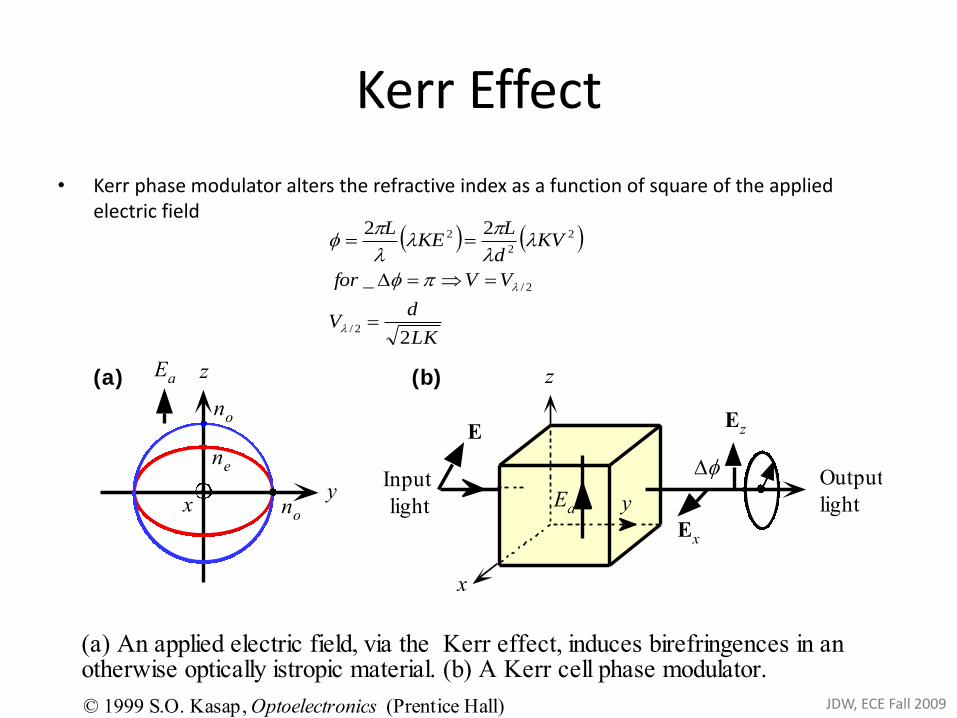
• Kerr phase modulator alters the refractive index as a function of square of the applied electric field
y
z
x no
no
ne
Ea z
x
yEa
Output
light
Ez
Input
light
Ex
E
(a) (b)
(a) An applied electric field, via the Kerr effect, induces birefringences in anotherwise optically istropic material. (b) A Kerr cell phase modulator.
© 1999 S.O. Kasap, Optoelectronics (Prentice Hall)
LK
dV
VVfor
KVd
LKE
L
2
_
22
2/
2/
2
2
2
JDW, ECE Fall 2009
Acousto-Optical Effect
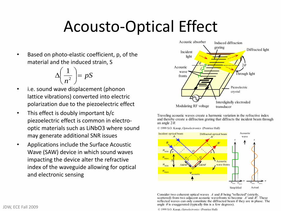
• Based on photo-elastic coefficient, p, of the material and the induced strain, S
• i.e. sound wave displacement (phonon lattice vibrations) converted into electric polarization due to the piezoelectric effect
• This effect is doubly important b/c piezoelectric effect is common in electro-optic materials such as LiNbO3 where sound may generate additional SNR issues
• Applications include the Surface Acoustic Wave (SAW) device in which sound waves impacting the device alter the refractive index of the waveguide allowing for optical and electronic sensing
pSn
2
1
Interdigitally electroded
transducerModulating RF voltage
Piezoelectric
crystal
Acoustic
wavefronts
Induced diffraction
grating
Incident
light
Diffracted light
Through light
Acoustic absorber
Traveling acoustic waves create a harmonic variation in the refractive indexand thereby create a diffraction grating that diffracts the incident beam throughan angle 2.
© 1999 S.O. Kasap, Optoelectronics (Prentice Hall)
A
B
Incident optical beam Diffracted optical beam
O
O'
P Q
B'
A'
sin sin
Acoustic
wave fronts
nmax
nmax
nmin
nmin
nmin n
ma x
x
nmin
nma x
x
nn
Simplified Actual
Acoustic
wave
vacoustic
Consider two coherent optical waves A and B being "reflected" (strictly,scattered) from two adjacent acoustic wavefronts to become A' and B'. Thesereflected waves can only constitute the diffracted beam if they are in phase. Theangle is exaggerated (typically this is a few degrees).
© 1999 S.O. Kasap, Optoelectronics (Prentice Hall)JDW, ECE Fall 2009
Magneto-Optical Effects
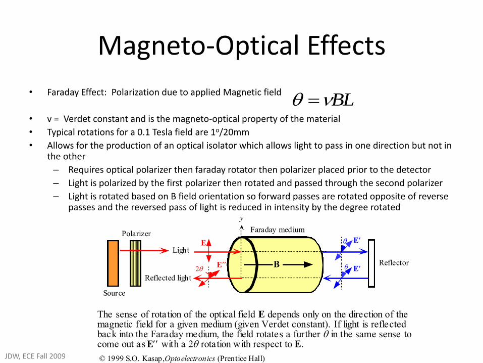
• Faraday Effect: Polarization due to applied Magnetic field
• v = Verdet constant and is the magneto-optical property of the material
• Typical rotations for a 0.1 Tesla field are 1o/20mm
• Allows for the production of an optical isolator which allows light to pass in one direction but not in the other
– Requires optical polarizer then faraday rotator then polarizer placed prior to the detector
– Light is polarized by the first polarizer then rotated and passed through the second polarizer
– Light is rotated based on B field orientation so forward passes are rotated opposite of reverse passes and the reversed pass of light is reduced in intensity by the degree rotated
E E
E E
Light
Reflected light
Reflector
Faraday medium
y
Polarizer
Source
The sense of rotation of the optical field E depends only on the direction of themagnetic field for a given medium (given Verdet constant). If light is reflectedback into the Faraday medium, the field rotates a further in the same sense tocome out as E with a 2 rotation with respect to E.
© 1999 S.O. Kasap, Optoelectronics (Prentice Hall)
B
BL
JDW, ECE Fall 2009