Embed Size (px)
Citation preview
Keywords: Comminution, Semi-Autogenous Grinding Mill (SAG Mill), Liner, Impact, Hertz
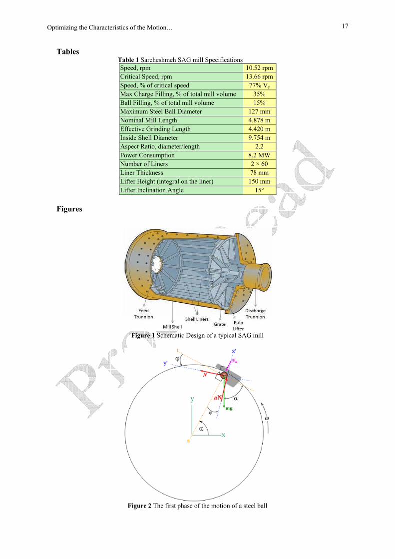
Contact Law. 1- Introduction Tumbling mills, which are a critical part of all mining operations and have been used for over 100 years to transform masses of ores to usable-size particles, consist of a cylindrical chamber filled with balls and/or rocks rotating about their longitudinal axes, as shown in Figure 1.
Autogenous grinding (AG) is the action of rocks grinding upon themselves. Grinding in AG mills is frequently assisted by steel balls, in which case it is called a Semi-Autogenous Grinding (SAG) mill. Semi-Autogenous Grinding mills came into operation in the mid 1970s [1].
1 Corresponding author, Faculty of Mechanical Engineering, Khajeh Nasir-Addin Toosi University of Technology, Email :[email protected] 2 Mechanical Engineering Department,Shahid-Bahonar University of Kerman Email : Fooladi@mail. uk.ac.ir
S. Ebrahimi-Nejad Rafsanjani 1 PhD Candidate
M. Fooladi-Mahani 2
Assistant Professor
Optimizing the Characteristics of the Motion of Steel Balls and their Impact on Shell Liners in SAG Mills The equations governing the motion of steel balls and their impact onto shell liners in industrial Semi-Autogenous Grinding (SAG) mills are derived in full details by the authors and are used in order to determine the effective design variables for optimizing the working conditions of the mill and to avoid severe impacts which lead to the breakage of SAG mill shell liners. These design variables are the lifter height H, the working coefficient of friction µ, lifter face inclination angle φ, steel ball size rB, mill rotational velocity ω, and mill size R. In order to optimize the operating conditions and avoid severe impacts to its shell liners, the effect of these parameters need to be studied. The effect of lifter height (H) and the coefficient of friction (µ) on some of the main impact characteristics are simultaneously investigated for a SAG mill in Sarcheshmeh Copper Complex. It was shown that as the lifter height or the coefficient of friction increases, the impact position tends to move upward, but the maximum impact force and the absolute value of the maximum principal stress decreases, reducing the impact severity.
Iranian Journal of Mechanical Engineering Vol. 10, No. 1, March 2009 6
Breakage in tumbling mills is grouped into impact breakage, abrasion breakage and attrition breakage [1]. However, Grant and Kalman [2] showed that the main mechanism controlling the grinding process in SAG mills is impact.
Comminution is the most energy-intensive part of the mineral recovery process [3]. However, it is believed that less than 5% of the energy supplied to comminution processes is used for particle breakage [4]; the rest is wasted through extra motions of the mill contents and collisions of the balls to the liners which not only waste energy but also damage the liners. SAG mills are lined with liners (lifters) to improve their efficiency. Lifters are an essential element in a grinding mill, whose purpose is to prevent slippage of the mill charge [5]. Without the lifters, the SAG mill cannot lift the charge high enough to promote impact breakage, and energy is consumed without substantial breakage. Liner life is the main factor influencing an industrial SAG mill’s availability, which is an issue of significant economic importance, because one of the main reasons of mill down time is the time required to replace the worn or broken liners.
In this research, the equations governing the motion of grinding media inside a SAG mill and the impact force and stress due to the impact of steel balls onto the liners have been derived. The effect of the different design parameters have also been studied in order to optimize the performance of a SAG mill and avoid severe impacts causing liner breakage. 2- The Developed Model In this study, a steel ball's motion, from the instant it rides the liner at one side of the mill until the time it falls down onto the liners on the other side, is divided into three phases. As shown in Figure 2, in the first phase, the steel ball is lifted by a lifter to a maximum height, described by the separation angle α, which the ball's position makes with the horizontal axis. At the instant that the ball is separated from the lifter, the normal force exerted by the wall Nw vanishes and the equations of the ball's motion in the x′and y′ directions, shown in Figure 2, for a mill of radius R, angular velocity ω, and liner inclination angle φ, can be written as: ϕωαϕµ cos.)sin(.. 2mRmgNdirectionx −=+−⇒−′ (1-a) ϕωαϕ sin.)cos(. 2mRmgNdirectiony =+−⇒−′ (1-b)
The normal force N acting by the liner face on the ball is derived from the motion equation in the y′ direction: ϕωαϕ sin.)cos(. 2mRmgN ++= (2) Substituting N into the motion equation in the x′ direction and simplifying leads to:
[ ] [ ]2
.sin cos .cos( ) sin( ) 0Rgω µ ϕ ϕ µ ϕ α ϕ α+ + + − + = (3-a)
Renaming the coefficient of friction as cossintan
γγγµ =≡ and replacing into Eq. (3-a) gives:
2
2
2
sin .sin cos .cos cos( ).sin sin( ).coscos cos
sin .sin( ) cos .cos( ) cos( ( )).sin sin( ( )).coscos cos
cos( ) sin( )cos cos
Rg
Rg
Rg
ω ϕ γ ϕ γ ϕ α γ ϕ α γγ γ
ω ϕ γ ϕ γ ϕ α γ ϕ α γγ γ
ω ϕ γ γ ϕ αγ γ
⎡ ⎤ ⎡ ⎤+ + − ++ =⎢ ⎥ ⎢ ⎥
⎣ ⎦ ⎣ ⎦⎡ ⎤ ⎡ ⎤− − + − − + + − +
+⎢ ⎥ ⎢ ⎥⎣ ⎦ ⎣ ⎦
⎡ ⎤ ⎡ ⎤− − −⇒ +⎢ ⎥ ⎢ ⎥
⎣ ⎦ ⎣ ⎦0=
(3-b)
which is further simplified to give the following equation for the separation angle:
Optimizing the Characteristics of the Motion… 7
2
arcsin cos( )Rgωα ϕ γ γ ϕ
⎡ ⎤= − + −⎢ ⎥
⎣ ⎦. (4)
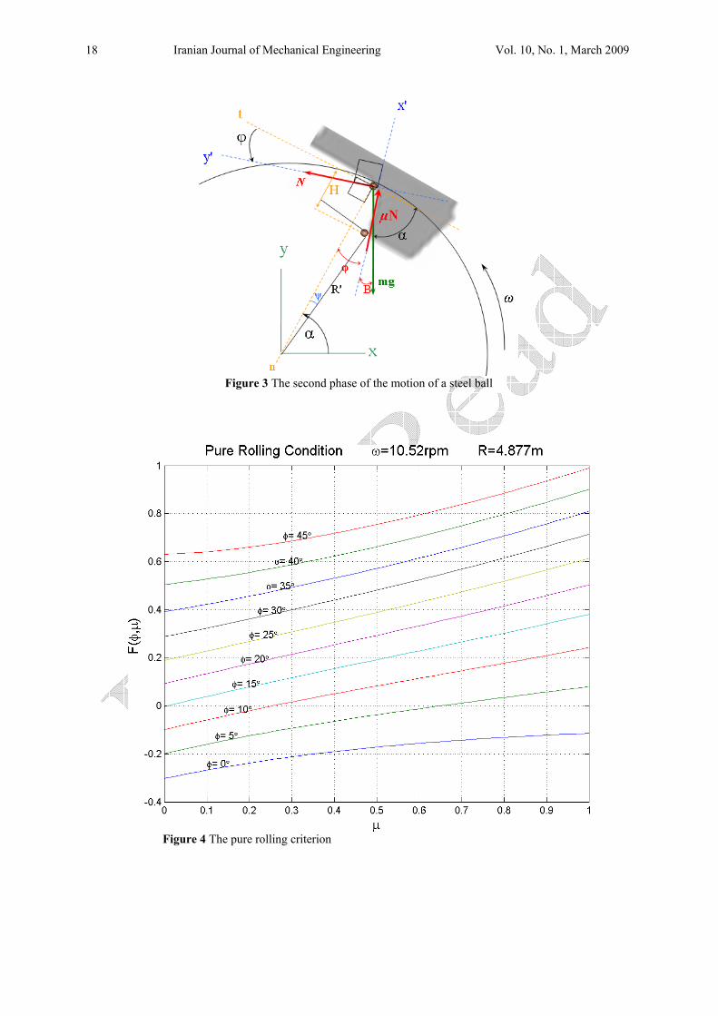
During the second phase the ball moves down on the liner face, the details of which are illustrated in Figure 3 along with the forces acting on the steel ball. Depending on the design of the mill (R, ω, φ) and the coefficient of friction between the lifter face and the steel ball (µ), the motion of the steel ball down the liner face can either be a pure rolling motion or a combined rolling and sliding motion, each having their own set of governing equations. The following paragraph explains the procedure for establishing a criterion for the pure rolling motion.
In a pure rolling motion down the inclined face of the liner, the angular accelerationαr of the ball and the linear acceleration for pure rolling motion are as follows, respectively:
25( ) 0.6 ( )3c c B B
B
gM I mgSin r mr Sinr
α α φ α α α φ⎛ ⎞= ⇒ + × = ⇒ = +⎜ ⎟⎝ ⎠
∑ r r r (5-a)
)(6.0 ϕαα +== gSinra Br
(5-b) The force-acceleration equations for ball’s motion in the t- and n- directions of Figure 3 in a pure rolling motion are:
)()(0)()(.
ϕααϕ
CosCosmgNCosmgCosNdirectiont =⇒=−⇒− (6-a)
)(6.0)()(. ϕααϕµ +==+−⇒− mgSinamSinmgCosFdirectionn (6-b) Simplifying Eq. (6-b) gives the friction force, which cannot exceed its maximum value:
NCos
SinSinmgF sµϕϕαα
µ ≤+−
=)(
)(6.0)( (7)
Finally, substituting the normal force N for pure rolling motion from Eq. (6-a) results in the criterion for pure rolling:
)(
)(6.0)(aCosSinSin
sϕααµ +−
≥ (8)
For a given mill with a fixed radius (R) and a constant angular velocity (ω), the pure rolling criterion can be restated by defining a function F(µ, φ) as follows:
( ) ( ) 0.6 ( ),( )s
Sin SinFCos
α α ϕµ ϕ µα
− += − (9)
Using the above notation, the pure rolling criterion can be stated as: ( ), 0F µ ϕ ≥ (10) A program has been written in MATLAB to compute the pure rolling criterion for any specific SAG mill using Eq. (10).
In order to obtain realistic numerical solutions, the dimensions and operating conditions of a full-scale 32×16 ft (9.75×4.88 m) industrial SAG mill have been used. The above-mentioned SAG mill, the dimensions and operating conditions of which have been summarized in Table 1 [6], operates in Sarcheshmeh Copper Mining Complex in Rafsanjan, Iran.
Figure 4 shows the pure rolling criterion for different lifter angles (φ) and coefficients of friction (µ), for the Sarcheshmeh SAG mill, in which positive values in the curves resemble pure rolling motion down the liner face and negative values resemble combined rolling and sliding motion.
The results indicate that for the mill being studied, for liner angles greater than 15° the motion down the liner face is pure rolling, regardless of the coefficient of friction. For smaller liner angles, however, in the case of small coefficients of friction the motion of the steel balls is of combined rolling and sliding and for larger coefficients of friction it is pure rolling. For
Iranian Journal of Mechanical Engineering Vol. 10, No. 1, March 2009 8
rectangular liner profiles (φ=0°), the motion is always combined rolling and sliding, regardless of the coefficient of friction.
If the ball moves down in a pure rolling motion, its angular velocity during the motion and linear velocity at the end of the path can be derived from the work and energy relation:
)(2.1)(35
21
222 ϕα
ϕωϕα
ϕω +⎥
⎦
⎤⎢⎣
⎡−=′⇒+⎟⎟
⎠
⎞⎜⎜⎝
⎛−=′⎟
⎠⎞
⎜⎝⎛ Sinr
CosH
rgSinr
CosHmgmr B
BBB (10)
1.2 ( )( )B B
HV r g r SinCos
ω α φφ
⎛ ⎞′= = − +⎜ ⎟⎝ ⎠
(12)
where H and rB are the lifter height and the ball radius, respectively, and ω′ is the angular velocity of the ball rolling down the liner face. Either the linear acceleration-displacement equation or the angular acceleration-velocity relation can be used to calculate the time it takes for the ball to roll down the liner face and reach the end of the path:
2 ( )1 .2 0.3 ( )
BH r
CosL at or t t
gSinφ
ω αα φ
⎡ ⎤−⎢ ⎥
⎣ ⎦′= = ⇒ =+
r (13)
In a combined rolling and sliding motion, the linear acceleration of the ball in the n-direction is obtained from the equation of motion in that direction:
)()()(
ϕαµα
CosCosggSinaamF knn −=⇒=∑ (14)
The angular acceleration of the ball αr
can also be calculated as:
)()(.5.1
32
)()( 2
ϕαµαα
ϕαµα
CosCos
rgmrr
CosCosmgIM
BkBBkGG =⇒=×⇒=∑ rrr (15)
The time it takes for the ball to reach the end of the path is:
)()()(
)(2
21
)(2
ϕα
µα
ϕϕ
CosCosggSin
rCos
H
ttarCos
HLk
B
B
−
⎥⎦
⎤⎢⎣
⎡−
=⇒=−= (16)
Finally, the ball’s velocity at the end of the path in a combined rolling and sliding motion is:
⎟⎟⎠
⎞⎜⎜⎝
⎛−×⎟⎟
⎠
⎞⎜⎜⎝
⎛−=⇒=
)()()(
)(2
ϕαµα
ϕ CosCosSinr
CosHgVtaV kB (17)
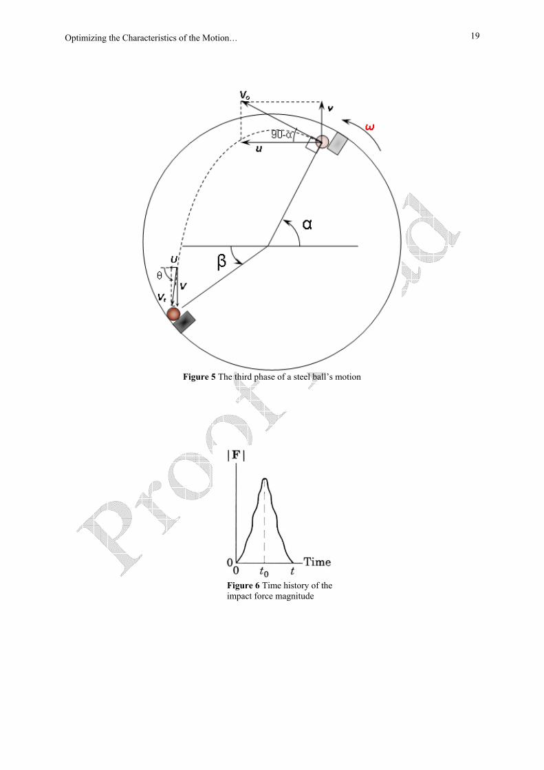
The third phase of the motion, as shown in Figure 5, is a projectile motion in which the steel ball leaves the tip of the lifter with an initial velocity Vo and collides with a liner on the opposite side with velocity Vt. For simplicity, the calculations of the third phase of the motion are performed in Cartesian coordinates (x- and y- coordinates of Figure 3). From the geometry, the components of the initial position vector are:
( ) ( )( )
Hx RCos CosCos
α α φφ
= − + (18-a)
( ) ( )( )
Hy RSin SinCos
α α φφ
= − + (18-b)
Based on geometrical calculations, the x- and y- components of the initial velocity vector due to the mill’s rotation (acting in the t-direction) are:
2
21 2 2 ( )
( )Hu R R H S in
Cosω α ψ
φ= − + − × − (19-a)
Optimizing the Characteristics of the Motion… 9
2
21 2 2 ( )
( )Hv R R H Cos
Cosω α ψ
φ= − + − × − (19-b)
in which the angle ψ, as shown in Figure 3, is determined as:
. tan( )tan HArcR H
ϕψ ⎡ ⎤= ⎢ ⎥−⎣ ⎦ (20)
There exists another velocity component for the ball, in the direction of the ball's motion down the face of the liner, denoted as the n ′− direction. This velocity vector depends on the nature of the motion, whether it is pure rolling or it's rolling with slippage. The x- and y- components of this velocity vector, for pure rolling, are:
2 1.2 ( ) ( )( ) B
Hu g r Sin CosCos
α φ α φφ
⎛ ⎞= − − + × +⎜ ⎟
⎝ ⎠ (21-a)
2 1.2 ( ) ( )( ) B
Hv g r Sin SinCos
α φ α φφ
⎛ ⎞= − − + × +⎜ ⎟
⎝ ⎠ (21-b)
For rolling with sliding, they are:
2( )2 ( ) ( )
( ) ( )B kH Cosu g r Sin Cos
Cos Cosαα µ α ϕ
ϕ ϕ⎛ ⎞ ⎛ ⎞
= − − × − × +⎜ ⎟ ⎜ ⎟⎝ ⎠ ⎝ ⎠
(22-a)
2( )2 ( ) ( )
( ) ( )B kH Cosv g r Sin Sin
Cos Cosαα µ α ϕ
ϕ ϕ⎛ ⎞ ⎛ ⎞
= − − × − × +⎜ ⎟ ⎜ ⎟⎝ ⎠ ⎝ ⎠
(22-b)
From the moment the ball leaves the lifter and during its projectile motion, the only force acting on it is its weight. The initial velocity of the ball at the start of its projectile motion is: 1 2(0)U u u= + (23) 1 2(0)V v v= + (24) Therefore, the components of the ball’s velocity and the position of the ball at an instant t after the start of the motion can easily be calculated: 1 2( ) .U t u u const= + = (25) 1 2( ) . ( )V t g t v v= − + + (26) The position of the ball at the instant t is: 1 2( ) ( )X t u u t x= + + (27)
21 2
1( ) ( )2
Y t gt v v t y= − + + + (28)
For the ball to hit the lifter Eqs. (27) and (28) should be combined such that: 2 2 2X Y R+ = (29) resulting in:
( ) ( )2
2 2 21 2 1 2
12
u u t x gt v v t y R⎡ ⎤+ + + − + + + =⎡ ⎤⎣ ⎦ ⎢ ⎥⎣ ⎦ (30)
Eq. (30) is then solved numerically for t, which in turn, can be used to give the angle β which dominates the position of the ball’s impact, as shown in Figure 5:
180arctan (deg)YX
βπ
⎛ ⎞= ×⎜ ⎟⎝ ⎠
(31)
The impact velocity Vt and the impact angle θ can also be determined as follows: 2 2
impactV U V= +r
(32)
Iranian Journal of Mechanical Engineering Vol. 10, No. 1, March 2009 10
( ) 180arctan (deg)( )
V tU t
θπ
⎛ ⎞= ×⎜ ⎟
⎝ ⎠ (33)
The effective impact angle, defined as the acute angle between the liner face surface and the velocity vector, can easily be figured out from the geometry of Figure 3 as: θ β θ′ = − (34) The normal or tangent components of the impact velocity vector can be easily calculated by multiplying impactV
rin Sinθ′or Cos θ′ , respectively.
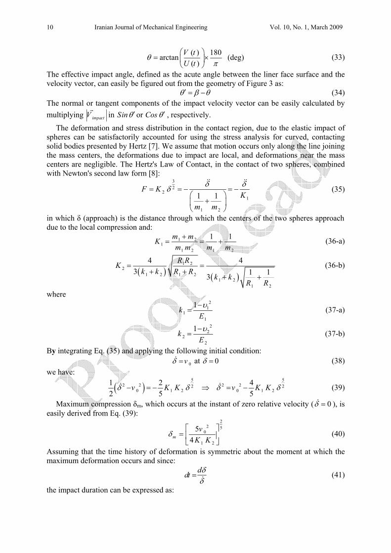
The deformation and stress distribution in the contact region, due to the elastic impact of spheres can be satisfactorily accounted for using the stress analysis for curved, contacting solid bodies presented by Hertz [7]. We assume that motion occurs only along the line joining the mass centers, the deformations due to impact are local, and deformations near the mass centers are negligible. The Hertz's Law of Contact, in the contact of two spheres, combined with Newton's second law form [8]:
32
21
1 2
1 1F K
Km m
δ δδ= = − = −⎛ ⎞
+⎜ ⎟⎝ ⎠
&& && (35)
in which δ (approach) is the distance through which the centers of the two spheres approach due to the local compression and:
1 21
1 2 1 2
1 1m mKm m m m+
= = + (36-a)
( ) ( )
1 22
1 2 1 21 2
1 2
4 43 1 13
R RKk k R R
k kR R
= =+ +
+ + (36-b)
where
2
11
1
1kEυ−
= (37-a)
2
22
2
1kEυ−
= (37-b)
By integrating Eq. (35) and applying the following initial condition: 0vδ =& at 0δ = (38) we have:
( )5 5
2 2 2 22 20 1 2 0 1 2
1 2 42 5 5
v K K v K Kδ δ δ δ− = − ⇒ = −& & (39)
Maximum compression δm, which occurs at the instant of zero relative velocity ( 0δ =& ), is easily derived from Eq. (39):
22 5
0
1 2
54m
vK K
δ⎡ ⎤
= ⎢ ⎥⎣ ⎦
(40)
Assuming that the time history of deformation is symmetric about the moment at which the maximum deformation occurs and since:
ddt δδ
= & (41)
the impact duration can be expressed as:
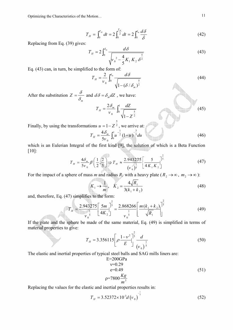
Optimizing the Characteristics of the Motion… 11
20 0 0
2 2H
H mTT
HdT dt dt
δ δδ
= = =∫ ∫ ∫ & (42)
Replacing from Eq. (39) gives:
50
2 20 1 2
245
m
HdT
v K K
δ δ
δ
=
−∫ (43)
Eq. (43) can, in turn, be simplified to the form of:
50
0 2
2
1 ( / )
m
H
m
dTv
δ δ
δ δ
=
−∫ (44)
After the substitution m
Z δδ
= and md dZδ δ= , we have:
1
500 2
2
1
mH
dZTv
Z
δ=
−∫ (45)
Finally, by using the transformations 521u Z= − , we arrive at:
31152
00
4 (1 )5
mHT u u du
vδ −−
= −∫ (46)
which is an Eulerian Integral of the first kind [9], the solution of which is a Beta Function [10]:
( )
25
10 1 25
0
4 1 2 2.943275 5,5 2 5 4
mH HT T
v K Kv
δ β⎡ ⎤⎛ ⎞= ⇒ ≈ ⎢ ⎥⎜ ⎟
⎝ ⎠ ⎣ ⎦ (47)
For the impact of a sphere of mass m and radius R1 with a heavy plate ( 2R →∞ , 2m →∞ ):
11Km
→ , 12
1 2
43( )
RK
k k=
+ (48)
and, therefore, Eq. (47) simplifies to the form:
2255
1 21 1
2 15 50 0
( )2.943275 5 2.8682664H
m k kmTK Rv v
⎡ ⎤⎡ ⎤ += = ⎢ ⎥⎢ ⎥
⎢ ⎥⎣ ⎦ ⎣ ⎦ (49)
If the plate and the sphere be made of the same material, Eq. (49) is simplified in terms of material properties to give:
( )
22 5
15
0
13.356115HdT
Ev
νρ⎡ ⎤−
= ⎢ ⎥⎣ ⎦
(50)
The elastic and inertial properties of typical steel balls and SAG mills liners are: E=200GPa ν=0.29 e=0.49 (51)
ρ=7800 3
Kgm
Replacing the values for the elastic and inertial properties results in:
( )15-3
03.52372 10HT d v−
= × (52)
Iranian Journal of Mechanical Engineering Vol. 10, No. 1, March 2009 12
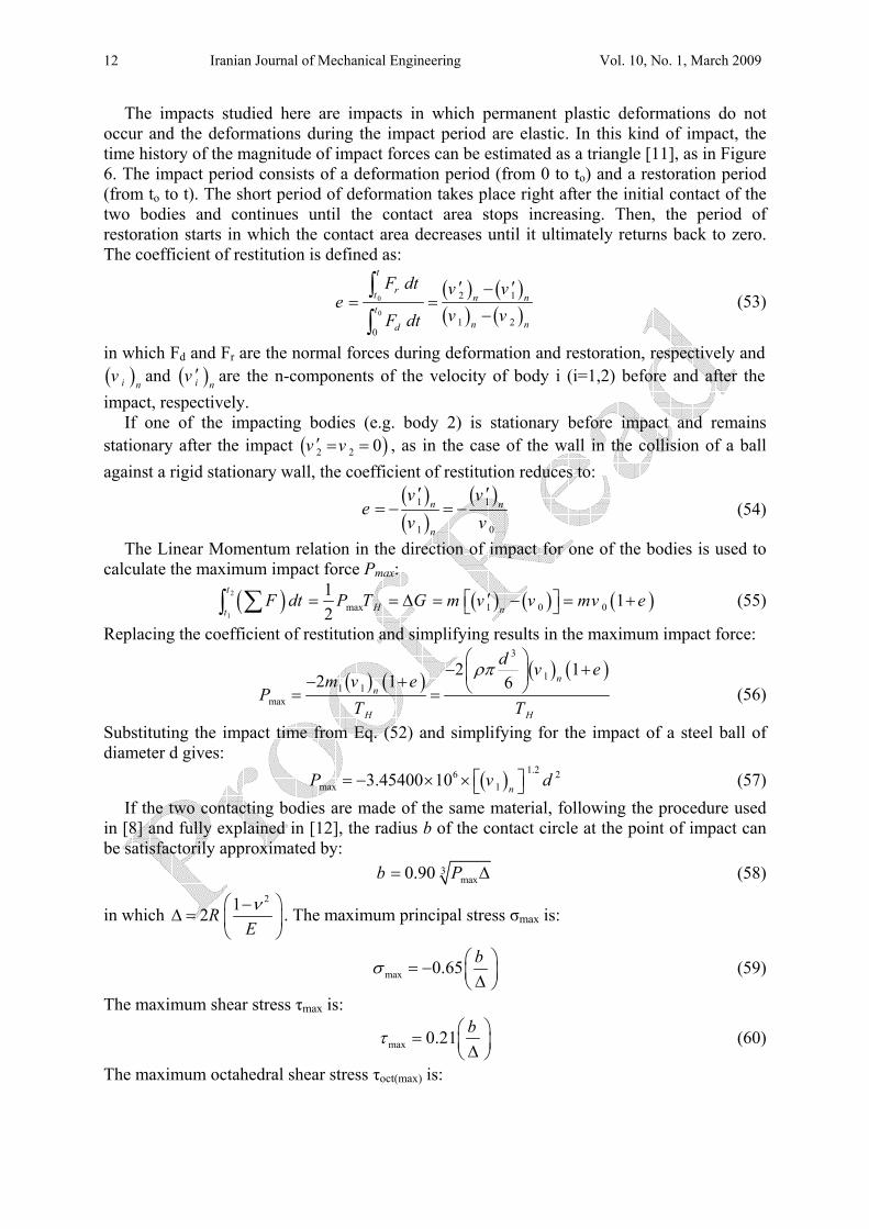
The impacts studied here are impacts in which permanent plastic deformations do not occur and the deformations during the impact period are elastic. In this kind of impact, the time history of the magnitude of impact forces can be estimated as a triangle [11], as in Figure 6. The impact period consists of a deformation period (from 0 to to) and a restoration period (from to to t). The short period of deformation takes place right after the initial contact of the two bodies and continues until the contact area stops increasing. Then, the period of restoration starts in which the contact area decreases until it ultimately returns back to zero. The coefficient of restitution is defined as:
( ) ( )( ) ( )
0
0
2 1
1 20
t
rt n nt
n nd
F dt v ve
v vF dt
′ ′−= =
−∫∫
(53)
in which Fd and Fr are the normal forces during deformation and restoration, respectively and ( )i nv and ( )i n
v ′ are the n-components of the velocity of body i (i=1,2) before and after the impact, respectively.
If one of the impacting bodies (e.g. body 2) is stationary before impact and remains stationary after the impact ( )2 2 0v v′ = = , as in the case of the wall in the collision of a ball against a rigid stationary wall, the coefficient of restitution reduces to:
( )( )
( )1 1
1 0
n n
n
v ve
v v′ ′
= − = − (54)
The Linear Momentum relation in the direction of impact for one of the bodies is used to calculate the maximum impact force Pmax:
( ) ( ) ( ) ( )2
1max 1 0 0
1 12
t
H ntF dt P T G m v v mv e′⎡ ⎤= = ∆ = − = +⎣ ⎦∑∫ (55)
Replacing the coefficient of restitution and simplifying results in the maximum impact force:
( ) ( ) ( ) ( )
3
11 1
max
2 12 1 6 n
n
H H
d v em v e
PT T
ρπ⎛ ⎞
− +⎜ ⎟− + ⎝ ⎠= = (56)
Substituting the impact time from Eq. (52) and simplifying for the impact of a steel ball of diameter d gives: ( ) 1.26 2
max 13.45400 10n
P v d⎡ ⎤= − × × ⎣ ⎦ (57) If the two contacting bodies are made of the same material, following the procedure used
in [8] and fully explained in [12], the radius b of the contact circle at the point of impact can be satisfactorily approximated by: 3
max0.90b P= ∆ (58)
in which 212R
Eν⎛ ⎞−
∆ = ⎜ ⎟⎝ ⎠
. The maximum principal stress σmax is:
max 0.65 bσ ⎛ ⎞= − ⎜ ⎟∆⎝ ⎠ (59)
The maximum shear stress τmax is:
max 0.21 bτ ⎛ ⎞= ⎜ ⎟∆⎝ ⎠ (60)
The maximum octahedral shear stress τoct(max) is:
Optimizing the Characteristics of the Motion… 13
(max) 0.196octbτ ⎛ ⎞= ⎜ ⎟∆⎝ ⎠
(61)
The maximum shear stresses τmax and τoct(max) occur at the depth zs from the free surface: 0.47sz b= (62) The maximum approach δm is:
max2.40mP
b Rδ
π⎛ ⎞∆
= ⎜ ⎟⎝ ⎠
(63)
3- Results and Discussion The most important step in optimization processes is to identify the main design variable. One of the main variables characterizing the motion of steel balls in a SAG mill is the separation angle α, shown schematically in Figure 2. As denoted by Eq. (4), the most important design variables and operating conditions affecting the separation angle in an industrial SAG mill are:
• Mill radius R; • Mill rotational velocityω ; • Liner inclination angleϕ ; • Liner surface coefficient of static friction µs.
The main characteristics dominating the impact of steel balls onto SAG mill shell liners are the impact position (X and Y or the angle β), impact velocity (Vimpact), impact angle (θ ′ ), and various impact stresses.As demonstrated by Eqs. (18)-(19), (21)-(22) and (25)-(28) the design variables and operating conditions of an industrial SAG mill affecting the impact position, the impact velocity, the impact angle and various impact stress values are:
• Mill radius R; • Mill rotational velocityω ; • Liner inclination angleϕ ; • Liner surface coefficient of static friction µs; • Lifter height H; • Steel ball size (radius) rB; • Liner surface coefficient of kinetic friction µk (in the case of combined rolling and sliding
motion down the liner face).
One approach to optimizing the motion of steel balls in a SAG mill is to separately measure the effect of each single one of the afore-mentioned design variables on the characteristics of the motion of steel balls and their impact onto SAG mill shell liners, while keeping all the other variables constant, in order to determine the net effect of each variable on the operating condition.
A second approach for determining the overall effect of these design variables on the operating condition is to measure the effect of a number of the design variables on the characteristics of steel ball motion and its impact onto SAG mill shell liners simultaneously, while keeping the rest of the design variables constant,.
As a demonstrative case study, the second approach has been followed in this paper and the effect of two variables, namely the lifter height (H) and the coefficient of friction (µ) on some of the main impact characteristics have been simultaneously investigated for the Sarcheshmeh SAG mill.
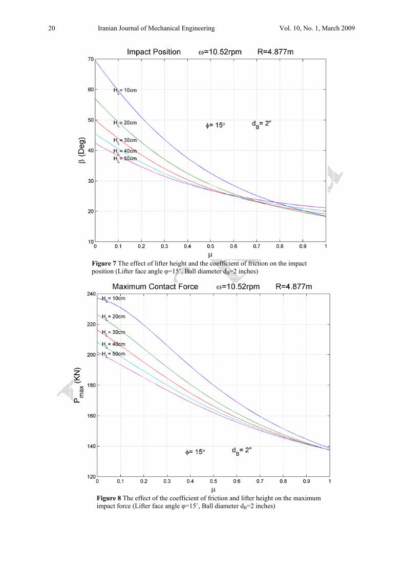
In order to determine the effect of the lifter height and the coefficient of friction on the impact position (β), the impact positions corresponding to various lifter heights were plotted
Iranian Journal of Mechanical Engineering Vol. 10, No. 1, March 2009 14
against the coefficient of friction (µ) for different combinations of lifter face angle (φ) and steel ball diameter (dB). Figure 7 illustrates the impact position for a lifter face inclination angle of 15˚ and a 2-inch diameter steel ball. Results indicate that the impact position tends to move upward (the angle β decreases) as the lifter height or the coefficient of friction increases. This is the direct result of the upward move of the separation point due to the increase in the time it take for the ball to roll or slide down the lifter face in higher lifters or for lifters which have a higher coefficient of friction.
To investigate the effect of the coefficient of friction and the lifter height on the maximum impact force (Pmax), the maximum impact forces corresponding to various lifter heights were plotted against the coefficient of friction (µ) for various steel ball diameters (dB) and lifter face angles (φ). Figure 8 illustrates the results for a lifter face inclination angle of 15˚ and a steel ball diameter of 2 inches. As shown in Figure 8, the maximum impact force decreases as the lifter height or the coefficient of friction increase.
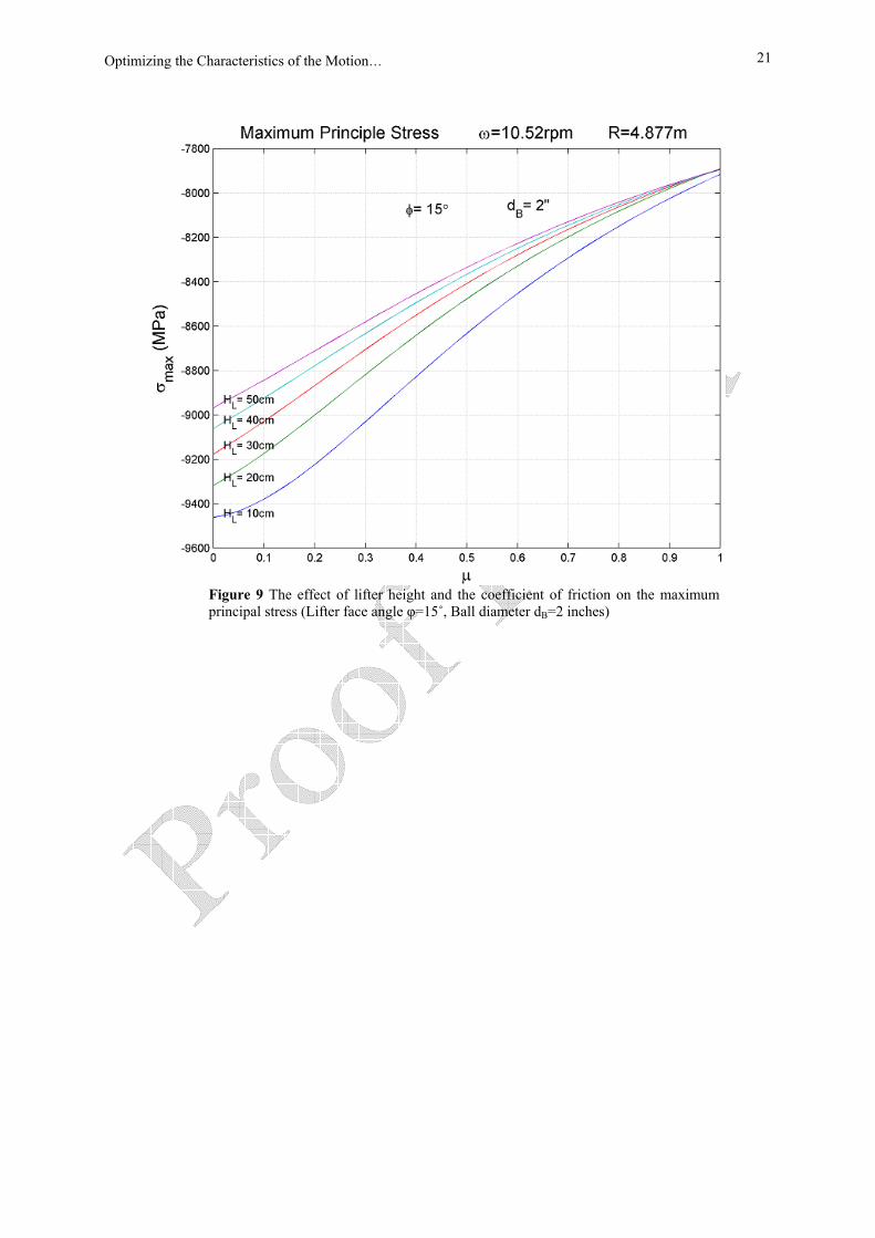
In order to demonstrate the effect of the coefficient of friction and the lifter height on the maximum principal stress (σmax), the curves corresponding to the maximum principal stresses due to different lifter heights were plotted against the coefficient of friction (µ) for various combinations of steel ball size (dB) and lifter face inclination angle (φ). Figure 9 shows the maximum principal stress for a lifter face angle of 15˚ and a 2-inch diameter steel ball. Results indicate that the absolute value of the maximum principal stress decreases as the lifter height or the coefficient of friction increase. 4- Conclusion In this research, the equations governing the motion of steel balls in an industrial SAG mill and their impact onto shell liners were derived in full details and were used in order to determine the effective parameters for optimizing the working conditions of the mill and to avoid severe impacts which lead to the breakage of SAG mill shell liners. Based on the afore-mentioned equations, the most important design variables governing the intensity of the impacts are lifter height H, the working coefficient of friction µ, lifter face inclination angle φ, steel ball size rB, mill rotational velocity ω, and mill size (radius) R. In order to optimize the operating conditions of a SAG mill and avoid severe impacts to its shell liners, which lead to the breakage of liners, the effect of these parameters need to be studied.
As a case study, the effect of the lifter height (H) and the coefficient of friction (µ) on some of the main impact characteristics were simultaneously investigated for an industrial SAG mill installed at Sarcheshmeh Copper Complex. It was shown that the lifter height (H) and the coefficient of friction (µ) have a significant effect on impact parameters and therefore on liner damage. Based on the results of the case study, as the lifter height or the coefficient of friction increases the impact position tends to move upward (the angle β decreases).
Moreover, considering the maximum impact force it was shown that the maximum impact force decreases as the lifter height or the coefficient of friction increase reducing the impact severity. Results indicated that the absolute value of the maximum principal stress decreases as the lifter height or the coefficient of friction increase.
Therefore, this study and its results emphasize the importance of determining the most important design variables and working conditions which influence the motion of steel balls in a SAG mill. The effect of these design variable can be determined in an optimization process and the results can be used in order to change the design of SAG mills or their working conditions to avoid damaging impacts onto the liners and hence liner breakage due to severe impacts.
Optimizing the Characteristics of the Motion… 15
References [1] Delboni, H. Jr., and Morrell, S., “A Load-interactive Model for Predicting the
Performance of Autogenous and Semi-Autogenous Mills”, KONA, Vol. 20, pp. 208-222, (2002).
[2] Grant, E., and Kalman, H., “Experimental Analysis of the Performance of an Impact Mill”, Advanced Powder Technology, Vol. 13, No. 3, pp. 233–247, (2002).
[3] Rajamani, R. K., Mishra, B. K., Latchireddi, S., Patra, T. N., and Prathy, S. K., On the Dynamics of Charge Motion in Grinding Mills, Proceedings of the Jan. D. Miller Symposium (SME Annual meeting), Salt Lake City, USA, Feb. (2005).
[4] Cleary, P. W., “Recent Advances in DEM Modeling of Tumbling Mills”, Minerals Engineering, Vol. 14, No. 10, pp. 1295-1319, (2001).
[5] Djordjevic, N., Shi, F. N., and Morrison, R., “Determination of Lifter Design, Speed and Filling Effects in AG Mills by 3D DEM” Minerals Engineering, Vol. 17, No. 11-12, pp. 1135-1142, (2004).
[6] Svedala Canada, “Data Sheets for 32×16 ft SAG Mill”, Sarcheshmeh Copper Mining Company, Rafsanjan, Iran, (2001).
[7] Carson, G., and Mulholland, A. J., “Particle Sizing using Hertz-zener Impact Theory and Acoustic Emission Spectra” Research Report No. 15, Department of Mathematics, University of Strathclyde, Glasgow, UK, Sept. (2005).
[8] Boresi, A. P., and Schmidt, R. J., “Advanced Mechanics of Materials”, 6th Edition, John Wiley and Sons, New Jersey, (2003).
[9] Whittaker, E. T., and Watson, G. N., “A Course in Modern Analysis”, 4th Edition, Cambridge University Press, Cambridge, (1990).
[10] Weisstein, E. W., “Beta Function”, MathWorld- A Wolfram Web Resource (2007). http://mathworld.wolfram.com/BetaFunction.html
[11] Meriam, J. L., and Kraige, L. G., “Engineering Mechanics: Dynamics”, 6th Edition, John Wiley and Sons, New Jersey, (2007).
[12] Ebrahimi-Nejad, Salman, “Analysis of the Dynamics of SAG Mill Contents and the Liner Behavior Due to Impact”, MSc Thesis, Mechanical Engineering Department, Shahid-Bahonar University, Kerman, (2007).
Iranian Journal of Mechanical Engineering Vol. 10, No. 1, March 2009 16
Nomenclature a : Linear acceleration of steel ball
Bd : Steel ball diameter e : Coefficient of restitution Fµ : Friction force
H : Lifter height m : Steel Ball mass N : Normal force acting on the ball from the lifter
wN : Normal force acting on the ball from the wall
maxP : Maximum impact force
R : Mill radius
Br : Steel ball radius
HT : Impact duration
sZ : Depth at which maximum shear stresses occur Greek symbols α : Separation angle αr
: Angular acceleration of steel ball β : Impact position with reference to the horizontal δ : Approach
mδ : Maximum approach ϕ : Lifter face angle
sµ : Static coefficient of friction
kµ : Kinetic coefficient of friction θ : Impact angle θ ′ : Effective impact angle σ : Principal stress τ : Shear stress
octτ : Octahedral shear stress ω : Angular velocity of the mill ω′ : Angular velocity of steel ball
Optimizing the Characteristics of the Motion… 17
Tables Table 1 Sarcheshmeh SAG mill Specifications Speed, rpm 10.52 rpmCritical Speed, rpm 13.66 rpmSpeed, % of critical speed 77% Vc Max Charge Filling, % of total mill volume 35% Ball Filling, % of total mill volume 15% Maximum Steel Ball Diameter 127 mm Nominal Mill Length 4.878 m Effective Grinding Length 4.420 m Inside Shell Diameter 9.754 m Aspect Ratio, diameter/length 2.2 Power Consumption 8.2 MW Number of Liners 2 × 60 Liner Thickness 78 mm Lifter Height (integral on the liner) 150 mm Lifter Inclination Angle 15°
Figures
Figure 1 Schematic Design of a typical SAG mill
Figure 2 The first phase of the motion of a steel ball
Iranian Journal of Mechanical Engineering Vol. 10, No. 1, March 2009 18
Figure 3 The second phase of the motion of a steel ball
Figure 4 The pure rolling criterion
Optimizing the Characteristics of the Motion… 19
Figure 5 The third phase of a steel ball’s motion
Figure 6 Time history of the impact force magnitude
Iranian Journal of Mechanical Engineering Vol. 10, No. 1, March 2009 20
Figure 7 The effect of lifter height and the coefficient of friction on the impact position (Lifter face angle φ=15˚, Ball diameter dB=2 inches)
Figure 8 The effect of the coefficient of friction and lifter height on the maximum impact force (Lifter face angle φ=15˚, Ball diameter dB=2 inches)
Optimizing the Characteristics of the Motion… 21
Figure 9 The effect of lifter height and the coefficient of friction on the maximum principal stress (Lifter face angle φ=15˚, Ball diameter dB=2 inches)
Iranian Journal of Mechanical Engineering Vol. 10, No. 1, March 2009 22
چكيدههای در آسياب (Shell Liners)جداره الينرهای های فوالدی و برخورد آنها به معادالت حاکم بر حرکت گلوله
متغيرهای ن يياستخراج و به منظور تعدر اين تحقيق ات کامل يبا جزئصنعتی (SAG Mill)خودشکن نيمهها به گلولهبرخوردهای شديد وقوع سازی شرايط کاری آسياب و به منظور اجتناب از بهينه درطراحی مؤثر
.اند شوند، به کار برده شده جداره آسياب میالينرهای که منجر به شکسته شدن الينرهای جداره آسياب فتر يلسطح ب يه شيزاو ،μ کاریب اصطکاک يضر، H (Lifter) فتريارتفاع ل: از درهای طراحی عبارتنين متغياφ ،اندازه گلوله فوالدی rB ،ابيآس یسرعت دوران ω، ابيو اندازه آس R. ط کاری و يسازی شرا نهيبه منظور به
. ردين پارامترها مورد مطالعه قرار گياهريک ازاثربايد ،نرهای جدارهيبه ال ها دگلولهياجتناب از برخوردهای شداصلی های بر برخی از شاخصه )μ(ب اصطکاک يو ضر (H)فتر ياثر ارتفاع لبه طورهمزمان ،قين تحقيدر ا
نشان داده بر اين اساس، . خودشکن مجتمع مس سرچشمه مورد مطالعه قرار گرفت مهياب نيبرخورد برای آسروی ياما حداکثر ن ؛شود به باال جابجا میرو ب اصطکاک، محل برخورد يا ضريفتر يش ارتفاع ليشدکه با افزا .است ابد که به معنی کاهش شدت برخوردي یم تنش اصلی کاهش ميمدر مطلق ماکزبرخورد و ق


![Thermomechanical Buckling of Simply Supported …jmee.isme.ir/article_20567_59428197b92e994c077f0008f1169483.pdfShahsiah and Eslami [3] analyzed the thermal buckling of FGM cylindrical](https://img.pdfslide.us/doc/110x75/5ab81ae47f8b9ad13d8c2d05/thermomechanical-buckling-of-simply-supported-jmeeismeirarticle2056759428197b92e.jpg)

![INDEX [australianmuseum.net.au] · INDEX Names of ... Ball's Pyramid, 230 Balolo worm, 220 · BanfielJ, E. J.; 301; Death of, 284 Banyans, 37 Barnacles. 109 ... Egypt, Toilet art,icles](https://img.pdfslide.us/doc/110x75/5baa383509d3f2b2778ba7bd/index-index-names-of-balls-pyramid-230-balolo-worm-220-banfielj.jpg)