Embed Size (px)
Citation preview
Keywords: Parallel robot, Spatial 3-RRS robot, Wheelchair stability control, Turn-over prevention 1 Introduction Various aspects of parallel robots have been taken into consideration in recent years. Researchers have recently concentrated on parallel platforms with less than 6 DoF (degrees of freedom) some of which are used in the structure design of robotic manipulators. Kinematic and dynamic analyses of low DOF parallel platforms are prerequisite for their perfect conceptual structural design. Little research has been done on the control of parallel robots in comparison with serial robots. Parallel robots or mechanisms have been more extensively used than serial robots due to their large ratio of payload to weight, high accuracy and speed in small work spaces [1-2]. Kinematics and dynamics of the platform of a 3-RPS parallel robot have been numerically analyzed [3-4].
* Corresponding Author, Associated Professor, Mechatronics Eng. Dept. , Islamic Azad University, South Tehran
Branch, Tehran, Iran [email protected] † Graduate Student, Mechatronics Eng. Dept., Islamic Azad University, South Tehran Branch, Tehran, Iran
[email protected] ‡ Graduate Student, Mechatronics Eng. Dept., Islamic Azad University, South Tehran Branch, Tehran, Iran
[email protected] § Assistant Professor, Mechatronics Eng. Dept., Islamic Azad University, South Tehran Branch, Tehran, Iran
M. Javadi*
Associated Professor
N. Afzalpour† Graduate Student
P. Jafari Taayemeh‡ Graduate Student
S. M. Khorsandijou§ Assistant Professor
Wheelchair Stabilization by the Control of a Spatial 3-RRS Mechanism A spatial parallel mechanism namely 3-RRS mechanism has been assigned to be attached to the seat of a standard electric wheelchair to prevent the turning over of the handicapped sitting on the wheelchair. The system of the wheelchair and the mechanism is a self-balancing robotic wheelchair and has coped with several road conditions. A stability control system calculates the proper moments on the basis of the height of the mass centre and the angle of the wheelchair. The control parameters have obtained and the revolute motors have been actuated by the control torques. Based on the simulation results of the system in MatLab, two types of stabilized wheelchairs, one of which has shown good results on several road conditions, have been built and tested.
Iranian Journal of Mechanical Engineering Vol. 17, No. 2, Sep. 2016
84
The speed and singularity of 4 and 5 DoF parallel platforms have been studied [5-6]. The characteristics of the motion of 3-RPS, 3-RRS and 3-UPU platforms have been found through the screw theory [7]. Direct and inverse kinematics of 3-RPS and 3-RSR parallel platforms have been analyzed [8-9]. Static balance of a 3-RRS parallel platform with the aid of sprung balance weights has been studied [10]. Robot control method might be designed on the basis of efficiency or on the basis of a model. The model based control methods require a dynamic model [11]. Six dependent coordinates is considered for the position and orientation of the moving platform of the spatial 3-RRS mechanism [12-13]. According to the Gruebler’s mobility criterion the 3-RRS mechanism, or in other words, the moving platform has three degrees of freedom with respect to the base platform of the spatial 3-RRS mechanism. The concept of control using the calculated torque has been proposed by Paul in (1972) [14]. It is a control method on the basis of the dynamic model of the robot. The model is required for the computation of the joint torques in the feedback loop. If the model is exact, the method will decouple the effect of the joints in the model [15]. The method of the calculated torque is a linear method for controlling a nonlinear system [16].
The model based torque control method presented by this article calculates the stabilizing control torques through a dynamic model. It belongs to the category of model based control methods. In the present article a 3-RRS spatial parallel mechanism forms a tripod being composed of a base plate and a movable plate with three similar extremities each of which has been made up of two links, one spherical and two revolute joints. The base platform is attached to a mobile wheelchair seat.
Singularity analysis and path planning with the working mode conversion have been studied for a 3-RRR planar parallel manipulator [18]. An improved wheelchair with obstacle and stair climbing ability has been presented [19]. Bioelectronics has been studied for a wireless human-wheelchair interface [20]. An electrically powered wheelchair has been adjusted to be monitored and controlled by mobile devices such as smart phones and tablets [21]. A robust intelligent controller has been applied to a class of nonholonomic electrically driven mobile robots [22]. A control system providing autonomy to all disabled people, has been achieved for designing an electric wheelchair moving in a three dimensional indoor environment [23]. Steering a motored wheelchair might be a hazardous task.
Experiments on robotic wheelchairs equipped by a monocular camera have proved the capability of the visual servoing approach to guide and assist a user navigating in a corridor [24]. A three dimensional vision-based system has been implemented to control an autonomous wheelchair mounted robotic manipulator with multiple-sensors [25]. Collaborative control of a robotic wheelchair has been proposed to support human-machine collaboration [26]. An aware wheelchair has been proposed with sensor networks [27]. It detects dangers within the distance of two meters, and suggests suitable actions [27]. A method has been proposed within which wheelchair robot imitates human like navigation by interacting with the surrounding environments [28]. It has been experimentally shown that the method is efficient for mobile robot navigations [28]. Design and development of a 4 wheel driven wheelchair has been proposed for indoor navigation with reduced wheel slippage and vibration [29]. Kinematics, actuator dynamics and wheels rolling resistance of a differential drive mobile robot has been studied [30]. An educational simulation tool has been proposed to analyze the kinematics and control of 2RPR-PR planar parallel robots [31]. 1.1 Model based computed torque control [14-16] Calculated torque denoted by is given by Eq. (1) using the torque found by robot inverse dynamic problem, i.e. , PD-controller gains, i.e. and , and closed loop dynamic error, i.e. defined by Eq. (2) within which is the desired joints’ angles.
Wheelchair Stabilization by the Control of a …
85
(1)
(2) According to the calculated torque method, the dynamic error i.e. e is assumed as the solution of a second order autonomous linear ordinary differential equation. Since the gains and are symmetric and positive definite, the dynamic error asymptotically approaches zero. Therefore the control of a sophisticated system such as a parallel robot can be simply solved. The gains and shown by Eqs. (3)-(4), are usually 3×3 diagonal matrices for a 3 DoF robot. They are found through controller design.
, , (3)
, , (4) Characteristic equation of a linearized model of a robot required in the calculated torque method might be assumed as Eq. (5) where is the damping ratio and is the natural frequency of the model.
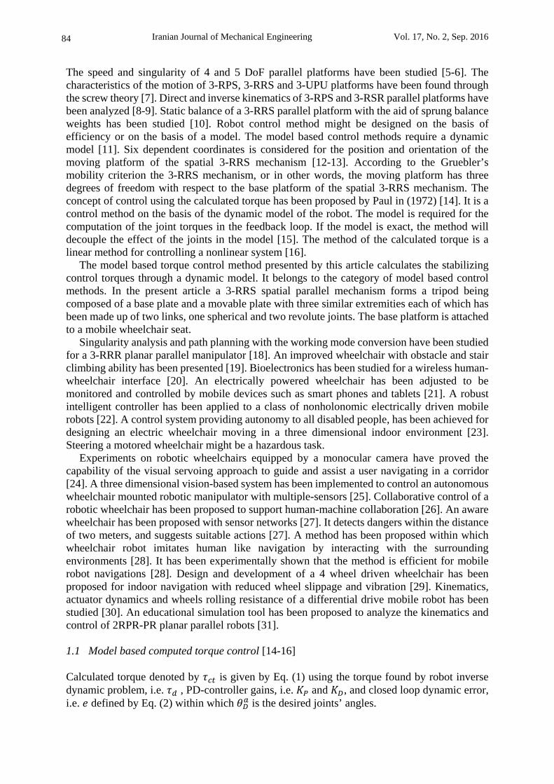
2 0 (5) Efficient performance is obtained by choosing the gains as and 2 . To avoid overshooting the damping ratio is chosen as 1. Therefore 2 and as a result the design problem reduces to a one-variable control design problem. Optimization techniques or trial and error methods might be used for finding the torques. 2 Kinematics The spatial 3-RRS mechanism of this article is illustrated by Figure (1). It consists of base and movable platforms with three supports being formed from two links, one spherical and two revolute joints. The axes of the two revolute joints of each support are parallel to each other and parallel to the base platform. The movable platform, namely the moving platform, has two angular and one vertically translational DoF with respect to the base platform. The base platform is also movable, since it is attached to the seat of a standard electric wheelchair. The coordinate reference frames O XYZ and P xyz in Figure (1) are respectively attached to the base and moving platforms being respectively perpendicular to Z and z axes. The geometric centers of the spherical and the two revolute joints are respectively depicted by A , B and C where i 1, 2 or 3. The triangles A A A and B B B are equilateral with R and r as their circumferential radii respectively.
Figure 1 Spatial 3-RRS mechanism
Iranian Journal of Mechanical Engineering Vol. 17, No. 2, Sep. 2016
86
3 Motion Equations Neglecting the friction of the spherical joints locating on the points A the spherical joint force action on the moving platform is denoted by Eq. (6).
. . . (6) Neglecting the friction of the second revolute joints locating on the points C , The moment equilibrium equation about the axis of the second revolute joint is given by Eq. (7) [17].
. . 0 (7)
Where is the inertia tensor of the second link of each support with respect to the frame OXYZ. 4 Torque Controller of 3-RRS robot In the present article, stability of the 3-RRS mechanism about roll and pitch and along Z axes has been controlled. The motion equations of the mechanism are needed for a PD-controller design. Considering the motion equations of the pervious section, the robot inverse dynamics can be solved to obtain the actuating torques required for a given motion of the mechanism. It should be noted that the forward dynamics is solved to obtain the motion caused by a given actuating torques.
The general form of the nonlinear motion equations are simply shown by Eq. (8) within which , τ and are respectively the inertia, applied forces or torques and the nonlinear part of the motion equations. In inverse dynamics the Eq. (8) are used to find the torque of actuator that is the controller input.
, (8) The system state vector and the time rate thereof are defined by Expressions (9).
, (9) The roll, pitch and height stability of a 3-RRS mechanism have been controlled by a PD- model based calculated torque controller. The closed loop linearized system is governed by Eqs. (10)-(12).
, (10)
(11)
(12) This system has been manufactured and has been empirically tested to set the controller design parameters, namely and . The proper values of them has been experimentally found as
45 and 11. It is a so-called trial and error algorithm for the design of the controller. The controller calculates the proper torques based on the wheelchair angles and height and stabilizes the wheelchair.

Wheelchair Stabilization by the Control of a …
87
5 Simulation Results Using Eqs. (10)-(12), the 3-RRS mechanism has been simulated by Simulink and SimMechanics toolboxes of MatLab. The magnitudes of the system parameters have been assumed as the Expressions (13). The preparation of the 3-RRS mechanism in Simulink and SimMechanics is shown by Figures (2-3). The dimensions, masses and inertia tensors are considered respectively in terms of , and . as follows:
0.10, 0.10, 0.12 10, 65
5 0 00 5 00 0 0.5
,25 0 00 33 00 0 17
(13)
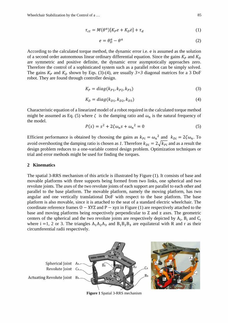
The angular velocity and acceleration and linear acceleration of the moving platform being represented by the linear acceleration of P have been shown by Figures (4-6) against time.
Figure 2 Computation of torque, angular velocity and acceleration of 3-RRS mechanism in Simulink
Figure3 Simulation of 3-RRS mechanism in SimMechanics
Iranian Journal of Mechanical Engineering Vol. 17, No. 2, Sep. 2016
88
Figure 4 Angular velocity of the moving platform versus time
Figure 5 Angular acceleration of the moving platform versus time
Figure 6 Moving platform acceleration versus time; Acceleration of P versus time
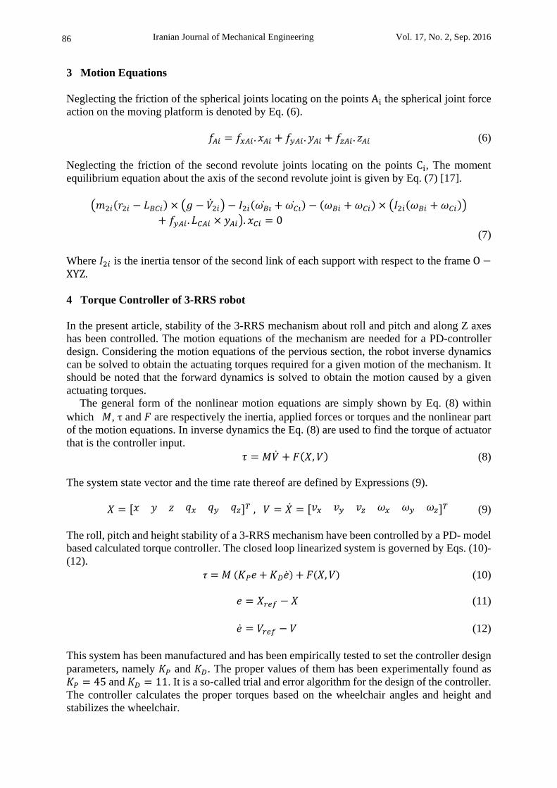
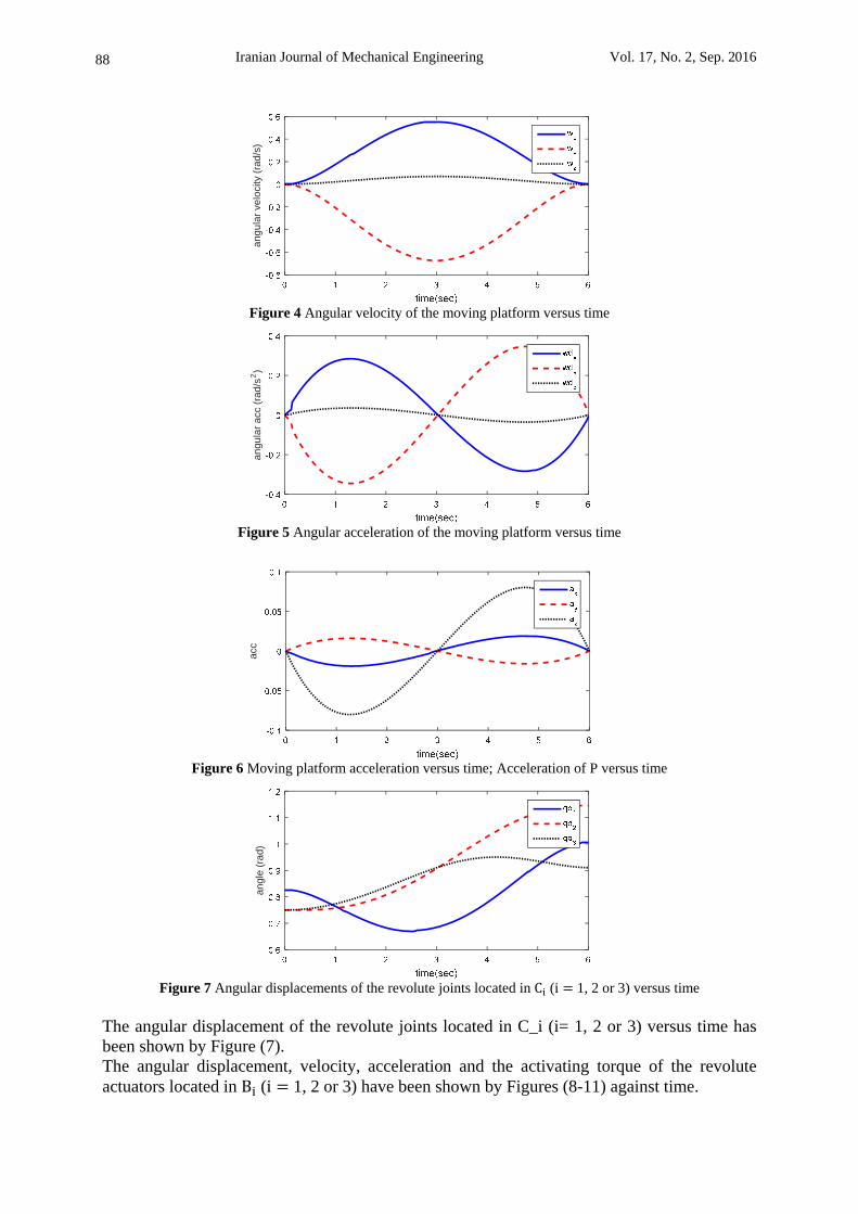
Figure 7 Angular displacements of the revolute joints located in C (i 1, 2 or 3) versus time
The angular displacement of the revolute joints located in C_i (i= 1, 2 or 3) versus time has been shown by Figure (7). The angular displacement, velocity, acceleration and the activating torque of the revolute actuators located in B (i 1, 2 or 3) have been shown by Figures (8-11) against time.
angu
lar
velo
city
(ra
d/s)
an
gu
lar
acc
(ra
d/s
2)
acc
an
gle
(ra
d)

Wheelchair Stabilization by the Control of a …
89
Figure 8 Angular displacements versus time for the revolute actuators located in B (i 1,2,3)
Figure 9 Angular velocity of the revolute actuators located in B (i 1, 2 or 3) versus time
Figure 10 Angular acceleration of the revolute actuators located in B (i 1, 2 or 3) versus time
Figure 11 Torque of the revolute actuators located in B (i 1, 2 or 3) versus time
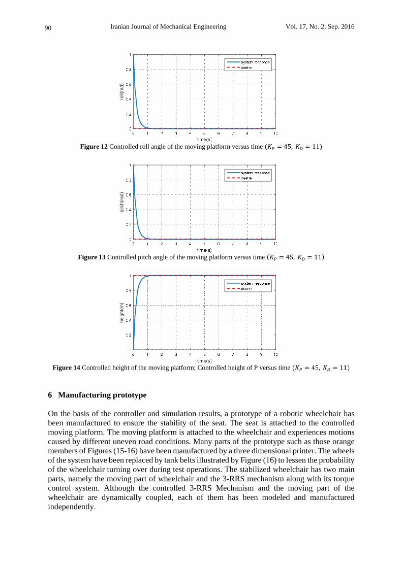
The controlled roll and pitch angles and the height of the moving platform represented by the height of P have been shown by Figures (12-14) against time. The controller design parameters have been set at 45 and 11.
an
gle
(ra
d)
angu
lar
velo
city
(ra
d/s)
an
gu
lar
acc
(ra
d/s
2)
driv
ing
mo
men
ts o
f leg
act
uato
rs(N
.m)
Iranian Journal of Mechanical Engineering Vol. 17, No. 2, Sep. 2016
90
Figure 12 Controlled roll angle of the moving platform versus time 45, 11
Figure 13 Controlled pitch angle of the moving platform versus time 45, 11
Figure 14 Controlled height of the moving platform; Controlled height of P versus time 45, 11
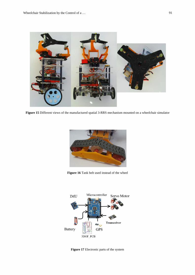
6 Manufacturing prototype On the basis of the controller and simulation results, a prototype of a robotic wheelchair has been manufactured to ensure the stability of the seat. The seat is attached to the controlled moving platform. The moving platform is attached to the wheelchair and experiences motions caused by different uneven road conditions. Many parts of the prototype such as those orange members of Figures (15-16) have been manufactured by a three dimensional printer. The wheels of the system have been replaced by tank belts illustrated by Figure (16) to lessen the probability of the wheelchair turning over during test operations. The stabilized wheelchair has two main parts, namely the moving part of wheelchair and the 3-RRS mechanism along with its torque control system. Although the controlled 3-RRS Mechanism and the moving part of the wheelchair are dynamically coupled, each of them has been modeled and manufactured independently.
roll(
rad
)pi
tch(
rad)
he
igh
t(m
)
Wheelchair Stabilization by the Control of a …
91
Figure 15 Different views of the manufactured spatial 3-RRS mechanism mounted on a wheelchair simulator
Figure 16 Tank belt used instead of the wheel
Figure 17 Electronic parts of the system
Iranian Journal of Mechanical Engineering Vol. 17, No. 2, Sep. 2016
92
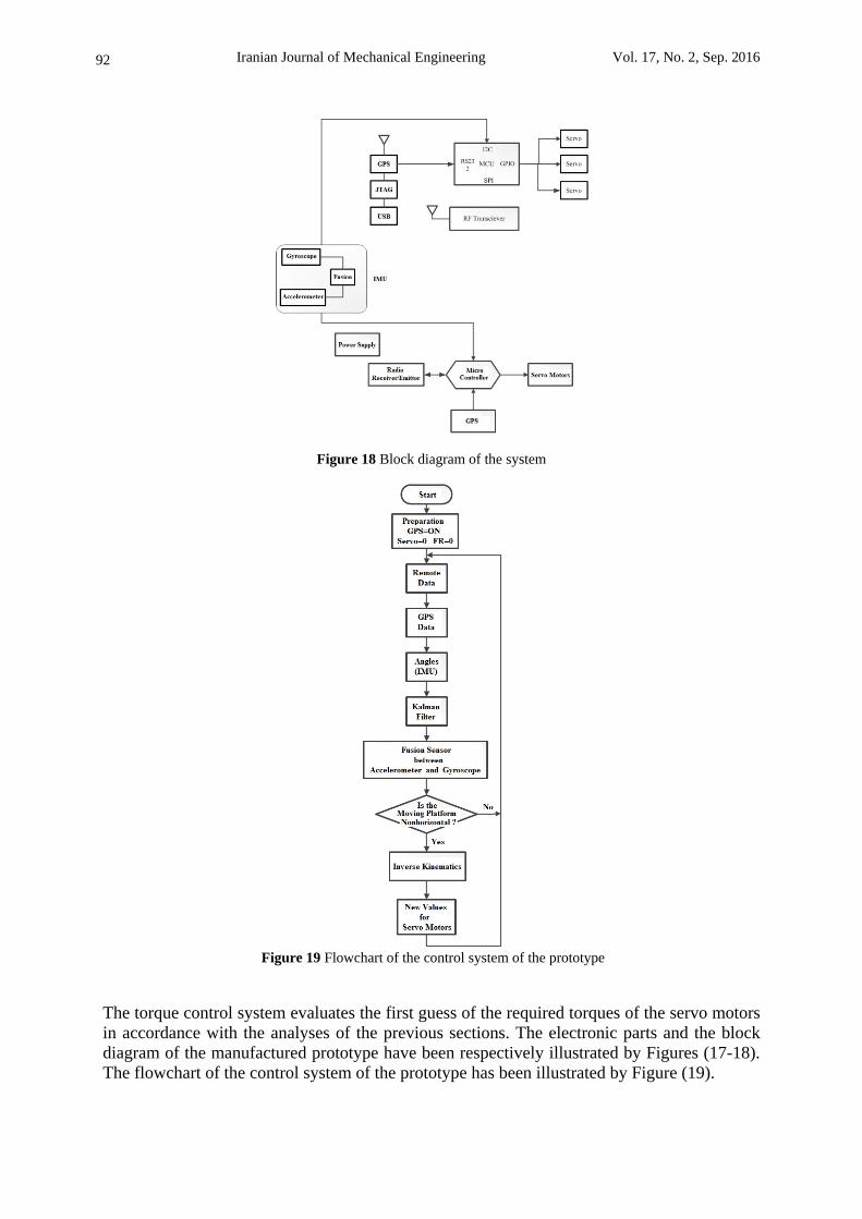
Figure 18 Block diagram of the system
Figure 19 Flowchart of the control system of the prototype
The torque control system evaluates the first guess of the required torques of the servo motors in accordance with the analyses of the previous sections. The electronic parts and the block diagram of the manufactured prototype have been respectively illustrated by Figures (17-18). The flowchart of the control system of the prototype has been illustrated by Figure (19).
Wheelchair Stabilization by the Control of a …
93
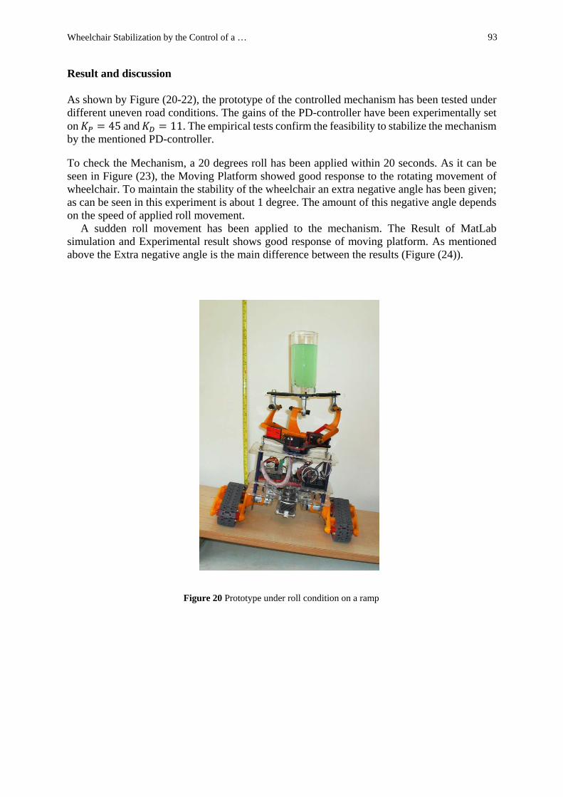
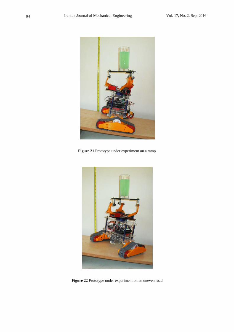
Result and discussion As shown by Figure (20-22), the prototype of the controlled mechanism has been tested under different uneven road conditions. The gains of the PD-controller have been experimentally set on 45 and 11. The empirical tests confirm the feasibility to stabilize the mechanism by the mentioned PD-controller.
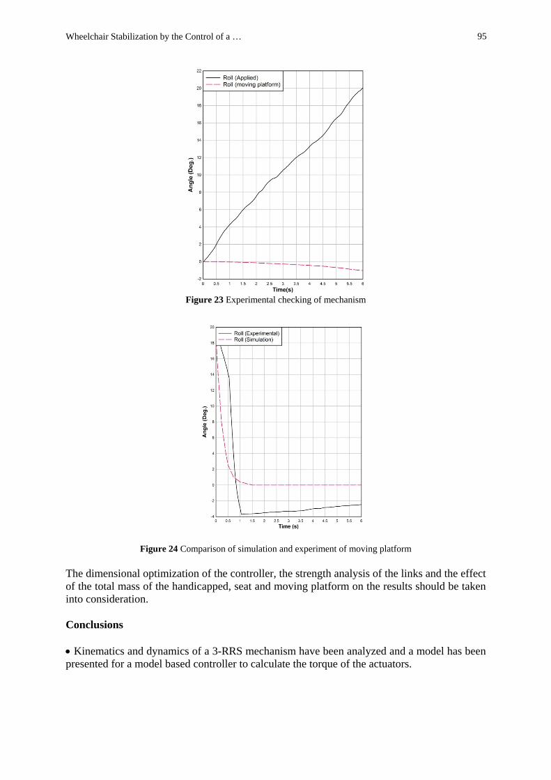
To check the Mechanism, a 20 degrees roll has been applied within 20 seconds. As it can be seen in Figure (23), the Moving Platform showed good response to the rotating movement of wheelchair. To maintain the stability of the wheelchair an extra negative angle has been given; as can be seen in this experiment is about 1 degree. The amount of this negative angle depends on the speed of applied roll movement.
A sudden roll movement has been applied to the mechanism. The Result of MatLab simulation and Experimental result shows good response of moving platform. As mentioned above the Extra negative angle is the main difference between the results (Figure (24)).
Figure 20 Prototype under roll condition on a ramp
Iranian Journal of Mechanical Engineering Vol. 17, No. 2, Sep. 2016
94
Figure 21 Prototype under experiment on a ramp
Figure 22 Prototype under experiment on an uneven road
Wheelchair Stabilization by the Control of a …
95
Figure 23 Experimental checking of mechanism
Figure 24 Comparison of simulation and experiment of moving platform
The dimensional optimization of the controller, the strength analysis of the links and the effect of the total mass of the handicapped, seat and moving platform on the results should be taken into consideration. Conclusions Kinematics and dynamics of a 3-RRS mechanism have been analyzed and a model has been presented for a model based controller to calculate the torque of the actuators.

Iranian Journal of Mechanical Engineering Vol. 17, No. 2, Sep. 2016
96
The mechanism has been manufactured and experimentally used to determine a proper value for the design parameters of the torque-model-based PD-controller. A trial and error algorithm has been used.
The obtained controller design parameters have been used for the simulation of the closed loop system in MatLab. The roll and pitch angles and the height of the moving platform have been to be controlled.
The system has been simulated only for one such controller set on 45 and 11. The simulation results and the experiments prove the capability of the controller to stabilize the mechanism.
Acknowledgement This project has been supported by Islamic Azad University – South Tehran Branch. References [1] Merlet, J.P., "Parallel Robots Solid Mechanics and Its Applications", Springer, Netherlands,
(2010). [2] Gosselin, C., "Kinematic Analysis Optimization and Programming of Parallel Robotic
Manipulators", Ph.D. Thesis, McGill University, Montreal, Canada, June 15, (1988). [3] Lee, K.M., and Shah, D.K., "Kinematic Analysis of a Three-degree-of-freedom In-parallel
Actuated Manipulator", IEEE J. of Robotics and Automation, Vo1. 4, Issue. 3, pp. 354-360, (1988).
[4] Lee, K.M., and Shah, D.K., "Dynamic Analysis of a Three-degrees-of-freedom In-parallel
Actuated Manipulator, IEEE Journal of Robotics and Automation, Vo1. 4, No. 3, pp. 361-367, (1988).
[5] Wang, J., and Gosselin, C.M., "Kinematic Analysis and Singularity Loci of Spatial Four-
degree-of-freedom Parallel Manipulators using a Vector Formulation", Transaction ASME, Journal of Mechanical Design, Vol. 120, pp. 555-558, (1998).
[6] Wang, J., and Gosselin, C.M., "Kinematic Analysis and Singularity Representation of
Spatial Five-degree-of-freedom Parallel Mechanisms", Int. J. of Robotic Systems, Vol. 14, pp. 851-869, (1997).
[7] Huang, Z., Tao, W.S., and Fang, Y.F., "Study on the Kinematic Characteristics of 3 DOF
In-parallel Actuated Platform Mechanisms", Mechanism and Machine Theory, Vol. 31, No. 8, pp. 999-1007, (1996)
[8] Buruncuk, K., and Tokad, Y., "On the Kinematics of a 3-DOF Stewart Platform",
International Journal of Robotic Systems, Vol. 16, No. 2, pp. 105-118, (1999). [9] Hertz, R.B., and Hughes, P.C., "Kinematic Analysis of a General Double-tripod Parallel
Manipulator", Mechanism and Machine Theory, Vol. 33, No. 6, pp. 683-696, (1998).
Wheelchair Stabilization by the Control of a …
97
[10] Wang, J., and Gosselin, C.M., "Static Balancing of Spherical Three-degree-of-freedom Parallel Mechanism", Mechanism and Machine Theory, Vol. 34, No. 3, pp. 437-452, (1999).
[11] Davliakos, I., and Papadopoulos, E., "Model-based Control of a 6-DOF Electrohydraulic
Stewart-gough Platform", Mechanism and Machine Theory, Vol. 43, pp. 1385-1400, (2008).
[12] Buruncuk, K., and Tokad, Y., "On the Kinematics of a 3-DOF Stewart Platform",
International Journal of Robotic System, Vol. 16, No. 2, pp. 105-118, (1999). [13] Li, J., Wang, J., and Liu, X., "An Efficient Method for Inverse Dynamics of Kinematically
Defective Parallel Platforms", Journal of Robotic Systems, Vol. 19, pp. 45-51, (2002). [14] Paul, R.P., “Modelling, Trajectory Calculation and Servoing of a Computer Controlled
Arm”, PhD Thesis in Comp. Sci., Stanford University, Stanford A. I. Memo AIM-177, Sept. (1972).
[15] John J. Craig, "Introduction to Robotics: Mechanics and Control", Addison-Wesley
Publishing Company, USA, (1989). [16] Husty, M.L., "An Algorithm for Solving the Direct Kinematics of General Stewart-Gough
Platforms", Mechanisms and Machine Theory, Vol. 31, No. 4, pp. 365-380, (1996). [17] Asada, H., "Robot Analysis and Control", John Wiley & Sons, Canada, (1986). [18] Liu, Sh., Qiu, Zh., and Zhang, X., "Singularity and Path-planning with the Working Mode
Conversion of a 3-DOF 3-RRR Planar Parallel Manipulator", Mechanism and Machine Theory, Vol. 107, pp. 166–182, (2017).
[19] Quaglia, G., and Nisi, M., "Design of a Self-leveling Cam Mechanism for a Stair Climbing
Wheelchair", Mechanism and Machine Theory, Vol. 112, pp. 84–104, (2017). [20] Mishra, S., Norton, J.J.S., Lee, Y., Lee, D.S., Agee, N., Chun, Y., Yeo, W.H., and Chen,
Y., "Soft, Conformal Bioelectronics for a Wireless Human-wheelchair Interface", Biosensors and Bioelectronics, Vol. 91, pp. 796–803, (2017).
[21] Valenzuela, V.L., Lucena, and V.F. Jr., "Remote Monitoring and Control of an Electric
Powered Wheelchair in an Assisted Living Environment", IFAC-papers Online, Vol. 49, No. 30, pp. 181–185, (2016).
[22] Boukens, M., Boukabou, A., and Chadli, M., "Robust Adaptive Neural Network-based
Trajectory Tracking Control Approach for Nonholonomic Electrically Driven Mobile Robots", Robotics and Autonomous Systems, Vol. 92, pp. 30–40, (2017).
[23] Baklouti, E., Amor, N.B., and Jallouli, M., "Reactive Control Architecture for Mobile
Robot Autonomous Navigation", Robotics and Autonomous Systems, Vol. 89, pp. 9–14, (2017).
Iranian Journal of Mechanical Engineering Vol. 17, No. 2, Sep. 2016
98
[24] Narayanan, V.K., Pasteau, F., Marchal, M., Krupa, A., and Babel, M., "Vision-based Adaptive Assistance and Haptic Guidance for Safe Wheelchair Corridor Following", Computer Vision and Image Understanding, Vol. 149, pp. 171–185, (2016).
[25] Jiang, H., Zhang, T., Wachs, J.P., and Duerstock, B.S., "Enhanced Control of a
Wheelchair-mounted Robotic Manipulator using 3-D Vision and Multimodal Interaction", Computer Vision and Image Understanding, Vol. 149, pp. 21–31, (2016).
[26] Saikia, A., ArifKhan, Md., Pusph, S., Tauhidi, S.I., Bhattacharyya, R., Hazarika, Sh.M.,
and Gan, J.Q., "CBDI-based Collaborative Control for a Robotic Wheelchair", Procedia Computer Science, Vol. 84, pp. 127-131, (2016).
[27] Miyachi, T., Buribayeva, G., Iga, S., and Furuhata, T., "A Study of aware Wheelchair with
Sensor Networks for Avoiding Two Meters Danger", Procedia Computer Science, Vol. 96, pp. 1004-1010, (2016).
[28] Hua, B., Hossain, D., Capi, G., Jindai, M., and Yoshida, I., "Human-like Artificial
Intelligent Wheelchair Robot Navigated by Multi-sensor Models in Indoor Environments and Error Analysis", Procedia Computer Science, Vol. 105, pp. 14-19, (2017).
[29] Kundu, A.S., Mazumder, O., Lenka, P.K., and Bhaumik, S., "Design and Performance
Evaluation of 4 Wheeled Omni Wheelchair with Reduced Slip and Vibration", Procedia Computer Science, Vol. 105, pp. 289-295, (2017).
[30] Leena, N., and Saju, K.K., "Modelling and Trajectory Tracking of Wheeled Mobile
Robots", Procedia Technology, Vol. 24, pp. 538-545, (2016). [31] Peidro, A., Reinoso, O., Gil, A., Marin, J.M., and Paya, L., "A Simulation Tool to Study
the Kinematics and Control of 2RPR-PR Parallel Robots", 11th IFAC Symposium on Advances in Control Education, Bratislava, Slovakia, pp. 268–273, (2016).
Nomenclature A, B, C Joints name
, PD-controller gains e Closed loop dynamic error
Desired joints’ angles. Damping ratio
Natural frequency of the model Spherical joint force action on the moving platform on the points A Inertia tensor of the second link of each support Inertia
τ Applied forces or torques Nonlinear part of the motion equations

Wheelchair Stabilization by the Control of a …
99
چكيده
عنوان يك الزام در زندگي امروزه ه استفاده از ويلچرهاي برقي براي افرادي كه داراي ناتواني جسمي هستند بحركتي، توانايي كنترل واژگوني ويلچر را نداشته و حفظ تعادل سخت علت مشكالت ه ديده ميشود. اين افراد ب
عنوان صندلي قرار داده شده تا در حفظ ه خواهد بود. در اين مقاله يك سيستم پايداركننده بر روي ويلچر بدر كليه شرايط جاده حالت افقي صندلي را حفظ نموده RRS-3تعادل استفاده كننده كمك نمايد. اين مكانيزم
با ايجاد زاويه مخالف در زمان مناسب مركز ثقل ويلچر را در محدوده بين چرخها حفظ ميكند. وصورت مدل عددي و تجربي مورد بررسي قرار گرفته و مقايسه نتايج عملكردي ه در اين مقاله اين مكانيزم ب
نشان داده شده است.