Embed Size (px)
Citation preview
General rights Copyright and moral rights for the publications made accessible in the public portal are retained by the authors and/or other copyright owners and it is a condition of accessing publications that users recognise and abide by the legal requirements associated with these rights.
• Users may download and print one copy of any publication from the public portal for the purpose of private study or research. • You may not further distribute the material or use it for any profit-making activity or commercial gain • You may freely distribute the URL identifying the publication in the public portal
If you believe that this document breaches copyright please contact us providing details, and we will remove access to the work immediately and investigate your claim.
Downloaded from orbit.dtu.dk on: Jun 26, 2018
Optimizations in Heterogeneous Mobile Networks
Popovska Avramova, Andrijana; Dittmann, Lars; Ruepp, Sarah Renée; Yan, Ying
Publication date:2016
Document VersionPublisher's PDF, also known as Version of record
Link back to DTU Orbit
Citation (APA):Popovska Avramova, A., Dittmann, L., Ruepp, S. R., & Yan, Y. (2016). Optimizations in Heterogeneous MobileNetworks. Technical University of Denmark (DTU).
DRAFT
Optimizations in Heterogeneous Mobile Networks
Andrijana Popovska Avramova
PhD Thesis
Technical University of DenmarkKgs. Lyngby, Denmark
February 2016
Technical University of DenmarkDepartment of Photonics EnginieeringNetworks Technologies and Service PlatformsØrsteds Plads 3432800 Kgs. LyngbyDENMARKTel: (+45) 4525 6352Fax: (+45) 4593 6581Web: www.fotonik.dtu.dkE-mail: [email protected]
Preface
This thesis presents a selection of the research work conducted during my Ph.D.study from August, 2010 until February, 2016. The project was mainly donein the Networks Technology and Service Platforms group at the Department ofPhotonics Engineering - Technical University of Denmark under supervision ofProfessor Lars Dittmann, Associate Professor Sarah Ruepp and Senior ResearcherYing Yan.
A six months research stay took place at Nokia Networks (Nokia - Bell Labs)in Aalborg, Denmark, under supervision of Professor Klaus I. Pedersen andAssociated Professor Hua Wang.
This Ph.D. study, the external research stay and participation in internationalconferences were financed by the Technical University of Denmark, The DanishAdvanced Technology Foundation through the project SAIRS - "Standard AgnosticIntelligent Radio Systems for the High Capacity Wireless Internet", as well as bytravel grants from Otto Mønsteds Fond and Oticon Fond.
iii

iv
Abstract
Heterogeneous Mobile Networks bring advantages over homogeneousdeployments in achieving the demand for mobile network capacity andcoverage not just outdoor rural and urban areas, but also to homes andenterprises where the large portion of the mobile traffic is generated.However, the heterogeneity in the mobile networks bring many challenges thatare discusses with this dissertation. More focus is placed on specific issues withindifferent areas of heterogeneity by proposing optimizations in order to overcomethe considered problems.
The heterogeneity of mobile networks, together with the densification of thebase stations, bring into a very complex network management and operationcontrol for the mobile operators. Furthermore, the need to provide always bestconnection and service with high quality demands for a joint overall networkresource management. This thesis addresses this challenge by proposing a universalhierarchical framework that enables flexible and effective management of diverseresources, namely spectral, optical and computational.
Dual Connectivity (DC) is an emerging architecture, which allows for simplifiedand flexible mobility management and enhanced load balancing among nodes.The independent control of the user’s transmit power at each node may causedegradation of the overall performance. In this line, a dedicated study of powerdistribution among the carriers is performed. An optimization of the powerallocation is proposed and evaluated. The results show significant performanceimprovement to the achieved user throughput in low as well as in high loads inthe cell. The flow control of the data between the nodes is another challenge foreffective aggregation of the resources in case of dual connectivity. As such, thisthesis discusses the challenges in providing efficient flow control, and investigatesan optimal traffic rate allocation method.
Cloud Radio Access Network (C-RAN) designates a leading technology for theRadio Access Network (RAN) architecture that is able to support dense deploy-ments, while ensuring network level energy and cost efficiency for the operator.This thesis thoroughly investigates the achievable multiplexing gains under C-RAN through a mathematical model based on the teletraffic theory. The work
v
vi Abstract
allows for evaluation of the key parameters and conditions for optimized celldeployment. The model can be applied to dynamically re-assign cells to a poolof baseband units. Furthermore, an evaluation of the various functional splitsin the baseband processing is introduced. The proposed mathematical modelquantifies the multiplexing gains and the trade-offs between centralization anddecentralization concerning the cost of the pool, fronthaul network capacity andresource utilization. Among the benefits that C-RAN brings is the possibility forsharing of the radio spectrum and the resources required for baseband processingamong operators. This thesis investigates strategies for active sharing of radioaccess among multiple operators and analyses the individual benefits dependingon the sharing degree.
Resumé(Summary in Danish)
Heterogene Mobilnet har væsentlige fordele i forhold til homogeneimplementeringer i at dække behovet til mobil netværkskapacitet ogdækning ikke bare udendørs i landdistrikter og byområder, men ogsåtil private hjem og virksomheder, hvor en stor del af den mobile trafikbliver genereret. Men den heterogenitet i de mobile netværk giver mangeudfordringer, der bliver diskuteret i denne afhandling. Afhandlingen har stor fokuspå specifikke problemstillinger inden for forskellige områder af heterogenitet vedat foreslå optimeringer for at overvinde de nævnte problemer.
Den heterogenitet af mobilnet sammen med tættere placering af basestationer,giver en meget kompleks netværks vedligeholdelse og drift kontrol for mobilop-eratørerne. Behovet for altid at give den bedste forbindelse og tjeneste med højkvalitet kræver en fælles, overordnet netværks ressource kontrol. Denne afhandlingomhandler denne udfordring ved at foreslå et universelt hierarkisk framework, dermuliggør fleksibel og effektiv styring af forskellige ressourcer, nemlig spektrale,optiske og processeringsmæssige.
Dual Connectivity (DC) er en ny arkitektur, som giver mulighed for forenklet ogfleksibel mobilitetsstyring og forbedret ressourcebalancering mellem knudepunkter.Den uafhængige kontrol af brugerens transmissionseffekt ved hvert knudepunktkan medføre forringelse af den samlede ydelse. Med hensyn til denne udfordring,er der inkluderet en dedikeret undersøgelse af effektfordeling mellem carriers. Enoptimering af effektallokering foreslås og evalueres. Resultaterne viser signifikantforbedring i den maksimale hastighed for lave samt høje belastninger i cellen.Kontrol af data flow mellem knuderne er endnu en udfordring for en effektivsammenlægning af ressourcerne i tilfælde af dual connectivity. Denne afhandlingdiskuterer udfordringerne i at udføre effektiv flow kontrol, og undersøger en optimaltrafik fordelingsmetode.
Cloud Radio Access Network (C-RAN) er betegnelsen for en førende teknologitil Radio Access Network (RAN) arkitektur, der er i stand til at understøttetætte udrulning og samtidig sikre netværks energi- og omkostningseffektivitet foroperatøren. Denne afhandling undersøger detaljeret de opnåelige multiplexing
vii
viii Resumé
gevinster ved CRAN gennem en matematisk model baseret på tele-trafik teori.Arbejdet giver mulighed for evaluering af de vigtigste parametre og betingelser foroptimeret celle design. Modellen kan anvendes til dynamisk at tildele celler til enpulje af baseband enheder. Endvidere bliver den givet evaluering af de forskelligefunktionelle splits i basebands processering. Den foreslåede matematiske modelkvantificerer de opnåelige multiplexing gevinster og kompromisser mellem centralis-ering og decentralisering vedrørende pool omkostninger, fronthaul netkapacitetog ressourceudnyttelse. Blandt de fordele, som C-RAN giver er muligheden forat dele radiofrekvenser og nødvendige ressourcer til baseband behandling mellemoperatørerne. Denne afhandling undersøger strategier for aktiv deling af radioadgang mellem flere operatører, og analyserer de individuelle fordele afhængigt afdelings grad.
Acknowledgements
I would not be able to complete the work that is presented in this thesis withouthelp of many people who were around me during my Ph.D. studies.
First and foremost, I would like to thank my supervisors: Professor LarsDittmann, Associate Professor Sarah Ruepp and Senior Researcher Ying Yan thathave steered me through the studies with their knowledge and encouragements. Iam grateful for the given opportunity and their trust in me.
I would like to thank all the members of Networks Technology & ServicePlatforms group that have created a pleasant working environment. I acknowledgemy colleagues Matteo Artuso and Aleksandra Checko who have been supportivein every way.
There are no words to express my gratitude to Dr. Villy Bæk Iversen forshowing me the world of teletraffic and teaching me the theory and differentanalytical models. He has been a great inspiration for many research directions inthis study.
I deeply admire Associate Professor Henrik L. Christiansen, who always hadtime for discussing various challenges in my study. His intriguing questions havebeen inspiring and have helped me to improve my work.
I am grateful to Klaus Pedersen and Dr. Hua Wang from Nokia Networks fortheir help and encouragements. Working as a visiting scholar in their researchgroup was a pleasant and rewarding experience.
Most importantly of all, I show extensive gratitude to my family that hasalways been there when I needed them most. I thank my mother who taughtme to be ambitious and never to give up. I thank my father who has been mytutor my whole life, showed me the love towards science and opened the doorsof the world of telecommunication. I would also like to thank my sister - herstrength and willingness have supported me and encouraged me ever since myfirst years at the university. I thank my husband whose optimisms have alwaysbrought brightness and confidence in my work. And last but not least, I thankmy daughters whose love, laugh and joy made this journey much more enjoyable.
ix

x
Ph.D Publications
Publications on the topic Optimizations in HeterogeneousMobile Networks
This dissertation only includes work for the topic on Optimizations in Heteroge-neous Mobile Networks. The PhD project resulted in 14 peer reviewed papers andthey are listed here in chronological order:
[1] A. Checko1st, A. Popovska Avramova1st, M. Berger, and H.L. Christiansen.“Evaluating C-RAN fronthaul functional splits in terms of network levelenergy and cost savings”. In: Journal of Communications and Networks,accepted for publication (2016)
[2] A. Popovska Avramova, H. Wang, L. Dittmann, and K. I. Pedersen. “Opti-mal Uplink Power Control for Dual Connected Users in LTE HeterogeneousNetworks”. In: IEEE 83rd Vehicular Technology Conference: VTC2016-Spring, accepted for publication, May 2016.
[3] A. Popovska Avramova, and V.B. Iversen. “Optimal Traffic Allocation forMulti-Stream Aggregation in Heterogeneous Networks”. In: IEEE 7th Int.Workshop on Heterogeneous and Small Cell Networks (HetSNets), IEEEGLOBECOM 2015, Dec. 2015.
[4] A. Popovska Avramova, H. L. Christiansen, and V.B. Iversen. “Cell De-ployment Optimization for Cloud Radio Access Networks using TeletrafficTheory”, In: The 11th Advanced International Conference on Telecommuni-cations, AICT 2015. July 2015.
[5] A. Popovska Avramova, and V.B. Iversen, “Radio Access Sharing Strategiesfor Multiple Operators in Cellular Networks”. In:The First IEEE Interna-tional Workshop on 5G & Beyond - Enabling Technologies and Application,IEEE ICC 2015, June 2015.
xi
xii Ph.D Publications
[6] A. Zakrzewska, A. Popovska Avramova, H. Christiansen, Y. Yan, A.Checko, A. Dogadaev, S. Ruepp, M.S. Berger, and L. Dittmann. “A Frame-work for Joint Optical-Wireless Resource Management in Multi-RAT, Het-erogeneous Mobile Networks”. In:Workshop on Optical-Wireless IntegratedTechnology for Systems and Networks (OWITSN) 2013, IEEE ICC 2013,June 2013, pp. 895–899.
[7] A. Zakrzewska, A. Popovska Avramova, S. Ruepp, M.S. Berger, and L.Dittmann. “CSMA-based SON Mechanism for Greening HeterogeneousNetworks”. In: INFOCOM Student Session, INFOCOM 2013, April 2013
[8] E. Kisielius, A. Zakrzewska, A. Popovska Avramova and S. Ruepp. “EnergyEfficiency in Self Organising Networks”. In: OPNETWORK 2013, Aug. 2013
[9] A. Popovska Avramova, Y. Ying, and L. Dittmann. “Evaluation of aCross Layer Scheduling Algorithm for LTE Downlink.” In: Telfor Journal5.1 (2013), pp. 26–31.
[10] A. Popovska Avramova, Y. Yan, S. Ruepp, and L. Dittmann. “ResourceAllocation: Current Issues and Future Directions”. In: 4th Nordic WorkshopOn System And Network Optimization For Wireless (SNOW 2013). Apr.2013.
[11] A. Dogadaev, A. Checko, A. Popovska Avramova, A. Zakrzewska, Y. Yan,S. Ruepp, M.S. Berger, L. Dittmann, and H. Christiansen, H. “Trafic SteeringFramework for Mobile-Assisted Resource Management in HeterogeneousNetworks”. In: Ninth International Conference on Wireless and MobileCommunications, ICWMC. July 2013.
[12] A. Popovska Avramova, Y. Yan, and L. Dittmann. “Cross layer schedul-ing algorithm for LTE downlink”. In: 20th Telecommunications Forum(TELFOR), Nov. 2012, pp. 307–310.
[13] A. Popovska Avramova, Y. Yan, and L. Dittmann. “Modeling and Sim-ulation of Downlink Subcarrier Allocation Schemes in LTE”. In: OPNET-WORK, Aug. 2012.
[14] A. Popovska Avramova, Y. Yan, and L. Dittmann. “Modeling of Band-width Aggregation over Heterogeneous Wireless Access Networks”. In: OP-NETWORK, Aug. 2012

xiii
Publications on the topic Wireless Sensor Networks
[15] B. Stojkoska and A. Popovska Avramova. “Wireless Sensor NetworksFramework for Indoor Temperature Regulation”. In: 8th Annual South-EastEuropean Doctoral Student Conference. Sept. 2013, pp. 354–364.
[16] B. Stojkoska, A. Popovska Avramova, and P. Chatzimisios. “Applica-tion of Wireless Sensor Networks for Indoor Temperature Regulation”. In:International Journal of Distributed Sensor Networks (2014). Article ID502419.
Publications on the topic Critical Communications andPublic Safety Networks
[17] S. Michail, A. Popovska Avramova, and L. Dittmann. “MIH BasedMobility for TETRA-LTE Network”. In: ICT Innovations 2013. Sept. 2013.
[18] A. Popovska Avramova, S. Ruepp, and L. Dittmann. “Towards FutureBroadband Public Safety Systems: Current Issues and Future Directions”.In: International Conference on Information and Communication TechnologyConvergence (ICTC). Oct. 2015, pp. 74–79.
Contents
Preface iii
Abstract v
Resumé vii
Acknowledgements ix
Ph.D Publications xi
List of Figures xv
List of Tables xvii
Acronyms xix
1 Introduction 11.1 Background on Heterogeneous Mobile Networks . . . . . . . . . . . 11.2 Thesis Structure . . . . . . . . . . . . . . . . . . . . . . . . . . . 13
2 Network Resource Management 172.1 Introduction . . . . . . . . . . . . . . . . . . . . . . . . . . . . . . 172.2 Related Work . . . . . . . . . . . . . . . . . . . . . . . . . . . . 182.3 Network Management Framework . . . . . . . . . . . . . . . . . . 192.4 SON and congnitive aspects . . . . . . . . . . . . . . . . . . . . 262.5 Internal architecture and communication of modules . . . . . . . . 282.6 Control Mechanism . . . . . . . . . . . . . . . . . . . . . . . . . 292.7 Summary . . . . . . . . . . . . . . . . . . . . . . . . . . . . . . . . 31
3 Uplink Power Control for Dual Connected Users 333.1 Introduction . . . . . . . . . . . . . . . . . . . . . . . . . . . . . . 343.2 Dual Connectivity . . . . . . . . . . . . . . . . . . . . . . . . . . 35
xiv
Contents xv
3.3 Uplink Power Control . . . . . . . . . . . . . . . . . . . . . . . . 423.4 Enhanced Uplink Power Control . . . . . . . . . . . . . . . . . . . 443.5 Performance Analysis . . . . . . . . . . . . . . . . . . . . . . . . 493.6 Conclusion . . . . . . . . . . . . . . . . . . . . . . . . . . . . . . . 54
4 Optimal Traffic Allocation for Multi-Stream Aggregation 574.1 Introduction . . . . . . . . . . . . . . . . . . . . . . . . . . . . . 584.2 Related work . . . . . . . . . . . . . . . . . . . . . . . . . . . . . 584.3 System Model . . . . . . . . . . . . . . . . . . . . . . . . . . . . 604.4 Optimal Traffic Rate Allocation . . . . . . . . . . . . . . . . . . . 634.5 Tractable Problem Formulation . . . . . . . . . . . . . . . . . . . 654.6 Numerical Analysis and Performance Evaluation . . . . . . . . . . 664.7 Conclusion . . . . . . . . . . . . . . . . . . . . . . . . . . . . . . . 71
5 Cloud Radio Access Network 735.1 Introduction . . . . . . . . . . . . . . . . . . . . . . . . . . . . . . 745.2 Related Work . . . . . . . . . . . . . . . . . . . . . . . . . . . . 755.3 Direct Routing Network Model . . . . . . . . . . . . . . . . . . . 765.4 Discussion on multiplexing gain and BBU pool dimensioning . . . 805.5 Multiplexing Gains for Centralized Baseband Processing . . . . . . 835.6 Evaluation of Split Base Station Processing . . . . . . . . . . . . 895.7 Conclusion . . . . . . . . . . . . . . . . . . . . . . . . . . . . . . . 97
6 Resource Sharing Strategies for Mobile Operators 1016.1 Introduction . . . . . . . . . . . . . . . . . . . . . . . . . . . . . 1026.2 Related Work . . . . . . . . . . . . . . . . . . . . . . . . . . . . 1086.3 Resource sharing at a single cell . . . . . . . . . . . . . . . . . . 1096.4 Resource sharing at a network level . . . . . . . . . . . . . . . . . 1136.5 Conclusion . . . . . . . . . . . . . . . . . . . . . . . . . . . . . . . 117
7 Thesis summary 1197.1 Future Research Directions . . . . . . . . . . . . . . . . . . . . . . 121
Bibliography 123

xvi
List of Figures
1.1 Multi-RAT heterogeneous network. . . . . . . . . . . . . . . . . . . . 21.2 An example of heterogeneous network: mixture of high and low power
nodes. . . . . . . . . . . . . . . . . . . . . . . . . . . . . . . . . . . . 71.3 Examples on Carrier Aggregation in heterogeneous network. . . . . . 81.4 Base Station Evolution. . . . . . . . . . . . . . . . . . . . . . . . . . 101.5 C-RAN Architectures. . . . . . . . . . . . . . . . . . . . . . . . . . . 121.6 Thesis structure. . . . . . . . . . . . . . . . . . . . . . . . . . . . . . . 14
2.1 Scope of RAN resource management. . . . . . . . . . . . . . . . . . 202.2 Time scale of management functionalities. . . . . . . . . . . . . . . . . 212.3 Hierarchical Network Management framework. . . . . . . . . . . . . . 232.4 Inter-RAT management cooperation. . . . . . . . . . . . . . . . . . . 252.5 The cognitive loop based on [85] . . . . . . . . . . . . . . . . . . . . . 272.6 Inner architecture for ultra-fast module . . . . . . . . . . . . . . . . . 282.7 Example of module communication between different levels . . . . . . 302.8 Example of module communication among modules in one level . . . 302.9 Communication time frame . . . . . . . . . . . . . . . . . . . . . . . . 31
3.1 Deployment scenario for Dual Connectivity . . . . . . . . . . . . . . . 363.2 Control Plane Architecture for Dual Connectivity and SeNB management 373.3 User Plane Architecture for Dual Connectivity . . . . . . . . . . . . . . 373.4 Distribution of UE maximum power . . . . . . . . . . . . . . . . . . 403.5 Cases for uplink transmissions in Dual Connectivity . . . . . . . . . . . 443.6 Ilustration of the proposed power control for Dual Connectivity . . . . . 473.7 Average UE transmission power for different traffic loads . . . . . . . 523.8 Interference over thermal noise for different traffic loads . . . . . . . . 533.9 50%-ile user throughput for different traffic loads . . . . . . . . . . . . 543.10 5%-ile user throughput for different traffic loads . . . . . . . . . . . . . 54
4.1 System for multi-stream aggregation over heterogeneous networks . . . 614.2 Data rate performance under increased demand for GBR traffic . . . . . 67
xvii
xviii List of Figures
4.3 Transmission delay variation under increased demand for GBR traffic . 684.4 Buffering time variation under increased demand for GBR traffic . . . 684.5 Data rate performance under increased demand for nonGBR traffic . . 694.6 Transmission delay variation under increased demand for nonGBR traffic 704.7 Buffering time variation under increased demand for nonGBR traffic . 70
5.1 Multiplexing in single link . . . . . . . . . . . . . . . . . . . . . . . . . 775.2 Analysis of multiplexing gain with aggregation. . . . . . . . . . . . . 805.3 Blocking probability dependency on group dimensioning. . . . . . . . 825.4 Dynamic base station load within daytime [135]. . . . . . . . . . . . . . 845.5 Optimal dimensioning of BBU pool. . . . . . . . . . . . . . . . . . . 865.6 Multiplexing Gains in BBU pool. . . . . . . . . . . . . . . . . . . . . . 875.7 Dynamic allocation of RRHs to a BBU pool. The assignment is defined
by different colors. . . . . . . . . . . . . . . . . . . . . . . . . . . . . 885.8 Optimal deployment for variable load. . . . . . . . . . . . . . . . . . 895.9 RAN Architecture for different functional splits. . . . . . . . . . . . . . 915.10 Model of C-RAN with N cells, resource definition and offered traffic as
PDCP-RLC and UE-Cell split. . . . . . . . . . . . . . . . . . . . . . 935.11 Multiplexing gain in BBU pool: PDCP-RLC versus BB-RF split. . . . 965.12 Fronthaul network dimensioning. . . . . . . . . . . . . . . . . . . . . . 975.13 PRB Utilization. . . . . . . . . . . . . . . . . . . . . . . . . . . . . . . 975.14 Weighted cost evaluation based on gains . . . . . . . . . . . . . . . 98
6.1 Example of resource sharing opportunities. . . . . . . . . . . . . . . . 1026.2 Radio resource sharing based on virtualization. . . . . . . . . . . . . . . 1046.3 Network sharing based on SDN and C-RAN. . . . . . . . . . . . . . . 1056.4 Mobile operator architecture by virtualization . . . . . . . . . . . . . . 1076.5 State transition diagram for sharing radio resources at single BS between
two operators . . . . . . . . . . . . . . . . . . . . . . . . . . . . . . 1106.6 Impact on blocking probability due to 10 % increase in offered traffic for
Operator A. . . . . . . . . . . . . . . . . . . . . . . . . . . . . . . . 1126.7 Impact on blocking probability due to 10 % increase in offered traffic for
Operator B. . . . . . . . . . . . . . . . . . . . . . . . . . . . . . . . 1126.8 Sharing strategies for Operator A under traffic variations of Operator B. 1136.9 Sharing strategies for Operator B under traffic variations of Operator B. 1136.10 Blocking probabilities in Small Cell 1. . . . . . . . . . . . . . . . . . 1156.11 Blocking probabilities in Small Cell 2. . . . . . . . . . . . . . . . . . 1166.12 Blocking probabilities in Small Cell 3. . . . . . . . . . . . . . . . . . 1166.13 Comparison of carried traffic . . . . . . . . . . . . . . . . . . . . . . . 117
List of Tables
3.1 Notation . . . . . . . . . . . . . . . . . . . . . . . . . . . . . . . . . 463.2 Simulation Parameters . . . . . . . . . . . . . . . . . . . . . . . . . 50
4.1 Notation of parameters used . . . . . . . . . . . . . . . . . . . . . . 62
5.1 Direct Routing Network Representation . . . . . . . . . . . . . . . . 795.2 Direct routing equivalent to C-RAN that covers a mixture of office and
home cells . . . . . . . . . . . . . . . . . . . . . . . . . . . . . . . . 855.3 Network related parameters . . . . . . . . . . . . . . . . . . . . . . . 865.4 Direct routing equivalent to a functional split in C-RAN . . . . . . . . 93
xix

xx List of Tables
Acronyms
3GPP Third Generation Partnership Project
AI Artificial Intelligence
BBU Baseband Unit
BS Base Station
C-RAN Cloud Radio Access Network
CA Carrier Aggregation
CAPEX CAPital EXpenditure
CC Component Carrier
CCO Coverage and Capacity Optimization
CN Core Network
CoMP Coordinated Multi-Point
CPRI Common Public Radio Interface
CQRs Channel Quality Reports
CRE Cell Range Expansion
CRRM Common Radio Resource Management
CSMA Carrier Sense Multiple Access
DC Dual Connectivity
DL downlink
xxi
xxii Acronyms
eGAN enhanced Generic Access Network
eICIC enhanced Inter-cell Interference Coordination
EPC Evolved Packet Core
ePDG Evolved Packet Data Gateway
HetNets Heterogeneous Networks
I-WLAN Interworking WLAN
IEEE Institute of Electrical and Electronics Engineers
IETF Internet Engineering Task Force
IMS IP Multimedia Subsystem
IQ In-phase/Quadrature
JRRM Joint Radio Resource Management
KPI Key Performance Indicators
LAA License Assisted Access
LPN Low Power Node
LPNs Low Power Nodes
MAC Media Access Control
MIH Media Independent Handover
MIMO Multiple Input Multiple Output
MLB Mobility Load Balancing
mmWave milimeter-wave
MRO Mobility Robusteness Optimization
MRRM Multi-access Radio Resource Management
OBSAI Open Base Station Architecture Initiative
OPEX OPerating EXpenditure
Acronyms xxiii
ORI Open Radio equipment Interface
P-GW Packet Data Network Gateway
PDCP Packet Data Convergence Protocol
PHY Physical
QoS Quality of Service
RAN Radio Access Network
RATs Radio Access Technologies
RIWCoS Reconfigurable Interoperability of Wireless Communications System
RRH Remote Radio Head
RRM Radio Resource Management
S-GW Serving Gateway
SDR Software Defined Radio
SINR Signal to Interference plus Noise Ratio
SLA Service Level Agreement
SON Self-Organizing Networks
UE User Equipment
UL uplink

xxiv
CHAPTER 1Introduction
Ever since the volume of mobile data traffic has surpassed the voice traffic, accessto mobile Internet has become fundamental/integrated part of every day andprofessional life. The mobile devices have become more affordable, as well as morecapable of delivering variety of services to the end user. These developments,together with great diversity of captivating mobile applications, have driven theincrease of mobile data traffic demand with exponential rate, that is expected tosurpass the traffic from wired devices by 2019 [19].
This immense increase of the mobile data traffic demand has been extensivelyaddressed by the research community. The standardization bodies such as Instituteof Electrical and Electronics Engineers (IEEE), Third Generation PartnershipProject (3GPP) together with the equipment vendors, mobile operators and theresearch centers from the academy, focus their research activities towards mobilenetworks that will provide ubiquitous access and high quality of service to the endusers. The existence of various wireless standards results in highly heterogeneousmobile networks where multiple Radio Access Technologies (RATs) coexist andcells (macro cell, pico cell, femto cell) with different size overlap. Furthermore,various Base Station (BS) designs and architectures for connecting the accessnodes towards the core network bring additional heterogeneity in the mobilenetworks. The vision of the upcoming wireless communicating systems is toprovide integration of these technologies and enable further convergence with newrevolutionary technologies. However, there are many challenges resulting fromthe heterogeneity in mobile networks that are still open and need to be resolvedbefore having a truly converged network that will provide seamless experience tothe end users.
1.1 Background on Heterogeneous Mobile Networks
The demand for increased bandwidth, high Quality of Service (QoS) and ubiquitousconnectivity is growing continuously. Different access technologies can be used inorder to provide access to services, therefore efficient and cost-effective solutionsfor interworking is required. In this context, a heterogeneous network is regardedas a compound of multiple access technologies and transmission solutions, cellswith different radius coverage and various access network architectures.
1
2 Chapter 1. Introduction
GMS/LTEGMS/HSPA/LTE
HSPA/LTE
WiFi
WiFi
WiFi
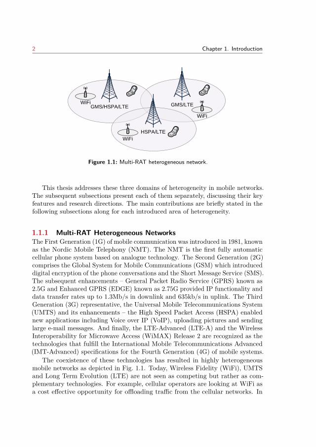
Figure 1.1: Multi-RAT heterogeneous network.
This thesis addresses these three domains of heterogeneity in mobile networks.The subsequent subsections present each of them separately, discussing their keyfeatures and research directions. The main contributions are briefly stated in thefollowing subsections along for each introduced area of heterogeneity.
1.1.1 Multi-RAT Heterogeneous NetworksThe First Generation (1G) of mobile communication was introduced in 1981, knownas the Nordic Mobile Telephony (NMT). The NMT is the first fully automaticcellular phone system based on analogue technology. The Second Generation (2G)comprises the Global System for Mobile Communications (GSM) which introduceddigital encryption of the phone conversations and the Short Message Service (SMS).The subsequent enhancements – General Packet Radio Service (GPRS) known as2.5G and Enhanced GPRS (EDGE) known as 2.75G provided IP functionality anddata transfer rates up to 1.3Mb/s in downlink and 635kb/s in uplink. The ThirdGeneration (3G) representative, the Universal Mobile Telecommunications System(UMTS) and its enhancements – the High Speed Packet Access (HSPA) enablednew applications including Voice over IP (VoIP), uploading pictures and sendinglarge e-mail messages. And finally, the LTE-Advanced (LTE-A) and the WirelessInteroperability for Microwave Access (WiMAX) Release 2 are recognized as thetechnologies that fulfill the International Mobile Telecommunications Advanced(IMT-Advanced) specifications for the Fourth Generation (4G) of mobile systems.
The coexistence of these technologies has resulted in highly heterogeneousmobile networks as depicted in Fig. 1.1. Today, Wireless Fidelity (WiFi), UMTSand Long Term Evolution (LTE) are not seen as competing but rather as com-plementary technologies. For example, cellular operators are looking at WiFi asa cost effective opportunity for offloading traffic from the cellular networks. In
1.1. Background on Heterogeneous Mobile Networks 3
order to provide truly ubiquitous service to the end users, many challenges exist inthe integration of these technologies. In this thesis substantial research has beendone in addressing the challenges in providing a unified framework for networkresource management and achieving performance gains in resource aggregationfrom heterogeneous access nodes.
Interworking Requirements and Architectures
Interworking between different RATs leads to improved overall performance benefitsto the end users as well as to the network operators. The integration betweenRATs can be achieved on different levels, where some requirements [20, 21] may ormay not be fulfilled completely. The main vision is to provide such flexibility thatwill maintain the user’s experience across different access networks, such that thecharging the access to the service is consistent and in accordance with the user’sService Level Agreement (SLA). Furthermore, the service should be provisioned inseamless fashion, meaning that the handover process should have minimal or noimpact to the service quality. Another important aspect is the network selectionprocedure that will enable the user to be attached to a network that providesbetter service at a certain cost (according to user profile).
There are many different approaches in achieving integration between theexisting RATs, each with specific network architecture and support for the abovementioned requirements for interworking which are detailed in [22, 23, 24, 25]. Thetwo most basic levels of coupling are the loose and tight coupling. With the loosecoupling the different access networks are seen as complementary access to theInternet and the services. Installation of new networks is simplified and operatorscan deploy, maintain and perform traffic engineering separately, as there is no needfor high cooperation among networks. Each separate network can utilize differentmechanisms for authentication and billing. The subscriber database can be shared,and Mobile IP [26] can be used as mobility management for handover betweennetworks. On the other hand, with the tight coupling the networks are deployedas alternative RAN. This architecture is more complex as more modificationsare required in the networks - namely WiFi gateways need to implement 3GPPauthentication, mobility management etc. As the non-3GPP networks need toimplement 3GPP mobility management, the tight coupling has better handoverperformance compared to the loose coupling.
The first interworking architectures standardized by 3GPP where the Inter-working WLAN (I-WLAN) [27] and the enhanced Generic Access Network (eGAN)architecture [28, 29]. The I-WLAN is an example of loose coupling, where thestandard Internet Engineering Task Force (IETF) protocols for authentication,accounting and mobility can be used. The GAN technology is an example oftight coupling interworking. The interconnection is achieved through new network
4 Chapter 1. Introduction
element that hides the type of access network towards the core network. Thusthis architecture does not impose any modification to the underlying radio accesstechnology however the terminal needs to be enhanced with the eGAN capability.Interworking among different RAT can be also achieved with IP MultimediaSubsystem (IMS) as it allows for a variety of multimedia services to be extendedover both, fixed and mobile heterogeneous networks. IMS architecture is designedwith the aim of providing ubiquitous cellular access, convergence of services (withstrong accent on IP multimedia services), mobility of users (roaming, handover),support for different levels of QoS and policy-based delivery of services [30].
Since Release 8, the Evolved Packet Core (EPC), as an IP based multi-accesscore network, integrates both 3GPP (GSM, UMTS, LTE) and non-3GPP (includingboth fixed and wireless) access technologies. With the EPC, a user can utilize oneor more access networks to connect to the core network. The 3GPP like accessnetworks are integrated via the Serving Gateway (S-GW). Depending on the trustlevel between the core network operator and the access network operators, differentpoint of integration has been defined. The trusted non-3GGP access technologiesare connected through the Packet Data Network Gateway (P-GW), while theuntrusted are connected through the Evolved Packet Data Gateway (ePDG).
Network Resource Management
Providing an integrated resource management that will enable efficiency in theresource management functionalities over multiple technologies is of crucial impor-tance for both the network operators and end users. The convergence of the existingand emerging technologies requires common framework for control proceduresthat will manage the diverse resources jointly for enhanced user experience.
Several management platforms have been proposed in the literature [31, 32, 33,34, 35, 36]. The concepts proposed by these in the literature deal with enhance-ments for seamless operation, improving the RAT selection schemes and handoverperformance, as well as load balancing. However, the proposed frameworks forRadio Resource Management (RRM) deal with resource diversity coming frommulti -standard technologies. Yet, these management frameworks lack functionali-ties that manage the overall network resources such as optical and computationalresources.
This thesis addresses the above issue by proposing a novel framework fordesign of network resource management that considers other areas of heterogeneityresulting from the evolution of the mobile networks. Furthermore, the frameworkis enhanced with the Self-Organizing Networks (SON) concept and the cognitive
1.1. Background on Heterogeneous Mobile Networks 5
principles, improving the abilities for automation and the learning abilities intothe individual functionalities of the management tasks.
Resource Aggregation
From a user’s point of view, maintaining seamless connection to Wi-Fi networksis not as straightforward as connecting to cellular networks. Often users do notrecognize the available Wi-Fi networks, and, even more, they get discouraged touse Wi-Fi when credentials are necessary to connect to open or public networks.In order to provide a cellular-like experience and the Global Wi-Fi implementation,the Wi-Fi Alliance Hotspot 2.0 Specification, which references the IEEE 802.11uamendment, has been presented [8]. The IEEE 802.11u [9] aims to provide anoverall end-to-end solution for interworking with external networks. It definesLayer 2 transport for a query-response protocol that allows users to effectivelyquery the network for the information relevant to the network selection prior toperforming the authentication procedures.
However, lately more studies are focused on the RAN layer integration betweenLTE and WiFi networks. In this line, the License Assisted Access (LAA) isemerging as a candidate technology for telecommunication companies to utilizeunlicensed spectrum1, particularly the 5GHz band, for wireless data traffic offload-ing [37]. More specifically, the LAA is based on the method of Carrier Aggregation(CA) between a primary cell, operating in licensed spectrum to deliver criticalinformation and guaranteed QoS, and a secondary cell, operating in unlicensedspectrum to opportunistically boost the data rate. Such a coexistence betweenLTE-LAA and WiFi requires fairness as to ensure that the LTE operation willnot impact the existing WiFi users more than an additional WiFi network on thesame carrier [38]. Another type of tight integration can be achieved at the PacketData Convergence Protocol (PDCP) layer from the LTE protocols stack, such thatthe users are simultaneously connected to both, the WiFi and the LTE network.This way, link aggregation is achieved such that the scheduler at the PDCP layerneeds to classify packets into two flows - one with destination characterized bythe LTE access node and the other one characterized by the WiFi access node.
This thesis addresses the challenge of resource aggregation at higher layers,that can be achieved for example at the PDCP layer. This type of aggregation islater referred to as multi-stream aggregation in order to provide the generalizedterm for resource aggregation across heterogeneous access nodes. The motivationfor this study comes form the potential benefits seen in improved data throughputand enhanced quality of experience for the users. The main challenges for such
1license-exempt spectrum.
6 Chapter 1. Introduction
cooperation is the optimal split of the traffic, for which variety of optimizationprocedure can be found [39, 40, 41, 42]. An overview of this methods is provided,and more depth study of the important factors that influence the performanceis provided. Furthermore, a new optimization of the methods for flow controlconsidering additional degree of heterogeneity is proposed.
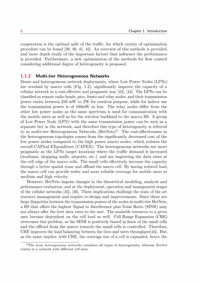
1.1.2 Multi-tier Heterogeneous NetworksDense and heterogeneous network deployments, where Low Power Nodes (LPNs)are overlaid by macro cells (Fig. 1.2), significantly improve the capacity of acellular network in a cost-effective and pragmatic way [43], [44]. The LPNs can beclassified as remote radio heads, pico, femto and relay nodes, and their transmissionpower varies between 250 mW to 2W for outdoor purpose, while for indoor usethe transmission power is of 100mW or less. The relay nodes differ from theother low power nodes as the same spectrum is used for communication withthe mobile users as well as for the wireless backhaul to the macro BS. A groupof Low Power Node (LPN) with the same transmission power can be seen as aseparate tier in the network, and therefore this type of heterogeneity is referredto as multi-tier Heterogeneous Networks (HetNets)2. The cost-effectiveness inthe heterogeneous topologies comes from the significantly decreased cost of thelow power nodes compared to the high power macro nodes, which reduces theoverall CAPital EXpenditure (CAPEX). The heterogeneous networks are morepragmatic as the LPNs target locations where the traffic demand is increased(stadiums, shopping malls, airports, etc.) and are improving the data rates atthe cell edge of the macro cells. The small cells effectively increase the capacitythrough a better spatial reuse and offload the macro cell. By having reduced load,the macro cell can provide wider and more reliable coverage for mobile users atmedium and high velocity.
However, HetNets impose changes in the theoretical modeling, analysis andperformance evaluation, and at the deployment, operation and management stagesof the cellular networks [45], [46]. These implications challenge the state of the artresource management and require re-design and improvements. Since there arelarge disparities between the transmission powers of the nodes in multi-tier HetNets,a BS that offers the highest Signal to Interference plus Noise Ratio (SINR) maynot always offer the best data rates to the user. The available resources to a givenuser become dependent on the cell load as well. Cell Range Expansion (CRE)overcomes this problem, as the SINR is positively biased in favor of the small cellsand the offload from the macro towards the small cells is controlled. Therefore,CRE improves the load balancing between the tiers and users throughput[44]. But,as the name implies, with CRE, the coverage size of a cell is expanded, hence the
2The term heterogeneous networks considers all types of heterogeneity, whereas HetNetrelates to a network with different cell sizes.
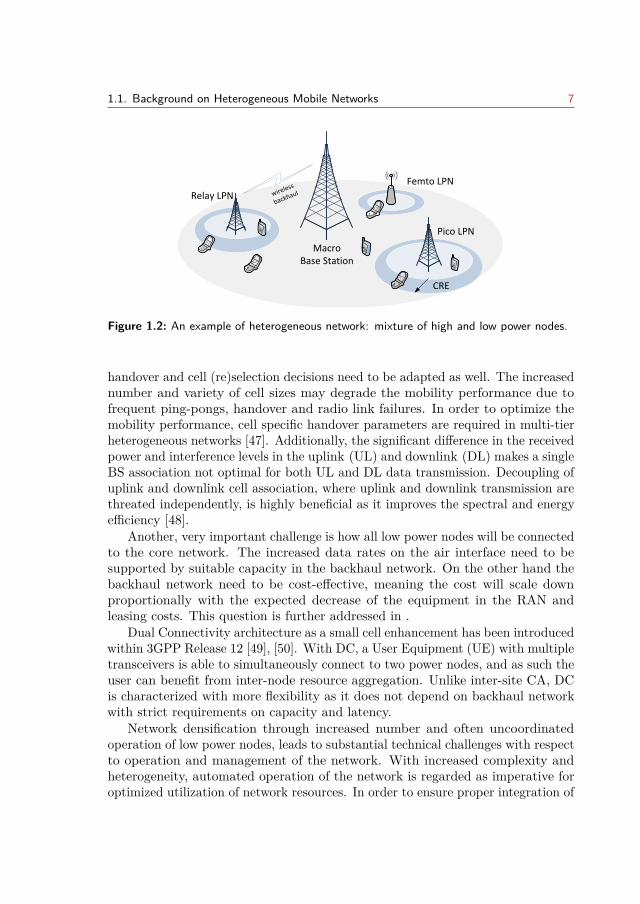
1.1. Background on Heterogeneous Mobile Networks 7
Macro Base Station
CRE
Pico LPN
Femto LPNwireless
backhaulRelay LPN
Figure 1.2: An example of heterogeneous network: mixture of high and low power nodes.
handover and cell (re)selection decisions need to be adapted as well. The increasednumber and variety of cell sizes may degrade the mobility performance due tofrequent ping-pongs, handover and radio link failures. In order to optimize themobility performance, cell specific handover parameters are required in multi-tierheterogeneous networks [47]. Additionally, the significant difference in the receivedpower and interference levels in the uplink (UL) and downlink (DL) makes a singleBS association not optimal for both UL and DL data transmission. Decoupling ofuplink and downlink cell association, where uplink and downlink transmission arethreated independently, is highly beneficial as it improves the spectral and energyefficiency [48].
Another, very important challenge is how all low power nodes will be connectedto the core network. The increased data rates on the air interface need to besupported by suitable capacity in the backhaul network. On the other hand thebackhaul network need to be cost-effective, meaning the cost will scale downproportionally with the expected decrease of the equipment in the RAN andleasing costs. This question is further addressed in .
Dual Connectivity architecture as a small cell enhancement has been introducedwithin 3GPP Release 12 [49], [50]. With DC, a User Equipment (UE) with multipletransceivers is able to simultaneously connect to two power nodes, and as such theuser can benefit from inter-node resource aggregation. Unlike inter-site CA, DCis characterized with more flexibility as it does not depend on backhaul networkwith strict requirements on capacity and latency.
Network densification through increased number and often uncoordinatedoperation of low power nodes, leads to substantial technical challenges with respectto operation and management of the network. With increased complexity andheterogeneity, automated operation of the network is regarded as imperative foroptimized utilization of network resources. In order to ensure proper integration of
8 Chapter 1. Introduction
Pico LPN
Macro Base Station Intra-site
Carrier Aggregation
Inter-site Carrier Aggregation
Component carrier 1
Component carrier 2
Legend:
Figure 1.3: Examples on Carrier Aggregation in heterogeneous network.
automated features into the existing processes and overall architecture for operationand management, the 3GPP has started the standardization of SON use-casesand procedures since Release 8. Such automotive procedures are important forimproving the energy and spectral efficiency in the network, and ensure lowerOPerating EXpenditure (OPEX).
Energy efficiency
Dense deployments of LPN lead to increased overall energy consumption in thenetworks. Green network deployments have become very popular among thetelecommunication industries, not just for cost reduction, but also for reachinggreen environmental targets. As such, network energy efficiency becomes animportant performance indicator for cellular network design. In order to minimizethe energy consumption and CO2 emission, the transmission power and overall op-eration of the nodes needs to be controlled in an automatic way. High fluctuationsin the traffic demand on space and time opens the possibility for adjustment of thetransmission power of the nodes according to the load per area and time, whileensuring proper performance in the networks in terms of coverage and capacity.By placing the nodes into sleep mode (through on/off cycles) when the trafficdemand is notably low, significant gains in energy efficiency can be achieved [51,52, 53].
Spectrum efficiency
In underlay channel deployment strategy of HetNets, the frequency spectrum is
1.1. Background on Heterogeneous Mobile Networks 9
fully reused at each power node. While this strategy provides a better spatialreuse, severe interference can degrade the performance or even create coverageholes. Therefore, advanced interference techniques are required to mitigate bothinter-tier and intra-tier interference. Time-domain enhanced Inter-cell InterferenceCoordination (eICIC) has been standardized in LTE Rel-10 in order to coordinatethe interference between tiers. With eICIC, the interfering cells coordinate trans-mission by configuring subframes with almost no transmission. These subframesare then used by the opposite tier to serve the UEs that have experienced harshinterference conditions. Beside coordinating the transmissions, interference sup-pression can be achieved through Coordinated Multi-Point (CoMP) transmissions.In CoMP, the main idea is to make the interference signal to become useful, whichis achieved such that the nodes within a COMP cluster jointly encode/decodethe data traffic. Additionally, recent techniques for interference rejection at thereceiver have shown improvements by suppressing the interference and mitigatingmultipath fading of the desired signal [54].
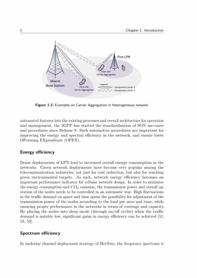
In overlay channel deployments, the low power nodes are deployed on differentcarrier frequency then the macro cell. Each tier becomes homogeneous, andinter-tier interference problem is avoided. While this is beneficial in case of closedfemto cells (nodes with restricted policy for association), it is highly inefficientfrom spectral point of view due to fragmented spectrum. Another possibility is todedicate one carrier frequency for macro coverage, while the other one to be sharedby the macro and small cell tier. An example of such a deployment is illustratedin Fig. 1.3, where Component Carrier (CC) 1 is used by the macro cell, while CC2 is shared. Hence, for terminals that can aggregate the reception of both carriers,the entire spectrum bandwidth becomes available. CA was first introduced inRel-10, to efficiently use fragmented spectrum in order to achieve the data ratesrequired by IMT-Advanced. Afterwards, CA was adopted for non-collocated sites,such as in case of remote radio heads where ideal, high capacity and low latencybackhaul exists. With the introduction of DC architecture for small cells, it wasnatural to extend the inter-site CA for small cells.
One of the goals of this thesis is to study the implications of CA for DC,where the scheduling of radio resources on each CC is independent. The lack ofjoint scheduling raises challenges in the power allocation for uplink transmissions.Analysis of these challenges and enhanced scheme for power allocation is providedin Chapter 3 that takes in consideration the load of the cell and the cell effectiveinterference. The achieved gains by the model have been compared to the resultsfrom other methods [55].
10 Chapter 1. Introduction
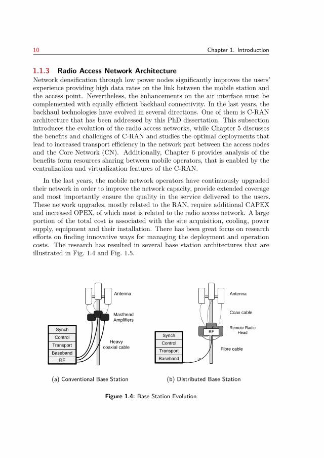
1.1.3 Radio Access Network ArchitectureNetwork densification through low power nodes significantly improves the users’experience providing high data rates on the link between the mobile station andthe access point. Nevertheless, the enhancements on the air interface must becomplemented with equally efficient backhaul connectivity. In the last years, thebackhaul technologies have evolved in several directions. One of them is C-RANarchitecture that has been addressed by this PhD dissertation. This subsectionintroduces the evolution of the radio access networks, while Chapter 5 discussesthe benefits and challenges of C-RAN and studies the optimal deployments thatlead to increased transport efficiency in the network part between the access nodesand the Core Network (CN). Additionally, Chapter 6 provides analysis of thebenefits form resources sharing between mobile operators, that is enabled by thecentralization and virtualization features of the C-RAN.
In the last years, the mobile network operators have continuously upgradedtheir network in order to improve the network capacity, provide extended coverageand most importantly ensure the quality in the service delivered to the users.These network upgrades, mostly related to the RAN, require additional CAPEXand increased OPEX, of which most is related to the radio access network. A largeportion of the total cost is associated with the site acquisition, cooling, powersupply, equipment and their installation. There has been great focus on researchefforts on finding innovative ways for managing the deployment and operationcosts. The research has resulted in several base station architectures that areillustrated in Fig. 1.4 and Fig. 1.5.
Control
Transport
Baseband
RF
Masthead
Amplifiers
Heavy
coaxial cable
Antenna
Synch
(a) Conventional Base Station
Fibre cable
Remote Radio
Head
Antenna
RFSynch
Control
Transport
Baseband
Coax cable
(b) Distributed Base Station
Figure 1.4: Base Station Evolution.
1.1. Background on Heterogeneous Mobile Networks 11
The traditional base station (Fig. 1.4(a)) was mostly utilized for 1st and 2ndgeneration of mobile networks. The main goal of this antenna is to provide widearea coverage, and therefore, the antenna is usually mounted on a mast or arooftop. The antenna is connected to the radio module (hardware related to radioand baseband processing) via coaxial cable. As these cables exhibit high powerlosses, the radio module needs to be located in proximity (few meters). The energyconsumption and the equipment cost related to this design is to high, which makesthe traditional base station unattainable for dense deployments.
In order to reduce the time-to-market, as well as the cost of deployment andoperation, the industry have seen potentials in separating the radio unit andthe baseband processing. This has resulted in a distributed design of the BS,illustrated in Fig. 1.4(b). The radio unit part, in form of Remote Radio Head(RRH), is placed close to the antenna, which alleviates the power dissipation due tothe coaxial cables. The RRH incorporates an amplifier, frequency filter, up/downconverter and performs digital to analogue and analog to digital conversion [56].The baseband digital processing (PHY/MAC) is performed at the BasebandUnit (BBU), while the interconnection to the corresponding RRH is done viaoptical fiber or microwave technology. Several standards have been defined for theinterface between the RRH and the BBU. The most common protocol used for In-phase/Quadrature (IQ) data transmission is the Common Public Radio Interface(CPRI) specified in [57]. The CPRI protocol is bidirectional constant bit rate andimplies very strict synchronization and latency control between the BBU and theRRH. The Open Radio equipment Interface (ORI) protocol complements the CPRIprotocol by specifying the control and management plane [58]. Another protocolthat can be used is the Open Base Station Architecture Initiative (OBSAI) [59].
The functionality performed by the RRH makes it independent on the natureof baseband data that are to be transmitted thus providing support for multi-modecommunications [56]. Beside this advantage, the distributed antenna allows formore flexible deployments as the distance between the RRH and BBU can beextended and the BBU equipment can be located in more feasible place thusallowing reduction in the cost for site rental.
However, with the distributed base station there is still static mapping betweenthe RRHs and the BBUs, and the resource utilization is still inefficient as thedimensioning needs to be done according to peak load. However, as the load atthe cell sites varies across time and space, the BBU resources can be shared amongheavy and less loaded base stations. This is achieved by C-RAN (Fig. 1.5) wherethe BBUs from several cell sites are aggregated at one location which is refereedto as BBU pool. Beside the centralization, another important feature of C-RANis the virtualization/cloudification which allows for general purpose processorsto be utilized for the baseband processing [60]. The statistical multiplexing ofcomputational resources allowed by C-RAN [61], improves the resource utilizationand effectively results in lowering the required infrastructural resources. As such
12 Chapter 1. Introduction
Synch
Control
Transport
Baseband
RRH
Coax
cable
RF
RF
RF
Fibre cable
Antenna
BBU pool
(a) Full centralization
Control
Transport
Baseband
RF
Masthead
Amplifiers
Heavy
coaxial cable
Coaxial cable
Fibre cable
Antenna
BBU poolRemote Radio
Head
Antenna
RFSynch
Control
Transport
Baseband
Coax cable
Synch
Control
Transport
Baseband
RRH
Coax
cableSynch
RF
RF
RF
Fibre cable
Antenna
Synch
Control
Transport
Baseband
RRH
Coax
cable
RF
RF
RF
Fibre cable
Antenna
BB
BB
BB
BBU pool
(b) Split in Baseband Processing
Figure 1.5: C-RAN Architectures.
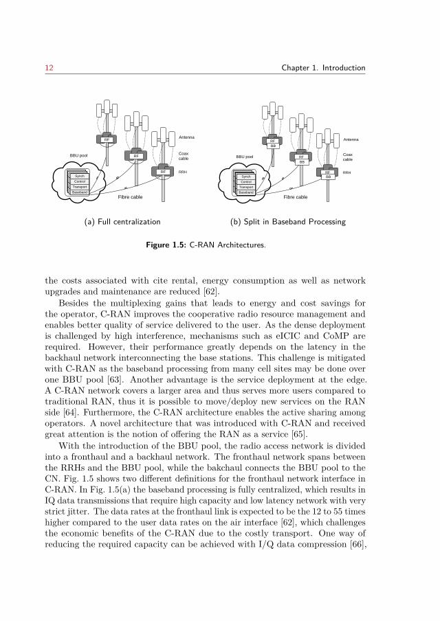
the costs associated with cite rental, energy consumption as well as networkupgrades and maintenance are reduced [62].
Besides the multiplexing gains that leads to energy and cost savings forthe operator, C-RAN improves the cooperative radio resource management andenables better quality of service delivered to the user. As the dense deploymentis challenged by high interference, mechanisms such as eICIC and CoMP arerequired. However, their performance greatly depends on the latency in thebackhaul network interconnecting the base stations. This challenge is mitigatedwith C-RAN as the baseband processing from many cell sites may be done overone BBU pool [63]. Another advantage is the service deployment at the edge.A C-RAN network covers a larger area and thus serves more users compared totraditional RAN, thus it is possible to move/deploy new services on the RANside [64]. Furthermore, the C-RAN architecture enables the active sharing amongoperators. A novel architecture that was introduced with C-RAN and receivedgreat attention is the notion of offering the RAN as a service [65].
With the introduction of the BBU pool, the radio access network is dividedinto a fronthaul and a backhaul network. The fronthaul network spans betweenthe RRHs and the BBU pool, while the bakchaul connects the BBU pool to theCN. Fig. 1.5 shows two different definitions for the fronthaul network interface inC-RAN. In Fig. 1.5(a) the baseband processing is fully centralized, which results inIQ data transmissions that require high capacity and low latency network with verystrict jitter. The data rates at the fronthaul link is expected to be the 12 to 55 timeshigher compared to the user data rates on the air interface [62], which challengesthe economic benefits of the C-RAN due to the costly transport. One way ofreducing the required capacity can be achieved with I/Q data compression [66],
1.2. Thesis Structure 13
however, the data rates still scale with the number of antennas used and isindependent of the user traffic. Recently, different split points in the basebandprocessing have received attention in order to relax the burden on the bandwidth.The idea is illustrated by Fig. 1.5(b) such that only part of the baseband processingis centralized [67, 68, 69]. Each split point designates separate interface definitionand present particular operational impact on CoMP gains, pooling gains as wellas bandwidth and latency requirements [70].
Related to the physical medium used in the RAN, it is important to statethat due to the cost of the fiber and the sometimes infeasible locations of thelow power nodes, placement of fiber cannot always be justified. In such cases,alternative solutions based on wireless technologies become more advantageous.Solutions based on microwave can provide capacity from 10 Mbps-100 Mbps, andeven up to 1 Gbps for short distance (1.5 km) [71]. As the channels betweenlow power nodes and the macro BS is fairly static, wireless backhauling usingmilimeter-wave (mmWave) frequency has received great attention. Several studieshave investigated the feasibility and have shown the benefits of mmWave basedfronthaul [72], [73]. Additionally, massive Multiple Input Multiple Output(MIMO) (both for low and high frequency bands) is another capacity improvementtechniques that can be adopted for wireless backhauling [74].
1.2 Thesis Structure
The overall scope of this thesis is illustrated in Fig. 1.6. This figure presents thecore chapters with their respective area of research as well as the publications thatthese chapters are based on.
This work performed with the PhD study is presented through seven chapters.This chapter provides introduction to the challenges and defines the problemsaddressed in this thesis. Chapter 2 reviews the existing RRM frameworks that havebeen intended for multi-RAT heterogeneous mobile networks. The chapter proposesa novel and universal approach in designing architecture for managing networkresources. The proposed framework takes into consideration the heterogeneity inthe mobile networks in several areas as elaborated in the introductory chapter.It further applies the SON and cognitive principles in order to provide flexibleand effective management over diverse resources such as spectrum, optical andcomputational resources. The control procedures are organized in hierarchicalmanner, achieving the benefits from both the centralized and the distributedapproach for management.
Chapter 3 moves the focus towards the DC architecture for HetNets, wherethe connection between the access nodes is based on traditional backhaul net-works characterized by certain latency. One of the challenges for uplink resourceaggregation in case of dual connectivity is to define the coordinated distribution
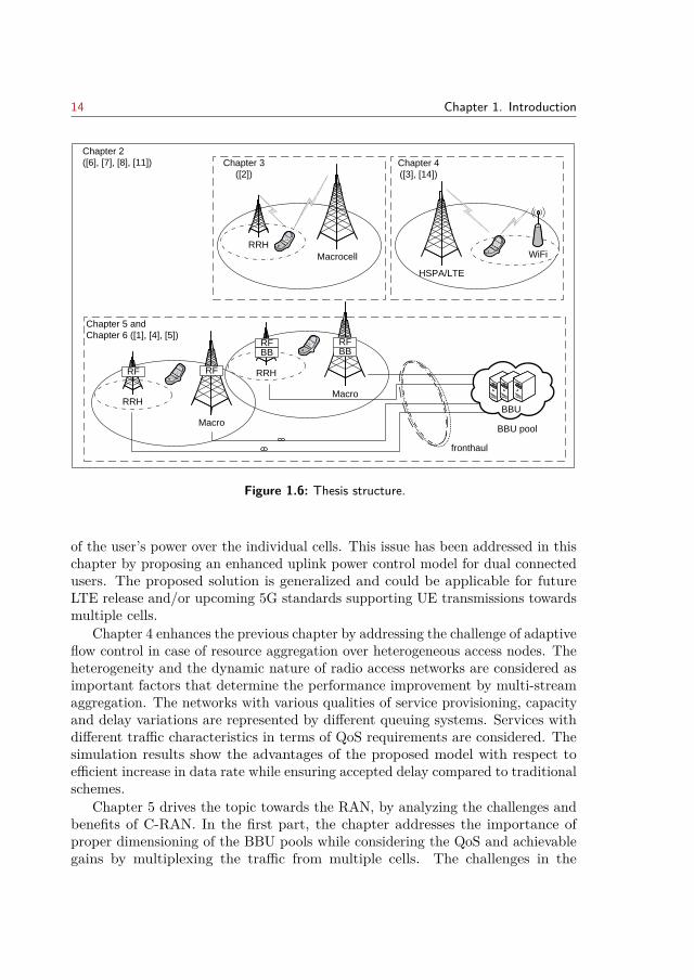
14 Chapter 1. Introduction
Chapter 2
([6], [7], [8], [11])
RRH
Macro
RFRF
BBU pool
fronthaul
Chapter 5 and
Chapter 6 ([1], [4], [5])
RRH
Macro
RFRFBB BB
BBU
RRH
Macrocell
Chapter 3
([2])
WiFi
Chapter 4
([3], [14])
HSPA/LTE
Figure 1.6: Thesis structure.
of the user’s power over the individual cells. This issue has been addressed in thischapter by proposing an enhanced uplink power control model for dual connectedusers. The proposed solution is generalized and could be applicable for futureLTE release and/or upcoming 5G standards supporting UE transmissions towardsmultiple cells.
Chapter 4 enhances the previous chapter by addressing the challenge of adaptiveflow control in case of resource aggregation over heterogeneous access nodes. Theheterogeneity and the dynamic nature of radio access networks are considered asimportant factors that determine the performance improvement by multi-streamaggregation. The networks with various qualities of service provisioning, capacityand delay variations are represented by different queuing systems. Services withdifferent traffic characteristics in terms of QoS requirements are considered. Thesimulation results show the advantages of the proposed model with respect toefficient increase in data rate while ensuring accepted delay compared to traditionalschemes.
Chapter 5 drives the topic towards the RAN, by analyzing the challenges andbenefits of C-RAN. In the first part, the chapter addresses the importance ofproper dimensioning of the BBU pools while considering the QoS and achievablegains by multiplexing the traffic from multiple cells. The challenges in the
1.2. Thesis Structure 15
fronthaul networks in C-RAN are addressed in the second part of the chapter,where the importance in redesigning the baseband processing chain has beenindicated. Heterogeneous networks with cells that are served with differentsplits are evaluated by quantifying the trade-offs between centralization anddecentralization concerning the cost of the pool (gains), fronthaul network capacityand resource utilization.
Chapter 6 analyses networks with dynamic sharing of resources, where it isimportant to carefully design the sharing strategies in order to ensure performancegains in the entire system. Moreover, the effects and implications on each partnerthat enters a sharing agreement need to be analyzed. As such, strategies for activeresource sharing of the radio access network between operators are investigated,identifying the individual benefits depending on the sharing degree.
Finally, Chapter 7 concludes this thesis by summarizing the main results andcontributions of this dissertation. Future research directions are indicated as well.

16
CHAPTER 2Network Resource Management
This chapter discusses the fundamental principles for network resource managementresulting from the evolution of the mobile communication systems. It proposes anovel and universal approach in designing an architecture for managing networkresources. The proposed framework takes into consideration the heterogeneity inthe mobile networks resulting from diverse radio access technologies, cells formedby a range of low powered nodes and base station architecture. The traditionalmobile network features and support for the new advanced multi-cell functionalitiesare included as well.
This chapter is organized as follows. A brief introduction of the problem andgoals of the network resource management is given in Section 2.1. Afterwards, inSection 2.2, the related work is presented where the most relevant cooperativeresource management systems are summarized. Section 2.3 elaborates the pro-posed management framework and demonstrates its flexibility and applicabilityfor resource management in heterogeneous mobile networks. Enhancements tothe proposed framework with the self-optimization and cognitive principles arepresented in Section 2.4, while Section 2.5 describes the internal architectureand the communications of modules. Section 2.6 discusses challenges in the dis-tributed management and provides mechanisms for improved coordination anddecision distribution. The main contributions in this sections are summarized inSection 2.7.
Note: This chapter is based on publication [6], [7], [8] and [14]. The text hasbeen revised and appropriately modified for the purpose of this chapter. A copyrightpermission is enclosed.
2.1 Introduction
An efficient provisioning of services in heterogeneous access network environmentsfor users with multiple access network interfaces and QoS-based applicationsrequires a universal resource management framework that is independent of thedeployed network technologies and architectures. It is also crucial that the net-work resources are intelligently managed and adapted in strong correlation with
17
18 Chapter 2. Network Resource Management
the network capabilities and the particular goals of users, service providers andnetwork operators. Furthermore, the resource management should embrace allphases of mobile network development including planning, deployment, operation,maintenance, migration to new technologies, etc.. As such, the network manage-ment must also optimize the costs that are related to the mobile network andprovide improved revenue to the operators.
The basic radio resource management functionalities are related to call ad-mission and control, power control, spectrum allocation and packet scheduling.However, with the introduction of different access technologies, cells with differentsizes as well as mobile terminals with different capabilities, these rather simplemechanisms became complex, and new mechanisms need to be introduced in orderto avoid congestion and to balance the load over multiple cells, for example. Eachof these RRM functionalities often lead to an NP hard optimization problem, orto an exhaustive search over a large set of possible values for different configu-rations. As such, each of them represents an important research area in mobilecommunication. The cooperation and joint optimization over different technologiesand architecture facilitate the management of the network as an integral entity.Naturally, this leads to improved performance compared to the performance ofeach individual entity.
2.2 Related Work
Most of the existing systems for radio resource management in the literature dealwith only one type of heterogeneity - that is the multi-RAT. Their architectures aredesigned to deal with various access technologies and provide interoperability forenhanced service personalization and transparent communicating environment [31].The specifics of these resource managements differs in the way the resources aremanaged (centralized vs. decentralized) and in the level of coupling between thenetworks.
Integration and cooperation among coexisting multi-RAT is prevalent forseamless connectivity anytime, anywhere, anyhow, while not interrupting theactive sessions. The Media Independent Handover (MIH) (IEEE 802.11) standardstrongly facilitates the handover procedures for transparent handover in heteroge-neous environments. With the MIH an intermediate abstraction layer is designedbetween the Physical (PHY) and the Media Access Control (MAC) layers, thatprovides services to upper layers and helps the handover information flow throughthe entities that take part in the handover. The Reconfigurable Interoperability ofWireless Communications System (RIWCoS) [32] architecture for RRM relies onthe concept of MIH, and it aims at providing highly reconfigurable heterogeneousenvironment.
The Common Radio Resource Management (CRRM) [33] developed within
2.3. Network Management Framework 19
EVEREST project [75] and the Joint Radio Resource Management (JRRM) [34]follow centralized approach for resource management. The centralized way ofresource management provides complete view of resource availability. However,with the increased number of entities, the signaling load becomes excessive andit takes longer time to acquire the relevant information. Thus high latency isintroduced and as such these systems are more difficult to be realized, especiallyfor dense deployed small cells. The CRRM introduces the notion of a pool of radioresources belonging to different RAT that are managed in a common and flexibleway. With the CRRM, different levels of interworking can be defined: low and highdegree. The low level coupling is a policy based, the functionalities of the RRM perRAT remain local, and the centralized CRRM enforces policies definitions acrossthe individual RRM entities. On the other hand with the high degree of coupling,the central server is responsible for RAT selection and handover decisions, in whichcase more frequent exchange of measurements from the terminals and across RATis required.
The JRRM is based on the device capability for multi-homing and servicesplitting across different RAT. As each access technology has its own strengths,multiple simultaneous connections allow for integrations of their benefits. Forexample, increased coverage and reliable communication can be established through3G, while the data rates can be enhanced with WiFi. The central server in theJRRM manages the overall capacity of sub-networks and is responsible for serviceprioritization, splitting and aggregation of the traffic streams. This type ofmanagement allows for joint radio resource scheduling and admission control.
A distributed approach for radio resource management based on multi-agentsis proposed by the Multi-access Radio Resource Management (MRRM) [35]. Theagents cooperate with each other in order to achieve global optimization. Theagents are characterized with cognitive capabilities, for control, adjustments andmonitoring of the assigned radio network and the other agents. Beside cognition,the agents have also a memory layer for intelligent control and fast adjustmentbased on the history of successful configurations. Another architecture for radioresource management that makes use of the cognitive concept was introduced inthe ARAGORN project [36]. With the ARAGON project the different radio accesstechnologies are transparently integrated with the concept of Software DefinedRadio (SDR), making the architecture independent of the specific hardware andradio technology.
2.3 Network Management Framework
With the evolution of the mobile networks, the management of network resourceshas become more complex. The new directions within the mobile network devel-opments, have introduced new challenges for the network management and they
20 Chapter 2. Network Resource Management
MME
GSM/HSPA/LTE
GSM/HSPA/LTE
EPC
WiFi
RRH
RRH
GSM/HSPA/LTE
RF
RFRF
RFBBU
BBU pool
S-GW PDN-GW
Internet
Radio Access
Network
backhaul
fronthaul
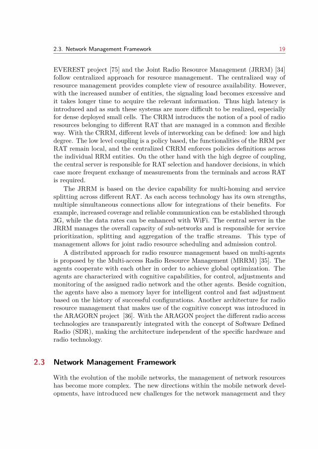
Figure 2.1: Scope of RAN resource management.
can be summarized as following:
• Resource Diversity: spectrum, optical and computational resources. Mostof the resource managements mentioned in the related work consider themanagement of the radio resources on the air interface towards the users.However, as mentioned in Chapter 1 the high data rates on the air interfacemust be supported with sufficient fronthaul/backhaul capacity. Differentmedium and technology can be used for the fronhaul/backhaul network,as such diverse resources are introduced: optical, wireless. Many of thefunctionalities introduced by LTE-A require high-speed signal processing,therefore the computational resources need to be managed in an efficientway. These resources are tightly interconnected and need to be managedjointly in order to ensure the guarantee in the quality of service.
• Functional Challenges: This is related to the introduction of new features inLTE-A such as CoMP, CA, eICIC, DC, and MIMO. These functionalitieshave specific requirements (for example fronhaul/backhaul data rate andlatency), that need to be realized in order to ensure performance gains.
• Architectural/deployment challenges. The introduction of small cells andtheir dense deployments for increased capacity has lead to new transformationin the management of mobile networks. The new architectures in the RANdue to baseband separation, together with virtualization and cloud computinghave resulted in essential changes in the way the mobile networks operate.
With respect to the above challenges, Fig. 2.1 illustrates the scope of theframework for network management proposed in this chapter. This figure indicates

2.3. Network Management Framework 21
Network planning and deployment
BBU dimensioning
New services requirement generation
Mitigation to new technologies
Agreements with network providers
Network maintenance
Activate/deactivate HeNB
BBU/Fronthaul/Backhaul Management
HeNB software updates
Fault Management
Plug&play
Antenna Tilting
Offload (LPN, HeNB, WiFi)
Load balancing, congestion control
Access discovery and selection
Fronthaul fault recovery
BB ressource allocation and assignement
Handover
Scheduling
Power adjustment
Beamforming
Coordinated multi-point transmission and reception
Carrier Aggregation
MIMO operations
Tim
e sc
ale
for
dec
isio
n m
akin
g
Day
s/M
on
ths
Min
ute
s/H
ou
rsSe
con
ds
Mili
seco
nd
s
Figure 2.2: Time scale of management functionalities.
the heterogeneity of the mobile networks due to multiple RAT, multiple tiersresulting from cells with different coverage area as well as backhaul connectivity.The discussed resource management platforms in the previous sections do not fullycover all requirements resulting from such heterogeneity. However, some of theconcepts are still valid and can be included in the new management framework.The advantages of the cognitive agents for local optimization (as in MRRM) aremulti-fold and it is valuable to adopt the concept. Furthermore, the cognitiveprinciples can be adopted on a more global level. SON mechanisms are paramountfor automated management of dense and often uncoordinated deployment of smallcells (such as the case of HeNBs), and as such should be employed in particularRRM functionalities.
2.3.1 Network Management FunctionalitiesFig. 2.2 presents the core functionalities for network management. Depending onthe management task that each of these functionalities is responsible for, the time
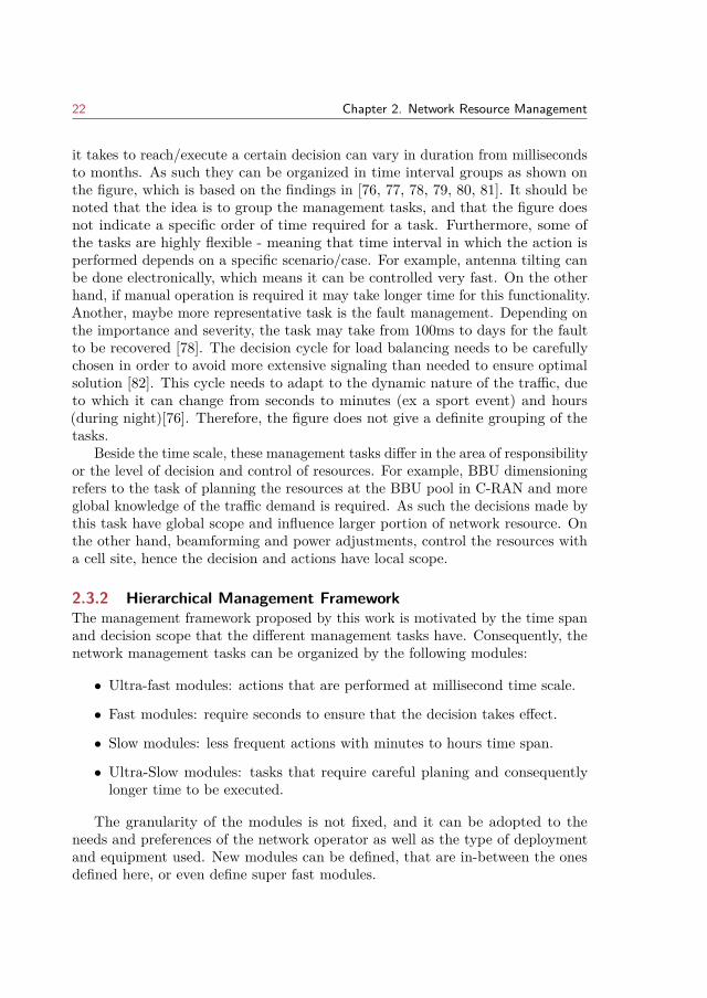
22 Chapter 2. Network Resource Management
it takes to reach/execute a certain decision can vary in duration from millisecondsto months. As such they can be organized in time interval groups as shown onthe figure, which is based on the findings in [76, 77, 78, 79, 80, 81]. It should benoted that the idea is to group the management tasks, and that the figure doesnot indicate a specific order of time required for a task. Furthermore, some ofthe tasks are highly flexible - meaning that time interval in which the action isperformed depends on a specific scenario/case. For example, antenna tilting canbe done electronically, which means it can be controlled very fast. On the otherhand, if manual operation is required it may take longer time for this functionality.Another, maybe more representative task is the fault management. Depending onthe importance and severity, the task may take from 100ms to days for the faultto be recovered [78]. The decision cycle for load balancing needs to be carefullychosen in order to avoid more extensive signaling than needed to ensure optimalsolution [82]. This cycle needs to adapt to the dynamic nature of the traffic, dueto which it can change from seconds to minutes (ex a sport event) and hours(during night)[76]. Therefore, the figure does not give a definite grouping of thetasks.
Beside the time scale, these management tasks differ in the area of responsibilityor the level of decision and control of resources. For example, BBU dimensioningrefers to the task of planning the resources at the BBU pool in C-RAN and moreglobal knowledge of the traffic demand is required. As such the decisions made bythis task have global scope and influence larger portion of network resource. Onthe other hand, beamforming and power adjustments, control the resources witha cell site, hence the decision and actions have local scope.
2.3.2 Hierarchical Management FrameworkThe management framework proposed by this work is motivated by the time spanand decision scope that the different management tasks have. Consequently, thenetwork management tasks can be organized by the following modules:
• Ultra-fast modules: actions that are performed at millisecond time scale.
• Fast modules: require seconds to ensure that the decision takes effect.
• Slow modules: less frequent actions with minutes to hours time span.
• Ultra-Slow modules: tasks that require careful planing and consequentlylonger time to be executed.
The granularity of the modules is not fixed, and it can be adopted to theneeds and preferences of the network operator as well as the type of deploymentand equipment used. New modules can be defined, that are in-between the onesdefined here, or even define super fast modules.
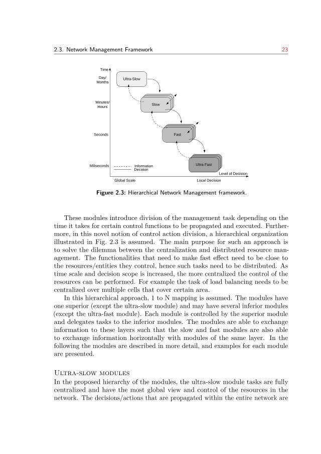
2.3. Network Management Framework 23
Ultra-Slow
Slow
Fast
Ultra Fast
SlowSlow
FastFast
Ultra FastUltra Fast
Level of Decision
Time
Day/
Months
Seconds
Minutes/
Hours
Miliseconds InformationDecision
Global Scale Local Decision
Figure 2.3: Hierarchical Network Management framework.
These modules introduce division of the management task depending on thetime it takes for certain control functions to be propagated and executed. Further-more, in this novel notion of control action division, a hierarchical organizationillustrated in Fig. 2.3 is assumed. The main purpose for such an approach isto solve the dilemma between the centralization and distributed resource man-agement. The functionalities that need to make fast effect need to be close tothe resources/entities they control, hence such tasks need to be distributed. Astime scale and decision scope is increased, the more centralized the control of theresources can be performed. For example the task of load balancing needs to becentralized over multiple cells that cover certain area.
In this hierarchical approach, 1 to N mapping is assumed. The modules haveone superior (except the ultra-slow module) and may have several inferior modules(except the ultra-fast module). Each module is controlled by the superior moduleand delegates tasks to the inferior modules. The modules are able to exchangeinformation to these layers such that the slow and fast modules are also ableto exchange information horizontally with modules of the same layer. In thefollowing the modules are described in more detail, and examples for each moduleare presented.
Ultra-slow modulesIn the proposed hierarchy of the modules, the ultra-slow module tasks are fullycentralized and have the most global view and control of the resources in thenetwork. The decisions/actions that are propagated within the entire network are
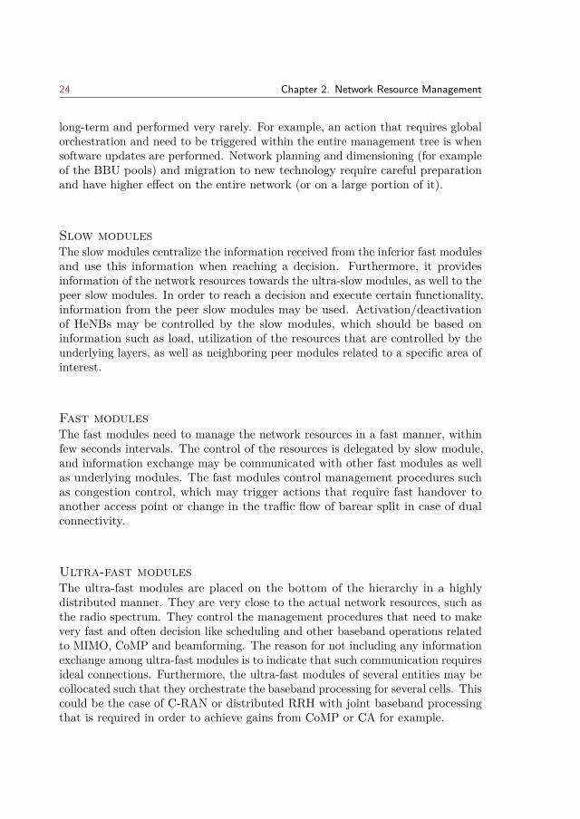
24 Chapter 2. Network Resource Management
long-term and performed very rarely. For example, an action that requires globalorchestration and need to be triggered within the entire management tree is whensoftware updates are performed. Network planning and dimensioning (for exampleof the BBU pools) and migration to new technology require careful preparationand have higher effect on the entire network (or on a large portion of it).
Slow modulesThe slow modules centralize the information received from the inferior fast modulesand use this information when reaching a decision. Furthermore, it providesinformation of the network resources towards the ultra-slow modules, as well to thepeer slow modules. In order to reach a decision and execute certain functionality,information from the peer slow modules may be used. Activation/deactivationof HeNBs may be controlled by the slow modules, which should be based oninformation such as load, utilization of the resources that are controlled by theunderlying layers, as well as neighboring peer modules related to a specific area ofinterest.
Fast modulesThe fast modules need to manage the network resources in a fast manner, withinfew seconds intervals. The control of the resources is delegated by slow module,and information exchange may be communicated with other fast modules as wellas underlying modules. The fast modules control management procedures suchas congestion control, which may trigger actions that require fast handover toanother access point or change in the traffic flow of barear split in case of dualconnectivity.
Ultra-fast modulesThe ultra-fast modules are placed on the bottom of the hierarchy in a highlydistributed manner. They are very close to the actual network resources, such asthe radio spectrum. They control the management procedures that need to makevery fast and often decision like scheduling and other baseband operations relatedto MIMO, CoMP and beamforming. The reason for not including any informationexchange among ultra-fast modules is to indicate that such communication requiresideal connections. Furthermore, the ultra-fast modules of several entities may becollocated such that they orchestrate the baseband processing for several cells. Thiscould be the case of C-RAN or distributed RRH with joint baseband processingthat is required in order to achieve gains from CoMP or CA for example.
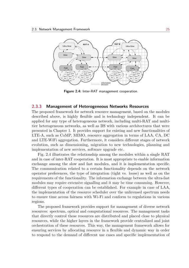
2.3. Network Management Framework 25
RAT A
InformationDecision
Ultra-Slow
SlowSlow
FastFast
RAT BUltra-Slow
Slow
Slow
FastFast
Ultra-fast
Ultra-fast
Ultra-fast
Ultra-fast
Ultra-fast
Ultra-fast
Ultra-fast
Ultra-fast
Ultra-fast
Ultra-fast
Ultra-fast
Ultra-fast
Ultra-fast
Ultra-fast
Ultra-fast
Ultra-fast
Figure 2.4: Inter-RAT management cooperation.
2.3.3 Management of Heterogeneous Networks ResourcesThe proposed framework for network resource management, based on the modulesdescribed above, is highly flexible and is technology independent. It can beapplied for any type of heterogeneous network, including multi-RAT and multi-tier heterogeneous networks, as well as BS with various architectures that werepresented in Chapter 1. It provides support for existing and new functionalities ofLTE-A, such as CoMP, MIMO, resource aggregation in terms of LAA, CA, DCand LTE-WiFi aggregation. Furthermore, it considers different stages of networkevolution, such as dimensioning, migration to new technologies, planning andimplementation of new services, software upgrade etc.
Fig. 2.4 illustrates the relationship among the modules within a single RATand in case of inter-RAT cooperation. It is most appropriate to enable informationexchange among the slow and fast modules, and it is implementation specific.The communication related to a certain functionality depends on the networkoperator preferences, the type of integration (tight vs. loose) as well as on therequirements of the functionality. The information exchange between the ultra-fastmodules may require extensive signalling and it may be time consuming. However,different types of cooperation can be established. For example in case of LAA,the implementation of the resource scheduler over the unlicensed spectrum needsto ensure time access fairness with Wi-Fi and conform to regulations in variousregions.
The proposed framework provides support for management of diverse networkresources: spectrum, optical and computational resources. The management tasksthat directly control these resources are distributed and placed close to physicalresources, while the higher layers in the framework provide centralized and jointorchestration of these resources. This way, the management framework allows forensuring services by allocating resource in a flexible and dynamic way in orderto respond to the demand of different use cases and specific implementation of
26 Chapter 2. Network Resource Management
a service. This demand can be expressed for example in data rate, latency orcoverage. The resources from the higher layers are seen more in logical ratherthan physical instances. This is of great relevance to the future way of buildingand operating networks in order to accommodate various vertical industries. Thisis the main idea behind the concept of logical network slices that will enableoperators to provide networks on an as-a-service basis and meet the wide range ofuse cases [83].
2.4 SON and congnitive aspects
The introduction of self-optimization for automation of the network operationis an advanced and appropriate mechanism to deal with the rising complexityof the mobile networks due to heterogeneity as well as to provide optimizationin the utilization of the diverse network resources [76]. The SON mechanismsare becoming crucial for the mobile operators due to the enormous potentials inminimization of the costs related to network operation and maintenance. SONstandardization was introduced to LTE with Release 8 [84] by defining use casesprocedures and open interfaces in order to ensure interoperability among differentvendors.
The SON use cases are categorized in three distinctive functionalities alongthe operation, administration and maintenance of mobile networks:
• Self-Configuration,
• Self-Optimization, and
• Self-Healing.
These processes can be adopted in the proposed framework for resource manage-ment. The self-configuration and self-healing can be done at the fast and slow level.The specific layer where the actual functionality needs to be implemented dependson its complexity and importance. Self-healing relates to detection of degradation,root cause analysis and compensation. Dealing with cell outage can be detectedfor example, by monitoring system variables and performance indicators, whichcan instantly trigger an action such as increasing the transmission power of asmall cell. On the other hand, self-configuration deals with the auto-configurationof new and existing network elements and automatic cell configuration which hasmore global scope of information and decision spread. Self-optimization is highlybeneficial for the ultra-fast and fast modules, where the resource are managed inmore local manner and the decisions/actions need to be planned and performedimmediately.
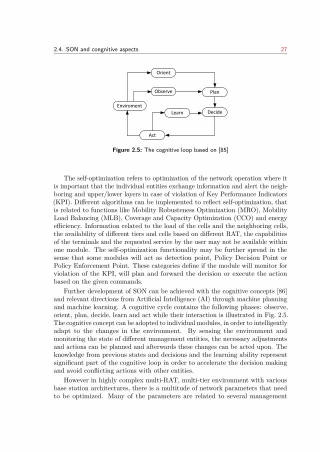
2.4. SON and congnitive aspects 27
Enviroment
Orient
Observe Plan
DecideLearn
Act
Figure 2.5: The cognitive loop based on [85]
The self-optimization refers to optimization of the network operation where itis important that the individual entities exchange information and alert the neigh-boring and upper/lower layers in case of violation of Key Performance Indicators(KPI). Different algorithms can be implemented to reflect self-optimization, thatis related to functions like Mobility Robusteness Optimization (MRO), MobilityLoad Balancing (MLB), Coverage and Capacity Optimization (CCO) and energyefficiency. Information related to the load of the cells and the neighboring cells,the availability of different tiers and cells based on different RAT, the capabilitiesof the terminals and the requested service by the user may not be available withinone module. The self-optimization functionality may be further spread in thesense that some modules will act as detection point, Policy Decision Point orPolicy Enforcement Point. These categories define if the module will monitor forviolation of the KPI, will plan and forward the decision or execute the actionbased on the given commands.
Further development of SON can be achieved with the cognitive concepts [86]and relevant directions from Artificial Intelligence (AI) through machine planningand machine learning. A cognitive cycle contains the following phases: observe,orient, plan, decide, learn and act while their interaction is illustrated in Fig. 2.5.The cognitive concept can be adopted to individual modules, in order to intelligentlyadapt to the changes in the environment. By sensing the environment andmonitoring the state of different management entities, the necessary adjustmentsand actions can be planned and afterwards these changes can be acted upon. Theknowledge from previous states and decisions and the learning ability representsignificant part of the cognitive loop in order to accelerate the decision makingand avoid conflicting actions with other entities.
However in highly complex multi-RAT, multi-tier environment with variousbase station architectures, there is a multitude of network parameters that needto be optimized. Many of the parameters are related to several management
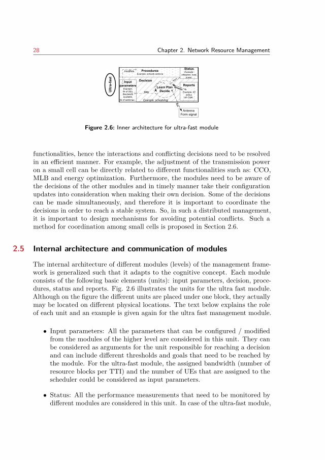
28 Chapter 2. Network Resource Management
Ultr
a-fa
st Decision
Example: scheduling
Input parameters
Example:Nr of UEs,Bandwidth available,
Nr of antennas...
Reports
Example: X2 status,
UE CQR...
Observe
ProceduresExample: activate antenna
StatusExample:
utilization, load, power.
result
AntennaForm signal
Act
Learn PlanDecidedata
modifies
Figure 2.6: Inner architecture for ultra-fast module
functionalities, hence the interactions and conflicting decisions need to be resolvedin an efficient manner. For example, the adjustment of the transmission poweron a small cell can be directly related to different functionalities such as: CCO,MLB and energy optimization. Furthermore, the modules need to be aware ofthe decisions of the other modules and in timely manner take their configurationupdates into consideration when making their own decision. Some of the decisionscan be made simultaneously, and therefore it is important to coordinate thedecisions in order to reach a stable system. So, in such a distributed management,it is important to design mechanisms for avoiding potential conflicts. Such amethod for coordination among small cells is proposed in Section 2.6.
2.5 Internal architecture and communication of modules
The internal architecture of different modules (levels) of the management frame-work is generalized such that it adapts to the cognitive concept. Each moduleconsists of the following basic elements (units): input parameters, decision, proce-dures, status and reports. Fig. 2.6 illustrates the units for the ultra fast module.Although on the figure the different units are placed under one block, they actuallymay be located on different physical locations. The text below explains the roleof each unit and an example is given again for the ultra fast management module.
• Input parameters: All the parameters that can be configured / modifiedfrom the modules of the higher level are considered in this unit. They canbe considered as arguments for the unit responsible for reaching a decisionand can include different thresholds and goals that need to be reached bythe module. For the ultra-fast module, the assigned bandwidth (number ofresource blocks per TTI) and the number of UEs that are assigned to thescheduler could be considered as input parameters.
• Status: All the performance measurements that need to be monitored bydifferent modules are considered in this unit. In case of the ultra-fast module,
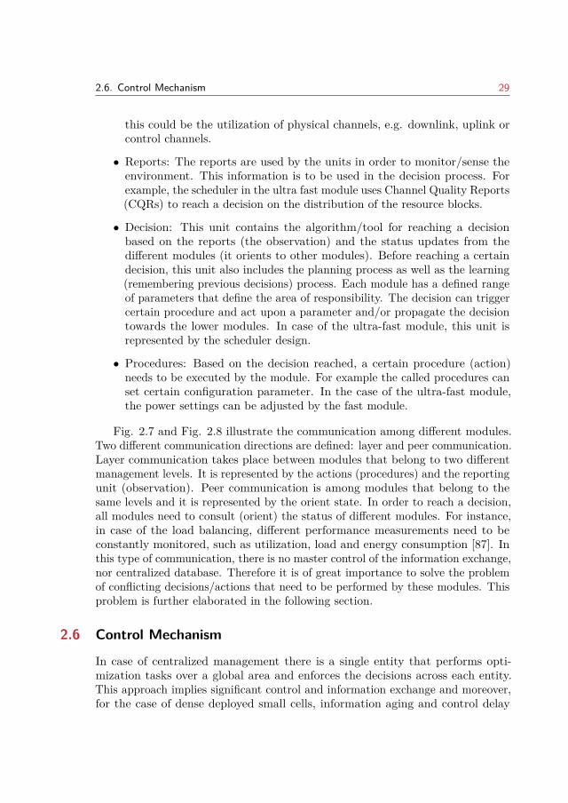
2.6. Control Mechanism 29
this could be the utilization of physical channels, e.g. downlink, uplink orcontrol channels.
• Reports: The reports are used by the units in order to monitor/sense theenvironment. This information is to be used in the decision process. Forexample, the scheduler in the ultra fast module uses Channel Quality Reports(CQRs) to reach a decision on the distribution of the resource blocks.
• Decision: This unit contains the algorithm/tool for reaching a decisionbased on the reports (the observation) and the status updates from thedifferent modules (it orients to other modules). Before reaching a certaindecision, this unit also includes the planning process as well as the learning(remembering previous decisions) process. Each module has a defined rangeof parameters that define the area of responsibility. The decision can triggercertain procedure and act upon a parameter and/or propagate the decisiontowards the lower modules. In case of the ultra-fast module, this unit isrepresented by the scheduler design.
• Procedures: Based on the decision reached, a certain procedure (action)needs to be executed by the module. For example the called procedures canset certain configuration parameter. In the case of the ultra-fast module,the power settings can be adjusted by the fast module.
Fig. 2.7 and Fig. 2.8 illustrate the communication among different modules.Two different communication directions are defined: layer and peer communication.Layer communication takes place between modules that belong to two differentmanagement levels. It is represented by the actions (procedures) and the reportingunit (observation). Peer communication is among modules that belong to thesame levels and it is represented by the orient state. In order to reach a decision,all modules need to consult (orient) the status of different modules. For instance,in case of the load balancing, different performance measurements need to beconstantly monitored, such as utilization, load and energy consumption [87]. Inthis type of communication, there is no master control of the information exchange,nor centralized database. Therefore it is of great importance to solve the problemof conflicting decisions/actions that need to be performed by these modules. Thisproblem is further elaborated in the following section.
2.6 Control Mechanism
In case of centralized management there is a single entity that performs opti-mization tasks over a global area and enforces the decisions across each entity.This approach implies significant control and information exchange and moreover,for the case of dense deployed small cells, information aging and control delay
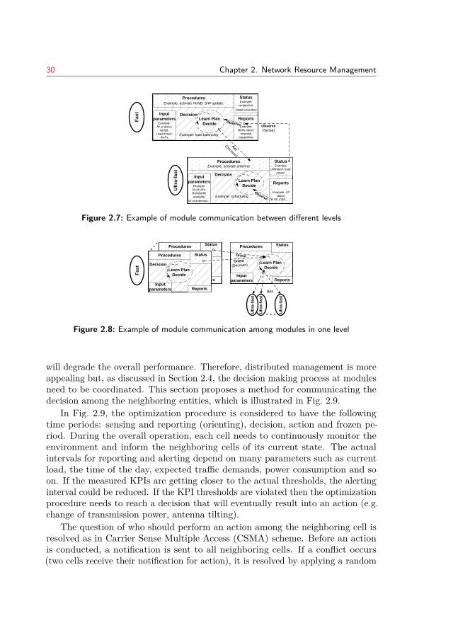
30 Chapter 2. Network Resource Management
Ult
ra-f
as
t
Decision
Example: scheduling
Input
parametersExample:
Nr of UEs,
Bandwidth
available,
Nr of antennas...
Reports
Example: X2
status,
UE CQR...
Observe
ProceduresExample: activate antenna
StatusExample:
utilization, load,
power.
Fa
st
Decision
Example: load balancing
Input
parametersExample:
Nr of active
HeNB,
Load thresh,
RATs
Reports
Example:
faults report,
terminal
capabilities
Procedures
Example: activate HeNB, S/W update.
StatusExample:
congestion,
HeNB utilization
Observe
Act
(Decision)
Observe
(Sense)
Learn Plan
Decide
Learn Plan
Decide
Figure 2.7: Example of module communication between different levels
Fa
st
Decision
Learn Plan
Decide
Input
parameters Reports
ProceduresStatus
Decision
Learn Plan
Decide
Input
parameters Reports
Procedures Status
. . .
Learn Plan
Decide
Input
parameters
Input
parameters Reports
Procedures Status
Orient
Orient
(Decision)
Ult
ra-f
as
t
Ult
ra-f
as
t
Ult
ra-f
as
t
. . .
Learn Plan
Decide
Act
Figure 2.8: Example of module communication among modules in one level
will degrade the overall performance. Therefore, distributed management is moreappealing but, as discussed in Section 2.4, the decision making process at modulesneed to be coordinated. This section proposes a method for communicating thedecision among the neighboring entities, which is illustrated in Fig. 2.9.
In Fig. 2.9, the optimization procedure is considered to have the followingtime periods: sensing and reporting (orienting), decision, action and frozen pe-riod. During the overall operation, each cell needs to continuously monitor theenvironment and inform the neighboring cells of its current state. The actualintervals for reporting and alerting depend on many parameters such as currentload, the time of the day, expected traffic demands, power consumption and soon. If the measured KPIs are getting closer to the actual thresholds, the alertinginterval could be reduced. If the KPI thresholds are violated then the optimizationprocedure needs to reach a decision that will eventually result into an action (e.g.change of transmission power, antenna tilting).
The question of who should perform an action among the neighboring cell isresolved as in Carrier Sense Multiple Access (CSMA) scheme. Before an actionis conducted, a notification is sent to all neighboring cells. If a conflict occurs(two cells receive their notification for action), it is resolved by applying a random
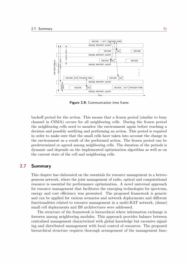
2.7. Summary 31
ACT
FROZEN TIME
SENSE, REPORT, ALERT
DECIDE ACT
Time
DECIDE ACT
DECIDE ACT FROZEN TIME
DECIDE ACT FROZEN TIMEACT
DECIDE
DECIDE
DECIDE
. . .
SENSE, REPORT, ALERT
ACT
SENSE, REPORT, ALERT
SENSE, REPORT, ALERT
SENSE, REPORT, ALERT
rep
ort
s, a
lert
s
rep
ort
s, a
lert
s rep
ort
s, a
lert
s
rep
ort
s,
ale
rts
. . . . . .
Ce
ll S
ON
Ob
jects
DECIDE
DECIDE
Figure 2.9: Communication time frame
backoff period for the action. This means that a frozen period (similar to busychannel in CSMA) occurs for all neighboring cells. During the frozen periodthe neighboring cells need to monitor the environment again before reaching adecision and possibly notifying and performing an action. This period is requiredin order to make sure that the small cells have taken into account the change inthe environment as a result of the performed action. The frozen period can bepredetermined or agreed among neighboring cells. The duration of the periods isdynamic and depends on the implemented optimization algorithm as well as onthe current state of the cell and neighboring cells.
2.7 Summary
This chapter has elaborated on the essentials for resource management in a hetero-geneous network, where the joint management of radio, optical and computationalresource is essential for performance optimization. A novel universal approachfor resource management that facilitates the emerging technologies for spectrum,energy and cost efficiency was presented. The proposed framework is genericand can be applied for various scenarios and network deployments and differentfunctionalities related to resource management in a multi-RAT network, (dense)small cell deployments and BS architectures were addressed.
The structure of the framework is hierarchical where information exchange isforeseen among neighboring modules. This approach provides balance betweencentralized management characterized with global knowledge but excessive signal-ing and distributed management with local control of resources. The proposedhierarchical structure requires thorough arrangement of the management func-
32 Chapter 2. Network Resource Management
tionalities in order to ensure synchronization of the individual decisions and jointmanagement of wireless, optical and computational resources. Each of the individ-ual modules is enhanced with cognitive behavior and learning abilities in orderto assist the decision process and timely adapt to the changes in the network.The communication towards the higher layers allows for establishing global goals,while the communication with the lower and peer layers allows for more generaland detailed knowledge of the system performance. The cognitive concept andthe SON principles augment the proposed framework allowing for more efficientand automated resource management.
CHAPTER 3Uplink Power Control for Dual
Connected UsersThe focus of this chapter is on the implications of dual connectivity architec-ture for HetNets, where the connection between the access nodes is based ontraditional backhaul networks characterized by a certain latency. As the userscan be configured with two radio access nodes, one from the macro cell tier andthe other from the small cell tier, the maximum data rates from the configuredcells can be aggregated. However, as non-ideal backhaul is assumed, the radioresource management at each node is independent which impacts the gains fromresource aggregation. In uplink direction, the maximum power of the user canbe easily exceeded and even more the interference towards the other cells can beincreased. Therefore, one of the challenges for uplink dual connectivity is to definecoordinated distribution of the user’s power over the individual cells. This issuehas been addressed in this chapter by proposing an enhanced uplink power controlmodel for dual connected users with 3GPP Rel-12 LTE dual connectivity as mainreference. The proposed model takes in consideration the load of the cell and thecell effective interference. The solution is generalized and could be applicable forfuture LTE release and/or upcoming 5G standards supporting UE transmissionstowards multiple cells. Furthermore, a criteria for dual connectivity configurationis determined. The performance assessment of the proposed model is done viaadvanced system-level simulations, where important mechanisms that influencethe performance have been accurately modeled. The achieved gains by the modelhave been compared to the results from other methods.
This chapter is organized as follows. Introductory motivation behind this workis presented in Section 3.1. Section 3.2 provides an overview of dual connectivityand the challenges for resource aggregations with this architecture. The traditionpower control for uplink and the implications due to dual configuration are arediscussed in Section 3.3. Section 3.4 elaborates the proposed optimization forusers’ power allocation. Section 3.5 presents the simulation assumptions underwhich the proposed optimization model is evaluated and discusses the obtainedresults. The last section concludes this chapter and remarks future directions.
Note: This chapter is based on publication [2]. The text has been revised andappropriately modified for the purpose of this chapter.
33
34 Chapter 3. Uplink Power Control for Dual Connected Users
3.1 Introduction
HetNets, where low power nodes co-exist with macro BS, have dominant role inaddressing the surge of mobile data traffic increase, the uneven traffic distributionand limited spectrum availability [88]. The low power nodes are characterizedwith smaller size/weight and lower cost of deployment, which make them anattractive solution for fast deployment at hot spot areas both for indoor andoutdoor purpose. Heterogeneous networks with small cells bring many potentialadvantages compared to homogeneous networks. However, as already discussed inChapter 1 there are fundamental and technical issues that need to be addressedin order to fully benefit from such deployments.
As additional spectrum becomes available at higher frequency such as 3.5 GHzand above, frequency separated small cell deployment has received great attentionboth by the wireless industry and research community [89]. Due to the propagationcharacteristics, higher frequency bands are more suitable for small cells, wherethe distance between the small cell node and the users is shorter. Nevertheless,improving per user-throughput by utilizing radio resource at one cell is difficult [90],and resource aggregation over multiple nodes motivates the research towards betterintegration of small cells, especially in case of non-ideal backhaul. In order tobring the interworking between the small cell and macro cell tier closer, and allowfor improved and aggregated resource utilization at both tiers, novel HetNetsarchitecture, known as DC, has been proposed and gained much momentum bythe 3GPP forum.
In dual connectivity the control plane used for connection establishmentand the user (data) plane are separated and may no longer transmitted by thesame physical node. For each user a single control connection is maintainedwhich makes this architecture an attractive solution that meets the challengesrelated to the energy efficiency and mobility robustness. Furthermore, the userplane can be split and transmitted through different nodes, such that the splitcan be dynamically adapted to the radio conditions and load of the multipleconfigured cells. Significant gains in users’ throughput can be achieved by suchinter-node radio resource aggregation. The cell-edge users, for example, canfurther benefit from additional capacity by having multiple transmitting/receivingstreams. While downlink inter-node resource aggregation in DC is supported with3GPP Release 12 [49, 50], there are still technical challenges for supporting uplinkresource aggregation and further studies are required to demonstrate the potentialbenefits. This chapter direct the attention towards this potential by studying thechallenges and requirements for improved uplink data rates. The core topic of thischapter is the uplink power control as it plays a significant role in providing therequired SINR while controlling the interference caused to the surrounding cells.
3.2. Dual Connectivity 35
3.2 Dual Connectivity
Under the assumption of non-ideal backhaul, the dual connectivity provides anarchitecture for higher-layer interworking between macro and small cell tier withthe aim to optimize resource utilization. This type of interworking between themacro and small cell tier allows for distributed deployment and operation of theaccess nodes [91].
The architecture in DC is based on the split concept between the Control (C)-plane and the User (U)-plane and was first introduced to the open literature assoft-cell scheme [92] and Phantom or Macro Assisted (MA) small cell solution [93].Common to both is the fact that the small cell no longer transmits cell specificsignals and channels, while their visibility and connectivity relies on the signalingfrom the macro cell. This way the macro cell becomes responsible for UE channelestablishment and release, while the MA cell transmits UE specific data. A moredetailed proposal for architectural framework for DC is given in [94], and it relieson Channel State Information-reference signals (CSI-RS) to differentiate amongthe small cells and to assist small cell (re)selection procedures.
3.2.1 Dual Connectivity Protocol Architecture
A DC capable UE can be configured with two radio access nodes so that it isable to consume radio resources from both nodes in more efficient manner. Theconcept of DC for a considered scenario by 3GPP is illustrated in Fig. 3.1. Thetwo nodes involved in DC are referred to as Master eNB (MeNB) and SecondaryeNB (SeNB). Multiple serving cells can be associated with each evolved NodeB (eNB) and they are referred to as Master Cell Group (MCG) and SecondaryCell Group (SCG). One primary cell (referred to as PCell from MCG and PSCellfrom SCG) in each group is configured to carry the physical uplink/downlinkcontrol channel and is used for radio link monitoring. The MeNB terminatesthe signaling (S1-MME) interface dedicated for exchange of signaling messagesbetween the Mobility Management Entity (MME) and the eNB. There is onlyone S1-MME per UE, and the Signaling Radio Bearer (SRB) cannot be split oroffloaded to the SeNB. The MeNB becomes responsible for the Control (C)-planeof the UE, such that the Radio Resource Control (RRC) signaling towards theUE required for connection establishment, modification and release is handledby the MeNB (Fig. 3.2). In case of radio link failure towards the SeNB, the UEstops sending and receiving and needs to inform the MeNB via RRC message.The measurement reporting and configuration is also controlled by the MeNB.The SeNB serves to provide additional radio resources in order to improve theuser’s throughput. The coordination between the MeNB and SeNB is done viathe X2-Control (X2-C) interface. This interface is used for SeNB addition, SeNB
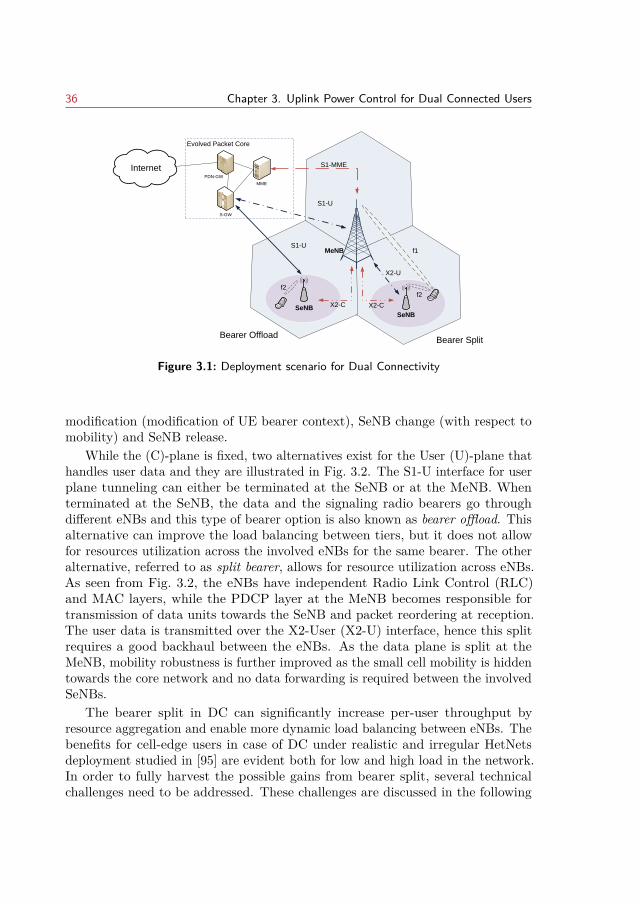
36 Chapter 3. Uplink Power Control for Dual Connected Users
Evolved Packet Core
MeNB
SeNBSeNB
X2-U
S1-MME
S1-U
S1-U
X2-C
f1
f2f2
X2-C
MME
S-GW
Control Interface for SeNB managementSingle RRC connections per UE
Interface for User Data Plane
Bearer SplitBearer Offload
InternetPDN-GW
Figure 3.1: Deployment scenario for Dual Connectivity
modification (modification of UE bearer context), SeNB change (with respect tomobility) and SeNB release.
While the (C)-plane is fixed, two alternatives exist for the User (U)-plane thathandles user data and they are illustrated in Fig. 3.2. The S1-U interface for userplane tunneling can either be terminated at the SeNB or at the MeNB. Whenterminated at the SeNB, the data and the signaling radio bearers go throughdifferent eNBs and this type of bearer option is also known as bearer offload. Thisalternative can improve the load balancing between tiers, but it does not allowfor resources utilization across the involved eNBs for the same bearer. The otheralternative, referred to as split bearer, allows for resource utilization across eNBs.As seen from Fig. 3.2, the eNBs have independent Radio Link Control (RLC)and MAC layers, while the PDCP layer at the MeNB becomes responsible fortransmission of data units towards the SeNB and packet reordering at reception.The user data is transmitted over the X2-User (X2-U) interface, hence this splitrequires a good backhaul between the eNBs. As the data plane is split at theMeNB, mobility robustness is further improved as the small cell mobility is hiddentowards the core network and no data forwarding is required between the involvedSeNBs.
The bearer split in DC can significantly increase per-user throughput byresource aggregation and enable more dynamic load balancing between eNBs. Thebenefits for cell-edge users in case of DC under realistic and irregular HetNetsdeployment studied in [95] are evident both for low and high load in the network.In order to fully harvest the possible gains from bearer split, several technicalchallenges need to be addressed. These challenges are discussed in the following
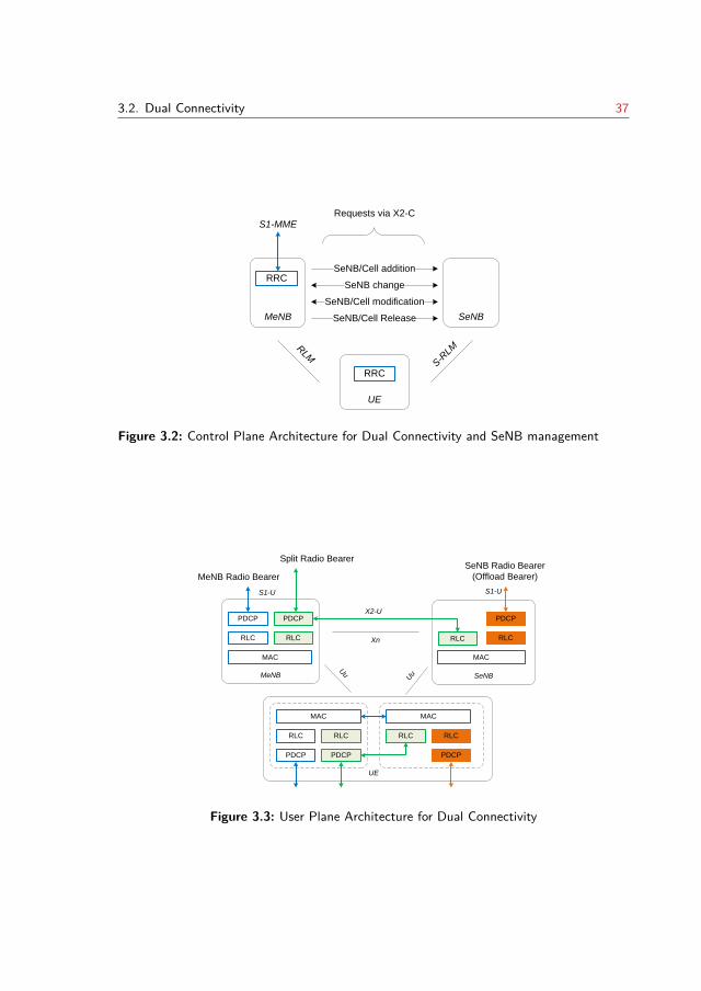
3.2. Dual Connectivity 37
MeNB SeNB
S1-MME
UE
S-R
LMRLM
RRC
RRC
SeNB/Cell addition
SeNB change
SeNB/Cell modification
SeNB/Cell Release
Requests via X2-C
Requests via X2-C
Figure 3.2: Control Plane Architecture for Dual Connectivity and SeNB management
MeNB
PDCP
RLC
MAC
SeNB
PDCP
RLC
S1-U
X2-U
RLC
PDCP
RLC
MAC
MeNB Radio Bearer
SeNB Radio Bearer
(Offload Bearer)
Split Radio Bearer
S1-U
PDCP
RLC
MAC
PDCP
RLCRLC
PDCP
RLC
MAC
UE
Uu
Xn
Uu
Figure 3.3: User Plane Architecture for Dual Connectivity
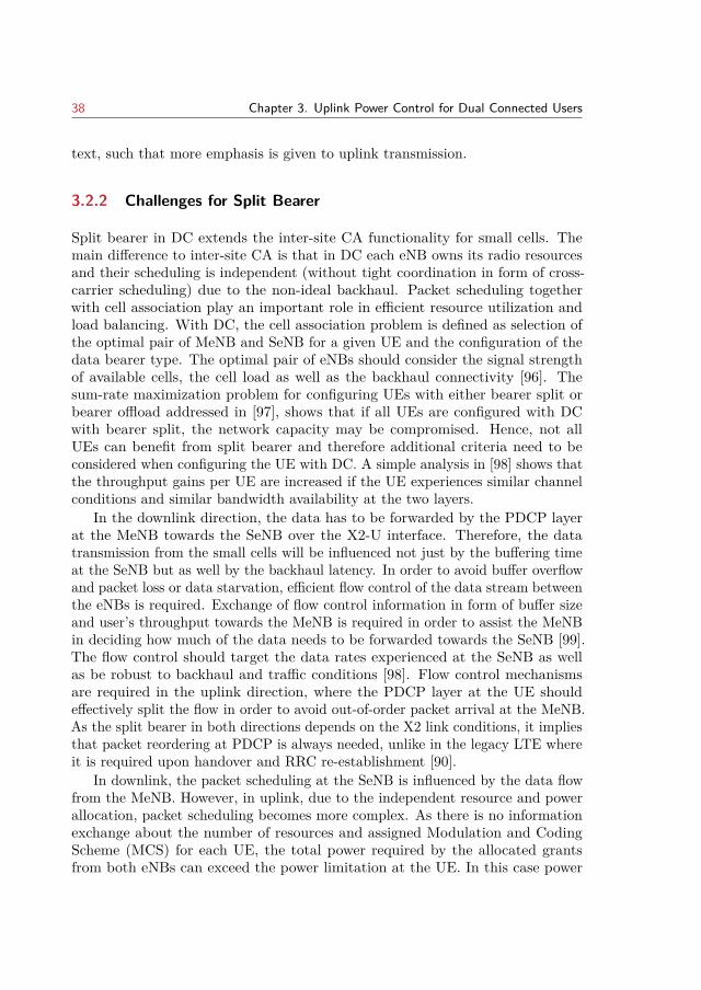
38 Chapter 3. Uplink Power Control for Dual Connected Users
text, such that more emphasis is given to uplink transmission.
3.2.2 Challenges for Split Bearer
Split bearer in DC extends the inter-site CA functionality for small cells. Themain difference to inter-site CA is that in DC each eNB owns its radio resourcesand their scheduling is independent (without tight coordination in form of cross-carrier scheduling) due to the non-ideal backhaul. Packet scheduling togetherwith cell association play an important role in efficient resource utilization andload balancing. With DC, the cell association problem is defined as selection ofthe optimal pair of MeNB and SeNB for a given UE and the configuration of thedata bearer type. The optimal pair of eNBs should consider the signal strengthof available cells, the cell load as well as the backhaul connectivity [96]. Thesum-rate maximization problem for configuring UEs with either bearer split orbearer offload addressed in [97], shows that if all UEs are configured with DCwith bearer split, the network capacity may be compromised. Hence, not allUEs can benefit from split bearer and therefore additional criteria need to beconsidered when configuring the UE with DC. A simple analysis in [98] shows thatthe throughput gains per UE are increased if the UE experiences similar channelconditions and similar bandwidth availability at the two layers.
In the downlink direction, the data has to be forwarded by the PDCP layerat the MeNB towards the SeNB over the X2-U interface. Therefore, the datatransmission from the small cells will be influenced not just by the buffering timeat the SeNB but as well by the backhaul latency. In order to avoid buffer overflowand packet loss or data starvation, efficient flow control of the data stream betweenthe eNBs is required. Exchange of flow control information in form of buffer sizeand user’s throughput towards the MeNB is required in order to assist the MeNBin deciding how much of the data needs to be forwarded towards the SeNB [99].The flow control should target the data rates experienced at the SeNB as wellas be robust to backhaul and traffic conditions [98]. Flow control mechanismsare required in the uplink direction, where the PDCP layer at the UE shouldeffectively split the flow in order to avoid out-of-order packet arrival at the MeNB.As the split bearer in both directions depends on the X2 link conditions, it impliesthat packet reordering at PDCP is always needed, unlike in the legacy LTE whereit is required upon handover and RRC re-establishment [90].
In downlink, the packet scheduling at the SeNB is influenced by the data flowfrom the MeNB. However, in uplink, due to the independent resource and powerallocation, packet scheduling becomes more complex. As there is no informationexchange about the number of resources and assigned Modulation and CodingScheme (MCS) for each UE, the total power required by the allocated grantsfrom both eNBs can exceed the power limitation at the UE. In this case power
3.2. Dual Connectivity 39
scaling would be required, which may lead to lower MCS to be used by the UE,or even cause a drop of UL transmission. The lack of centralized processing forpower allocation can further lead to increased uplink effective interference in eachlayer, nullifying the benefits of dual connectivity. This is investigated in [55] wherethe analysis shows that as the load in the network is increased, the decision forconfiguring users with bearer split should take into consideration the additionalinterference that the user will create towards the secondary cell tier. Power scalingand increased interference lead to decreased spectrum efficiency and in orderto ensure optimal resource utilization, coordination between eNBs is required.Furthermore, a guarantied maximum power used for uplink per eNB should bedetermined.
In traditional eNB, the scheduler derives a scheduling metrics for each UEin order to prioritize among the users. The number of assigned resource blocks(time/frequency pair) is determined by the available power at the UE and theMCS chosen to achieve certain value for the BLock Error Rate (BLER). In orderto ensure benefits from bearer split in uplink at least the following technical issuesshould to be re-thought:
1. Fairness among users. The Proportional Fair (PF) based scheduler designensures fairness among all users within the cell. Hence, users that are locatedat the cell edge will benefit by more frequent resource allocation, in order toachieve the required data rates. However, having a cell-edge user configuredwith bearer split can create imbalance in fairness towards users that arenot configured with bearer split. Therefore, when calculating the schedulingmetric the average user throughput aggregated from all configured cell needsto be considered instead of the users’ per-cell throughput. This means thatit is important that the eNBs exchange information regarding achieved datarate per user.
2. Buffer status reporting. With the bearer split illustrated in Fig. 3.3, theRLC entities at the UE are independent, and therefore the buffer statusin each RLC entity can be reported to the corresponding eNB. However,the complexity in Buffer Status Report (BSR) comes from the fact thatthe PDCP entity is shared. By reporting the full PDPC buffer status toboth eNBs may result in resource allocation that can be wasted, especiallyif the data portion to be transmitted is small. Therefore, a split ratio needto be introduced in BSR for the PDCP layer, such that a virtual status iscreated for each logical link [100]. The split ratio should reflect the channelconditions and the load of the cells in order to improve the load balancingand resource utilization. As the split ratio will influence the amount ofresources allocated per eNB, it is important to consider the backhaul latency
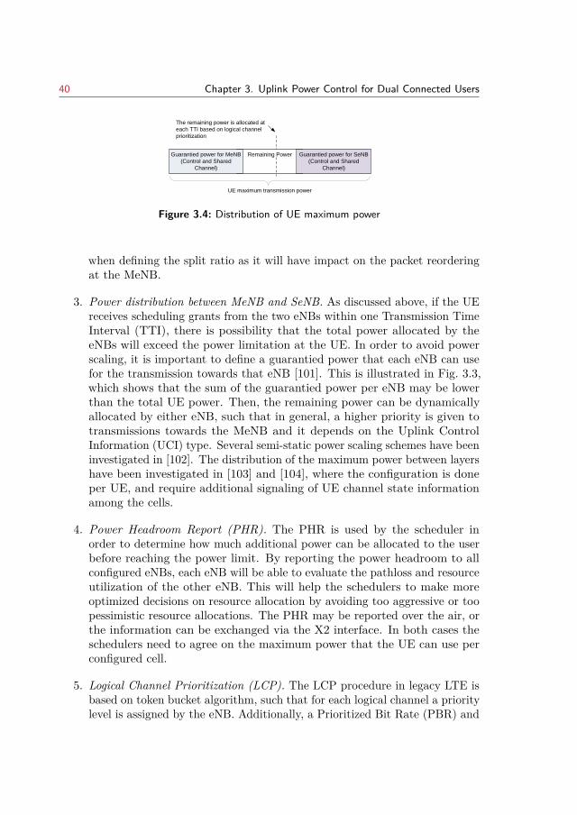
40 Chapter 3. Uplink Power Control for Dual Connected Users
Remaining PowerGuarantied power for MeNB
(Control and Shared
Channel)
Guarantied power for SeNB
(Control and Shared
Channel)
The remaining power is allocated at
each TTI based on logical channel
prioritization
UE maximum transmission power
Figure 3.4: Distribution of UE maximum power
when defining the split ratio as it will have impact on the packet reorderingat the MeNB.
3. Power distribution between MeNB and SeNB. As discussed above, if the UEreceives scheduling grants from the two eNBs within one Transmission TimeInterval (TTI), there is possibility that the total power allocated by theeNBs will exceed the power limitation at the UE. In order to avoid powerscaling, it is important to define a guarantied power that each eNB can usefor the transmission towards that eNB [101]. This is illustrated in Fig. 3.3,which shows that the sum of the guarantied power per eNB may be lowerthan the total UE power. Then, the remaining power can be dynamicallyallocated by either eNB, such that in general, a higher priority is given totransmissions towards the MeNB and it depends on the Uplink ControlInformation (UCI) type. Several semi-static power scaling schemes have beeninvestigated in [102]. The distribution of the maximum power between layershave been investigated in [103] and [104], where the configuration is doneper UE, and require additional signaling of UE channel state informationamong the cells.
4. Power Headroom Report (PHR). The PHR is used by the scheduler inorder to determine how much additional power can be allocated to the userbefore reaching the power limit. By reporting the power headroom to allconfigured eNBs, each eNB will be able to evaluate the pathloss and resourceutilization of the other eNB. This will help the schedulers to make moreoptimized decisions on resource allocation by avoiding too aggressive or toopessimistic resource allocations. The PHR may be reported over the air, orthe information can be exchanged via the X2 interface. In both cases theschedulers need to agree on the maximum power that the UE can use perconfigured cell.
5. Logical Channel Prioritization (LCP). The LCP procedure in legacy LTE isbased on token bucket algorithm, such that for each logical channel a prioritylevel is assigned by the eNB. Additionally, a Prioritized Bit Rate (PBR) and
3.2. Dual Connectivity 41
Bucket Size Duration (BSD)1 are defined in order to avoid starvation of lowerpriority channels and are related to the QoS defined for the bearer. As the(C)-plane is carried over the UE-MeNB link, more control elements will existin this link compared to UE-SeNB link, leading to non-uniform prioritizationfor the same bearer between the two MAC entities. Additionally, if there isonly one PBR defined for the split bearer, it may be enforced twice by thetwo MAC entities, leading to unfair resource scheduling. Hence, the LCPbetween the two MAC entities at the UE need to be in tight coordination.This can be done through a common token bucket, where a single bucket isdefined for the split bearer and the number of tokens that are removed isderived from the sum of the data units generated at both MAC layers. Thesecond option is to define a share of the PBR towards the bucket of eachMAC entity.
6. Sounding Reference Signal (SRS). If the transmit power limit is exceeded,then the power is distributed such that higher priority is given to the MeNBand control channels (for example the Physical Uplink Control Channel(PUCCH) that contains HARQ/ACK has higher priority than PhysicalUplink Shared Channel (PUSCH) without UCI). The lowest priority is givento the SRS [101]. The SRS is used by the eNB to extract the frequencyselective uplink channel quality, which is used by the Link Adaptation (LA)to derive the most appropriate MCS as well as the scheduling in the frequencydomain. Hence, if there is no sufficient power, there are two possibilities:the SRS transmission can either be dropped due to power limitation andscaling avoidance, or different Power Spectral Density (PSD) can be used forSRS and data transmission on PUSCH. Both cases impact the LA, as it mayfail to correctly estimate the channel. An error need to be accounted due tothe difference between estimated SINR based on the uplink SRS strengthmeasurements and the experienced SINR on the data channel.
In this chapter, the main objective is to provide a simplified uplink powerallocation for DC that reduces the information exchange among eNBs, while thegains with respect to achieved user throughput are maximized. The assumptionsfor these technical issues are also elaborated in more details.
3.2.3 Advantages and Considerations in Dual Connectivity Architec-ture
Interworking between the macro cell and small cell tier through DC brings severalother advantages. As the small cell no longer need to transmit acquisition and
1the BSD determines the maximum bucket size of a logical link
42 Chapter 3. Uplink Power Control for Dual Connected Users
reference signals, the energy efficiency in the network can be significantly improvedin conjunction with more dynamic on/off schemes and power transmission adjust-ments. Longer sleep cycles when the small cell is neither sending nor receivingdata bring potential energy efficiency gains in the network [105]. The small cellcan be awaken by the macro cell whenever capacity enhancement and trafficoffload is required. During sleep mode the low power nodes do not transmit anypilot signals, which challenges their discovery by the UEs. A database-aidedconnection procedures is proposed in [106] for this purpose. Additionally, theenergy consumption of the (ideal) backhaul networks can be considered in the cellactivation criteria and offload to the small cells [107].
As the macro cell handles UE connection establishment, modification and re-lease, DC allows for enhanced mobility performance in terms of low probabilities ofexperiencing handover failures or ping-pong events [108]. The mobility robustnesscomes at a cost of increased workload at the macro cell [109]. Although the macrocell hides the small cell mobility towards the CN, signaling between the UE andmacro node in case of addition/removal of secondary cell from the SeNB is stillrequired. In case of dense deployment of small cell, measurements reports from theUEs sent in uplink RRC signaling can cause significant overhead. The overheadbecomes more evident as the velocity of the UE is increased. This issue has beenaddressed in [110] in form of inter-site CA and a solution is proposed such thatthe small cell mobility management is based on UE autonomous decisions with acertain degree of network control.
3.3 Uplink Power Control
3.3.1 Traditional Power Control
The Fractional Power Control (FPC) scheme [111] used for uplink transmissionin LTE has two components: Open Loop Power Control (OLPC) and ClosedLoop Power Control (CLPC). The OLPC serves to compensate the slow varyingpath gain and shadowing. Further optimization of the system performance can beachieved via the CLPC, which provides adjustment of the transmission power inorder to compensate for rapid variations and errors in path loss measurements.
In this work, the focus is on the OLPC, according to which, the power allocationat transmission time t, for UE i associated with cell k in dB scale is defined as:
P ti,k = minPmax,k, P t0,k + 10log10Mti,k + αk · PLti,k (3.1)
In eq. (3.1), P ti,k represent the transmission power at time t for UE i limitedby the maximum power of Pmax,k that can be defined per cell such that Pmax,k ≤Pmax. Mi,k represent the number of Physical Resource Blocks (PRBs) allocatedto the user by cell k.
3.3. Uplink Power Control 43
The parameters that determine the performance of the OLPC [112] are thenormalized power density (P0,k) and path loss compensation factor (αk). Thepurpose of αk, which is a cell specific parameters is to define the fraction of thepath loss that will be compensated. With αk < 1, the transmission power of thecell-edge users is reduced compared to the case of full compensation (αk = 1).This way the OLPC regulates the generated interference to the neighbouring cells.The value of αk should be chosen such that the overall performance in the cell isimproved, while minimizing the impact on the cell coverage.
There are different methods for adjusting the normalized power density, whichcan be user or cell specific parameter. In this work the Load Adaptive Power Con-trol (LAPC) detailed in [113] has been used. The LAPC dynamically adjusts theuser’s power spectral density depending on the bandwidth variations. Accordingto the LAPC, P t0,k is adjusted periodically by the following equation:
P t0,k = Pmax − 10log10Mavgi,k − αk · PL95%,k (3.2)
where Mavgi,k denotes the estimated average number of Physical Resource Block
(PRB)s allocated per UE in cell k, approximated as total number of availablePRBs, divided by the number of UEs served by the cell. In order to ensure minimalpower limitation at the cell edge users, an estimate of the 95%-ile of user pathloss in the cell (PL95%,k) has been considered in eq. (3.2).
3.3.2 Power control for Dual Connectivity with Bearer Split
The power allocation defined by eq. (3.1) and (3.2) is adequate for singleconnections. If the same power allocation is used for UEs that are configuredwith DC with bearer split, the total power allocated at each CC, can exceed themaximum power limitation at the UE. As discussed in Section 3.2, if that happens,power scaling and reduction of the MCS initially set will be required, which leadto reduced spectral efficiency.
Due to the non-ideal backhaul, the RLC and MAC layers at each eNB areindependent. The UEs are configured with independent power control and linkadaptation settings per link, meaning different settings are defined per macro andsmall cell link. Furthermore, the scheduling decision are uncoordinated, meaningthat macro cell scheduler is unaware of the scheduling grants sent by the smallcell, and vice versa. The overall problem can be illustrated with the three examplecases shown in Figure 1:
Case (1): If the UE is only scheduled for transmission towards the small cell in agiven TTI, the optimal transmit power setting and MCS are defined by thesmall cell. The traditional power control defined by eq. (3.1) can be applied.
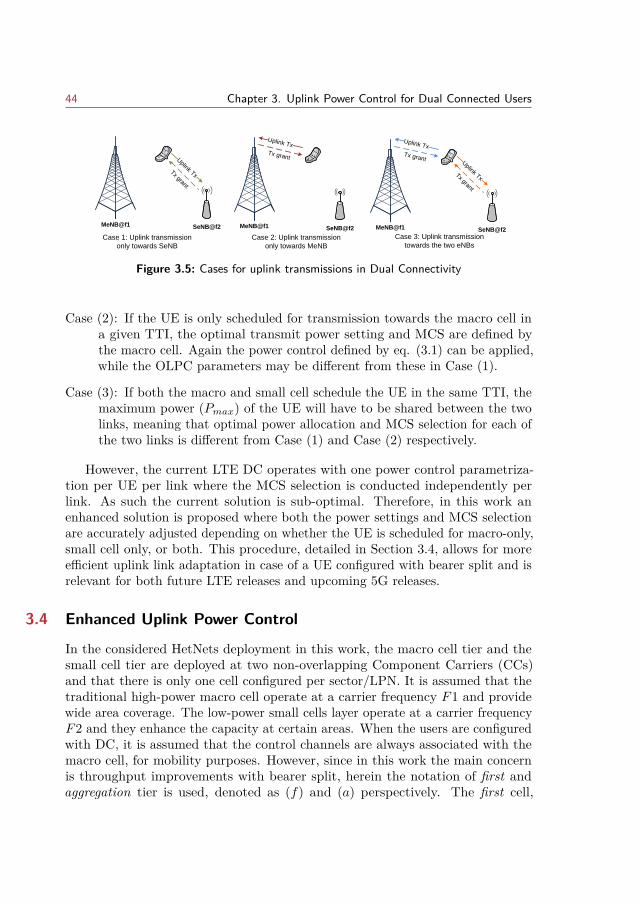
44 Chapter 3. Uplink Power Control for Dual Connected Users
MeNB@f1 SeNB@f2
Uplink Tx
Tx grant
MeNB@f1 SeNB@f2
Uplink Tx
Tx grant
MeNB@f1 SeNB@f2
Uplink Tx
Uplink Tx
Tx grant
Tx grant
Case 1: Uplink transmission
only towards SeNB
Case 2: Uplink transmission
only towards MeNB
Case 3: Uplink transmission
towards the two eNBs
Figure 3.5: Cases for uplink transmissions in Dual Connectivity
Case (2): If the UE is only scheduled for transmission towards the macro cell ina given TTI, the optimal transmit power setting and MCS are defined bythe macro cell. Again the power control defined by eq. (3.1) can be applied,while the OLPC parameters may be different from these in Case (1).
Case (3): If both the macro and small cell schedule the UE in the same TTI, themaximum power (Pmax) of the UE will have to be shared between the twolinks, meaning that optimal power allocation and MCS selection for each ofthe two links is different from Case (1) and Case (2) respectively.
However, the current LTE DC operates with one power control parametriza-tion per UE per link where the MCS selection is conducted independently perlink. As such the current solution is sub-optimal. Therefore, in this work anenhanced solution is proposed where both the power settings and MCS selectionare accurately adjusted depending on whether the UE is scheduled for macro-only,small cell only, or both. This procedure, detailed in Section 3.4, allows for moreefficient uplink link adaptation in case of a UE configured with bearer split and isrelevant for both future LTE releases and upcoming 5G releases.
3.4 Enhanced Uplink Power Control
In the considered HetNets deployment in this work, the macro cell tier and thesmall cell tier are deployed at two non-overlapping Component Carriers (CCs)and that there is only one cell configured per sector/LPN. It is assumed that thetraditional high-power macro cell operate at a carrier frequency F1 and providewide area coverage. The low-power small cells layer operate at a carrier frequencyF2 and they enhance the capacity at certain areas. When the users are configuredwith DC, it is assumed that the control channels are always associated with themacro cell, for mobility purposes. However, since in this work the main concernis throughput improvements with bearer split, herein the notation of first andaggregation tier is used, denoted as (f) and (a) perspectively. The first cell,
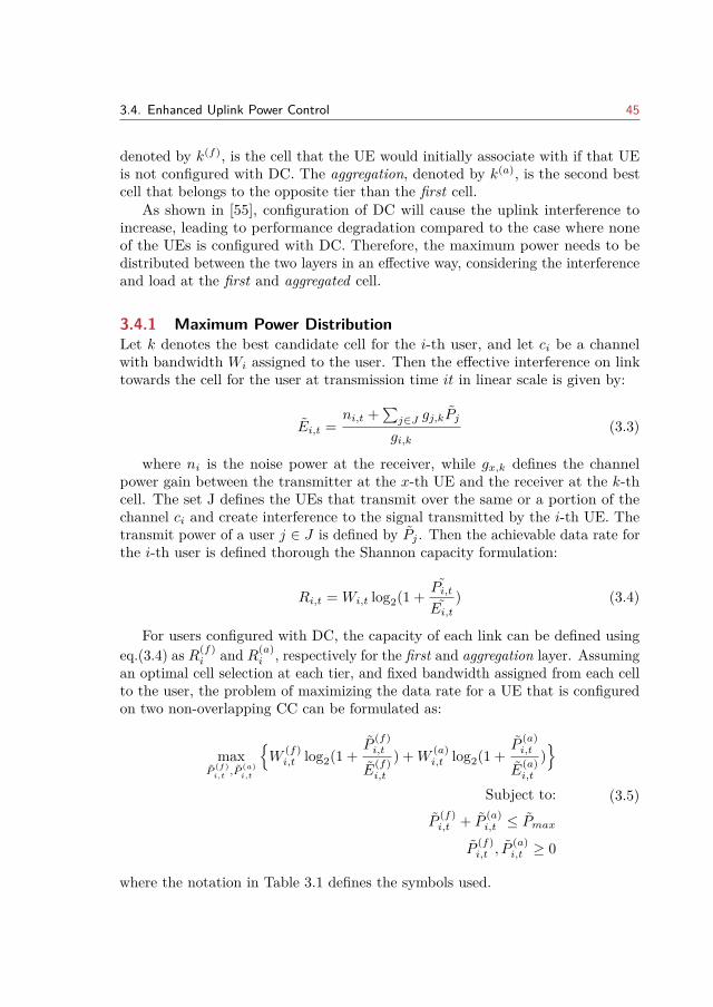
3.4. Enhanced Uplink Power Control 45
denoted by k(f), is the cell that the UE would initially associate with if that UEis not configured with DC. The aggregation, denoted by k(a), is the second bestcell that belongs to the opposite tier than the first cell.
As shown in [55], configuration of DC will cause the uplink interference toincrease, leading to performance degradation compared to the case where noneof the UEs is configured with DC. Therefore, the maximum power needs to bedistributed between the two layers in an effective way, considering the interferenceand load at the first and aggregated cell.
3.4.1 Maximum Power DistributionLet k denotes the best candidate cell for the i-th user, and let ci be a channelwith bandwidth Wi assigned to the user. Then the effective interference on linktowards the cell for the user at transmission time it in linear scale is given by:
Ei,t =ni,t +
∑j∈J gj,kPj
gi,k(3.3)
where ni is the noise power at the receiver, while gx,k defines the channelpower gain between the transmitter at the x-th UE and the receiver at the k-thcell. The set J defines the UEs that transmit over the same or a portion of thechannel ci and create interference to the signal transmitted by the i-th UE. Thetransmit power of a user j ∈ J is defined by Pj . Then the achievable data rate forthe i-th user is defined thorough the Shannon capacity formulation:
Ri,t = Wi,t log2(1 + Pi,t
Ei,t) (3.4)
For users configured with DC, the capacity of each link can be defined usingeq.(3.4) as R(f)
i and R(a)i , respectively for the first and aggregation layer. Assuming
an optimal cell selection at each tier, and fixed bandwidth assigned from each cellto the user, the problem of maximizing the data rate for a UE that is configuredon two non-overlapping CC can be formulated as:
maxP
(f)i,t
,P(a)i,t
W
(f)i,t log2(1 +
P(f)i,t
E(f)i,t
) +W(a)i,t log2(1 +
P(a)i,t
E(a)i,t
)
Subject to:
P(f)i,t + P
(a)i,t ≤ Pmax
P(f)i,t , P
(a)i,t ≥ 0
(3.5)
where the notation in Table 3.1 defines the symbols used.
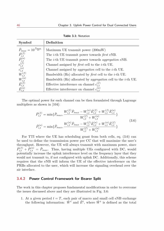
46 Chapter 3. Uplink Power Control for Dual Connected Users
Table 3.1: Notation
Symbol Definition
Pmax = 10Pmax
10 Maximum UE transmit power (200mW)P
(f)i,t The i-th UE transmit power towards first eNB.P
(a)i,t The i-th UE transmit power towards aggregation eNB.c(f)i,t Channel assigned by first cell to the i-th UE.c(a)i,t Channel assigned by aggregation cell to the i-th UE.W
(f)i,t Bandwidth (Hz) allocated by first cell to the i-th UE.
W(a)i,t Bandwidth (Hz) allocated by aggregation cell to the i-th UE.
E(f)i,t Effective interference on channel c(f)
i,t
E(a)i,t Effective interference on channel c(a)
i,t
The optimal power for each channel can be then formulated through Lagrangemultipliers as shown in [104]:
P(f)i,t = minPmax,
W(f)i,t Pmax −W
(a)i,t E
(f)i,t +W
(f)i,t E
(a)i,t
W(f)i,t +W
(a)i,t
P(a)i,t = minPmax,
W(a)i,t Pmax −W
(f)i,t E
(a)i,t +W
(a)i,t E
(f)i,t
W(f)i,t +W
(a)i,t
(3.6)
For TTI where the UE has scheduling grant from both cells, eq. (3.6) canbe used to define the transmission power per CC that will maximize the user’sthroughput. However, the UE will always transmit with maximum power, sinceP
(f)i,t + P
(a)i,t = Pmax. Thus, having multiple UEs configured with DC, would
potentially increase the uplink interference level on the frequency layer that theywould not transmit to, if not configured with uplink DC. Additionally, this schemerequires that the eNB will inform the UE of the effective interference on thePRBs allocated to the user, which will increase the signaling overhead over theair interface.
3.4.2 Power Control Framework for Bearer Split
The work in this chapter proposes fundamental modifications in order to overcomethe issues discussed above and they are illustrated in Fig. 3.6:
1. At a given period t = T , each pair of macro and small cell eNB exchangethe following information: W t and Et, where W t is defined as the total
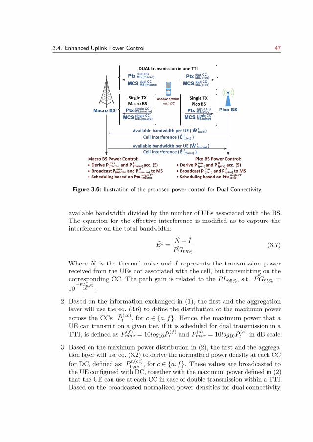
3.4. Enhanced Uplink Power Control 47
Pico BSSiteMacro BS
Mobile Station with DC
Ptx MS,(pico)Ptx single CCPtx MS,(macro)Ptx
single CC
MCS MS,(pico)MCS single CC
MCS MS,(macro)MCS single CC
Ptx dual CC
Ptx MS,(macro)
MCS dual CC
MCS MS,(pico)
W (pico))Available bandwidth per UE ( Ŵ t
Available bandwidth per UE (W (macro) )Ŵ t
Ê t Cell Interference ( Ê (pico) )
Ê tCell Interference ( Ê (macro) )
· Derive P max and P 0 acc. (5)· Broadcast P max and P 0 to MS· Scheduling based on Ptx single CC
P (macro)
P(macro)
P(macro)
P (macro)
Ptx (macro)
P (pico)
P (pico)
P (pico)
P (pico)
Ptx (pico)
· Derive P max and P 0 acc. (5)· Broadcast P max and P 0 to MS· Scheduling based on Ptx single CC
Macro BS Power Control: Pico BS Power Control:
Ptx dual CCPtx MS,(pico)
MCS dual CC
MCS MS,(macro)
DUAL transmission in one TTI
Single TX Macro BS
Single TX Pico BS
Figure 3.6: Ilustration of the proposed power control for Dual Connectivity
available bandwidth divided by the number of UEs associated with the BS.The equation for the effective interference is modified as to capture theinterference on the total bandwidth:
Et = N + I
PG95%(3.7)
Where N is the thermal noise and I represents the transmission powerreceived from the UEs not associated with the cell, but transmitting on thecorresponding CC. The path gain is related to the PL95%, s.t. PG95% =10−PL95%
10 .
2. Based on the information exchanged in (1), the first and the aggregationlayer will use the eq. (3.6) to define the distribution ot the maximum poweracross the CCs: P (cc)
t , for c ∈ a, f. Hence, the maximum power that aUE can transmit on a given tier, if it is scheduled for dual transmission in aTTI, is defined as P (f)
max = 10log10P(f)t and P (a)
max = 10log10P(a)t in dB scale.
3. Based on the maximum power distribution in (2), the first and the aggrega-tion layer will use eq. (3.2) to derive the normalized power density at each CCfor DC, defined as: P t,(cc)0,dc , for c ∈ a, f. These values are broadcasted tothe UE configured with DC, together with the maximum power defined in (2)that the UE can use at each CC in case of double transmission within a TTI.Based on the broadcasted normalized power densities for dual connectivity,
48 Chapter 3. Uplink Power Control for Dual Connected Users
the i-th UE will be able to derive the transmission power P t,(cc)i,dc , cc ∈ a, f,using eq. (3.1).
4. The derivation of the P (cc)max and P t,(cc)0,dc , for cc ∈ a, f is performed at each
eNB, for a defined pair of a macro and a small cell. This means that thedistribution of the maximum UE transmission power will depend to whichpair of macro and small cell the UE is associated with. For example a UEthat is associated with Macro Cell 1 and Small Cell 1, may not have thesame P (f)
max and P (a)max as the UE that is associated to Macro Cell 1 and Small
Cell 2. Each UE configured with DC will have four values of P0: P t,(cc)0,dc , forcc ∈ a, f used by the UE when scheduled in one TTI by both layers, andP t0,k, for k ∈ m, s when the UE is scheduled by one eNB (macro or smallcell ) at a given TTI.
The fundamental idea is that each UE maintains two pairs of transmissionpower and MCS as indicated in Fig. 3.6. The network configures the UE withdifferent uplink transmit power control settings: one for transmission towardsthe macro only, one for transmission towards the small cell only, and individualconfiguration for each cell in case of simultaneous transmission towards the macroand small cell in the same TTI. In each TTI, the UE checks if it has receivedscheduling grant at both configured CCs. If there is only one scheduling granton a CC (cc), the UE will use power P ti,k=(cc) and MCS corresponding to a givenBLER target. If there are two scheduling grants, then the UE will use the dualtransmission power towards each CC, defined as P t,(cc)i,dc and corresponding MCS.As such, the scheduling grants that are sent from the eNBs should contain twoMCS suggestions: one for single transmission and one for dual transmission. Asthe macro and small cell does not know on an instantaneous basis if the UE isscheduled from both cells, the uplink UE transmission could include a headerto indicate the used MCS. The solution could also work without such a header,and instead rely on blind MCS detection between the MCS for single and dualtransmission.
3.4.3 Dual Connectivity ConfigurationThe UEs configured with uplink DC, have an additional limitation of the maximumUE transmission power due to increased peak-to-average power ratio (PAPR) andinter-modulation effects in case of bandwidth aggregation across non-contiguouscarriers [114]. The effect is modelled by power back-off (Pbackoff ) such that themaximum power reduction mask equation by 3GPP [115] is used to determinean upper bound of the required power back-off. The value of Pbackoff (in dB) isdetermined based on the allocated and the available bandwidth aggregated fromthe CCs. The exact procedure is further detailed in [116]. As such for a UE to be
3.5. Performance Analysis 49
configured with DC, the following power limitation checks can be defined:
P t,dc(a) ≤ Pmax
10log10(10Pt,(f)i,dc
/10 + 10Pt,(a)i,dc
/10) ≤ (Pmax − Pbackoff )(3.8)
This limitation will not configure with DC the UEs that are very far from theaggregation layer, since these UEs could increase the uplink interference on theaggregation layer, especially when being scheduled only by the aggregation cell ina given TTI. Additionally, by having the power limit for dual transmissions ontwo CCs, the need for power scaling will be avoided.
3.5 Performance Analysis
A system level simulator has been used to evaluate the performance of the proposedpower control. The evaluation guidelines for heterogeneous networks provided by3GPP in [117] have been followed. LTE specifications has been followed as well,and major radio resource management functionalities like packet scheduling, linkadaptation, Hybrid ARQ (HARQ), power control etc. have been included. Thealgorithms used and the main parameters are summarized in Table 3.2.
The simulated network topology consists of seven regular 3-sector hexagonalmacro sites, and 4 small cells randomly dropped per macro sector area accordingto spatial uniform point process. Two CC are configured, each with 10 MHzbandwidth. The macro cell are deployed with CC at 1.8 GHz carrier frequency,while the small cells are deployed with CC at 2.6 GHz carrier frequency. Twoseparate transceivers are assumed at each UE, in order to be configured withtwo CC simultaneously. The user distribution over the simulation area assumeshotspot dropping, such that 2/3 of the total UEs have been dropped uniformlywithin 40m radius to the center of the small cells, while the remaining UEs havebeen uniformly placed within the entire simulation area. The applied traffic modelis finite buffer with fixed payload size. The calls arrive according to Poissondistribution with intensity of λ calls per second at each macro sector area, whilethe call is terminated when the total buffer is successfully transmitted. Theproduct of the call arrival rate and payload size defines the offered load per macrosector area.
3.5.1 Simulation AssumptionAs already discussed previously, there are several technical challenges that need tobe considered for DC with bearer split. This works threats the problem of powerdistribution, while for the other challenges the following assumptions have beenconsidered.
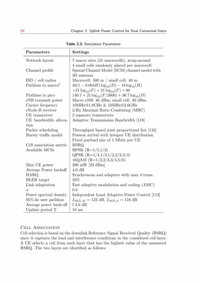
50 Chapter 3. Uplink Power Control for Dual Connected Users
Table 3.2: Simulation Parameters
Parameters Settings
Network layout 7 macro sites (21 macrocells), wrap-around4 small cells randomly placed per macrocell
Channel profile Spatial Channel Model (SCM) channel model with3D antenna
ISD / cell radius Macrocell: 500 m / small cell: 40 mPathloss to macro2 40(1− 0.004H) log10(D)− 18 log10(H)
+21 log10(F ) + 21 log10(F ) + 80Pathloss to pico 140.7 + 21 log10(F/2000) + 36.7 log10(D)eNB transmit power Macro eNB: 46 dBm; small cell: 30 dBmCarrier frequency [email protected] & [email protected] receiver 2-Rx Maximal Ratio Combining (MRC)UE transceiver 2 separate transceiversUE bandwidth alloca-tion
Adaptive Transmission Bandwidth [118]
Packet scheduling Throughput based joint proportional fair [116]Bursty traffic model Poisson arrival with hotspot UE distribution
Fixed payload size of 1 Mbits per UECell association metric RSRQAvailable MCSs BPSK (R=1/5,1/3)
QPSK (R=1/4,1/3,1/2,2/3,3/4)16QAM (R=1/2,2/3,3/4,5/6)
Max UE power 200 mW [23 dBm]Average Power backoff 4.0 dBHARQ Synchronous and adaptive with max 4 trans.BLER target 20%Link adaptation Fast adaptive modulation and coding (AMC)α 0.8Power spectral density Independent Load Adaptive Power Control [113]95%-ile user pathloss L95%,M = 123 dB, L95%,S = 116 dBAverage power back-off f 4.0 dBUpdate period T 10 ms
Cell AssociationCell selection is based on the downlink Reference Signal Received Quality (RSRQ)since it captures the load and interference conditions in the considered cell-layer.A UE selects a cell from each layer that has the highest value of the measuredRSRQ. The two layers are identified as follows:
3.5. Performance Analysis 51
k(f) = argmaxk
maxk∈MRSRQk,max
k∈SRSRQk +REk
k(a) = argmin
k
maxk∈MRSRQk,max
k∈SRSRQk +REk
(3.9)
where REk is the range extension offset applied to the small cell for load balancingpurposes.
MAC SchedulingDC is intended for deployment where ideal backhaul connectivity is not present.Due to absence of tight scheduling synchronization between the macro and smallcell layer, independent radio resource allocation at the MAC is performed at eachcell. This means that first layer will not be aware if the aggregation layer hasscheduled the UE within the same TTI and wise versa. In this work, PF MACscheduling based on adaptive transmission bandwidth as proposed in [118] isimplemented at each cell. In order to ensure fairness of the UE across the layers,joint PF scheduling defined in [116] is used. In the joint scheduling, the sum of theaverage scheduled throughput over all CCs at which the UE has been scheduled isconsidered when calculating the PF metric. This means that on a certain periodof time, the MAC schedulers exchange information on the average UE throughput.
Link AdaptationIndependent MCS adaptation is performed by the MAC entity at each eNB inorder to match the quality of the two links. The link adaptation determines themost suitable MCS based on frequency selective channel state information suchthat a certain BLER target is achieved. An outer loop link adaptation algorithmdescribed in [119] is used in order to compensate measurement errors. In this work,for each DC configured UE, at both eNBs, there are two separate link adaptation,one for single and the other for dual transmission. This is needed in order todetermine the most appropriate MCS for both cases when the user is scheduled bya single eNB or by both eNBs at the same TTI. As discussed previously, the linkadaptation unit require that the UEs transmit SRS over the whole or a fractionof the scheduling bandwidth such that the power spectral density used for SRSis the same as the power spectral density used for data transmissions. With theproposed mechanisms in this work, the UEs need to send SRSs for both single anddual transmissions. However, due to UE power capabilities, there can be limit onthe sounding bandwidth or the power spectral density used for the SRS. Howeverin this work, power limitations for the SRS are not taken into account.
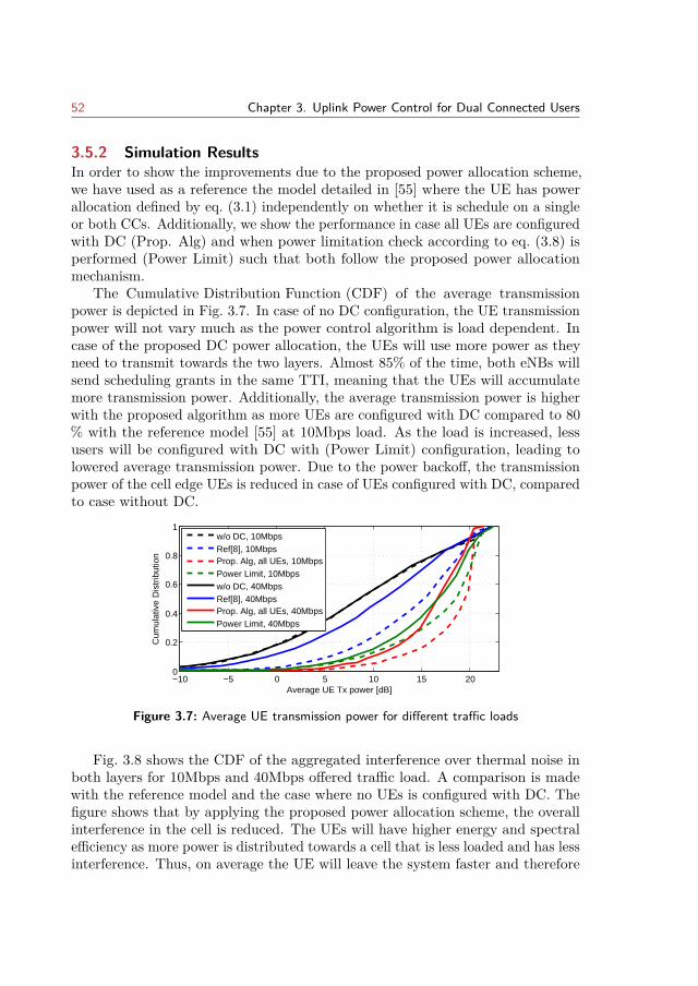
52 Chapter 3. Uplink Power Control for Dual Connected Users
3.5.2 Simulation ResultsIn order to show the improvements due to the proposed power allocation scheme,we have used as a reference the model detailed in [55] where the UE has powerallocation defined by eq. (3.1) independently on whether it is schedule on a singleor both CCs. Additionally, we show the performance in case all UEs are configuredwith DC (Prop. Alg) and when power limitation check according to eq. (3.8) isperformed (Power Limit) such that both follow the proposed power allocationmechanism.
The Cumulative Distribution Function (CDF) of the average transmissionpower is depicted in Fig. 3.7. In case of no DC configuration, the UE transmissionpower will not vary much as the power control algorithm is load dependent. Incase of the proposed DC power allocation, the UEs will use more power as theyneed to transmit towards the two layers. Almost 85% of the time, both eNBs willsend scheduling grants in the same TTI, meaning that the UEs will accumulatemore transmission power. Additionally, the average transmission power is higherwith the proposed algorithm as more UEs are configured with DC compared to 80% with the reference model [55] at 10Mbps load. As the load is increased, lessusers will be configured with DC with (Power Limit) configuration, leading tolowered average transmission power. Due to the power backoff, the transmissionpower of the cell edge UEs is reduced in case of UEs configured with DC, comparedto case without DC.
−10 −5 0 5 10 15 200
0.2
0.4
0.6
0.8
1
Average UE Tx power [dB]
Cum
ulat
ive
Dis
trib
utio
n
w/o DC, 10MbpsRef[8], 10MbpsProp. Alg, all UEs, 10MbpsPower Limit, 10Mbpsw/o DC, 40MbpsRef[8], 40MbpsProp. Alg, all UEs, 40MbpsPower Limit, 40Mbps
Figure 3.7: Average UE transmission power for different traffic loads
Fig. 3.8 shows the CDF of the aggregated interference over thermal noise inboth layers for 10Mbps and 40Mbps offered traffic load. A comparison is madewith the reference model and the case where no UEs is configured with DC. Thefigure shows that by applying the proposed power allocation scheme, the overallinterference in the cell is reduced. The UEs will have higher energy and spectralefficiency as more power is distributed towards a cell that is less loaded and has lessinterference. Thus, on average the UE will leave the system faster and therefore
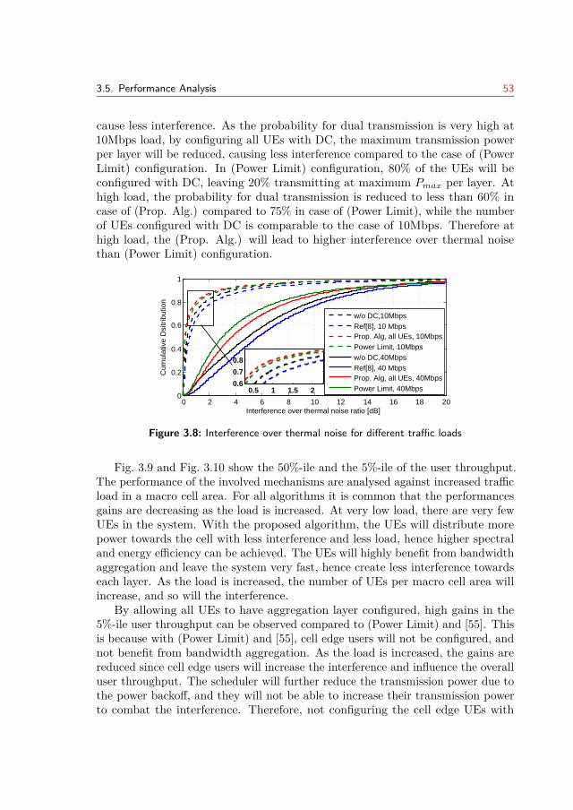
3.5. Performance Analysis 53
cause less interference. As the probability for dual transmission is very high at10Mbps load, by configuring all UEs with DC, the maximum transmission powerper layer will be reduced, causing less interference compared to the case of (PowerLimit) configuration. In (Power Limit) configuration, 80% of the UEs will beconfigured with DC, leaving 20% transmitting at maximum Pmax per layer. Athigh load, the probability for dual transmission is reduced to less than 60% incase of (Prop. Alg.) compared to 75% in case of (Power Limit), while the numberof UEs configured with DC is comparable to the case of 10Mbps. Therefore athigh load, the (Prop. Alg.) will lead to higher interference over thermal noisethan (Power Limit) configuration.
0 2 4 6 8 10 12 14 16 18 200
0.2
0.4
0.6
0.8
1
Interference over thermal noise ratio [dB]
Cum
ulat
ive
Dsi
trib
utio
n
histo sector rx noiserise db
w/o DC,10Mbps Ref[8], 10 MbpsProp. Alg, all UEs, 10MbpsPower Limit, 10Mbpsw/o DC,40Mbps Ref[8], 40 MbpsProp. Alg, all UEs, 40MbpsPower Limit, 40Mbps0.5 1 1.5 2
0.6
0.7
0.8
Figure 3.8: Interference over thermal noise for different traffic loads
Fig. 3.9 and Fig. 3.10 show the 50%-ile and the 5%-ile of the user throughput.The performance of the involved mechanisms are analysed against increased trafficload in a macro cell area. For all algorithms it is common that the performancesgains are decreasing as the load is increased. At very low load, there are very fewUEs in the system. With the proposed algorithm, the UEs will distribute morepower towards the cell with less interference and less load, hence higher spectraland energy efficiency can be achieved. The UEs will highly benefit from bandwidthaggregation and leave the system very fast, hence create less interference towardseach layer. As the load is increased, the number of UEs per macro cell area willincrease, and so will the interference.
By allowing all UEs to have aggregation layer configured, high gains in the5%-ile user throughput can be observed compared to (Power Limit) and [55]. Thisis because with (Power Limit) and [55], cell edge users will not be configured, andnot benefit from bandwidth aggregation. As the load is increased, the gains arereduced since cell edge users will increase the interference and influence the overalluser throughput. The scheduler will further reduce the transmission power due tothe power backoff, and they will not be able to increase their transmission powerto combat the interference. Therefore, not configuring the cell edge UEs with
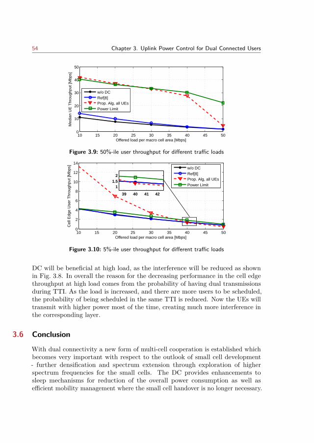
54 Chapter 3. Uplink Power Control for Dual Connected Users
10 15 20 25 30 35 40 45 500
10
20
30
40
50M
edia
n U
E T
hrou
ghpu
t [M
bps]
Offered load per macro cell area [Mbps]
w/o DCRef[8]Prop. Alg, all UEsPower Limit
Figure 3.9: 50%-ile user throughput for different traffic loads
10 15 20 25 30 35 40 45 500
2
4
6
8
10
12
14
Cel
l Edg
e U
ser
Thr
ough
put [
Mbp
s]
Offered load per macro cell area [Mbps]
w/o DCRef[8]Prop. Alg, all UEsPower Limit
39 40 41 42
11.5
2
Figure 3.10: 5%-ile user throughput for different traffic loads
DC will be beneficial at high load, as the interference will be reduced as shownin Fig. 3.8. In overall the reason for the decreasing performance in the cell edgethroughput at high load comes from the probability of having dual transmissionsduring TTI. As the load is increased, and there are more users to be scheduled,the probability of being scheduled in the same TTI is reduced. Now the UEs willtransmit with higher power most of the time, creating much more interference inthe corresponding layer.
3.6 Conclusion
With dual connectivity a new form of multi-cell cooperation is established whichbecomes very important with respect to the outlook of small cell development- further densification and spectrum extension through exploration of higherspectrum frequencies for the small cells. The DC provides enhancements tosleep mechanisms for reduction of the overall power consumption as well asefficient mobility management where the small cell handover is no longer necessary.
3.6. Conclusion 55
Most importantly, the dual connectivity allows for resource aggregation acrosscarries without the need of ideal backhaul connection. However, several technicalchallenges need to be addressed first. This chapter provides a comprehensiveoverview and discussion of the main issues that need to be considered for efficientresource aggregation for dual connected users. The work described treats theproblem of user power allocation scheme for dual connectivity with bearer split. Itproposes that two separate configurations per component carrier are maintained:one for single transmission and the other in case of dual transmissions withinTTI. The design on the power control has been simplified as to ensure minimalcoordination among base stations as well as minimal air interface signaling. Theperformance of the scheme has been assessed with system level simulations andcomparison with the previous case study has been evaluated. An importantoutcome of the study is that with bearer split high gains can be achieved forthe median and cell edge user throughput. For cell edge user throughput almostthreefold gain is accomplished for low load, while approximately 30% gain isachieved at high load (compared the case when DC is not configured). Theresults indicate that the distribution of the power is important in order to reducethe possible interference increase in the aggregation layer. At very low load,the decreased number of UE configured with DC can limit the gains from dualconnectivity, while at high load it is important to reduce the number of UEsconfigured with DC, due to the cell edge performances. The analysis also revealsthat the probability of a UE being scheduled in one TTI by two eNBs has highinfluence on the cell interference. This work also indicates that further study ofcoordination among eNBs scheduling is required in order to reduce the degradationof the coverage performance. This could be in a form of coordination for thescheduling grants towards cell edge users such that the probability for dualtransmission is kept low.
It should be underlined that dual connectivity is a very relevant architecturefor the future mobile networks, as it eliminates the need for stringent requirementsin the backhaul networks. Bearer split as part of dual connectivity, extends carrieraggregation for small cells, and is able to achieve high gains for the user. Therefore,bearer split becomes an important consideration for the future LTE release andupcoming 5G standards. The benefits from DC are multifold, however deeperstudy through investigations on the implications of dual connectivity is requiredbefore any real deployment takes place. In this line, further study on the impacton higher layers and other mechanism is also important. It is worth stating thatthe dual connectivity influences the UE sleep mechanisms such is DiscontinuousReception (DRX). The decisions on setting the related DRX parameters need tobe agreed among the eNBs in order for the UE to benefit from sleep cycles whilenot compromising the achievable throughput. Additionally, integration of the dualtransmission with multi-path TCP should be studied as well.

56
CHAPTER 4Optimal Traffic Allocation for
Multi-Stream Aggregation
Motivated by the multi-mode capability of the mobile devices and the fact thatthe heterogeneous wireless access networks overlap in coverage, mobile operatorsare looking for solutions that will benefit by simultaneous use of the availablemultiple access interfaces. The integration of different technologies through aggre-gation of two or more heterogeneous links has therefore received great attention.The benefit of such cooperation can be seen in improved data throughput andenhanced quality of experience. As such, this chapter investigates optimal trafficrate allocation method for multi-stream aggregation over heterogeneous networks.
The heterogeneity and the dynamic nature of radio access networks are consideredas important factors that determine the performance improvement by multi-streamaggregation. The optimization method proposed in this work, models the networksby different queuing systems in order to indicate networks with different qualityof service provisioning, capacity and delay variations. Furthermore, services withdifferent traffic characteristics in terms of QoS requirements are considered. Thesimulation results show the advantages of the proposed model with respect toefficient increase in data rate while ensuring accepted delay compared to traditionalschemes.
This chapter is organized as follows. Section 4.1 provides the motivation forthis work, while Section 4.2 provides an overview of the related work. Section 4.3introduces the network and traffic models, while Section 4.4 describes the opti-mization problem. Section 4.5 relaxes the optimization problem described in theprevious section, and presents a linear optimization analytical model. Section 4.6presents and analyses the results under different case studies for multi-streamaggregation. Conclusions and remarks for future work are given in the last section.
Note: This chapter is based on publication [3]. The text has been revised andappropriately modified for the purpose of this chapter. A copyright permission isenclosed.
57
58 Chapter 4. Optimal Traffic Allocation for Multi-Stream Aggregation
4.1 Introduction
Ever since the smart devices have entered the market, the demand for mobiledata traffic has resulted in stunning growth. Both, the development of smartdevice capabilities and improved processing power (screen resolution and pixeldensity), as well as vast range of diverse applications and services, impact thefuture forecast of the mobile data volumes [120]. On the other hand, the existingwireless technologies and providers differ in their capabilities to offer wider coverage,sufficient capacity and consistent QoS. Furthermore, most of the mobile stationstoday have an ability to simultaneously connect to different overlapping accessnetworks (for example an LTE and WiFi networks). In order to fully satisfythe needs of mobile users, these three facts inevitably lead toward a need of anintegration framework where advantages and disadvantages of each network, device,or application will compensate from each other and the user will get the most/bestof the available resources offered by the actual momentum of the heterogeneousenvironment. The level of cooperation and the integration play a significant rolein the network performance achieved by aggregation of the unique strengths ofthe each mobile technology.
By optimizing the traffic allocation at each node, the inter-RAT aggregationdeals with effective utilization of the available bandwidth across multiple radioaccess technologies. The previous chapter (Chapter 3) elaborated on the problem ofbearer split in case of dual connectivity which is a specific case of RAT aggregation.One of the challenges for such aggregation is the flow rate control between theaccess nodes, which defines how to effectively split the bearer. This chapter setsthe focus to an adaptive traffic rate allocation that can be used independentlyof the underlying technology and can be applied for both, intra-RAT and inter-RAT aggregation. In the proposed model the abstraction of the access nodes isdone through a queuing model and both, the heterogeneity (capacity, quality ofservice (QoS) provisioning) and the dynamic nature (load, heterogeneous trafficrequirements, delay variations) of the access networks are considered. The optimalaggregation is challenged by the heterogeneity and the dynamics of access networks.The flow rate control should improve the achievable data rate and the packetdelay, while minimizing the out-of-order packet delivery.
4.2 Related work
In a multi-RAT environment, multi-mode capable devices can simultaneouslyutilize the overlapping areas of various access networks for increased data rates,reduced handover rates and improved service. Achieving improved users’ qualityof experience by aggregation of multiple access networks has been studied ondifferent levels:
4.2. Related work 59
1. Physical layer: Carrier Aggregation. Multi-carrier aggregation between3GPP like technologies is covered by Release 12. Next step is the aggrega-tion of licenced and unlicenced spectrum (LTE Assisted Access, LAA) [121],while in the future, aggregation of any type of communication is expectedfor converged 5G system.
2. Link Layer: Dual Connectivity, LTE+WiFi Link Aggregation. It allows fortechnology aggregation at the RAN layer. The enhanced performance withthis approach has been validated by Qualcomm [122], Alcatel-Lucent [123]and KT [124] at the Mobile World Congress 2015. The focus in this work inon this approach as it relies on software updates at the mobile terminals andfeatures in the RAN. Furthermore, while achieving similar results to LAA,it does not require spectrum sensing or interference control mechanisms asin the previous approach.
3. TCP/IP Layer: Network Aggregation, Multi-path TCP. The concept issimilar to the previous one with the main difference that the traffic iscombined at a network proxy in the Internet, rather than at the cellular RAN[125], [126]. This type of approach require additional implementation/newhardware and the impact on the end-to-end characteristics of the individualpaths have high influence on the achieved performance.
The existing studies with respect to bandwidth aggregation provide extensiveanalysis of various static and dynamic policies for traffic allocations over het-erogeneous networks with different technologies and cell sizes ([39]-[40]). In [39]the cells are modeled with processor sharing queue, and only elastic traffic isconsidered. An optimization model with objective to minimize the mean sojourntime and balance the load among overlapping cells is considered. The study showsthat optimal performance can be achieved with knowledge of the average servicerates and number of incoming flows to the cells. The works in [41] and [42] showthe advantages of bandwidth aggregation in multi-hop networks. The numericalresults in [41] indicate the energy efficiency of the proposed flow distribution overmultiple interfaces and robustness to link outages. The work in [42] is based onframe aggregation in multi-hop networks, and the proposed optimization modelgives improvements of end-to-end delay and packet loss compared to a proactiverouting protocol.
In [127] the authors address the problem of joint subnet selection and optimaltraffic allocation to each subnet in order to maximize the data rates under QoSconstraints and subnet capacity. The available networks have been modeled as
60 Chapter 4. Optimal Traffic Allocation for Multi-Stream Aggregation
single server queuing system (M/M/1) with static subnet delays. In [128], networkcooperation of wireless personal and wide area networks has been considered,while the analytical model deals with minimization of transmission delay. Thesame network cooperation has been considered in [129], where the optimizationproblem is formulated as minimization of packet delay probability and cost forqueuing packets.
Rate allocation for multi-user video streaming has been addressed in [130],[131] and [40]. In [130] distortion-aware concurrent multipath transfer is proposed,while [131] minimizes the expected distortion of the video streams based on theavailable bit rate and round trip time. In [40] a layered video streaming allocationscheme is given, such that the video flow is divided into basic and enhance layers.The analytical model optimizes the transmission ratio of each layer and achievesimproved data rates under acceptable system delays. It also considers modificationsto the M/M/1 model for the transmission delay, such that the service rate isadapted based on the size of the queue.
The related work shows the importance and advantages of aggregation byanalyzing different proposed models under various study cases. In this work, anadditional degree of network heterogeneity is introduced by modeling differentdegrees of QoS provisioning. Thus, a novel traffic allocation scheme is proposedthat additionally considers how the services are provisioned and furthermoreconsiders buffering requirements due to packet reordering. A linear programmingmodel is defined and analysis is conducted by comparison with traditional modelsfor traffic allocation. The numerical results show that the proposed algorithmoutperforms the reference schemes in terms of achieved data rate, inter-packetdelay and buffering time.
4.3 System Model
The heterogeneous network considered in this work is consisted of two types ofaccess nodes: for example LTE and WiFi as illustrated in Figure 1. A mobileterminal in dual mode can connect to two (or more) access nodes at the sametime, such that the traffic from (UL) or to (DL) of the mobile terminal is dividedinto two separate streams. The delay and the data rate of each flow depend onthe system characteristics of each node, the volume of the incoming traffic foraccess points and the QoS requirements of the service. In this section, the trafficcharacteristics of the services are described first and then the queuing models usedto present the different access networks.
4.3.1 Service class and traffic characteristicsIn the analysis we focus on two classes of services. The services can be eitherreal-time that require guaranteed bit rate (GBR) or elastic for which the bit rate is
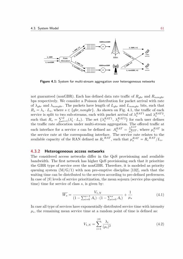
4.3. System Model 61
WiFi
λ
, GBR, i=
2
λ, GBR, i=1
λ, nonGBR, i=1
λ, nonGBR, i=2
λ, G
BR, i=1
λ, n
onGBR, i=1
µ
GBR/nonGBR
λ, GBR, i=2λ, nonGBR, i=2µ
GBR/nonGBR
Video
service
FTP
service
λ, GBR
λ, nonGBR
Rate
Allocation
RRH
Figure 4.1: System for multi-stream aggregation over heterogeneous networks
not guaranteed (nonGBR). Each has defined data rate traffic of Rgbr and Rnongbrbps respectively. We consider a Poisson distribution for packet arrival with rateof λgbr and λnongbr. The packets have length of Lgbr and Lnongbr bits, such thatRs = λs · Ls, where s ∈ gbr, nongbr. As shown on Fig. 4.1, the traffic of eachservice is split to two sub-streams, each with packet arrival of λRAT1
s and λRAT2s ,
such that Rs =∑2i=1(λis · Ls). The set λRAT1
s , λRAT2s for each user defines
the traffic rate allocation under multi-stream aggregation. The offered traffic ateach interface for a service s can be defined as: ARATs = λRATs
µRATs, where µRATs is
the service rate at the corresponding interface. The service rate relates to theavailable capacity of the RAN defined as RcRAT , such that µRATs = Rc
RAT /Ls.
4.3.2 Heterogeneous access networksThe considered access networks differ in the QoS provisioning and availablebandwidth. The first network has higher QoS provisioning such that it prioritizethe GBR type of service over the nonGBR. Therefore, it is modeled as priorityqueuing system (M/G/1) with non pre-emptive discipline [132], such that thewaiting time can be distributed to the services according to pre-defined preferences.In case of |S| levels of service prioritization, the mean sojourn (service plus queuingtime) time for service of class s, is given by:
Ws = V1,N
(1−∑s−1i=0 Ai) · (1−
∑si=0Ai)
+ 1µs
(4.1)
In case all type of services have exponentially distributed service time with intensityµi, the remaining mean service time at a random point of time is defined as:
V1,N =|S|∑i=1
λi(µi)2 (4.2)
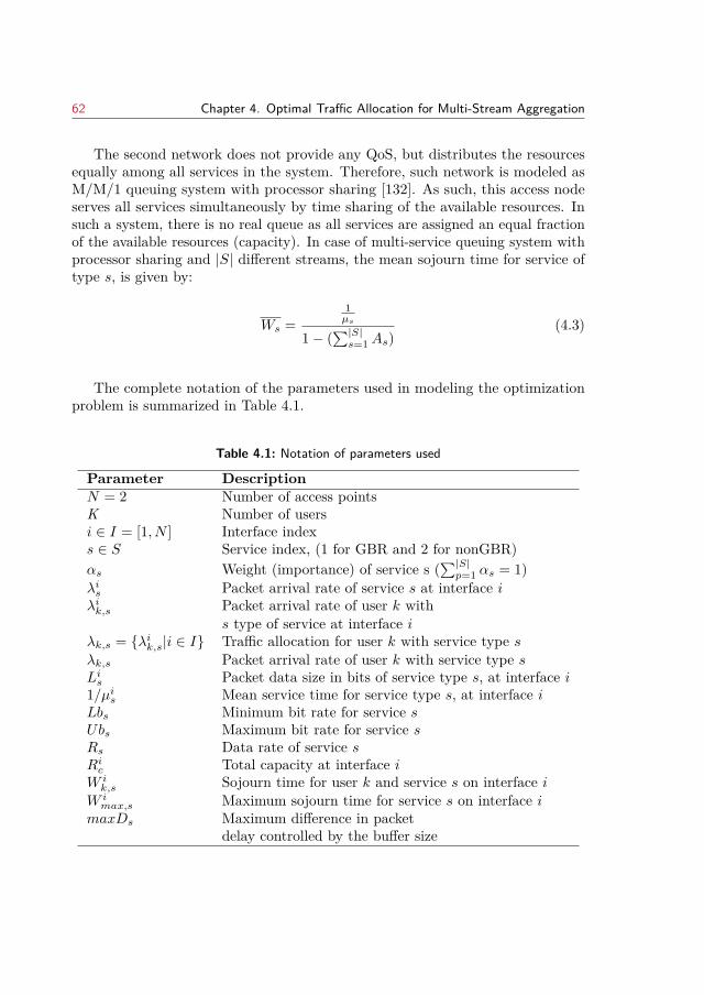
62 Chapter 4. Optimal Traffic Allocation for Multi-Stream Aggregation
The second network does not provide any QoS, but distributes the resourcesequally among all services in the system. Therefore, such network is modeled asM/M/1 queuing system with processor sharing [132]. As such, this access nodeserves all services simultaneously by time sharing of the available resources. Insuch a system, there is no real queue as all services are assigned an equal fractionof the available resources (capacity). In case of multi-service queuing system withprocessor sharing and |S| different streams, the mean sojourn time for service oftype s, is given by:
Ws =1µs
1− (∑|S|s=1As)
(4.3)
The complete notation of the parameters used in modeling the optimizationproblem is summarized in Table 4.1.
Table 4.1: Notation of parameters used
Parameter DescriptionN = 2 Number of access pointsK Number of usersi ∈ I = [1, N ] Interface indexs ∈ S Service index, (1 for GBR and 2 for nonGBR)αs Weight (importance) of service s (
∑|S|p=1 αs = 1)
λis Packet arrival rate of service s at interface iλik,s Packet arrival rate of user k with
s type of service at interface iλk,s = λik,s|i ∈ I Traffic allocation for user k with service type sλk,s Packet arrival rate of user k with service type sLis Packet data size in bits of service type s, at interface i1/µis Mean service time for service type s, at interface iLbs Minimum bit rate for service sUbs Maximum bit rate for service sRs Data rate of service sRic Total capacity at interface iW ik,s Sojourn time for user k and service s on interface i
W imax,s Maximum sojourn time for service s on interface i
maxDs Maximum difference in packetdelay controlled by the buffer size
4.4. Optimal Traffic Rate Allocation 63
4.4 Optimal Traffic Rate Allocation
In this work the objective is to minimize the maximum delay per application asto reduce the variance in the delay on each interface. The maximum delay is ofimportance as indicated in [125], while the difference between the delay over thelinks has influence on packet reordering [133]. For bandwidth aggregation overtwo heterogeneous networks, the main challenge is estimating the characteristicsof the available networks, such as delay and throughput. Since the links havedifferent propagation delays and queuing delays the packet can be delivered outof order. There are two ways to overcome out-of-order packets: 1 by sendingthe packets in predefined order so that they are delivered in order at the receiver(thus minimizing the out-of-order delivery) or 2 by using larger buffers at thereceiver side. Out-of-order packets are less problematic for elastic services, butmuch critical for delay sensitive applications, such as gaming, video streaming,etc.
Using the notation in Table 4.1 and the eq.( 4.1) and eq.( 4.3), the total sojourndelay per each interface for every type of service can be summarized as:
W ik,s =
∑|S|p=1
(λik,p
+λip)
(µip)2
1−λik,s
+λisµis
+ 1µis, (i = 1, s = 1)
∑|S|p=1
(λik,p
+λip)
(µip)2
(1−∑s−1
p=1
λik,p
+λipµip
)·(1−∑s
p=1
λik,p
+λipµip
)+ 1
µis, (i = 1, s ≥ 2)
1µis
1−∑|S|
p=1
λip+λik,p
µip
, (i = 2, s ∈ S)
(4.4)
In order to increase overall QoS, under the given constraint of data rate foreach service, the objective of the traffic allocation in case of multi-RAT aggregationcan be defined as minimization of the maximum transmission delay. Hence, theoptimization problem can be summarized as:
64 Chapter 4. Optimal Traffic Allocation for Multi-Stream Aggregation
mins
maxiW ik,s (4.5)
subject to:|S|∑s=1
(λik,s + λis) · Lis ≤ Ric, i ∈ I (4.6)
0 ≤ λik,s + λis < µis, s ∈ S, i ∈ I (4.7)
Rs =N∑i=1
(λik,s · Ls), s ∈ S (4.8)
|W 1k,s −W 2
k,s| ≤ maxDs, s ∈ S (4.9)
The set λk,s = λik,s|i ∈ I defines the optimal traffic allocation for each user ofservice type s ∈ S. The objective function (4.5) of the optimization problem isdefined as minimization of the maximum delay. For two type of services, twounknowns (Wk,s) are added to the optimization problem in order to balanceminimization of the maximum delay for GBR compared to the maximum delayat the nonGBR service. Constraint (4.6) ensures that the sum of the trafficthat is accepted by the radio access node does not exceed the available capacity.Constraint (4.7) must be satisfied in order to ensure statistical equilibrium andsteady state of the queues. Constraint (4.8) reflects the data rate requirements ofeach service, while constraint (4.9) reflects the buffer size at the receiver that isresponsible for packet reordering. The number of packets being buffered dependson the traffic allocation, while the time that they are buffered depends on the delaydifference. Delaying the packets at the sender side by buffering at each interfacewith time dmaximum − dinterface, reduces out-of-order packet delivery. Therefore,by controlling the delay difference, the buffering requirements are controlled aswell. Furthermore, this is also important because the transmission buffers mayintroduce delays that are not tolerant for some delay sensitive applications [126].The value of the maxDs should be chosen reasonable, that is to consider thepacket inter-arrival rate.
The optimization problem defined through (4.5)-(4.9) is non-linear and there isno evidence that the objective function is convex. The common methods for solvingconvex optimizations are not applicable in this case. Alternative, numerical searchmethods can be used, but the search space due to four unknown is quite large.Therefore, in the following section transformation of the oprimization problem isdone in order to lead to a linear and simpler optimization problem.
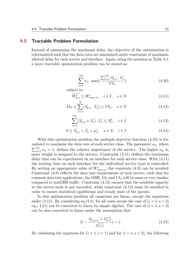
4.5. Tractable Problem Formulation 65
4.5 Tractable Problem Formulation
Instead of minimizing the maximum delay, the objective of the optimization isreformulated such that the data rates are maximized under constraints of maximumallowed delay for each service and interface. Again, using the notation in Table 4.1,a more tractable optimization problem can be stated as:
|S|∑s=1
αs ·max(∑|N |i=1 λ
ik,s · Lis
Ubs) (4.10)
subject to:W ik,s ≤W
imax,s, i ∈ I, s ∈ S (4.11)
Lbs ≤N∑i=1
(λik,s · Lis) ≤ Ubs, s ∈ S (4.12)
|S|∑s=1
(λik,s + λis) · Lis ≤ Ric, i ∈ I (4.13)
0 ≤ λik,s + λis < µis, s ∈ S, i ∈ I (4.14)
With this optimization problem the multiple-objective function (4.10) is for-mulated to maximize the data rate of each service class. The parameter αp, where∑|S|s=1 αs = 1, defines the relative importance of the service. The higher αp is,
more weight is assigned to the service. Constraint (4.11) defines the maximumdelay that can be experienced on an interface for each service class. With (4.11)the waiting time on each interface for the individual service type is controlled.By setting an appropriate value of W i
max,s, the constrain (4.9) can be avoided.Constraint (4.8) reflects the data rate requirements of each service, such that forconstant data rate applications, the GBR, Lbs and Ubs will be same or very similar,compared to nonGBR traffic. Constraint (4.13) ensures that the available capacityat the access node is not exceeded, while constraint (4.14) must be satisfied inorder to ensure statistical equilibrium and steady state of the queues.
In this optimization problem all equations are linear, except the equationsunder (4.11). By considering eq.(4.4), for all cases except the case of (i = 1, s = 2)eq.( 4.11) can be converted to linear by simple algebra. The case of (i = 1, s = 2)can be also converted to linear under the assumption that
(1−λik,s=1 + λi=1
s=1
µi=1s=1
) ∼ 1 (4.15)
By combining the equations for (i = 1, s = 1) and for (i = 1, s = 2), the following
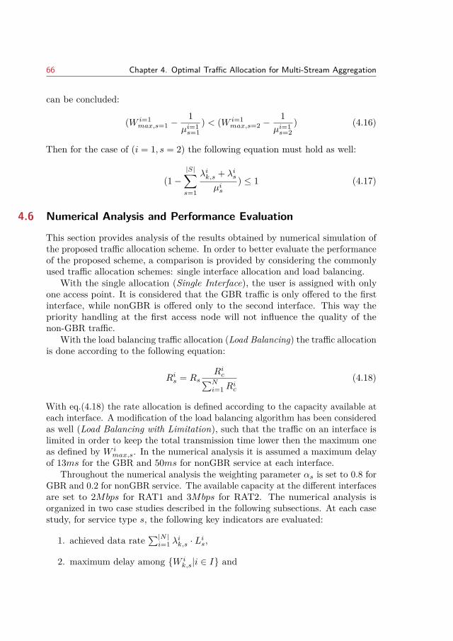
66 Chapter 4. Optimal Traffic Allocation for Multi-Stream Aggregation
can be concluded:
(W i=1max,s=1 −
1µi=1s=1
) < (W i=1max,s=2 −
1µi=1s=2
) (4.16)
Then for the case of (i = 1, s = 2) the following equation must hold as well:
(1−|S|∑s=1
λik,s + λisµis
) ≤ 1 (4.17)
4.6 Numerical Analysis and Performance Evaluation
This section provides analysis of the results obtained by numerical simulation ofthe proposed traffic allocation scheme. In order to better evaluate the performanceof the proposed scheme, a comparison is provided by considering the commonlyused traffic allocation schemes: single interface allocation and load balancing.
With the single allocation (Single Interface), the user is assigned with onlyone access point. It is considered that the GBR traffic is only offered to the firstinterface, while nonGBR is offered only to the second interface. This way thepriority handling at the first access node will not influence the quality of thenon-GBR traffic.
With the load balancing traffic allocation (Load Balancing) the traffic allocationis done according to the following equation:
Ris = RsRic∑Ni=1R
ic
(4.18)
With eq.(4.18) the rate allocation is defined according to the capacity available ateach interface. A modification of the load balancing algorithm has been consideredas well (Load Balancing with Limitation), such that the traffic on an interface islimited in order to keep the total transmission time lower then the maximum oneas defined by W i
max,s. In the numerical analysis it is assumed a maximum delayof 13ms for the GBR and 50ms for nonGBR service at each interface.
Throughout the numerical analysis the weighting parameter αs is set to 0.8 forGBR and 0.2 for nonGBR service. The available capacity at the different interfacesare set to 2Mbps for RAT1 and 3Mbps for RAT2. The numerical analysis isorganized in two case studies described in the following subsections. At each casestudy, for service type s, the following key indicators are evaluated:
1. achieved data rate∑|N |i=1 λ
ik,s · Lis,
2. maximum delay among W ik,s|i ∈ I and
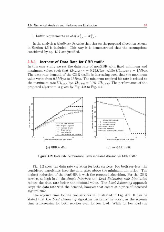
4.6. Numerical Analysis and Performance Evaluation 67
3. buffer requirements as abs(W 1k,s −W 2
k,s).
In the analysis a Nonlinear Solution that threats the proposed allocation schemein Section 4.5 is included. This way it is demonstrated that the assumptionsconsidered by eq. 4.17 are justified.
4.6.1 Increase of Data Rate for GBR trafficIn this case study we set the data rate of nonGBR with fixed minimum andmaximum value, such that LbnonGBR = 0.25Mbps, while UbnonGBR = 1Mbps.The data rate demand of the GBR traffic is increasing such that the maximumvalue varies from 0.5Mbps to 3Mbps. The minimum required bit rate is related tothe maximum rate UbGBR by: LbGBR = 0.75 · UbGBR. The performance of theproposed algorithm is given by Fig. 4.2 to Fig. 4.4.
0.5 1 1.5 2 2.5 30
0.5
1
1.5
2
2.5
3
Data rate demand for GBR traffic [Mbps]
Dat
a ra
te o
f GB
R s
ervi
ce [M
bps]
Min. GBR data rateProposed AlgorithmNonlinear SolutionSingle InterfaceLoad BalancingLoad Balancing with Limitation
(a) GBR traffic
0.5 1 1.5 2 2.5 30.2
0.3
0.4
0.5
0.6
0.7
0.8
0.9
1
Data rate demand for GBR traffic [Mbps]
Dat
a ra
te o
f non
GB
R s
ervi
ce [M
bps]
Min. nonGBR data rateProposed AlgorithmNonlinear SolutionSingle InterfaceLoad BalancingLoad Balancing with Limitation
(b) nonGBR traffic
Figure 4.2: Data rate performance under increased demand for GBR traffic
Fig. 4.2 show the data rate variation for both services. For both services, theconsidered algorithms keep the data rates above the minimum limitation. Thehighest reduction of the nonGBR is with the proposed algorithm. For the GBRservice, at high load, the Single Interface and Load Balancing with Limitationreduce the data rate below the minimal value. The Load Balancing approachkeeps the data rate with the demand, however that comes at a price of increasedsojourn time.
The sojourn time for the two services in illustrated in Fig. 4.3. It can bestated that the Load Balancing algorithm performs the worst, as the sojourntime is increasing for both services even for low load. While for low load the
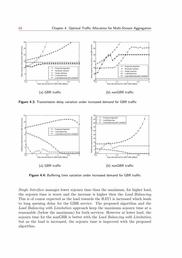
68 Chapter 4. Optimal Traffic Allocation for Multi-Stream Aggregation
0.5 1 1.5 2 2.5 30
5
10
15
20
25
30
Data rate demand for GBR traffic [Mbps]
Mea
n so
ujou
rn ti
me
[ms]
for
GB
R s
ervi
ce
Proposed AlgorithmNonlinear SolutionSingle InterfaceLoad BalancingLoad Balancing with Limitation
(a) GBR traffic
0.5 1 1.5 2 2.5 330
35
40
45
50
55
60
Data rate demand for GBR traffic [Mbps]
Mea
n so
ujou
nr ti
me
[ms]
for
nonG
BR
ser
vice
Proposed AlgorithmNonlinear SolutionSingle InterfaceLoad BalancingLoad Balancing with Limitation
(b) nonGBR traffic
Figure 4.3: Transmission delay variation under increased demand for GBR traffic
0.5 1 1.5 2 2.5 30
2
4
6
8
10
12Priority service
Data rate demand for GBR traffic [Mbps]
Buf
ferin
g re
quire
men
ts fo
r G
BR
ser
vice
[ms]
Proposed AlgorithmLoad BalancingLoad Balancing with Limitation
(a) GBR traffic
0.5 1 1.5 2 2.5 30
5
10
15
20
25
30
35
40
45
50Second service
Data rate demand for GBR traffic [Mbps]
Buf
ferin
g re
quire
men
ts fo
r no
nGB
R s
ervi
ce [m
s]
Proposed AlgorithmLoad BalancingLoad Balancing with Limitation
(b) nonGBR traffic
Figure 4.4: Buffering time variation under increased demand for GBR traffic
Single Interface manages lower sojourn time than the maximum, for higher load,the sojourn time is worst and the increase is higher then the Load Balancing.This is of course expected as the load towards the RAT1 is increased which leadsto long queuing delay for the GBR service. The proposed algorithm and theLoad Balancing with Limitation approach keep the maximum sojourn time at areasonable (below the maximum) for both services. However at lower load, thesojourn time for the nonGBR is better with the Load Balancing with Limitation,but as the load is increased, the sojourn time is improved with the proposedalgorithm.
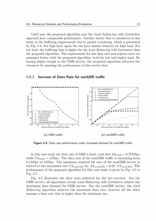
4.6. Numerical Analysis and Performance Evaluation 69
Until now the proposed algorithm and the Load Balancing with Limitationapproach have comparable performance. Another metric that is considered in thisstudy is the buffering requirements due to packet reordering, which is presentedby Fig. 4.4. For high load, again the two have similar behavior for high load. Forlow load, the buffering time is higher for the Load Balancing with Limitation thanthe proposed algorithm. The requirements for the data rate and sojourn time aremanaged better with the proposed algorithm, both for low and higher load. Byhaving higher weight to the GBR service, the proposed algorithm allocates theresources by ensuring the performance of this service first.
4.6.2 Increase of Data Rate for nonGBR traffic
0 0.5 1 1.5 2 2.5 3 3.5 40.4
0.5
0.6
0.7
0.8
0.9
1
Data rate demand for nonGBR traffic [Mbps]
Dat
a ra
te o
f GB
R s
ervi
ce [M
bps]
Min. nonGBR data rateProposed AlgorithmNonlinear SolutionSingle InterfaceLoad BalancingLoad Balancing with Limitation
(a) GBR traffic
0 0.5 1 1.5 2 2.5 3 3.5 40
0.5
1
1.5
2
2.5
3
3.5
4
Data rate demand for nonGBR traffic [Mbps]
Dat
a ra
te o
f non
GB
R tr
affic
[Mbp
s]
Min. nonGBR data rateProposed AlgorithmNonlinear SolutionSingle InterfaceLoad BalancingLoad Balancing with Limitation
(b) nonGBR traffic
Figure 4.5: Data rate performance under increased demand for nonGBR traffic
In this case study the data rate of GBR is fixed, such that LbGBR = 0.75Mbps,while UbGBR = 1Mbps. The data rate of the nonGBR traffic is increasing from0.1Mbps to 4Mbps. The minimum required bit rate of the nonGBR service isrelated to the maximum rate UbnonGBR by: LbnonGBR = 0.25 · UbnonGBR. Theperformance of the proposed algorithm for this case study is given by Fig. 4.5 toFig. 4.7.
Fig. 4.5 illustrates the data rates achieved for the two services. For theGBR service, all algorithms except Load Balancing with Limitation achieve themaximum data demand for GBR service. For the nonGBR service, the LoadBalancing algorithm achieves the maximum data rate, however all the othermanage a data rate that is higher then the minimum one.
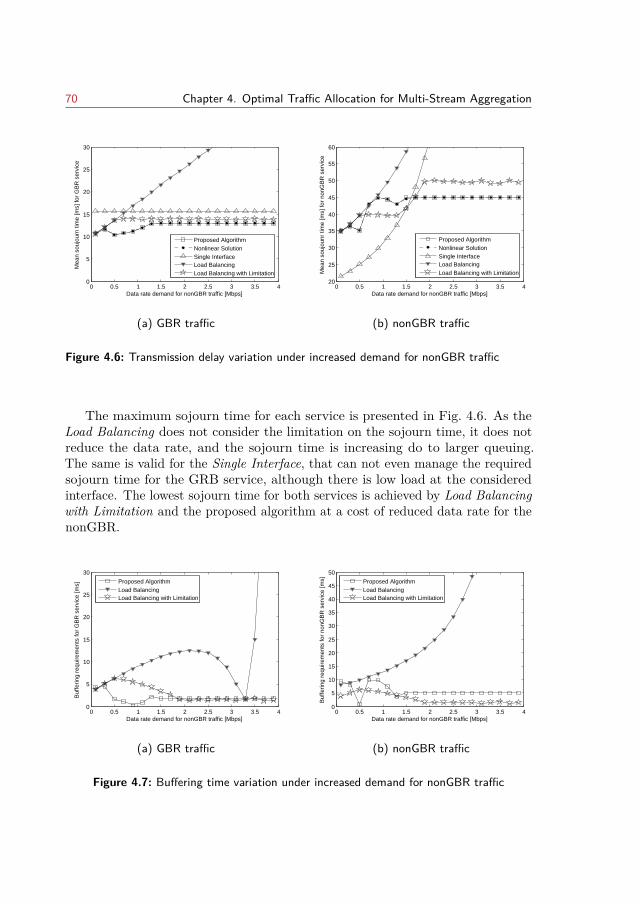
70 Chapter 4. Optimal Traffic Allocation for Multi-Stream Aggregation
0 0.5 1 1.5 2 2.5 3 3.5 40
5
10
15
20
25
30
Data rate demand for nonGBR traffic [Mbps]
Mea
n so
ujou
rn ti
me
[ms]
for
GB
R s
ervi
ce
Proposed AlgorithmNonlinear SolutionSingle InterfaceLoad BalancingLoad Balancing with Limitation
(a) GBR traffic
0 0.5 1 1.5 2 2.5 3 3.5 420
25
30
35
40
45
50
55
60
Data rate demand for nonGBR traffic [Mbps]
Mea
n so
ujou
nr ti
me
[ms]
for
nonG
BR
ser
vice
Proposed AlgorithmNonlinear SolutionSingle InterfaceLoad BalancingLoad Balancing with Limitation
(b) nonGBR traffic
Figure 4.6: Transmission delay variation under increased demand for nonGBR traffic
The maximum sojourn time for each service is presented in Fig. 4.6. As theLoad Balancing does not consider the limitation on the sojourn time, it does notreduce the data rate, and the sojourn time is increasing do to larger queuing.The same is valid for the Single Interface, that can not even manage the requiredsojourn time for the GRB service, although there is low load at the consideredinterface. The lowest sojourn time for both services is achieved by Load Balancingwith Limitation and the proposed algorithm at a cost of reduced data rate for thenonGBR.
0 0.5 1 1.5 2 2.5 3 3.5 40
5
10
15
20
25
30Priority service
Data rate demand for nonGBR traffic [Mbps]
Buf
ferin
g re
quire
men
ts fo
r G
BR
ser
vice
[ms]
Proposed AlgorithmLoad BalancingLoad Balancing with Limitation
(a) GBR traffic
0 0.5 1 1.5 2 2.5 3 3.5 40
5
10
15
20
25
30
35
40
45
50Second service
Data rate demand for nonGBR traffic [Mbps]
Buf
ferin
g re
quire
men
ts fo
r no
nGB
R s
ervi
ce [m
s]
Proposed AlgorithmLoad BalancingLoad Balancing with Limitation
(b) nonGBR traffic
Figure 4.7: Buffering time variation under increased demand for nonGBR traffic
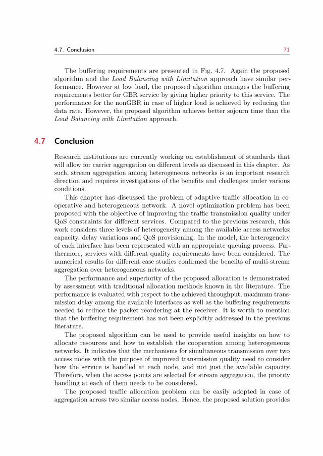
4.7. Conclusion 71
The buffering requirements are presented in Fig. 4.7. Again the proposedalgorithm and the Load Balancing with Limitation approach have similar per-formance. However at low load, the proposed algorithm manages the bufferingrequirements better for GBR service by giving higher priority to this service. Theperformance for the nonGBR in case of higher load is achieved by reducing thedata rate. However, the proposed algorithm achieves better sojourn time than theLoad Balancing with Limitation approach.
4.7 Conclusion
Research institutions are currently working on establishment of standards thatwill allow for carrier aggregation on different levels as discussed in this chapter. Assuch, stream aggregation among heterogeneous networks is an important researchdirection and requires investigations of the benefits and challenges under variousconditions.
This chapter has discussed the problem of adaptive traffic allocation in co-operative and heterogeneous network. A novel optimization problem has beenproposed with the objective of improving the traffic transmission quality underQoS constraints for different services. Compared to the previous research, thiswork considers three levels of heterogeneity among the available access networks:capacity, delay variations and QoS provisioning. In the model, the heterogeneityof each interface has been represented with an appropriate queuing process. Fur-thermore, services with different quality requirements have been considered. Thenumerical results for different case studies confirmed the benefits of multi-streamaggregation over heterogeneous networks.
The performance and superiority of the proposed allocation is demonstratedby assessment with traditional allocation methods known in the literature. Theperformance is evaluated with respect to the achieved throughput, maximum trans-mission delay among the available interfaces as well as the buffering requirementsneeded to reduce the packet reordering at the receiver. It is worth to mentionthat the buffering requirement has not been explicitly addressed in the previousliterature.
The proposed algorithm can be used to provide useful insights on how toallocate resources and how to establish the cooperation among heterogeneousnetworks. It indicates that the mechanisms for simultaneous transmission over twoaccess nodes with the purpose of improved transmission quality need to considerhow the service is handled at each node, and not just the available capacity.Therefore, when the access points are selected for stream aggregation, the priorityhandling at each of them needs to be considered.
The proposed traffic allocation problem can be easily adopted in case ofaggregation across two similar access nodes. Hence, the proposed solution provides
72 Chapter 4. Optimal Traffic Allocation for Multi-Stream Aggregation
flexibility and can be applied for different deployments. The stream aggregationcan also be performed over network belonging to different operators in order toimprove the offered service quality. As such the numerical results can be usedby the mobile operators as to enter into cooperative agreements, and by that theresults will effectively influence the operator’s business model.
CHAPTER 5Cloud Radio Access Network
This chapter pays due attention to the optimizations and enhancements requiredfor a RAN that will be able to complement the technological advances on the airinterface. The core topic of this chapter is the C-RAN, a leading technology thatensures low operational and capital expenditures associated with the provision ofthe telecommunication services. C-RAN is based on pooling and centralization ofbaseband processing, exploiting the advantages of cloud computing concept andtechnology.
Proper resource placement and dimensioning of the pools is required in orderto provide the desired QoS in C-RAN under acceptable cost and energy conditions.The dimensioning of the pool should exploit the so-called tidal effect due to usermobility in cellular networks, in order to maximize the cost savings on basebandprocessing. The fist part of this chapter analyzes the pooling gains in heterogeneousnetworks with various cell traffic profiles. Based on the analysis the key parametersand conditions for cell deployment optimization are identified.
However, the multiplexing gains achieved by full centralization of the basebandprocessing can not always justify the expenditure in the fronthaul network. Incase of full centralization, the low transport efficiency in the fronthaul challengesthe cost-effectiveness of C-RAN. Redesign of the C-RAN through functional splitin the baseband processing chain has been proposed to overcome these challenges.Therefore, the second part of this chapter considers heterogeneous networks withcells that are served with different splits. The study quantifies the trade-offsbetween centralization and decentralization concerning the cost of the pool (gains),fronthaul network capacity and resource utilization.
This chapter is organized as follows. After the introductory motivation inSection 5.1, the related work is presented in Section 5.2. The analytical modelused in this chapter is presented in Section 5.3. Section 5.4 discusses the approachtaken in this work to evaluate the multiplexing gains by pooling resources, as wellas principles for pool dimensioning. The multiplexing gains due to the tidal effectare evaluated in Section 5.5, while Section 5.6 analyses heterogeneous deploymentswith respect to fronthaul splits. Concluding remarks are offered in Section 5.7.
Note: This chapter is based on publications [1] and [4]. The text has beenrevised and appropriately modified for the purpose of this chapter. A copyrightpermission is enclosed.
73
74 Chapter 5. Cloud Radio Access Network
5.1 Introduction
The strong advances on the processing abilities at the mobile devices as well asinnovative and popular applications, have pushed the focus of mobile networks fromvoice to data dominated. In the past few years, there has been exponential growthof the mobile data traffic, that is expected to continue even more rapidly in the nextyears, especially in the busy hours [19]. The forecast for high capacity and coveragedemand, together with the mobile subscriber proliferation and increased userexpectations, has lead to fast development of cellular networks, where densificationand advanced air interface technologies have prevailing importance.
The current cellular networks with the traditional design of base station arehighly inefficient. The operator need to dimension the BS according to the peakhours, thus leading to over-provisioning of resources. In fact measurement reportsshow that the offered traffic varies both geographically and temporarily, leadingto only 15-20% of the sites to carry 50% of the total traffic[134]. Secondly, thetraditional design of the BS limits the tight coordination among the resourcemanagement at each cell, thus prohibits advanced cooperation technologies such asCoMP, CA and (massive) MIMO. Thirdly, most of operators costs are associatedwith the RAN, that is 60% of CAPEX and 80% of OPEX [135], and they willcontinue to increase drastically with network densification. These costs togetherwith the flat subscription rates, decreases the operators revenue and challengesthe economical profitability of the cellular networks.
Striving towards cost and energy efficient mobile networks, C-RAN designatesa leading technology for the RAN architecture [136] that addresses the exponentialgrowth of the mobile traffic. C-RAN inherits the design of a distributed BS,where the RRH is separated and connected via fiber to the baseband processingserver, called BBU. The baseband processing is gathered in a centralized pool,which facilitates advanced multi-cell cooperation techniques. Thus the radioresource management is more efficient as the network is flexible and scalable tothe temporally and spatial fluctuations of the mobile traffic. The centralization isfurther enhanced with cloud computing [62], providing elasticity and virtualizationwith possibility for multitenancy among operators. The computational resourcescan be pooled and dynamically allocated to a virtual BS, which brings cost-effectivehardware and software design [137]. Thus the statistical multiplexing gains thatcan be achieved by C-RAN, scale with the mobile operator costs: with C-RANless equipment is required and as such the CAPEX of the network is to be reduced.Less energy will be required to operate the pool of BBUs, thus energy savings canbe achieved which directly lowers the OPEX of the network [64].
The multiplexing gains achieved by pooling the baseband resources, have beenquantified by several contributions [138, 139, 140, 141, 142, 143, 144]. Theirobservations of the cost and energy savings by multiplexing are obtained basedon simulations. While the simulation based analysis gives better insight on the
5.2. Related Work 75
protocol interaction, the mathematical approach allows to create simpler modelsthat provides the basis for analysis, design and optimization of fronthaul andbackhaul deployments. In the work presented by this chapter, traffic engineeringapproach is used in order to perform a quantitative study of C-RAN, and evaluatethe cost and energy savings. The focus is placed on the multiplexing gainscoming from traffic depended sources, that is user data and heterogeneous trafficcharacteristics. The models used are based on multi-dimensional Markov modeland direct routing network model, and are able to capture the session leveldynamics in the network as well as the relation between baseband processing andradio resource requirements. Furthermore, the derived mathematical model can beused to initially investigate and indicate the conditions for optimal dimensioningof the BBU pools (Section 5.5).
With the initial proposal for C-RAN, where the complete baseband processingis centralized, radio samples are exchanged between the RRH and BBU pool.This architecture yields a fronthaul that requires high bandwidth and low latencyinterconnect network. Therefore the fronthaul network presents cost burden tothe C-RAN architecture, especially when high number of cells are associatedwith the BBU pool. In order to alleviate this challenge, alternative interfacingbetween the RRH and BBU pool have been proposed [70]. Furthermore, theconcept of Heterogeneous C-RAN has emerged, where the resources from the lowpower nodes are pooled, while the high power nodes are interconnected with thetraditional S1/X2 link towards the BBU pool [145]. The main purpose of suchheterogeneous C-RAN is to provide improved signaling and resource managementthrough coordinated cross cell scheduling and hybrid backhauling [146, 147].
The optimal solution on how to split the baseband functionality representsan open challenge that has been addressed in this chapter as well. Based onthe direct routing network model, a mathematical model to analyze differentsplit points in terms of multiplexing gains is derived. The results show that inheterogeneous deployments, when cells are served by different splits, differentmultiplexing gains can be achieved at the fronthaul links and at the BBU pool. Inthis line, Section 5.6 considers flexible and heterogeneous design on the fronthaulnetwork and evaluates the costs due to processing requirements, fronthaul capacityand overall resource efficiency.
5.2 Related Work
The possible multiplexing gains achieved with C-RAN have been evaluated by theresearch and industry community. In [138] Werthmann et al. show multiplexinggains can be achieved if multiple sectors are aggregated into one single cloud basestation and the spatial user distribution has high influence on the compute resourceload. A framework for partitioning base stations into groups and their scheduling
76 Chapter 5. Cloud Radio Access Network
on a multi-core compute platform is proposed by Bhaumik et al. in [139]. Theyconclude that the variation in the processing load across base stations leads tosavings of compute resources. The statistical multiplexing gain as a function ofcell layout has been analyzed by Namba et al. in [140]. In [141] Madhavan etal. quantify the multiplexing gain of consolidating WiMAX base stations underdifferent traffic conditions. They show that the gain increases linearly with networksize and it is higher when base stations are experiencing higher traffic intensity.However, in [61] Liu et al. show the opposite, that the multiplexing gain reachessignificant level for the medium-size pools and the increase in gain for larger poolsin negligible.
The multiplexing gains under different cell traffic profiles has been analyzed in[142] based on system level simulator. Based on the simulation results, the paperconcludes the set of parameters that maximizes the potential cost savings withC-RAN. Furthermore, a packet based fronthaul architecture is proposed in order toenable flexible assignments between RRH and BBU pools. The benefit of dynamicassignment of baseband processing to RRHs has been further analyzed in [143]and [144], where it has been emphasized that one to one mapping of BBU andRRH is sub-optimal. Their work shows that the configuration in the network mustbe flexible in order to provide high performance and energy efficiency. Semi-staticand dynamic RRH-BBU switching schemes have been proposed and analyzedwith respect to efficiency in the BBU pool. The results show that a percentage ofBBUs can be reduced, depending on the traffic load and the applied scheme forassignment.
5.3 Direct Routing Network Model
Teletraffic theory has been used for planning and administration of real telecom-munications systems even when the first telephone system became commerciallyavailable. The models are technology independent, and are based on the relation-ship between the system capacity and its characteristic, the strategy of operationand the statistical properties of the traffic. The main purpose is to derive thedependency towards the grade of service and assist the decision making related tothe optimization of telecommunication systems. An overview of different mathe-matical models, their characteristics and relevance is provided in [148], while abroad application of different models for modeling and dimensioning of mobilenetworks is given in [149].
The direct routing network model used in this work provides an engineeringtool to study the multiplexing gains in hierarchical cellular networks [150]. Thenumerical results from the analysis influence the decisions for cellular systemsdimensioning. As the network model itself is complex, it is worth to first introducethe model for a single link which the network is composed of.
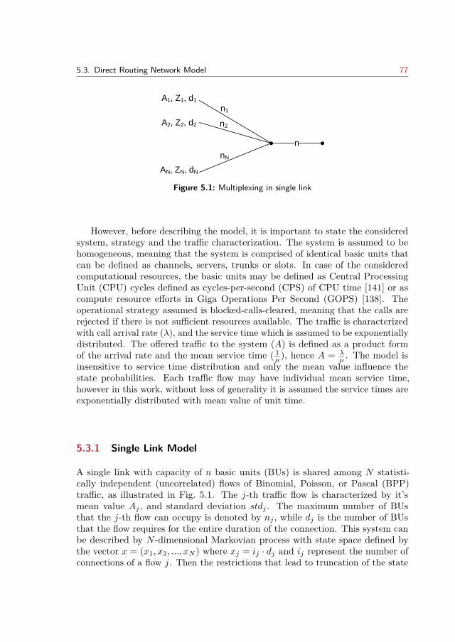
5.3. Direct Routing Network Model 77
n
A1, Z1, d1
A2, Z2, d2
AN, ZN, dN
nN
nN
nN
n1
n2
Figure 5.1: Multiplexing in single link
However, before describing the model, it is important to state the consideredsystem, strategy and the traffic characterization. The system is assumed to behomogeneous, meaning that the system is comprised of identical basic units thatcan be defined as channels, servers, trunks or slots. In case of the consideredcomputational resources, the basic units may be defined as Central ProcessingUnit (CPU) cycles defined as cycles-per-second (CPS) of CPU time [141] or ascompute resource efforts in Giga Operations Per Second (GOPS) [138]. Theoperational strategy assumed is blocked-calls-cleared, meaning that the calls arerejected if there is not sufficient resources available. The traffic is characterizedwith call arrival rate (λ), and the service time which is assumed to be exponentiallydistributed. The offered traffic to the system (A) is defined as a product formof the arrival rate and the mean service time ( 1
µ ), hence A = λµ . The model is
insensitive to service time distribution and only the mean value influence thestate probabilities. Each traffic flow may have individual mean service time,however in this work, without loss of generality it is assumed the service times areexponentially distributed with mean value of unit time.
5.3.1 Single Link Model
A single link with capacity of n basic units (BUs) is shared among N statisti-cally independent (uncorrelated) flows of Binomial, Poisson, or Pascal (BPP)traffic, as illustrated in Fig. 5.1. The j-th traffic flow is characterized by it’smean value Aj , and standard deviation stdj . The maximum number of BUsthat the j-th flow can occupy is denoted by nj , while dj is the number of BUsthat the flow requires for the entire duration of the connection. This system canbe described by N -dimensional Markovian process with state space defined bythe vector x = (x1, x2, ..., xN ) where xj = ij · dj and ij represent the number ofconnections of a flow j. Then the restrictions that lead to truncation of the state
78 Chapter 5. Cloud Radio Access Network
space can be formulated as:
0 ≤ xj ≤ nj ,N∑j=1
xj ≤ n, where
N∑j=1
nj ≥ n (5.1)
In the case n is sufficiently large such that there is no global restriction, the systemcorresponds to N independent one-dimensional loss systems (classical BPP losssystem), that are represented by state probabilities pj(xj).
The system described above is reversible and has product form. Due to theproduct form, the algorithm based on convolution [151] can be applied to obtainthe individual performance metrics of each stream. By successive convolution ofone flow at a time, the state probabilities can be aggregated and one-dimensionalvector can be used to describe the system (* denotes the operation of convolution):
p(x) = p1(x1) ∗ p2(x2) ∗ ... ∗ pN (xN ), (5.2)
The probability p(x) of observing the system in state x is equal to the meanproportion of time where exactly (i1, i2, ..., iN ) connections of the correspondingtraffic flow are established (accepted by the system). The convolution is donesuch that first two flows j and k are convolved with limitation min(nj + nk, n).Then the third flow is added to the previous convolution and so on. Due to thetruncation, normalization at each step needs to be performed in order to get thetrue state probabilities. To calculate the time, call, and traffic congestion for aflow j, all flows except j need to be convolved into pN/j . The derivation of thethree types of congestion is given in [151]. Here for the purpose of this chapter,the calculation for the carried traffic (in number of BUs) is only presented:
Y nj =n∑x=0
x∑xj=0
xj · pN/j(x− xj) · pj(xj) (5.3)
and Cnj = (Aj − Y nj )/Aj represents the traffic congestion. By applying the abovemethod, the performance measures for each flow can be derived.
5.3.2 Network Model
A network model is defined as a group of the above described single links. Anetwork with direct routing [150] is characterized by N routes and K links. Theroutes (Rj) represent the different traffic flows, while the links (Lk) define thecapacity lk as the maximum number of basic unit that the traffic flows can useon that link. The number of BUs that the j-th traffic flow can use in link k is
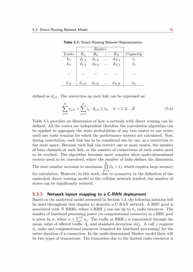
5.3. Direct Routing Network Model 79
Table 5.1: Direct Routing Network Representation
RoutesLinks R1 R2 ... RN CapacityL1 d1,1 d1,2 ... dN,1 l1L2 d1,2 d2,2 ... dN,2 l2
... ... ... ... ... ...
LK d1,K d2,K ... dN,K lK
defined as dj,k. The restriction on each link can be expressed as:
N∑j=1
xj,k =N∑j=1
ij · dj,k ≤ lk, k = 1, 2, ...K (5.4)
Table 5.1 provides an illustration of how a network with direct routing can bedefined. All the routes are independent therefore the convolution algorithm canbe applied to aggregate the state probabilities of any two routes to one route,until one route remains for which the performance metrics are calculated. Now,during convolution, each link has to be considered one by one, as a restriction tothe state space. Because each link can restrict one or more routes, the numberof busy channels at each link, or the number of connections at each routes needto be tracked. The algorithm becomes more complex since multi-dimensionalvectors need to be convolved, where the number of links defines the dimension.
The state number increases to maximumK∏k=1
(lk + 1), which requires large memory
for calculation. However, in this work, due to symmetry in the definition of theequivalent direct routing model to the cellular network studied, the number ofstates can be significantly reduced.
5.3.3 Network layout mapping to a C-RAN deploymentBased on the analytical model presented in Section 5.3, the following notation willbe used throughout this chapter to describe a C-RAN network. A BBU pool isassociated with N RRHs, where a RRH j can use up to nj radio resources. Thenumber of baseband processing power (or computational resources) in a BBU poolis given by n, where n ≤
∑N1 nj . The traffic at RRH j is represented through the
mean value of offered traffic Aj and standard deviation stdj . A call j requiresdj radio and computational resources (required for baseband processing) for theentire duration of a connection. In the multi-dimensional Markov model there willbe two types of truncations. The truncation due to the limited radio resources is
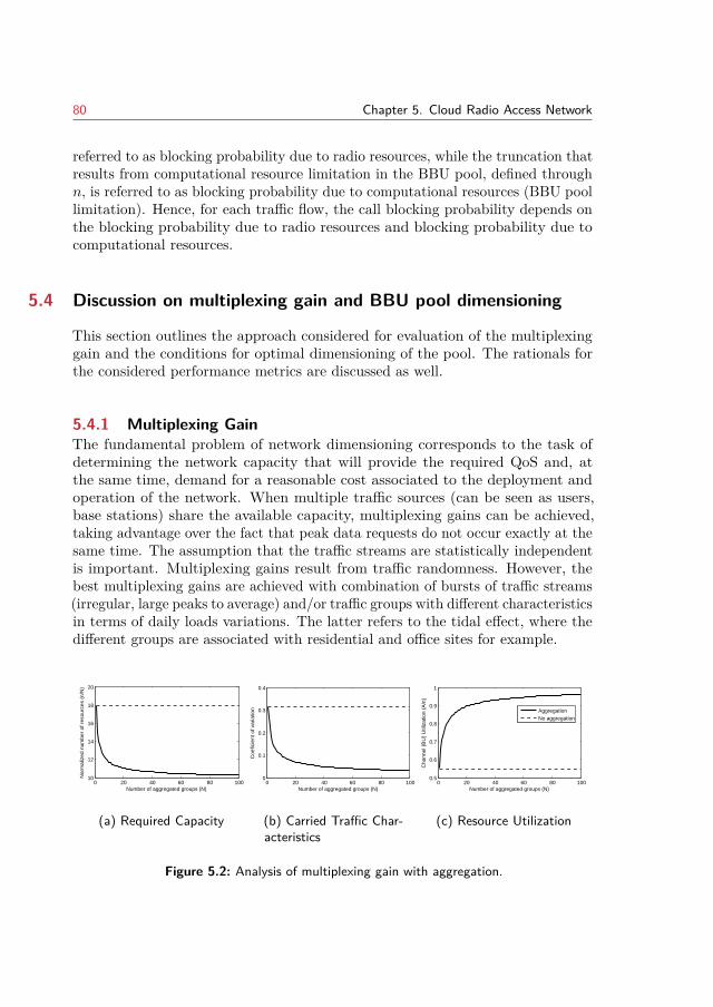
80 Chapter 5. Cloud Radio Access Network
referred to as blocking probability due to radio resources, while the truncation thatresults from computational resource limitation in the BBU pool, defined throughn, is referred to as blocking probability due to computational resources (BBU poollimitation). Hence, for each traffic flow, the call blocking probability depends onthe blocking probability due to radio resources and blocking probability due tocomputational resources.
5.4 Discussion on multiplexing gain and BBU pool dimensioning
This section outlines the approach considered for evaluation of the multiplexinggain and the conditions for optimal dimensioning of the pool. The rationals forthe considered performance metrics are discussed as well.
5.4.1 Multiplexing GainThe fundamental problem of network dimensioning corresponds to the task ofdetermining the network capacity that will provide the required QoS and, atthe same time, demand for a reasonable cost associated to the deployment andoperation of the network. When multiple traffic sources (can be seen as users,base stations) share the available capacity, multiplexing gains can be achieved,taking advantage over the fact that peak data requests do not occur exactly at thesame time. The assumption that the traffic streams are statistically independentis important. Multiplexing gains result from traffic randomness. However, thebest multiplexing gains are achieved with combination of bursts of traffic streams(irregular, large peaks to average) and/or traffic groups with different characteristicsin terms of daily loads variations. The latter refers to the tidal effect, where thedifferent groups are associated with residential and office sites for example.
0 20 40 60 80 10010
12
14
16
18
20
Number of aggregated groups (N)
Nor
mal
ized
num
ber
of r
esou
rces
(n/
N)
(a) Required Capacity
0 20 40 60 80 1000
0.1
0.2
0.3
0.4
Number of aggregated groups (N)
Coe
ficie
nt o
f var
iatio
n
(b) Carried Traffic Char-acteristics
0 20 40 60 80 1000.5
0.6
0.7
0.8
0.9
1
Number of aggregated groups (N)
Cha
nnel
(B
U)
Util
izat
ion
(A/n
)
AggregationNo aggregation
(c) Resource Utilization
Figure 5.2: Analysis of multiplexing gain with aggregation.
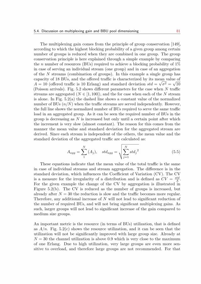
5.4. Discussion on multiplexing gain and BBU pool dimensioning 81
The multiplexing gain comes from the principle of group conservation [149],according to which the highest blocking probability of a given group among certainnumber of groups is reduced when they are combined in one group. The groupconservation principle is here explained through a simple example by comparingthe n number of resources (BUs) required to achieve a blocking probability of 1%in case of serving an individual stream (one group) and in case of an aggregationof the N streams (combination of groups). In this example a single group hascapacity of 18 BUs, and the offered traffic is characterized by its mean value ofA = 10 (offered traffic is 10 Erlang) and standard deviation std =
√σ2 =
√10
(Poisson arrivals). Fig. 5.2 shows different parameters for the case when N trafficstreams are aggregated (N ∈ [1, 100]), and the for case when each of the N streamis alone. In Fig. 5.2(a) the dashed line shows a constant value of the normalizednumber of BUs (n/N) when the traffic streams are served independently. However,the full line shows the normalized number of BUs required to serve the same trafficload in an aggregated group. As it can be seen the required number of BUs in thegroup is decreasing as N is increased but only until a certain point after whichthe increment is very slow (almost constant). The reason for this comes from themanner the mean value and standard deviation for the aggregated stream arederived. Since each stream is independent of the others, the mean value and thestandard deviation of the aggregated traffic are calculated as:
Aagg =N∑1
(Aj), stdagg =
√√√√ N∑j=1
stdj2 (5.5)
These equations indicate that the mean value of the total traffic is the samein case of individual streams and stream aggregation. The difference is in thestandard deviation, which influences the Coefficient of Variation (CV). The CVis a measure for the irregularity of a distribution and is defined as CV = std
A .For the given example the change of the CV by aggregation is illustrated inFigure 5.2(b). The CV is reduced as the number of groups is increased, butalready after N = 30 the reduction is slow and the traffic becomes more regular.Therefore, any additional increase of N will not lead to significant reduction ofthe number of required BUs, and will not bring significant multiplexing gains. Assuch, larger groups will not lead to significant increase of the gain compared tomedium size groups.
An important metric is the resource (in terms of BUs) utilization, that is definedas A/n. Fig. 5.2(c) shows the resource utilization, and it can be seen that theutilization will not be significantly improved with large group size. Already atN = 30 the channel utilization is above 0.9 which is very close to the maximumof one Erlang. Due to high utilization, very large groups are even more sen-sitive to overload, and therefore large groups are not recommended. For that
82 Chapter 5. Cloud Radio Access Network
0 10 20 30 40 50 60 70 80 90 1000
2
4
6
8
Number of aggregated groups (N)
Blo
ckin
g pr
obab
ility
(%
)
Dimensioning with E = 1%Dimensioning with Fn = 0.2Dimensioning with E = 1%Dimensioning with Fn = 0.2
Increase of offered traffic by 10%
Figure 5.3: Blocking probability dependency on group dimensioning.
reason, the tradeoff between utilization and sensitivity should be considered whendimensioning.
5.4.2 BBU pool dimensioning and multiplexing gainsThe discussion above gives insights in the possible gains in pooling the basebandprocessing resources from each BS into a centralized pool. Moreover, it givesindications on the size of such pools and the impact on the gains (in terms ofrequired BUs and their utilization) as well as on the sensitivity to traffic variations.Two approaches for BBU pool dimensioning can be considered: dimensioningwith fixed blocking probability and dimensioning with fixed improvement function.With fixed blocking probability, the dimensioning of the BBU pools is done byrestricting the time congestion to a threshold such that the number of calls thatneed to re-attempt the connection will be low. This principle was used in theexample above. As seen, this type of dimensioning can easily lead to a systemwith high utilization for large group size, but in the same time to a very sensitivesystem because it does not consider the channel utilization.
The dimensioning principle based on improvement function is also known asMoe’s principle for dimensioning. The improvement function is defined as theincrease in carried traffic when the number of channels (n) is increased by 1,Fn(A) = Y n+1(A)− Y n(A), where Y n(A) =
∑Nj=1 Y
nj (Aj). As one BU can carry
at most one Erlang, the following is correct 0 ≤ Fn(A) ≤ 1. The improvementfunction can be set to a fixed improvement value Ftarget, such that a desiredbalance between high utilization and sensitivity is be ensured. A cost requirementcan also be included in determining the optimal number of resources in thepool. Then, the improvement value depends on the cost of adding a RRH toa BBU pool - for example the cost of fiber required for the fronthaul network,computational/energy resources etc. The benefits from the increase of the carriedtraffic should also be included as income, such that Ftarget = cost
income . In this work
5.5. Multiplexing Gains for Centralized Baseband Processing 83
however, the cost and the income are not considered in order to define the valueof Ftarget.
Given the previous example, Fig. 5.3 illustrates how the blocking probabilityis influenced when the offered traffic to the aggregated group is increased by 10%.As it can be seen for small size groups, dimensioning based on blocking probabilityleads to better sensitivity in case of increase of offered traffic. The increase inthe blocking probability is lower if the group is dimensioned based on blockingprobability. However, compared to the case when the group is dimensioned basedon blocking probability, dimensioning for medium to large group size based onimprovement functions leads to increase of n (group capacity) and therefore toimproved sensitivity to traffic increase.
Therefore, if medium to large groups are considered in a BBU pool, dimen-sioning based on improvement function is more appropriate. Based on the im-provement function, the required resources nBBUpool can be determined such thatFn(A)|n=nBBUpool ≤ Ftarget. If there are N individual groups of capacity nRRHthen the multiplexing gain achieved by pooling resources can be quantified by:
MGc−ran =∑N
1 nRRHnBBUpool
(5.6)
Equivalent to eq. (5.6) is the percentage of savings that can be achieved bythe pooling and can be expressed as:
BBUsavec−ran =∑N
1 (nRRH)− nBBUpool∑N1 nRRH
(5.7)
5.5 Multiplexing Gains for Centralized Baseband Processing
In [61], the authors model the dynamics of the BBU pool with a multi-dimensionalMarkov model. The work shows that the system parameters such as pool size,QoS requirements at the radio part, and the traffic load have impact on thesystem design. In their analysis, all the cells that are associated in a common poolof BBUs, have the same characteristics: size (BS transmission power), type oftraffic and QoS demand. Therefore, the proposed model cannot be directly usedif HetNets are analyzed. By extending the single link model with the networkmodel as described in Section 5.3, a direct routing equivalent to a C-RAN can bederived. The model obtained can be used to estimate the performance metricsfor a C-RAN architecture that can include cells with different size (as number ofradio resources), cells with different traffic profiles (smooth, bursty and random),services that have different QoS requirements (as a minimum number of resources
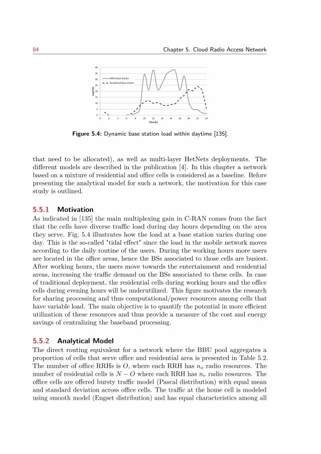
84 Chapter 5. Cloud Radio Access Network
0
5
10
15
20
25
30
35
40
0 2 4 6 8 10 12 14 16 18 20 22 24
Load
(%
)
Time (h)
Office Base Station
Residential Base station
Figure 5.4: Dynamic base station load within daytime [135].
that need to be allocated), as well as multi-layer HetNets deployments. Thedifferent models are described in the publication [4]. In this chapter a networkbased on a mixture of residential and office cells is considered as a baseline. Beforepresenting the analytical model for such a network, the motivation for this casestudy is outlined.
5.5.1 MotivationAs indicated in [135] the main multiplexing gain in C-RAN comes from the factthat the cells have diverse traffic load during day hours depending on the areathey serve. Fig. 5.4 illustrates how the load at a base station varies during oneday. This is the so-called "tidal effect" since the load in the mobile network movesaccording to the daily routine of the users. During the working hours more usersare located in the office areas, hence the BSs associated to those cells are busiest.After working hours, the users move towards the entertainment and residentialareas, increasing the traffic demand on the BSs associated to these cells. In caseof traditional deployment, the residential cells during working hours and the officecells during evening hours will be underutilized. This figure motivates the researchfor sharing processing and thus computational/power resources among cells thathave variable load. The main objective is to quantify the potential in more efficientutilization of these resources and thus provide a measure of the cost and energysavings of centralizing the baseband processing.
5.5.2 Analytical ModelThe direct routing equivalent for a network where the BBU pool aggregates aproportion of cells that serve office and residential area is presented in Table 5.2.The number of office RRHs is O, where each RRH has no radio resources. Thenumber of residential cells is N −O where each RRH has nr radio resources. Theoffice cells are offered bursty traffic model (Pascal distribution) with equal meanand standard deviation across office cells. The traffic at the home cell is modeledusing smooth model (Engset distribution) and has equal characteristics among all
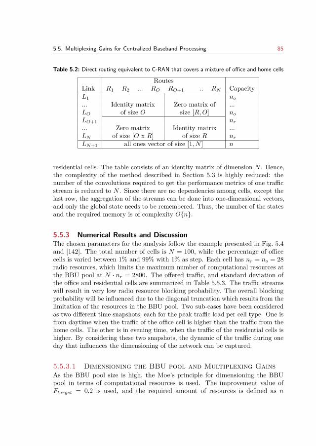
5.5. Multiplexing Gains for Centralized Baseband Processing 85
Table 5.2: Direct routing equivalent to C-RAN that covers a mixture of office and home cells
RoutesLink R1 R2 ... RO RO+1 .. RN CapacityL1
Identity matrixof size O
Zero matrix ofsize [R,O]
no... ...LO noLO+1
Zero matrixof size [O x R]
Identity matrixof size R
nr... ...LN nrLN+1 all ones vector of size [1, N ] n
residential cells. The table consists of an identity matrix of dimension N . Hence,the complexity of the method described in Section 5.3 is highly reduced: thenumber of the convolutions required to get the performance metrics of one trafficstream is reduced to N . Since there are no dependencies among cells, except thelast row, the aggregation of the streams can be done into one-dimensional vectors,and only the global state needs to be remembered. Thus, the number of the statesand the required memory is of complexity On.
5.5.3 Numerical Results and DiscussionThe chosen parameters for the analysis follow the example presented in Fig. 5.4and [142]. The total number of cells is N = 100, while the percentage of officecells is varied between 1% and 99% with 1% as step. Each cell has nr = no = 28radio resources, which limits the maximum number of computational resources atthe BBU pool at N · nr = 2800. The offered traffic, and standard deviation ofthe office and residential cells are summarized in Table 5.5.3. The traffic streamswill result in very low radio resource blocking probability. The overall blockingprobability will be influenced due to the diagonal truncation which results from thelimitation of the resources in the BBU pool. Two sub-cases have been consideredas two different time snapshots, each for the peak traffic load per cell type. One isfrom daytime when the traffic of the office cell is higher than the traffic from thehome cells. The other is in evening time, when the traffic of the residential cells ishigher. By considering these two snapshots, the dynamic of the traffic during oneday that influences the dimensioning of the network can be captured.
5.5.3.1 Dimensioning the BBU pool and Multiplexing GainsAs the BBU pool size is high, the Moe’s principle for dimensioning the BBUpool in terms of computational resources is used. The improvement value ofFtarget = 0.2 is used, and the required amount of resources is defined as n
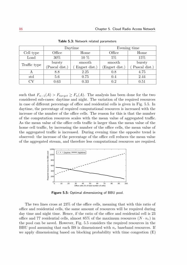
86 Chapter 5. Cloud Radio Access Network
Table 5.3: Network related parameters
Daytime Evening timeCell type Office Home Office HomeLoad 30% 10 % 5% 15%
Traffic type bursty(Pascal dist.)
smooth( Engset dist.)
smooth(Engset dist.)
bursty( Pascal dist.)
A 8.8 2.25 0.8 4.75std 5.6 0.75 0.4 2.44CV 0.63 0.33 0.2 0.51
such that Fn−1(A) > Ftarget ≥ Fn(A). The analysis has been done for the twoconsidered sub-cases: daytime and night. The variation of the required resourcesin case of different percentage of office and residential cells is given in Fig. 5.5. Indaytime, the percentage of required computational resources is increased with theincrease of the number of the office cells. The reason for this is that the numberof the computation resources scales with the mean value of aggregated traffic.As the mean value of the office cells traffic is larger than the mean value of thehome cell traffic, by increasing the number of the office cells, the mean value ofthe aggregated traffic is increased. During evening time the opposite trend isobserved: the increase of the percentage of the office cell reduces the mean valueof the aggregated stream, and therefore less computational resources are required.
0 10 20 30 40 50 60 70 80 90 1000
200
400
600
800
1000
1200
Office cells (% of total number of cells)
Req
uire
d re
sour
ces
in th
e B
BU
poo
l
Daytime Nighttime
Figure 5.5: Optimal dimensioning of BBU pool.
The two lines cross at 23% of the office cells, meaning that with this ratio ofoffice and residential cells, the same amount of resources will be required duringday time and night time. Hence, if the ratio of the office and residential cell is 23office and 77 residential cells, almost 85% of the maximum resources (N · nr) inthe pool can be saved. However, Fig. 5.5 considers the required resources in theBBU pool assuming that each BS is dimensioned with nr baseband resources. Ifwe apply dimensioning based on blocking probability with time congestion (E)
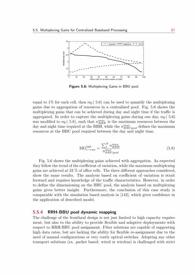
5.5. Multiplexing Gains for Centralized Baseband Processing 87
0 10 20 30 40 50 60 70 80 90 1001
1.5
2
2.5
3
3.5
Office cells (% of total number of cells)
Mul
tiple
Gai
n
Daytime Nighttime 24 h
Figure 5.6: Multiplexing Gains in BBU pool.
equal to 1% for each cell, then eq.( 5.6) can be used to quantify the multiplexinggains due to aggregation of resources in a centralized pool. Fig. 5.6 shows themultiplexing gains that can be achieved during day and night time if the traffic isaggregated. In order to capture the multiplexing gains during one day, eq.( 5.6)was modified to eq.( 5.8), such that nmaxRRH is the maximum resources between theday and night time required at the RRH, while the nmaxBBUpool defines the maximumresources at the BBU pool required between the day and night time.
MG24hc−ran =
∑N1 nmaxRRH
nmaxBBUpool
(5.8)
Fig. 5.6 shows the multiplexing gains achieved with aggregation. As expectedthey follow the trend of the coefficient of variation, while the maximum multiplexinggains are achieved at 23 % of office cells. The three different approaches considered,show the same results. The analysis based on coefficient of variation is straitforward and requires knowledge of the traffic characteristics. However, in orderto define the dimensioning on the BBU pool, the analysis based on multiplexinggains gives better insight. Furthermore, the conclusion of this case study iscomparable with the simulation based analysis in [142], which gives confidence inthe application of described model.
5.5.4 RRH-BBU pool dynamic mappingThe challenge of the fronthaul design is not just limited to high capacity require-ment, but also to the ability to provide flexible and adaptive deployments withrespect to RRH-BBU pool assignment. Fiber solutions are capable of supportinghigh data rates, but are lacking the ability for flexible re-assignment due to theneed of manual configurations or very costly optical switches. Adopting any othertransport solutions (ex. packet based: wired or wireless) is challenged with strict
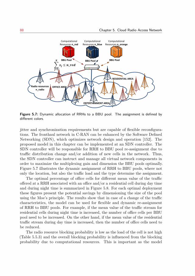
88 Chapter 5. Cloud Radio Access Network
ENTERTAINMENT AREA
OFFICE AREA
BBU Pool BBU PoolBBU Pool
Radio resources n_radio
RESIDENTIAL AREA
Computational Resources n_red
Computational Resources n_blue
Computational Resources n_orange
𝒙𝒋
𝑵
𝒋=𝟏
≤ 𝒏_𝒓𝒆𝒅
Figure 5.7: Dynamic allocation of RRHs to a BBU pool. The assignment is defined bydifferent colors.
jitter and synchronization requirements but are capable of flexible reconfigura-tions. The fronthaul network in C-RAN can be enhanced by the Software DefinedNetworking (SDN), which optimizes network design and operation [152]. Theproposed model in this chapter can be implemented at an SDN controller. TheSDN controller will be responsible for RRH to BBU pool re-assignment due totraffic distribution change and/or addition of new cells in the network. Thus,the SDN controller can instruct and manage all virtual network components inorder to maximize the multiplexing gain and dimension the BBU pools optimally.Figure 5.7 illustrates the dynamic assignment of RRH to BBU pools, where notonly the location, but also the traffic load and the type determine the assignment.
The optimal percentage of office cells for different mean value of the trafficoffered at a RRH associated with an office and/or a residential cell during day timeand during night time is summarized in Figure 5.8. For each optimal deploymentthese figures present the potential savings by dimensioning the size of the poolusing the Moe’s principle. The results show that in case of a change of the trafficcharacteristics, the model can be used for flexible and dynamic re-assignmentof RRH to BBU pools. For example, if the mean value of the traffic stream forresidential cells during night time is increased, the number of office cells per BBUpool need to be increased. On the other hand, if the mean value of the residentialtraffic stream during day time is increased, then the number of office cells need tobe reduced.
The radio resource blocking probability is low as the load of the cell is not high(Table 5.5.3) and the overall blocking probability is influenced from the blockingprobability due to computational resources. This is important as the model
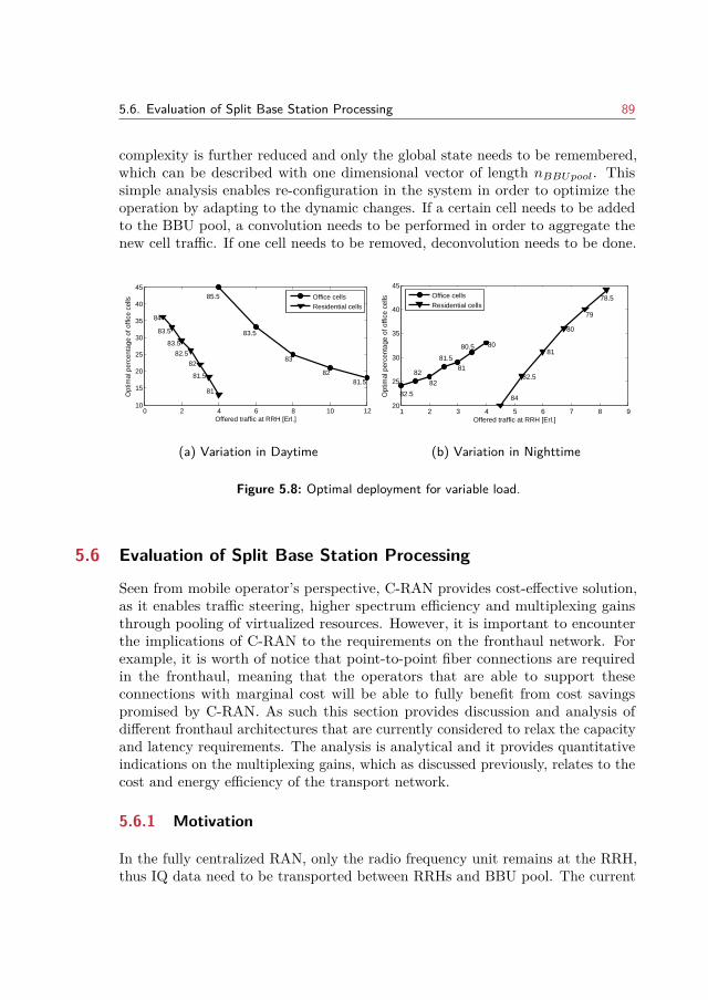
5.6. Evaluation of Split Base Station Processing 89
complexity is further reduced and only the global state needs to be remembered,which can be described with one dimensional vector of length nBBUpool. Thissimple analysis enables re-configuration in the system in order to optimize theoperation by adapting to the dynamic changes. If a certain cell needs to be addedto the BBU pool, a convolution needs to be performed in order to aggregate thenew cell traffic. If one cell needs to be removed, deconvolution needs to be done.
0 2 4 6 8 10 1210
15
20
25
30
35
40
4585.5
83.5
83
8281.5
84
83.5
83.5
82.5
82
81.5
81
Offered traffic at RRH [Erl.]
Opt
imal
per
cent
age
of o
ffice
cel
ls
Office cellsResidential cells
(a) Variation in Daytime
1 2 3 4 5 6 7 8 920
25
30
35
40
45
82.5
82
82
81.581
80.5 80
84
82.5
81
80
79
78.5
Offered traffic at RRH [Erl.]
Opt
imal
per
cent
age
of o
ffice
cel
ls
Office cellsResidential cells
(b) Variation in Nighttime
Figure 5.8: Optimal deployment for variable load.
5.6 Evaluation of Split Base Station Processing
Seen from mobile operator’s perspective, C-RAN provides cost-effective solution,as it enables traffic steering, higher spectrum efficiency and multiplexing gainsthrough pooling of virtualized resources. However, it is important to encounterthe implications of C-RAN to the requirements on the fronthaul network. Forexample, it is worth of notice that point-to-point fiber connections are requiredin the fronthaul, meaning that the operators that are able to support theseconnections with marginal cost will be able to fully benefit from cost savingspromised by C-RAN. As such this section provides discussion and analysis ofdifferent fronthaul architectures that are currently considered to relax the capacityand latency requirements. The analysis is analytical and it provides quantitativeindications on the multiplexing gains, which as discussed previously, relates to thecost and energy efficiency of the transport network.
5.6.1 Motivation
In the fully centralized RAN, only the radio frequency unit remains at the RRH,thus IQ data need to be transported between RRHs and BBU pool. The current
90 Chapter 5. Cloud Radio Access Network
interface definition, (CPRI or OBSAI), yields for high bandwidth and low latencyrequirements in the fronthaul infrastructure which challenges the overall benefits ofC-RAN. For example in case of CPRI fronthaul interface, for a 20MHz bandwidthand 2x2 MIMO antenna system, the bandwidth required by the fronthaul linkbetween the RRH and BBU pool in one sector is 2457.6 Mbps, where only 150Mbpsis offered to a single cell users on the air interface [67]. The maximum allowedlatency is in order of few microseconds. Additionally, the CPRI interface assumespoint-to-point connections, which makes it inflexible with respect to assignmentof RRH to BBU pool.
As the complete baseband processing is placed at the centralized pool, thefronthaul interface is independent of the traffic load and dependent of the numberof antennas used, which together highly reduce the transport efficiency. Withrespect to the technologies on the road towards the 5th generation, such as ultradense network deployments and massive MIMO, even with compression in place,the capacity needed in the fronthaul will further obstruct the advantages of theC-RAN architecture. The Small Cell Forum [67], iJoin Project [68], and ChinaMobile [69] have identified that support for flexible functional split in the LTEprocessing is required in order to relax the requirements on the transport networkbut still allow cost-effective deployments through centralization and cloudification.
5.6.2 Functional Splits in Baseband Processing
The main goal of introducing the functional split in the baseband processing isto relax the requirements on the fronthaul network such that alternative, cost-effective transport network, such as Ethernet/Internet Protocol, MultiprotocolLabel Switching logical networks over microwave, shared fiber and Gigabit passiveOPtical networks (GPON) will be able to support the requirements of the fronthaulinfrastructure [70]. The upcoming fronthaul interface based on such a split shouldaim at realizing the benefits of centralization and cloud computation at highestpossible level. At the same time the statistical multiplexing on the links shouldbe increased, such that the bandwidth required should be dependent on the loadas much as possible. Extensive analysis of most promising fronthaul functionalsplits is given in: [70], [69], [67]. In the work presented by this section, the focusis placed on the two splits, refereed to as: UE-Cell split and PDCP-RLC split.These two splits are illustrated in Fig. 5.9. The BB-RF split is included in thefigure as a fully centralized C-RAN, where the complete baseband functionalityis placed in the pool. The main characteristics of the UE-Cell and PDCP-RLCsplits are:
UE-Cell split: With this split, the physical layer is separated just before(after) resource (de)mapping in downlink (uplnik) direction. This means that theuser data (shared data channels) together with the control channels can be sent
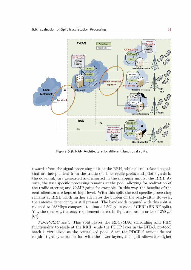
5.6. Evaluation of Split Base Station Processing 91
PDCP
RLC/MAC
PHY
RLC/MAC
PHY
RLC/MAC
PHY
BBU pool
PHY
I/Q
I/Q
UE-Cell Split
Limited fronthaul capacity
BB-RF Split
PDCP-RLC Split
Cell LevelPRB Scheduling
frequency
tim
e
Coordinated CellPRB Scheduling
frequency
tim
e
RLC/MAC
I/Q
RLC/MAC
PHYI/Q
RRC/PDCPX2
C-RAN
RAN
X2 dependentAnd Cell isolatedPRB Scheduling
frequency
tim
e
S1
Core Network
S1
backhaul
Distributed BS RRH
RRH
RRH
RRHbaseband processing
baseband processing
baseband processing
Active layer
Inactive layer
Figure 5.9: RAN Architecture for different functional splits.
towards/from the signal processing unit at the RRH, while all cell related signalsthat are independent from the traffic (such as cyclic prefix and pilot signals inthe downlink) are generated and inserted in the mapping unit at the RRH. Assuch, the user specific processing remains at the pool, allowing for realization ofthe traffic steering and CoMP gains for example. In this way, the benefits of thecentralization are kept at high level. With this split the cell specific processingremains at RRH, which further alleviates the burden on the bandwidth. However,the antenna dependency is still present. The bandwidth required with this split isreduced to 933Mbps compared to almost 2,5Gbps in case of CPRI (BB-RF split).Yet, the (one way) latency requirements are still tight and are in order of 250 µs[67].
PDCP-RLC split: This split leaves the RLC/MAC scheduling and PHYfunctionality to reside at the RRH, while the PDCP layer in the LTE-A protocolstack is virtualized at the centralized pool. Since the PDCP functions do notrequire tight synchronization with the lower layers, this split allows for higher
92 Chapter 5. Cloud Radio Access Network
latencies in the order of 30ms [67]. Furthermore, the functionality of the PDCPlayer can be generalized as to allow multi-standard support, especially for anyupcoming air interface technology [153]. The bandwidth requirements are reducedto 151Mbps [67]. However, this split gives marginal gains with respect to cloudcomputing and virtualization compared to fully integrated eNB. Furthermore, thissplits limits the possibility for joint PHY and MAC processing, which decreasesthe possible gains in spectral efficiency.
A discussion whether the functional split should be defined statically, per cell,or dynamically per bearer is also important decision that impact the design on thefronthaul network [154]. If the flexibility is introduced per user/bearer within thesame cell, the scheduler design will be impacted, especially if PDCP-RLC split isconsidered. In such a case the decisions on scheduling need to be made partiallyat the remote end and partially at the pool. In general, the criteria that influencethe split decision can be summarized as follows:
- Overall traffic load in the network and quality of service (bandwidth andlatency requirements) being provided to the end user together,
- The need for joint processing on the physical or MAC layer,
- Status of the fronthaul links (capacity, utilization and latency),
- Computational/energy resources occupied at the RRH and the BBU pool.
5.6.3 Case study on Fronthaul Network
For heterogeneous cases, when some of the cells are backhauled as traditionalRAN, or with C-RAN with flexible processing split, it is important to analyze thepossible multiplexing gains and how the total costs of such a network depend onthe split decision. In that line, the following work provides a quantitative analysisfor such a heterogeneous network. In particular, heterogeneous functional split inthe fronthaul interface is considered with dynamic split per traffic flow. With thisassumption, a portion of traffic per RRH that is carried with a specific split canbe defined, which introduces symmetry in the RRH definition of the analyticalmodel and hence it simplifies the analysis1.
The case study of heterogeneous case with two splits, UE-Cell and PDCP-RLC,is illustrated in Fig. 5.10. A network of N cells is considered, and each cell haslimited radio and baseband processing (computational) resources, denoted as nrand np. The pooled (radio and processing) resources are defined by nrBBU andnpBBU , while nrRRH and npRRH define the resources that are not centralized and
1Alternatively, the split can be defined per cell, where a portion of RRHs that are connectedvia specific split is defined.
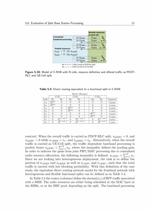
5.6. Evaluation of Split Base Station Processing 93
Remote resources at each cell
Centralized baseband processing
nrBBU > N ∙ (nr-nrRRH)
npBBU < N ∙ (np-npRRH)
nrRRH
npRRH
nr-nrRRH
np-npRRH
nrRRH
npRRH
nr-nrRRH
np-npRRH
nrRRH
npRRH
nr-nrRRH
np-npRRH
Pooled resources:Cell 1
Cell 2Cell N
. . .
Traffic carried as UE-Cell SplitTraffic carried as PDCP-RLC Split
Figure 5.10: Model of C-RAN with N cells, resource definition and offered traffic as PDCP-RLC and UE-Cell split.
Table 5.4: Direct routing equivalent to a functional split in C-RANRoute (Stream)
Cell1 Cell2 ... CellNLink RP RU RP RU RP RU CapacityLA dpdcpp 0 0 0 0 0 npRRHLB dpdcpr 0 0 0 0 0 nrRRHLA 0 0 dpdcpp 0 0 0 npRRHLB 0 0 dpdcpr 0 0 0 nrRRHLA 0 0 0 0 dpdcpp 0 npRRHLB 0 0 0 0 dpdcpr 0 nrRRHLC 0 due−cellp 0 due−cellp 0 due−cellp npBBULD 0 due−cellr 0 due−cellr 0 due−cellr nrBBU
reserved. When the overall traffic is carried as PDCP-RLC split, npBBU = 0, andnpBBU = 0 while nrRRH = nr, and npRRH = np. Alternatively, when the overalltraffic is carried as UE-Cell split, the traffic dependent baseband processing ispooled, hence npBBU <
∑Ni=1 np, where the inequality defines the pooling gain.
In order to indicate the gains from joint PHY/MAC processing due to centralizedradio resource allocation, the following inequality is defined: nrBBU >
∑Ni=1 nr.
Since we are looking into heterogeneous deployment, the task is to define theportion of nrRRH and npRRH as well as nrBBU and nrBBU , such that the totaltraffic is carried with low blocking probability. With this definition of the casestudy, the equivalent direct routing network model for the fronthaul network withheterogeneous and flexible functional splits can be defined as in Table 5.4.
In Table 5.4 the routes (columns) define the stream(s) j of BPP traffic associatedwith a RRH. The radio resources are either being scheduled at the MAC layer atthe RRHs, or at the BBU pool, depending on the split. The baseband processing
94 Chapter 5. Cloud Radio Access Network
power required for these radio resources is reserved in the RRH, or the BBUpool, correspondingly to the assigned radio resources. The limited amount ofradio resources and processing power available need to be considered during eachconvolution step, and in this case they are represented by the link-restrictions. Asthe performance metrics in case of heterogeneous functional splits are evaluated,the resources (both radio and processing) required at the BBU pool and theRRH for each stream (route) have to be determined. The route RP defines themean offered traffic Apdcpj and the standard deviation stdpdcpj of the traffic thatis carried in the fronthaul network through the PDCP-RLC interface at the j-thcell. The route RU defines the same characteristics (Aue−cellj and stdue−cellj ) forthe traffic that is carried as UE-Cell split at the j-th cell. The capacity definestotal available resources, both radio and processing, which yields the followingrestrictions. Link LA define the restrictions due to the available PRBs at eachRRH (nrRRH), while link LB defines the limited processing possibilities at theRRH, defined through npRRH . Link LC , and LD define the restrictions due to thetotal available radio and processing resources at the BBU pool, defined as nrBBUand npBBU respectively.
5.6.4 Case Study Numerical Results and DiscussionFor the numerical analysis N = 100 cells are considered, each with total offeredtraffic of A = 8Erl. and arrival rates with Poisson distribution. In order to keepthe studies manageable Poisson arrivals with single-slot traffic (dxp = dxr = 1, x ∈pdcp, ue− cell) are assumed. At a fixed offered traffic, the percentage of totaltraffic that is carried as PDCP-RLC split is varied from 0 to 100%, with a stepof 10%. This way the network becomes heterogeneous, where the deployment ispartially implemented as PDCP-RLC split and partially as UE-Cell split. Foreach split percentage, we first derive the minimum amount of radio (nrRRH) andprocessing resources (npRRH) required at the RRH, such that the carried trafficis equal to the offered traffic (traffic congestion below 1%). Then the resourcesat the BBU pool (npBBU ) are determined such that the total offered traffic iscarried by the network. At each split the following key performance indicators arequantified: multiplexing gains at the BBU pool, resource saving at the fronthaullinks and radio resource utilizations. Based on eq. 5.6, the multiplexing gain forthe computational resources at the BBU pool is defined as:
MGBBU−H =∑N
1 nr
npBBU +∑N
1 npRRH(5.9)
where nr represent the maximum processing units available at a RRH in a(traditional) RAN architecture. Only the multiplexing gains that come from thelayers below PDCP are considered, as all the gains of centralizing the PDCP layerare present for both functional splits.
5.6. Evaluation of Split Base Station Processing 95
On the fronhaul network, the traffic from the UE-Cell split will require largerbandwidth as 933/151Mbps ∼ 6. It is considered that the traffic on the links withthe UE-Cell split still remain Poisson, as it should follows the users demand, but itrequires six time larger bandwidth on the links than for the case with PDCP-RLCsplit. Therefore, the offered traffic on the fronthaul link can be dimensionedas Aue−cellj,FH = Aue−cellj · dj,FH , where dj,FH = 6. The traffic coming from thePDCP-RLC split will be the same, Apdcpj,FH = Apdcpj ·dpdcpj,FH , where dpdcpj,FH = 1. Usingthe same approach as in the BBU pool, the multiplexing gains in the fronthaulnetwork can be defined as:
BGgain−H = nmaxFH
nsplit%FH
(5.10)
where nsplit%FH represent the required amount of resources (bandwidth units)for a certain split percentage, and in case all the traffic is multiplexed withinthe fronthaul network. The maximum number of resources in the fronthaul isrequired in case all the traffic is carried as UE-Cell split, and that is denoted bynmaxFH . Alternatively, the multiplexing gains due to shared capacity in the fronhaulnetwork by all RRHs can be defined as (similar to eq.( 5.6)):
MGFH−H =∑N
1 nsplit%FH,cell
nsplit%FH
(5.11)
where nsplit%FH,cell denotes the capacity required by a single cell in order to carrythe traffic with very low blocking probability.
Implementing multi-cell cooperation, such as CoMP, leads to increased spectralefficiency, especially at the cell edges, where interference is reduced and even moreused as complementary signal in case of joint transmission. In order to indicatethe effects of multi-cell cooperation, a percentage of radio resource sharing amongcells (sharing_pct) is introduced. Then, the radio resource utilization can bedefined through the following equation:
PRButil = carried_trafficnrCell + nrBBU
(5.12)
where nrBBU = (nrCell−nrRRH) · sharing_pct, and nrCell are the radio resourceavailable at the RRH in case all traffic is carried as PDCP-RLC split. The morepossibility there exist for multi-cell cooperation, the PRB are better utilized andhence, less PRBs are needed in order to carry the same traffic volume. Since weconsider that the total offered traffic is carried, carried_traffic = A = 8Erl.,while sharing_pct = 30% to reflect for example CoMP gains [155].
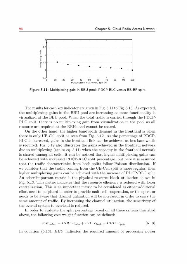
96 Chapter 5. Cloud Radio Access Network
0 10 20 30 40 50 60 70 80 90 1000.5
1
1.5
2
2.5
3
Percentage of PDCP−RLC Split (%)
Mul
tiple
Gai
n
Figure 5.11: Multiplexing gain in BBU pool: PDCP-RLC versus BB-RF split.
The results for each key indicator are given in Fig. 5.11 to Fig. 5.13. As expected,the multiplexing gains in the BBU pool are increasing as more functionality isvirtualized at the BBU pool. When the total traffic is carried through the PDCP-RLC split, there is no multiplexing gain from virtualization in the pool as allresource are required at the RRHs and cannot be shared.
On the other hand, the higher bandwidth demand in the fronthaul is whenthere is only UE-Cell split as seen from Fig. 5.12. As the percentage of PDCP-RLC is increased, gains in the fronthaul link can be achieved as less bandwidthis required. Fig. 5.12 also illustrates the gains achieved in the fronthaul networkdue to multiplexing (acc to eq. 5.11) when the capacity in the fronthaul networkis shared among all cells. It can be noticed that higher multiplexing gains canbe achieved with increased PDCP-RLC split percentage, but here it is assumedthat the traffic characteristics from both splits follow Poisson distribution. Ifwe consider that the traffic coming from the UE-Cell split is more regular, thenhigher multiplexing gains can be achieved with the increase of PDCP-RLC split.An other important metric is the physical resource block utilization shown inFig. 5.13. This metric indicates that the resource efficiency is reduced with lowercentralization. This is an important metric to be considered as either additionaleffort need to be placed in order to provide multi-cell cooperation, or the operatorneeds to be aware that channel utilization will be increased, in order to carry thesame amount of traffic. By increasing the channel utilization, the sensitivity ofthe overall system to overload is reduced.
In order to evaluate the split percentage based on all three criteria describedabove, the following cost weight function can be defined:
costvalue = BBU · cbbu + FH · clink + PRB · cprb (5.13)
In equation (5.13), BBU indicates the required amount of processing power
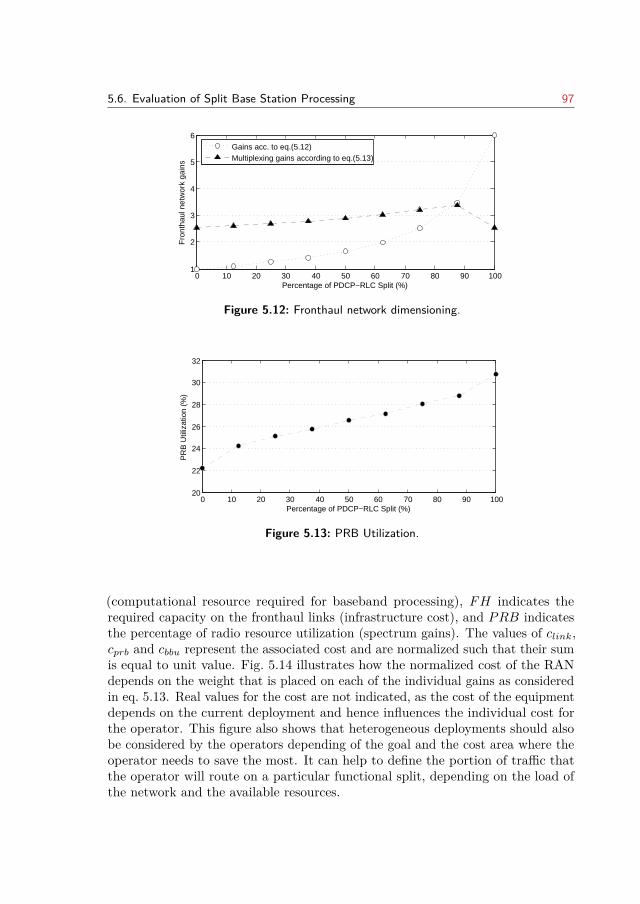
5.6. Evaluation of Split Base Station Processing 97
0 10 20 30 40 50 60 70 80 90 1001
2
3
4
5
6
Percentage of PDCP−RLC Split (%)
Fro
ntha
ul n
etw
ork
gain
s
Gains acc. to eq.(5.12)Multiplexing gains according to eq.(5.13)
Figure 5.12: Fronthaul network dimensioning.
0 10 20 30 40 50 60 70 80 90 10020
22
24
26
28
30
32
Percentage of PDCP−RLC Split (%)
PR
B U
tiliz
atio
n (%
)
Figure 5.13: PRB Utilization.
(computational resource required for baseband processing), FH indicates therequired capacity on the fronthaul links (infrastructure cost), and PRB indicatesthe percentage of radio resource utilization (spectrum gains). The values of clink,cprb and cbbu represent the associated cost and are normalized such that their sumis equal to unit value. Fig. 5.14 illustrates how the normalized cost of the RANdepends on the weight that is placed on each of the individual gains as consideredin eq. 5.13. Real values for the cost are not indicated, as the cost of the equipmentdepends on the current deployment and hence influences the individual cost forthe operator. This figure also shows that heterogeneous deployments should alsobe considered by the operators depending of the goal and the cost area where theoperator needs to save the most. It can help to define the portion of traffic thatthe operator will route on a particular functional split, depending on the load ofthe network and the available resources.
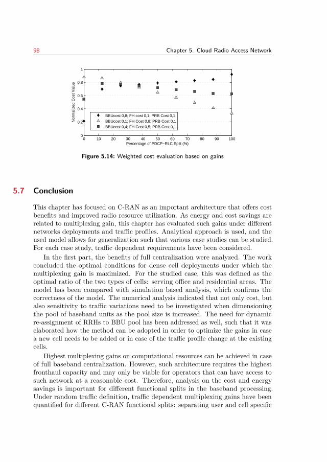
98 Chapter 5. Cloud Radio Access Network
0 10 20 30 40 50 60 70 80 90 1000
0.2
0.4
0.6
0.8
1
Percentage of PDCP−RLC Split (%)
Nor
mal
ized
Cos
t Val
ue
BBUcost 0,8; FH cost 0,1; PRB Cost 0,1BBUcost 0,1; FH Cost 0,8; PRB Cost 0,1BBUcost 0,4; FH Cost 0,5; PRB Cost 0,1
Figure 5.14: Weighted cost evaluation based on gains
5.7 Conclusion
This chapter has focused on C-RAN as an important architecture that offers costbenefits and improved radio resource utilization. As energy and cost savings arerelated to multiplexing gain, this chapter has evaluated such gains under differentnetworks deployments and traffic profiles. Analytical approach is used, and theused model allows for generalization such that various case studies can be studied.For each case study, traffic dependent requirements have been considered.
In the first part, the benefits of full centralization were analyzed. The workconcluded the optimal conditions for dense cell deployments under which themultiplexing gain is maximized. For the studied case, this was defined as theoptimal ratio of the two types of cells: serving office and residential areas. Themodel has been compared with simulation based analysis, which confirms thecorrectness of the model. The numerical analysis indicated that not only cost, butalso sensitivity to traffic variations need to be investigated when dimensioningthe pool of baseband units as the pool size is increased. The need for dynamicre-assignment of RRHs to BBU pool has been addressed as well, such that it waselaborated how the method can be adopted in order to optimize the gains in casea new cell needs to be added or in case of the traffic profile change at the existingcells.
Highest multiplexing gains on computational resources can be achieved in caseof full baseband centralization. However, such architecture requires the highestfronthaul capacity and may only be viable for operators that can have access tosuch network at a reasonable cost. Therefore, analysis on the cost and energysavings is important for different functional splits in the baseband processing.Under random traffic definition, traffic dependent multiplexing gains have beenquantified for different C-RAN functional splits: separating user and cell specific
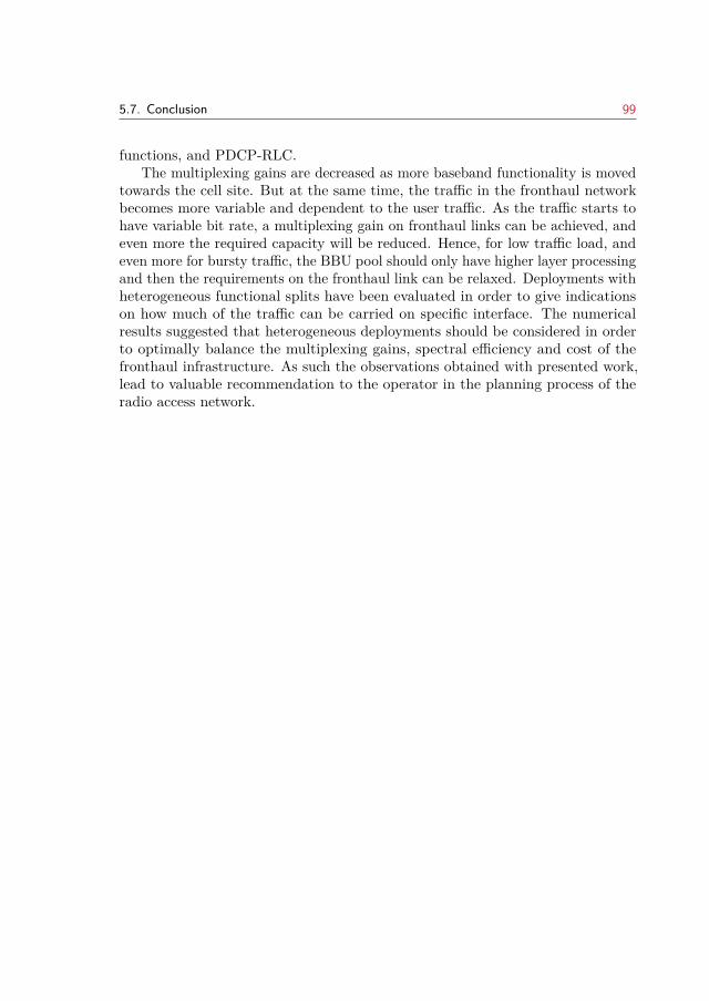
5.7. Conclusion 99
functions, and PDCP-RLC.The multiplexing gains are decreased as more baseband functionality is moved
towards the cell site. But at the same time, the traffic in the fronthaul networkbecomes more variable and dependent to the user traffic. As the traffic starts tohave variable bit rate, a multiplexing gain on fronthaul links can be achieved, andeven more the required capacity will be reduced. Hence, for low traffic load, andeven more for bursty traffic, the BBU pool should only have higher layer processingand then the requirements on the fronthaul link can be relaxed. Deployments withheterogeneous functional splits have been evaluated in order to give indicationson how much of the traffic can be carried on specific interface. The numericalresults suggested that heterogeneous deployments should be considered in orderto optimally balance the multiplexing gains, spectral efficiency and cost of thefronthaul infrastructure. As such the observations obtained with presented work,lead to valuable recommendation to the operator in the planning process of theradio access network.

100
CHAPTER 6Resource Sharing Strategies for
Mobile Operators
C-RAN, SDN and Network Function Virtualisation (NFV) are becoming paramounttechnologies, each bringing significant benefits for the future mobile networks.Seen from a broader view, these technologies are enablers for dynamic resourcesharing both, at the spectrum and the infrastructure level. The opportunities fromdynamic sharing have been identified by both, the academia and the industry asan important step towards reduction of the capital and operational expendituresrelated to the mobile networks. However, dynamic resource sharing requirescareful analysis of the benefits for the entire system and, moreover, the effects andimplications on each partner that enters a sharing agreement. With respect tothis challenge, the work presented in this chapter investigates strategies for activeresource sharing of the radio access network between operators, and introducesan analysis the individual benefits depending on the sharing degree. The modelused to assess the sharing strategies is based on multidimensional loss systems andnetworks with direct routing (presented in the previous chapter), while blockingprobability is considered as a performance metric.
This chapter starts with a introduction that outlines the motivations anddefines the objectives of the study. The up to date work related to sharing ofresources in mobile networks is presented in Section 6.2 .The implications of shar-ing radio resources locally, within a single cell, are analyzed in Section 6.3, whileSection 6.4 studies resource sharing strategies for mobile operators on a networklevel. The conclusions drawn from this study are summarized in Secton 6.5.
Note: This chapter is based on publication [5]. The text has been revised andappropriately modified for the purpose of this chapter. A copyright permissionfrom IEEE is enclosed.
101
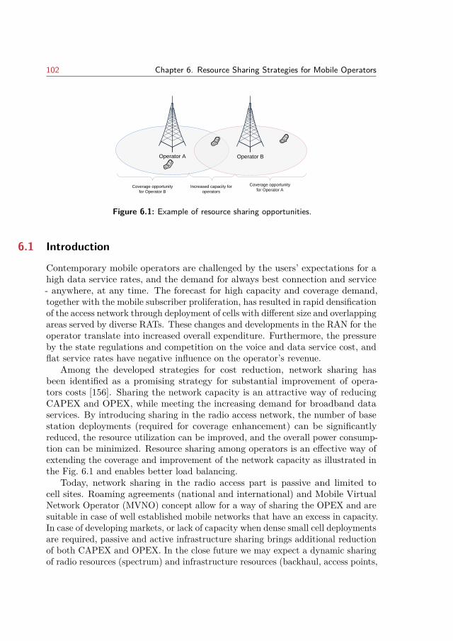
102 Chapter 6. Resource Sharing Strategies for Mobile Operators
Operator A Operator B
Coverage opportunity
for Operator B
Coverage opportunity
for Operator AIncreased capacity for
operators
Figure 6.1: Example of resource sharing opportunities.
6.1 Introduction
Contemporary mobile operators are challenged by the users’ expectations for ahigh data service rates, and the demand for always best connection and service- anywhere, at any time. The forecast for high capacity and coverage demand,together with the mobile subscriber proliferation, has resulted in rapid densificationof the access network through deployment of cells with different size and overlappingareas served by diverse RATs. These changes and developments in the RAN for theoperator translate into increased overall expenditure. Furthermore, the pressureby the state regulations and competition on the voice and data service cost, andflat service rates have negative influence on the operator’s revenue.
Among the developed strategies for cost reduction, network sharing hasbeen identified as a promising strategy for substantial improvement of opera-tors costs [156]. Sharing the network capacity is an attractive way of reducingCAPEX and OPEX, while meeting the increasing demand for broadband dataservices. By introducing sharing in the radio access network, the number of basestation deployments (required for coverage enhancement) can be significantlyreduced, the resource utilization can be improved, and the overall power consump-tion can be minimized. Resource sharing among operators is an effective way ofextending the coverage and improvement of the network capacity as illustrated inthe Fig. 6.1 and enables better load balancing.
Today, network sharing in the radio access part is passive and limited tocell sites. Roaming agreements (national and international) and Mobile VirtualNetwork Operator (MVNO) concept allow for a way of sharing the OPEX and aresuitable in case of well established mobile networks that have an excess in capacity.In case of developing markets, or lack of capacity when dense small cell deploymentsare required, passive and active infrastructure sharing brings additional reductionof both CAPEX and OPEX. In the close future we may expect a dynamic sharingof radio resources (spectrum) and infrastructure resources (backhaul, access points,
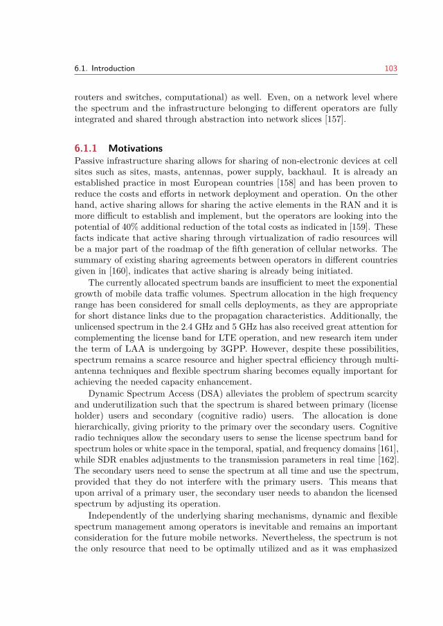
6.1. Introduction 103
routers and switches, computational) as well. Even, on a network level wherethe spectrum and the infrastructure belonging to different operators are fullyintegrated and shared through abstraction into network slices [157].
6.1.1 MotivationsPassive infrastructure sharing allows for sharing of non-electronic devices at cellsites such as sites, masts, antennas, power supply, backhaul. It is already anestablished practice in most European countries [158] and has been proven toreduce the costs and efforts in network deployment and operation. On the otherhand, active sharing allows for sharing the active elements in the RAN and it ismore difficult to establish and implement, but the operators are looking into thepotential of 40% additional reduction of the total costs as indicated in [159]. Thesefacts indicate that active sharing through virtualization of radio resources willbe a major part of the roadmap of the fifth generation of cellular networks. Thesummary of existing sharing agreements between operators in different countriesgiven in [160], indicates that active sharing is already being initiated.
The currently allocated spectrum bands are insufficient to meet the exponentialgrowth of mobile data traffic volumes. Spectrum allocation in the high frequencyrange has been considered for small cells deployments, as they are appropriatefor short distance links due to the propagation characteristics. Additionally, theunlicensed spectrum in the 2.4 GHz and 5 GHz has also received great attention forcomplementing the license band for LTE operation, and new research item underthe term of LAA is undergoing by 3GPP. However, despite these possibilities,spectrum remains a scarce resource and higher spectral efficiency through multi-antenna techniques and flexible spectrum sharing becomes equally important forachieving the needed capacity enhancement.
Dynamic Spectrum Access (DSA) alleviates the problem of spectrum scarcityand underutilization such that the spectrum is shared between primary (licenseholder) users and secondary (cognitive radio) users. The allocation is donehierarchically, giving priority to the primary over the secondary users. Cognitiveradio techniques allow the secondary users to sense the license spectrum band forspectrum holes or white space in the temporal, spatial, and frequency domains [161],while SDR enables adjustments to the transmission parameters in real time [162].The secondary users need to sense the spectrum at all time and use the spectrum,provided that they do not interfere with the primary users. This means thatupon arrival of a primary user, the secondary user needs to abandon the licensedspectrum by adjusting its operation.
Independently of the underlying sharing mechanisms, dynamic and flexiblespectrum management among operators is inevitable and remains an importantconsideration for the future mobile networks. Nevertheless, the spectrum is notthe only resource that need to be optimally utilized and as it was emphasized
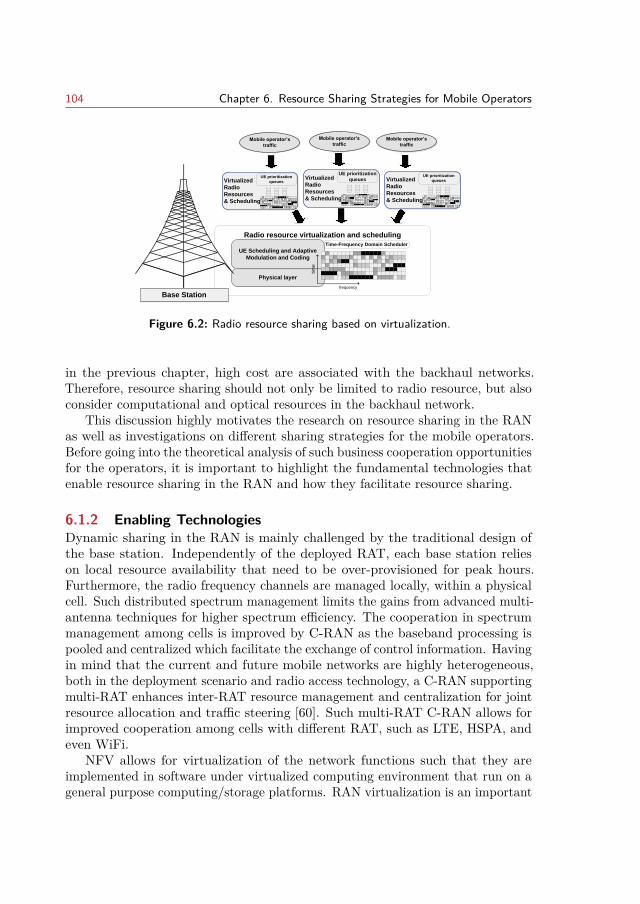
104 Chapter 6. Resource Sharing Strategies for Mobile Operators
Radio resource virtualization and scheduling
Physical layer
UE Scheduling and Adaptive
Modulation and Coding
SiteSite
tim
e
frequency
Time-Frequency Domain Scheduler
Mobile operator’s
traffic
Base Station
Virtualized
Radio
Resources
& Scheduling
UE prioritization
queuesVirtualized
Radio
Resources
& Scheduling
UE prioritization
queues Virtualized
Radio
Resources
& Scheduling
UE prioritization
queues
Mobile operator’s
trafficMobile operator’s
traffic
Figure 6.2: Radio resource sharing based on virtualization.
in the previous chapter, high cost are associated with the backhaul networks.Therefore, resource sharing should not only be limited to radio resource, but alsoconsider computational and optical resources in the backhaul network.
This discussion highly motivates the research on resource sharing in the RANas well as investigations on different sharing strategies for the mobile operators.Before going into the theoretical analysis of such business cooperation opportunitiesfor the operators, it is important to highlight the fundamental technologies thatenable resource sharing in the RAN and how they facilitate resource sharing.
6.1.2 Enabling TechnologiesDynamic sharing in the RAN is mainly challenged by the traditional design ofthe base station. Independently of the deployed RAT, each base station relieson local resource availability that need to be over-provisioned for peak hours.Furthermore, the radio frequency channels are managed locally, within a physicalcell. Such distributed spectrum management limits the gains from advanced multi-antenna techniques for higher spectrum efficiency. The cooperation in spectrummanagement among cells is improved by C-RAN as the baseband processing ispooled and centralized which facilitate the exchange of control information. Havingin mind that the current and future mobile networks are highly heterogeneous,both in the deployment scenario and radio access technology, a C-RAN supportingmulti-RAT enhances inter-RAT resource management and centralization for jointresource allocation and traffic steering [60]. Such multi-RAT C-RAN allows forimproved cooperation among cells with different RAT, such as LTE, HSPA, andeven WiFi.
NFV allows for virtualization of the network functions such that they areimplemented in software under virtualized computing environment that run on ageneral purpose computing/storage platforms. RAN virtualization is an important
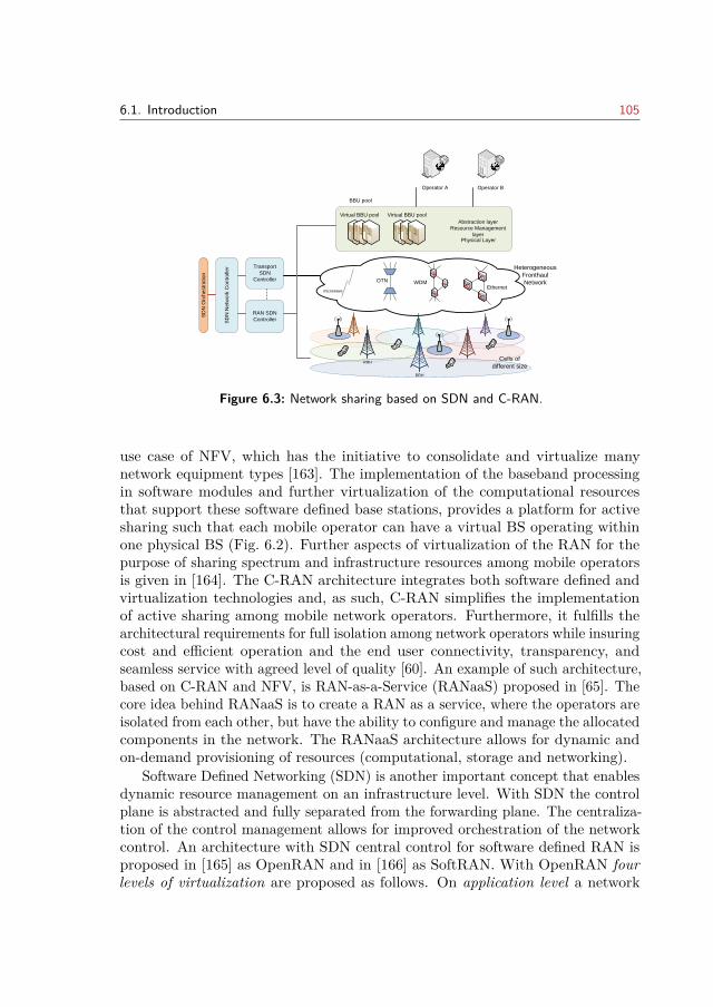
6.1. Introduction 105
RRH
RRH
Heterogeneous
Fronthaul
Network
Multi-RAT RRH
Cells of
different size
BBU pool
Virtual BBU pool
Abstraction layer
Physical Layer
Resource Management
layer
Virtual BBU pool
microwave
OTN WDMEthernet
RAN SDN
Controller
Transport
SDN
Controller
SD
N N
etw
ork
Co
ntr
olle
r
SD
N O
rch
estr
atio
n
Operator A Operator B
Figure 6.3: Network sharing based on SDN and C-RAN.
use case of NFV, which has the initiative to consolidate and virtualize manynetwork equipment types [163]. The implementation of the baseband processingin software modules and further virtualization of the computational resourcesthat support these software defined base stations, provides a platform for activesharing such that each mobile operator can have a virtual BS operating withinone physical BS (Fig. 6.2). Further aspects of virtualization of the RAN for thepurpose of sharing spectrum and infrastructure resources among mobile operatorsis given in [164]. The C-RAN architecture integrates both software defined andvirtualization technologies and, as such, C-RAN simplifies the implementationof active sharing among mobile network operators. Furthermore, it fulfills thearchitectural requirements for full isolation among network operators while insuringcost and efficient operation and the end user connectivity, transparency, andseamless service with agreed level of quality [60]. An example of such architecture,based on C-RAN and NFV, is RAN-as-a-Service (RANaaS) proposed in [65]. Thecore idea behind RANaaS is to create a RAN as a service, where the operators areisolated from each other, but have the ability to configure and manage the allocatedcomponents in the network. The RANaaS architecture allows for dynamic andon-demand provisioning of resources (computational, storage and networking).
Software Defined Networking (SDN) is another important concept that enablesdynamic resource management on an infrastructure level. With SDN the controlplane is abstracted and fully separated from the forwarding plane. The centraliza-tion of the control management allows for improved orchestration of the networkcontrol. An architecture with SDN central control for software defined RAN isproposed in [165] as OpenRAN and in [166] as SoftRAN. With OpenRAN fourlevels of virtualization are proposed as follows. On application level a network
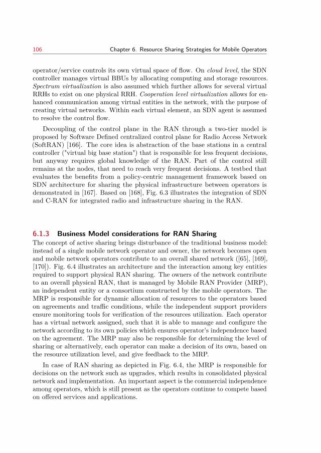
106 Chapter 6. Resource Sharing Strategies for Mobile Operators
operator/service controls its own virtual space of flow. On cloud level, the SDNcontroller manages virtual BBUs by allocating computing and storage resources.Spectrum virtualization is also assumed which further allows for several virtualRRHs to exist on one physical RRH. Cooperation level virtualization allows for en-hanced communication among virtual entities in the network, with the purpose ofcreating virtual networks. Within each virtual element, an SDN agent is assumedto resolve the control flow.
Decoupling of the control plane in the RAN through a two-tier model isproposed by Software Defined centralized control plane for Radio Access Network(SoftRAN) [166]. The core idea is abstraction of the base stations in a centralcontroller ("virtual big base station") that is responsible for less frequent decisions,but anyway requires global knowledge of the RAN. Part of the control stillremains at the nodes, that need to reach very frequent decisions. A testbed thatevaluates the benefits from a policy-centric management framework based onSDN architecture for sharing the physical infrastructure between operators isdemonstrated in [167]. Based on [168], Fig. 6.3 illustrates the integration of SDNand C-RAN for integrated radio and infrastructure sharing in the RAN.
6.1.3 Business Model considerations for RAN SharingThe concept of active sharing brings disturbance of the traditional business model:instead of a single mobile network operator and owner, the network becomes openand mobile network operators contribute to an overall shared network ([65], [169],[170]). Fig. 6.4 illustrates an architecture and the interaction among key entitiesrequired to support physical RAN sharing. The owners of the network contributeto an overall physical RAN, that is managed by Mobile RAN Provider (MRP),an independent entity or a consortium constructed by the mobile operators. TheMRP is responsible for dynamic allocation of resources to the operators basedon agreements and traffic conditions, while the independent support providersensure monitoring tools for verification of the resources utilization. Each operatorhas a virtual network assigned, such that it is able to manage and configure thenetwork according to its own policies which ensures operator’s independence basedon the agreement. The MRP may also be responsible for determining the level ofsharing or alternatively, each operator can make a decision of its own, based onthe resource utilization level, and give feedback to the MRP.
In case of RAN sharing as depicted in Fig. 6.4, the MRP is responsible fordecisions on the network such as upgrades, which results in consolidated physicalnetwork and implementation. An important aspect is the commercial independenceamong operators, which is still present as the operators continue to compete basedon offered services and applications.
6.1. Introduction 107
Mobile Nework Provider (joint venture or neutral broker)
Mobile Operator Mobile Operator Mobile Operator
Physical radio Access Network elements
Network Owners
Network Owners
Mobile Support Provider
Network Owners
Gathering statistics from virtual BSManages consolidated network of base stations
Dynamic and on-demand allocation of resources
Monitoring and resource assignment verification
UE
UEUE
UE
UE
UE
UEUE
UE
UE
UE
UEUE
UE
UE
Network Owners
Figure 6.4: Mobile operator architecture by virtualization
6.1.4 Study Objectives and AssumptionsThe main objective of the study is to investigate dynamic sharing of resourcesin the radio access network, where operators decide to share a certain degree oftheir resources with other operators. This chapter offers a quantitative study onthe overall network performance and characterization of the individual benefitswith the relation of the sharing degree. In the assessment it is assumed fullvirtualization of the resources in a RAN. The allocation units in the spectrum canbe defined as channels in WiFi or PRB in LTE, or even portions of white space.Beside the time/frequency allocation, space, code and power can also be defined.The analysis in this chapter generalizes the resources in the RAN, and they canbe defined as computational resources and/or spectral resources.
Global knowledge of the resource arrangement is assumed, such that theirallocation is seamless and can be rearranged among the requesting entities. Forexample if all the radio resources within one cell are occupied, rearrangementof the calls is possible in order to release the required resources. Such globalintelligence is an important assumption from the theoretical point, and allows tomodel the network as a network with direct routing which was introduced in theprevious chapter.
It is assumed that each operator owns certain percentage of the total resourcesand enters a sharing agreement. The agreement can define the portion of resourcesthat are shared among all operators and can be accessed on a first come firstserved basis. The performance metrics considered in order to evaluate the benefitsfrom sharing are the individual blocking probability and the carried traffic. Theresults from studies indicate the optimal degree of sharing such that the agreedperformance for each operator is not compromised. The model can be appliedfor multiple operators, while in the numerical analysis we focus on two operators
108 Chapter 6. Resource Sharing Strategies for Mobile Operators
where we evaluate the sharing degree under different traffic loads, traffic variationand network dimensioning. We consider the impact of sharing strategies in case ofa resource sharing within one cell and sharing the resources within a geographicalarea covered by a heterogeneous network consisting of cells with different sizes.
6.2 Related Work
Resource sharing among self-centered and competitive operators has been provento be beneficial for all involved entities ([8]-[17]). The degree of benefit is dependenton the type of access to the shared resources that can be based on the principlessuch as first come first served or some other predefined priority models. The sharingcan be regulated according to a utility function, game theory, auctions, etc., wherecapacity, efficiency, energy consumption, price of spectrum, revenue, resourceutilization, and load influence the decision. These principles define the agreementfor sharing resources among the involved entities and depend on many parameterssuch as cost, load, level of quality, etc. The benefits of sharing resources amongoperators via the Cloud RAN has been analyzed in [171]. The paper presents astudy of the resource sharing influence on the network performance, which couldbe useful when making agreement between operators as well as strategic decisionsin network dimensioning.
In [172], the authors investigate a type of sharing where the users connectto the closest BS (form of national roaming), rather than to the home operatorit belongs to. The spectrum is negotiated among the different operators andidealistic centralized scheduler is assumed. The results show that this type ofsharing leads to better performance in terms of total average frame delay. Gametheory approach for spectrum sharing has been considered in [173], [174] and[175]. In the first two paper, a utility function is defined based on the requiredservice rate, spectrum price, and blocking probability according to which the usersdecide on how to share (trade) a common pool of spectral resources. In [175]a detailed microeconomic analysis based on game theory is given such that thegoal of the participants (operators) is to minimize the energy consumption byswitching off BSs and redirecting the traffic to a common BS with shared capacity.The trade off between reaching a global optimum and performance optimizationfor individual operator is considered in [176]. The work in [176] indicates that bydeviating from the sharing guarantee, the overall spectral efficiency is increased.Furthermore, it shows the limitation of the spectral efficiency, meaning that thereis a pivotal point of the deviation, after which no improvement is observed.
In [177] several types of sharing among competitive operators are compared:capacity sharing, spectrum sharing, virtual spectrum sharing, and virtual PRBsharing. The capacity sharing outperforms the other sharing methods and has beenidentified as most appropriate for the traditional network design. Yet, capacity
6.3. Resource sharing at a single cell 109
sharing is a form of national roaming and requires load based traffic steering to beimplemented (involving UE handover). The paper also shows the importance ofvirtualization of the radio resources, as the virtual PRB sharing performs very closeto capacity sharing. As implemented through two tier scheduler (one responsiblefor prioritization of flows within operator, and the second one for scheduling amongUEs), the multiuser diversity is exploited and the spectral efficiency is maximized.
The need for two tier scheduler is also emphasized in [178], [179] and [180].These papers show the advances in sharing resources through slicing of wirelessresources. The first two papers consider a single base station sharing analysis,while the last one concludes that the sharing agreement should be on a largergeographical area as the traffic dynamics varies in time and area. The sharingdecision is based on a minimum reserved resources for each operator, while theremaining resources are shared on a first come first served basis. The sum of allresources that are assigned to the involved entities is larger than the total amountof resources in order to exploit statistical multiplexing.
6.3 Resource sharing at a single cell
In this case study the benefits of resource sharing are investigated. The decisionon the sharing degree is made local, within a single cell area that is served bytwo virtual base stations. The main purpose of the case study is to see how thevariations of the traffic belonging to one operator influence the performance ofthe other, depending on the sharing degree. This study can be used for exampleto grant the MRP to decide on the sharing degree dynamically, by following thetraffic load of the operators.
6.3.1 Analytical modelThe model is based on Fig. 6.2, such that it is assumed that n RAN resources (RR)are available within a cell area. These resources are shared among N individualmobile operators. The subscribers of each operator generate a flow of Binomial,Poisson or Pascal (BPP) traffic, characterized with mean value Ai, peakedness(ratio of variance and mean value) Zi. Each connection requires di resources forthe duration of the connection. The BS operates as a full accessible lost-callscleared system so that a call from operator i is blocked when less than di resourcesare available. Each operator owns ni resources, such that
∑Ni=1 ni = n. The
operators are encouraged to enter a sharing agreement in order to increase theindividual and overall performance. The operators decide to share a certain degrees ∈ [0, 1] of the resources. Then operator i has ((1− s) · ni) resources reserved,but can use at most nsi = (ni + s · (n − ni)) resources. This problem can bedescribed by a N dimensional Markovian process with state space (x1, x2, ..., xN )where xi = ci · di and ci represent the number of connections for operator i. The
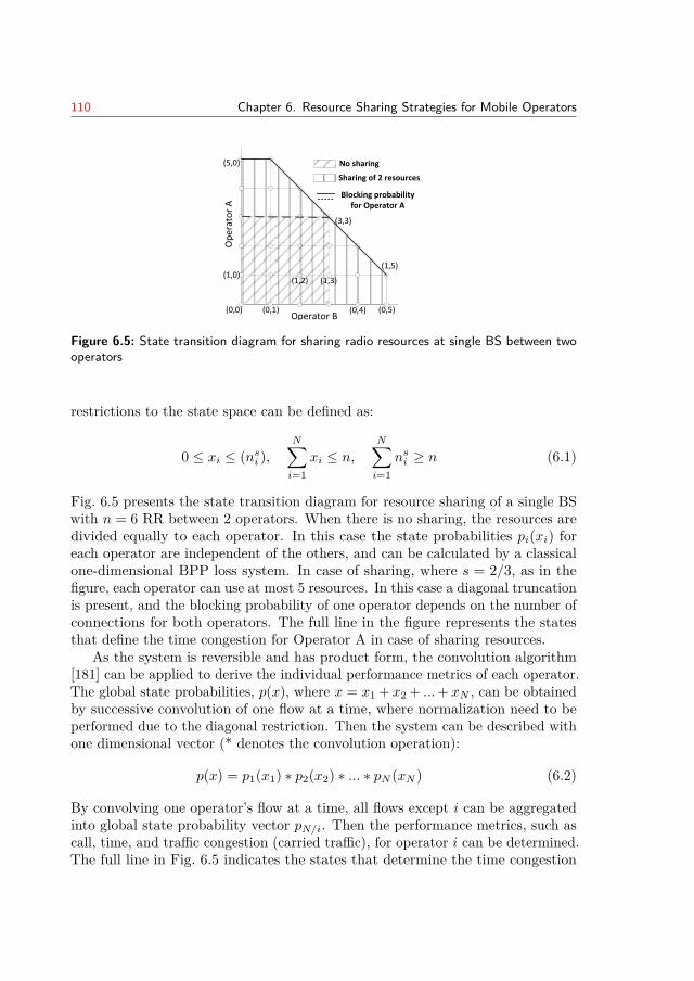
110 Chapter 6. Resource Sharing Strategies for Mobile Operators
No sharing
Sharing of 2 resources
Blocking probabilityfor Operator A
Op
erat
or
A
Operator B(0,0) (0,1)
(1,2) (1,3)
(0,4) (0,5)
(3,3)
(1,5)(1,0)
(5,0)
Figure 6.5: State transition diagram for sharing radio resources at single BS between twooperators
restrictions to the state space can be defined as:
0 ≤ xi ≤ (nsi ),N∑i=1
xi ≤ n,N∑i=1
nsi ≥ n (6.1)
Fig. 6.5 presents the state transition diagram for resource sharing of a single BSwith n = 6 RR between 2 operators. When there is no sharing, the resources aredivided equally to each operator. In this case the state probabilities pi(xi) foreach operator are independent of the others, and can be calculated by a classicalone-dimensional BPP loss system. In case of sharing, where s = 2/3, as in thefigure, each operator can use at most 5 resources. In this case a diagonal truncationis present, and the blocking probability of one operator depends on the number ofconnections for both operators. The full line in the figure represents the statesthat define the time congestion for Operator A in case of sharing resources.
As the system is reversible and has product form, the convolution algorithm[181] can be applied to derive the individual performance metrics of each operator.The global state probabilities, p(x), where x = x1 + x2 + ...+ xN , can be obtainedby successive convolution of one flow at a time, where normalization need to beperformed due to the diagonal restriction. Then the system can be described withone dimensional vector (* denotes the convolution operation):
p(x) = p1(x1) ∗ p2(x2) ∗ ... ∗ pN (xN ) (6.2)
By convolving one operator’s flow at a time, all flows except i can be aggregatedinto global state probability vector pN/i. Then the performance metrics, such ascall, time, and traffic congestion (carried traffic), for operator i can be determined.The full line in Fig. 6.5 indicates the states that determine the time congestion
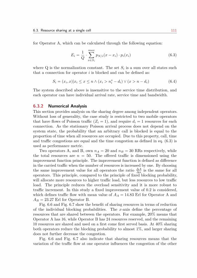
6.3. Resource sharing at a single cell 111
for Operator A, which can be calculated through the following equation:
Ei = 1Q·max∑x∈Si
pN/i(x− xi) · pi(xi) (6.3)
where Q is the normalization constant. The set Si is a sum over all states suchthat a connection for operator i is blocked and can be defined as:
Si = (xi, x)|xi ≤ x ≤ n ∧ (xi > nsi − di) ∨ (x > n− di) (6.4)
The system described above is insensitive to the service time distribution, andeach operator can have individual arrival rate, service time and bandwidth.
6.3.2 Numerical AnalysisThis section provides analysis on the sharing degree among independent operators.Without loss of generality, the case study is restricted to two mobile operatorsthat have flows of Poisson traffic (Zi = 1), and require di = 1 resources for eachconnection. As the stationary Poisson arrival process does not depend on thesystem state, the probability that an arbitrary call is blocked is equal to theproportion of time when all resources are occupied. Due to this property, call, timeand traffic congestions are equal and the time congestion as defined in eq. (6.3) isused as performance metric.
Two operators A, and B, own nA = 20 and nB = 30 RRs respectively, whilethe total resources are n = 50. The offered traffic is dimensioned using theimprovement function principle. The improvement function is defined as differencein the carried traffic when the number of resources is increased by one. By choosingthe same improvement value for all operators the ratio ∆A
∆n is the same for alloperators. This principle, compared to the principle of fixed blocking probability,will allocate more resources to higher traffic load, but less resources to low trafficload. The principle reduces the overload sensitivity and it is more robust totraffic increment. In this study a fixed improvement value of 0.2 is considered,which defines traffic flow with mean value of AA = 14.83 Erl for Operator A andAB = 23.27 Erl for Operator B.
Fig. 6.6 and Fig. 6.7 show the benefit of sharing resources in terms of reductionof the individual blocking probabilities. The x-axis define the percentage ofresources that are shared between the operators. For example, 20% means thatOperator A has 16, while Operator B has 24 resources reserved, and the remaining10 resources are shared and used on a first come first served basis. At 40% sharingboth operators reduce the blocking probability to almost 1%, and larger sharingdoes not further decrease the congestion.
Fig. 6.6 and Fig. 6.7 also indicate that sharing resources means that thevariation of the traffic flow at one operator influences the congestion of the other
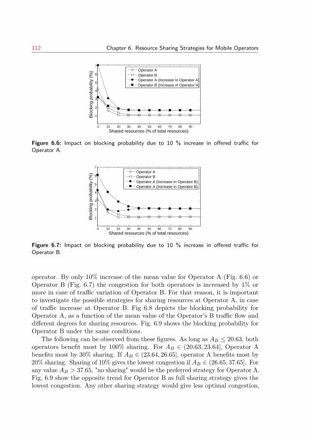
112 Chapter 6. Resource Sharing Strategies for Mobile Operators
0 10 20 30 40 50 60 70 80 90
1
2
3
4
5
6
7
Shared resources (% of total resources)
Blo
ckin
g pr
obab
ility
(%
)
N 50 N1 20 N2 30 A1 14.830 A2 23.270 F1 0.200 F2 0.200 I 10
Operator AOperator BOperator A (Increase in Operator A)Operator B (Increase in Operator A)
Figure 6.6: Impact on blocking probability due to 10 % increase in offered traffic forOperator A.
0 10 20 30 40 50 60 70 80 90
1
2
3
4
5
6
7
Shared resources (% of total resources)
Blo
ckin
g pr
obab
ility
(%
)
Operator AOperator BOperator A (Increase in Operator B)Operator A (Increase in Operator B)
Figure 6.7: Impact on blocking probability due to 10 % increase in offered traffic forOperator B.
operator. By only 10% increase of the mean value for Operator A (Fig. 6.6) orOperator B (Fig. 6.7) the congestion for both operators is increased by 1% ormore in case of traffic variation of Operator B. For that reason, it is importantto investigate the possible strategies for sharing resources at Operator A, in caseof traffic increase at Operator B. Fig 6.8 depicts the blocking probability forOperator A, as a function of the mean value of the Operator’s B traffic flow anddifferent degrees for sharing resources. Fig. 6.9 shows the blocking probability forOperator B under the same conditions.
The following can be observed from these figures. As long as AB ≤ 20.63, bothoperators benefit most by 100% sharing. For AB ∈ (20.63, 23.64], Operator Abenefits most by 30% sharing. If AB ∈ (23.64, 26.65], operator A benefits most by20% sharing. Sharing of 10% gives the lowest congestion if AB ∈ (26.65, 37.65]. Forany value AB > 37.65, "no sharing" would be the preferred strategy for Operator A.Fig. 6.9 show the opposite trend for Operator B as full sharing strategy gives thelowest congestion. Any other sharing strategy would give less optimal congestion,
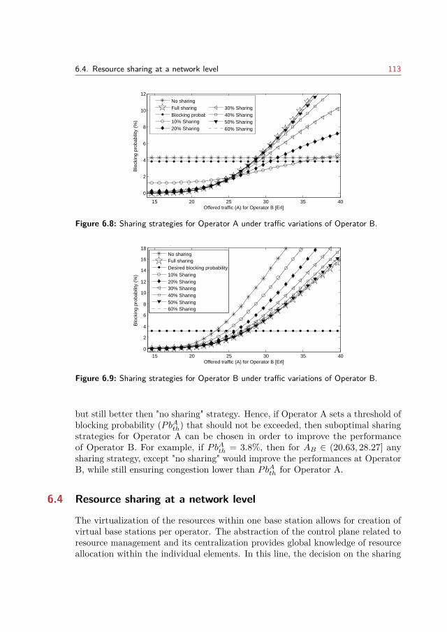
6.4. Resource sharing at a network level 113
15 20 25 30 35 40
0
2
4
6
8
10
12
Offered traffic (A) for Operator B [Erl]
Blo
ckin
g pr
obab
ility
(%
)
Blocking Prob Service1 N 50 N1 20 N2 30 A1 14.830 A2 23.270 F1 0.200 F2 0.200
No sharingFull sharingBlocking probability threshold10% Sharing20% Sharing
30% Sharing40% Sharing50% Sharing60% Sharing
Figure 6.8: Sharing strategies for Operator A under traffic variations of Operator B.
15 20 25 30 35 400
2
4
6
8
10
12
14
16
18
Offered traffic (A) for Operator B [Erl]
Blo
ckin
g pr
obab
ility
(%
)
Blocking Prob Service2 N 50 N1 20 N2 30 A1 14.830 A2 23.270 F1 0.200 F2 0.200
No sharingFull sharingDesired blocking probability10% Sharing20% Sharing30% Sharing40% Sharing50% Sharing60% Sharing
Figure 6.9: Sharing strategies for Operator B under traffic variations of Operator B.
but still better then "no sharing" strategy. Hence, if Operator A sets a threshold ofblocking probability (PbAth) that should not be exceeded, then suboptimal sharingstrategies for Operator A can be chosen in order to improve the performanceof Operator B. For example, if PbAth = 3.8%, then for AB ∈ (20.63, 28.27] anysharing strategy, except "no sharing" would improve the performances at OperatorB, while still ensuring congestion lower than PbAth for Operator A.
6.4 Resource sharing at a network level
The virtualization of the resources within one base station allows for creation ofvirtual base stations per operator. The abstraction of the control plane related toresource management and its centralization provides global knowledge of resourceallocation within the individual elements. In this line, the decision on the sharing
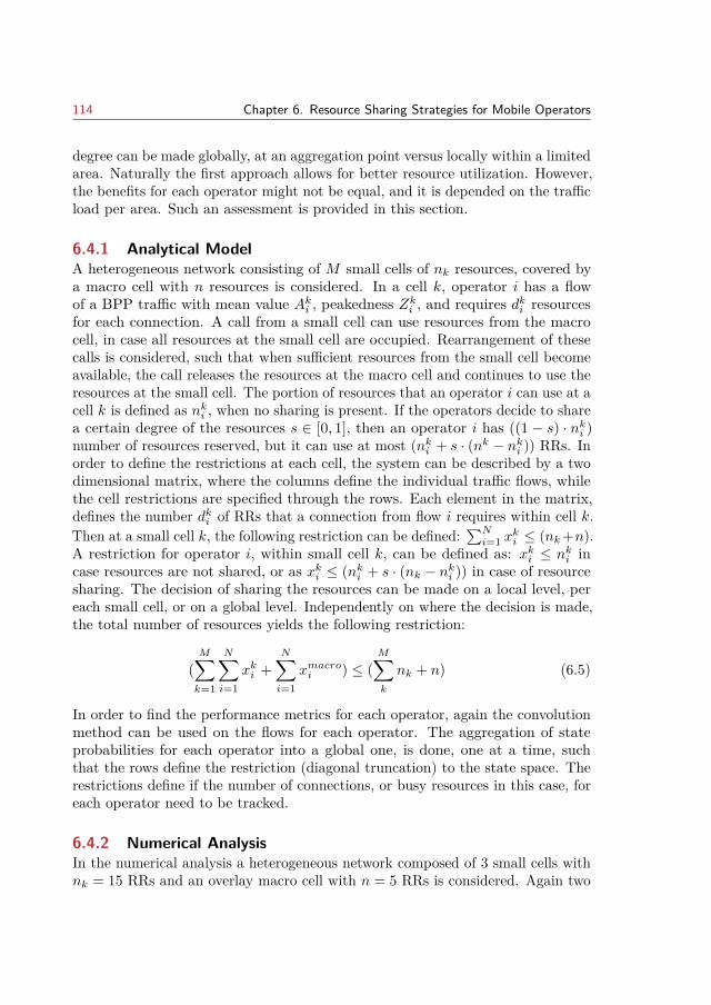
114 Chapter 6. Resource Sharing Strategies for Mobile Operators
degree can be made globally, at an aggregation point versus locally within a limitedarea. Naturally the first approach allows for better resource utilization. However,the benefits for each operator might not be equal, and it is depended on the trafficload per area. Such an assessment is provided in this section.
6.4.1 Analytical ModelA heterogeneous network consisting of M small cells of nk resources, covered bya macro cell with n resources is considered. In a cell k, operator i has a flowof a BPP traffic with mean value Aki , peakedness Zki , and requires dki resourcesfor each connection. A call from a small cell can use resources from the macrocell, in case all resources at the small cell are occupied. Rearrangement of thesecalls is considered, such that when sufficient resources from the small cell becomeavailable, the call releases the resources at the macro cell and continues to use theresources at the small cell. The portion of resources that an operator i can use at acell k is defined as nki , when no sharing is present. If the operators decide to sharea certain degree of the resources s ∈ [0, 1], then an operator i has ((1 − s) · nki )number of resources reserved, but it can use at most (nki + s · (nk − nki )) RRs. Inorder to define the restrictions at each cell, the system can be described by a twodimensional matrix, where the columns define the individual traffic flows, whilethe cell restrictions are specified through the rows. Each element in the matrix,defines the number dki of RRs that a connection from flow i requires within cell k.Then at a small cell k, the following restriction can be defined:
∑Ni=1 x
ki ≤ (nk+n).
A restriction for operator i, within small cell k, can be defined as: xki ≤ nki incase resources are not shared, or as xki ≤ (nki + s · (nk − nki )) in case of resourcesharing. The decision of sharing the resources can be made on a local level, pereach small cell, or on a global level. Independently on where the decision is made,the total number of resources yields the following restriction:
(M∑k=1
N∑i=1
xki +N∑i=1
xmacroi ) ≤ (M∑k
nk + n) (6.5)
In order to find the performance metrics for each operator, again the convolutionmethod can be used on the flows for each operator. The aggregation of stateprobabilities for each operator into a global one, is done, one at a time, suchthat the rows define the restriction (diagonal truncation) to the state space. Therestrictions define if the number of connections, or busy resources in this case, foreach operator need to be tracked.
6.4.2 Numerical AnalysisIn the numerical analysis a heterogeneous network composed of 3 small cells withnk = 15 RRs and an overlay macro cell with n = 5 RRs is considered. Again two
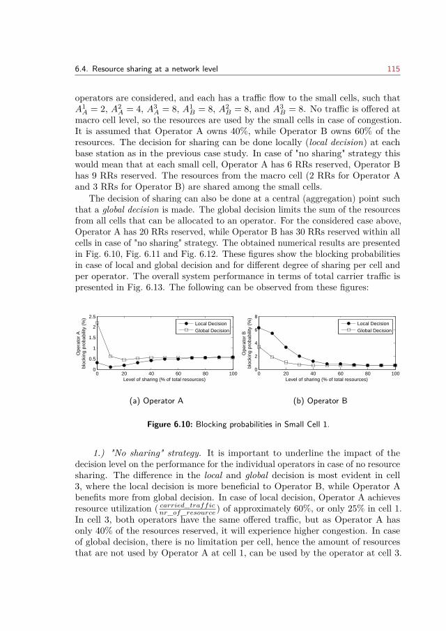
6.4. Resource sharing at a network level 115
operators are considered, and each has a traffic flow to the small cells, such thatA1A = 2, A2
A = 4, A3A = 8, A1
B = 8, A2B = 8, and A3
B = 8. No traffic is offered atmacro cell level, so the resources are used by the small cells in case of congestion.It is assumed that Operator A owns 40%, while Operator B owns 60% of theresources. The decision for sharing can be done locally (local decision) at eachbase station as in the previous case study. In case of "no sharing" strategy thiswould mean that at each small cell, Operator A has 6 RRs reserved, Operator Bhas 9 RRs reserved. The resources from the macro cell (2 RRs for Operator Aand 3 RRs for Operator B) are shared among the small cells.
The decision of sharing can also be done at a central (aggregation) point suchthat a global decision is made. The global decision limits the sum of the resourcesfrom all cells that can be allocated to an operator. For the considered case above,Operator A has 20 RRs reserved, while Operator B has 30 RRs reserved within allcells in case of "no sharing" strategy. The obtained numerical results are presentedin Fig. 6.10, Fig. 6.11 and Fig. 6.12. These figures show the blocking probabilitiesin case of local and global decision and for different degree of sharing per cell andper operator. The overall system performance in terms of total carrier traffic ispresented in Fig. 6.13. The following can be observed from these figures:
0 20 40 60 80 1000
0.5
1
1.5
2
2.5
Level of sharing (% of total resources)
Ope
rato
r A
bloc
king
pro
babi
lity
(%)
Local DecisionGlobal Decision
(a) Operator A
0 20 40 60 80 1000
2
4
6
8
Level of sharing (% of total resources)
Ope
rato
r B
bloc
king
pro
babi
lity
(%)
Local DecisionGlobal Decision
(b) Operator B
Figure 6.10: Blocking probabilities in Small Cell 1.
1.) "No sharing" strategy. It is important to underline the impact of thedecision level on the performance for the individual operators in case of no resourcesharing. The difference in the local and global decision is most evident in cell3, where the local decision is more beneficial to Operator B, while Operator Abenefits more from global decision. In case of local decision, Operator A achievesresource utilization ( carried_traffic
nr_of_resource ) of approximately 60%, or only 25% in cell 1.In cell 3, both operators have the same offered traffic, but as Operator A hasonly 40% of the resources reserved, it will experience higher congestion. In caseof global decision, there is no limitation per cell, hence the amount of resourcesthat are not used by Operator A at cell 1, can be used by the operator at cell 3.
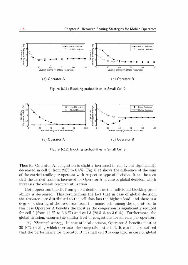
116 Chapter 6. Resource Sharing Strategies for Mobile Operators
0 20 40 60 80 1000
1
2
3
4
Level of sharing (% of total resources)
Ope
rato
r A
bloc
king
pro
babi
lity
(%)
Local DecisionGlobal Decision
(a) Operator A
0 20 40 60 80 1000
2
4
6
8
Level of sharing (% of total resources)
Ope
rato
r B
bloc
king
pro
babi
lity
(%)
Local DecisionGlobal Decision
(b) Operator B
Figure 6.11: Blocking probabilities in Small Cell 2.
0 20 40 60 80 1005
10
15
20
25
Level of sharing (% of total resources)
Ope
rato
r A
bloc
king
pro
babi
lity
(%)
Local DecisionGlobal Decision
(a) Operator A
0 20 40 60 80 1005
6
7
8
9
Level of sharing (% of total resources)
Ope
rato
r B
bloc
king
pro
babi
lity
(%)
Local DecisionGlobal Decision
(b) Operator B
Figure 6.12: Blocking probabilities in Small Cell 3.
Thus for Operator A, congestion is slightly increased in cell 1, but significantlydecreased in cell 3, from 24% to 6.5%. Fig. 6.13 shows the difference of the sumof the carried traffic per operator with respect to type of decision. It can be seenthat the carried traffic is increased for Operator A in case of global decision, whichincreases the overall resource utilization.
Both operators benefit from global decision, as the individual blocking prob-ability is decreased. This results from the fact that in case of global decision,the resources are distributed to the cell that has the highest load, and there is adegree of sharing of the resources from the macro cell among the operators. Inthis case Operator A benefits the most as the congestion is significantly reducedfor cell 2 (from 11 % to 3.6 %) and cell 3 (28.5 % to 3.6 %). Furthermore, theglobal decision, ensures the similar level of congestions for all cells per operator.
2.) "Sharing" strategy. In case of local decision, Operator A benefits most at30-40% sharing which decreases the congestion at cell 3. It can be also noticedthat the performance for Operator B in small cell 3 is degraded in case of global
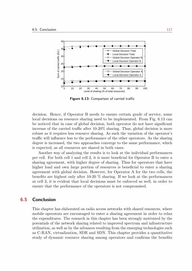
6.5. Conclusion 117
0 10 20 30 40 50 60 70 80 90 10010
15
20
25
30
35
40
Level of sharing (% of total resources)
Sum
of c
arrie
d tr
affic
(E
rl.)
Global Decision TotalLocal Decision TotalGlobal Decision Operator BLocal Decision Operator B
Global Decision Operator ALocal Decision Operator A
Figure 6.13: Comparison of carried traffic
decision. Hence, if Operator B needs to ensure certain grade of service, somelocal decisions on resource sharing need to be implemented. From Fig. 6.13 canbe noticed that in case of global decision, both operator do not have significantincrease of the carried traffic after 10-20% sharing. Thus, global decision is morerobust as it requires less resource sharing. As such the variation of the operator’straffic will influence less to the performance of the other operators. As the sharingdegree is increased, the two approaches converge to the same performance, whichis expected, as all resources are shared in both cases.
Another way of analyzing the results is to look at the individual performancesper cell. For both cell 1 and cell 2, it is more beneficial for Operator B to enter asharing agreement, with higher degree of sharing. Thus for operators that havehigher load and own large portion of resources is beneficial to enter a sharingagreement with global decision. However, for Operator A for the two cells, thebenefits are highest only after 10-20 % sharing. If we look at the performancesat cell 3, it is evident that local decisions must be enforced as well, in order toensure that the performance of the operators is not compromised.
6.5 Conclusion
This chapter has elaborated on radio access networks with shared resources, wheremobile operators are encouraged to enter a sharing agreement in order to relaxthe expenditures. The research in this chapter has been strongly motivated by thepotentials of the network sharing related to improved spectrum and infrastructureutilization, as well as by the advances resulting from the emerging technologies suchas C-RAN, virtualization, SDR and SDN. This chapter provides a quantitativestudy of dynamic resource sharing among operators and confirms the benefits
118 Chapter 6. Resource Sharing Strategies for Mobile Operators
seen from overall network utilization. More importantly, the numerical analysisprovided gives insights on the performances of the individual operators, whichreveals that the benefits are unequal for operators and dependent on severalparameters.
In the analysis two operators and a shared pool of resources is considered.The operators contribute to the shared pool of resources by deciding on a sharingpercent from its own resource pool. The sharing decision strategies have beenanalyzed at a local level at a single cell, as well as on a global level that relates toan aggregation point in a heterogeneous network. Although the numerical analysisis given for two operators, the analytical method proposed is general and it canbe applied to larger number of operators and various scenarios such as in case ofmulti-RAT deployments.
The results from the study clearly show that by increasing the level of sharing,the two operators can benefit by having a decreased blocking probability, both forlocal and global decision. The novelty in this work is the analysis of the influenceof traffic variation for Operator A, on the performance to Operator B for differentlevel of sharing. This way a sensitivity study is performed, in order to quantifythe derivative of the congestion for operator A with respect to the variation ofthe offered traffic of Operator B. The results can be used by the RAN providerto dimension the level of sharing in a way to maximize the overall performancewithout compromising the individual performances of each operator. Additionally,the study implies limitation of the allowed traffic per operator in order to optimizethe congestion per operator.
Sharing of the resources in the RAN requires clear bilateral agreements amongoperators that will be supported and approved by the regulators, and strictorchestration that will preserve and enforce the agreements. In this work, theagreement has been considered as a sharing percent, and two cases of enforcementhave been considered: locally within a cell area and globally at an aggregationpoint in a network composed of macro and small cells. It was demonstrated thatthe later one provides better resource utilization in the network, and by only 20% sharing, the total blocking probability is reduced to the case of a system withfull accessibility (100% share). This means that such system is less sensitive totraffic variations. However, a careful analysis per cell reveals that local decisionsneed to be made in order to ensure fair benefits to both operators.
CHAPTER 7Thesis summary
This PhD thesis elaborates on the essentials for contemporary successful resourcemanagement and various performance improvements in heterogeneous networks.The presented novelties provide a comprehensive overviews and discussions of themain issues that need to be considered for better resource utilization, customersatisfaction and fair share for different providers within a heterogeneous network.Analytical approach and used models allows for generalization such that variouscase studies can be studied. The performances of the schemes have been assessedwith system level simulations and/or analytical methods and comparisons withthe previous case studies have been evaluated. The obtained numerical resultsshow expected improvements which lead to valuable recommendation to the actorsin the planning activities.
Chapter 2 presented a novel universal approach for joint resource managementthat facilitates the emerging technologies for spectrum, energy and cost efficiency.The proposed framework is generic and can be applied for various scenarios andnetwork deployments. The different functionalities related to resource managementin a multi-RAT network, (dense) small cell deployments and BS architectureshave been addressed as well. The proposed hierarchical approach provides balancebetween centralized management characterized with global knowledge but excessivesignaling and distributed management with local control of resources. Mostimportantly the individual modules are enhanced with cognitive behavior andlearning abilities in order to assist the decision process and timely adapt tothe changes in the network. The cognitive concept and the SON principlesaugment the proposed framework allowing for more efficient and automatedresource management.
The third chapter dealt with the dual connectivity – a very important newform of multi-cell cooperation for further densification and spectrum extensionthrough exploration of higher spectrum frequencies for the small cells. Bearersplit as a part of dual connectivity, extends carrier aggregation for small cells,allowing for resource aggregation across carries without the need of ideal backhaulconnection. The work presented considered the problem of user power allocationscheme for dual connectivity with bearer split. It proposed that two separateconfigurations per component carrier are maintained: one for single transmissionand the other in case of dual transmissions within a TTI. The design on the powercontrol has been simplified as to ensure minimal coordination among base stations
119
120 Chapter 7. Thesis summary
as well as minimal air interface signaling. An important outcome of this study isthat with bearer split high gains can be achieved for the median and cell edge userthroughput. For cell edge user throughput almost threefold gain is accomplishedfor low load, while approximately 30% gain is achieved at high load (comparedto the case when DC is not configured). The results have indicated that thedistribution of the power is important in order to reduce the possible interferenceincrease in the aggregation layer. However, a deeper study through investigationson the implications on higher layers and other mechanism is also required.
The Chapter 4 has discussed the problem of adaptive traffic allocation incooperative and heterogeneous network. A novel optimization problem has beenproposed with the objective of improving the traffic transmission quality underQoS constraints for different services. Compared to the previous research, thework presented considered three levels of heterogeneity among the available accessnetworks: capacity, delay variations and QoS provisioning. Furthermore, serviceswith different quality requirements have been considered. The numerical resultsfor different case studies confirmed the benefits of multi-stream aggregationover heterogeneous networks. The performance and superiority of the proposedallocation is demonstrated by assessment with traditional allocation methodsknown in the literature. The performance is evaluated with respect to the achievedthroughput, maximum transmission delay among the available interfaces as wellas the buffering requirements needed to reduce the packet reordering at thereceiver. The proposed solution provides flexibility and can be applied for differentdeployments.
The Chapter 5 has focused on C-RAN as an important architecture thatoffers cost benefits and improved radio resource utilization. As energy andcost savings are related to multiplexing gain, this chapter evaluated such gainsunder different network deployments and traffic profiles. The work concludedthe optimal conditions for dense cell deployments under which the multiplexinggain is maximized. The numerical analysis indicated that not only cost, but alsosensitivity to traffic variations need to be investigated when dimensioning the poolof baseband units as the pool size is increased. Highest multiplexing gains oncomputational resources can be achieved in case of full baseband centralization.However, such architecture requires the highest fronthaul capacity and may onlybe viable for operators that can have access to such network at a reasonable cost.Deployments with heterogeneous functional splits have been evaluated in order togive indications on how much of the traffic can be carried on specific interface. Thenumerical results suggested that heterogeneous deployments should be consideredin order to optimally balance the multiplexing gains, spectral efficiency and costof the fronthaul infrastructure.
The last but not least Chapter 6 of this work has paid attention on radioaccess networks with shared resources where mobile operators are encouragedto enter a sharing agreement in order to relax the expenditures. This chapter
7.1. Future Research Directions 121
also investigates strategies for active sharing of the radio access among multipleoperators and has analyzed the individual benefits depending on the sharingdegree. The results from the study clearly showed that by increasing the level ofsharing, the two operators can benefit by having a decreased blocking probability,both for local and global decision. The novelty in this work is the analysis of theinfluence of traffic variation for Operator A on the performance to Operator Bfor different level of sharing. This way a sensitivity study has been performed inorder to quantify the derivative of the congestion for Operator A with respect tothe variation of the offered traffic of Operator B. The results can be used by theRAN provider to dimension the level of sharing in a way to maximize the overallperformance without compromising the individual performances of each operator.Additionally, the study implies limitation of the allowed traffic per operator inorder to optimize the congestion per operator.
7.1 Future Research Directions
The work performed during the Ph.D. study considered different challenges arisingfrom heterogeneity in the mobile networks. The findings in this thesis providemeans for a converged wireless communication that will enhance the seamless userexperience of mobile broadband communications. This is of high importance forthe future Fifth Generation (5G) of mobile communication.
In the future, it is expected even more diversity in mobile networks anddiversity in mobile devices and service requirements resulting from new businessopportunities. Enhancements of the existing mobile communication system willbe developed in order to address the need for higher network capacity and enrichthe mobile broadband experience. In this context, there is a need for furtherexploration in the millimeter wave bands to augment the communication capacity.There is enormous potential in utilizing mmWave for small cell access and for thewireless fronthaul. There are still relevant open issues that need to be addressedin order to facilitate deployments of mmWave in future networks [182].
A novel proposal for a new mobile access medium includes the visible lightbands. The Visible Light Communications (VLC) also called LiFi, enables datatransmission on the intensity of lightning source. This new technology creates anadditional tier in HetNets formed by the LiFi-enabled lights that will be used tooffload the traffic from the other tiers and WiFi hotspots. In this context, [183]indicated the importance of coexistence of WiFi and LiFi, and demonstrated aframework for close integration of these technologies. Their results show that bothtechnologies together can do more than triple the throughput for individual users.
The network society will be further expanded through new use cases beingcreated by various vertical industries, such as public safety, e-health etc. In thiscontext, an important area of future study is the Machine Type Communication
122 Chapter 7. Thesis summary
(MTC). The number of machine devices that are expected to be network connectedwill outline the number of human centric communication devices. But handlingmassive number of devices is not the only challenge - the specific applications thatthese devices have will result in diverse amount of data that need to be transmitted,as well as can have different requirements for cost, power consumption and coverage.
Bibliography[1] A. Checko1st, A. P. Avramova1st, M. Berger, and H. L. Christiansen.
“Evaluating C-RAN fronthaul functional splits in terms of network levelenergy and cost savings”. In: Journal of Communications and Networks(2016). accepted for publication (cit. on pp. xi, 73).
[2] A. P. Avramova, H. Wang, L. Dittmann, and K. I. Pedersen. “ OptimalUplink Power Control for Dual Connected Users in LTE HeterogeneousNetworks”. In: IEEE 83rd Vehicular Technology Conference: VTC2016-Spring. accepted for publication. May 2016 (cit. on pp. xi, 33).
[3] A. P. Avramova and V. Iversen. “Optimal Traffic Allocation for Multi-Stream Aggregation in Heterogeneous Networks”. In: IEEE 7th Int. Work-shop on Heterogeneous and Small Cell Networks (HetSNets), IEEE GLOBE-COM 2015. Dec. 2015 (cit. on pp. xi, 57).
[4] A. P. Avramova, H. L. Christiansen, and V. Iversen. “Cell DeploymentOptimization for Cloud Radio Access Networks using Teletraffic Theory”.In: The 11th Advanced International Conference on Telecommunications,AICT 2015. July 2015 (cit. on pp. xi, 73, 83).
[5] A. P. Avramova and V. Iversen. “Radio Access Sharing Strategies forMultiple Operators in Cellular Networks”. In: The First IEEE InternationalWorkshop on 5G & Beyond - Enabling Technologies and Application, IEEEICC 2015. June 2015, pp. 1113–1118 (cit. on pp. xi, 101).
[6] A. Zakrzewska, A. P. Avramova, H. Christiansen, Y. Yan, A. Checko,A. Dogadaev, S. Ruepp, M. Berger, and L. Dittmann. “A Framework forJoint Optical-Wireless Resource Management in Multi-RAT, HeterogeneousMobile Networks”. In: Workshop on Optical-Wireless Integrated Technologyfor Systems and Networks (OWITSN) 2013, IEEE ICC 2013. June 2013,pp. 895–899 (cit. on pp. xii, 17).
[7] A. Zakrzewska, A. P. Avramova, S. Ruepp, M. Berger, and L. Dittmann.“CSMA-based SON Mechanism for Greening Heterogeneous Networks”. In:INFOCOM Student Session, INFOCOM 2013. Apr. 2013 (cit. on pp. xii,17).
123
124 Bibliography
[8] E. Kisielius, A. Zakrzewska, A. P. Avramova, and S. Ruepp. “EnergyEfficiency in Self Organising Networks”. In: OPNETWORK 2013. Aug.2012 (cit. on pp. xii, 17).
[9] A. P. Avramova, Y. Yan, and L. Dittmann. “Evaluation of a Cross LayerScheduling Algorithm for LTE Downlink.” In: Telfor Journal 5.1 (2013),pp. 26–31 (cit. on p. xii).
[10] A. P. Avramova, Y. Yan, S. Ruepp, and L. Dittmann. “Resource Allocation:Current Issues and Future Directions”. In: 4th Nordic Workshop On SystemAnd Network Optimization For Wireless (SNOW 2013). Apr. 2013 (cit. onp. xii).
[11] A. Dogadaev, A. Checko, A. P. Avramova, A. Zakrzewska, Y. Yan, S. Ruepp,M. Berger, L. Dittmann, and H. Christiansen. “Trafic Steering Frameworkfor Mobile-Assisted Resource Management in Heterogeneous Networks”. In:Ninth International Conference on Wireless and Mobile Communications,ICWMC. July 2013 (cit. on p. xii).
[12] A. P. Avramova, Y. Yan, and L. Dittmann. “Cross layer scheduling algo-rithm for LTE downlink”. In: 20th Telecommunications Forum (TELFOR),2012. Nov. 2012, pp. 307–310 (cit. on p. xii).
[13] A. P. Avramova, Y. Yan, and L. Dittmann. “Modeling and Simulation ofDownlink Subcarrier Allocation Schemes in LTE”. In: OPNETWORK 2012.Aug. 2012 (cit. on p. xii).
[14] A. P. Avramova, Y. Yan, and L. Dittmann. “Modeling of Bandwidth Aggre-gation over Heterogeneous Wireless Access Networks”. In: OPNETWORK2012. Aug. 2012 (cit. on pp. xii, 17).
[15] B. Stojkoska and A. P. Avramova. “Wireless Sensor Networks Frameworkfor Indoor Temperature Regulation”. In: 8th Annual South-East EuropeanDoctoral Student Conference. Sept. 2013, pp. 354–364 (cit. on p. xiii).
[16] B. Stojkoska, A. P. Avramova, and P. Chatzimisios. “Application of WirelessSensor Networks for Indoor Temperature Regulation”. In: InternationalJournal of Distributed Sensor Networks (2014). Article ID 502419 (cit. onp. xiii).
[17] S. Michail, A. P. Avramova, and L. Dittmann. “MIH Based Mobility forTETRA-LTE Network”. In: ICT Innovations 2013. Sept. 2013 (cit. onp. xiii).
[18] A. P. Avramova, S. Ruepp, and L. Dittmann. “Towards Future Broad-band Public Safety Systems: Current Issues and Future Directions”. In:International Conference on Information and Communication TechnologyConvergence (ICTC). Oct. 2015, pp. 74–79 (cit. on p. xiii).
Bibliography 125
[19] Global Mobile Data Traffic Forecast Update, 2015–2020. Tech. rep. CiscoVisual Networking Index, 2016 (cit. on pp. 1, 74).
[20] 3GPP Technical Report (TR) 22.912. Technical Specification Group Servicesand System Aspects; Study into network selection requirements for non-3GPP Access (Release 10). Tech. rep. 3rd Generation Partnership Project(3GPP), March 2011, available at www.3gpp.org (cit. on p. 3).
[21] 3GPP Technical Report (TR) 22.934. Technical Specification Group Servicesand System Aspects; 3GPP system to Wireless Local Area Network (WLAN)interworking; System description (Release 10). Tech. rep. 3rd GenerationPartnership Project (3GPP), March 2011, available at www.3gpp.org (cit.on p. 3).
[22] R. Ferrus, O. Sallent, and R. Agusti. “Interworking in heterogeneous wirelessnetworks: Comprehensive framework and future trends”. In: IEEE WirelessCommunications 17.2 (Apr. 2010), pp. 22–31 (cit. on p. 3).
[23] S. Velentzas and T. Dagiuklas. “4G Cellular/WLAN Interworking”. In:Third International Working Conference HET-NETs 2005. July 2005 (cit.on p. 3).
[24] C. Makaya and S. Pierre. “An Interworking Architecture for HeterogeneousIP Wireless Networks”. In: Wireless and Mobile Communications, 2007.ICWMC ’07. Third International Conference on. Mar. 2007, pp. 16–16(cit. on p. 3).
[25] R. Beaubrun. “Heterogeneous Wireless Access Networks: Architecturesand Protocols”. In: ed. by E. Hossain. Boston, MA: Springer US, 2009.Chap. Integration of Heterogeneous Wireless Access Networks, pp. 1–18(cit. on p. 3).
[26] E. W. C. Perkins. IP Mobility Support for IPv4. RFC 5944. Nov. 2010(cit. on p. 3).
[27] 3GPP Technical Specification (TS) 23.234. 3GPP system to Wireless LocalArea Network (WLAN) interworking (Release 8). Tech. rep. 3rd GenerationPartnership Project (3GPP), Dec. 2008, available at www.3gpp.org (cit. onp. 3).
[28] 3GPP Technical Specification (TS) 43.318. Generic Access Network (GAN)(Release 8). Tech. rep. 3rd Generation Partnership Project (3GPP), Dec.2008, available at www.3gpp.org (cit. on p. 3).
[29] 3GPP. Enhanced Generic Access Networks (EGAN) study. TR 43.902version 11.0.0 Release 11. 3rd Generation Partnership Project (3GPP), Oct.2012 (cit. on p. 3).
126 Bibliography
[30] P. TalebiFard, T. Wong, and V. C. Leung. “Heterogeneous Wireless AccessNetworks: Architectures and Protocols”. In: ed. by E. Hossain. Boston, MA:Springer US, 2009. Chap. Integration of Heterogeneous Wireless AccessNetworks with IP-based Core Networks: The Path to Telco 2.0, pp. 1–36(cit. on p. 4).
[31] L. M. Gavrilovska and V. M. Atanasovski. “Resource management in wire-less heterogeneous networks (WHNs)”. In: Telecommunication in ModernSatellite, Cable, and Broadcasting Services, 2009. TELSIKS ’09. 9th Int.Conf. on. 2009, pp. 97–106 (cit. on pp. 4, 18).
[32] NATO SfP-982469 RIWCoS (Reconfigurable Interoperability of WirelessCommunications Systems) project, 2007 - 2010. http://riwcos.comm.pub.ro (cit. on pp. 4, 18).
[33] J. Perez-Romero, O. Sallent, R. Agusti, P. Karlsson, A. Barbaresi, L. Wang,F. Casadevall, M. Dohler, H. Gonzalez, and F. Cabral-Pinto. “Commonradio resource management: functional models and implementation require-ments”. In: Personal, Indoor and Mobile Radio Communications, 2005.PIMRC 2005. IEEE 16th Int. Symposium on. Vol. 3. 2005, 2067–2071 Vol.3 (cit. on pp. 4, 18).
[34] L. Giupponi, R. Agusti, J. Perez-Romero, and O. Sallent. “Joint radio re-source management algorithm for multi-RAT networks”. In: Global Telecom-munications Conf., 2005. GLOBECOM ’05. IEEE. Vol. 6. 2005 (cit. onpp. 4, 18).
[35] F. Zhiyong, Y. Kai, J. Yang, Z. Ping, V. O. K. Li, and Z. Yongjing. “Multi-access radio resource management using multi-agent system”. In: WirelessCommunications and Networking Conf., 2006. WCNC 2006. IEEE. Vol. 1.2006, pp. 63–68 (cit. on pp. 4, 19).
[36] A cognitive radio project (ARAGORN). http://www.ict-aragorn.eu(cit. on pp. 4, 19).
[37] Y. Jian, C.-F. Shih, B. Krishnaswamy, and R. Sivakumar. “Coexistence ofWi-Fi and LAA-LTE: Experimental evaluation, analysis and insights”. In:Communication Workshop (ICCW), 2015 IEEE International Conferenceon. June 2015, pp. 2325–2331 (cit. on p. 5).
[38] S. Dama, A. Kumar, and K. Kuchi. “Performance Evaluation of LAA-LBTBased LTE and WLAN’s Co-Existence in Unlicensed Spectrum”. In: 2015IEEE Globecom Workshops (GC Wkshps). Dec. 2015, pp. 1–6 (cit. on p. 5).
[39] A. Khalid, P. Lassila, and S. Aalto. “Load Balancing of Elastic Data Trafficin Heterogeneous Wireless Networks”. In: Teletraffic Congress (ITC), 201325th International. Sept. 2013, pp. 1–9 (cit. on pp. 6, 59).
Bibliography 127
[40] H. Lian, et al. “Efficient Traffic Allocation Scheme for Multi-flow Distri-bution in Heterogeneous Networks”. In: IEEE Globecom Workshops. Dec.2013, pp. 923–928 (cit. on pp. 6, 59, 60).
[41] A. Dilawari and M. Tahir. “Optimal Flow Splitting for Multi-Path Multi-Interface Wireless Data Streaming Networks”. In: Personal Indoor andMobile Radio Communications (PIMRC), 2013 IEEE 24th InternationalSymposium on. Sept. 2013, pp. 1878–1882 (cit. on pp. 6, 59).
[42] S. Gubner and C. Lindemann. “Aggregation-aware routing in wirelessmulti-hop networks with frame aggregation”. In: World of Wireless, Mobileand Multimedia Networks (WoWMoM), 2013 IEEE 14th InternationalSymposium and Workshops on a. June 2013, pp. 1–6 (cit. on pp. 6, 59).
[43] A. Damnjanovic, J. Montojo, Y. Wei, T. Ji, T. Luo, M. Vajapeyam, T. Yoo,O. Song, and D. Malladi. “A survey on 3GPP heterogeneous networks”. In:Wireless Communications, IEEE 18.3 (June 2011), pp. 10–21 (cit. on p. 6).
[44] N. Bhushan, J. Li, D. Malladi, R. Gilmore, D. Brenner, A. Damnjanovic, R.Sukhavasi, C. Patel, and S. Geirhofer. “Network densification: the dominanttheme for wireless evolution into 5G”. In: Communications Magazine, IEEE52.2 (Feb. 2014), pp. 82–89 (cit. on p. 6).
[45] X. Chu, Y. Y. David Lopez-Perez, and F. Gunnarsson. Heterogeneous Cel-lular Networks: Theory, Simulation and Deployment. University CambridgePress, 2013 (cit. on p. 6).
[46] J. Andrews. “Seven ways that HetNets are a cellular paradigm shift”. In:Communications Magazine, IEEE 51.3 (Mar. 2013), pp. 136–144 (cit. onp. 6).
[47] D. Lopez-Perez, I. Guvenc, and X. Chu. “Mobility management challengesin 3GPP heterogeneous networks”. In: Communications Magazine, IEEE50.12 (Dec. 2012), pp. 70–78 (cit. on p. 7).
[48] K. Smiljkovikj, L. Gavrilovska, and P. Popovski. “Efficiency analysis ofdownlink and uplink decoupling in heterogeneous networks”. In: Commu-nication Workshop (ICCW), 2015 IEEE International Conference on. June2015, pp. 125–130 (cit. on p. 7).
[49] 3GPP Technical Report (TR) 36.842. Study on Small Cell enhancementsfor E-UTRA and E-UTRAN; Higher layer aspects. Tech. rep. July 2014,available at www.3gpp.org (cit. on pp. 7, 34).
[50] 3GPP Technical Report (TR) 36.932. Scenarios and Requirements for SmallCell Enhancements. Tech. rep. 2013, available at www.3gpp.org (cit. onpp. 7, 34).
128 Bibliography
[51] Y. Jin, L. Qiu, and X. Liang. “Small cells on/off control and load balancingfor green dense heterogeneous networks”. In: Wireless Communications andNetworking Conference (WCNC), 2015 IEEE. Mar. 2015, pp. 1530–1535(cit. on p. 8).
[52] Y. S. Soh, T. Quek, M. Kountouris, and H. Shin. “Energy Efficient Hetero-geneous Cellular Networks”. In: Selected Areas in Communications, IEEEJournal on 31.5 (May 2013), pp. 840–850 (cit. on p. 8).
[53] J. Peng, P. Hong, and K. Xue. “Energy-Aware Cellular Deployment StrategyUnder Coverage Performance Constraints”. In: Wireless Communications,IEEE Transactions on 14.1 (Jan. 2015), pp. 69–80 (cit. on p. 8).
[54] M. Peng, C. Wang, J. Li, H. Xiang, and V. Lau. “Recent Advances in Un-derlay Heterogeneous Networks: Interference Control, Resource Allocation,and Self-Organization”. In: Communications Surveys Tutorials, IEEE 17.2(Secondquarter 2015), pp. 700–729 (cit. on p. 9).
[55] H. Wang, C. Rosa, and K. Pedersen. “Uplink Inter-Site Carrier Aggregationbetween Macro and Small Cells in Heterogeneous Networks”. In: VehicularTechnology Conference (VTC Fall), 2014 IEEE 80th. Sept. 2014, pp. 1–5(cit. on pp. 9, 39, 45, 52, 53).
[56] G. Kardaras and C. Lanzani. “Advanced multimode radio for wireless andmobile broadband communication”. In: Wireless Technology Conference,2009. EuWIT 2009. European. Sept. 2009, pp. 132–135 (cit. on p. 11).
[57] Common Public Radio Interface (CPRI). Interface Specification. August2013, available at http://www.cpri.info (cit. on p. 11).
[58] ETSI GS ORI 002-2 V1.1.1. Open Radio equipment Interface (ORI); ORIInterface Specification; Part 2: Control and Management (Release 1). Au-gust 2012 (cit. on p. 11).
[59] Open Base Station Architecture Initiative (OBSAI). BTS System ReferenceDocument, Version 2.0. Tech. rep. 2006, available at http://www.obsai.org(cit. on p. 11).
[60] R. Wang, H. Hu, and X. Yang. “Potentials and Challenges of C-RANSupporting Multi-RATs Toward 5G Mobile Networks”. In: Access, IEEE 2(2014), pp. 1187–1195 (cit. on pp. 11, 104, 105).
[61] J. Liu, S. Zhou, J. Gong, Z. Niu, and S. Xu. “On the statistical multiplexinggain of virtual base station pools”. In: Global Communications Conference(GLOBECOM), 2014 IEEE. Dec. 2014, pp. 2283–2288 (cit. on pp. 11, 76,83).
Bibliography 129
[62] A. Checko, H. L. Christiansen, Y. Yan, L. Scolari, G. Kardaras, M. S.Berger, and L. Dittmann. “Cloud RAN for Mobile Networks - a TechnologyOverview”. In: IEEE Communications Surveys & Tutorials, IEEE 17.1(Firstquarter 2015), pp. 405–426 (cit. on pp. 12, 74).
[63] A. Davydov, G. Morozov, I. Bolotin, and A. Papathanassiou. “Evaluationof Joint Transmission CoMP in C-RAN based LTE-A HetNets with largecoordination areas”. In: Globecom Workshops (GC Wkshps), 2013 IEEE.Dec. 2013, pp. 801–806 (cit. on p. 12).
[64] C.-L. I, J. Huang, R. Duan, C. Cui, J. Jiang, and L. Li. “Recent Progresson C-RAN Centralization and Cloudification”. In: Access, IEEE 2 (2014),pp. 1030–1039 (cit. on pp. 12, 74).
[65] S. Ferreira, et al. “An Architecture to offer Cloud-Based Radio AccessNetwork as a Service”. In: European Conference on Networks and Commu-nications. June 2014, pp. 1–5 (cit. on pp. 12, 105, 106).
[66] S. Nanba and A. Agata. “A new IQ data compression scheme for front-haullink in Centralized RAN”. In: Personal, Indoor and Mobile Radio Commu-nications (PIMRC Workshops), 2013 IEEE 24th International Symposiumon. Sept. 2013, pp. 210–214 (cit. on p. 12).
[67] Small Cell Virtualization Functional Splits and Use Cases. Tech. rep. SmallCell Forum, June 2015 (cit. on pp. 13, 90, 91).
[68] P. Rost, C. Bernardos, A. Domenico, M. Girolamo, M. Lalam, A. Maeder,D. Sabella, and D. Wubben. “Cloud technologies for flexible 5G radioaccess networks”. In: Communications Magazine, IEEE 52.5 (May 2014),pp. 68–76 (cit. on pp. 13, 90).
[69] Next Generation Fronthaul Interface. Tech. rep. China Mobile ResearchInstitute, June 2015 (cit. on pp. 13, 90).
[70] U. Dotsch, M. Doll, H.-P. Mayer, F. Schaich, J. Segel, and P. Sehier.“Quantitative analysis of split base station processing and determination ofadvantageous architectures for LTE”. In: vol. 18. 1. June 2013, pp. 105–128(cit. on pp. 13, 75, 90).
[71] C. Chen, J. Huang, W. Jueping, Y. Wu, and G. Li. Suggestions on PotentialSolutions to C-RAN. Tech. rep. 2013, NGMN Alliance (cit. on p. 13).
[72] C. Dehos, J. González, A. De Domenico, D. Kténas, and L. Dussopt.“Millimeter-wave access and backhauling: the solution to the exponentialdata traffic increase in 5G mobile communications systems?” In: Commu-nications Magazine, IEEE 52.9 (Sept. 2014), pp. 88–95 (cit. on p. 13).
130 Bibliography
[73] M. Artuso, A. Marcano, and H. Christiansen. “Cloudification of mmwave-based and packet-based fronthaul for future heterogeneous mobile networks”.In: Wireless Communications, IEEE 22.5 (Oct. 2015), pp. 76–82 (cit. onp. 13).
[74] Y.-N. R. Li, H. Xiao, J. Li, and H. Wu. “Wireless backhaul of dense smallcell networks with high dimension MIMO”. In: Globecom Workshops (GCWkshps), 2014. Dec. 2014, pp. 1254–1259 (cit. on p. 13).
[75] Evolutionary Strategies for Radio Resource Management in Cellular Hetero-geneous Networks (EVEREST). http://cordis.europa.eu/projects/rcn/74605_en.html (cit. on p. 18).
[76] S. Hamalainen and H. Sanneck and C. Sartori. LTE Self-Organizing Net-works (SON). John & Wiley Sons, Ltd., 2012 (cit. on pp. 22, 26).
[77] E. Dahlman, S. Parkvall, J. Sköld, and P. Beming. 3G Evolution. HSPAand LTE for Mobile Broadband. Elsevier, 2007 (cit. on p. 22).
[78] J. P. Vasseur, M. Pickavet and P. Demeester. Network Recovery, Protec-tion and Restoration of Optical, SONET-SDH, IP, and MPLS. Morgan-Kaufmann Publishers, Elsevier, 2004 (cit. on p. 22).
[79] K. Dimou, M. Wang, Y. Yang, M. Kazmi, A. Larmo, J. Pettersson, W.Muller, and Y. Timner. “Handover within 3GPP LTE: Design Principlesand Performance”. In: Vehicular Technology Conf. Fall (VTC 2009-Fall),2009 IEEE 70th. 2009 (cit. on p. 22).
[80] H. Holma, K. Hooli, P. Kinnunen, T. Kolding, P. Marsch, and X. Wang.“Coordinated Multipoint Transmission and Reception”. In: LTE-Advanced.Ed. by H. Holma and A. Toskala. John Wiley & Sons, 2012, pp. 184–205(cit. on p. 22).
[81] J. Sachs and J. Rune. “Access Network Selection in Multi-Access NetworkEnvironment”. 20110110300. May 2011 (cit. on p. 22).
[82] H. Wang, L. Ding, P. Wu, Z. Pan, N. Liu, and X. You. “Dynamic load bal-ancing and throughput optimization in 3GPP LTE networks”. In: IWCMC’10 Proceedings of the 6th Int. Wireless Communications and Mobile Com-puting. 2010, pp. 939–943 (cit. on p. 22).
[83] 5G systems, ENABLING INDUSTRY AND SOCIETY TRANSFORMA-TION. Tech. rep. Ericsson, January 2015 (cit. on p. 26).
[84] 3GPP. Telecommunication management; Self-Organizing Networks (SON);Concepts and requirements. TR 32.500. 3rd Generation Partnership Project(3GPP), Feb. 2009 (cit. on p. 26).
[85] C. Fortuna and M. Mohorcic. “Trends in the development of communica-tion networks: Cognitive networks”. In: Computer Networks 53.9 (2009),pp. 1354–1376 (cit. on p. 27).
Bibliography 131
[86] J. Mitola III and J. Maguire G.Q. “Cognitive radio: making software radiosmore personal”. In: Personal Communications, IEEE 6.4 (Aug. 1999),pp. 13–18 (cit. on p. 27).
[87] 3GPP. Telecommunication management; Self-Organizing Networks (SON)Policy Network Resource Model (NRM) Integration Reference Point (IRP);Information Service (IS). TR 32.522. 3rd Generation Partnership Project(3GPP), Dec. 2012 (cit. on p. 29).
[88] X. Chu, D. Lopez-Perez, Y. Yang, and G. F. Heterogeneous Cellular Net-works: Theory, Simulation and Deployment. Cambridge University Press,July 2013 (cit. on p. 34).
[89] D. Astely, E. Dahlman, G. Fodor, S. Parkvall, and J. Sachs. “LTE release12 and beyond [Accepted From Open Call]”. In: Communications Magazine,IEEE 51.7 (July 2013), pp. 154–160 (cit. on p. 34).
[90] Wireless World Research Forum. LTE Small Cell Enhancements by DualConnectivity. White Paper. November 2014, Version 1.1 (cit. on pp. 34, 38).
[91] Y. Kishiyama, A. Benjebbour, T. Nakamura, and H. ISHII. “Future steps ofLTE-A: evolution toward integration of local area and wide area systems”.In: Wireless Communications, IEEE 20.1 (Feb. 2013), pp. 12–18 (cit. onp. 35).
[92] Parkvall, S. and Dahlman, E. and Jongren, G. and Landstrom, S. andLindbom, L. Heterogeneous network deployments in LTE: The Soft-cellapproach. Tech. rep. Ericsson Review, 2011 (cit. on p. 35).
[93] H. ISHII, Y. Kishiyama, and H. Takahashi. “A novel architecture forLTE-B :C-plane/U-plane split and Phantom Cell concept”. In: GlobecomWorkshops (GC Wkshps), 2012 IEEE. Dec. 2012, pp. 624–630 (cit. onp. 35).
[94] A. Zakrzewska, et al. “Dual connectivity in LTE HetNets with split control-and user-plane”. In: Globecom Workshops (GC Wkshps), 2013 IEEE. Dec.2013, pp. 391–396 (cit. on p. 35).
[95] G. Pocovi, S. Barcos, H. Wang, K. Pedersen, and C. Rosa. “Analysisof Heterogeneous Networks with Dual Connectivity in a Realistic UrbanDeployment”. In: Vehicular Technology Conference (VTC Spring), 2015IEEE 81st. May 2015, pp. 1–5 (cit. on p. 36).
[96] A. Mukherjee. “Macro-small cell grouping in dual connectivity LTE-Bnetworks with non-ideal backhaul”. In: Communications (ICC), 2014 IEEEInternational Conference on. June 2014, pp. 2520–2525 (cit. on p. 38).
132 Bibliography
[97] M. Kim, S. Y. Jung, and S.-L. Kim. “Sum-rate maximizing cell associationvia dual-connectivity”. In: Computer, Information and TelecommunicationSystems (CITS), 2015 International Conference on. July 2015, pp. 1–5(cit. on p. 38).
[98] H. Wang, C. Rosa, and K. Pedersen. “Inter-eNB Flow Control for Het-erogeneous Networks with Dual Connectivity”. In: Vehicular TechnologyConference (VTC Spring), 2015 IEEE 81st. May 2015, pp. 1–5 (cit. onp. 38).
[99] A. Mukherjee. “Optimal flow bifurcation in networks with dual base stationconnectivity and non-ideal backhaul”. In: Signals, Systems and Computers,2014 48th Asilomar Conference on. Nov. 2014, pp. 521–524 (cit. on p. 38).
[100] S. Jha, K. Sivanesan, R. Vannithamby, and A. Koc. “Dual Connectivity inLTE small cell networks”. In: Globecom Workshops (GC Wkshps), 2014.Dec. 2014, pp. 1205–1210 (cit. on p. 39).
[101] H. Holma, A. Toskala, and J. Reunanen. John Wiley and Sons Ltd, 2015.isbn: 9781118912560 (cit. on pp. 40, 41).
[102] L. Zhao, X. Huang, Y. Li, L. Liu, H. Jiang, K. Takeda, and X. Ji. “UplinkPower Control for Dual Connectivity”. In: Computational Science andEngineering (CSE), 2014 IEEE 17th International Conference on. Dec.2014, pp. 1412–1416 (cit. on p. 40).
[103] J. Liu, J. Liu, and H. Sun. “An Enhanced Power Control Scheme forDual Connectivity”. In: Vehicular Technology Conference (VTC Fall), 2014IEEE 80th. Sept. 2014, pp. 1–5 (cit. on p. 40).
[104] S. Ahmad and D. Datla. “Distributed Power Allocations in HeterogeneousNetworks With Dual Connectivity Using Backhaul State Information”.In: Wireless Communications, IEEE Transactions on 14.8 (Aug. 2015),pp. 4574–4581 (cit. on pp. 40, 46).
[105] X. Xu, G. He, S. Zhang, Y. Chen, and S. Xu. “On functionality separationfor green mobile networks: concept study over LTE”. In: CommunicationsMagazine, IEEE 51.5 (May 2013), pp. 82–90 (cit. on p. 42).
[106] E. Ternon, P. Agyapong, L. Hu, and A. Dekorsy. “Database-aided energysavings in next generation dual connectivity heterogeneous networks”.In: Wireless Communications and Networking Conference (WCNC), 2014IEEE. Apr. 2014, pp. 2811–2816 (cit. on p. 42).
[107] A. Prasad and A. Maeder. “Energy Saving Enhancement for LTE-AdvancedHeterogeneous Networks with Dual Connectivity”. In: Vehicular TechnologyConference (VTC Fall), 2014 IEEE 80th. Sept. 2014, pp. 1–6 (cit. on p. 42).
Bibliography 133
[108] S. Barbera, L. Gimenez, L. Luque Sanchez, K. Pedersen, and P. Michaelsen.“Mobility Sensitivity Analysis for LTE-Advanced HetNet Deployments withDual Connectivity”. In: Vehicular Technology Conference (VTC Spring),2015 IEEE 81st. May 2015, pp. 1–5 (cit. on p. 42).
[109] M.-S. Woo, S.-M. Kim, S.-G. Min, and S.-E. Hong. “Micro mobility manage-ment for dual connectivity in LTE HetNets”. In: Communication Softwareand Networks (ICCSN), 2015 IEEE International Conference on. June2015, pp. 395–398 (cit. on p. 42).
[110] K. Pedersen, P. Michaelsen, C. Rosa, and S. Barbera. “Mobility enhance-ments for LTE-advanced multilayer networks with inter-site carrier aggre-gation”. In: Communications Magazine, IEEE 51.5 (May 2013), pp. 64–71(cit. on p. 42).
[111] 3GPP TS 36.213. Evolved Universal Terrestrial Radio Access (E-UTRA);Physical Layer Procedures. Tech. rep. June 2013, available at www.3gpp.org(cit. on p. 42).
[112] C. Castellanos, D. Villa, C. Rosa, K. Pedersen, F. Calabrese, P.-H. Michaelsen,and J. Michel. “Performance of Uplink Fractional Power Control in UTRANLTE”. In: Vehicular Technology Conference, 2008. VTC Spring 2008. IEEE.May 2008, pp. 2517–2521 (cit. on p. 43).
[113] M. Boussif, et al. “Load adaptive power control in LTE Uplink”. In:WirelessConference (EW), 2010 European. Apr. 2010, pp. 288–293 (cit. on pp. 43,50).
[114] H. Wang, C. Rosa, and K. Pedersen. “Performance of Uplink Carrier Ag-gregation in LTE-Advanced Systems”. In: Vehicular Technology ConferenceFall (VTC 2010-Fall), 2010 IEEE 72nd. Sept. 2010, pp. 1–5 (cit. on p. 48).
[115] 3GPP TS 36.101. Further advancements for E-UTRA physical layer aspects(Release 11). Tech. rep. Jan 2015, available at www.3gpp.org (cit. on p. 48).
[116] H. Wang, C. Rosa, and K. I. Pedersen. “Radio resource management foruplink carrier aggregation in LTE-Advanced”. In: EURASIP Journal onWireless Communications and Networking 2015.1 (2015), pp. 1–15 (cit. onpp. 48, 50, 51).
[117] 3GPP Technical Report (TR) 36.814. Further advancements for E-UTRAphysical layer aspects (Release 9). Tech. rep. March 2010, available atwww.3gpp.org (cit. on p. 49).
[118] F. D. Calabrese, et al. “Adaptive Transmission Bandwidth Based PacketScheduling for LTE Uplink”. In: Vehicular Technology Conference, IEEE68th. Sept. 2008, pp. 1–5 (cit. on pp. 50, 51).
134 Bibliography
[119] C. Rosa, et al. “Performance of Fast AMC in E-UTRAN Uplink”. In:Communications, IEEE International Conference on. May 2008, pp. 4973–4977 (cit. on p. 51).
[120] A. S. et al. “LTE and WiFi: Experiences with Quality and Consumption”.In: Procedia Computer Science 34 (2014), pp. 418–425 (cit. on p. 58).
[121] R. Alkhansa, H. Artail, and D. M. Gutierrez-Estevez. “LTE-WiFi CarrierAggregation for Future 5G Systems: A Feasibility Study and ResearchChallenges”. In: Procedia Computer Science 34 (2014), pp. 133–140 (cit. onp. 59).
[122] Qualcomm Research. Improving LTE and Wi-Fi integration with PDCP ag-gregation. https://www.qualcomm.com/invention/research/projects/lte-advanced/lte-wi-fi-interworking. [Online; accessed 01-07-2015].2015 (cit. on p. 59).
[123] Alcatel-Lucent.Wireless Unified Networks. https://www.alcatel-lucent.com/press/2015/alcatel-lucent-combines-best-wi-fir-and-lte-enhance-mobile-performance-and-offer-consistent-high. [Online;accessed 01-07-2015]. 2015 (cit. on p. 59).
[124] KT’s demonstrations of LTE-H and LTE-U. Tech. rep. Korea Communica-tion Review, April 2015 (cit. on p. 59).
[125] K. Evensen, et al. “A Network-Layer Proxy for Bandwidth Aggregationand Reduction of IP Packet Reordering”. In: IEEE 34th Conference onLocal Computer Networks. Oct. 2009, pp. 585–592 (cit. on pp. 59, 63).
[126] S. A. Latif, M. H. Masud, F. Anwar, and M. K. Alam. “An Investigation ofScheduling and Packet Reordering Algorithms for Bandwidth Aggregationin Heterogeneous Wireless Networks”. In: Middle-East Journal of ScientificResearch 16 (2013), pp. 1613–1623 (cit. on pp. 59, 64).
[127] W. Fu, X. Wang, and D. Agrawal. “Multi-subnets Selection and RateAllocation in a Heterogeneous Wireless Network”. In: Mobile Adhoc andSensor Systems (MASS), 2010 IEEE 7th International Conference on. Nov.2010, pp. 715–720 (cit. on p. 59).
[128] L. Sun, et al. “Traffic Allocation Scheme with Cooperation of WWAN andWPAN”. In: Communications Letters, IEEE 14.6 (June 2010), pp. 551–553(cit. on p. 60).
[129] C. Wang, H. Tian, and J. Miao. “Dynamic Traffic Allocation Scheme forOptimum Distribution in Heterogeneous Networks”. In: Vehicular Tech-nology Conference (VTC Fall), 2011 IEEE. Sept. 2011, pp. 1–5 (cit. onp. 60).
Bibliography 135
[130] J. Wu, et al. “Distortion-Aware Concurrent Multipath Transfer for Mo-bile Video Streaming in Heterogeneous Wireless Networks”. In: MobileComputing, IEEE Transactions on 14.4 (Apr. 2015), pp. 688–701 (cit. onp. 60).
[131] X. Zhu, et al. “Rate Allocation for Multi-user Video Streaming over Het-erogenous Access Networks”. In: Proceedings of the 15th InternationalConference on Multimedia. ACM, 2007, pp. 37–46 (cit. on p. 60).
[132] V. B. Iversen. Teletraffic Engineering. Chapter 10: Applied Queueing Theory.Technical University of Denmark, 2013 (cit. on pp. 61, 62).
[133] D. Kaspar, K. Evensen, A. F. Hansen, P. Engelstad, P. Halvorsen, and C.Griwodz. “An analysis of the heterogeneity and IP packet reordering overmultiple wireless networks”. In: Computers and Communications, 2009.ISCC 2009. IEEE Symposium on. July 2009, pp. 637–642 (cit. on p. 63).
[134] T. K. H. Guan and P. Merz. “Discovery of Cloud-RAN”. In: Proc. of NSNCloud-RAN Workshop. Apr. 2010 (cit. on p. 74).
[135] C-RAN The Road Towards Green RAN. Tech. rep. China Mobile ResearchInstitute, 2011 (cit. on pp. 74, 84).
[136] J. Wu, Z. Zhang, Y. Hong, and Y. Wen. “Cloud radio access network (C-RAN): A primer”. In: Network, IEEE 29.1 (Jan. 2015), pp. 35–41 (cit. onp. 74).
[137] D. Wubben, P. Rost, J. Bartelt, M. Lalam, V. Savin, M. Gorgoglione, A.Dekorsy, and G. Fettweis. “Benefits and Impact of Cloud Computing on 5GSignal Processing: Flexible centralization through cloud-RAN”. In: SignalProcessing Magazine, IEEE 31.6 (Nov. 2014), pp. 35–44 (cit. on p. 74).
[138] T. Werthmann, H. Grob-Lipski, and M. Proebster. “Multiplexing gainsachieved in pools of baseband computation units in 4G cellular networks”.In: Personal Indoor and Mobile Radio Communications (PIMRC), 2013IEEE 24th International Symposium on. Sept. 2013, pp. 3328–3333 (cit. onpp. 74, 75, 77).
[139] S. Bhaumik, S. P. Chandrabose, M. K. Jataprolu, A. Muralidhar, V. Srini-vasan, G. Kumar, P. Polakos, and T. Woo. “CloudIQ: A framework forprocessing base stations in a data center”. In: Proceedings of the Annual In-ternational Conference on Mobile Computing and Networking, MOBICOM(2012), pp. 125–136 (cit. on pp. 74, 76).
[140] S. Namba, T. Matsunaka, T. Warabino, S. Kaneko, and Y. Kishi. “Colony-RAN architecture for future cellular network”. In: Future Network MobileSummit (FutureNetw), 2012. July 2012, pp. 1–8 (cit. on pp. 74, 76).
136 Bibliography
[141] M. Madhavan, P. Gupta, and M. Chetlur. “Quantifying multiplexing gainsin a Wireless Network Cloud”. In: Communications (ICC), 2012 IEEEInternational Conference on. 2012, pp. 3212–3216 (cit. on pp. 74, 76, 77).
[142] A. Checko, A. Checko, H. Holm, and H. Christiansen. “Optimizing SmallCell Deployment by the Use of C-RANs”. In: Proceedings of 20th EuropeanWireless Conference. May 2014, pp. 1–6 (cit. on pp. 74, 76, 85, 87).
[143] C. Liu, K. Sundaresan, M. Jiang, S. Rangarajan, and G.-K. Chang. “Thecase for re-configurable backhaul in cloud-RAN based small cell networks”.In: IEEE INFOCOM. Apr. 2013, pp. 1124–1132 (cit. on pp. 74, 76).
[144] S. Namba, T. Warabino, and S. Kaneko. “BBU-RRH Switching Schemesfor Centralized RAN”. In: 7th International ICST Conference on Commu-nications and Networking in China. Aug. 2012, pp. 762–766 (cit. on pp. 74,76).
[145] M. Peng, Y. Li, J. Jiang, J. Li, and C. Wang. “Heterogeneous cloudradio access networks: a new perspective for enhancing spectral and energyefficiencies”. In: Wireless Communications, IEEE 21.6 (Dec. 2014), pp. 126–135 (cit. on p. 75).
[146] M. Gerasimenko, D. Moltchanov, R. Florea, S. Andreev, Y. Koucheryavy,N. Himayat, S.-P. Yeh, and S. Talwar. “Cooperative Radio Resource Man-agement in Heterogeneous Cloud Radio Access Networks”. In: Access, IEEE3 (2015), pp. 397–406 (cit. on p. 75).
[147] H. Dahrouj, A. Douik, and O. Dhifallah. “Resource allocation in heteroge-neous cloud radio access networks: advances and challenges”. In: WirelessCommunications, IEEE 22.3 (June 2015), pp. 66–73 (cit. on p. 75).
[148] V. B. Iversen. Teletraffic Engineering. Chapter 7: Multi-dimensional losssystems. Technical University of Denmark, 2013 (cit. on p. 76).
[149] M. Stasiak, M. Głąbowski, A. Wiśniewski, and P. Zwierzykowski. Modelingand dimensioning of mobile networks : from GSM to LTE. John Wiley &Sons Ltd., 2011 (cit. on pp. 76, 81).
[150] V. B. Iversen, V. Benetis, and P. D. Hansen. Wireless Systems and Mobilityin Next Generation Internet: First International Workshop of the EURO-NGI Network of Excellence, Dagstuhl Castle, Germany, June 7-9, 2004.Revised Selected Papers. Ed. by G. Kotsis and O. Spaniol. Berlin, Heidel-berg: Springer Berlin Heidelberg, 2005. Chap. Performance of HierarchicalCellular Networks with Overlapping Cells, pp. 7–19 (cit. on pp. 76, 78).
[151] V. B. Iversen. “The Exact Evaluation of Multi-Service Loss Systems withAccess Control”. In: Teleteknik, English ed. 31.1 (Firstquarter 1987), pp. 56–61 (cit. on p. 78).
Bibliography 137
[152] M. Y. Arslan, K. Sundaresan, and S. Rangarajan. “Software-defined net-working in cellular radio access networks: potential and challenges”. In:IEEE Communications Magazine 53.1 (Jan. 2015), pp. 150–156. issn: 0163-6804. doi: 10.1109/MCOM.2015.7010528 (cit. on p. 87).
[153] I. Da Silva, G. Mildh, J. Rune, P. Wallentin, J. Vikberg, P. Schliwa-Bertling,and R. Fan. “Tight Integration of New 5G Air Interface and LTE to Fulfill5G Requirements”. In: Vehicular Technology Conference (VTC Spring),2015 IEEE 81st. May 2015, pp. 1–5 (cit. on p. 91).
[154] B. Haberland. Cloud RAN architecture evolution from 4G to 5G MobileSystems. 2014 (cit. on p. 92).
[155] B. Mondal, E. Visotsky, T. Thomas, X. Wang, and A. Ghosh. “Perfor-mance of downlink comp in LTE under practical constraints”. In: PersonalIndoor and Mobile Radio Communications (PIMRC), 2012 IEEE 23rdInternational Symposium on. Sept. 2012, pp. 2049–2054 (cit. on p. 95).
[156] D.-E. Meddour, T. Rasheed, and Y. Gourhant. “On the Role of Infras-tructure sharing for Mobile Network Operators in Emerging Markets”. In:Computer Networks 55.7 (2011), pp. 1576–1591 (cit. on p. 102).
[157] M. Marotta, N. Kaminski, I. Gomez-Miguelez, L. Zambenedetti Granville,J. Rochol, L. DaSilva, and C. Both. “Resource sharing in heterogeneouscloud radio access networks”. In: Wireless Communications, IEEE 22.3(June 2015), pp. 74–82 (cit. on p. 103).
[158] RAN Sharing: NEC’s Approach towards Active RAdio Access NetworkSharing. Tech. rep. NEC Corporation, 2013 (cit. on p. 103).
[159] N. Goods, B. Burtshcer, and C. Carnabuci. “Mobile Matters: A NetworkShared”. In: (Aug. 2010). Freshfields Bruckhaus Deringer (cit. on p. 103).
[160] D. Leza. “Mobile Infrastructure Sharing: Trends in Latin America”. In:ITU Regional Economic and Financial Forum of Telecommunications/ICTsfor Latin America and the Caribbean (Mar. 2014) (cit. on p. 103).
[161] M. Song, C. Xin, Y. Zhao, and X. Cheng. “Dynamic spectrum access: fromcognitive radio to network radio”. In: Wireless Communications, IEEE19.1 (Feb. 2012), pp. 23–29 (cit. on p. 103).
[162] H. Zamat and C. R. Nassar. “Introducing software defined radio to 4Gwireless: Necessity, advantage, and impediment”. In: Communications andNetworks, Journal of 4.4 (Dec. 2002), pp. 1–7 (cit. on p. 103).
[163] J. Liu, T. Zhao, S. Zhou, Y. Cheng, and Z. Niu. “CONCERT: a cloud-based architecture for next-generation cellular systems”. In: IEEE WirelessCommunications 21.6 (Dec. 2014), pp. 14–22. issn: 1536-1284. doi: 10.1109/MWC.2014.7000967 (cit. on p. 105).
138 Bibliography
[164] X. Costa-Perez, J. Swetina, T. Guo, R. Mahindra, and S. Rangarajan.“Radio access network virtualization for future mobile carrier networks”.In: Communications Magazine, IEEE 51.7 (July 2013), pp. 27–35 (cit. onp. 105).
[165] M. Yang, Y. Li, D. Jin, L. Su, S. Ma, and L. Zeng. “OpenRAN: A Software-defined RAN Architecture via Virtualization”. In: Proceedings of the ACM2013 Conference on SIGCOMM. 2013, pp. 549–550 (cit. on p. 105).
[166] A. Gudipati, D. Perry, L. E. Li, and S. Katti. “SoftRAN: Software DefinedRadio Access Network”. In: Proceedings of the Second ACM SIGCOMMWorkshop on Hot Topics in Software Defined Networking. HotSDN ’13.Hong Kong, China: ACM, 2013, pp. 25–30. isbn: 9781450321785 (cit. onpp. 105, 106).
[167] M. Artuso, C. Caba, H. L. Christiansen, and J. Soler. “Towards FlexbileSDN-based Management for Cloud-Based Mobile Networks”. In: IEEE/I-FIP Network Operations and Management Symposium. accepted for publi-cation. 2015 (cit. on p. 106).
[168] The Benefits of Cloud-RAN Architecture in Mobile Network Expansion.Tech. rep. Fujitsu, 2014 (cit. on p. 106).
[169] W. Kiess, P. Weitkemper, and A. Khan. “Base station virtualization forOFDM air interfaces with strict isolation”. In: IEEE International Con-ference on Communications Workshops. June 2013, pp. 756–760 (cit. onp. 106).
[170] A. Gudipati, L. E. Li, and S. Katti. “RadioVisor: A Slicing Plane for RadioAccess Networks”. In: Proceedings of the Third Workshop on Hot Topicsin Software Defined Networking. Chicago, Illinois, USA, 2014, pp. 237–238(cit. on p. 106).
[171] A. Zakrzewska and V. Iversen. “Resource Sharing in Heterogeneous andCloud Radio Access Networks”. In: 4th International Congress on UltraModern Telecommunications and Control Systems and Workshops. Oct.2012, pp. 34–39 (cit. on p. 108).
[172] M. Bennis and J. Lilleberg. “Inter Base Station Resource Sharing andImproving the Overall Efficiency of B3G Systems”. In: IEEE 66th VehicularTechnology Conference. Sept. 2007, pp. 1494–1498 (cit. on p. 108).
[173] H. Kamal, M. Coupechoux, and P. Godlewski. “Inter-Operator SpectrumSharing for Cellular Networks using Game Theory”. In: IEEE 20th Interna-tional Symposium on Personal, Indoor and Mobile Radio Communications.Sept. 2009, pp. 425–429 (cit. on p. 108).
Bibliography 139
[174] Y.-T. Lin, H. Tembine, and K.-C. Chen. “Inter-Operator Spectrum Sharingin Future Cellular Systems”. In: IEEE Global Communications Conference(GLOBECOM). Dec. 2012, pp. 2597–2602 (cit. on p. 108).
[175] B. Leng, P. Mansourifard, and B. Krishnamachari. “Microeconomic Analysisof Base-Station Sharing in Green Cellular Networks”. In: Proceedings IEEEINFOCOM. Apr. 2014, pp. 1132–1140 (cit. on p. 108).
[176] I. Malanchini, S. Valentin, and O. Aydin. “Generalized Resource Sharingfor Multiple Operators in Cellular Wireless Networks”. In: InternationalWireless Communications and Mobile Computing Conference. Aug. 2014,pp. 803–808 (cit. on p. 108).
[177] J. Panchal, R. Yates, and M. Buddhikot. “Mobile Network Resource SharingOptions: Performance Comparisons”. In: IEEE Transactions on WirelessCommunications 12.9 (Sept. 2013), pp. 4470–4482 (cit. on p. 108).
[178] R. Kokku et al. “CellSlice: Cellular Wireless Resource Slicing for ActiveRAN Sharing”. In: Fifth International Conference on CommunicationSystems and Networks. Jan. 2013, pp. 1–10 (cit. on p. 109).
[179] T. Guo and R. Arnott. “Active LTE RAN Sharing with Partial ResourceReservation”. In: IEEE 78th Vehicular Technology Conference. Sept. 2013,pp. 1–5 (cit. on p. 109).
[180] R. Mahindra et al. “Radio Access Network sharing in Cellular Networks”.In: 21st IEEE International Conference on Network Protocols. Oct. 2013,pp. 1–10 (cit. on p. 109).
[181] V. B. Iversen. “The Exact Evaluation of Multi-Service Loss Systems withAccess Control”. In: Teleteknik, English ed. 31 (1987), pp. 56–61 (cit. onp. 110).
[182] Y. Niu, D. Li Yong and Jin, L. Su, and A. V. Vasilakos. “A survey ofmillimeter wave communications (mmWave) for 5G: opportunities andchallenges”. In: Wireless Networks 21.8 (2015), pp. 2657–2676 (cit. onp. 121).
[183] M. Ayyash, H. Elgala, A. Khreishah, V. Jungnickel, T. Little, S. Shao,M. Rahaim, D. Schulz, J. Hilt, and R. Freund. “Coexistence of WiFiand LiFi toward 5G: concepts, opportunities, and challenges”. In: IEEECommunications Magazine 54.2 (Feb. 2016), pp. 64–71 (cit. on p. 121).
Title: A framework for joint opticalwireless resource managementin multiRAT, heterogeneousmobile networks
ConferenceProceedings:
Communications Workshops(ICC), 2013 IEEE InternationalConference on
Author: A. Zakrzewska; A. P. Avramova;H. Christiansen; Ying Yan; A.Checko; A. Dogadaev; S. Ruepp;M. S. Berger; L. Dittmann
Publisher: IEEEDate: 913 June 2013Copyright © 2013, IEEE
If you're a copyright.comuser, you can login toRightsLink using yourcopyright.com credentials.Already a RightsLink user orwant to learn more?
Thesis / Dissertation Reuse
The IEEE does not require individuals working on a thesis to obtain a formal reuse license,however, you may print out this statement to be used as a permission grant:
Requirements to be followed when using any portion (e.g., figure, graph, table, or textual material) of anIEEE copyrighted paper in a thesis:
1) In the case of textual material (e.g., using short quotes or referring to the work within these papers)users must give full credit to the original source (author, paper, publication) followed by the IEEEcopyright line © 2011 IEEE. 2) In the case of illustrations or tabular material, we require that the copyright line © [Year of originalpublication] IEEE appear prominently with each reprinted figure and/or table. 3) If a substantial portion of the original paper is to be used, and if you are not the senior author, alsoobtain the senior author’s approval.
Requirements to be followed when using an entire IEEE copyrighted paper in a thesis:
1) The following IEEE copyright/ credit notice should be placed prominently in the references: © [year oforiginal publication] IEEE. Reprinted, with permission, from [author names, paper title, IEEE publicationtitle, and month/year of publication] 2) Only the accepted version of an IEEE copyrighted paper can be used when posting the paper or yourthesis online.3) In placing the thesis on the author's university website, please display the following message in aprominent place on the website: In reference to IEEE copyrighted material which is used with permissionin this thesis, the IEEE does not endorse any of [university/educational entity's name goes here]'sproducts or services. Internal or personal use of this material is permitted. If interested inreprinting/republishing IEEE copyrighted material for advertising or promotional purposes or for creatingnew collective works for resale or redistribution, please go tohttp://www.ieee.org/publications_standards/publications/rights/rights_link.html to learn how to obtain aLicense from RightsLink.
If applicable, University Microfilms and/or ProQuest Library, or the Archives of Canada may supply singlecopies of the dissertation.
Copyright © 2016 Copyright Clearance Center, Inc. All Rights Reserved. Privacy statement. Terms and Conditions. Comments? We would like to hear from you. Email us at [email protected]
Title: Optimal Traffic Allocation forMultiStream Aggregation inHeterogeneous Networks
ConferenceProceedings:
2015 IEEE GlobecomWorkshops (GC Wkshps)
Author: A. P. Avramova; V. B. IversenPublisher: IEEEDate: 610 Dec. 2015Copyright © 2015, IEEE
If you're a copyright.comuser, you can login toRightsLink using yourcopyright.com credentials.Already a RightsLink user orwant to learn more?
Thesis / Dissertation Reuse
The IEEE does not require individuals working on a thesis to obtain a formal reuse license,however, you may print out this statement to be used as a permission grant:
Requirements to be followed when using any portion (e.g., figure, graph, table, or textual material) of anIEEE copyrighted paper in a thesis:
1) In the case of textual material (e.g., using short quotes or referring to the work within these papers)users must give full credit to the original source (author, paper, publication) followed by the IEEEcopyright line © 2011 IEEE. 2) In the case of illustrations or tabular material, we require that the copyright line © [Year of originalpublication] IEEE appear prominently with each reprinted figure and/or table. 3) If a substantial portion of the original paper is to be used, and if you are not the senior author, alsoobtain the senior author’s approval.
Requirements to be followed when using an entire IEEE copyrighted paper in a thesis:
1) The following IEEE copyright/ credit notice should be placed prominently in the references: © [year oforiginal publication] IEEE. Reprinted, with permission, from [author names, paper title, IEEE publicationtitle, and month/year of publication] 2) Only the accepted version of an IEEE copyrighted paper can be used when posting the paper or yourthesis online.3) In placing the thesis on the author's university website, please display the following message in aprominent place on the website: In reference to IEEE copyrighted material which is used with permissionin this thesis, the IEEE does not endorse any of [university/educational entity's name goes here]'sproducts or services. Internal or personal use of this material is permitted. If interested inreprinting/republishing IEEE copyrighted material for advertising or promotional purposes or for creatingnew collective works for resale or redistribution, please go tohttp://www.ieee.org/publications_standards/publications/rights/rights_link.html to learn how to obtain aLicense from RightsLink.
If applicable, University Microfilms and/or ProQuest Library, or the Archives of Canada may supply singlecopies of the dissertation.
Copyright © 2016 Copyright Clearance Center, Inc. All Rights Reserved. Privacy statement. Terms and Conditions. Comments? We would like to hear from you. Email us at [email protected]
Title: Radio access sharing strategiesfor multiple operators in cellularnetworks
ConferenceProceedings:
Communication Workshop(ICCW), 2015 IEEEInternational Conference on
Author: A. P. Avramova; V. B. IversenPublisher: IEEEDate: 812 June 2015Copyright © 2015, IEEE
If you're a copyright.comuser, you can login toRightsLink using yourcopyright.com credentials.Already a RightsLink user orwant to learn more?
Thesis / Dissertation Reuse
The IEEE does not require individuals working on a thesis to obtain a formal reuse license,however, you may print out this statement to be used as a permission grant:
Requirements to be followed when using any portion (e.g., figure, graph, table, or textual material) of anIEEE copyrighted paper in a thesis:
1) In the case of textual material (e.g., using short quotes or referring to the work within these papers)users must give full credit to the original source (author, paper, publication) followed by the IEEEcopyright line © 2011 IEEE. 2) In the case of illustrations or tabular material, we require that the copyright line © [Year of originalpublication] IEEE appear prominently with each reprinted figure and/or table. 3) If a substantial portion of the original paper is to be used, and if you are not the senior author, alsoobtain the senior author’s approval.
Requirements to be followed when using an entire IEEE copyrighted paper in a thesis:
1) The following IEEE copyright/ credit notice should be placed prominently in the references: © [year oforiginal publication] IEEE. Reprinted, with permission, from [author names, paper title, IEEE publicationtitle, and month/year of publication] 2) Only the accepted version of an IEEE copyrighted paper can be used when posting the paper or yourthesis online.3) In placing the thesis on the author's university website, please display the following message in aprominent place on the website: In reference to IEEE copyrighted material which is used with permissionin this thesis, the IEEE does not endorse any of [university/educational entity's name goes here]'sproducts or services. Internal or personal use of this material is permitted. If interested inreprinting/republishing IEEE copyrighted material for advertising or promotional purposes or for creatingnew collective works for resale or redistribution, please go tohttp://www.ieee.org/publications_standards/publications/rights/rights_link.html to learn how to obtain aLicense from RightsLink.
If applicable, University Microfilms and/or ProQuest Library, or the Archives of Canada may supply singlecopies of the dissertation.
Copyright © 2016 Copyright Clearance Center, Inc. All Rights Reserved. Privacy statement. Terms and Conditions. Comments? We would like to hear from you. Email us at [email protected]

Copyright Release
For your reference, this is the text governing the copyright release for material published by IARIA.
The copyright release is a transfer of publication rights, which allows IARIA and its partners to drive the dissemination of the published material. This allowsIARIA to give articles increased visibility via distribution, inclusion in libraries, and arrangements for submission to indexes.
I, the undersigned, declare that the article is original, and that I represent the authors of this article in the copyright release matters. If this work has beendone as workforhire, I have obtained all necessary clearances to execute a copyright release. I hereby irrevocably transfer exclusive copyright for thismaterial to IARIA. I give IARIA permission to reproduce the work in any media format such as, but not limited to, print, digital, or electronic. I give IARIApermission to distribute the materials without restriction to any institutions or individuals. I give IARIA permission to submit the work for inclusion in articlerepositories as IARIA sees fit.
I, the undersigned, declare that to the best of my knowledge, the article is does not contain libelous or otherwise unlawful contents or invading the right ofprivacy or infringing on a proprietary right.
Following the copyright release, any circulated version of the article must bear the copyright notice and any header and footer information that IARIAapplies to the published article.
IARIA grants royaltyfree permission to the authors to disseminate the work, under the above provisions, for any academic, commercial, or industrial use.IARIA grants royaltyfree permission to any individuals or institutions to make the article available electronically, online, or in print.
IARIA acknowledges that rights to any algorithm, process, procedure, apparatus, or articles of manufacture remain with the authors and their employers.
I, the undersigned, understand that IARIA will not be liable, in contract, tort (including, without limitation, negligence), precontract or other representations(other than fraudulent misrepresentations) or otherwise in connection with the publication of my work.
Exception to the above is made for workforhire performed while employed by the government. In that case, copyright to the material remains with thesaid government. The rightful owners (authors and government entity) grant unlimited and unrestricted permission to IARIA, IARIA's contractors, andIARIA's partners to further distribute the work.
Copyright 2010, Xpert Publishing Services, All Rights Reserved