Embed Size (px)
Citation preview
10th
World Congress on Structural and Multidisciplinary Optimization
May 19 -24, 2013, Orlando, Florida, USA
1
Optimization of Tow Steered Fiber Orientation Using the Level Set Method
Christopher J. Brampton1, H. Alicia Kim
2
1 University of Bath, Bath, Somerset, UK, [email protected]
2 University of Bath, Bath, Somerset, UK, [email protected]
1. Abstract
Fiber manufacturing machines can lay down composite fibers in curved and continuously varying paths, allowing
the fibers to be “steered” into different orientations in different regions of a single or multiple ply structure. This
offers potential for the fibers to be better tailored to optimally support the applied loads in complex loading
environments and hence may significantly improve the overall structural efficiency. This paper introduces a new
method to optimize the orientation of continuously varying angle fiber tow paths in order to create an optimal
structure. The fiber paths are defined by an implicit level set function with the fiber tows following the path with
constant level set function values. An energy based sensitivity is used to update the level set function and optimize
the fiber paths it defines. Test models show that the method optimizes fiber orientation while maintaining
continuous fiber paths.
2. Keywords: Fiber, Orientation, Optimization, level set
3. Introduction
It is well known that the strength and stiffness of fibrous composite materials is significantly higher in the direction
that the fibers are aligned than other directions. Therefore the orientation of the fibers throughout a composite
structure can be optimized to produce a significant increase in structural performance without increasing the
structural weight. Experiments have shown that optimal orientation of fibers can significantly increase structural
stiffness, failure loading, buckling stress and post buckling performance over the traditional quasi-isotropic fiber
construction without increasing the structural weight [1-4]. The potential for very high structural efficiency in
these advanced composite structures is attractive for applications where minimization of structural weight is
critical, such as aerospace engineering, particularly with the recent increase in the use of fiber composites in these
domains [5, 6].
The techniques for manufacturing composite structures with tailored fiber orientations have been developed since
the 1980’s. The automated fiber placement (AFP) manufacturing technique forms plates by laying down a series of
narrow pre-peg tows or slit tapes. Using robotic control AFP machines can be programmed to lay down the fiber
tows within the slit tape at any orientation. The fiber tows also can be “steered” as the split tapes are layed down
producing curved fiber tow paths, varying the fiber orientation across the structure. The tow paths have to be
defined as smooth continuous curves, since sudden sharp changes in fiber orientation during the manufacturing
process induces defects. These defects, including fiber buckling, large gaps between neighboring tows or
overlapping of tows, can cause a significant reduction in structural performance [5, 6]. Despite this limitation AFP
is seeing an increasing use [6]. However, defining the optimal orientation of the fiber tows is a complex task,
especially in a structure under multiple loading conditions, which could be achieved by using a form of structural
optimization.
3.1 Optimization of Orthotropic Material Orientation
There has been much research into structural optimization of the orientation of orthotropic materials. Optimality
criteria methods involve optimizing the orientation of the maximum stiffness direction of an orthotropic material,
e.g. the fiber orientation, within each element of a finite element model. The optimality criteria method has been
successfully used to improve the stiffness, failure load and buckling performance of composite structures [6, 7, 8].
Usually this is achieved by aligning the fibers with the load path through the element or the elemental principal
stress or strain [1, 7]. Since altering the orientation of the material alters both the load paths and the principal stress
and strain this process is carried out iteratively [7]. The relationship between fiber orientation and the principal
stress or strain complicates the application of the optimality criteria method, as it becomes possible for the method
to become trapped at local solutions if the initial fiber orientation is too far from the global optimal solution [7,8].
The risk of this occurrence can be minimized by using the principal stress or strain of a structure made from
2
isotropic material under the same loading conditions to initialize the fiber orientation [7].
The relationship between the optimality criteria methods and improvements in structural performance is causal; a
more robust form of optimization is to calculate the fiber orientation that minimizes, or maximizes, an objective
function. In this method sensitivity analysis is used to establish direction and magnitude of the change in fiber
orientation within each element that would improve the global objective function. This method was originally
formulated by Pedersen et al [9] using a strain based sensitivity calculation, solving both compliance minimization
and buckling load maximization problems [10]. Diaz & Bendsøe [11] created a similar stress based sensitivity
analysis extending the method to statically determinate problems. Both methods have been shown to be able to
optimize fiber orientation to minimize compliance or maximize buckling load, producing significant
improvements in structural performance over uniform fiber orientations [9, 10, 11]. However the stress or strain
based methods assumes uniform strain or stress fields, respectively, within the element with the changing fiber
angle [12]. This assumption was removed by the energy based method introduced in Luo and Gea [12], where an
implicit method was used to estimate the effect of changing the fiber angle within an element on the stress and
strain fields. The energy based method has also been used to solve compliance minimization and buckling load
maximization problems, producing solutions that were numerically superior to both the stress and strain based
methods [12, 13]. However, the fiber orientation problem is non-convex, making it challenging to find the global
optimal solution [8]. Furthermore the solutions often feature large changes in fiber angle between neighboring
elements, particularly in bending problems. These discontinuities in the fiber angles make the solutions impossible
to manufacture.
Evolutionary optimization methods have also been used to solve fiber orientation problems. The benefit of these
methods is that they are robust and able to reliably find a solution close to the global optimum [14]. However the
computational cost is considerably higher than other optimization methods and the fiber discontinuities are
unavoidable.
An alternative method for solving fiber orientation problems with a focus on creating manufacturable solutions is
the Direct Material Optimization (DMO) method, first outlined in Stegman and Lund [15]. The DMO method is an
adaptation of the optimal material selection technique defined in Sigmund et al. [16]. A gradient based sensitivity
analysis is used to optimize the volume ratio of different materials in an element to minimize compliance subject to
a constraint on the structural weight. By combining the various volume ratios and penalizing them the problem can
be forced to converge to a 1/0 solution so that only one material is left in each element. By replacing the different
materials with a single fiber at different orientations the fiber angle can be optimized in each element [15]. This
method has been shown to be able to optimize composite structures to minimize compliance and maximize
buckling load [15, 17]. The main disadvantage with this method is that each possible fiber angle must be defined
by a single material type, so only a finite number of fiber orientations can be used (usually 0°, ±45°, 90°) or else the
number of design variables becomes excessive. To reduce the number of design variables a uniform fiber is often
applied over multiple elements “patches” [15]. The patch method also has the advantage of creating an optimal
solution with several regularly shaped regions of uniform fiber angle that is simple to manufacture. Patch methods
have also been used with optimality criteria optimization methods [18]. The DMO method and patch methods do
not produce suitable results for optimizing continuous fiber orientation paths due to the limitations of the design
variables; however they do demonstrate the advantage of an optimization procedure that creates an optimal
structure that is simple to manufacture.
3.2. Level Set Topology Optimization
The level set method is a front-tracking method that has been successfully applied to topology optimization where
the structure is defined by a set of signed distance level set functions stored at points, usually for convenience the
finite element nodes, spread across the design domain. Local sensitivity values are used to update the level set
function values, moving the structural boundary to create a more optimal shape and topology for the structure [19,
20]. The level set topology optimization method is increasing in popularity as it creates discrete solutions whose
geometry is clearly defined by a continuous structural boundary [19].
The aim of this paper is to introduce a new method for optimizing the orientation of fibers in a composite plate
using the level set method. In this method the fiber path will be defined by the “boundary” described by the level
set function. By changing the path of the level set function the orientation of the fiber within the plate can be
optimized. Since the boundary described by the level set method is continuous it will in turn define continuous
fiber paths across the composite plate. Therefore the level set method will create composites with optimal fiber
orientation that can be easily manufactured using a tow steering manufacturing technique.
3
4. Optimization Method
4.1 Level Set Definition of Fiber Orientation
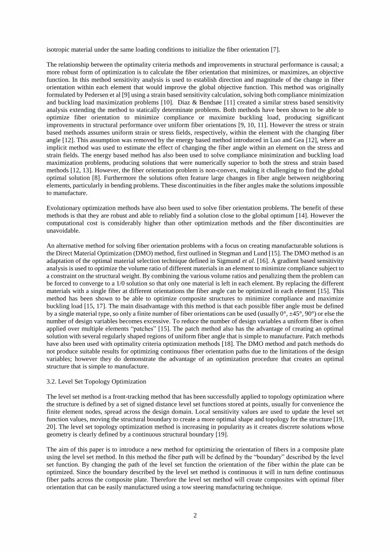
In this section the level set optimization method of fiber orientation is outlined. The level set function lsf = 0
defines the primary path of a fiber in a composite panel. The paths of the other fiber tows through the structure are
defined by constant lsf values. In this way the level set function describes a series of continuous parallel fiber paths
throughout the plate, an example of this is shown in figure 1.
Figure 1: Plot of fiber tow paths through the structure defined by lines with constant integer level set function
values. Lsf=0 line highlighted in red.
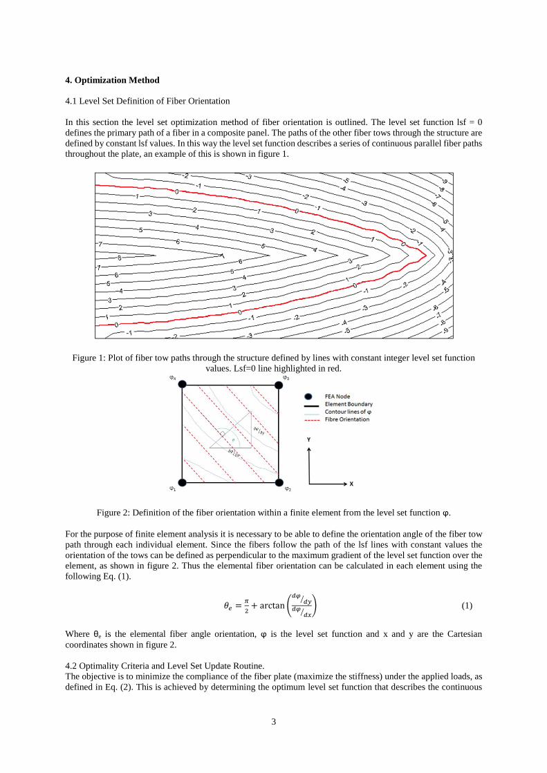
Figure 2: Definition of the fiber orientation within a finite element from the level set function ϕ.
For the purpose of finite element analysis it is necessary to be able to define the orientation angle of the fiber tow
path through each individual element. Since the fibers follow the path of the lsf lines with constant values the
orientation of the tows can be defined as perpendicular to the maximum gradient of the level set function over the
element, as shown in figure 2. Thus the elemental fiber orientation can be calculated in each element using the
following Eq. (1).
(
⁄
⁄) (1)
Where θe is the elemental fiber angle orientation, ϕ is the level set function and x and y are the Cartesian
coordinates shown in figure 2.
4.2 Optimality Criteria and Level Set Update Routine.
The objective is to minimize the compliance of the fiber plate (maximize the stiffness) under the applied loads, as
defined in Eq. (2). This is achieved by determining the optimum level set function that describes the continuous
4
fiber paths.
∑
(2)
where E is the overall compliance of the structure, C is the element stiffness matrix dependent on the fiber angle θ,
εi is the strain of element i, and n is the number of elements.
To optimize the fiber orientation local sensitivity analysis is used to update the level set function values around the
lsf = 0 line. This local update of the level set function is then extrapolated to the rest of the nodes in the structure.
The fast marching method [21] is used to update the fiber orientation throughout the entire structure, while
maintaining the evenly spaced continuous tow path definitions.
4.3 Sensitivity Analysis
The orthotropic stiffness matrix at any fiber angle θ, can be calculated in terms of the unrotated stiffness matrix C0
and the transformation matrix T(θ). So the compliance in a structure of uniform fiber angle θ is.
(3)
(4) (5)
(6)
The Q terms are calculated from the material properties, longitudinal Young’s modulus, EL, transverse Young’s
modulus, ET, the major and minor Poisson’s ratios, LT and TL, and the in plane and out of plane shear moduli, GLT,
GLW and GTW.
(7)
The sensitivity of the compliance to the fiber orientation requires Eq. (3) to be differentiated with respect to θ. Performing the matrix-vector calculation in Eq. (3) results in the equation for the compliance below.
(8)
where A are constant coefficient values shown below:
[( )] [( )] [( )]
[( )] [( )] [( )]
*( )+ *(
)+ *( )+
*( )+ *(
5
)+ *( )+
*( )+ *(
)+ *(
)+
( ) ( )
( ) ( )
( ) ( )
The resulting formula for εTCε can then be differentiated in terms of θ:
(9)
The sensitivity of the overall structural compliance to the elemental fiber angle is evaluated using the energy based
method from Luo and Gea [12]. This energy based method considers the effect of the fiber orientation on both the
strain and stress field. It has been shown to produce numerically more optimal orthotropic material structures then
the strain or stress based methods alone.
To combine the stress and strain fields as a function of fiber angle an inclusion model is used to estimate the
change in the strain and stress field caused by a change in the element fiber orientation (Δθe) in terms of the current
strain and stress, ε0 and σ0, and the energy factor α; that is defined as the ratio of the change in elemental strain
energy to the change in body strain energy caused by Δθe.
(10)
Substituting this into the objective function Eq. (2) gives the formulation.
(11)
where S is the compliance matrix, calculated from Q-1
. Eq. (17) can be solved using the formulation for εT(∂C/∂θ)ε in Eq. (8) and the equivalent formulations for εT(∂S/∂θ)ε and εT(∂C/∂θ)σ. The complete derivations can
be found in Luo and Gea [12].
Following in the sensitivity computation, Eq. (13), a new fiber angle is determined by Eq. (12).
(
| |) (12)
(
| |) (
|
|
) W
where Δθmax is the maximum allowable change in one iteration given by the user. If Δθmax is too small, it can delay
convergence. If too large, it can induce instability and oscillation during optimization.
The change in the elemental fiber angle is interpreted in terms of the level set function in order to update the
structure. The sensitivity of the elemental fiber angle to the nodal level set function values is given by
differentiating (1) with respect to the level set function.
The nodal values can be differentiated over an element from the shape functions, Ni at node i.
∑
∑
(13)
Using the standard results for differentiating the arctangent function, the sensitivity becomes,
6
(
)
(
)
(
)
[(
)
]
(14)
where ∑
and ∑
Multiplying the result, ∂θe/∂ϕi, by the result of the energy equation ∂Ø/∂θe gives the change in level set function in
node i for element e. Since each node is attached to four elements, the level set update is calculated from the
sensitivity of all four elements by (15).
∑
(15)
where j denotes the elements surrounding node i.
4.4 Initialization of the Level Set Function
Optimizing the path of the lsf = 0 line ensures the continuity of fiber paths although it limits the search space and
can easily find a local optimum. Since the solution can be highly dependent on the initial solution, a strategy for
selecting the initial solution is investigated. We found that a consistently good solution is obtained by using the
solution from an isotropic topology optimization as the starting solution. A topologically optimum solution has
near uniform strain energy along the structural boundary where lsf = 0, unless the boundary is limited by the edge
of the design domain. The structural boundary of the topological optimum is treated as the starting solution for the
fiber angle optimization problem of a continuous panel. In this paper the structure of all the test problems are
initialized using the 2D level set topology optimization method from Dunning and Kim [20].
5. Results and Discussion
To test the performance of the level set fiber orientation optimization method it is used to optimize the orientation
of orthotropic material in three simple in plane loaded test models, a cantilever beam, a centrally loaded beam
constrained at both ends, and a bridge structure loaded along the top edge, as shown in figure 3. All three models
have a 40x20 bilinear shell element mesh with the material properties EL = 137.9 GPa, ET = 10.34 GPa, LT = 0.29,
TL = 0.021, GLT = 6.89 GPa, GLW = 3.7 GPa and GTW = 6.89 GPa, and are optimized with Δθmax = 5°.
For reference, these problems were first run by the element based approach with Δθmax = 45° [12]. The optimum
solutions do not restrict the fibre angle continuity therefore the searches a larger design space at the risk of finding
an unmanufacturable solution. The best optimal results were obtained from an initial uniform fiber orientation of
0° for the cantilever and centrally loaded models and 90° for the bridge model, with the solutions shown in figure
4. The problems were also run by the level set approached discussed in Section 4. The initial solutions are obtained
from isotropic topology optimisation and are shown in figures 5a, 7a and 8a. The current implementation of the
method requires the fiber angle to be initialized from a single boundary line. To create simple single boundary the
level set topology optimization method is run without the hole insertion method [20], as demonstrated by the
cantilever beam, figure 5a. However multiple boundary results were still produced for the center loaded and bridge
beams, in these cases the longest single boundary, highlighted in red in figures 6a and 7a, were selected to initialize
the lsf = 0 line for the fiber orientation stage of the optimization procedure. In the initial and final level set function
line plots in plots figure 5, 6, 7 b and c the red line shows the current path of the lsf = 0 line.
In addition to the objective function, we introduce another metric for the comparative study, a fiber continuity
score (FCS). In each of the solutions the optimal orientation of the fiber with in each element is compared to the
eight neighboring elements. The elemental FCS is calculated from the percentage of neighboring elements whose
fiber angles differ by less than 10°, as shown in Eq.18 where is the number of elements and is the number
of elements neighboring element i. This provides a numerical value indicating the continuinty of fibre angles
between elements.
∑ *∑ {
+
∑ ( )
(16)
7
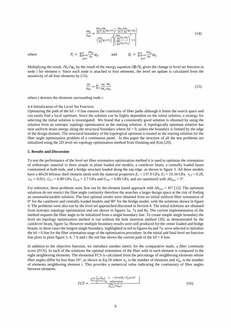
Figure 3: Test models. A: Cantilever Beam. B: Centrally Loaded Beam. C: Bridge
Figure 4: Optimal elemental fiber angle plots calculated by the elemental method using energy base sensitivity
analysis. A: Cantilever Beam. B: Centrally Loaded Beam. C: Bridge
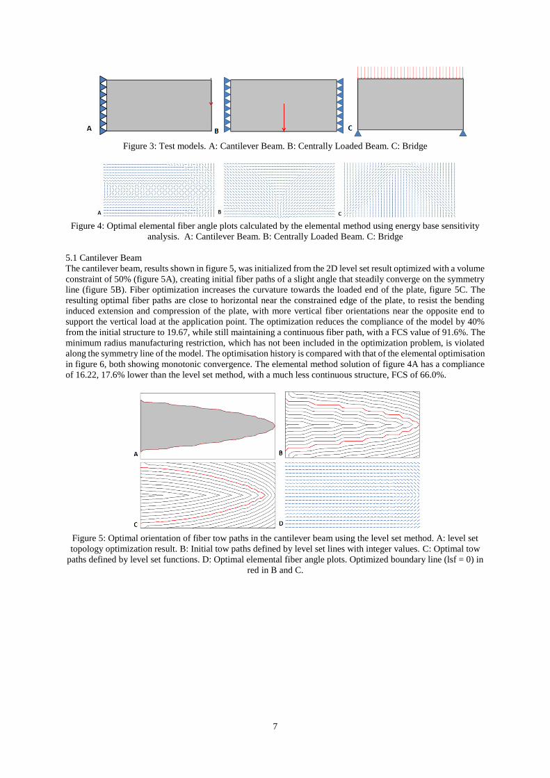
5.1 Cantilever Beam
The cantilever beam, results shown in figure 5, was initialized from the 2D level set result optimized with a volume
constraint of 50% (figure 5A), creating initial fiber paths of a slight angle that steadily converge on the symmetry
line (figure 5B). Fiber optimization increases the curvature towards the loaded end of the plate, figure 5C. The
resulting optimal fiber paths are close to horizontal near the constrained edge of the plate, to resist the bending
induced extension and compression of the plate, with more vertical fiber orientations near the opposite end to
support the vertical load at the application point. The optimization reduces the compliance of the model by 40%
from the initial structure to 19.67, while still maintaining a continuous fiber path, with a FCS value of 91.6%. The
minimum radius manufacturing restriction, which has not been included in the optimization problem, is violated
along the symmetry line of the model. The optimisation history is compared with that of the elemental optimisation
in figure 6, both showing monotonic convergence. The elemental method solution of figure 4A has a compliance
of 16.22, 17.6% lower than the level set method, with a much less continuous structure, FCS of 66.0%.
Figure 5: Optimal orientation of fiber tow paths in the cantilever beam using the level set method. A: level set
topology optimization result. B: Initial tow paths defined by level set lines with integer values. C: Optimal tow
paths defined by level set functions. D: Optimal elemental fiber angle plots. Optimized boundary line (lsf = 0) in
red in B and C.
8
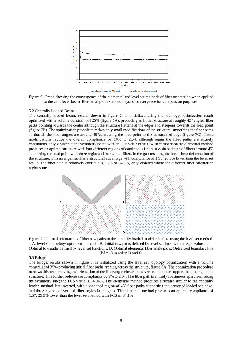
Figure 6: Graph showing the convergence of the elemental and level set methods of fiber orientation when applied
to the cantilever beam. Elemental plot extended beyond convergence for compassion purposes.
5.2 Centrally Loaded Beam
The centrally loaded beam, results shown in figure 7, is initialized using the topology optimization result
optimized with a volume constraint of 25% (figure 7A), producing an initial structure of roughly 45° angled fiber
paths pointing towards the center although the structure flattens at the edges and steepens towards the load point
(figure 7B). The optimization procedure makes only small modifications of the structure, smoothing the fiber paths
so that all the fiber angles are around 45°connecting the load point to the constrained edge (figure 7C). These
modifications reduce the overall compliance by 10% to 2.54, although again the fiber paths are entirely
continuous, only violated at the symmetry point, with an FCS value of 96.0%. In comparison the elemental method
produces an optimal structure with four different regions of continuous fibers, a v-shaped path of fibers around 45° supporting the load point with three regions of horizontal fibers in the gap resisting the local shear deformation of
the structure. This arrangement has a structural advantage with compliance of 1.98, 28.3% lower than the level set
result. The fiber path is relatively continuous, FCS of 84.9%, only violated where the different fiber orientation
regions meet.
Figure 7: Optimal orientation of fiber tow paths in the centrally loaded model calculate using the level set method.
A: level set topology optimization result. B: Initial tow paths defined by level set lines with integer values. C:
Optimal tow paths defined by level set functions. D: Optimal elemental fiber angle plots. Optimized boundary line
(lsf = 0) in red in B and C.
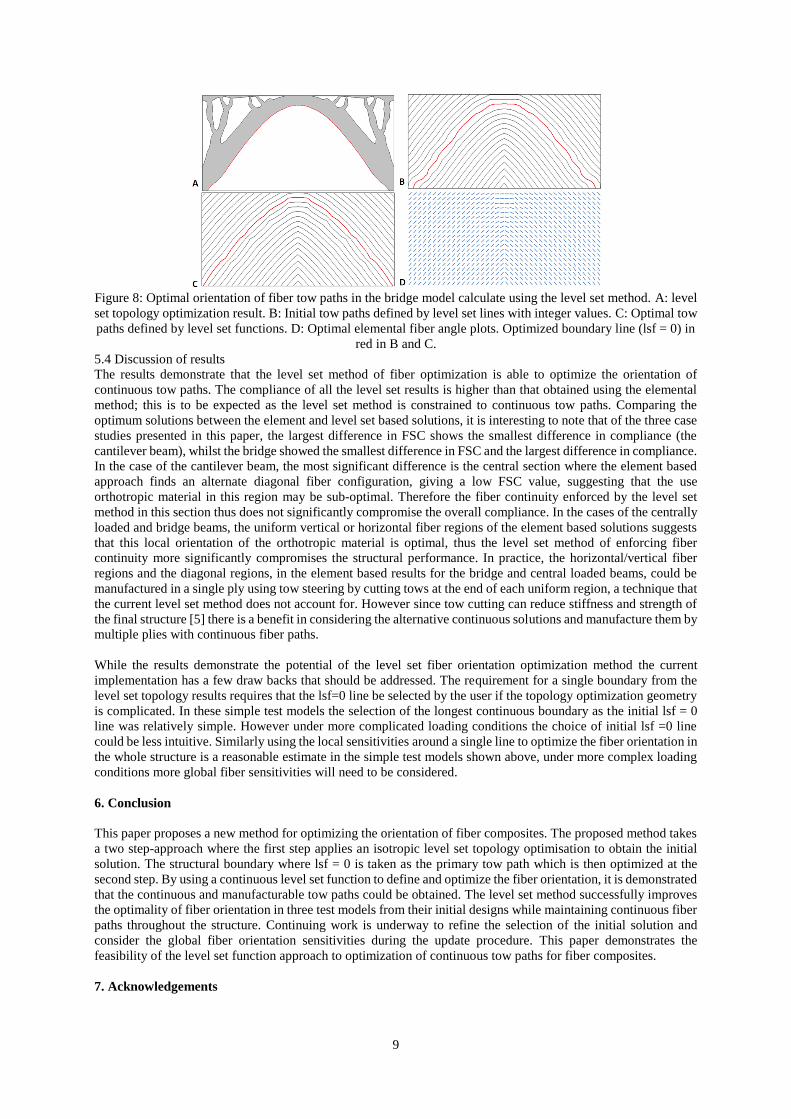
5.3 Bridge
The bridge, results shown in figure 8, is initialized using the level set topology optimization with a volume
constraint of 35% producing initial fiber paths arching across the structure, figure 8A. The optimization procedure
narrows this arch, moving the orientation of the fiber angle closer to the vertical to better support the loading on the
structure. This further reduces the compliance by 9% to 2.04. The fiber path is entirely continuous apart from along
the symmetry line; the FCS value is 94.04%. The elemental method produces structure similar to the centrally
loaded method, but inverted, with a v-shaped region of 45° fiber paths supporting the center of loaded top edge,
and three regions of vertical fiber angles in the gaps. The elemental method produces an optimal compliance of
1.57; 29.9% lower than the level set method with FCS of 84.1%
9
Figure 8: Optimal orientation of fiber tow paths in the bridge model calculate using the level set method. A: level
set topology optimization result. B: Initial tow paths defined by level set lines with integer values. C: Optimal tow
paths defined by level set functions. D: Optimal elemental fiber angle plots. Optimized boundary line (lsf = 0) in
red in B and C.
5.4 Discussion of results
The results demonstrate that the level set method of fiber optimization is able to optimize the orientation of
continuous tow paths. The compliance of all the level set results is higher than that obtained using the elemental
method; this is to be expected as the level set method is constrained to continuous tow paths. Comparing the
optimum solutions between the element and level set based solutions, it is interesting to note that of the three case
studies presented in this paper, the largest difference in FSC shows the smallest difference in compliance (the
cantilever beam), whilst the bridge showed the smallest difference in FSC and the largest difference in compliance.
In the case of the cantilever beam, the most significant difference is the central section where the element based
approach finds an alternate diagonal fiber configuration, giving a low FSC value, suggesting that the use
orthotropic material in this region may be sub-optimal. Therefore the fiber continuity enforced by the level set
method in this section thus does not significantly compromise the overall compliance. In the cases of the centrally
loaded and bridge beams, the uniform vertical or horizontal fiber regions of the element based solutions suggests
that this local orientation of the orthotropic material is optimal, thus the level set method of enforcing fiber
continuity more significantly compromises the structural performance. In practice, the horizontal/vertical fiber
regions and the diagonal regions, in the element based results for the bridge and central loaded beams, could be
manufactured in a single ply using tow steering by cutting tows at the end of each uniform region, a technique that
the current level set method does not account for. However since tow cutting can reduce stiffness and strength of
the final structure [5] there is a benefit in considering the alternative continuous solutions and manufacture them by
multiple plies with continuous fiber paths.
While the results demonstrate the potential of the level set fiber orientation optimization method the current
implementation has a few draw backs that should be addressed. The requirement for a single boundary from the
level set topology results requires that the lsf=0 line be selected by the user if the topology optimization geometry
is complicated. In these simple test models the selection of the longest continuous boundary as the initial lsf = 0
line was relatively simple. However under more complicated loading conditions the choice of initial lsf =0 line
could be less intuitive. Similarly using the local sensitivities around a single line to optimize the fiber orientation in
the whole structure is a reasonable estimate in the simple test models shown above, under more complex loading
conditions more global fiber sensitivities will need to be considered.
6. Conclusion
This paper proposes a new method for optimizing the orientation of fiber composites. The proposed method takes
a two step-approach where the first step applies an isotropic level set topology optimisation to obtain the initial
solution. The structural boundary where lsf = 0 is taken as the primary tow path which is then optimized at the
second step. By using a continuous level set function to define and optimize the fiber orientation, it is demonstrated
that the continuous and manufacturable tow paths could be obtained. The level set method successfully improves
the optimality of fiber orientation in three test models from their initial designs while maintaining continuous fiber
paths throughout the structure. Continuing work is underway to refine the selection of the initial solution and
consider the global fiber orientation sensitivities during the update procedure. This paper demonstrates the
feasibility of the level set function approach to optimization of continuous tow paths for fiber composites.
7. Acknowledgements
10
This work was funded by NASA's Fixed Wing Project under the Fundamental Aeronautics Program. We would
like to thank Dr. Chauncey Wu from NASA Langley Research Center for valuable input during this project.
8. References [1] MW. Tosh, DW. Kelly, On the design, manufacture and testing of trajectorial fibre steering for carbon fibre composite
laminates, Composites: Part A, 31, 1047-1060, 2000.
[2] Z. Gürdal, R. Olmedo, Composite laminates with spartially varying fiber orientations: variable stiffness panel concept,
AIAA/ASME/ASCE/AHS/ASC 33rd structures, structural dynamics and materials conference, Dallas, TX, USA, 1992.
[3] Z. Gürdal, R. Olmedo, In-plane response of laminates with spartially varying fiber orientations: variable stiffness concept.
AIAA Journal, 31(4),751-758, 1993.
[4] R. Olmedo, Z. Gürdal, Buckling response of laminates with spatially varying fiber orientations,
AIAA/ASME/ASCE/AHS/ASC 33rd structures, structural dynamics and materials conference,La Jola, CA, 1993.
[5] BC. Kim, K. Potter, PM. Weaver, Continuous tow shearing for manufacturing variable angle tow composites, Composites:
Part A, 43, 1347-1356, 2012.
[6] DHJA. Lukaszewicz, C. Ward, KD. Potter, The engineering aspects of automated prepreg layup: History, present and
future, Composites: Part B, 43, 997-1009, 2012.
[7] H. Temmen, R. Degenhardt, T. Raible, Tailored fibre placement optimization tool. 25th international congress of the
aeronautical sciences, Hamburg, Germany, 2006.
[8] H. Ghiasi, K. Fayazbakhsh, D. Pasini, L. Lessard, Optimum stacking sequence design of composite materials Part II:
Variable stiffness design, Composite Structures, 93, 1-13, 2010.
[9] P. Pedersen On Optimal Orientation of orthotropic materials. Structural Optimization 1, 101-106, 1989
[10] P. Pedersen On thickness and orientational design with orthotropic materials. Structural Optimization, 3, 69-78, 1991
[11] AR. Diaz, MP. Bendøse, Shape optimization of structures for multiple loading conditions using a homogenization method,
Structural Optimization 4, 17-22 1992
[12] ] JH. Luo, HC. Gea, Optimal orientation of orthotropic materials using an energy based method. Structural Optimization
15, 230-236, 1998
[13] JH. Luo, HC. Gea, Optimal bead orientation of 3D shell/plate structures, Finite elements in analysis and design, 31, 55-71,
1998
[14] D. Keller, Optimization of ply angles in laminated composite structures by a hybrid asynchronous parallel evolutionary
algorithm. Composite Structure, 92, 2781-2790, 2010
[15] J. Stegmann, E. Lund, Discrete material optimization of general composite shell structures. International Journal for
Numerical Methods in Engineering, 62, 2009-2027, 2005
[16] O. Sigmund, S. Torque, Design of materials with extreme thermal expansion using a three-phase topology optimization
method, Journal of Mechanics and Physics of Solids, 4, 1037-1067, 1997
[17] E. Lund, Buckling topology optimization of laminate multi-material composite shell structures. Composite Structures, 91,
158-167, 2009
[18] J. Zhang, WH. Zhang, JH. Zhu, An extended stress based method for orientation angle optimization of laminated
composite structures, Acta Mechanica Sinica 27(6), 977-985, 2011
[19] G. Allaire, F. Jouve, AM. Toader, Structural optimization using sensitivity analysis and a level set method. Journal of
Computational Physics, 194(1), 363-393, 2004.
[20] PD. Dunning, HA. Kim, Investigation and improvement of sensitivity computation using the area-fraction weighted fixed
grid FEM and structural optimization. Finite Elements in Analysis and Design, 47, 933-941, 2011.
[21] JA. Setian, Level set methods and fast marching methods. Cambridge University, Press, New York, 2nd edition.