Embed Size (px)
Citation preview
f) 380.
4 (1995) 911
Left, 30 (1994)
. J Electron, 80
J Pure & Appl
;
Indian Journal of Pure & Applied PhysicsVol. 44, May 2006, pp. 407-413
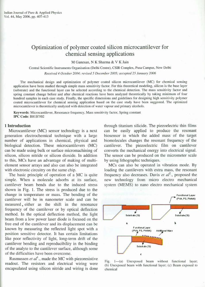
Optimization of polymer coated silicon microcantilever forchemical sensing applications
M Ganesan, N K Sharma & V K JainCentral Scientific Instruments Organisation (Delhi Centre), CSIR Complex, Pusa Campus, New Delhi
Received 4 October 2004; revised 5 December 2005; accepted 25 January 2006
The mechanical design and optimization of polymer coated silicon microcantilever (MC) for chemical sensingapplication have been studied through simple mass sensitivity factor. For this theoretical modeling, silicon is the base layer(substrate) and the functional layer can be selected according to the chemical detection. The mass sensitivity factor andspring constant change before and after chemical reactions have been analyzed theoretically by taking minimum of fourhundred samples in each case study. Finally, the specific dimensions and guidelines for designing high sensitivity polymercoated microcantilever for chemical sensing application based on the case study have been suggested. The optimizedmicrocantilever is theoretically analyzed with detection of water vapour and primary alcohols.
Keywords: Microcantilever, Resonance frequency, Mass sensitivity factor, Spring constantIPC Code: B81B7/02
1 IntroductionMicrocantilever (MC) sensor technology is a next
generation electrochemical technique with a largenumber of applications in chemical, physical andbiological detection. These microcantilevers (MC)can be made using bulk or surface micromachining ofsilicon, silicon nitride or silicon dioxide. In additionto this, MCs have an advantage of making of multi-element sensor arrays and also can also be integratedwith electronic circuitry on the same chip.
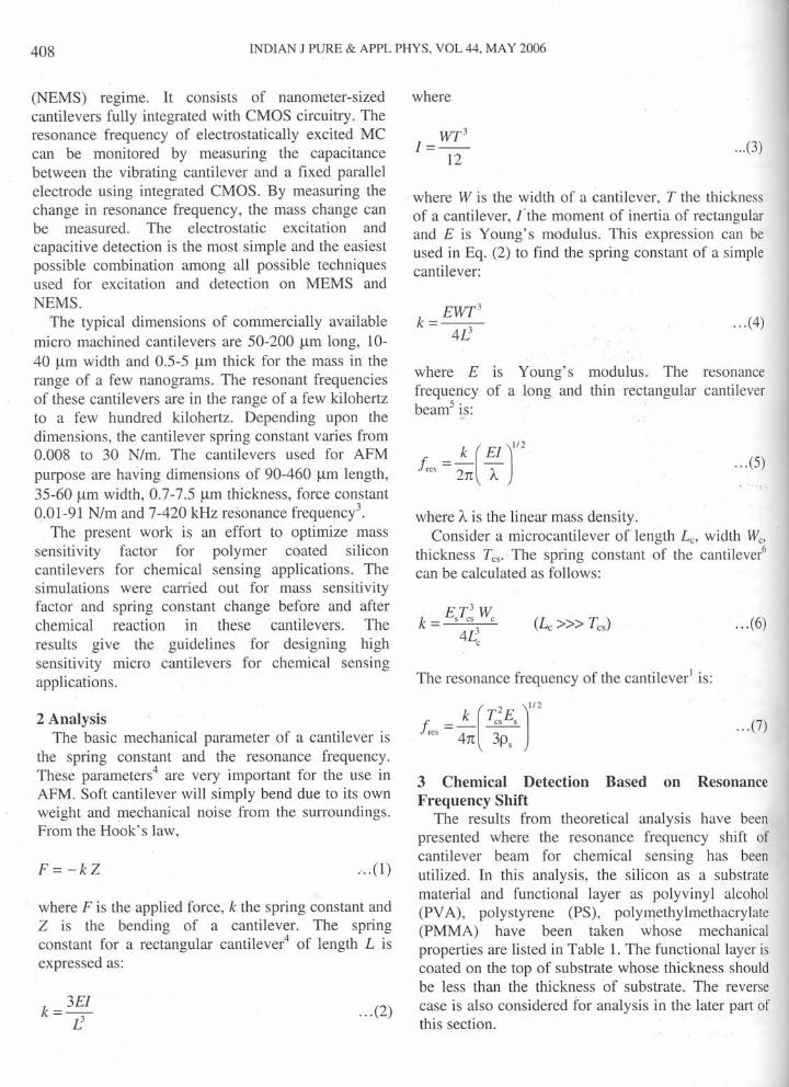
The basic principle of operation of a MC is quitesimple. When a molecule adsorbs at its surface,cantilever beam bends due to the induced stressshown in Fig. 1. The stress is produced due to thechange in temperature or mass. The bending of thecantilever will be in nanometer scale and can bemeasured ~ either as the shift in the resonancefrequency of the cantilever or by optical deflectionmethod. In the optical deflection method, the lightbeam from a low power laser diode is focused on thefree end of the cantilever and its displacement can beknown by measuring the reflected light spot with aposition sensitive detector. It has certain limitationslike poor reflectivity of light, long-term drift of thecantilever bending and reproducibility in the bindingof the analyte to the cantilever surface, although someof the difficulties have been overcome.
Rasmussen et all., made the MC with piezoresistivereadout. The resistors and electrical wiring wereencapsulated using silicon nitride and wiring is done
through titanium silicide. The piezoelectric thin filmscan be easily applied to produce the resonantbiosensor in which the added mass of the targetbiomolecules changes the resonant frequency of thecantilever. The piezoelectric film on cantileverconverts the mechanical energy into electrical signal.The sensor can be produced on the micrometer scaleby using lithographic techniques.
MCs can also be operated in vibration mode. Byloading the cantilevers with extra mass, the resonantfrequency also decreases. Davis et aP., proposed thenew technology from micro electro mechanicalsystem (MEMS) to nano electro mechanical system
functional Layerr (PVA. PS. PMMA)
iFiI----...,
a b
Fig. 1-(a) Unexposed beam without functional layer;(b) Unexposed beam with functional layer; (c) Beam exposed tochemical
408 INDIAN J PURE & APPL PHYS, VOL 44, MAY 2006
(NEMS) regime. It consists of nanometer-sizedcantilevers fully integrated with CMOS circuitry. Theresonance frequency of electrostatically excited MCcan be monitored by measuring the capacitancebetween the vibrating cantilever and a fixed parallelelectrode using integrated CMOS. By measuring thechange in resonance frequency, the mass change canbe measured. The electrostatic excitation andcapacitive detection is the most simple and the easiestpossible combination among all possible techniquesused for excitation and detection on MEMS andNEMS.
The typical dimensions of commercially availablemicro machined cantilevers are 50-200flm long, 10-40 urn width and 0.5-5 urn thick for the mass in therange of a few nanograms. The resonant frequenciesof these cantilevers are in the range of a few kilohertzto a few hundred kilohertz. Depending upon thedimensions, the cantilever spring constant varies from0.008 to 30 N/m. The cantilevers used for AFMpurpose are having dimensions of 90-460 urn length,35-60 urn width, 0.7-7.5 urn thickness, force constant0.01-91 N/m and 7-420 kHz resonance frequency'.
The present work is an effort to optimize masssensitivity factor for polymer coated siliconcantilevers for chemical sensing applications. Thesimulations were carried out for mass sensitivityfactor and spring constant change before and afterchemical reaction in these cantilevers. Theresults give the guidelines for designing highsensitivity micro cantilevers for chemical sensingapplications.
2 AnalysisThe basic mechanical parameter of a cantilever is
the spring constant and the resonance frequency.These parameters" are very important for the use inAFM. Soft cantilever will simply bend due to its ownweight and mechanical noise from the surroundings.From the Hook's law,
F= -kZ .'.. (1)
where F is the applied force, k the spring constant andZ is the bending of a cantilever. The springconstant for a rectangular cantilever" of length L isexpressed as:
... (2)
where
WT3
1=--12
... (3)
' ..'"
Silicon
PolyvinyPolystyrePolymetrmethacry"Principl,Fundarneicnc pres* www.p<
where W is the width of a cantilever, T the thicknessof a cantilever, {the moment of inertia of rectangularand E is Young's modulus. This expression can beused in Eq. (2) to find the spring constant of a simplecantilever:
EWT3
k=--4/J
... (4)
Acharthe J
dens
and i+ Ef
layerthe II
whenfrequtas:
t.: =
... (7)
Thi.mass .functi:the resthe to,implieinversethe sucantilereactio
where E is Young's modulus. The resonancefrequency of a long and thin rectangular cantileverbeam" is:
... (5)
Material
where A is the linear mass density.Consider a microcantilever of length L; width We,
thickness Tcs. The spring constant of the cantilever"can be calculated as follows:
.. .(6)
The resonance frequency of the cantilever' is:
[
2 ]1121. =~ TesEsres 4n 3ps
3 Chemical Detection Based on ResonanceFrequency Shift
The results from theoretical analysis have beenpresented where the resonance frequency shift ofcantilever beam for chemical sensing has beenutilized. In this analysis, the silicon as a substratematerial and functional layer as polyvinyl alcohol(PV A), polystyrene (PS), polyrnethylmethacrylate(PMMA) have been taken whose mechanicalproperties are listed in Table 1. The functional layer iscoated on the top of substrate whose thickness shouldbe less than the thickness of substrate. The reversecase is also considered for analysis in the later part ofthis section.
GANES AN et al.: OPTIMIZATION OF POLYMER COATED SILICON MICROCANTILEVER 409
After surface modifications, the mechanicalcharacteristics of microcantilever beam change due tothe formation of a functional layer. The linear massdensity of the modified cantilever will now become':
Ar= Ps As + Pr Ar ... (8)
and its flexural rigidity will be redefined as E I = Es Is+ E, Ir where s andjrepresent substrate and functionallayers, respectively. Now, the moment of inertia ofthe modified beam? will also change to:
, ... (10)
T, = WJ;~+ W,T.( Y, J; J ... (9)
3 ( )2WJcf i:If =--+WcTcf --~s +Y.,12 2
where Yc is the centre of mass. The new resonancefrequency after surface modification will be expressedas:
1. - k (E I + E I J"2new-- 55 ff
2n A f
... (11)
This expression shows that both the stiffness andmass loading affect the resonance frequency? If thefunctionalized cantilever is exposed to vapour sample,the results in swelling of the polymer layer coated on"the top of cantilever surface. The mass increaseimplies decreasein resonance frequency, since it isinversely proportional to applied mass. This changesthe surface' stress, which results in bending of acantilever. The amount of mass increased afterreaction is directly related with the number of
Table l-Microcantilever Sensor material properties*
Material Name Young'sModulus
(Pa)
Density(Kg/m3)
Remarks
Silicon 2.33e3l.05e3l.04e3
O.75e3
Substrate
Functional Layer----do-------do---
l.7xl0ell
7e93.2e93e9
PolyvinylalcoholPolystyrenePolymethylmethacrylate*Principle Source semiconductor material properties;Fundamentals of microfabrication, Marc J. Madou, Marc Madou,eRC press, 1997.* www.polymerscience.com/copolymers
molecules deposited or absorbed by the functionallayer. Now, the final resonance frequency due to theincrease of mass can be expressed as:
... (12)
where p; Pr are the densities of substrate andfunctional layers, respectively; As, Ar are the cross-sectional areas of substrate and functional layers,respectively; M is the additional mass added at theend of a cantilever beam due to chemical reaction. Ifwe know the order of applied mass during the reactionthen we can estimate the shift in resonance frequency,M, from Eqs (11) and (12).
t1j = f new - ir.nal ... (13)
4 Cantilever Fabrication. Materials used to fabricate micromachinedcantilevers are silicon, silicon nitride, silicon carbideand silicon dioxide. Commercially availablecantilevers are made with silicon-based materialscoated with thin layer of gold, silver or aluminium forbetter optical readout. The composite cantilevers arevery much prone to thermal noise due to biomaterialeffects". Increasing the ratio of substrate to functionallayer thickness can eliminate this.
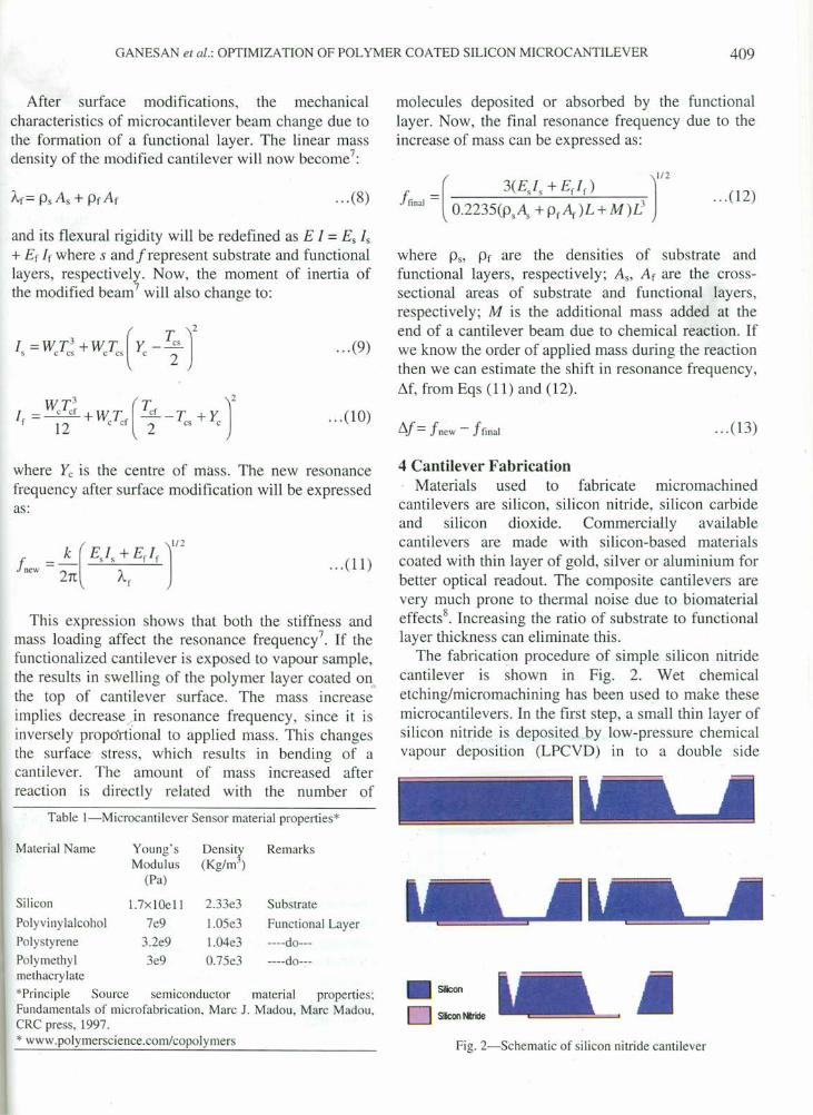
The fabrication procedure of simple silicon nitridecantilever is shown in Fig. 2. Wet chemicaletching/micromachining has been used to make thesemicrocantilevers. In the first step, a small thin layer ofsilicon nitride is deposited by low-pressure chemicalvapour deposition (LPCYD) in to a double side
Silicon
o Siicon t.iride
Fig. 2-Schematic of silicon nitride cantilever
410 INDIAN J PURE & APPL PHYS, VOL 44, MA Y 2006
polished silicon crystal wafer. In the second step, adeep etch pattern is prepared in the silicon nitridelayer on the non-cantilever side of the wafer usingphotolithography and reactive ion etching. The nextstep is etching of anisotropic surface with KOH untilsilicon wafer attains to required thickness. Therequired shape is achieved in the silicon nitride byusing reactive ion etching and a few nanometers thickgold layer was deposited on the topside of thecantilever. Finally the cantilever is realized by etchingthe remaining portion of silicon in KOH using bulkmicromachining. The experimental work is inprogress to compare our theoretical results with theexperimental observations.
5 Results and Discussion5.1 Detection of water vapour
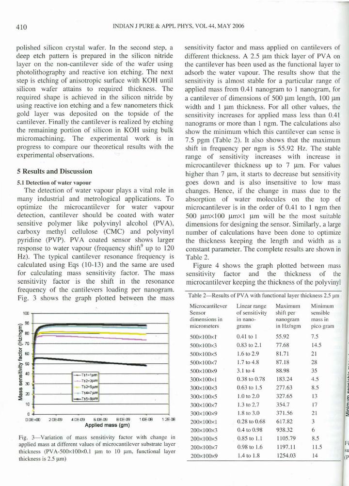
The detection of water vapour plays a vital role inmany industrial and metrological applications. Tooptimize the microcantilever for water vapourdetection, cantilever should be coated with watersensitive polymer like polyvinyl alcohol (PYA),carboxy methyl cellulose (CMC) and polyvinylpyridine (PYP). PYA coated sensor shows largerresponse to water vapour (frequency shift" up to 120Hz). The typical cantilever resonance frequency iscalculated using Eqs (10-13) and the same are usedfor calculating mass sensitivity factor. The masssensitivity factor is the shift in the resonancefrequency of the cantilevers loading per nanogram.Fig. 3 shows the graph plotted between the mass
1rn~----------------------------------~
O~----~----~----~----~~----T---~O.OE-+UJ 2.0E·09 4.0E·09 5.0E·09 B.OE·09 tOE·DB 1.2E·DB
Applied mass (gm)
Fig. 3-Variation of mass sensitivity factor with. change inapplied mass at different values ~f microcantilever substrate layer .thickness (PVA-500xl00xO.l urn to 10 urn, functional layerthickness is 2.5 urn)
sensitivity factor and mass applied on cantilevers ofdifferent thickness. A 2.5 urn thick layer of PYA onthe cantilever has been used as the functional layer toadsorb the water vapour. The results show that thesensitivity is almost stable for a particular range ofapplied mass from 0.41 nanogram to 1 nanogram, fora cantilever of dimensions of 500 urn length, 100 urnwidth and 1 urn thickness. For all other values, thesensitivity increases for applied mass less than 0.41nanograms or more than 1 ngm. The calculations alsoshow the minimum which this cantilever can sense is7.5 pgm (Table 2). It also shows that the maximumshift in frequency per ngm is 55.92 Hz. The stablerange of sensitivity increases with increase inmicrocantilever thickness up to 7 urn. For valueshigher than 7 urn, it starts to decrease but sensitivitygoes down and is also insensitive to low masschanges. Hence, if the change in mass due to theabsorption of water molecules on the top ofmicrocantilever is in the order of 0.41 to 1 ngm then500 umxl Ou urnxl urn will be the most suitabledimensions for designing the sensor. Similarly, a largenumber of calculations have been done to optimizethe thickness keeping the length and width as aconstant parameter. The complete results are shown inTable 2.
Figure 4 shows the graph plotted between masssensitivity factor and the thickness of themicrocantilever keeping the thickness of the polyvinyl
Table 2-Results of PV A with functional layer thickness 2.5 f.lITI
Microcantilever Linear range Maximum MinimumSensor of sensitivity shift per sensibledimensions in in nano- nanogram mass inmicrometers grams in Hz/ngm pico gram
500x1OOxl" 0.41 to I 55.92 7.5
500xlOOx3 0.83 to 2.1 77.68 14.5
500xl00x5 1.6 to 2.9 81.71 21
500xlOOx7 1.7 to 4.8 87.18 28
500xlOOx9 3.1 to 4 88.98 35
300x100x1 0.38 to 0.78 183.24 4.5
300xlOOx3 0.63 to 1.5 277.63 8.5
300xl00x5 1.0 to 2.0 327.65 13
300xlOOx7 1.3 to 2.7 354.7 17
300xl00x9 1.8 to 3.0 371.56 21
200xlQOxi 0.28 to 0.68 617.82 3
200xl00x3 0.4 to 0.98 938.32 6
200xl00x5 0.85 to 1.1 1105.79 8.5
200x100x7 0.98 to 1.6 1197.11 11.5
200xlOOx9 1.4 to 1.8 1254.03 14
alcoholirnportaIS greatsensitiviIncreaseto the lifunction;Fig. 4) .:substratefunction,the thickthan that
The ttminimurrcantilevs,
oOOE-<oo
Fig. 4-Varisubstrate la5feapplied massthickness is 2,
40 -...,.~~E~35 ••• __
!:l30-#===lU
E 25il===CD
~ 20iF==='in~ 15iI==~rn~ 10'11===
,~ 5iF== ••••••
~ Oif==~=o
Fig. 5-Variatisubstrate layer I
(PV A width 100
mtilevers of. of PYA onanal layer tolOW that thelar range ofmogram, forigth, 100 urnr values, thess than 0041ulations alsocan sense 1S
ie maximum~.The stableincrease in
. For valuesut sensiti vi tyo low mass;
s due to thethe top of) I ngm thennost suitableiilarly, a large~ to optimize
width as a, are shown in
letween massess of thethe polyvinyl
hickness 2.5 urn
Minimumsensiblemass inpico gram
7.5
14.5
21
28354.58.5
1317
21
368.511.5
14
GANESAN et al.: OPTIMIZATION OF POLYMER COATED SILICON MICROCANTILEVER 411
alcohol (PYA) functional layer fixed at 2.5 urn. Theimportant finding is that if functional layer thicknessis greater than the substrate thickness, the masssensitivity is negative. It starts to decrease withincrease in cantilever mass. This inverse effect is dueto the large difference between the substrate and afunctional layer Young's modulus (Table 1 andFig. 4). This inverse effects tarts changing when thesubstrate thickness approaches the thickness of thefunctional layer. These observations suggest keepingthe thickness of the functional layer always lesserthan that of the cantilever.
The third graph in Fig. 5 shows the plot of theminimum mass that can be sensed by a particularcantilever versus the thickness of the canti lever,
so
-"-- -~
~ /'1,\ ./ ~1-1ngm
----J.42= 3n gm.:-- MJ=5ngm
M4=Tngm
f()
ElOClc
~60
is~50~40~aiIl'"'"~20::;
10
oD.OE-+OJ 2DE-Cli 4DE·Cli D.DE-DE 80E-Cli 1 OE-05 1.2E-05
Microcantilever thickness (m)
Fig. 4-Variation of mass sensitivrty factor with change insubstrate layer thickness of microcantilever at different values ofapplied mass CPVA-500xlOOxO.l 11m to 10 11m, functional layerthickness is 2.5 11m)
40EOl 35.s
---.,._---- --------------- .- - ---~L1=500J1ll'1
-&-L2=30011m /'/='A=-L320wm
--/.,/ ..> »-> I
// .s-:::
.r" ~iii=
III 30III
"'E 25Q)
:g 20'iji
5i 15rnE 10~.§ 5I:
~ 0o 2 4 6 8
Microcantilever thickness (urn)
Fig. 5-Variation of minimum sensible mass with change insubstrate layer thickness at different values of cantilever lengthsCPVA width 100 11mand functional layer thickness 2.5 urn)
keeping the functional layer thickness 2.5 urn. Fromthese results, one can estimate the minimum masschange required by the sensor to produce the outputsignal. Based on this estimation, the functional layerthickness can be selected for a particular dimension ofmicrocantilever sensor.
5.2 Detection of primary alcohols .Primary alcohol is another important chemical,
which is to be sensed in many food processing andother industries. The silicon cantilever is optimizedwith functional layers of poly methyl metha acrylate(PMMA), polystyrene (PS) that are more sensitive toprimary alcohols. The largest and the fastestcantilever responses in both static and dynamic modesare observed in methanol, which is the smallestanalyte molecule among the primary alcohols. PMMAcoated silicon cantilever exposed to methanol vapourproduces 130 picograms of mass change and 20 Hzfrequency shift.
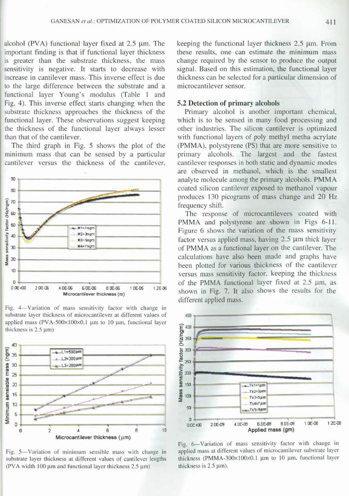
The response of microcantilevers coated withPMMA and polystyrene are shown in Figs 6-11.Figure 6 shows the variation of the mass sensitivityfactor versus applied mass, having 2.5 um thick layerof PMMA as a functional layer on the cantilever. Thecalculations have also been made and graphs havebeen plotted for various thickness of the cantileverversus mass sensitivity factor, keeping the thicknessof the PMMA functional layer fixed at 2.5 urn, asshown in Fig. 7. It also shows the results for thedifferent applied mass.
450 -..==~============~E400t~~::~::::::~~~~~~~~::::~\01 r-~ 350 -=--""==, ==------:s .o 3JO k==~~---~~====i:'0~250L-===,,============jj.?:'
~ 2DOjt:::::::::::::~~~~~;;::::::::::::;;;:::::::J'(jj
~ 150 --=Ts1=IJ11l'1
rn _TS2=3I1mil============ij::l 100 Ts3=511m :~ nwJ1ll'1 !
50 =--TS 5=9J1Il'1 !I
10
o I " I 1D.DEtllO 2.0E-09 4.0E-09 6_0E-09 8.0E-D9 lDE·(lJ 1.2E·(lJ
Applied mass (gm)
Fig. 6-Variation of mass sensinvity factor with change inapplied mass at different values of microcantilever substrate layerthickness CPMMA-300xlOOxO.! urn to 10 J..l1l1, functional layerthickness is 2.5 urn).
412 INDIAN J PURE & APPL PHYS, VOL 44, MAY 2006
450
-- >--,.•...
~
_Ml-lngm
-M2=3ngm
~ M3=5ngm~M4=7ngm
~ _M5=9n~m
400
/'rI
I
_Ts1=1J1Ol-Ts2=311m
Ts3=511m~Ts4=711m_Ts5=9J1Ol
40
~35.sIZ 30lUE 25CII
~ 20'iij:ii 151/1
E 10.::lE'c 5
~ O·I
400
~"::l50c·
~ 300
.s 250
~>- 200
=s:~ 150cCIIIII 1001/1
::I:E 50
oO.OE+OO 20E-06 4.0E-06 6.0E-06 B.OE-06 1.0E-05 1.2E-05
Microcantilever substrate layer thickness (m)
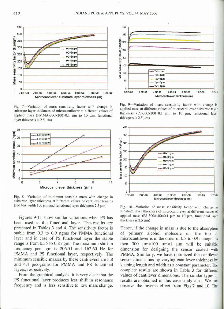
Fig. 7-Variation of mass sensitivity factor with change insubstrate layer thickness of microcantilever at different values ofapplied mass (PMMA-300x100xO.I urn to 10 urn, functionallayer thickness is 2.5 urn)
3D~-----------=======================~ECI ...- Ll=500llm.s 25 L2=300llml------..,."'-------~::l =R= L3=200llm~ 2D~==~~~~~====~~==========~~~=-1CII
~ 15~============~~======~~~==========--1'iijc~ lD~-======~~====~~~==~~~~========---1EE 5+-==~~~~~~~====================----!'c~ D~=====T======~=====T======~=====4
o
350
ECl 300
~::- 250
il'"~ 200
>~ 150c:GltJ)
lZ 100
'":::;;50
oO.OE+OO 2.0E-09 4.0E-09 a.OE-09 B.OE-09 1.0E-OS 1.2E-OB
Microcantilever thickness (m)
Fig. 9-Variation of mass sensitivity factor with change inapplied mass at different values of microcantilever substrate layerthickness (PS-300x100xO.1 urn to 10 urn, functional layerthickness is 2.5 urn)
Arn~------------------------------------_,360 04---------
graphsare as si
2 4 6 B
Microcantilever thickness (urn)
Fig. 8-Variation of minimum sensible mass with change insubstrate layer thickness at different values of cantilever lengths(PMMA width 100 urn and functional layer thickness 2.5 urn)
Figures 9-11 show similar variations when PS hasbeen used as the functional layer. The results arepresented in Tables 3 and 4. The sensitivity factor isstable from 0.3 to 0.9 ngms for PMMA functionallayer and in case of PS functional layer the stablerange is from 0.35 to 0.8 ngm. The maximum shift infrequency per ngm is 206.51 and 162.60 Hz forPMMA and PS functional layer, respectively. Theminimum sensible masses by these cantilevers are 3.8and 4.4 picograms for PMMA and PS functionallayers, respectively.
From the graphical analysis, it is very clear that thePS functional layer produces less shift in resonancefrequency and is less sensitive to low mass change.
_to11=lngm~to12=3ngm
M3=5ngmf=.===========---I-><-- M4=7ngm_M5=9ngm
Fig. 1subsrr,(PS wi
Tat
Micrcsensadimermicro
500xl
500xl
500xl
500xl300xl300xl,
300xll
300xll300xl(
200~(
200xl(
200xlC
200xlC
200xlO
6 ConclOptin
minimualcoholsilicon iapplicatitowardslayers th
10
O~====~==~====-r====~~==~==~o OE-t{)O 2.0E-OO ·\oE-OO 6.0E-OO B.OE-06 1.0E-05 1.2E.Q5
Microcantilever thickness (m)
Fig. lO-Variation of mass sensitivity factor with change insubstrate layer thickness of microcantilever at different values ofapplied mass (PS-300x100xO.l urn to 10 urn, functional layerthickness is 2.5 urn)
Hence, if the change in mass is due to the absorptionof primary alcohol molecule on the top ofmicrocantilever is in the order of 0.3 to 0.9 nanogramsthen 300 umxl Ot) umxl urn will be suitabledimension for designing the sensor coated withPMMA. Similarly, we have optimized the cantileversensor dimensions by varying cantilever thickness bykeeping length and width as a constant parameter. Thecomplete results are shown in Table 3 for differentvalues of cantilever dimensions. The similar types ofresults are obtained in this case study also. We canobserve the inverse effect from Figs 7. and 10. The
I
·08 1.2E-OB
change inistrate layerional layer
·05 1.2E-05
change init values oftional layer
bsorptiontop of
anogramssuitable
ted with.antilever.kness byieter. Thedifferent
. types of, We cani 10. The
GANESAN et al : OPTIMIZATION OF POLYMER COATED SILICON MICROCANTILEVER
4or-----------------------------~~ 35 -t------lE-m 30 t----4~~~~~~----~~~---1IVE25t-----------------~~~----------1Q)~20t--------~~~----~~~--1
·in~ 15 t-----~~~--~~~~~--~--I510t---~~~~~~~~~~c=~------1,~ 5 I--,~:::::,...-...dr.=--------------I~ 0 +------.-------.-------r-------,------l
o 2 4 6 8Microcantilever thickness (Jl m)
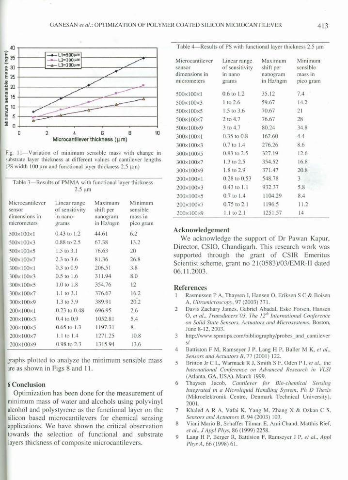
Fig, ll--Variation of minimum sensible mass with change insubstrate layer thickness at different values of cantilever lengths(PS width 100 urn and functional layer thickness 2.5 urn)
Table 3--Results of PMMA with functional layer thickness2.5 prn
Microcanti lever Linear range Maximum Minimumsensor of sensitivity shift per sensibledimensions in in nano- nanogram mass inmicrometers grams in Hz/ngrn pico gram
500xl00xl 0.43 to 1.2 44,61 6.2
500xlOOx3 0.88 to 2,5 67.38 13.2
500x100x5 1.5t03.1 76,63 20
500xl00x7 2,3 to 3.6 81.36 26.8
300xl00xl 0.3 to 0,9 206.51 3.8
300xl00x3 0.5 to 1.6 311.94 8,0
300xl00x5 1.0 to 1.8 354.76 12
300xlOOx7 1.1 to 3,1 376.67 16.2
300xlOOx9 1.3 to 3.9 389.91 20'.2
200xlOOxi 0.23 to 0.48 696,95 2.6
200x100x3 0.4 to 0.9 1052,81 5.4
200xlOOx5 0,65 to 1.3 1197.31 8
200xlOOx7 l.I to 1.4 1271.25 10.8
200xl00x9 0.98 to 2.3 1315,94 13,6
graphs plotted to analyze the minimum sensible massare as shown in Figs 8 and 11.
6 ConclusionOptimization has been done for the measurement of
minimum mass of water and alcohols using polyvinylalcohol and polystyrene as the functional layer on thesilicon based microcantilevers for chemical sensingapplications. We have shown the critical observationtowards the selection of functional and substratelayers thickness of composite microcantilevers.
413
10
Table 4--Results of PS with functional layer thickness 2.5 urn
Microcantilever Linear range, Maximum Minimumsensor of sensitivity shift per sensibledimensions in in nano nanogram mass inmicrometers grams in Hz/ngm pico gram
500x100xl 0.6 to 1,2 35.12 7.4
500x100x3 1 to 2.6 59.67 14,2
500x100x5 1.5 to 3.6 70.67 21
500x100x7 2 to 4.7 76.67 28
500xl00x9 3 to 4.7 80.24 34.8
300x100xl 0.35 to 0.8 162.60 4.4
300xl00x3 0.7'to 1.4 276.26 8.6
300x100x5 0.83 to 2.5 327.19 12.6
300xl00x7 1.3 to 2.5 354.52 16.8
300xl00x9 1.8 to 2.9 371.47 20.8
200x100x1 0.28 to 0.53 548,78 3
200xl00x3 0.43 to 1.1 932.37 5.8
200xl00x5 0.7 to 1.4 1104.29 8.4
200xl00x7 0,75 to 2.1 1196.5 11.2
200xl00x9 1.1 t02,1 1251.57 14
AcknowledgementWe acknowledge the support of Dr Pawan Kapur,
Director, CSIO, Chandigarh. This research work wassupported through the grant of CSIR EmeritusScientist scheme, grant no 21(0583)/03/EMR-II dated06.11.2003.
ReferencesI Rasmussen P A, Thaysen J, Hansen 0, Eriksen S C & Boisen
A, Ultramicroscopy, 97 (2003) 371.2 Davis Zachary James, Gabriel Abadal, Esko Forsen, Hansen
0, et al., Transducers 'OJ, The i2,h International Conference011 Solid State Sensors, Actuators and Microsystems. Boston,June 8-12, 2003,
3 http://www.spmtips.comlbibl iography/probes_and_canti levers/
4 Battiston F M, Ramseyer J P, Lang H P, Baller M K, et al.,Sensors and Actuators B, 77 (200 I) 122.
5 Britton Jr C L, Warmack R J, Smith S F, Oden P J, et 01., theInternational Conference on Advanced Research ill VLSI(Atlanta, GA, USA), March 1999,
6 Thaysen Jacob, Cantilever for Bio-chemical SensingIntegrated in a Microliquid Handling System, Ph D Thesis(Mikroelektronik Centre, Denmark Technical University),2001.
7 Khaled A R A, Vafai K, Yang M, Zhang X & Ozkan C S,Sensors and Actuators B, 94 (2003) 103.
8 Viani Mario B, Schaffer Tilman E, Ami Chand, Matthis Rief,et al. J Appi Phys, 86 (1999) 2258.
9 Lang H P, Berger R, Battision F, Ramseyer J P, et al., AppiPhys A, 66 (1998) 61.