Embed Size (px)
Citation preview
Optical Spatial Modulation with Diversity Combinerin Dual-Hops Amplify-and-Forward Relay Systems OverAtmospheric Impairments
Kehinde Oluwasesan Odeyemi1 • Pius Adewale Owolawi2 •
Viranjay M. Srivastava1
Published online: 19 June 2017� Springer Science+Business Media, LLC 2017
Abstract In this paper, we analyzed a dual-hop optical spatial modulation channel state
information-assisted amplified and forward (AF) relay system with spatial diversity
combiner under the influence of gamma-gamma atmospheric turbulence induced fading
and pointing error impairments. Maximum ratio combiner (MRC) and equal gain combiner
(EGC) with heterodyne detection are considered at the destination as mitigation tools to
improve the system error performance. The statistical characteristics of AF relay in terms
of moment generating function (MGF), probability density function and cumulative den-
sity function are derived for both impairments. Based on these expressions, the average
pairwise error probability for each of the combiners under study is determined and the
average bit error rate (ABER) for the system is given by using union bounding technique.
By utilizing the derived ABER expressions, the effective capacity for the considered
system is then obtained. The effect of turbulence strength ranging from weak to strong
levels and pointing errors in terms of beam width and jitter displacement are studied. The
numerical results obtained show that the more the turbulence strength and/or pointing error
increases, the more the error rate and effective capacity of the system deteriorates. Under
the same conditions, the results confirmed that MRC system offers an optimal performance
compared with EGC.
Keywords Free space optical systems � Dual-hops transmission � Atmospheric
turbulence � Spatial modulation � Diversity combiners � Amplified and
forward relay
& Kehinde Oluwasesan [email protected]
1 Department of Electronic Engineering, Howard College, University of KwaZulu-Natal,Durban 4041, South Africa
2 Department of Computer Systems Engineering, Tshwane University of Technology, Pretoria, SouthAfrica
123
Wireless Pers Commun (2017) 97:2359–2382DOI 10.1007/s11277-017-4612-6
1 Introduction
Recently, there is tremendous increase in the need of high data and multimedia services
such as high speed internet, video conferencing, live streaming which has led to the
congestion in radio frequency (RF) spectrum. This has led to the need of changing from RF
carrier to optical carrier [1]. Consequently, Free Space Optical (FSO) communication
system has been proposed as alternative solution to this problem in recent times due to its
various advantages. These include power consumption, cheap installation and operational
cost, license-free spectrum, large bandwidth in the capacity of order of gigabytes, high
level of security compare to RF systems counterpart [2, 3]. However, with these great
attributes, the performance of FSO communication system highly suffers from many
challenges. These challenges include atmospheric turbulence induced fading due to fluc-
tuation in the refraction index as a result of inhomogeneous variation in temperature and
pressure along the FSO link [4]. Hence, various statistical distributions have been proposed
to model the atmospheric turbulence along the FSO link. One of such is lognormal dis-
tribution which is proposed for weak turbulence over a distance of less than 1 km [5]. Also,
the K-distribution and negative exponential distribution have been studied to fit and offer
accurate result for saturated turbulence strength over a long distance of several kilometers
[6, 7]. Furthermore, Andrew et al. [8] proposed Gamma–Gamma distribution as the best
distribution that agrees well with experimental data to model atmospheric turbulent from
weak to strong levels. In addition to atmospheric turbulence, pointing error effect can also
degrade the performance of FSO system as a result of building sway caused by dynamic
wind loads, thermal expansion and weak earthquake. These cause vibrations in the
transmitted beam leading to misalignment between the transmitter and receiver and limit
the system performance [9]. Beside the building sway, as the link distance between the
transmitter and receiver increases, the more the misalignment effect becomes pronounced,
especially over a distance of 1 km or more [10]. The combined effect of these impairments
on FSO link has been studied in literatures [11–13] and different techniques have been
suggested to improve the system performance and availability over a long distance.
Studies have shown that the atmospheric turbulence induced fading and pointing error
issues along the FSO link can be mitigated by using relay transmission technique [14]. This
technique involves scaling down the distance between the transmitter and receiver through
the use of relay hops in order to reduce the problem of a single transmitter to reach its
intended target with necessary Signal to Noise Ratio (SNR). This concept was first
explored by Acampora, and Krishnamurthy in [15], and few years later, the effectiveness
of the relay system over a large coverage area was later studied in [16, 17]. The scheme has
advantage of increasing the wireless systems coverage area to several kilometers without
the needs of large power at the transmitter and relay units. It can also provide high data rate
with low bit error at the end-to-end communication [18]. In this case, relay protocol can be
classified into two and these include Decode-and-Forward (DF) relay that decodes any
received signal from the source, re-encodes and then re-transmits the decoded information
to the destination. This relay system is called regenerative relay system. The other type is
Amplified–and-Forward (AF) relay which amplifies any incoming signal from the source
and retransmits it to the destination without performing any sort of decoding and this is
called non-regenerative relay system [19, 20].
Dual-hop relay transmission with AF protocol has been recently proposed for FSO
links. For instance, in [21], On/Off Key (OOK) modulation was used to study the capacity
performance of FSO dual-hops AF relay system with direct detection at the receiving end.
2360 K. O. Odeyemi et al.
123
However, OOK modulation scheme requires selecting adaptive thresholds appropriately in
order to achieve optimal performance, but it also suffers from poor power efficiency [22].
Moreover, Aggarwal et al. [23] investigate the performance of Subcarrier Intensity
Modulation (SIM) dual-hops CSI-assisted AF relay with direct detection over turbulence
channel with pointing error. However, the SIM modulation technique employed in this
study offers a significantly higher transceiver complexity as the number of subcarrier
increases. It also causes poor optical average power efficiency due to the increase in the
number of required DC biases [24]. Moreover, a coherent FSO AF relaying system was
considered by Pack et al. [25] in which the outage probability performance of the system
was studied. Nevertheless, the proposed system is a single input singe output (SISO) which
is usually prone to pointing errors.
The concept of Spatial Modulation (SM) has been proposed as migration technique in
FSO communication systems as it was found useful in [26–28] to improve the system error
performance. Thus, based on our study, it shows that this type of modulation scheme has
been investigated with relay technology mostly in RF wireless systems [29–32] but has not
been taken into consideration in FSO systems. SM has been known to be an efficient low
complex Multiple Input Multiple Output (MIMO) technique compared with other con-
ventional MIMO schemes. At a specific instance, it allows transmission of signal from the
activated antenna while other antennas remain idle [33]. This scheme has advantages of
avoiding inter-channel interference, eliminating the needs of inter-antenna synchroniza-
tion, and provides a robust system against channel estimation errors [34, 35]. Moreover, in
many FSO research studies, Spatial Diversity (SD) combiner has been extensively con-
sidered to combat turbulence fading and pointing errors in order to improve the signal
strength over a long distance [36]. The most common employed combiner includes
maximum ratio combiner (MRC), equal gain combiner (EGC) and selection combiner (SC)
[37]. Arguably, the combination of SM with diversity combiner as a powerful mitigation
tool against fading impairments has not been investigated in FSO relaying systems.
Motivated by this fact, we present the analysis of average BER and effective capacity of a
dual-hop spatial modulation CSI-assisted AF relay system with diversity combiner over
atmospheric turbulence and/or pointing error. In this case, the close form expression for the
end-to-end SNR MGF, PDF and CDF are derived. Utilizing these results, the APEP for
each combiner is determined and generic close form expression for the proposed system
ABER is then obtained using union bounding technique. In consequence, the effective
capacity for the system is determined through the derived ABER.
The rest of this paper is organized as follows: Sect. 2 presents the system model and the
channel statistical model is discussed in Sect. 3. In Sect. 4, the statistical characteristics of
end-to-end SNR are presented, while Sect. 5 presents the performance analysis of the
system. Numerical and simulation results for the system performance, with their inter-
pretation are presented in Sect. 6. Finally, the concluding remarks are outlined in Sect. 7.
2 System Model
Figure 1 illustrates a dual-hop SM-based relay FSO system with the source (S) as trans-
mitter, destination (D) as receiver and Relay (R). We assume that the S-to-R and R-to-D
links are independent, non-identical channel and heterodyne detection is used at R and D.
The Source and the Destination are respectively equipped with NSt transmit lasers and ND
r
photo-detectors. The relay (R) in the system operates as Channel State Information (CSI)-
Optical Spatial Modulation with Diversity Combiner in… 2361
123
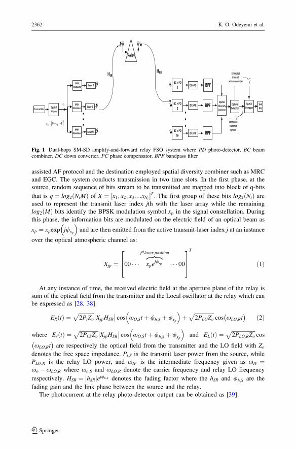
assisted AF protocol and the destination employed spatial diversity combiner such as MRC
and EGC. The system conducts transmission in two time slots. In the first phase, at the
source, random sequence of bits stream to be transmitted are mapped into block of q-bits
that is q ¼ log2 NtMð Þ of X ¼ x1; x2; x3. . .xNt½ �T . The first group of these bits log2 Ntð Þ are
used to represent the transmit laser index jth with the laser array while the remaining
log2 Mð Þ bits identify the BPSK modulation symbol xp in the signal constellation. During
this phase, the information bits are modulated on the electric field of an optical beam as
xp ¼ xpexp j/xp
� �and are then emitted from the active transmit-laser index j at an instance
over the optical atmospheric channel as:
Xjp ¼ 00 � � � xpej/xp
zfflffl}|fflffl{jthlaser position
� � � 00
264
375
T
ð1Þ
At any instance of time, the received electric field at the aperture plane of the relay is
sum of the optical field from the transmitter and the Local oscillator at the relay which can
be expressed as [28, 38]:
ER tð Þ ¼ffiffiffiffiffiffiffiffiffiffiffiffi2PtZo
pXjpHSR
�� �� cos xO;St þ /h;S þ /xp
� �þ
ffiffiffiffiffiffiffiffiffiffiffiffiffiffiffi2PLOZo
pcos xLO;Rt� �
ð2Þ
where Es tð Þ ¼ffiffiffiffiffiffiffiffiffiffiffiffiffiffi2Pt;SZo
pXjpHSR
�� �� cos xO;St þ /h;S þ /xp
� �and EL tð Þ ¼
ffiffiffiffiffiffiffiffiffiffiffiffiffiffiffiffiffiffi2PLO;RZo
pcos
xLO;Rt� �
are respectively the optical field from the transmitter and the LO field with Zodenotes the free space impedance. Pt;S is the transmit laser power from the source, while
PLO;R is the relay LO power, and xIF is the intermediate frequency given as xIF ¼xo � xLO;R where xo;S and xLO;R denote the carrier frequency and relay LO frequency
respectively. HSR ¼ hSRj jej/h;S denotes the fading factor where the hSR and /h;S are the
fading gain and the link phase between the source and the relay.
The photocurrent at the relay photo-detector output can be obtained as [39]:
Es�mated transmit
antenna number
Op�mal Detec�on
Spa�al Dempper
Sink Bits
l
Es�mated transmitsymbol
k
BC + PD 1
BC + PD Nr
BC + PD 2
Spa�al Diversity Combiner
DC+PC
DC+PC
DC+PC BPF
BPF
BPF
Source Bits Spa�al Mapper
, 0 0l k kx x 0 Tk
kx
Laser 1
Laser 2
Laser Nt
BPSK Modulator
BPSK Modulator
BPSK Modulator
Relay
HSRHRD
Fig. 1 Dual-hops SM-SD amplify-and-forward relay FSO system where PD photo-detector, BC beamcombiner, DC down converter, PC phase compensator, BPF bandpass filter
2362 K. O. Odeyemi et al.
123
iR tð Þ ¼ R
ZoES tð Þ þ EL tð Þ½ �2 ð3Þ
where R ¼ gqe= hvoð Þ is the responsivity of the photo-detector with electron charge
qe ¼ 1:6� 10�19C, and plank constant h ¼ 6:6� 10�34 Js, g denotes the photo-detector
efficiency and the optical central frequency vo ¼ xo=2p.
iR tð Þ ¼ RPt;S XjpHSR
�� ��2þRPL þ 2RffiffiffiffiffiffiffiffiffiffiffiffiffiffiffiPtPLO;R
pXjpHSR
�� �� cos xIF;Rt � /h;S � /xp
� �ð4Þ
where IDC;S ,RPt;S XjpHSR
�� ��2 and IDC;L ,RPL;R is the DC current generated due to signal
and LO electric field respectively. IAC , 2RffiffiffiffiffiffiffiffiffiffiffiffiffiffiffiPt;SPL;R
pXjpHSR
�� ��cos xIF;Rt � /h;S � /xp
� �is
the AC current which contains the useful information about the frequency and the phase of
the received signal at the relay. The total output DC current at the photo-detector can be
approximately equal to RPL;R [40]. Therefore, the short noise impaired during photo-
detection process at this stage is dominated by LO short noise with variance of
r2short;L;R ¼ 2qeRPLOBe, where Be is the electrical bandwidth of the photo-detector. In other
words, the instantaneous signal-to-noise ratio (SNR) of the optical receiver can be defined
as the time-average AC photocurrent and the total noise [40]. The SNR for the heterodyne
relay receiver can be expressed as:
SNR Hetð Þ;SR ¼i2AC tð Þ
2qeRPL;RBe
,RPt XjpHSR
�� ��2qeBe
ð5Þ
Based on the SNR Hetð Þ;SR, the sufficient statistics at the relay can be modeled as [28, 38]:
yR tð Þ ¼ffiffiffiffiffiffifficSR
pHSRXjp þ wR tð Þ ð6Þ
where cSR ¼ RPt= qeDfð Þ is the average received SNR at the relay system and wR tð Þ is thenoise term at the relay dominated by LO short noise model as Additive White Gaussian
Noise (AWGN) with zero-mean and r2short;L;R.During the second phase, the photocurrent iR tð Þ at the relay photo-detector output is
then amplified by the relay gain G, converted to optical signal and retransmitted to the
destination. At the destination, using the same approach at the relay, the received optical
signal at the nth heterodyne receiver at the destination can be expressed as:
ED;n tð Þ ¼ffiffiffiffiffiffiffiffiffiffiffiffiffiffiffi2Pt;RZo
pyR tð ÞGHRDj j cos xO;Rt þ /h;R
� �þ
ffiffiffiffiffiffiffiffiffiffiffi2PL;D
pcos xLO;Dt� �
ð7Þ
where Es tð Þ,ffiffiffiffiffiffiffiffiffiffiffiffi2PtZo
pyR tð ÞGHRDj jcos xLOt þ /h;R
� �and EL;D tð Þ,
ffiffiffiffiffiffiffiffiffiffiffiffiffiffiffiffi2PL;DZo
pcos xLO;Dt� �
are the signal electric field transmitted by relay and LO electric field at the destination
respectively. HRD , hRDj jej/h;R is the fading factor while the hRD and /h;R are the fading
gain and the link phase between the relay and the destination.
The photocurrent at the nth photo-detector at the destination can be similarly obtained
as:
Optical Spatial Modulation with Diversity Combiner in… 2363
123
iD;n tð Þ ¼ R
ZoEs tð Þ þ EL tð Þ½ �2
,RPt;R yR tð ÞGHRDj j2þRPL;RGHRD þ 2RffiffiffiffiffiffiffiffiffiffiffiffiffiffiffiffiPt;RPL;R
pyR tð ÞGHRDj j cos xIFt � /h;R
� �
ð8Þ
where IDC;s ,RPt;R yR tð ÞGHRDj j2 and IDC;L ,RPL;RGHRD is the DC current generated due
to signal and LO electric field respectively at the nth heterodyne receiver at the destination
while IAC;D , 2RffiffiffiffiffiffiffiffiffiffiffiffiffiPtPL;R
pyR tð ÞGHRDj jcos xIFt � /h;R
� �is the AC current which contains
the useful information about the frequency and the phase of the received signal at the
destination. The short noise impaired during photo-detection process at this stage is also
dominated by destination LO short noise with variance of r2short;L;D ¼ 2qeRPL;DBe. The
SNR on the R-to-D link for the nth heterodyne receiver can therefore be expressed as:
SNR Hetð Þ;RD ¼i2AC;n tð ÞD E
2qeRPL;DBe
,RPt yR tð ÞGHRDj j2
qeBe
ð9Þ
The received signal at the nth heterodyne receiver can be statistically obtained as:
yD tð Þ ¼ffiffiffiffiffiffifficRD
pGHRDyR tð Þ þ wD tð Þ,
ffiffiffiffiffiffifficRD
pGHRD
ffiffiffiffiffiffifficSR
pHSRXjp þ wR tð Þ
� �þ wD tð Þ
,
ffiffiffiffiffiffiffiffiffiffiffiffifficRDcSR
pGHRDHSRXjp|fflfflfflfflfflfflfflfflfflfflfflfflfflfflfflfflfflffl{zfflfflfflfflfflfflfflfflfflfflfflfflfflfflfflfflfflffl}
signal part
þffiffiffiffiffiffifficRD
pGHRDwR tð Þ þ wD tð Þ|fflfflfflfflfflfflfflfflfflfflfflfflfflfflfflfflfflfflfflfflfflffl{zfflfflfflfflfflfflfflfflfflfflfflfflfflfflfflfflfflfflfflfflfflffl}
Noise part
ð10Þ
In this paper, we assume that the receiver has full CSI and therefore after the nor-
malization of the noise, the received signal at the nth heterodyne receiver at the destination
can be further simplified as:
yD tð Þ ¼ffiffiffiffiK
pHRDXjp þ w tð Þ ð11Þ
where K ¼ G2H2RDcRDcSR
cRDG2H2RD
þ1with G denoting the amplification factor at the relay and w tð Þ is the
complex additive with Gaussian noise (AWGN) at the input of the destination having
similar statistical characteristic as wR tð Þ.At destination, we assume optimum detection (OD) to detect the transmitted SM signal
vector Xjp from the Source after the signal is combined by spatial diversity combiner.
When the OD is applied, the estimated laser index J and the transmitted constellation
symbol index p at a specific time instance can be expressed as [41]:
J; p� �
¼ argmaxJ;p
pY yD Xjp;HRD
��� �
, argminJ;p
ffiffiffiffiK
phDl xp 2
F� 2Re yHDhRDxp
� � ð12Þ
The equivalent end-to-end SNR, which is the instantaneous received SNR at the des-
tination, can be obtained as [19, 23, 42]:
ceq ¼c1c2
c1 þ c2,
X2i¼1
1
ci
!�1
; i 2 1; 2ð Þ ð13Þ
2364 K. O. Odeyemi et al.
123
where c1 and c2 are the instantaneous SNR at S-to-R and R-to-S links respectively which
are defined in Eqs. (5) and (9). It is assumed that both link has equal average SNR obtained
as c1 ¼ c2 ¼ RPt= qeDfð Þ. Thus, the upper bound for the end-to-end SNR ceq can be
derived by using the well-known inequality between geometric and harmonic means for
the random variable c1 and c2 which is given as [19, 23]:
ceq � ca ¼1
2
Y2i¼1
ci ð14Þ
3 Channel Statistical Model
The Gamma–Gamma was proposed by Andrew et al. for modeling FSO link with the
conditions from weak to strong turbulence. This model probability distribution function
(PDF) can be expressed as [43]:
fHmkhð Þ ¼ 2 abð Þ
aþb2
C að ÞC bð Þ haþb2 �1Ka�b 2
ffiffiffiffiffiffiffiffiabh
p� �; h[ 0 ð15Þ
where C :ð Þ and K :ð Þ are defined as gamma function and vth order modified Bessel function
of the 2nd kind respectively, a and b are the scintillation parameters which are specified as
[44]:
a ¼ exp0:49r2R
1þ 1:11r12=5R
� �5=6
0B@
1CA� 1
264
375�1
b ¼ exp0:51r2R
1þ 0:69r12=5R
� �5=6
0B@
1CA� 1
264
375�1
ð16Þ
where r2R ¼ 0:49C2n 2p=kð Þ7=6L11=6 is the Rytov Variation which is assumed to be spherical
wave with k stated as the optical wavelength, while L is the link range and C2n is the
refractive structure parameter that defines the turbulence strength [44].
Expressing Kv xð Þ in terms of Meijer-G function [45], Eq. (14)]:
Kv xð Þ ¼ 1
2G
2;00;2
x2
4
�;�v
2;�v
2
�����
!ð17Þ
So, we can express the PDF of the Gamma–Gamma channel define in (15) as:
fHmkhð Þ ¼ abð Þ
aþb2
C að ÞC bð Þ haþb2 �1G
2;00;2 abh
�;�a� b2
;b� a2
�����
!; h[ 0 ð18Þ
Also, the Gamma–Gamma channel PDF can be defined in terms of generalized power
series representation method of the modified Bessel function of the second kind as [44, 46]:
Optical Spatial Modulation with Diversity Combiner in… 2365
123
Kv xð Þ ¼ p2 sin pvð Þ
X1l¼0
1
C l� vþ 1ð Þl!x
2
� �2l�v
� 1
C lþ vþ 1ð Þl!x
2
� �2lþv� �
ð19Þ
where v 62 Z and xj j\1Thus, the PDF in (5) can also be expressed as:
fHmkhð Þ ¼
X1l¼0
ak a; bð Þhkþb�1 þ ak b; að Þhkþa�1� �
ð20Þ
where
ak x; yð Þ ¼ p xyð Þlþb
sin p x� yð Þð ÞC xð ÞC yð ÞC k � xþ yð Þk!
The misalignment fading due to pointing error hp� �
loss by considering the detector
size, beam width, and jitter variance is modeled by Raleigh distribution given as [47, 48]:
fHmkhp� �
¼ n2
An2o
hpn2 � 1; 0� hp �Ao ð21Þ
where n ¼ we=2rs and we is the equivalent beam width at the receiving end, rs is the
standard deviation of the pointing error displacement at the receiver, is given as Ao ¼erf 2 vð Þ; v ¼
ffiffiffiffiffiffiffiffip=2
pra=wLð Þ where ra denotes the radius of the receiver aperture and wL is
the beam waist radius at distance L. Considering the impact of pointing error impairment,
the PDF of the combined channel can be expressed as [49]:
fHmkhð Þ ¼ abn2
AoC að ÞC bð ÞG3;01;3
abAo
hn2
n2 � 1; a� 1; b� 1
����� �
ð22Þ
The PDF of ci is obtained by power transformation of (22) and is expressed as:
fci cið Þ ¼ n2i2ciC aið ÞC bið ÞG
3;01;3 aibi
ffiffiffifficici
rn2i þ 1
n2i ; ai; bi
����� �
ð23Þ
4 Statistical Characteristics of End-to-End SNR
4.1 Under the Influence of Atmospheric Turbulence Without Pointing Error
In this section, we derive the MGF, PDF and CDF of the end-to-end SNR ca defined in
(14), with the assumption that the channel is independent non-identical distribution
Gamma–Gamma turbulence channel.
4.1.1 MGF of the End-to-End SNR ca
The MGF of the end-to-end SNR ca can be derived in closed form as:
2366 K. O. Odeyemi et al.
123

Mca �Sð Þ ¼Z1
0
Z1
0
exp� SY2i¼1
c1=2i
!" # Y2i¼1
fci cið Þ" #
dci
,
Z1
0
Z1
0
exp �Sc12
1c12
2
� �fc1 c1ð Þfc2 c2ð Þdc1dc2
ð24Þ
It should be noted that we can use the Gamma–Gamma PDF define in (18) and (20) to
evaluate the MGF defined in (24). However, the integrals of the equation will yield infinite
result and will be untraceable if we apply (20) to compute these integrals. Therefore we
cannot obtain the exact close form expression for the end-to-end SNR. As a result of this,
we thus applied the defined PDF in (18) to determine the MGF as follows:
If the PDF in terms of end-to-end SNR for the Gamma–Gamma can be expressed as:
fci cið Þ ¼ aibið Þaiþbi
2 caiþbi
4�1
i
2C aið ÞC bið Þcaiþbi
4
i
G2;00;2
abffiffiffiffi�ci
p ffiffiffiffici
p �;�ai � bi
2;bi � ai
2
�����
!ð25Þ
If we let the Ni ¼ abffiffiffici
p and apply the Meijer-G identity defined in [50], Eq. (9.31.5)],
then the PDF can be expressed as:
fci cið Þ ¼Ni
ffiffiffiffici
p� �aiþbi2
2C aið ÞC bið Þ c�1i G
2;00;2 Ni
ffiffiffiffici
p j�;�
ai � bi2
;bi � ai
2
0@
1A
,1
2C aið ÞC bið Þ c�1i G
2;00;2 Ni
ffiffiffiffici
p �;�ai2;bi2
������
0@
1A
ð26Þ
The first integration in (24) on c1 is of the form:
T1 Sð Þ ¼ 1
2C a1ð ÞC b1ð Þ
Z1
0
c�11 G
2;00;2 N1
ffiffiffiffiffic1
p �;�a12;b12
�����
!exp �SVc1=21
� �dc1 ð27Þ
where V ¼ffiffiffic2
p
2
Using the Meijer-G identity of the exponential function in [45], Eq. (11)] to (27), then,
T1 Sð Þ ¼ 1
2C a1ð ÞC b1ð Þ
Z1
0
c�11 G
2;00;2 N1
ffiffiffiffiffic1
p �;�a12;b12
�����
!G
1;00;1 SVc1=21 0
��� �dc1 ð28Þ
let Z ¼ c1=21 ; Z2 ¼ c1;dc1dZ
¼ 2Z and dc1 ¼ 2ZdZ, then apply the Meijer-G identity in [45],
Eq. (21)]
T1 Sð Þ ¼ 1
C a1ð ÞC b1ð ÞG1;22;1
SV
N1
1� a1; 1� b10
����� �
ð29Þ
Using the similar method, the integration on c2 can be obtained by substituting (29) for
(24):
Optical Spatial Modulation with Diversity Combiner in… 2367
123

T2 Sð Þ ¼ 1
C a1ð ÞC b1ð Þ1
2C a2ð ÞC b2ð Þ
Z1
0
c�11 G
2;00;2 N2
ffiffiffiffiffic2
p �;�a22;b22
������
0@
1AG
1;22;1
SV
N1
ffiffiffiffiffic2
p 1� a1; 1� b10
����� �
dc1
,1
C a1ð ÞC b1ð Þ1
C a2ð ÞC b2ð ÞG1;44;1
SV
N1N2
1� a1; 1� b1; 1� a2; 1� b20
����� �
ð30Þ
Thus, substitute (29) and (30) for (24), then the MGF can be obtained as:
Mcb Sð Þ ¼Y2i¼1
1
C aið ÞC bið ÞG1;44;1
S
2N1N2
1� a1; 1� b1; 1� a2; 1� b20
����� �
ð31Þ
4.1.2 PDF of End-to-End SNR ca
The PDF of cb can be determined by applying the inversed Laplace Transform L�1 to the
MGF in (31) and this can be expressed as fca cð Þ ¼ L�1 Mca Sð Þ; c� �
. Applying the identity
[51], Eq. (3.40.1.1)] for the inverse Laplace transform of the Meijer-G function, we
obtained the PDF of cb in closed form as:
fca cð Þ ¼ c�1Y2i¼1
1
C aið ÞC bið ÞG1;44;1 2c
Y2i¼1
Ni�
a1; b1; a2; b2
���� !
ð32Þ
4.1.3 CDF of End-to-End SNR ca
The CDF of the ca can be defined as Fca cð Þ ¼Rc0
fca cð Þdc. Applying the integral identity
stated in [45], Eq. (26)], the CDF can therefore be obtained as follows:
Fcb cð Þ ¼Y2i¼1
1
C aið ÞC bið Þ
Zc
0
c�1Y2i¼1
1
C aið ÞC bið ÞG1;44;1 2c
Y2i¼1
Ni
�a1; b1; a2; b2
���� !
,
Y2i¼1
1
C aið ÞC bið ÞG4;11;5 2c
Y2i¼1
Ni
1
a1; b1; a2; b2; 0
���� ! ð33Þ
4.2 Under the Influence of Atmospheric Turbulence and Pointing Error
4.2.1 MGF of End-to-End SNR ca for the Pointing Error
Following the same approach used in obtaining the MGG of end-to-end SNR without
pointing error, the MGF of end-to-end SNR with pointing error can thus be obtained by
using (24), and the first integral on c1 is expressed as:
T1 Sð Þ ¼Z1
0
c�11 G
3;01;3 a1b1
ffiffiffiffiffic1c1
rn21 þ 1
n21; a1; b1
����� �
G1;00;1 SVc1=21
�0
����� �
dc1 ð34Þ
2368 K. O. Odeyemi et al.
123

By expressing the exponential function in form of Meijer-G function [50], Eq. (8.2.2)]
and the integration of T1 Sð Þ can be solved using [45], Eq. (21)] as:
T1 Sð Þ ¼ 2G3;12;3
a1b1SV
ffiffiffiffiffic1
p 1; n21 þ 1
n21; a1; b1
����� �
ð35Þ
To solve the second integral in (24), substitute for T1 Sð Þ and apply the Meijer-G
identity given in [50], Eq. (8.2.2)] and [45], Eq. (21)], then the MGF is therefore obtained
as:
Mca Sð Þ ¼Y2i¼1
n2iC aið ÞC bið Þ
� �G
6;13;6
2
S
Y2i¼1
Ni1;w3
w1;w2
���� !
ð36Þ
where w1 ¼ a1; b1a2; b2, w2 ¼ n21; n22 and w3 ¼ n21 þ 1; n22 þ 1
4.2.2 PDF of End-to-End SNR ca for the Pointing Error
To determine the PDF of the end-to-end SNR,fca cð Þ, apply inverse Laplace transform to
(36) using the identity given in [51], Eq. (30.40.1.1)] as:
fca cð Þ ¼ c�1Y2i¼1
n2iC aið ÞC bið Þ
� �G
6;13;6 2c
Y2i¼1
Niw3
w1;w2
���� !
ð37Þ
4.2.3 CDF of End-to-End SNR ca for the Pointing Error
The CDF for the end-to-end SNR can be obtained as Fca cð Þ ¼Rc0
fca cð Þdc. Applying the
integral identity stated in [45], Eq. (26)], the CDF can therefore be obtained as follows:
Fca cð Þ ¼Zc
0
c�1Y2i¼1
n2iC aið ÞC bið Þ
� �G
6;02;6 2c
Y2i¼1
Ni
w3
w1;w2
���� !
dc
,
Y2i¼1
n2iC aið ÞC bið Þ
� �G
6;13;6 2c
Y2i¼1
Ni
1;w3
w1;w2
���� ! ð38Þ
5 Performance Analysis
At the destination, the receiver combines transmit amplified SM signal from the relay
through the use of MRC and EGC. Thus, to determine the ABER for the proposed SM-SD
dual-hop AF relay system, a well-known boundary technique is adopted to evaluate the
BER under the fading condition. The average BER can be bounded as given in [41] by:
ABERSM�SD � NtMð Þ�1
log2 NtMð ÞXNt
j¼1
XMp¼1
XNt
J¼jþ1
XMp¼pþ1
N p; pð ÞAPEP xj;p ! xJ;p
� �ð39Þ
Optical Spatial Modulation with Diversity Combiner in… 2369
123

where N p; pð Þ is the number of bit error when selecting p instead of p as the transmit unit
index, APEP xj;p ! xJ;p
� �dotes the Average Pairwise Error Probability (APEP) of
deciding on the constellation vector xj;p given that xJ;p is transmitted.
5.1 Average Pairwise Error Probability for MRC Combiner
The instantaneous SNR at the output of MRC is defined as [52]:
cMRCt ¼
XNDr
n¼1
can ð40Þ
where can is the end-to-end SNR received at the nth heterodyne receiver. Thus, the PEP can
be expressed as:
PEPMRC xj;p ! xJ;p
� �¼ Q
ffiffiffiffiffiffiffiffiffiffiffiffi2cMRC
t
q� �
,Q
ffiffiffiffiffiffiffiffiffiffiffiffiffiffiffiffiffi2XND
r
n¼1
can
vuut0B@
1CA
ð41Þ
Thus, by averaging (41), the average PEP for the MRC can be obtained as:
APEPMRC xj;p ! xJ;p
� �¼Z1
0
ffiffiffiffiffiffiffiffiffiffiffiffiffiffiffiffiffi2XND
r
n¼1
can
vuut0B@
1CAfca cð Þdc ð42Þ
Using the upper bound of Crag’s Q-function defined as Q xð Þ� 1=2 exp �x2=2ð Þ [53],
then the average PEP can be expressed as:
APEPMRC xj;p ! xJ;p
� �¼ 1
2
Z1
0
exp �XND
r
n¼1
can
!fca cð Þdc
,1
2
YNDr
n¼1
McanSð Þ
ð43Þ
To determine the average PEP for the MRC-SM under the influence of atmospheric
turbulence without pointing error, substitute (31) for (43) as:
APEPMRC xj;p ! xJ;p
� �¼ 1
2
Y2i¼1
1
C aið ÞC bið ÞG1;44;1
1
2N1N2
1� a1;1�b1;1� a2;1�b20
����� �" #ND
r
ð44Þ
Similarly, the average PEP for the MRC-SM under the influence of atmospheric tur-
bulence with pointing error, substitute (36) for (43) as:
2370 K. O. Odeyemi et al.
123

APEPMRC xj;p ! xJ;p
� �¼ 1
2
Y2i¼1
n2iC aið ÞC bið Þ
� �G
6;13;6 2
Y2i¼1
Ni1;w3
w1;w2
���� !" #ND
r
ð45Þ
Thus, the average BER for the MRC dual-hop relay system without and with pointing
error can therefore be respectively obtained by substituting (44) and (45) for (39):
ABERMRC without pointing errorð Þ �NtMð Þ�1
2 log2 NtMð ÞXNt
j¼1
XMp¼1
XNt
J¼jþ1
XMp¼pþ1
N p; pð Þ
Y2i¼1
1
C aið ÞC bið ÞG1;44;1
1
2N1N2
1� a1; 1� b1; 1� a2; 1� b20
����� �" #ND
r
ð46Þ
ABERMRC with pointing errorð Þ �NtMð Þ�1
2 log2 NtMð ÞXNt
j¼1
XMp¼1
XNt
J¼jþ1
XMp¼pþ1
N p; pð Þ
Y2i¼1
n2iC aið ÞC bið Þ
� �G
6;13;6 2
Y2i¼1
Ni
1;w3
w1;w2
���� !" #ND
r
ð47Þ
5.2 Average Pairwise Error Probability for EGC Combiner
The instantaneous SNR at the output of MRC is defined as [52]:
cEGCt ¼ 1
NDr
XNDr
n¼1
ffiffiffiffiffiffican
p !2
ð48Þ
The approach detailed in [54, 55], cT ¼PND
r
n¼1
ffiffiffiffiffiffican
p !2
with cT ¼ NDr c,acT ¼ ND
r aþ ec,
bcT ¼ NDr b; denoting the adjustment parameter in order to improve the accuracy of pro-
posed approximation [55] is defined as:
ec ¼1
NDr
� 1
� ��0:127� 0:95a� 0:0058b
1þ 0:00124aþ 0:98bð49Þ
The average PEP for the EGC can be expressed as:
APEPEGC xj;p ! xJ;p
� �¼Z1
0
ffiffiffiffiffiffiffiffiffiffiffiffi2cEGCt
q� �fca cð Þdc
,�Z1
0
Q=ffiffiffiffiffiffiffiffiffiffiffiffi2cEGCt
q� �Fca cð Þdc
ð50Þ
where Q= :ð Þ is the derivative of Q-function which is defined in [57] as
Q= xð Þ ¼ 12ffiffip
p exp �x2=2ð Þ
Optical Spatial Modulation with Diversity Combiner in… 2371
123
APEPEGC xj;p ! xJ;p
� �¼ 1
2ffiffiffip
pZ1
0
1ffiffiffiffifficT
p exp � cTNDr
� �Fca cTð ÞdcT ð51Þ
To determine the APER for the EGC dual-hop AF system under the influence of
atmospheric turbulence without pointing error, substitute the CDF defined in (33) for (50)
APEPEGC xj;p ! xJ;p
� �,
1
2ffiffiffip
pY2i¼1
1
C acTi� �
C bcTi� �
" # Z1
0
c�1=2T exp � cT
NDr
� �G
1;44;1
� 2cTY2i¼1
Ni1
acT1 ; bcT1 ; acT2 ; bcT2 ; 0
���� !
dcT ð52Þ
Applying the integral indent defined in [50], Eq. (7.813.1)], the APER for the EGC
dual-hop AF system under the influence of atmospheric turbulence without pointing error
can be expressed as:
APEPEGC xj;p!xJ;p
� �,1
2
ffiffiffiffiffiffiffiNDr
p
r Y2i¼1
1
C acTi� �
C bcTi� �
" #G
4;22;5 2ND
r
Y2i¼1
Ni
1
2;1
acT1 ;bcT1 ;acT2 ;bcT2 ;0
�����
!
ð53Þ
Under the influence of pointing error, using (38) in (51), the average PEP can be
expressed as:
APEPEGC xj;p ! xJ;p
� �¼ 1
2ffiffiffip
pY2i¼1
n2iC acTi� �
C bcTi� �
" # Z1
0
c�1=2T exp � cT
NDr
� �G
6;13;6
� 2cTY2i¼1
Ni1;w3
w1;w2
���� !
dcT ð54Þ
Applying the integral indent defined in [50], Eq. (7.813.1)], the APER for the EGC
dual-hop AF system under the influence of atmospheric turbulence without pointing error
can be expressed as:
APEPEGC xj;p ! xJ;p
� �¼ 1
2
ffiffiffiffiffiffiffiNDr
p
r Y2i¼1
n2iC acTi� �
C bcTi� �
" #G
6;24;6 2ND
r
Y2i¼1
Ni
1
2; 1;w3
w1;w2
�����
!ð55Þ
Thus, the average BER for the MRC dual hop relay system can therefore be obtained by
substituting (53) and (55) for (39):
ABEREGC withpointingerrorð Þ�NtMð Þ�1
2log2 NtMð Þ
ffiffiffiffiffiffiffiNDr
p
r Y2i¼1
n2iC acTi� �
C bcTi� �
" #XNt
j¼1
XMp¼1
XNt
J¼jþ1
XMp¼pþ1
N p;pð Þ
�G4;22;5 2ND
r
Y2i¼1
Ni
1
2;1
acT1 ;bcT1 ;acT2 ;bcT2 ;0
������
0@
1A
ð56Þ
2372 K. O. Odeyemi et al.
123
ABEREGC with pointing errorð Þ �NtMð Þ�1
2 log2 NtMð Þ
ffiffiffiffiffiffiffiNDr
p
r Y2i¼1
n2iC acTi� �
C bcTi� �
" #XNt
j¼1
XMp¼1
XNt
J¼jþ1
XMp¼pþ1
N p; pð ÞG6;24;6
� 2NDr
Y2i¼1
Ni
1
2; 1;w3
w1;w2
������
0@
1A
ð57Þ5.3 Effective Capacity for the Systems
The capacity of spatial modulation systems as stated in [56–59] cannot be determined in
the same way it is done in MIMO communication systems. This is because, the number of
transmit antenna represents the added information, and antenna index signifies the spatial
constellation not as the information source as in other MIMO systems. Therefore, using the
convectional approach stated in [59], the capacity for the dual-hap spatial modulation with
combiner can be expressed as:
CSM ¼ log2 Nst M
� �1þ Pe log2 Peð Þ þ Pc log2 Pcð Þ½ � ð58Þ
where, Pe is the overall probability of error defined in Eq. (39), and Pc ¼ 1� Pe represents
the probability of correct detection and log2 Nst M
� �defines the total bits convey by the
system.
6 Numerical Results and Discussions
In this section, using the derived expression of Eqs. (46), (47), (56), (57) and (58), we
present the effect of atmospheric turbulence and pointing error on the average BER and the
effective capacity performance of optical SM-SD dual-hops CSI-assisted relay. Generally,
we assume that the link between the S-R and R-D are symmetric atmospheric turbulence
channel with weak a ¼ 3:78; b ¼ 3:74ð Þ, moderate a ¼ 2:50; b ¼ 2:06ð Þ and strong
a ¼ 2:04; b ¼ 1:10ð Þ.
5 10 15 20 25 30 3510
-10
10-8
10-6
10-4
10-2
100
Average SNR (dB)
AB
ER
MRC (Nr=2)MRC (Nr=4)
α= 3.78β =3.74
α= 2.50β =2.06
α= 2.04β =1.10
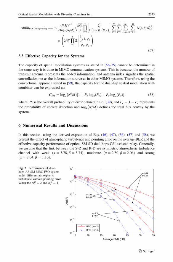
Fig. 2 Performance of dual-hops AF SM-MRC-FSO systemunder different atmosphericturbulence without pointing error
When the NDr ¼ 2 and ND
r ¼ 4
Optical Spatial Modulation with Diversity Combiner in… 2373
123
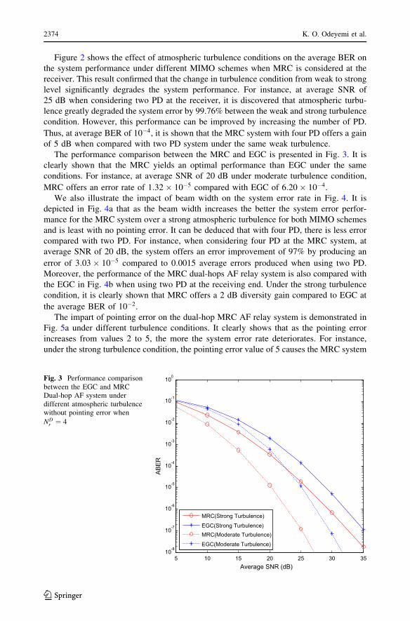
Figure 2 shows the effect of atmospheric turbulence conditions on the average BER on
the system performance under different MIMO schemes when MRC is considered at the
receiver. This result confirmed that the change in turbulence condition from weak to strong
level significantly degrades the system performance. For instance, at average SNR of
25 dB when considering two PD at the receiver, it is discovered that atmospheric turbu-
lence greatly degraded the system error by 99.76% between the weak and strong turbulence
condition. However, this performance can be improved by increasing the number of PD.
Thus, at average BER of 10�4, it is shown that the MRC system with four PD offers a gain
of 5 dB when compared with two PD system under the same weak turbulence.
The performance comparison between the MRC and EGC is presented in Fig. 3. It is
clearly shown that the MRC yields an optimal performance than EGC under the same
conditions. For instance, at average SNR of 20 dB under moderate turbulence condition,
MRC offers an error rate of 1:32� 10�5 compared with EGC of 6:20� 10�4.
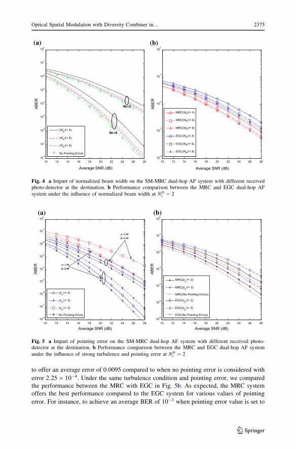
We also illustrate the impact of beam width on the system error rate in Fig. 4. It is
depicted in Fig. 4a that as the beam width increases the better the system error perfor-
mance for the MRC system over a strong atmospheric turbulence for both MIMO schemes
and is least with no pointing error. It can be deduced that with four PD, there is less error
compared with two PD. For instance, when considering four PD at the MRC system, at
average SNR of 20 dB, the system offers an error improvement of 97% by producing an
error of 3:03� 10�5 compared to 0:0015 average errors produced when using two PD.
Moreover, the performance of the MRC dual-hops AF relay system is also compared with
the EGC in Fig. 4b when using two PD at the receiving end. Under the strong turbulence
condition, it is clearly shown that MRC offers a 2 dB diversity gain compared to EGC at
the average BER of 10�2.
The impart of pointing error on the dual-hop MRC AF relay system is demonstrated in
Fig. 5a under different turbulence conditions. It clearly shows that as the pointing error
increases from values 2 to 5, the more the system error rate deteriorates. For instance,
under the strong turbulence condition, the pointing error value of 5 causes the MRC system
5 10 15 20 25 30 3510-8
10-7
10-6
10-5
10-4
10-3
10-2
10-1
100
Average SNR (dB)
AB
ER
MRC(Strong Turbulence)
EGC(Strong Turbulence)MRC(Moderate Turbulence)
EGC(Moderate Turbulence)
Fig. 3 Performance comparisonbetween the EGC and MRCDual-hop AF system underdifferent atmospheric turbulencewithout pointing error when
NDr ¼ 4
2374 K. O. Odeyemi et al.
123
to offer an average error of 0:0095 compared to when no pointing error is considered with
error 2:25� 10�4. Under the same turbulence condition and pointing error, we compared
the performance between the MRC with EGC in Fig. 5b. As expected, the MRC system
offers the best performance compared to the EGC system for various values of pointing
error. For instance, to achieve an average BER of 10�3 when pointing error value is set to
10 12 14 16 18 20 22 24 26 2810-8
10-7
10-6
10-5
10-4
10-3
10-2
10-1
100
Average SNR (dB)
AB
ER
(We/r= 4)
(We/r= 6)
(We/r= 8)
No Pointing Errors
Nr=2
Nr=4
10 12 14 16 18 20 22 24 26 2810
-4
10-3
10-2
10-1
100
Average SNR (dB)
AB
ER
MRC(We/r= 4)
MRC(We/r= 6)
MRC(We/r= 8)
EGC(We/r= 4)
EGC(We/r= 6)
EGC(We/r= 8)
(a) (b)
Fig. 4 a Impart of normalized beam width on the SM-MRC dual-hop AF system with different receivedphoto-detector at the destination. b Performance comparison between the MRC and EGC dual-hop AF
system under the influence of normalized beam width at NDr ¼ 2
10 12 14 16 18 20 22 24 26 2810-6
10-5
10-4
10-3
10-2
10-1
100
Average SNR (dB)
AB
ER
MRC( s/r= 2)
MRC( s/r= 3)
MRC(No Pointing Errors)
EGC( s/r= 2)
EGC( s/r= 3)
EGC(No Pointing Errors)
10 12 14 16 18 20 22 24 26 2810-8
10-7
10-6
10-5
10-4
10-3
10-2
10-1
100
Average SNR (dB)
AB
ER
( s /r= 2)
( s /r= 3)
( s /r= 5)
No Pointing Errors
α= 2.04β =1.10
α= 2.50β =2.06
(a) (b)
Fig. 5 a Impart of pointing error on the SM-MRC dual-hop AF system with different received photo-detector at the destination. b Performance comparison between the MRC and EGC dual-hop AF system
under the influence of strong turbulence and pointing error at NDr ¼ 2
Optical Spatial Modulation with Diversity Combiner in… 2375
123
2, the MRC system requires only a power of 21 dB compare with EGC of 24 dB when the
receiver is equipped with two PD.
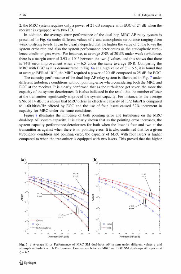
In addition, the average error performance of the dual-hop MRC AF relay system is
presented in Fig. 6a under different values of n and atmospheric turbulence ranging from
weak to strong levels. It can be clearly depicted that the higher the value of n, the lower thesystem error rate and also the system performance deteriorates as the atmospheric turbu-
lence condition gets worst. For instance, at average SNR of 20 dB under weak turbulence,
there is a margin error of 3:93� 10�4 between the two n values, and this shows that there
is 74% error improvement when n ¼ 6:5 under the same average SNR. Comparing the
MRC with EGC as it is demonstrated in Fig. 6a at a high value of n ¼ 6:5, it is found that
at average BER of 10-3, the MRC required a power of 20 dB compared to 25 dB for EGC.
The capacity performance of the dual-hop AF relay system is illustrated in Fig. 7 under
different turbulence conditions without pointing error when considering both the MRC and
EGC at the receiver. It is clearly confirmed that as the turbulence get sever, the more the
capacity of the system deteriorates. It is also indicated in the result that the number of laser
at the transmitter significantly improved the system capacity. For instance, at the average
SNR of 14 dB, it is shown that MRC offers an effective capacity of 1.72 bit/s/Hz compared
to 1.60 bits/s/Hz offered by EGC and the use of four lasers caused 32% increment in
capacity for MRC under the same conditions.
Figure 8 illustrates the influence of both pointing error and turbulence on the MRC
dual-hop AF system capacity. It is clearly shown that as the pointing error increases, the
system capacity performance deteriorates for both when the laser is four and two at the
transmitter as against when there is no pointing error. It is also confirmed that for a given
turbulence condition and pointing error, the capacity of MRC with four lasers is higher
compared to when the transmitter is equipped with two lasers. This proved that the higher
10 12 14 16 18 20 22 24 26 2810
-7
10-6
10-5
10-4
10-3
10-2
10-1
100
Average SNR (dB)
AB
ER
( = 6.5)
( = 2)
No Pointing Errors
α= 2.04
β =1.10
α= 2.50
β =2.06
α= 3.78
β =3.74
10 12 14 16 18 20 22 24 26 2810
-6
10-5
10-4
10-3
10-2
10-1
100
Average SNR (dB)
AB
ER
MRC
EGC
α= 2.04
β =1.10
α= 2.50
β =2.06
(a) (b)
Fig. 6 a Average Error Performance of MRC SM dual-hops AF system under different values n andatmospheric turbulence. b Performance Comparison between MRC and EGC SM dual-hops AF system atn ¼ 6:5
2376 K. O. Odeyemi et al.
123
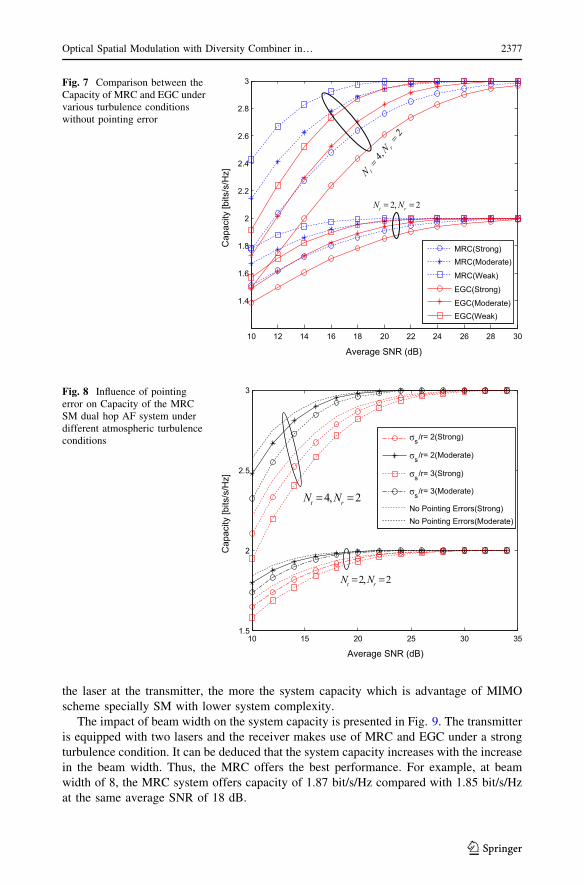
the laser at the transmitter, the more the system capacity which is advantage of MIMO
scheme specially SM with lower system complexity.
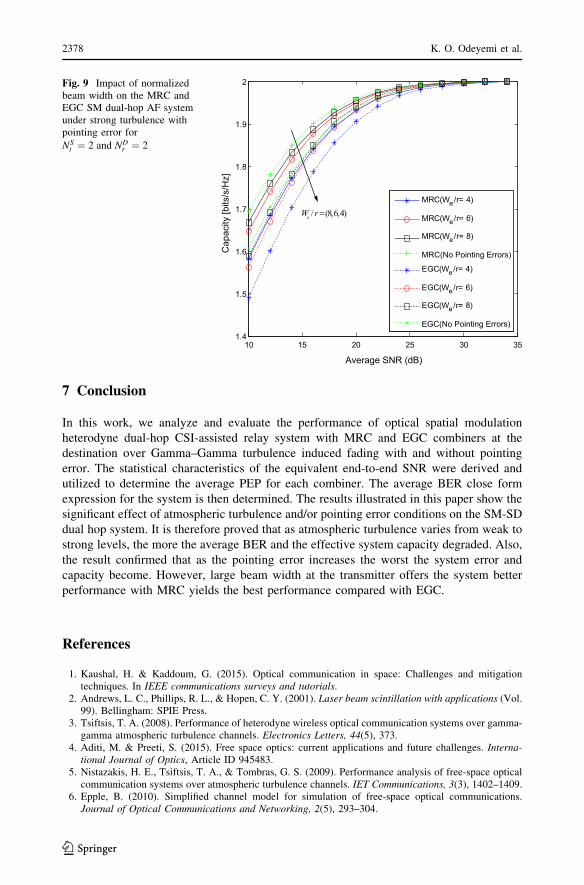
The impact of beam width on the system capacity is presented in Fig. 9. The transmitter
is equipped with two lasers and the receiver makes use of MRC and EGC under a strong
turbulence condition. It can be deduced that the system capacity increases with the increase
in the beam width. Thus, the MRC offers the best performance. For example, at beam
width of 8, the MRC system offers capacity of 1.87 bit/s/Hz compared with 1.85 bit/s/Hz
at the same average SNR of 18 dB.
10 12 14 16 18 20 22 24 26 28 30
1.4
1.6
1.8
2
2.2
2.4
2.6
2.8
3
Average SNR (dB)
Cap
acity
[bits
/s/H
z]
MRC(Strong)MRC(Moderate)
MRC(Weak)
EGC(Strong)
EGC(Moderate)EGC(Weak)
4,
2
t
r
N
N
2, 2t rN N
Fig. 7 Comparison between theCapacity of MRC and EGC undervarious turbulence conditionswithout pointing error
10 15 20 25 30 351.5
2
2.5
3
Average SNR (dB)
Cap
acity
[bits
/s/H
z]
s /r= 2(Strong)
s/r= 2(Moderate)
s/r= 3(Strong)
s/r= 3(Moderate)
No Pointing Errors(Strong)No Pointing Errors(Moderate)
4, 2t rN N
2, 2t rN N
Fig. 8 Influence of pointingerror on Capacity of the MRCSM dual hop AF system underdifferent atmospheric turbulenceconditions
Optical Spatial Modulation with Diversity Combiner in… 2377
123
7 Conclusion
In this work, we analyze and evaluate the performance of optical spatial modulation
heterodyne dual-hop CSI-assisted relay system with MRC and EGC combiners at the
destination over Gamma–Gamma turbulence induced fading with and without pointing
error. The statistical characteristics of the equivalent end-to-end SNR were derived and
utilized to determine the average PEP for each combiner. The average BER close form
expression for the system is then determined. The results illustrated in this paper show the
significant effect of atmospheric turbulence and/or pointing error conditions on the SM-SD
dual hop system. It is therefore proved that as atmospheric turbulence varies from weak to
strong levels, the more the average BER and the effective system capacity degraded. Also,
the result confirmed that as the pointing error increases the worst the system error and
capacity become. However, large beam width at the transmitter offers the system better
performance with MRC yields the best performance compared with EGC.
References
1. Kaushal, H. & Kaddoum, G. (2015). Optical communication in space: Challenges and mitigationtechniques. In IEEE communications surveys and tutorials.
2. Andrews, L. C., Phillips, R. L., & Hopen, C. Y. (2001). Laser beam scintillation with applications (Vol.99). Bellingham: SPIE Press.
3. Tsiftsis, T. A. (2008). Performance of heterodyne wireless optical communication systems over gamma-gamma atmospheric turbulence channels. Electronics Letters, 44(5), 373.
4. Aditi, M. & Preeti, S. (2015). Free space optics: current applications and future challenges. Interna-tional Journal of Optics, Article ID 945483.
5. Nistazakis, H. E., Tsiftsis, T. A., & Tombras, G. S. (2009). Performance analysis of free-space opticalcommunication systems over atmospheric turbulence channels. IET Communications, 3(3), 1402–1409.
6. Epple, B. (2010). Simplified channel model for simulation of free-space optical communications.Journal of Optical Communications and Networking, 2(5), 293–304.
10 15 20 25 30 351.4
1.5
1.6
1.7
1.8
1.9
2
Average SNR (dB)
Cap
acity
[bits
/s/H
z]
MRC(We/r= 4)
MRC(We/r= 6)
MRC(We/r= 8)
MRC(No Pointing Errors)
EGC(We/r= 4)
EGC(We/r= 6)
EGC(We/r= 8)
EGC(No Pointing Errors)
/ (8,6,4)eW r
Fig. 9 Impact of normalizedbeam width on the MRC andEGC SM dual-hop AF systemunder strong turbulence withpointing error for
NSt ¼ 2 and ND
r ¼ 2
2378 K. O. Odeyemi et al.
123
7. Popoola, W. O., Ghassemlooy, Z., & Ahmadi, V. (2008). Performance of sub-carrier modulated free-space optical communication link in negative exponential atmospheric turbulence environment. Inter-national Journal of Autonomous and Adaptive Communications Systems, 1(3), 342–355.
8. Al-Habash, M. A., Andrews, L. C., & Phillips, R. L. (2001). Mathematical model for the irradianceprobability density function of a laser beam propagating through turbulent media. Optical Engineering,40(8), 1554–1562.
9. Trung, H. D., & Pham, A. T. (2014). Pointing error effects on performance of free-space opticalcommunication systems using SC-QAM signals over atmospheric turbulence channels. AEU-Interna-tional Journal of Electronics and Communications, 68(9), 869–876.
10. Garcıa-Zambrana, A., Castillo-Vazquez, B., & Castillo-Vazquez, C. (2012). Asymptotic error-rateanalysis of FSO links using transmit laser selection over gamma-gamma atmospheric turbulencechannels with pointing errors. Optics Express, 20(3), 2096–2109.
11. Lee, I. E., Ghassemlooy, Z. & Ng, W. P. (2012). Effects of aperture averaging and beam width onGaussian free space optical links in the presence of atmospheric turbulence and pointing error. In 201214th International conference on transparent optical networks (ICTON) (pp. 1–4). IEEE.
12. Krishnan, P., & Kumar, D. S. (2014). Bit error rate analysis of free-space optical system with spatialdiversity over strong atmospheric turbulence channel with pointing errors. Optical Engineering, 53(12),126108.
13. Sandalidis, H. G., Tsiftsis, T. A., & Karagiannidis, G. K. (2009). Optical wireless communications withheterodyne detection over turbulence channels with pointing errors. Journal of Lightwave Technology,27(20), 4440–4445.
14. Datsikas, C. K., Peppas, K. P., Sagias, N. C., & Tombras, G. S. (2010). Serial free-space optical relayingcommunications over gamma-gamma atmospheric turbulence channels. Journal of Optical Communi-cations and Networking, 2(8), 576–586.
15. Acampora, A. S., & Krishnamurthy, S. V. (1999). A broadband wireless access network based on mesh-connected free-space optical links. IEEE Personal Communications, 6(5), 62–65.
16. Akella, J., Yuksel, M. & Kalyanaraman, S. (2005). Error analysis of multi-hop free-space opticalcommunication. In IEEE international conference on communications. ICC 2005 (Vol. 3,pp. 1777–1781) IEEE.
17. Tsiftsis, T. A., Sandalidis, H. G., Karagiannidis, G. K. & Sagias, N. C. (2006). Multihop free-spaceoptical communications over strong turbulence channels. In 2006 IEEE international conference oncommunications (Vol. 6, pp. 2755–2759). IEEE.
18. Anees, S., & Bhatnagar, M. R. (2015). Performance evaluation of decode-and-forward dual-hopasymmetric radio frequency-free space optical communication system. IET Optoelectronics, 9(5),232–240.
19. Tang, X., Wang, Z., Xu, Z., & Ghassemlooy, Z. (2014). Multihop free-space optical communicationsover turbulence channels with pointing errors using heterodyne detection. Journal of LightwaveTechnology, 32(15), 2597–2604.
20. Kazemlou, S., Hranilovic, S., & Kumar, S. (2011). All-optical multihop free-space optical communi-cation systems. Journal of Lightwave Technology, 29(18), 2663–2669.
21. Peppas, K. P., Stassinakis, A. N., Nistazakis, H. E., & Tombras, G. S. (2013). Capacity analysis of dualamplify-and-forward relayed free-space optical communication systems over turbulence channels withpointing errors. Journal of Optical Communications and Networking, 5(9), 1032–1042.
22. Popoola, W. O., & Ghassemlooy, Z. (2009). BPSK subcarrier intensity modulated free-space opticalcommunications in atmospheric turbulence. Journal of Lightwave Technology, 27(8), 967–973.
23. Aggarwal, M., Garg, P., & Puri, P. (2014). Dual-hop optical wireless relaying over turbulence channelswith pointing error impairments. Journal of Lightwave Technology, 32(9), 1821–1828.
24. You, R., & Kahn, J. M. (2001). Average power reduction techniques for multiple-subcarrier intensity-modulated optical signals. IEEE Transactions on Communications, 49(12), 2164–2171.
25. Park, J., Lee, E., Chae, C. B., & Yoon, G. (2015). Outage probability analysis of a coherent FSOamplify-and-forward relaying system. IEEE Photonics Technology Letters, 27(11), 1204–1207.
26. Hwang, S. H., & Cheng, Y. (2014). SIM/SM-aided free-space optical communication with receiverdiversity. Journal of Lightwave Technology, 32(14), 2443–2450.
27. Ozbilgin, T., & Koca, M. (2015). Optical spatial modulation over atmospheric turbulence channels.Journal of Lightwave Technology, 33, 2313–2323.
28. Peppas, K. P., & Mathiopoulos, P. T. (2015). Free space optical communication with spatial modulationand coherent detection over H-K atmospheric turbulence channels. Journal of Lightwaves Technology,33(20), 4221–4232.
29. Som, P. & Chockalingam, A. (2013). BER analysis of space shift keying in cooperative multi-hopmulti-branch DF relaying. In IEEE 78th vehicular technology conference (VTC Fall) (pp. 1–5). IEEE.
Optical Spatial Modulation with Diversity Combiner in… 2379
123
30. Som, P. & Chockalingam, A. (2013). End-to-end BER analysis of space shift keying in decode-and-forward cooperative relaying. In 2013 IEEE wireless communications and networking conference(WCNC) (pp. 3465–3470). IEEE.
31. Yang, P., Zhang, B., Xiao, Y., Dong, B., Li, S., El-Hajjar, M., et al. (2013). Detect-and-forward relayingaided cooperative spatial modulation for wireless networks. IEEE Transactions on Communications,61(11), 4500–4511.
32. Mesleh, R, Ikki, SS, Alwakeel, M. On the performance of dual-hop space shift keying with singleamplify-and-forward relay. In 2012 IEEE wireless communications and networking conference(WCNC) (pp. 776–780). IEEE.
33. Mesleh, R., & Ikki, S. S. (2015). Space shift keying with amplify-and-forward MIMO relaying.Transactions on Emerging Telecommunications Technologies, 26(4), 520–531.
34. Mesleh, R., Elgala, H., & Haas, H. (2011). Optical spatial modulation. IEEE Journal of OpticalCommunications and Networking, 3(3), 234–244.
35. Serafimovski, N., Younis, A., Mesleh, R., et al. (2013). Practical implementation of spatial modulation.IEEE Transcation on Vehicular Technology, 62(9), 4511–4523.
36. Navidpour, S. M., Uysal, M., & Kavehrad, M. (2007). BER performance of free-space optical trans-mission with spatial diversity. IEEE Transactions on Wireless Communications, 6(8), 2813–2819.
37. Krishnan, P., & Kumar, D. S. (2014). Performance analysis of free-space optical systems employingbinary polarization shift keying signaling over gamma-gamma channel with pointing errors. OpticalEngineering, 53(7), 076105.
38. Bayaki, E., & Schober, R. (2012). Performance and design of coherent and differential space-timecoded FSO systems. Journal of Lightwave Technology, 30(11), 1569–1577.
39. Alexander, S. B. (1997). Optical communication receiver design. Bellingham, Washington: SPIEOptical engineering press.
40. Niu, M., Cheng, J., & Holzman, J. F. (2011). Error rate analysis of M-ary coherent free-space opticalcommunication systems with K-distributed turbulence. IEEE Transactions on Communications, 59(3),664–668.
41. Jeganathan, J., Ghrayeb, A., & Szczecinski, L. (2008). Spatial modulation: Optimal detection andperformance anaysis. IEEE Communication Letters, 12, 1–3.
42. Karagiannidis, G. K., Tsiftsis, T. A., & Mallik, R. K. (2006). Bounds for multihop relayed commu-nications in Nakagami-m fading. IEEE Transactions on Communications, 54(1), 18–22.
43. Andrews, L. C., & Phillips, R. L. (2005). Laser beam propagation through random media. Bellingham,WA: SPIE.
44. Xuegui, S., & Cheng, J. (2013). Subcarrier intensity modulated MIMO optical communications inatmospheric turbulence. Journal of Optical Communications and Networking, 5, 1001–1009.
45. Adamchik, V. S. & Marichev, O. I. (1990). The algorithm for calculating integrals of hypergeometrictype functions and its realization in REDUCE system. In Proceedings of the international symposium onsymbolic and algebraic computation (pp. 212–224). ACM.
46. Song, X., & Cheng, J. (2012). Alamouti-type STBC for subcarrier intensity modulated wireless opticalcommunications. In Global Communications Conference (GLOBECOM), 2012 IEEE (pp. 2936–2940).IEEE.
47. Prabu, K., & Kumar, D. S. (2015). MIMO free-space optical communication employing coherentBPOLSK modulation in atmospheric optical turbulence channel with pointing errors. Optics Commu-nications, 343, 188–194.
48. Farid, A. A., & Hranilovic, S. (2007). Outage capacity optimization for free-space optical links withpointing errors. Journal of Lightwave Technology, 25(7), 1702–1710.
49. Bhatnagar, M. R., & Anees, S. (2015). On the performance of Alamouti scheme in Gamma-Gammafading FSO links with pointing errors. IEEE Wireless Communications Letters, 4(1), 94–97.
50. Gradshteyn, I. S., & Ryzhik, I. M. (2014). Table of integrals, series, and products. London: AcademicPress.
51. Prudnikov, A., Brychkov, Y., & Marichev, O. (1992). Integrals and series, volume 4: Direct laplacetransforms. Boca Raton: CRC.
52. Skraparlis, D., Sakarellos, V. K., Panagopoulos, A. D., & Kanellopoulos, J. D. (2009). Performance ofN-branch receive diversity combining in correlated lognormal channels. IEEE Communications Letters,13(7), 489–491.
53. Simon, M. K., & Alouini, M. S. (1998). A unified approach to the performance analysis of digitalcommunication over generalized fading channels. Proceedings of the IEEE, 86(9), 1860–1877.
54. Tang, X., Xu, Z., & Ghassemlooy, Z. (2013). Coherent polarization modulated transmission throughMIMO atmospheric optical turbulence channel. Journal of Lightwave Technology, 31(20), 3221–3228.
2380 K. O. Odeyemi et al.
123
55. Chatzidiamantis, N. D., & Karagiannidis, G. K. (2011). On the distribution of the sum of gamma-gamma variates and applications in RF and optical wireless communications. IEEE Transactions onCommunications, 59(5), 1298–1308.
56. Soujeri, E. & Kaddoum, G. (2015). Performance comparison of spatial modulation detectors underchannel impairments. In 2015 IEEE international conference on ubiquitous wireless broadband(ICUWB) (pp. 1–5). IEEE.
57. Anees, S., & Bhatnagar, M. R. (2015). Performance of an amplify-and-forward dual-hop asymmetricRF–FSO communication system. Journal of Optical Communications and Networking, 7(2), 124–135.
58. Soujeri, E., & Kaddoum, G. (2016). The impact of antenna switching time on spatial modulation. IEEEWireless Communications Letters, 5(3), 256–259.
59. Prisecaru, F. A. (2010). Mutual information and capacity of spatial modulation systems. Bremen,Germany, Tech. Rep: Jacobs University.
Kehinde Oluwasesan Odeyemi received his B.Tech. degree inElectronic Engineering from Ladoke Akintola University of Tech-nology Ogbomosho, Oyo State, Nigeria, in 2008. He later obtained anM.Tech. degree in the same field from the Federal University ofTechnology, Akure in 2012. In 2012, he joined the department ofElectrical and Electronic Engineering, University of Ibadan, Nigeriawhere is currently working as Lecturer. He is a member of The Councilfor the Regulation of Engineering in Nigeria (COREN). He is currentlypursuing his Ph.D. degree in Electronic Engineering at the Universityof KwaZulu-Natal, Durban, South Africa. He has written severalresearch articles and his research interests are in the antenna design,optical wireless communications, diversity combining techniques andMIMO systems.
Pius Adewale Owolawi received his B.Tech. degree in Physics/Electronics from the Federal University of Technology, Akure, in2001. He then obtained an M.Sc. and Ph.D. degrees in ElectronicEngineering from the University of KwaZulu-Natal in 2006 and 2010,respectively. He holds several industry certifications such as CCNA,CCNP, CWNP, CFOA, CFOS/D and MCITP. Member of severalprofessional bodies like SAIEE, IEEE, and SA AMSAT. In February2007, he joined the faculty of the Engineering, Department of Elec-trical Engineering at Mangosuthu University of Technology, SouthAfrica, where is currently the acting head of department. His researchinterests are in the computational of Electromagnetic, modelling ofradio wave propagation at high frequency, fiber optic communication,radio planning and optimization techniques and renewable energy. Hehas written several research articles and serves as a reviewer for manyscientific journals.
Optical Spatial Modulation with Diversity Combiner in… 2381
123

Prof. Viranjay M. Srivastava is a Doctorate (2012) in the field of RFMicroelectronics and VLSI Design from Jaypee University of Infor-mation Technology, Solan, Himachal Pradesh, India and received theMaster degree (2008) in VLSI design from Centre for Development ofAdvanced Computing (C-DAC), Noida, India and the Bachelor degree(2002) in Electronics and Instrumentation Engineering from theRohilkhand University, Bareilly, India. He was with the Semicon-ductor Process and Wafer Fabrication Centre of BEL Laboratories,Bangalore, India, where he worked on characterization of MOSdevices, fabrication of devices and development of circuit design.Currently, he is a faculty in Department of Electronics Engineering,School of Engineering, Howard College, University of KwaZulu-Natal, Durban, South Africa. His research and teaching interestsincludes VLSI design, Nanotechnology, RF design and CAD withparticular emphasis in low-power design, Chip designing, AntennaDesigning, VLSI testing and verification and Wireless communication
systems. He has more than 11 years of teaching and research experience in the area of VLSI design, RFICdesign, and Analog IC design. He has supervised a number of B.Tech. and M.Tech. theses. He is a memberof IEEE, ACEEE and IACSIT. He has worked as a reviewer for several conferences and Journals bothnational and international. He is author of more than 80 scientific contributions including articles ininternational refereed Journals and Conferences and also author of following books, (1) VLSI Technology,(2) Characterization of C-V curves and Analysis, Using VEE Pro Software: After Fabrication of MOSDevice, and (3) MOSFET Technologies for Double-Pole Four Throw Radio Frequency Switch, SpringerInternational Publishing, Switzerland, October 2013.
2382 K. O. Odeyemi et al.
123

![SCM-SM: Superposition Coded Modulation-Aided Spatial … · 2019. 12. 18. · [16] A. P. Liavas, ... SCM-SM: Superposition Coded Modulation-Aided Spatial Modulation With a Low-Complexity](https://img.pdfslide.us/doc/110x75/60f2167b6f891f5d840d1ec8/scm-sm-superposition-coded-modulation-aided-spatial-2019-12-18-16-a-p.jpg)