Embed Size (px)
Citation preview
Superpixel-based spatial amplitude andphase modulation using a digital
micromirror device
Sebastianus A. Goorden,1,∗ Jacopo Bertolotti,1,2 and Allard P. Mosk1
1Complex Photonic Systems (COPS), MESA+ Institute for Nanotechnology, University ofTwente, P.O. Box 217, 7500 AE Enschede, The Netherlands
2Physics and Astronomy Department, University of Exeter, Stocker Road, Exeter EX4 4QL,UK
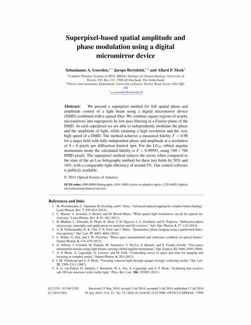
Abstract: We present a superpixel method for full spatial phase andamplitude control of a light beam using a digital micromirror device(DMD) combined with a spatial filter. We combine square regions of nearbymicromirrors into superpixels by low pass filtering in a Fourier plane of theDMD. At each superpixel we are able to independently modulate the phaseand the amplitude of light, while retaining a high resolution and the veryhigh speed of a DMD. The method achieves a measured fidelity F = 0.98for a target field with fully independent phase and amplitude at a resolutionof 8× 8 pixels per diffraction limited spot. For the LG10 orbital angularmomentum mode the calculated fidelity is F = 0.99993, using 768× 768DMD pixels. The superpixel method reduces the errors when compared tothe state of the art Lee holography method for these test fields by 50% and18%, with a comparable light efficiency of around 5%. Our control softwareis publicly available.
© 2014 Optical Society of America
OCIS codes: (090.0090) Holography; (010.1080) Active or adaptive optics; (230.4685) Opticalmicroelectromechanical devices.
References and links1. M. Woerdemann, C. Alpmann, M. Esseling, and C. Denz, “Advanced optical trapping by complex beam shaping,”
Laser Photon. Rev. 7, 839–854 (2013).2. C. Maurer, A. Jesacher, S. Bernet, and M. Ritsch-Marte, “What spatial light modulators can do for optical mi-
croscopy,” Laser Photon. Rev. 5, 81–101 (2011).3. B. Bhaduri, C. Edwards, H. Pham, R. Zhou, T. H. Nguyen, L. L. Goddard, and G. Popescu, “Diffraction phase
microscopy: principles and applications in materials and life sciences,” Adv. Opt. Photon. 6, 57–119 (2014).4. A. B. Parthasarathy, K. K. Chu, T. N. Ford, and J. Mertz, “Quantitative phase imaging using a partitioned detec-
tion aperture,” Opt. Lett. 37, 4062–4064 (2012).5. L. Waller, G. Situ, and J. W. Fleischer, “Phase-space measurement and coherence synthesis of optical beams,”
Nature Photon. 6, 474–479 (2012).6. G. Gibson, J. Courtial, M. Padgett, M. Vasnetsov, V. Pas’ko, S. Barnett, and S. Franke-Arnold, “Free-space
information transfer using light beams carrying orbital angular momentum,” Opt. Express 12, 5448–5456 (2004).7. A. P. Mosk, A. Lagendijk, G. Lerosey, and M. Fink, “Controlling waves in space and time for imaging and
focusing in complex media,” Nature Photon. 6, 283 (2012).8. I. M. Vellekoop and A. P. Mosk, “Focusing coherent light through opaque strongly scattering media,” Opt. Lett.
32, 2309–2311 (2007).9. E. G. van Putten, D. Akbulut, J. Bertolotti, W. L. Vos, A. Lagendijk, and A. P. Mosk, “Scattering lens resolves
sub-100 nm structures with visible light,” Phys. Rev. Lett. 106, 193905 (2011).
#212159 - $15.00 USD Received 15 May 2014; revised 3 Jul 2014; accepted 3 Jul 2014; published 17 Jul 2014(C) 2014 OSA 28 July 2014 | Vol. 22, No. 15 | DOI:10.1364/OE.22.017999 | OPTICS EXPRESS 17999

10. I. M. Vellekoop, E. G. van Putten, A. Lagendijk, and A. P. Mosk, “Demixing light paths inside disordered meta-materials,” Opt. Express 16, 67–80 (2008).
11. C. L. Hsieh, Y. Pu, R. Grange, and D. Psaltis, “Digital phase conjugation of second harmonic radiation emittedby nanoparticles in turbid media,” Opt. Express 18, 12283–12290 (2010).
12. X. Xu, H. Liu, and L. V. Wang, “Time-reversed ultrasonically encoded optical focusing into scattering media,”Nature Photon. 5, 154–157 (2011).
13. Y. M. Wang, B. Judkewitz, C. A. DiMarzio, and C. H. Yang, “Deep-tissue focal fluorescence imaging withdigitally time-reversed ultrasound-encoded light,” Nature Commun. 3, 928 (2012).
14. K. Si, R. Fiolka, and M. Cui, “Fluorescence imaging beyond the ballistic regime by ultrasound-pulse-guideddigital phase conjugation,” Nature Photon. 6, 657–661 (2012).
15. J. Aulbach, B. Gjonaj, P. M. Johnson, A. P. Mosk, and A. Lagendijk, “Control of light transmission throughopaque scattering media in space and time,” Phys. Rev. Lett. 106, 103901 (2011).
16. O. Katz, E. Small, Y. Bromberg, and Y. Silberberg, “Focusing and compression of ultrashort pulses throughscattering media,” Nature Photon. 5, 372–377 (2011).
17. D. J. McCabe, A. Tajalli, D. R. Austin, P. Bondareff, I. A. Walmsley, S. Gigan, and B. Chatel, “Spatio-temporalfocusing of an ultrafast pulse through a multiply scattering medium,” Nature Commun. 2, 447 (2011).
18. J. H. Park, C. Park, H. Yu, Y. H. Cho, and Y. Park, “Dynamic active wave plate using random nanoparticles,”Opt. Express 20, 17010–17016 (2012).
19. Y. F. Guan, O. Katz, E. Small, J. Y. Zhou, and Y. Silberberg, “Polarization control of multiply scattered lightthrough random media by wavefront shaping,” Opt. Lett. 37, 4663–4665 (2012).
20. J. H. Park, C. Park, H. Yu, and Y. Cho, Y. H. Park, “Active spectral filtering through turbid media,” Opt. Lett. 37,3261–3263 (2012).
21. E. Small, O. Katz, Y. F. Guan, and Y. Silberberg, “Spectral control of broadband light through random media bywavefront shaping,” Opt. Lett. 37, 3429–3431 (2012).
22. S. R. Huisman, T. J. Huisman, S. A. Goorden, A. P. Mosk, and P. W. H. Pinkse, “Programming balanced opticalbeam splitters in white paint,” Opt. Express 22, 8320–8332 (2014).
23. D. Dudley, W. Duncan, and J. Slaughter, “Emerging digital micromirror device (dmd) applications,” Proc. SPIE4985, 14–25 (2003).
24. D. Akbulut, T. J. Huisman, E. G. van Putten, W. L. Vos, and A. P. Mosk, “Focusing light through random photonicmedia by binary amplitude modulation,” Opt. Express 19, 4017–4029 (2011).
25. B. R. Brown and A. W. Lohmann, “Computer-generated binary holograms,” IBM J. Res. Develop. 13, 160–168(1969).
26. T. Kreis, P. Aswendt, and R. Hofling, “Hologram reconstruction using a digital micromirror device,” Opt. Eng.40, 926–933 (2001).
27. E. Ulusoy, L. Onural, and H. M. Ozaktas, “Synthesis of three-dimensional light fields with spatial light modula-tors,” J. Opt. Soc. Am. A 28, 1211–1223 (2011).
28. W.-H. Lee, “Computer-generated holograms: Techniques and applications,” (Elsevier, 1978), pp. 119 – 232.29. G. Tricoles, “Computer generated holograms: an historical review,” Appl. Opt. 26, 4351–4360 (1987).30. G. Nehmetallah and P. P. Banerjee, “Applications of digital and analog holography in three-dimensional imaging,”
Adv. Opt. Photon. 4, 472–553 (2012).31. W.-H. Lee, “Binary synthetic holograms,” Appl. Opt. 13, 1677–1682 (1974).32. D. B. Conkey, A. M. Caravaca-Aguirre, and R. Piestun, “High-speed scattering medium characterization with
application to focusing light through turbid media,” Opt. Express 20, 1733–1740 (2012).33. M. Mirhosseini, O. S. Magana–Loaiza, C. Chen, B. Rodenburg, M. Malik, and R. W. Boyd, “Rapid generation
of light beams carrying orbital angular momentum,” Opt. Express 21, 30196–30203 (2013).34. V. Lerner, D. Shwa, Y. Drori, and N. Katz, “Shaping Laguerre-Gaussian laser modes with binary gratings using
a digital micromirror device,” Opt. Lett. 37, 4826–4828 (2012).35. E. Ulusoy, L. Onural, and H. Ozaktas, “Full-complex amplitude modulation with binary spatial light modulators,”
J. Opt. Soc. Am. A 28, 2310–2321 (2011).36. E. G. van Putten, I. M. Vellekoop, and A. P. Mosk, “Spatial amplitude and phase modulation using commercial
twisted nematic LCDs,” Appl. Opt. 47, 2076–2081 (2008).37. S. A. Goorden, J. Bertolotti, and A. P. Mosk, Control software for superpixel-based phase and amplitude modu-
lation using a DMD, open source: https://sourceforge.net/projects/fullfieldmodulation (2014).38. A. Yao and M. Padgett, “Orbital angular momentum: origins, behavior and applications,” Adv. Opt. Photon. 3,
161–204 (2011).39. T. Puppe, I. Schuster, A. Grothe, A. Kubanek, K. Murr, P. Pinkse, and G. Rempe, “Trapping and observing single
atoms in a blue-detuned intracavity dipole trap,” Phys. Rev. Lett. 99, 013002 (2007).40. L. Allen, M. Bijersbergen, R. Spreeuw, and J. Woerdman, “Orbital angular momentum of light and the transfor-
mation of laguerre-gaussian laser modes,” Phys. Rev. A 45, 8185–8189 (1992).41. S. Hell and J. Wichmann, “Breaking the diffraction resolution limit by stimulated emission: stimulated-emission-
depletion fluorescence microscopy,” Opt. Lett. 19, 780–782 (1994).42. M. Takeda, H. Ina, and S. Kobayashi, “Fourier-transform method of fringe-pattern analysis for computer-based
#212159 - $15.00 USD Received 15 May 2014; revised 3 Jul 2014; accepted 3 Jul 2014; published 17 Jul 2014(C) 2014 OSA 28 July 2014 | Vol. 22, No. 15 | DOI:10.1364/OE.22.017999 | OPTICS EXPRESS 18000

topography and interferometry,” J. Opt. Soc. Am. 72, 156–160 (1982).
1. Introduction
Full control over light allows many exciting applications. By tailoring light fields we can nowuse optics to obtain a great level of control over particles [1]. Shaping light waves greatly im-proves our ability to see the world around us through optical microscopy [2–5] and allowsexciting technologies in the field of optical communication, crucial to support the quantityand security of the rapidly expanding amount of information that is sent around the world [6].Wavefront shaping allows compensation for and exploitation of scattering due to spatial in-homogenieties in the refractive index of a material [7]. In this way it is possible to imagethrough [8,9] and inside [10–14] opaque materials, which is of great importance in biomedicalimaging. Light propagating through an opaque material can be controlled in time by spatiallyshaping the incident wavefront [15–17] with applications such as pulse compression. Wave-front shaping also allows the use of multiple-scattering media as a tunable wave plate [18, 19],spectral filter [20,21] or tunable beamsplitter [22]. The digital micromirror device (DMD) [23]is an excellent candidate for controlling light fields, as it has a very high number of spatialdegrees of freedom, a very high framerate, it operates in a broad wavelength range and it isrelatively cheap. Each pixel of a DMD is a mirror which can be in one of two positions, cor-responding to the ‘on’ and ‘off’ states of the pixels. Wavefronts can be controlled using bi-nary amplitude modulation [24], but less efficiently than using phase modulation [8]. Shapingcomplex fields with binary masks is of continuous interest [25–27], adding to the momentumof the rapidly growing field of computer-generated holography. For reviews see [28–30]. Themost common technique to obtain phase modulation with a DMD is Lee holography [31] andhas been shown to allow for efficient and fast wavefront shaping [32]. Lee holography in itsmore general form [31] allows full field control [33]. Lee holography with pixel dithering hasbeen demonstrated and the obtained errors are at the 5% level for low resolution fields [34].A method has been proposed, but not yet demonstrated, that is based on a complex high spa-tial resolution Fourier mask and is from an information theoretic point of view optimal [35],but requires involved optics and is not robust to misalignment. We propose and demonstratea superpixel-based [36] phase and amplitude modulation method, which is highly robust andeasy to use while offering full spatial control over the phase and amplitude of a light field. Themethod is applied, through calculations as well as measurements, to two target fields of highpractical relevance: the LG10 orbital angular momentum mode and a high resolution field withfully independent amplitude and phase. The modulation accuracy of the method is quantifiedby calculating the fidelity F =
∣∣E∗targetEobtained∣∣2 and the error δ = 1−F , where Etarget is a target
field and Eobtained is the field that is obtained using the DMD. The fidelity of the superpixelmethod is found to be very high in theory as well as in experiments.
2. Setup
Our setup is designed to obtain full spatial control over the phase and amplitude of light in onespecific plane, which we call the target plane. The field behind the target plane follows fromusual beam propagation methods. Our Vialux V4100 DMD with a resolution of 1024× 768pixels and pixel pitch of 13.68µm is imaged onto the target plane using two lenses in a 4f-configuration, as illustrated in Fig. 1(a). The lenses are placed slightly off-axis with respect toeach other, resulting in an extra phase factor in the target plane. This means that the phase ofthe target plane response of a DMD pixel depends on the position of the pixel on the DMD. TheDMD is divided into superpixels: square groups of n×n micromirrors. The lenses are placed insuch a way that the phase prefactors of the micromirrors within each superpixel are distributed
#212159 - $15.00 USD Received 15 May 2014; revised 3 Jul 2014; accepted 3 Jul 2014; published 17 Jul 2014(C) 2014 OSA 28 July 2014 | Vol. 22, No. 15 | DOI:10.1364/OE.22.017999 | OPTICS EXPRESS 18001
DMDspatial filter
targetplane
EEEE
1
2
3
4
E = E + iE - E - iE1 2 3 4
4a
a0
Re(E)
Im(E) E
(b) c) (d)(
0diffraction
order
th
Aperture
(a)
r
superpixel
y
x 815
811
8
7
8
3
814
813
812
810
8
98
8
8
48
58
6
8
28
1
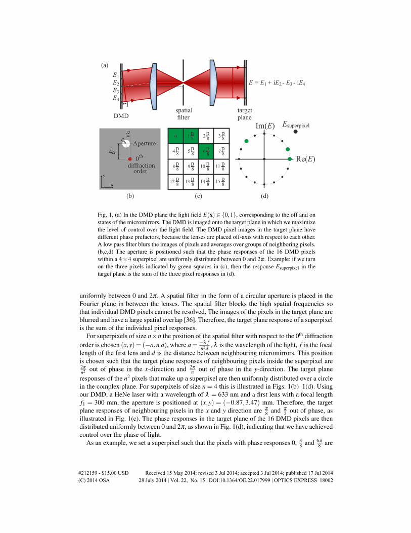
Fig. 1. (a) In the DMD plane the light field E(x) ∈ {0,1}, corresponding to the off and onstates of the micromirrors. The DMD is imaged onto the target plane in which we maximizethe level of control over the light field. The DMD pixel images in the target plane havedifferent phase prefactors, because the lenses are placed off-axis with respect to each other.A low pass filter blurs the images of pixels and averages over groups of neighboring pixels.(b,c,d) The aperture is positioned such that the phase responses of the 16 DMD pixelswithin a 4×4 superpixel are uniformly distributed between 0 and 2π . Example: if we turnon the three pixels indicated by green squares in (c), then the response Esuperpixel in thetarget plane is the sum of the three pixel responses in (d).
uniformly between 0 and 2π . A spatial filter in the form of a circular aperture is placed in theFourier plane in between the lenses. The spatial filter blocks the high spatial frequencies sothat individual DMD pixels cannot be resolved. The images of the pixels in the target plane areblurred and have a large spatial overlap [36]. Therefore, the target plane response of a superpixelis the sum of the individual pixel responses.
For superpixels of size n×n the position of the spatial filter with respect to the 0th diffractionorder is chosen (x,y) = (−a,n a), where a= −λ f
n2d , λ is the wavelength of the light, f is the focallength of the first lens and d is the distance between neighbouring micromirrors. This positionis chosen such that the target plane responses of neighbouring pixels inside the superpixel are2π
n2 out of phase in the x-direction and 2π
n out of phase in the y-direction. The target planeresponses of the n2 pixels that make up a superpixel are then uniformly distributed over a circlein the complex plane. For superpixels of size n = 4 this is illustrated in Figs. 1(b)–1(d). Usingour DMD, a HeNe laser with a wavelength of λ = 633 nm and a first lens with a focal lengthf1 = 300 mm, the aperture is positioned at (x,y) = (−0.87,3.47) mm. Therefore, the targetplane responses of neighbouring pixels in the x and y direction are π
8 and π
2 out of phase, asillustrated in Fig. 1(c). The phase responses in the target plane of the 16 DMD pixels are thendistributed uniformly between 0 and 2π , as shown in Fig. 1(d), indicating that we have achievedcontrol over the phase of light.
As an example, we set a superpixel such that the pixels with phase responses 0, π
8 and 6π
8 are
#212159 - $15.00 USD Received 15 May 2014; revised 3 Jul 2014; accepted 3 Jul 2014; published 17 Jul 2014(C) 2014 OSA 28 July 2014 | Vol. 22, No. 15 | DOI:10.1364/OE.22.017999 | OPTICS EXPRESS 18002
1/31/3
1/3
1/3Im(E)
Re(E)1/31/3
1/3
1/3Im(E)
Re(E)
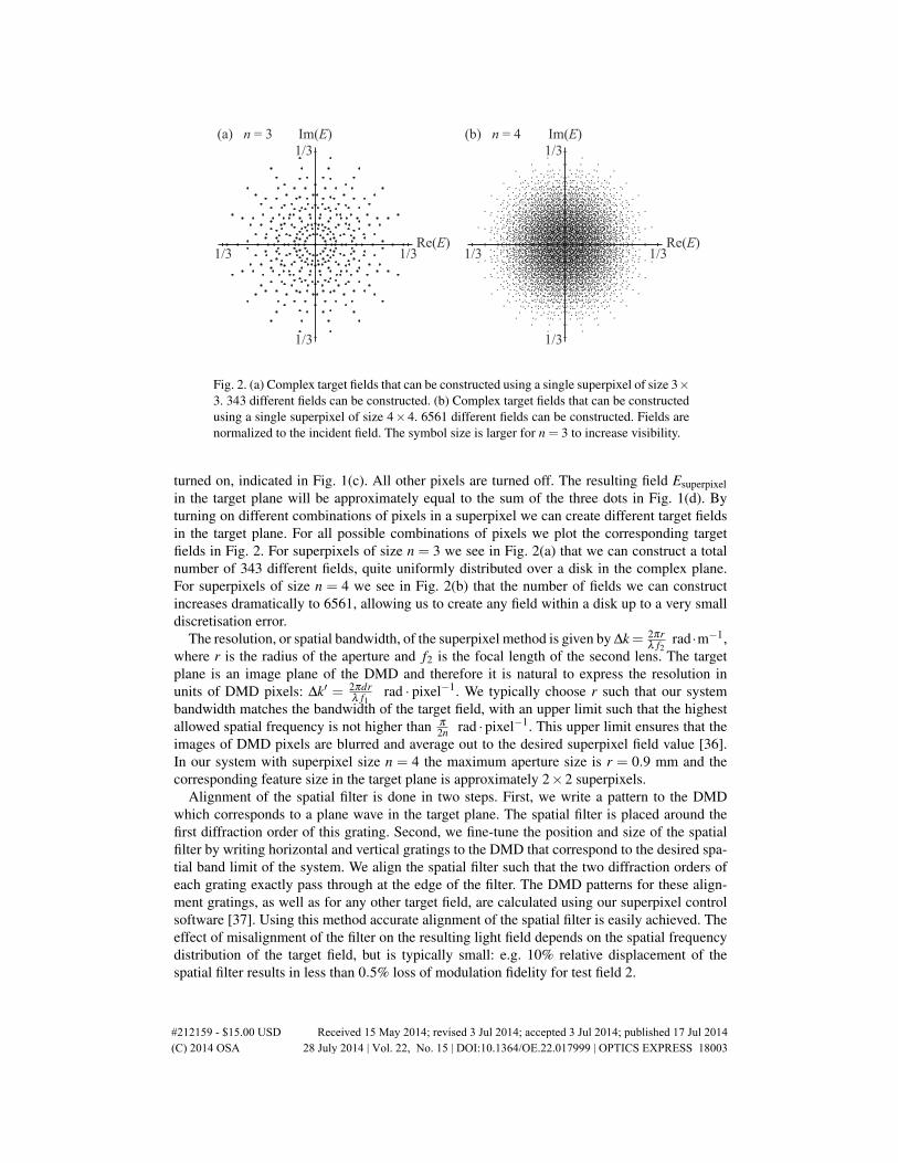
(a) n = 3 (b) n = 4
Fig. 2. (a) Complex target fields that can be constructed using a single superpixel of size 3×3. 343 different fields can be constructed. (b) Complex target fields that can be constructedusing a single superpixel of size 4×4. 6561 different fields can be constructed. Fields arenormalized to the incident field. The symbol size is larger for n = 3 to increase visibility.
turned on, indicated in Fig. 1(c). All other pixels are turned off. The resulting field Esuperpixelin the target plane will be approximately equal to the sum of the three dots in Fig. 1(d). Byturning on different combinations of pixels in a superpixel we can create different target fieldsin the target plane. For all possible combinations of pixels we plot the corresponding targetfields in Fig. 2. For superpixels of size n = 3 we see in Fig. 2(a) that we can construct a totalnumber of 343 different fields, quite uniformly distributed over a disk in the complex plane.For superpixels of size n = 4 we see in Fig. 2(b) that the number of fields we can constructincreases dramatically to 6561, allowing us to create any field within a disk up to a very smalldiscretisation error.
The resolution, or spatial bandwidth, of the superpixel method is given by ∆k= 2πrλ f2
rad ·m−1,where r is the radius of the aperture and f2 is the focal length of the second lens. The targetplane is an image plane of the DMD and therefore it is natural to express the resolution inunits of DMD pixels: ∆k′ = 2πdr
λ f1rad · pixel−1. We typically choose r such that our system
bandwidth matches the bandwidth of the target field, with an upper limit such that the highestallowed spatial frequency is not higher than π
2n rad ·pixel−1. This upper limit ensures that theimages of DMD pixels are blurred and average out to the desired superpixel field value [36].In our system with superpixel size n = 4 the maximum aperture size is r = 0.9 mm and thecorresponding feature size in the target plane is approximately 2×2 superpixels.
Alignment of the spatial filter is done in two steps. First, we write a pattern to the DMDwhich corresponds to a plane wave in the target plane. The spatial filter is placed around thefirst diffraction order of this grating. Second, we fine-tune the position and size of the spatialfilter by writing horizontal and vertical gratings to the DMD that correspond to the desired spa-tial band limit of the system. We align the spatial filter such that the two diffraction orders ofeach grating exactly pass through at the edge of the filter. The DMD patterns for these align-ment gratings, as well as for any other target field, are calculated using our superpixel controlsoftware [37]. Using this method accurate alignment of the spatial filter is easily achieved. Theeffect of misalignment of the filter on the resulting light field depends on the spatial frequencydistribution of the target field, but is typically small: e.g. 10% relative displacement of thespatial filter results in less than 0.5% loss of modulation fidelity for test field 2.
#212159 - $15.00 USD Received 15 May 2014; revised 3 Jul 2014; accepted 3 Jul 2014; published 17 Jul 2014(C) 2014 OSA 28 July 2014 | Vol. 22, No. 15 | DOI:10.1364/OE.22.017999 | OPTICS EXPRESS 18003

3. Efficiency, bandwidth and implementation
The efficiency of the superpixel method is equal to the maximum intensity a superpixel can cre-ate. The maximum intensity is obtained by turning on exactly half of the pixels in a superpixel,e.g. the upper 8 pixels in Fig. 1(c). This coincides with the maximum amplitude in Fig. 2(b).The calculated efficiency of the modulation method is then 10.3% of the incident intensity.The measured 0 order diffraction efficiency of the DMD itself is 60% for our DMD and ourmeasured modulation efficiency is 7%. The total measured efficiency of our implementationof the superpixel method is 4%. This is similar to the efficiency of Lee holography, since bothmethods are based on filtering out the first order of an intensity diffraction grating.
Wavelength dispersion of the amplitude mask formed by the DMD limits the frequency band-width in which the superpixel method works. The superpixel-based phase and amplitude mod-ulation method can be set up for any wavelength λ at which the DMD functions. The positionand size of the spatial filter depend on λ . Illuminating the DMD with light of a different wave-length, e.g. λ +∆λ , decreases the modulation fidelity. The error induced in the target plane is,to first order, a phase gradient added to the target field. The period of the phase gradient is equalto |nλ/∆λ | DMD pixels. For DMD chips of approximately 1000 pixels this phase gradient issignificant for |∆λ/λ | > 0.1%. However, apart from this phase gradient the obtained field hasa high fidelity until |∆λ/λ | ≈ 10%, at which point the field in the Fourier plane is so muchdisplaced that the light starts to miss the spatial filter.
A lookup table is used to make the connection between the desired target field at a superpixeland the combination of pixels within the superpixel that should be turned on in order to createthat field. By using a lookup table the calculations needed to determine which DMD pixelsto turn on are minimized and therefore the performance is optimized. We define a sufficientlyfine square grid of possible target fields in the complex plane. We create a lookup table whichcontains for every point on this grid the nearest field the superpixel method can create as wellas the combination of pixels that should be turned on in order to create this field. The size ofthe lookup table is chosen to be 855× 855 points, about 100 times more dense than the set ofpossible target fields at superpixel size n = 4. In our implementation it takes under 4 MB ofmemory to store the table. Loading the table and using it to look up a DMD pattern is donewithin a fraction of a second.
4. Test field 1: LG10 mode
In order to test our method two test fields are constructed using superpixels of size n = 4. Thefirst test field is a LG10 ‘donut’ mode with an orbital angular momentum of l = 1, where l is theazimuthal mode number. These modes have many applications [38], including micromanipula-tion [39, 40], imaging [41] and communication [6]. The intensity and phase profiles of such amode are shown in Figs. 3(a) and 3(b). In order to apply our superpixel method, we normalizethe amplitude of the LG10 mode to the maximum amplitude our method can create. For eachsuperpixel we determine the pixel values using the lookup table. The resulting pattern on theDMD is shown in Fig. 3(c). For this low-resolution target field we tune the size r of the spatialfilter such that ∆k′ = π
100 rad · pixel−1. This corresponds to a feature size of approximately100× 100 DMD pixels and for our system this means r = 0.07 mm. From the DMD patternwe calculate the resulting target field by first applying a fast Fourier transform for the first lens,then a multiplication with a circular mask for the spatial filter and finally a second fast Fouriertransform for the second lens. The intensity and phase profiles of the obtained field are shownin Figs. 3(d) and 3(e). We observe an excellent match, apart from the phase in the corners whichis not well defined as the intensity of the ideal LG10 mode is negligible there. The fidelity of thesuperpixel method for this target field is calculated to be Fsuperpixel = 0.99993. In other words,a fraction of only δsuperpixel = 7 ·10−5 of the light goes to other modes.
#212159 - $15.00 USD Received 15 May 2014; revised 3 Jul 2014; accepted 3 Jul 2014; published 17 Jul 2014(C) 2014 OSA 28 July 2014 | Vol. 22, No. 15 | DOI:10.1364/OE.22.017999 | OPTICS EXPRESS 18004

-3 -2 -1 0 1 2 3
h
e
b
0 2 4 6 x10⁻⁶
g
d
a
0 768
768 c
0 768
768
off on
f
n/aLG
Superpixel
Lee
DMD pattern Intensity Phase
10
Fig. 3. (a,b) Intensity and phase of the target LG10 mode. (c) DMD pattern for the LG10mode when using the superpixel method. Inset: zoom-in on 20× 20 DMD pixels. (d,e)Calculated intensity and phase using the superpixel method; δsuperpixel = 7 ·10−5. (f) DMDpattern for the LG10 mode when using Lee holography with kx = ky =
2π
30 pixel−1. Inset:zoom-in on 20×20 DMD pixels. (g,h) Calculated intensity and phase using Lee hologra-phy; δLee = 9 ·10−5. Intensities are normalized to total intensity.
The present reference method is Lee holography [31]. Lee holography has two parameters:the size of the spatial filter and the spatial carrier frequency k. The size of the spatial filterand therefore the system resolution are kept the same as when using the superpixel method. kis optimized to obtain maximum fidelity. The best result, which is obtained using kx = ky =2π
30 pixel−1, is shown in Figs. 3(f)–3(h). Using this method the error δLee = 9 · 10−5. Bothmethods allow generation of a LG10 mode with very high fidelity using a DMD of standardsize. The superpixel method is most accurate, offering a 18% reduction of error compared toLee holography.
5. Test field 2: Image quality
Next, we consider a high resolution target field with uncorrelated intensity and phase. Wechoose a field which contains the picture of a dog in the intensity and a picture of a cat inthe phase of the field, as shown in Figs. 4(a) and 4(b). Holographic methods are often used toproject images and fully independent control over phase and amplitude of light is desired inmany applications such as phase contrast microscopy [4]. Moreover, using this test field we
#212159 - $15.00 USD Received 15 May 2014; revised 3 Jul 2014; accepted 3 Jul 2014; published 17 Jul 2014(C) 2014 OSA 28 July 2014 | Vol. 22, No. 15 | DOI:10.1364/OE.22.017999 | OPTICS EXPRESS 18005

Target
Superpixel
Lee
DMD pattern Intensity Phase
n/a
-3 -2 -1 0 1 2 30 x10-61 2 3
768
10240
off on
0 1024
768
h
e
b
g
d
a
f
c
Fig. 4. (a,b) Intensity and phase of a high resolution target field. (c) DMD pattern accordingto the superpixel method. Inset: zoom-in on 20× 20 DMD pixels. (d,e) Calculated inten-sity and phase using the superpixel method; δ ∆k
superpixel = 0.8%. (f) DMD pattern according
to the Lee method using kx = ky =2π
12 pixel−1. Inset: zoom-in on 20× 20 DMD pixels.(g,h) Calculated intensity and phase using the Lee method; δ ∆k
Lee = 1.6%. Intensities arenormalized to total intensity.
show that the superpixel method can obtain a high resolution. We use superpixels of size n = 4and in order to allow for a high resolution we use an aperture size r = 0.9 mm, which meansthe minimum feature size is 2× 2 superpixels. Any imaging system, and therefore any modu-lation method, has a finite resolution due to apertures in the system and the finite extent of theoptics. This finite resolution leads to inevitable correlations between amplitude and phase oflight fields. In particular, it is impossible to make very large phase gradients without the ampli-tude becoming zero. For the current test field and resolution, the theoretical maximum fidelitythat can be achieved is given by F∆k
theoretical =∣∣E∗targetE
∆ktarget
∣∣2 = 0.955, where E∆ktarget is the spatial
bandwidth limited target field.The DMD pattern and corresponding intensity and phase profiles that are obtained when
using the superpixel method are shown in Figs. 4(c)–4(e). We optimize Lee holography and findthe optimum for kx = ky =
2π
12 pixel−1. The resulting DMD pattern and obtained intensity andphase patterns are shown in Figs. 4(f)–4(h). In both cases we observe some undesired ripplesin the obtained intensity profile, because the steepest phase gradients in the target field cannotbe resolved by the 8 DMD pixel resolution of the superpixel and Lee methods. We observethat the reconstructed intensity is more accurate when using the superpixel method. For thesuperpixel method we find a fidelity of Fsuperpixel = 0.947 = 0.992F∆k
theoretical, showing that thefidelity is almost the theoretical maximum for the 8 pixel resolution. The error with respect tothe bandwidth limited target is δ ∆k
superpixel = 0.8%. For Lee holography we find δ ∆kLee = 1.6%.
The superpixel method offers a large improvement, reducing the error by 50% compared to Lee
#212159 - $15.00 USD Received 15 May 2014; revised 3 Jul 2014; accepted 3 Jul 2014; published 17 Jul 2014(C) 2014 OSA 28 July 2014 | Vol. 22, No. 15 | DOI:10.1364/OE.22.017999 | OPTICS EXPRESS 18006
HeNe 633 nm
ND1
ND1
BE 20x
50:50 BS
50:50 BS300 mm 150 mm CCDDMD
Reference beam
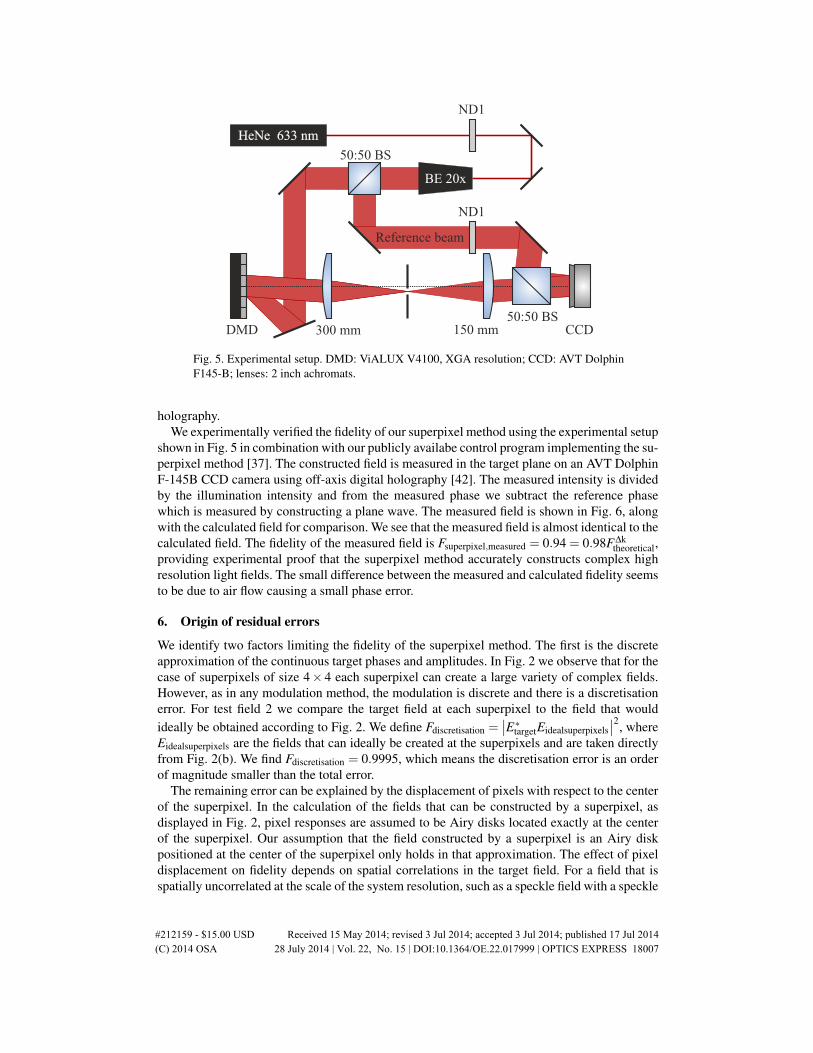
Fig. 5. Experimental setup. DMD: ViALUX V4100, XGA resolution; CCD: AVT DolphinF145-B; lenses: 2 inch achromats.
holography.We experimentally verified the fidelity of our superpixel method using the experimental setup
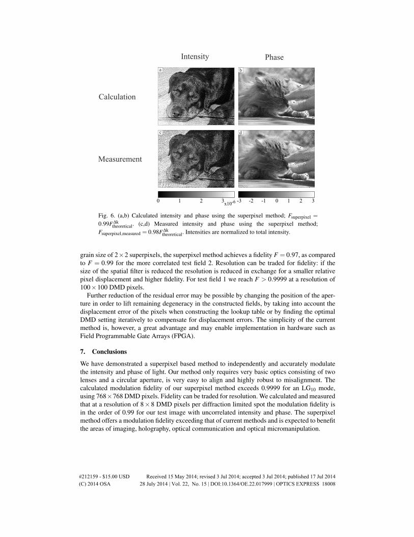
shown in Fig. 5 in combination with our publicly availabe control program implementing the su-perpixel method [37]. The constructed field is measured in the target plane on an AVT DolphinF-145B CCD camera using off-axis digital holography [42]. The measured intensity is dividedby the illumination intensity and from the measured phase we subtract the reference phasewhich is measured by constructing a plane wave. The measured field is shown in Fig. 6, alongwith the calculated field for comparison. We see that the measured field is almost identical to thecalculated field. The fidelity of the measured field is Fsuperpixel,measured = 0.94 = 0.98F∆k
theoretical,providing experimental proof that the superpixel method accurately constructs complex highresolution light fields. The small difference between the measured and calculated fidelity seemsto be due to air flow causing a small phase error.
6. Origin of residual errors
We identify two factors limiting the fidelity of the superpixel method. The first is the discreteapproximation of the continuous target phases and amplitudes. In Fig. 2 we observe that for thecase of superpixels of size 4× 4 each superpixel can create a large variety of complex fields.However, as in any modulation method, the modulation is discrete and there is a discretisationerror. For test field 2 we compare the target field at each superpixel to the field that wouldideally be obtained according to Fig. 2. We define Fdiscretisation =
∣∣E∗targetEidealsuperpixels∣∣2, where
Eidealsuperpixels are the fields that can ideally be created at the superpixels and are taken directlyfrom Fig. 2(b). We find Fdiscretisation = 0.9995, which means the discretisation error is an orderof magnitude smaller than the total error.
The remaining error can be explained by the displacement of pixels with respect to the centerof the superpixel. In the calculation of the fields that can be constructed by a superpixel, asdisplayed in Fig. 2, pixel responses are assumed to be Airy disks located exactly at the centerof the superpixel. Our assumption that the field constructed by a superpixel is an Airy diskpositioned at the center of the superpixel only holds in that approximation. The effect of pixeldisplacement on fidelity depends on spatial correlations in the target field. For a field that isspatially uncorrelated at the scale of the system resolution, such as a speckle field with a speckle
#212159 - $15.00 USD Received 15 May 2014; revised 3 Jul 2014; accepted 3 Jul 2014; published 17 Jul 2014(C) 2014 OSA 28 July 2014 | Vol. 22, No. 15 | DOI:10.1364/OE.22.017999 | OPTICS EXPRESS 18007
Calculation
Measurement
Intensity Phase
-3 -2 -1 0 1 2 30x10-6
1 2 3
d
b
c
a
Fig. 6. (a,b) Calculated intensity and phase using the superpixel method; Fsuperpixel =
0.99F∆ktheoretical. (c,d) Measured intensity and phase using the superpixel method;
Fsuperpixel,measured = 0.98F∆ktheoretical. Intensities are normalized to total intensity.
grain size of 2×2 superpixels, the superpixel method achieves a fidelity F = 0.97, as comparedto F = 0.99 for the more correlated test field 2. Resolution can be traded for fidelity: if thesize of the spatial filter is reduced the resolution is reduced in exchange for a smaller relativepixel displacement and higher fidelity. For test field 1 we reach F > 0.9999 at a resolution of100×100 DMD pixels.
Further reduction of the residual error may be possible by changing the position of the aper-ture in order to lift remaining degeneracy in the constructed fields, by taking into account thedisplacement error of the pixels when constructing the lookup table or by finding the optimalDMD setting iteratively to compensate for displacement errors. The simplicity of the currentmethod is, however, a great advantage and may enable implementation in hardware such asField Programmable Gate Arrays (FPGA).
7. Conclusions
We have demonstrated a superpixel based method to independently and accurately modulatethe intensity and phase of light. Our method only requires very basic optics consisting of twolenses and a circular aperture, is very easy to align and highly robust to misalignment. Thecalculated modulation fidelity of our superpixel method exceeds 0.9999 for an LG10 mode,using 768×768 DMD pixels. Fidelity can be traded for resolution. We calculated and measuredthat at a resolution of 8× 8 DMD pixels per diffraction limited spot the modulation fidelity isin the order of 0.99 for our test image with uncorrelated intensity and phase. The superpixelmethod offers a modulation fidelity exceeding that of current methods and is expected to benefitthe areas of imaging, holography, optical communication and optical micromanipulation.
#212159 - $15.00 USD Received 15 May 2014; revised 3 Jul 2014; accepted 3 Jul 2014; published 17 Jul 2014(C) 2014 OSA 28 July 2014 | Vol. 22, No. 15 | DOI:10.1364/OE.22.017999 | OPTICS EXPRESS 18008

Acknowledgments
We thank Duygu Akbulut, Hasan Yılmaz, Henri Thyrrestrup, Michael J. Van De Graaff, PepijnW.H. Pinkse, Ad Lagendijk and Willem L. Vos for discussions. This work is part of the re-search program of the Stichting voor Fundamenteel Onderzoek der Materie (FOM). A.P.M.acknowledges European Research Council grant no. 279248.
#212159 - $15.00 USD Received 15 May 2014; revised 3 Jul 2014; accepted 3 Jul 2014; published 17 Jul 2014(C) 2014 OSA 28 July 2014 | Vol. 22, No. 15 | DOI:10.1364/OE.22.017999 | OPTICS EXPRESS 18009