Embed Size (px)
Citation preview
Optical Investigations of Spray Processes in Diesel
Engines
Clément Chartier
Thesis for the Degree of Licentiate in Engineering
Division of Combustion EnginesDepartment of Energy SciencesFaculty of EngineeringLund University
LUND UNIVERSITY

ISRN LUTMDN/TMHP--10/7071--SEISSN 0282-1990
Division of Combustion EnginesDepartment Energy SciencesFaculty of EngineeringLund UniversityP.O. Box 118SE-22100 LundSweden
©Clément Chartier, All rights reservedPrinted in Sweden by Media-Tryck, Lund November 2010
List of publications
Paper I
Analysis of Smokeless Spray Combustion in a Heavy-Duty Diesel Engine by Combined Simultaneous Optical Diagnostics
Clément Chartier, Ulf Aronsson, Öivind Andersson, Rolf EgnellDivision of Combustion Engines, Lund University, Sweden
Robert Collin, Hans Seyfried, Mattias Richter, Marcus AldènDivision of Combustion Physics, Lund University, Sweden
SAE Technical paper 2009-01-1353
Paper II
Effect of Injection Strategy on Cold Start Performance in an Optical Light-Duty DI Diesel Engine
Clément Chartier, Ulf Aronsson, Öivind Andersson, Rolf EgnellDivision of Combustion Engines, Lund University, Sweden
SAE International Journal of Engines, March 2010 2:431-442
Paper III
Effects of Post-Injection Strategies on Near-Injector Over-Lean Mixtures and Unburned Hydrocarbon Emission in a Heavy-Duty Optical Diesel Engine
Clément Chartier, Öivind Andersson, Bengt JohanssonDivision of Combustion Engines, Lund University, Sweden
Mohan K. Bobba, Mark P. MusculusSandia National Laboratories Livermore, CA, United States
Submitted to SAE World Congress 2011
Other related work
Heat Release Comparison Between Optical and All-Metal HSDI Diesel Engines
Ulf Aronsson, Clément Chartier, Uwe Horn, Öivind Andersson, Bengt Johansson, Rolf Egnell
Division of Combustion Engines, Lund University, SwedenSAE Technical paper 2008-01-1062
I
Analysis of the Correlation Between Engine-Out Particulates and Local Φ in the Lift-Off Region of a Heavy Duty Diesel Engine Using Raman Spectroscopy
Ulf Aronsson, Clément Chartier, Öivind Andersson, Rolf EgnellDivision of Combustion Engines, Lund University, Sweden
Johan Sjöholm, Mattias Richter, Marcus AldénDivision of Combustion Physics, Lund University, Sweden
SAE International Journal of Fuels and Lubricants October 2009 vol. 2 no. 1 645-660
Planar Laser-Diagnostics of Soot and OH with Post-Injections in a Heavy-Duty LTC Diesel Engine
Mohan K. Bobba and Mark P. MusculusSandia National Laboratories Livermore, CA, United States
Clément Chartier, Öivind Andersson, Bengt JohanssonDivision of Combustion Engines, Lund University, Sweden
Presented at Thiesel 2010, Valencia, Spain
Analysis of EGR Effects on the Soot Distribution in a Heavy Duty Diesel Engine using Time-Resolved Laser Induced Incandescence
Ulf Aronsson, Clément Chartier, Öivind AnderssonDivision of Combustion Engines, Lund University, Sweden
Johan Sjöholm, Rikard Wellander, Mattias Richter, Marcus AldénDivision of Combustion Physics, Lund University, Sweden
Paul C. MilesSandia National Laboratories Livermore, CA, United States
SAE Technical paper 2010-01-2104
Impact of Mechanical Deformation due to Pressure, Mass, and Thermal Forces on the In-Cylinder Volume Trace In Optical Engines of Bowditch Design
Ulf Aronsson, Hadeel Solaka, Clément Chartier, Öivind Andersson, Bengt JohanssonDivision of Combustion Engines, Lund University, Sweden
Submitted to SIAT2011, paper number 119
II

Challenges for In-cylinder High-Speed Two-Dimensional Laser-Induced Incandescence Measurements of Soot
Johan Sjöholm, Rikard Wellander, Mattias Richter, Marcus Aldén, Division of Combustion Physics, Lund University, Sweden
Ulf Aronsson, Clément Chartier, Öivind Andersson, Bengt Johansson, Division of Combustion Engines, Lund University, Sweden
Submitted to SAE World Congress 2011 paper no.11PFL-0985
III

Acknowledgements
There are many persons that I would like to thank for their contributions to this work. First of all, my supervisor, Öivind Andersson, who has been a great support in all aspects involved in Ph.D. studies. His intersest in french biofuels and cuisine have brought many interesting conversations along the years.
Rolf Egnell who was my supervisor at the beginning of this thesis has brought many ideas and has been a great source of inspiration. Some say he owns every single model Citroën has made!
I would also like to thank my co-supervisor Professor Bengt Johansson who always has ideas and answers about combustion engines, or anything that has electronic in it.
I am also grateful to my colleagues from the combustion physics department for their expertise on laser diagnostics and collaboration in our measurement campaigns. It is always a special moment when engines and lasers happen to work at the same time. I also want to acknowledge our meticulous technician Jan-Erik Nilsson, who retired this year, for having kept the lab in perfect condition. People usually don’t believe that we have actually worked in this lab. Kjell Jonholm is now technician in the lab and I am sure that it is in good hands.
A great thanks to the industrial members of the GenDies group for a very fruitful collaboration. Their guidance on future research subjects and open-mindedness to suggestions contribute largely to making this project very pleasant and motivating.
Earlier this year I have had the opportunity to stay for three months as a guest researcher at Sandia national labs in Livermore. I am very thankful to all the persons who made this visit possible both in Lund and at Sandia. It was a very enriching period where I have had the chance to meet accessible and inspiring persons. A special thanks to Mark Musculus and Mohan Bobba for their hospitality, support and ideas. They made everything possible in order to help me finish the experiments in time before the end of my stay, and it worked out.
Finally, I would like to thank all my colleagues and friends at the division of combustion engines for making the daily life at work more enjoyable. I sincerly appreciate the good discussions and laughs every day, thank you for all that! A special thanks to Ulf Aronsson for getting me into this in the first place and especially for his help and friendship.
IV
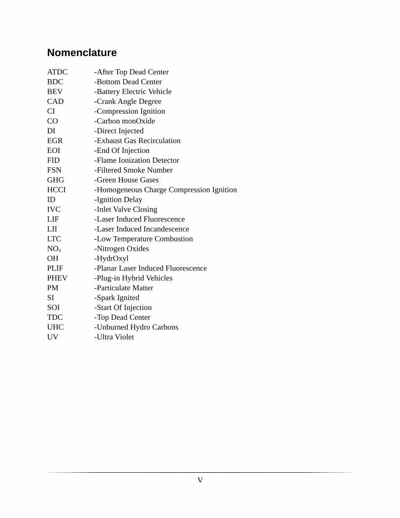
Nomenclature
ATDC -After Top Dead CenterBDC -Bottom Dead CenterBEV -Battery Electric VehicleCAD -Crank Angle DegreeCI -Compression IgnitionCO -Carbon monOxideDI -Direct InjectedEGR -Exhaust Gas RecirculationEOI -End Of InjectionFID -Flame Ionization DetectorFSN -Filtered Smoke NumberGHG -Green House GasesHCCI -Homogeneous Charge Compression IgnitionID -Ignition DelayIVC -Inlet Valve ClosingLIF -Laser Induced FluorescenceLII -Laser Induced IncandescenceLTC -Low Temperature CombustionNOx -Nitrogen OxidesOH -HydrOxylPLIF -Planar Laser Induced FluorescencePHEV -Plug-in Hybrid VehiclesPM -Particulate MatterSI -Spark IgnitedSOI -Start Of InjectionTDC -Top Dead CenterUHC -Unburned Hydro CarbonsUV -Ultra Violet
V
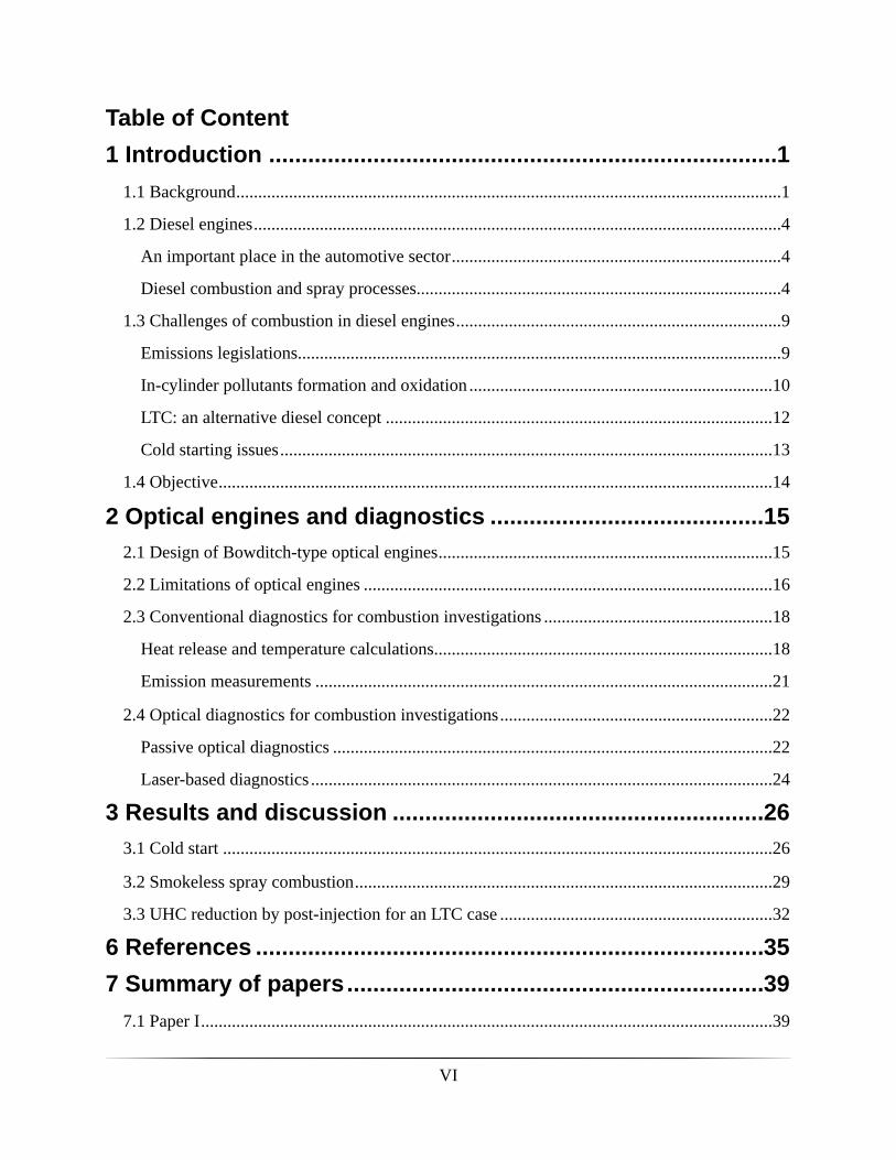
Table of Content..............................................................................1 Introduction 1
............................................................................................................................1.1 Background 1
........................................................................................................................1.2 Diesel engines 4
...........................................................................An important place in the automotive sector 4
...................................................................................Diesel combustion and spray processes 4
..........................................................................1.3 Challenges of combustion in diesel engines 9
..............................................................................................................Emissions legislations 9
.....................................................................In-cylinder pollutants formation and oxidation 10
........................................................................................LTC: an alternative diesel concept 12
................................................................................................................Cold starting issues 13
..............................................................................................................................1.4 Objective 14
..........................................2 Optical engines and diagnostics 15............................................................................2.1 Design of Bowditch-type optical engines 15
.............................................................................................2.2 Limitations of optical engines 16
....................................................2.3 Conventional diagnostics for combustion investigations 18
.............................................................................Heat release and temperature calculations 18
........................................................................................................Emission measurements 21
..............................................................2.4 Optical diagnostics for combustion investigations 22
....................................................................................................Passive optical diagnostics 22
.........................................................................................................Laser-based diagnostics 24
.........................................................3 Results and discussion 26.............................................................................................................................3.1 Cold start 26
...............................................................................................3.2 Smokeless spray combustion 29
..............................................................3.3 UHC reduction by post-injection for an LTC case 32
..............................................................................6 References 35................................................................7 Summary of papers 39
..................................................................................................................................7.1 Paper I 39
VI

.................................................................................................................................7.2 Paper II 39
...............................................................................................................................7.3 Paper III 40
VII

VIII
1 Introduction
1.1 Background
Internal combustion engines have been an important technological field for more than a century. This has had an important impact on society through improved transportation and industrial applications. Although the basic principle of the four-stroke engine has not changed since Beau de Rochas’ patent in 1862, four-stroke engines have continuously been under development and still are. Reliability and output performance were the main domains of improvement until the second half of the twentieth century ,whereafter the focus has shifted to exhaust gas emissions and fuel consumption.
Concerns about the effects of green house gases (GHG) on climate changes has brought carbon dioxide, a major GHG, to the front scene of emissions discussions. A recent analysis showed that 23% of the UK’s carbon dioxide emissions originate from internal combustion engines used in transportation, compared to 14% in 1980 [1]. These figures are representative of most western countries and show the need for research towards more fuel efficient solutions leading to lowered carbon dioxide emissions.
Due to its higher fuel efficiency, the diesel engine is interesting in the search for more energy efficient transports. However, as will be discussed later, stringent emissions legislations are challenging for diesel engine and highlight the need for cleaner combustion and advanced after-treatment systems.
Alternative solutions to conventional powertrains, based on internal combustion engines, have emerged and been developed in the past few years. Examples are fuel cell vehicles, battery electric vehicles (BEV), and plug-in hybrid vehicles (PHEV), especially for light duty applications. These solutions offer an obvious tank-to-wheel carbon dioxide emission improvement, and even elimination in the case of the fuel cell or BEV.
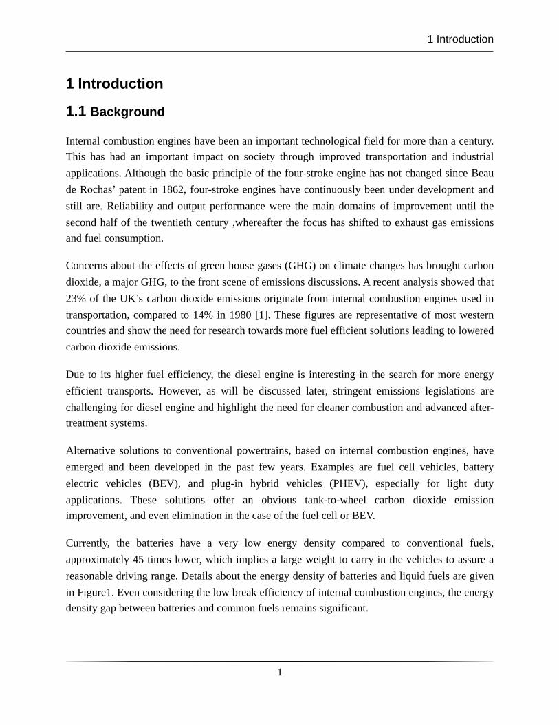
Currently, the batteries have a very low energy density compared to conventional fuels, approximately 45 times lower, which implies a large weight to carry in the vehicles to assure a reasonable driving range. Details about the energy density of batteries and liquid fuels are given in Figure1. Even considering the low break efficiency of internal combustion engines, the energy density gap between batteries and common fuels remains significant.
1 Introduction
1
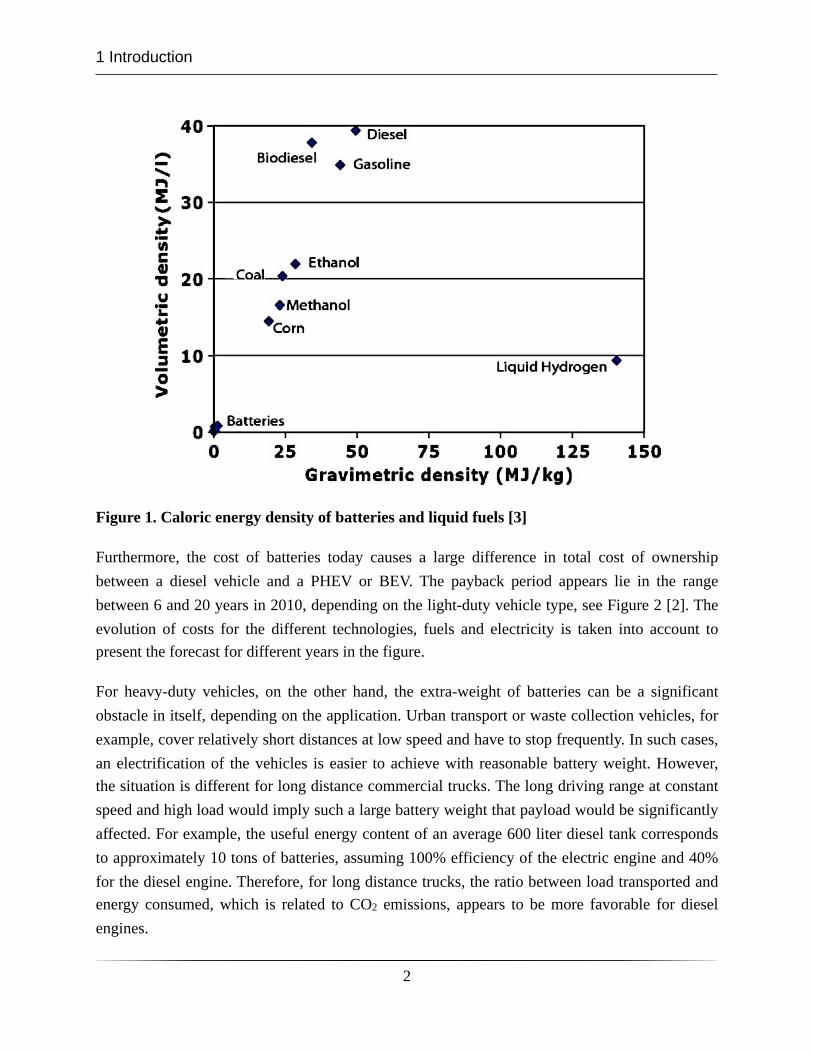
Figure 1. Caloric energy density of batteries and liquid fuels [3]
Furthermore, the cost of batteries today causes a large difference in total cost of ownership between a diesel vehicle and a PHEV or BEV. The payback period appears lie in the range between 6 and 20 years in 2010, depending on the light-duty vehicle type, see Figure 2 [2]. The evolution of costs for the different technologies, fuels and electricity is taken into account to present the forecast for different years in the figure.
For heavy-duty vehicles, on the other hand, the extra-weight of batteries can be a significant obstacle in itself, depending on the application. Urban transport or waste collection vehicles, for example, cover relatively short distances at low speed and have to stop frequently. In such cases, an electrification of the vehicles is easier to achieve with reasonable battery weight. However, the situation is different for long distance commercial trucks. The long driving range at constant speed and high load would imply such a large battery weight that payload would be significantly affected. For example, the useful energy content of an average 600 liter diesel tank corresponds to approximately 10 tons of batteries, assuming 100% efficiency of the electric engine and 40% for the diesel engine. Therefore, for long distance trucks, the ratio between load transported and energy consumed, which is related to CO2 emissions, appears to be more favorable for diesel engines.
1 Introduction
2
Figure 2. Payback period for off-setting the initial investment compared to an advanced gasoline vehicle. The annual mileage was approximated to 15 000 km. [2]
Another important factor is carbon dioxide emitted during electricity generation. The well-to-wheel analysis gives a more global view of the problem than solely tank-to-wheel. Within European countries, for example, the CO2 emissions per unit of electricity generated varies largely. In the lowest case, a theoretical mid-size BEV would emit 8g CO2 emissions per km from well-to-wheel and 203g in the highest case, when a diesel version of this vehicle would emit 118g CO2 emissions per km. [2]. When it comes to fuel cells, the production and transport of hydrogen causes a poor overall efficiency and significant CO2 emissions [4,5,6]. For this reason, fuel cells have become less attractive powertrain solutions for mobile applications.
To summarize, considering global costs, battery weight, and well-to-wheel emissions, the different solutions have both advantages and challenges to consider. The situation in 2010 reveals significantly higher costs for electrified vehicles compared to diesel and the CO2 emissions are not necessarily lower depending on the method of electricity generation. Developments in battery technology, internal combustion engines, electricity generation, and fuel costs will make the situation evolve over the coming decades. However, the diesel engine plays a major role in the transport sector and the potential for improvements makes it a viable solution.
1 Introduction
3
1.2 Diesel engines
An important place in the automotive sector
Diesel engines are dominant in the heavy-duty sector due to their lower specific fuel consumption and higher torque performance compared to gasoline engines. For light-duty applications, the share of diesels varies largely in time and location but a significant increasing trend is observed. In the european union (UE15), 51.9% of of passenger car registrations were diesels in January 2009 whereas they represented a share of only 29% in 1999 [7]. The geographical disparities are large. In Sweden, for example, this share evolved from 7.2 to 40% during the same period and 54.3 to 70.3% in Belgium [7]. However, despite differences in absolute market share levels and increase rates, all countries within the UE15 show a growing interest in light-duty diesel vehicles.
Diesel engines have seen significant improvements in terms of driving comfort and performance in the last decade, contributing to this trend. However, the higher fuel efficiency of the diesel engine compared to spark-ignited (SI) engines is a major factor behind this trend in the context of CO2 emissions reductions and unstable fuel prices.
The low fuel consumption of the diesel engine compared to its competitors was one major goal of Rudolf Diesel when developing his compression ignition concept in the 1890’s [8]. The part load pumping losses of the diesel engine are significantly lower compared to SI since the intake air is not throttled. This is because the diesel engine works with excess air. Furthermore, as fuel is injected during the compression stroke and relies on auto-ignition to start the combustion, the compression ratio of diesel engine is higher compared to SI engines since knocking is not an issue. A higher compression ratio increases the thermodynamic efficiency and contributes to the higher brake efficiency of the diesel engine.
Diesel combustion and spray processes
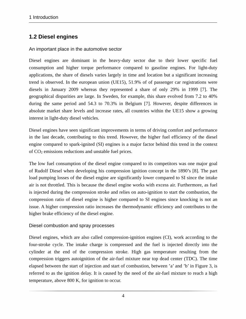
Diesel engines, which are also called compression-ignition engines (CI), work according to the four-stroke cycle. The intake charge is compressed and the fuel is injected directly into the cylinder at the end of the compression stroke. High gas temperature resulting from the compression triggers autoignition of the air-fuel mixture near top dead center (TDC). The time elapsed between the start of injection and start of combustion, between ’a’ and ’b’ in Figure 3, is referred to as the ignition delay. It is caused by the need of the air-fuel mixture to reach a high temperature, above 800 K, for ignition to occur.
1 Introduction
4
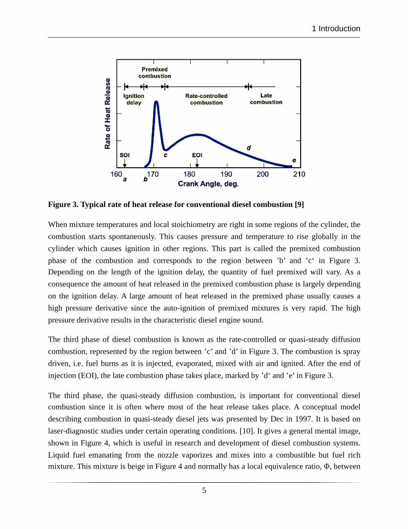
Figure 3. Typical rate of heat release for conventional diesel combustion [9]
When mixture temperatures and local stoichiometry are right in some regions of the cylinder, the combustion starts spontaneously. This causes pressure and temperature to rise globally in the cylinder which causes ignition in other regions. This part is called the premixed combustion phase of the combustion and corresponds to the region between ’b’ and ’c‘ in Figure 3. Depending on the length of the ignition delay, the quantity of fuel premixed will vary. As a consequence the amount of heat released in the premixed combustion phase is largely depending on the ignition delay. A large amount of heat released in the premixed phase usually causes a high pressure derivative since the auto-ignition of premixed mixtures is very rapid. The high pressure derivative results in the characteristic diesel engine sound.
The third phase of diesel combustion is known as the rate-controlled or quasi-steady diffusion combustion, represented by the region between ’c’ and ’d’ in Figure 3. The combustion is spray driven, i.e. fuel burns as it is injected, evaporated, mixed with air and ignited. After the end of injection (EOI), the late combustion phase takes place, marked by ’d‘ and ’e’ in Figure 3.
The third phase, the quasi-steady diffusion combustion, is important for conventional diesel combustion since it is often where most of the heat release takes place. A conceptual model describing combustion in quasi-steady diesel jets was presented by Dec in 1997. It is based on laser-diagnostic studies under certain operating conditions. [10]. It gives a general mental image, shown in Figure 4, which is useful in research and development of diesel combustion systems. Liquid fuel emanating from the nozzle vaporizes and mixes into a combustible but fuel rich mixture. This mixture is beige in Figure 4 and normally has a local equivalence ratio, Φ, between
1 Introduction
5
2 and 4. A narrow, light-blue zone of fuel-rich premixed combustion surrounds this mixture. Soot formation starts from this region if the local equivalence ratio is above a sooting threshold value of about two [11]. The soot formation process continues in the downstream regions (dark blue and red-yellow in the figure) and soot particles increase in size until they reach the head of the jet.
A hot diffusion flame is located at the periphery of the jet where OH is observed and it is hypothesized that most of the thermal NO is formed in this region. This high temperature envelope around the jet is also where soot is oxidized by OH radicals. The distance between the nozzle orifice and the most upstream part of the OH envelope, referred to as the lift-off length, is an important parameter of diesel jets. The air entrainment rate into the central parts of the jet is the largest along this portion and, as mentioned previously, the equivalence ratio reached in the lift-off region influences the soot production processes [12,13,14].
Air entrainment into the jet still occurs downstream of the lift-off region but, as the diffusion flame consumes a significant amount of oxygen, it does not tend to affect the equivalence ratio in the inner region of the jet.
It should be noted that the conceptual model was based on measurements at given operating conditions. Use of exhaust gas recirculation (EGR), change in nozzle dimensions, injection pressure, fuel properties or in-cylinder conditions will affect this picture in terms of the sizes or precise locations of certain zones.
Figure 4. Conceptual model of a quasi-steady diesel jet by Dec. Reproduced from [10]
1 Introduction
6
Modern diesel engines are equipped with high pressure fuel pumps capable of pressures in the range of 2000 bar or 2500 bar, for light- and heavy-duty applications, respectively. It makes it possible to inject the fuel mass required for full load operation with relatively small nozzle orifices in the range of 0.1 to 0.2 mm. Small orifices and high injection pressures enhance atomization, i.e. break-up of liquid fuel into droplets. This results in a large total droplet area, leading to rapid vaporization up to the saturation limit. This means that vaporization cannot be enhanced by finer atomization. In stead, more air has to be mixed into the volume in order to go below the saturation limit. Spray vaporization under diesel conditions is thereby mixing limited, rather than limited by atomization.[15]. This is based on conditions in modern engines and common diesel fuel. Low volatility fuels, high viscosity fuels, larger nozzle holes, very low injection pressures or in-cylinder densities would likely shift the limiting process from mixing to atomization.
The discussion so far mainly concerns quasi-steady jets and conventional diesel combustion. As will be discussed in the next section, emissions legislations are a continuous challenge for diesel engines and have brought forth alternative combustion concepts. Low temperature combustion (LTC), also called partially premixed combustion, is one such concept. It limits emissions of soot and oxides of nitrogen (NOx) by enhancing mixing and keeping the combustion temperature low using high EGR rates. The low oxygen content of the charge produces longer ignition delays, which gives more time for mixing and leads to lower equivalence ratios in the jet section. A complementary conceptual model for LTC at low load was presented by Musculus in 2006 [16]. A model of a quasi-steady jet is not adequate since ignition occurs after the end of injection. In the model, soot was not observed until late after ignition and only in the recirculation zones, after the jet had interacted with the bowl wall. No evidence of soot was found in the section of the jet. Instead, OH and NOx were found here, indicating the occurrence of high temperature combustion. OH was also found around the jet head vortices indicating soot oxidation activity in these regions.
LTC mainly decreases soot and NOx emissions by reducing the combustion temperatures [11], although increased premixing may be a contributing factor in some cases. With increasing ignition delays, some regions may become too lean through over-mixing and end up below the ignitability limit. In particular, over-mixing has been observed for low load LTC in the near nozzle regions.[17]
To analyze this phenomenon, a one-dimensional model of air-entrainment in a transient diesel jet has been developed by Musculus. It is based on several investigations of LTC and the over-
1 Introduction
7
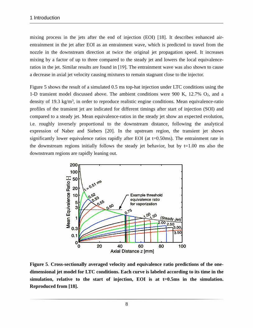
mixing process in the jets after the end of injection (EOI) [18]. It describes enhanced air-entrainment in the jet after EOI as an entrainment wave, which is predicted to travel from the nozzle in the downstream direction at twice the original jet propagation speed. It increases mixing by a factor of up to three compared to the steady jet and lowers the local equivalence-ratios in the jet. Similar results are found in [19]. The entrainment wave was also shown to cause a decrease in axial jet velocity causing mixtures to remain stagnant close to the injector.
Figure 5 shows the result of a simulated 0.5 ms top-hat injection under LTC conditions using the 1-D transient model discussed above. The ambient conditions were 900 K, 12.7% O2, and a density of 19.3 kg/m3, in order to reproduce realistic engine conditions. Mean equivalence-ratio profiles of the transient jet are indicated for different timings after start of injection (SOI) and compared to a steady jet. Mean equivalence-ratios in the steady jet show an expected evolution, i.e. roughly inversely proportional to the downstream distance, following the analytical expression of Naber and Siebers [20]. In the upstream region, the transient jet shows significantly lower equivalence ratios rapidly after EOI (at t=0.50ms). The entrainment rate in the downstream regions initially follows the steady jet behavior, but by t=1.00 ms also the downstream regions are rapidly leaning out.
Figure 5. Cross-sectionally averaged velocity and equivalence ratio predictions of the one-dimensional jet model for LTC conditions. Each curve is labeled according to its time in the simulation, relative to the start of injection, EOI is at t=0.5ms in the simulation. Reproduced from [18].
1 Introduction
8
A threshold equivalence ratio for vaporization is indicated in the figure at a mean equivalence ratio of 2.5. It can be seen that no liquid fuel is left in the jet after t=0.60 ms in the simulation, as a consequence of the enhanced mixing. In a similar way, an equivalence ratio threshold for ignition or complete combustion lies around 0.5 for diesel fuel. The figure clearly shows that mixtures in the upstream region quickly fall below this value after EOI. A large part of the jet is over-mixed by t=1.50ms.
1.3 Challenges of combustion in diesel engines
Emissions legislations
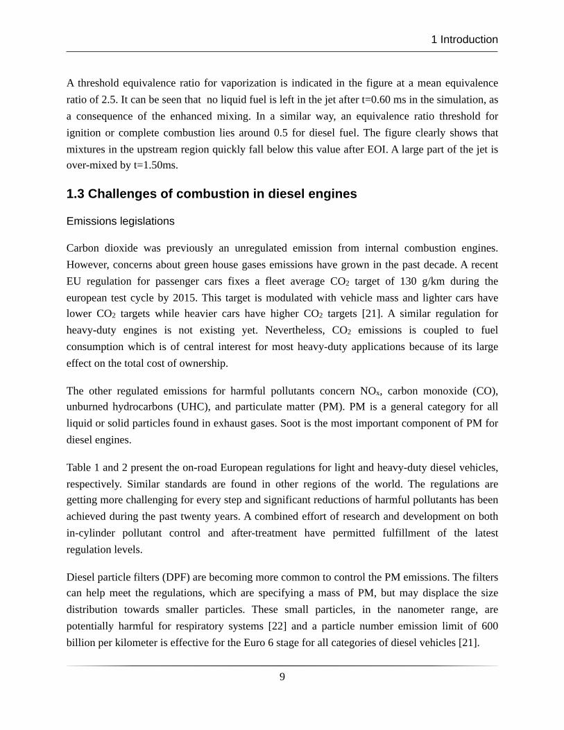
Carbon dioxide was previously an unregulated emission from internal combustion engines. However, concerns about green house gases emissions have grown in the past decade. A recent EU regulation for passenger cars fixes a fleet average CO2 target of 130 g/km during the european test cycle by 2015. This target is modulated with vehicle mass and lighter cars have lower CO2 targets while heavier cars have higher CO2 targets [21]. A similar regulation for heavy-duty engines is not existing yet. Nevertheless, CO2 emissions is coupled to fuel consumption which is of central interest for most heavy-duty applications because of its large effect on the total cost of ownership.
The other regulated emissions for harmful pollutants concern NOx, carbon monoxide (CO), unburned hydrocarbons (UHC), and particulate matter (PM). PM is a general category for all liquid or solid particles found in exhaust gases. Soot is the most important component of PM for diesel engines.
Table 1 and 2 present the on-road European regulations for light and heavy-duty diesel vehicles, respectively. Similar standards are found in other regions of the world. The regulations are getting more challenging for every step and significant reductions of harmful pollutants has been achieved during the past twenty years. A combined effort of research and development on both in-cylinder pollutant control and after-treatment have permitted fulfillment of the latest regulation levels.
Diesel particle filters (DPF) are becoming more common to control the PM emissions. The filters can help meet the regulations, which are specifying a mass of PM, but may displace the size distribution towards smaller particles. These small particles, in the nanometer range, are potentially harmful for respiratory systems [22] and a particle number emission limit of 600 billion per kilometer is effective for the Euro 6 stage for all categories of diesel vehicles [21].
1 Introduction
9
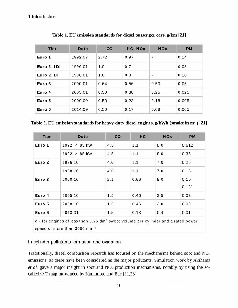
Table 1. EU emission standards for diesel passenger cars, g/km [21]
Tier Date CO HC+NOx NOx PM
Euro 1 1992.07 2.72 0.97 - 0.14
Euro 2, IDI 1996.01 1.0 0.7 - 0.08
Euro 2, DI 1996.01 1.0 0.9 - 0.10
Euro 3 2000.01 0.64 0.56 0.50 0.05
Euro 4 2005.01 0.50 0.30 0.25 0.025
Euro 5 2009.09 0.50 0.23 0.18 0.005
Euro 6 2014.09 0.50 0.17 0.08 0.005
Table 2. EU emission standards for heavy-duty diesel engines, g/kWh (smoke in m-1) [21]
Tier Date CO HC NOx PM
Euro 1 1992, < 85 kW 4.5 1.1 8.0 0.612
1992, > 85 kW 4.5 1.1 8.0 0.36
Euro 2 1996.10 4.0 1.1 7.0 0.25
1998.10 4.0 1.1 7.0 0.15
Euro 3 2000.10 2.1 0.66 5.0 0.10
0.13a
Euro 4 2005.10 1.5 0.46 3.5 0.02
Euro 5 2008.10 1.5 0.46 2.0 0.02
Euro 6 2013.01 1.5 0.13 0.4 0.01
a - for engine
speed of mor
es of less than 0.75 dm
re than 3000 min-1
m3 swept volumme per cylindder and a rateed power
In-cylinder pollutants formation and oxidation
Traditionally, diesel combustion research has focused on the mechanisms behind soot and NOx emissions, as these have been considered as the major pollutants. Simulation work by Akihama et al. gave a major insight in soot and NOx production mechanisms, notably by using the so-called Φ-T map introduced by Kamimoto and Bae [11,23].
1 Introduction
10
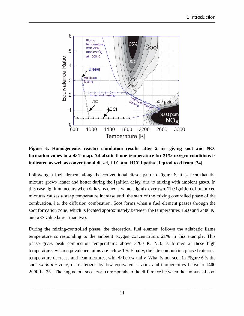
Figure 6. Homogeneous reactor simulation results after 2 ms giving soot and NOx formation zones in a Φ-T map. Adiabatic flame temperature for 21% oxygen conditions is indicated as well as conventional diesel, LTC and HCCI paths. Reproduced from [24]
Following a fuel element along the conventional diesel path in Figure 6, it is seen that the mixture grows leaner and hotter during the ignition delay, due to mixing with ambient gases. In this case, ignition occurs when Φ has reached a value slightly over two. The ignition of premixed mixtures causes a steep temperature increase until the start of the mixing controlled phase of the combustion, i.e. the diffusion combustion. Soot forms when a fuel element passes through the soot formation zone, which is located approximately between the temperatures 1600 and 2400 K, and a Φ-value larger than two.
During the mixing-controlled phase, the theoretical fuel element follows the adiabatic flame temperature corresponding to the ambient oxygen concentration, 21% in this example. This phase gives peak combustion temperatures above 2200 K. NOx is formed at these high temperatures when equivalence ratios are below 1.5. Finally, the late combustion phase features a temperature decrease and lean mixtures, with Φ below unity. What is not seen in Figure 6 is the soot oxidation zone, characterized by low equivalence ratios and temperatures between 1400 2000 K [25]. The engine out soot level corresponds to the difference between the amount of soot
1 Introduction
11
formed and oxidized. Engine-out soot emissions can thereby be decreased both by reducing soot formation and enhancing oxidation.
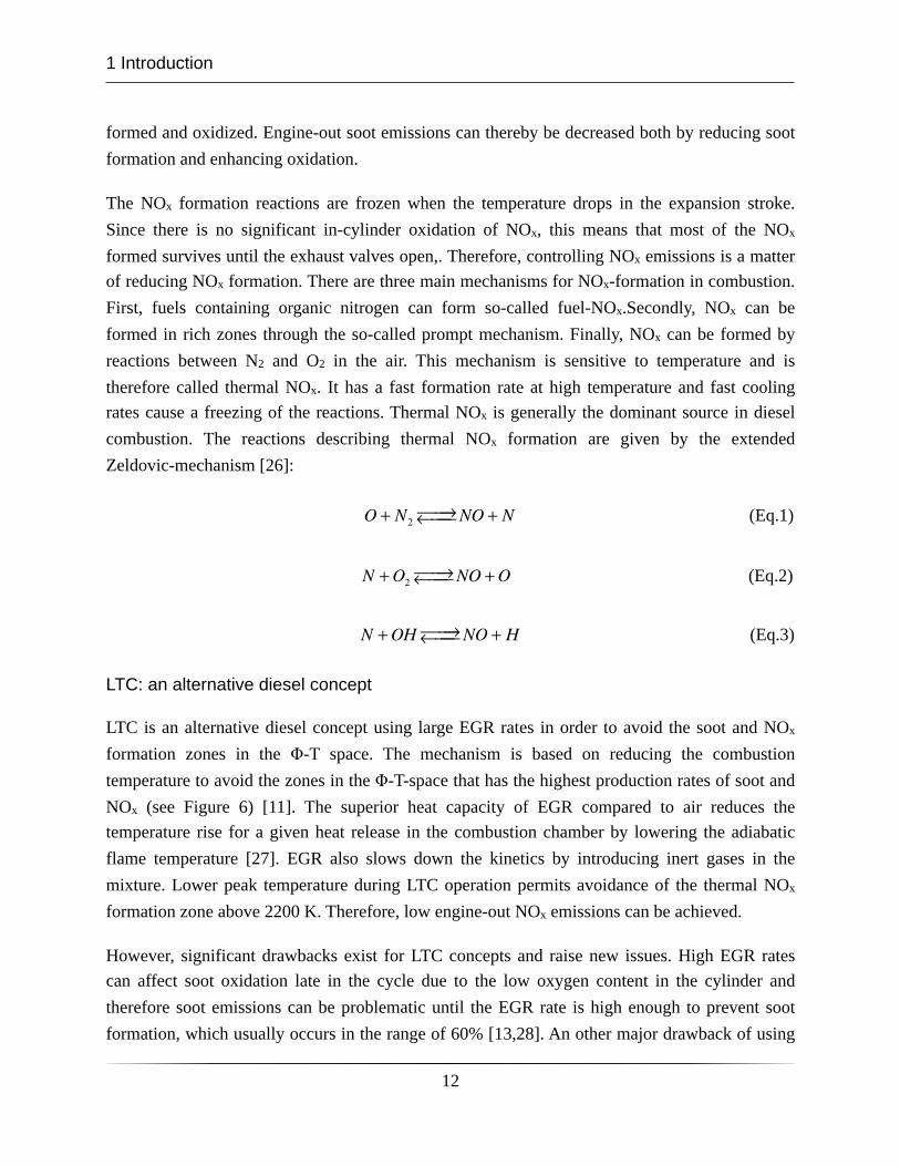
The NOx formation reactions are frozen when the temperature drops in the expansion stroke. Since there is no significant in-cylinder oxidation of NOx, this means that most of the NOx formed survives until the exhaust valves open,. Therefore, controlling NOx emissions is a matter of reducing NOx formation. There are three main mechanisms for NOx-formation in combustion. First, fuels containing organic nitrogen can form so-called fuel-NOx.Secondly, NOx can be formed in rich zones through the so-called prompt mechanism. Finally, NOx can be formed by reactions between N2 and O2 in the air. This mechanism is sensitive to temperature and is therefore called thermal NOx. It has a fast formation rate at high temperature and fast cooling rates cause a freezing of the reactions. Thermal NOx is generally the dominant source in diesel combustion. The reactions describing thermal NOx formation are given by the extended Zeldovic-mechanism [26]:
O + N2⎯→⎯←⎯⎯ NO + N (Eq.1)
N +O2⎯→⎯←⎯⎯ NO +O (Eq.2)
N +OH ⎯→⎯←⎯⎯ NO + H (Eq.3)
LTC: an alternative diesel concept
LTC is an alternative diesel concept using large EGR rates in order to avoid the soot and NOx formation zones in the Φ-T space. The mechanism is based on reducing the combustion temperature to avoid the zones in the Φ-T-space that has the highest production rates of soot and NOx (see Figure 6) [11]. The superior heat capacity of EGR compared to air reduces the temperature rise for a given heat release in the combustion chamber by lowering the adiabatic flame temperature [27]. EGR also slows down the kinetics by introducing inert gases in the mixture. Lower peak temperature during LTC operation permits avoidance of the thermal NOx formation zone above 2200 K. Therefore, low engine-out NOx emissions can be achieved.
However, significant drawbacks exist for LTC concepts and raise new issues. High EGR rates can affect soot oxidation late in the cycle due to the low oxygen content in the cylinder and therefore soot emissions can be problematic until the EGR rate is high enough to prevent soot formation, which usually occurs in the range of 60% [13,28]. An other major drawback of using
1 Introduction
12
higher EGR-rates is the elevated levels of CO and UHC emissions that are not problematic in conventional diesel cases using low dilution rates.
Over-lean mixtures can be formed in some regions due to the slow reaction rates at lower combustion temperatures [29]. A local equivalence ratio below the ignitability limit, approximately Φ=0.5, causes non-complete oxidation of the fuel and will cause CO and UHC emissions. However, both CO and UHC can originate from rich mixtures as well [30]. The increase in these emissions caused by partially oxidized fuel during the combustion process has an impact on combustion efficiency which is further disadvantage.
LTC and other similar partially premixed diesel concepts are currently being investigated to further understand and minimize the drawbacks of these concepts while taking advantage of the low soot and NOx emissions achievable.
Cold starting issues
Cold start at very low ambient temperatures is another important and challenging aspect of diesel engine development. At ambient temperatures down to -25 °C it is difficult to auto-ignite the charge. Cold starting represents only a minor part of the engine utilization, but demands on cold starting performance may still compromise the development of other aspects of the engine.
There is a general trend towards lower compression ratios. This is due to ever higher specific powers [31] and more stringent emission legislations, especially for NOx. This trend poses even greater challenges for cold start performance, as lower compression ratios mean lower pressure and temperature levels in the cylinder at start of injection (SOI). This leads to fuel evaporation issues. It has been demonstrated that as much as 80% of the injected fuel mass does not burn during a cycle at 273 K conditions [32]. Most of it adheres to the cold surfaces and is difficult to vaporize.
A typical cold start for light-duty diesel engines is presented in Figure 7 and can be divided into five phases. First, the glowplug is glowing during a given period, here 10 seconds. After this, the starter motor is activated and the engine is cranked up to 200 rpm until the combustion takes over. Cranking time is longer at lower temperatures. At engine start an engine speed overshoot is typically observed. It is due to a steep load increase during the first combustion cycles. Load can be in the range of 8-11 bar IMEP in this third phase. The engine speed is then unstable for a limited period of time where load and combustion phasing variations are large. The last phase commences when engine speed stabilizes at the nominal idle speed.
1 Introduction
13
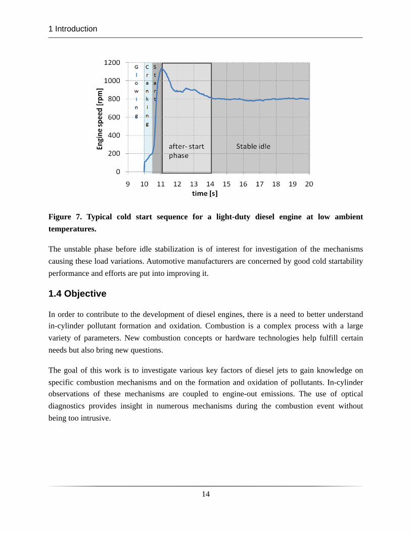
Figure 7. Typical cold start sequence for a light-duty diesel engine at low ambient temperatures.
The unstable phase before idle stabilization is of interest for investigation of the mechanisms causing these load variations. Automotive manufacturers are concerned by good cold startability performance and efforts are put into improving it.
1.4 Objective
In order to contribute to the development of diesel engines, there is a need to better understand in-cylinder pollutant formation and oxidation. Combustion is a complex process with a large variety of parameters. New combustion concepts or hardware technologies help fulfill certain needs but also bring new questions.
The goal of this work is to investigate various key factors of diesel jets to gain knowledge on specific combustion mechanisms and on the formation and oxidation of pollutants. In-cylinder observations of these mechanisms are coupled to engine-out emissions. The use of optical diagnostics provides insight in numerous mechanisms during the combustion event without being too intrusive.
1 Introduction
14
2 Optical engines and diagnostics
2.1 Design of Bowditch-type optical engines
Optical engines allow visual access to the combustion chamber and are valuable tools for combustion diagnostics. As a complement to combustion vessels, where fundamental combustion studies can be conducted, optical engines provide a realistic engine environment for combustion investigations. The optical access, usually on one of the cylinders only, is made by exchanging some metal parts of the combustion chamber with transparent material, often made in quartz. Different optical engine designs exist. Some have only access to the combustion chamber via an endoscope, which enables high load operation but limits the optical access. The design proposed by Bowditch is commonly used in optical engine research. It provides better optical access but is operable in a more limited load range. [33]
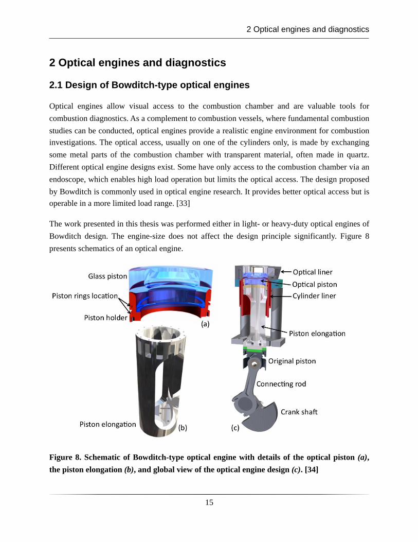
The work presented in this thesis was performed either in light- or heavy-duty optical engines of Bowditch design. The engine-size does not affect the design principle significantly. Figure 8 presents schematics of an optical engine.
Figure 8. Schematic of Bowditch-type optical engine with details of the optical piston (a), the piston elongation (b), and global view of the optical engine design (c). [34]
2 Optical engines and diagnostics
15
The lower part of the engine is not modified. A hollow piston elongation (b) is fixed on the original piston and an optical piston (a) is mounted on top of the elongation. Since only one of the cylinders is modified for optical studies, the others are drilled-through to prevent compression work and a mass of tungsten is added on top of them to compensate for the mass increase of the optical piston and prevent vibrations.
The optical access from under the piston is obtained with a 45° mirror, not represented in the schematics, mounted fixed on the engine block inside the hollow piston elongation. Furthermore, a liner of quartz, or of metal with quartz windows, is mounted under the firedeck to permit optical access to the combustion chamber from the side. It enables viewing from the side but it is often used as optical path for lasers when using laser-diagnostics. As a consequence of this optical liner design, the piston rings have to be mounted low on the optical piston crown in order not to pass over the junction between the main liner and the optical liner, see (a) in Figure 8.
The piston glass can be made in various shapes and it is possible to replicate the original piston bowl geometry. However complex curved geometries introduce optical distortions to the data that need to be corrected with specific algorithms. Furthermore, sharp edges like in the case of a reentrant bowl can cause very high local thermal stresses and may cause failure of the piston.
2.2 Limitations of optical engines
Optical engines of Bowditch type enable combustion studies with optical diagnostics in realistic conditions with a comfortable optical access. Even though optical engines are a key element in gaining knowledge on real life combustion mechanisms, the limitations of these engines are not negligible and must be taken into account when designing experiments.
The most obvious limitation of this type of optical engines is the load capability of the design. Optical parts made in quartz are not able to cope with high peak pressures and high pressure derivatives may be even more problematic. Therefore, mostly low to medium load cases can be studied in the test engines of this work. As mentioned previously, stronger designs that only have endoscopic access may resist full load operation, but this is at the expense of the optical access.
An important aspect of studies in optical engines is to reflect the conditions of an ordinary metal engine in order to maintain the relevance of the investigations. Research has shown that the low heat conductivity of quartz compared to aluminum could affect the wall temperature in the cylinder and, as a consequence, influence the combustion process [35]. A skip fire routine can be adopted to avoid these issues and achieve the same wall temperature for the quartz and
2 Optical engines and diagnostics
16
aluminum pistons. Furthermore, given the less efficient cooling system of the optical combustion chamber compared to a metal engine, skip fire operation modes help limiting the thermal load of the engine.
Furthermore, the in-cylinder conditions at TDC are essential parameters for combustion processes. The compression ratio is a key element to reproduce the same condition as in a metal engine. However, in order to avoid contact between the piston and the valves with a safe margin, the squish height of optical engines is usually increased compared to metal engines. A second major difference is the low position of the piston rings, see Figure 8, which creates a larger ring land volume than the original piston design. As a result, boost pressure has to be adjusted to simulate the original compression ratio and density at top dead center. A recent study [36] has shown the deformation of various engine parts due to gas forces around compression TDC. It was brought to light that in some cases, the squish height is largely increased and influences the theoretical volume calculations as well as the spray targeting in the piston bowl. An important conclusion of this study is that half of the squish heigh increase is caused by compression of the original piston and connecting-rod assembly.
Research has been conducted to identify the differences between all-metal and optical engines in terms of combustion characteristics [37,38]. It was found that the use of optical parts affect the combustion process. The effects can be seen both in the heat release and in the exhaust emissions. They are explained by the poor heat conductivity of quartz compared to steel or aluminum. The presence of optical parts can, however, be compensated for. It was shown that the influence could be eliminated if the inlet temperature was lowered. This resulted in the same heat release rates, regarding both phasing and shape, as well as the same exhaust emissions for the metal and optical engines.
A specific issue with single cylinder operation, even more when skip fire routines are employed, is the usage of exhaust gas recirculation. The exhaust gas flow of the engine in such conditions is pulsating and not suitable for controlled dilution of the inlet charge. In the main test facility used during this thesis, exhaust gases are generated by an external diesel furnace working at stoichiometric conditions. These exhaust gases are in theory free from air, unburned fuel, and particles. They also provide a realistic substitute for EGR.
Finally, investigation of diesel combustion through transparent parts in contact with combustion raises window fouling issues. Under some conditions only a few combustion cycles can be performed before cleaning is necessary. The deposit on the surfaces, mostly soot, causes
2 Optical engines and diagnostics
17
attenuation of the signals recorded and can introduce measurement errors. Some diagnostics are providing a low signal level to start with and attenuation becomes an even larger issue in these case.
2.3 Conventional diagnostics for combustion investigations
Heat release and temperature calculations
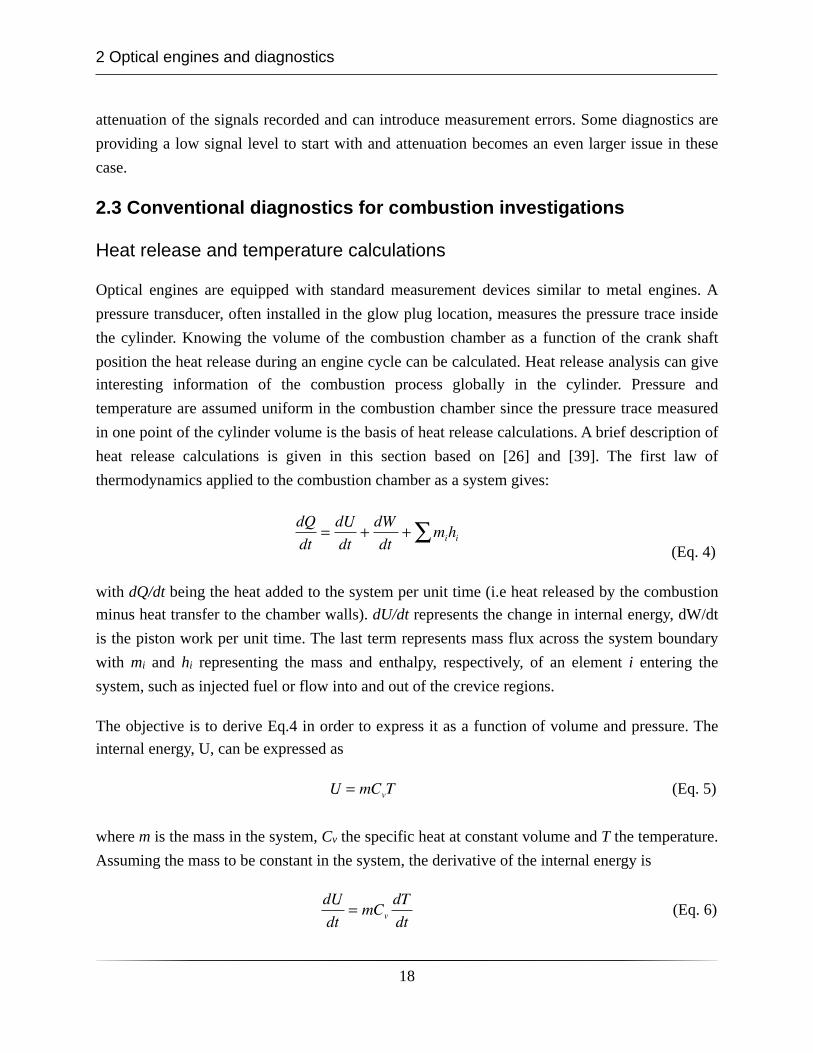
Optical engines are equipped with standard measurement devices similar to metal engines. A pressure transducer, often installed in the glow plug location, measures the pressure trace inside the cylinder. Knowing the volume of the combustion chamber as a function of the crank shaft position the heat release during an engine cycle can be calculated. Heat release analysis can give interesting information of the combustion process globally in the cylinder. Pressure and temperature are assumed uniform in the combustion chamber since the pressure trace measured in one point of the cylinder volume is the basis of heat release calculations. A brief description of heat release calculations is given in this section based on [26] and [39]. The first law of thermodynamics applied to the combustion chamber as a system gives:
dQ
dt=dU
dt+dW
dt+ mihi∑
(Eq. 4)
with dQ/dt being the heat added to the system per unit time (i.e heat released by the combustion minus heat transfer to the chamber walls). dU/dt represents the change in internal energy, dW/dt is the piston work per unit time. The last term represents mass flux across the system boundary with mi and hi representing the mass and enthalpy, respectively, of an element i entering the system, such as injected fuel or flow into and out of the crevice regions.
The objective is to derive Eq.4 in order to express it as a function of volume and pressure. The internal energy, U, can be expressed as
U = mCvT (Eq. 5)
where m is the mass in the system, Cv the specific heat at constant volume and T the temperature. Assuming the mass to be constant in the system, the derivative of the internal energy is
dU
dt= mCv
dT
dt (Eq. 6)
2 Optical engines and diagnostics
18

In order to express the temperature derivative with known parameters, the ideal gas law is employed. Likewise, the global temperature (i.e. for both burned and unburned gases) can be obtained by applying the ideal gas law to the pressure data acquired,
pV = mRT (Eq. 7)
Neglecting mass losses and considering R to be constant, the internal energy of the system per unit time can now be expressed as
dU
dt=Cv
RpdV
dt+V
dp
dt⎛⎝⎜
⎞⎠⎟
(Eq. 8)
The second factor in Eq.4, the work performed on the piston, can be written as a function of cylinder pressure p and volume V as
dW
dt= p
dV
dt (Eq. 9)
Neglecting mass exchange and inserting Eq.8 and Eq.9 in the expression for heat release (Eq.4) we obtain
dQ
dt=Cv
RpdV
dt+V
dp
dt⎛⎝⎜
⎞⎠⎟+ p
dV
dt (Eq. 10)
Making the assumption of an ideal gas, the constant R can be expressed as a function of the specific heats at constant pressure and volume:
R = Cp − Cv (Eq. 11)
The ratio of specific heats, γ, is given by
γ =Cp
Cv
(Eq. 12)
2 Optical engines and diagnostics
19
Then, the first right hand term of Eq.10 can be expressed:
Cv
R=
1
γ −1 (Eq. 13)
Eq.10 can be written as follows:
dQ
dt=
γγ −1
pdV
dt+
1
γ −1Vdp
dt (Eq. 14)
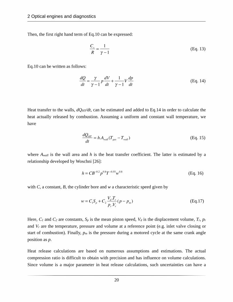
Heat transfer to the walls, dQHT/dt, can be estimated and added to Eq.14 in order to calculate the heat actually released by combustion. Assuming a uniform and constant wall temperature, we have
dQHT
dt= h.Awall (Tgas − Twall ) (Eq. 15)
where Awall is the wall area and h is the heat transfer coefficient. The latter is estimated by a relationship developed by Woschni [26]:
h = CB−0.2 p0.8T −0.55w0.8 (Eq. 16)
with C, a constant, B, the cylinder bore and w a characteristic speed given by
w = C1Sp + C2
Vd .Trpr .Vr
(p − pm ) (Eq.17)
Here, C1 and C2 are constants, Sp is the mean piston speed, Vd is the displacement volume, Tr, pr and Vr are the temperature, pressure and volume at a reference point (e.g. inlet valve closing or start of combustion). Finally, pm is the pressure during a motored cycle at the same crank angle position as p.
Heat release calculations are based on numerous assumptions and estimations. The actual compression ratio is difficult to obtain with precision and has influence on volume calculations. Since volume is a major parameter in heat release calculations, such uncertainties can have a
2 Optical engines and diagnostics
20
large impact on the heat release analysis. Furthermore, the ratio of specific heats, γ, is often estimated for a given gas composition and temperature during the inlet stroke. Compression and combustion will change these parameters and thereby the actual value of γ during the engine cycle. Moreover, the volume calculations are based on geometrical data, in reality the engine geometry can be changing due to temperature of the materials and gas pressure effects on the several engine parts such as piston and connecting rod. Finally, the exact synchronization between the pressure and volume traces is of major importance for heat release calculations and can introduce large errors if it is not correct.
Emission measurements
The analysis of exhaust gases is an important aspect of engine investigations in the scope of this thesis. For many studies, the optical diagnostics results are correlated to exhaust emissions in order to understand the underlying processes of in-cylinder pollutant formation better. Here follows a brief description of the measurement techniques used to measure the engine-out emissions that are investigated in this thesis, i.e. unburned hydrocarbons and smoke.
Exhaust gases are ideally sampled close to the cylinder head in the exhaust pipe and pumped to the measurement devices through a heated line in order to avoid condensation of the hot exhaust gases. Condensation along the way would affect the measured concentration of the different substances of interest.
Unburned hydrocarbons are detected with a flame ionization detector (FID). Combustion of hydrocarbons forms electrons and positive ions. Therefore, by burning unburned hydrocarbons in an electric field formed by two electrodes, a measurable current flow is obtained and corresponds to the number of carbon atoms present. FIDs usually use a hydrogen-helium-air flame between the electrodes since it does not cause any ionization that would interfere with the measurements. Calibration of the instrument is necessary to assure accuracy of the obtained values. At first, pure nitrogen is pumped in the FID to zero the output value. Then, a calibration gas with a known UHC concentration is used and the value obtained is adjusted if necessary.[40]
Smoke level is most often measured with a filter method. A sample volume of exhaust gas is drawn through a white filter paper. The reflection of the darkened filter is then measured with a light source and compared to the original reflection of the paper. A filtered smoke number (FSN) is then obtained in the range 0, unaltered reflection, and 10, zero reflection. [40]. The FSN values can be related to more practical soot concentration values in the exhaust gases. [40,41]
2 Optical engines and diagnostics
21
2.4 Optical diagnostics for combustion investigations
Passive optical diagnostics
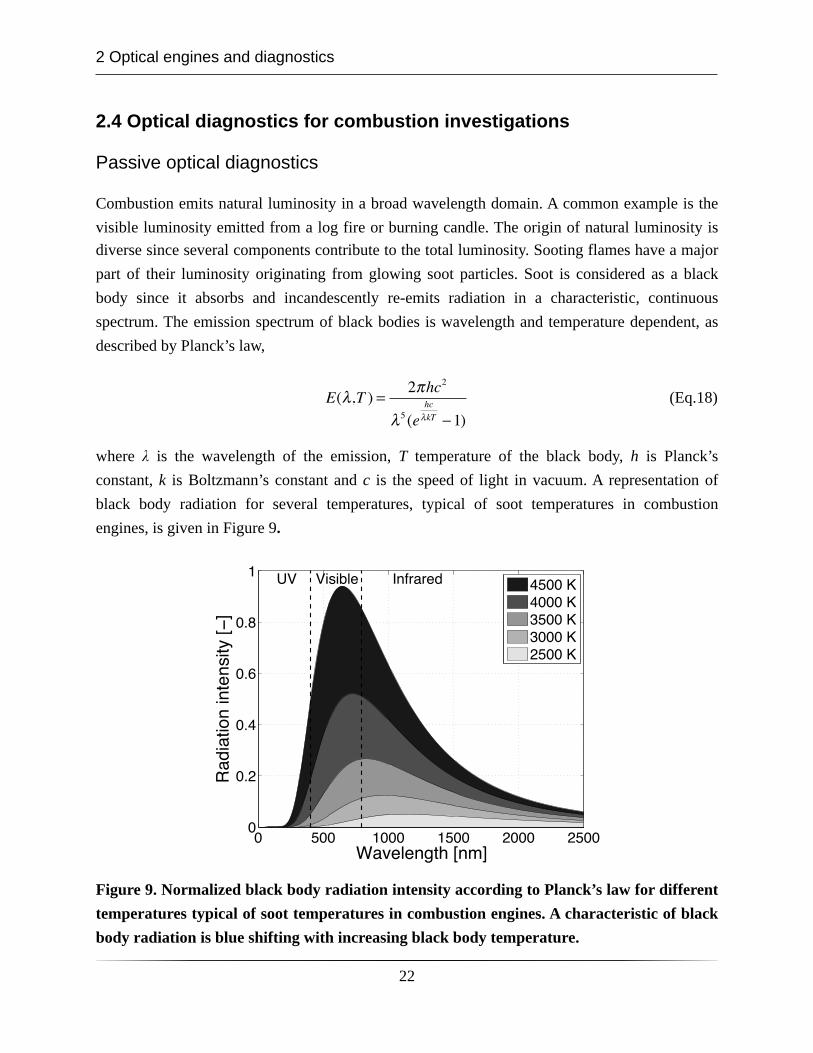
Combustion emits natural luminosity in a broad wavelength domain. A common example is the visible luminosity emitted from a log fire or burning candle. The origin of natural luminosity is diverse since several components contribute to the total luminosity. Sooting flames have a major part of their luminosity originating from glowing soot particles. Soot is considered as a black body since it absorbs and incandescently re-emits radiation in a characteristic, continuous spectrum. The emission spectrum of black bodies is wavelength and temperature dependent, as described by Planck’s law,
E(λ,T ) = 2πhc2
λ5 (ehc
λkT −1) (Eq.18)
where λ is the wavelength of the emission, T temperature of the black body, h is Planck’s constant, k is Boltzmann’s constant and c is the speed of light in vacuum. A representation of black body radiation for several temperatures, typical of soot temperatures in combustion engines, is given in Figure 9.
Figure 9. Normalized black body radiation intensity according to Planck’s law for different temperatures typical of soot temperatures in combustion engines. A characteristic of black body radiation is blue shifting with increasing black body temperature.
2 Optical engines and diagnostics
22
The radiation intensity profile is broadband and its peak value is blue shifted , i.e. shifted towards shorter wavelengths, when the black body temperature increases. Furthermore, the peak intensity is significantly increasing with temperature. Therefore, black bodies appear to be black at ambient temperatures due to the low radiation intensity and shift towards blue color at higher temperature.
Given the broadband nature of black body radiation, and the fact that peak values are in the visible wavelength domain for combustion relevant temperatures, capturing soot luminosity can be done with a regular visible detector and a glass lens. A global estimation of soot luminosity during the combustion event can also be performed with photodiodes and filters for specific wavelengths.
Natural luminosity from soot is an important aspect in optical diagnostics of diesel combustion. However, other radiations, like chemiluminescence from excited radicals, are naturally emitted during combustion. A radical of major interest for chemiluminescence measurements of diesel combustion is the hydroxyl radical (OH). It indicates regions of high temperature and stoichiometric combustion [42,43]. The high temperature reactions produce a significant amount of the excited state of OH (OH*). The chemiluminescence emitted from OH* returning to its ground state gives a banded spectrum, unlike the broadband, continuous spectrum of soot mentioned previously. This banded spectrum has one of its strongest peaks near 310 nm [44,45]. A band pass filter centered around this wavelength can be employed to capture the distribution of OH on a UV sensitive camera.
Interferences from soot luminosity in the acquired OH-chemiluminescence signal can be an issue. Due to its broadband nature, natural luminescence from soot can be transmitted through a narrowband UV interference filter. This concern is greater at higher soot temperatures since radiation in the UV region becomes stronger. Care must be taken to avoid misinterpreting the data, especially for highly sooting cases. To avoid this problem, a camera equipped with a stereoscope can be used with an interference filter on one entrance and a neutral density filter on the other. This setup produces two simultaneous images of the combustion process that can be used to distinguish the much weaker OH-chemiluminescence from soot luminosity.
Since no light source is employed for natural luminosity measurements, the signal is obtained from the integrated line of sight. For instance, this means that signal is acquired from the whole volume of a jet. This is another aspect to take into account when drawing conclusions from data obtained by these passive diagnostics.
2 Optical engines and diagnostics
23
The temperature dependance and the line of sight aspect of these measurement techniques are significant limitations. However, this type of diagnostic is a very useful tool for numerous diesel jet investigations, for example lift-off length determination.
Laser-based diagnostics
Laser diagnostics are more detailed and complex measurement techniques compared to the natural luminescence measurements. These active optical measurement techniques use external radiation sources, to generate signal from given species in a finite measurement volume. This volume can be a point, a line , a plane or a three dimensional region. Therefore, the line of sight aspect of the diagnostic is generally not an issue. Pulsed lasers, which are common in laser diagnostics, makes it possible to obtain a frozen picture of a transient combustion process. They also give the possibility of high time resolution in the measurements. Two laser-based optical diagnostics will be presented in this section, laser induced incandescence and laser induced fluorescence, since they have been used in the work of this thesis.
Laser induced incandescence (LII) is a commonly used diagnostic technique aimed at visualizing soot volume fraction [46,47]. LII is created by a laser pulse heating particles to a temperature significantly higher than the surrounding medium. The upper limit of the soot particle temperature is ~4000 K. Above this temperature sublimation of small molecules (e.g. C2 and C3) from the soot particles prohibits further temperature increase. Since the laser heated soot particles are much hotter than the surrounding gas their emitted light spectra are blue shifted compared to the surrounding cooler particles. The blue shifted light is collected as the LII signal, usually at short wavelengths where the flame background luminosity is insignificant, since the black body radiation of soot particles is temperature dependent. [42]. A short camera gate is usually a way to get rid of background luminosity when collecting LII signal.
Controlling the level of the background luminosity is not the only concern for LII signal collection. The laser radiation used to heat up soot particles can have the side-effect of exciting certain molecules, causing laser-induced fluorescence (LIF) as they relax to their ground state. Interferences from LIF can be collected together with the LII signal, due to wavelength and intensity similarities of the signals, and lead to misinterpretation of the soot concentration. LII can be performed with a Nd:YAG laser at 1064 or 532 nm but the latter has been seen to cause LIF of poly-aromatic hydrocarbons in highly diluted conditions [48] and therefore 1064 nm can be preferred to avoid interferences.
2 Optical engines and diagnostics
24
Furthermore, LII signal can be affected in highly sooting combustion environments by two major problems: the extinction of the laser sheet by the soot particles and the attenuation, or trapping, of the signal while propagating from the measurement plane to the detector. Both of these effects are spatially inhomogeneous and, therefore difficult to compensate for. However, improvements can be made for extinction problems by adjusting the fluence of the laser, i.e. the laser pulse energy divided by the cross section of the laser sheet. The LII signal is typically proportional to the laser fluence. A higher fluence yields a higher LII signal since soot particle temperatures become higher. This dependence on the fluence is the reason for extinction issues and can be suppressed if the laser fluence becomes high enough. Sublimation of soot particles then reduce the signal strength at the same rate as the increased fluence increases it. As a result the LII signal intensity becomes independent of the laser fluence. This regime is called the fluence plateau. Therefore, despite laser extinction by soot particles along the path of the laser sheet, LII can remain on the fluence plateau and provide an unaffected signal intensity.
Planar laser induced fluorescence (PLIF) imaging is a diagnostic technique for measuring distributions and potentially concentrations of species in the combustion process. A laser is used to excite given molecules which then spontaneously relax from their excited state to their ground state. Photons are emitted during the relaxation process and the wavelength of this fluorescence corresponds to the distance between the excited and relaxed energy levels. Usually fluorescence takes place at longer wavelength than the excitation wavelength. For example, OH-PLIF is often excited at 284 nm and signal is collected around 310 nm with appropriate filtering.
Excitation and fluorescence wavelengths are specific for a given molecule although overlapping absorption spectra is possible. For example, in some cases like 355 nm excitation LIF, the fluorescence signal is likely to originate from several molecules present during combustion, e.g. formaldehyde and poly-aromatic hydrocarbons since they all can be excited by the 355 nm laser light. In such cases, a spectrograph can be used in addition to the LIF capturing camera to spectrally differentiate the species. The very specific spectral fingerprint of the formaldehyde band spectrum between 380 and 450 nm is used to extract formaldehyde-LIF signal from the broadband PAH-LIF signal.
2 Optical engines and diagnostics
25
3 Results and discussion
3.1 Cold start
As mentioned in the introduction section, the trend in the development of diesel engines goes towards lower compression ratios in order to achieve low NOx emissions and to comply with stringent legislations. A consequence is lower compression temperatures in the cylinder by the start of injection. This aspect becomes an issue when starting at low or very low ambient temperatures (-20°C) since evaporation and auto-ignition of the diesel jets are dependent of the compressed temperature in the cylinder.
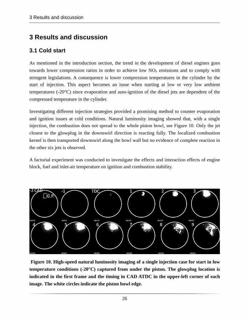
Investigating different injection strategies provided a promising method to counter evaporation and ignition issues at cold conditions. Natural luminosity imaging showed that, with a single injection, the combustion does not spread to the whole piston bowl, see Figure 10. Only the jet closest to the glowplug in the downswirl direction is reacting fully. The localized combustion kernel is then transported downswirl along the bowl wall but no evidence of complete reaction in the other six jets is observed.
A factorial experiment was conducted to investigate the effects and interaction effects of engine block, fuel and inlet-air temperature on ignition and combustion stability.
Figure 10. High-speed natural luminosity imaging of a single injection case for start in low temperature conditions (-20°C) captured from under the piston. The glowplug location is indicated in the first frame and the timing in CAD ATDC in the upper-left corner of each image. The white circles indicate the piston bowl edge.
3 Results and discussion
26
Engine block temperature was found to be the most significant parameter for cold start optimization, both in terms of load achieved for a given injected fuel mass and of combustion phasing. Inlet air temperature was shown to be the second most significant factor, especially affecting load stability. However, it is clear that the influence of the engine block temperature on the inlet air temperature is not negligible. Heat transfer between the cylinder head and the inlet air can influence the real origin of the observed effects.
Fuel temperature at the high-pressure pump inlet was found to be a less significant factor for most responses. Similarly to the limitation mentioned above, the actual temperature of the injected fuel can be influenced due to heat transfer in the injection system. A detailed investigation of in-cylinder inlet air and injected fuel temperature would help studying the problem with more accuracy.
The relative position of the glow-plug and the nearest spray revealed that increasing the angle can improve combustion phasing stability and reduce the pressure derivative, i.e. combustion noise.
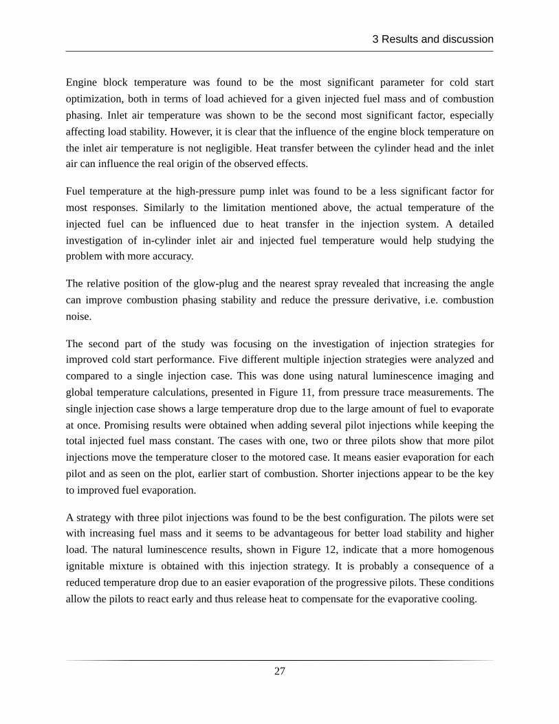
The second part of the study was focusing on the investigation of injection strategies for improved cold start performance. Five different multiple injection strategies were analyzed and compared to a single injection case. This was done using natural luminescence imaging and global temperature calculations, presented in Figure 11, from pressure trace measurements. The single injection case shows a large temperature drop due to the large amount of fuel to evaporate at once. Promising results were obtained when adding several pilot injections while keeping the total injected fuel mass constant. The cases with one, two or three pilots show that more pilot injections move the temperature closer to the motored case. It means easier evaporation for each pilot and as seen on the plot, earlier start of combustion. Shorter injections appear to be the key to improved fuel evaporation.
A strategy with three pilot injections was found to be the best configuration. The pilots were set with increasing fuel mass and it seems to be advantageous for better load stability and higher load. The natural luminescence results, shown in Figure 12, indicate that a more homogenous ignitable mixture is obtained with this injection strategy. It is probably a consequence of a reduced temperature drop due to an easier evaporation of the progressive pilots. These conditions allow the pilots to react early and thus release heat to compensate for the evaporative cooling.
3 Results and discussion
27
Figure 11. Global in-cylinder temperature calculated from the pressure data for different injection strategies during cold start conditions.
This study of cold starting at low ambient temperature in an optical diesel engine was one of the first of this kind. Investigations of cold start during realistic conditions in optical engines are rare and few studies were found in the literature [49,50,51]. The unique aspects of the present study are the optical investigation of advanced injection strategies, their effects on after-start stability and the separation of the effects of engine block, fuel, and inlet air temperatures on after start stability.
Many technical issues were brought to light during the preliminary tests and specific procedures were progressively defined to assure the repeatability and quality of the measurements. Based on the technical knowledge acquired during this investigation, more specific diagnostics could be employed to explore cold starting and multiple injection strategies more in detail in future investigations. Mie scattering measurements on the liquid portion of the jets could for example give insight in the wall-impingement and evaporation issues at low temperatures. Furthermore, 355 nm PLIF together with OH-PLIF could help characterize the zones were first and second stage ignition occur. Spectral analysis of the 355 nm PLIF signal would be suggested in order to differentiate formaldehyde from PAH in the fluorescence signal.
3 Results and discussion
28
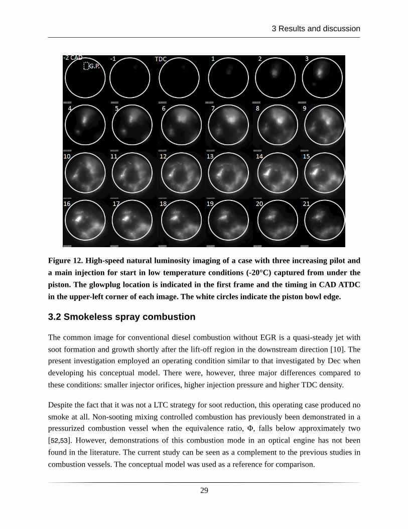
Figure 12. High-speed natural luminosity imaging of a case with three increasing pilot and a main injection for start in low temperature conditions (-20°C) captured from under the piston. The glowplug location is indicated in the first frame and the timing in CAD ATDC in the upper-left corner of each image. The white circles indicate the piston bowl edge.
3.2 Smokeless spray combustion
The common image for conventional diesel combustion without EGR is a quasi-steady jet with soot formation and growth shortly after the lift-off region in the downstream direction [10]. The present investigation employed an operating condition similar to that investigated by Dec when developing his conceptual model. There were, however, three major differences compared to these conditions: smaller injector orifices, higher injection pressure and higher TDC density.
Despite the fact that it was not a LTC strategy for soot reduction, this operating case produced no smoke at all. Non-sooting mixing controlled combustion has previously been demonstrated in a pressurized combustion vessel when the equivalence ratio, Φ, falls below approximately two[52,53]. However, demonstrations of this combustion mode in an optical engine has not been found in the literature. The current study can be seen as a complement to the previous studies in combustion vessels. The conceptual model was used as a reference for comparison.
3 Results and discussion
29
The results obtained with combined simultaneous laser diagnostics revealed a significant difference in the soot formation process. Laser induced incandescence at 1064 nm showed the absence of soot in the section of the jet between the lift-off region (16 mm from the nozzle) and the bowl wall (40 mm from the nozzle). However, high-speed line of sight natural-luminescence measurements showed the presence of soot close to the bowl wall along the bowl floor. The soot luminosity vanishes shortly after the CA50 timing. These results imply that the soot formation process in the present case is much slower than the in the conceptual model case and is therefore visible in the far downstream regions of the jet, i.e. in the recirculation zones.
The absence of soot in the section of the free part of the jet, i.e. before reaching the bowl wall, can be explained by lower local equivalence ratios in the center of the jet. Theoretical calculations using the air entrainment model by Naber and Siebers show that the mean equivalence ratio across the jet section at lift-off is below 1.5. A threshold value of two was identified as the sooting threshold for diesel jets [11].
The high air entrainment rate in the present study compared to Dec’s conceptual model can be explained by the parameters named earlier. Mainly, the smaller orifice diameter causes significant air entrainment increase. The higher ambient density is also affecting the air entrainment but to a lesser degree. Finally, the higher injection pressure is believed to reduce the residence time of a fuel element at a given location in the jet. A shorter residence time at a given soot formation rate will result in a lower overall soot production.
Fluorescence signal from 355 nm PLIF was not found upstream of the lift-off region when moving the laser sheet closer to the injector. The OH signal from OH-PLIF forms an envelope around the 355 PLIF signal and is found more upstream, i.e. at the lift-off region, see schematic in Figure 13.
Signal from 355 PLIF originates from the fluorescence of partially oxidized fuel (POF). This name gathers ketones, aldehydes (e.g. formaldehyde) and polyaromatic hydrocarbons (PAH). Formaldehyde is typically found in regions that have gone through low temperature reactions whereas PAH are found in fuel rich regions and are regarded as soot precursors. A spectral analysis of the signal would enable the differentiation between formaldehyde and PAH, although such measurements were not performed at the time of the experiments. However, given the relatively lean mixtures at lift-off (Φ below 1.5), the absence of soot in the jet section, and the low intensity of the 355 PLIF signal, it is likely that PAH is not a dominating source of fluorescence in the present case.
3 Results and discussion
30
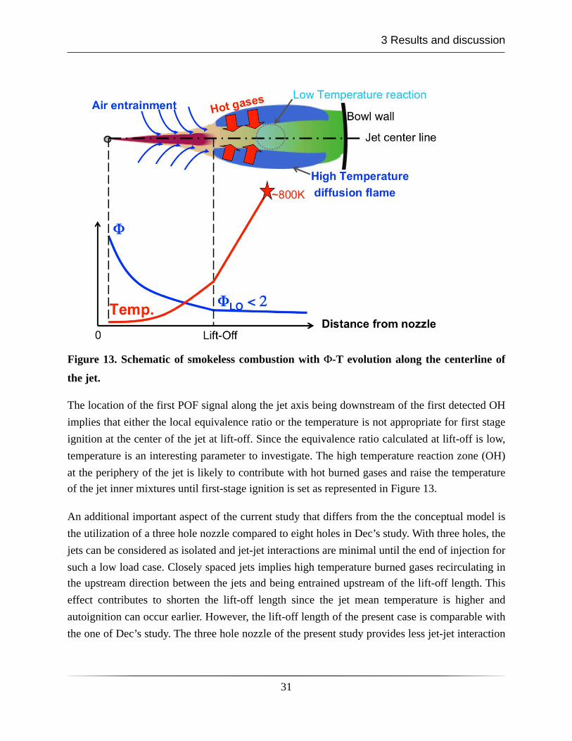
Figure 13. Schematic of smokeless combustion with Φ-T evolution along the centerline of
the jet.
The location of the first POF signal along the jet axis being downstream of the first detected OH implies that either the local equivalence ratio or the temperature is not appropriate for first stage ignition at the center of the jet at lift-off. Since the equivalence ratio calculated at lift-off is low, temperature is an interesting parameter to investigate. The high temperature reaction zone (OH) at the periphery of the jet is likely to contribute with hot burned gases and raise the temperature of the jet inner mixtures until first-stage ignition is set as represented in Figure 13.
An additional important aspect of the current study that differs from the the conceptual model is the utilization of a three hole nozzle compared to eight holes in Dec’s study. With three holes, the jets can be considered as isolated and jet-jet interactions are minimal until the end of injection for such a low load case. Closely spaced jets implies high temperature burned gases recirculating in the upstream direction between the jets and being entrained upstream of the lift-off length. This effect contributes to shorten the lift-off length since the jet mean temperature is higher and autoignition can occur earlier. However, the lift-off length of the present case is comparable with the one of Dec’s study. The three hole nozzle of the present study provides less jet-jet interaction
3 Results and discussion
31
and entrainment of hot gases but higher TDC density and injection pressure compensate for it and the lift-off stabilizes approximately at the same location.
3.3 UHC reduction by post-injection for an LTC case
Low temperature combustion is a concept aimed at reducing NOx and PM from diesel engines by dilution of the charge with large amounts of cooled EGR, as described in a previous section. However, drawbacks in terms of elevated UHC emissions are known for low load LTC conditions.
Previous studies have shown that over leaning of the jet after end of injection, due to enhanced air entrainment, results in mixtures too lean to ignite in the near-injector region. This behavior is especially seen at low loads when the ignition dwell, i.e. time between end of injection and start of combustion, is large.
The objective of this study was to investigate the potential of post-injections to locally increase the equivalence ratio and render the mixtures ignitable in order to reduce UHC emissions from low load LTC. Issues with over-mixing after the end of the post injection, creating the same UHC problem, were solved by adjusting the post-injection parameters as described later in this section.
Combined laser diagnostics were used for indirect measurements of mixing. Combustion intermediates were used as indicators of the local stoichiometry. Formaldehyde can be found in regions ranging from fuel lean to fuel rich but it persists late in the cycle only in fuel lean regions. Furthermore, OH concentrations are high in near-stoichiometric regions. Third, PAH is known as a soot precursor and is found in overall fuel rich regions. Using combined OH and 355nm PLIF, the different combustion intermediates can be imaged and give information about the local stoichiometry. Formaldehyde and PAH can be extracted from spectral analysis of the 355-PLIF fluorescence signal since formaldehyde has a particular spectrum with seven distinct peaks between 385 and 445 nm.
It was found that for a single injection, OH radicals are formed in the downstream regions close to the bowl wall and stagnate in this location late in the cycle as shown in Figure 15. Formaldehyde, i.e. lean regions, are found after EOI around the injector in the center of the bowl as seen in Figure 14. No sign of fuel rich regions were observed for this case.
A post-injection strategy able to reduce measured exhaust UHC emissions was found to be achievable, though very sensitive to the settings of the post-injection. A case with 20% decrease
3 Results and discussion
32
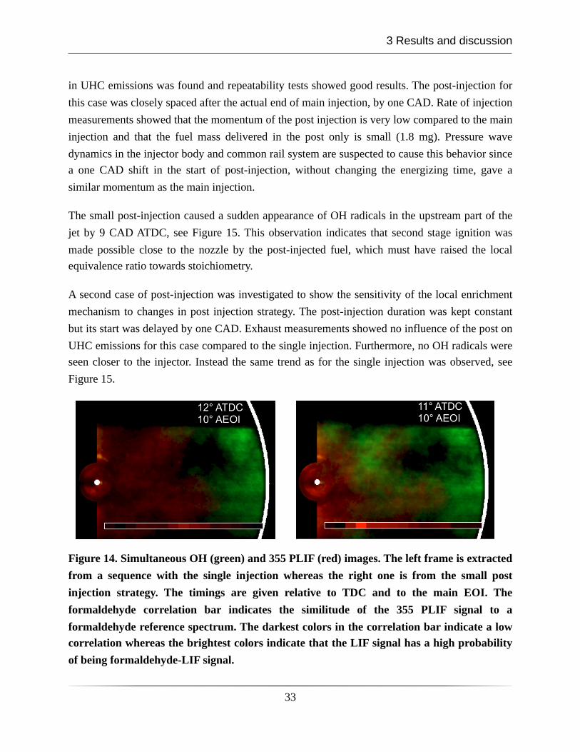
in UHC emissions was found and repeatability tests showed good results. The post-injection for this case was closely spaced after the actual end of main injection, by one CAD. Rate of injection measurements showed that the momentum of the post injection is very low compared to the main injection and that the fuel mass delivered in the post only is small (1.8 mg). Pressure wave dynamics in the injector body and common rail system are suspected to cause this behavior since a one CAD shift in the start of post-injection, without changing the energizing time, gave a similar momentum as the main injection.
The small post-injection caused a sudden appearance of OH radicals in the upstream part of the jet by 9 CAD ATDC, see Figure 15. This observation indicates that second stage ignition was made possible close to the nozzle by the post-injected fuel, which must have raised the local equivalence ratio towards stoichiometry.
A second case of post-injection was investigated to show the sensitivity of the local enrichment mechanism to changes in post injection strategy. The post-injection duration was kept constant but its start was delayed by one CAD. Exhaust measurements showed no influence of the post on UHC emissions for this case compared to the single injection. Furthermore, no OH radicals were seen closer to the injector. Instead the same trend as for the single injection was observed, see Figure 15.
Figure 14. Simultaneous OH (green) and 355 PLIF (red) images. The left frame is extracted from a sequence with the single injection whereas the right one is from the small post injection strategy. The timings are given relative to TDC and to the main EOI. The formaldehyde correlation bar indicates the similitude of the 355 PLIF signal to a formaldehyde reference spectrum. The darkest colors in the correlation bar indicate a low correlation whereas the brightest colors indicate that the LIF signal has a high probability of being formaldehyde-LIF signal.
3 Results and discussion
33
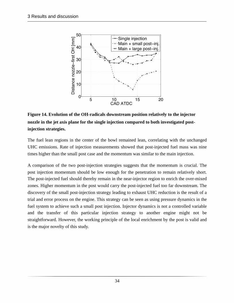
Figure 14. Evolution of the OH-radicals downstream position relatively to the injector
nozzle in the jet axis plane for the single injection compared to both investigated post-injection strategies.
The fuel lean regions in the center of the bowl remained lean, correlating with the unchanged UHC emissions. Rate of injection measurements showed that post-injected fuel mass was nine times higher than the small post case and the momentum was similar to the main injection.
A comparison of the two post-injection strategies suggests that the momentum is crucial. The post injection momentum should be low enough for the penetration to remain relatively short. The post-injected fuel should thereby remain in the near-injector region to enrich the over-mixed zones. Higher momentum in the post would carry the post-injected fuel too far downstream. The discovery of the small post-injection strategy leading to exhaust UHC reduction is the result of a trial and error process on the engine. This strategy can be seen as using pressure dynamics in the fuel system to achieve such a small post injection. Injector dynamics is not a controlled variable and the transfer of this particular injection strategy to another engine might not be straightforward. However, the working principle of the local enrichment by the post is valid and is the major novelty of this study.
3 Results and discussion
34
6 References1. Taylor, A.M.K.P, ”Science review of internal combustion engines”, Energy Policy 36,
2008, pp. 4657-46672. Thiel, C., Perujo, A., Mercier, A., ”Cost and CO2 aspects of future vehicle options in
Europe under new energy policy scenario”, Energy Policy 38, 2010, pp. 7142-71513. American physical society physics of sustainable energy at UC, Berkeley, March 1–2,
2008 opening talk by Steve Chu, director of Lawrence Berkeley National Laboratory; associated paper: (Chu, S., Chapter 1, Science of Photons to Fuels). In: Hafemeister, D., Levi, B., Levine, M., Schwartz, P. (Eds.), Physics of Sustainable Energy. American Institute of Physics Press, College Park, MD
4. Bossel, U., ”Does a Hydrogen Economy Make Sense”, Proceeding of the IEEE, vol. 94, No. 10, October 2006
5. European Commission, Joint Research Center, ”Well-to-Wheels analysis of future automotive fuels and powertrains in the European context”, http://ies.jrc.ec.europa.eu/uploads/media/WTW_010307.pdf , 8/11/2010
6. Bossel, U.,”The hydrogen ”Illusion”, COSSP Cogeneration & On-Site Power Production,” 2004
7. Diesel share in the European market from European Automobile Manufacturers Association, available at http://www.acea.be/images/uploads/files/20090317_All.jpg 08/11/2010
8. Cummins, L., ”Internal Fire”, Carnot Press, Oregon, 20009. Rate of heat release available at http://www.dieselnet.com/tech/diesel_comb.html
10/11/201010. Dec, J.E., ”A Conceptual Model of DI Diesel Combustion Based on Laser-Sheet
Imaging”, presented at SAE World Congress, 970873, 199711. Akihama, K., Takatori, Y., Inagaki, K., Sasaki, S. and Dean, A.M., ”Mechanism of the
Smokeless Rich Diesel Combustion by Reducing Temperature”, SAE paper 2001-01-0655, 2001
12. Pickett, L.M. and Siebers, D.L., ”Soot Formation in Diesel Fuel Jets Near the Lift-Off Length”, International Journal of Engine Research, 7(2), 2006
13. Idicheria, C.A. and Pickett, L.M., ”Soot Formation in Diesel Combustion under High-EGR Conditions”, SAE paper 2005-01-3834, 2005
14. Pickett, L.M. and Siebers, D.L., ”Non-Sooting, Low Flame-Temperature Mixing-Controlled DI Diesel Combustion”, SAE paper 2004-01-1399, 2004
15. Siebers, D.L., ”Scaling Liquid-Phase Fuel Penetration in Diesel Sprays Based on Mixing-Limited Vaporization”, presented at SAE World Congress, 1999-01-0528, 1999
16. Musculus, M.P.B., ”Multiple Simultaneous Optical Diagnostic Imaging of Early-Injection Low-Temperature Combustion in a Heavy-Duty Diesel Engine”, SAE paper 2006-01-0079, 2006
6 References
35
17. Musculus, M. P. B., Lachaux, T., Pickett, L. M., and Idicheria, C. A., "End-of-Injection Over-Mixing and Unburned Hydrocarbon Emissions in Low- Temperature-Combustion Diesel Engines," SAE Paper 2007-01-0907, SAE Transactions, 116, No. 3, pp. 515-541, 2007
18. Musculus, M.P.B., and Kattke, K., “Entrainment Waves in Diesel Jets”, SAE paper 2009-01-1355, 2009
19. Moon, S., Matsumoto, Y., and Nishida, K., “Entrainment, Evaporation and Mixing Characteristics of Diesel Sprays around End-of-Injection,” SAE paper 2009-01-0849, 2009
20. Naber, J.D. and Siebers, D.L., "Effects of Gas Density and Vaporization on Penetration and Dispersion of Diesel Sprays," SAE Paper 960034, SAE Transactions, 105, No. 3, pp. 82-111, 1996
21. European emission standards. Available at: http://www.dieselnet.com/standards 08/11/2010
22. Ken-ichiro Inoue , Hirohisa Takano , Rie Yanagisawa , Seishiro Hirano , Takahiro Kobayashi , Yuji Fujitani , Akinori Shimada , Toshikazu Yoshikawa, ” Effects of inhaled nanoparticles on acute lung injury induced by lipopolysaccharide in mice”, Toxicology 238 (2007) 99–110
23. Kamimoto, T. and Bae, M., “High Combustion Temperature for the Reduction of Particulate in Diesel Engines”, SAE paper 880423
24. Kook S., Bae C., Miles P.C., Choi D., and Pickett L.M., “The Influence of Charge Dilution and Injection Timing on Low-Temperature Diesel Combustion and Emissions”, SAE Paper No. 2005-01-3837
25. Soot oxidation zone in the Φ-T map available at http://www.dieselnet.com/tech/diesel_comb.html 15/11/2010
26. Heywood, J.B., Internal Combustion Engine Fundamentals, McGraw-Hill Book Co, New York, US, 1988
27. Pierpont, D. A., Montgomery, D. T. and Reitz, R. D., ”Reducing particulate and NOx using multiple injections and EGR in a D. I. diesel”. SAE paper 950217
28. Alriksson, M., ”An Investigation of Low Temperature Combustion Using high Levels of EGR”, Licentiate thesis, Chalmers University of Technology, 2007
29. Ekoto, I., Colban, W.F., Miles, P.C., Wook Park, S., Foster, D.E., Reitz, R.D., ”UHC Emissions Sources from a Light-Duty Diesel Engine Undergoing Dilution Controlled Low Temperature Combustion”, SAE paper 2009-01-1446, 2009
30. Kim, D., Ekoto, I., Colban, W.F. and Miles, P.C., ”In-Cylinder CO and UHC Imaging in a Light-Duty Diesel Engine During PPCI Low-Temperature Combustion”, SAE paper 2008-01-1602, 2008
31. Fasolo, B., Doisy, A.M., Dupont, A., Lavoisier, F., “Combustion System Optimization of a New 2 Liter Diesel Engine for EURO IV”, SAE paper 2005-01-0652
32. Stanton, D.W., Lippert, A.M., Reitz, R.D., Rutland, C.J., “Influence of Spray-Wall Interaction and Fuel Films on Cold Starting in Direst Injection Diesel Engines”, SAE paper 982584
6 References
36
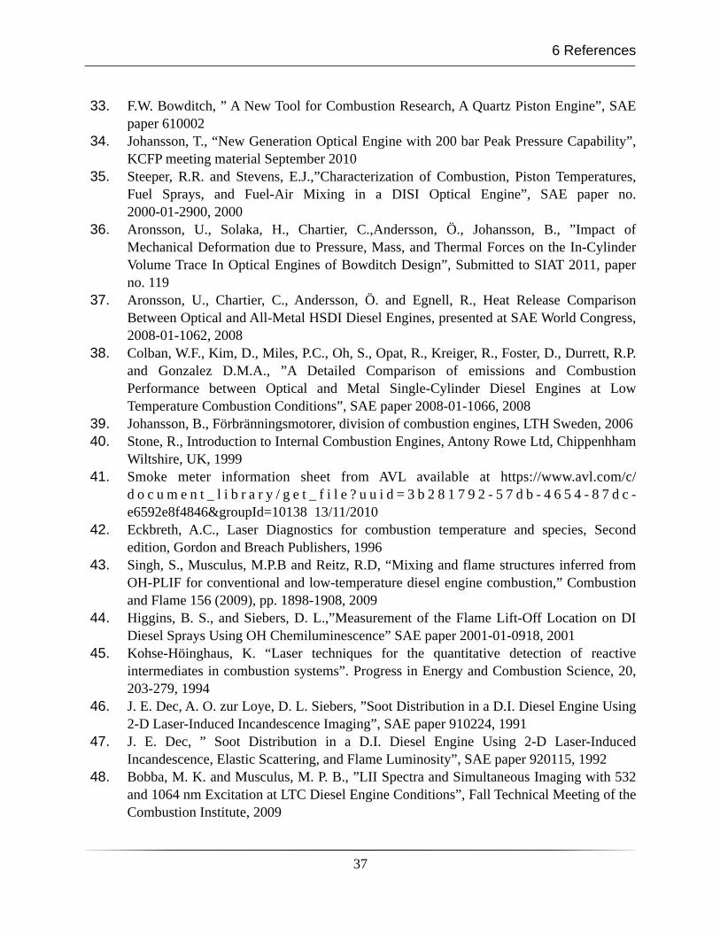
33. F.W. Bowditch, ” A New Tool for Combustion Research, A Quartz Piston Engine”, SAE paper 610002
34. Johansson, T., “New Generation Optical Engine with 200 bar Peak Pressure Capability”, KCFP meeting material September 2010
35. Steeper, R.R. and Stevens, E.J.,”Characterization of Combustion, Piston Temperatures, Fuel Sprays, and Fuel-Air Mixing in a DISI Optical Engine”, SAE paper no. 2000-01-2900, 2000
36. Aronsson, U., Solaka, H., Chartier, C.,Andersson, Ö., Johansson, B., ”Impact of Mechanical Deformation due to Pressure, Mass, and Thermal Forces on the In-Cylinder Volume Trace In Optical Engines of Bowditch Design”, Submitted to SIAT 2011, paper no. 119
37. Aronsson, U., Chartier, C., Andersson, Ö. and Egnell, R., Heat Release Comparison Between Optical and All-Metal HSDI Diesel Engines, presented at SAE World Congress, 2008-01-1062, 2008
38. Colban, W.F., Kim, D., Miles, P.C., Oh, S., Opat, R., Kreiger, R., Foster, D., Durrett, R.P. and Gonzalez D.M.A., ”A Detailed Comparison of emissions and Combustion Performance between Optical and Metal Single-Cylinder Diesel Engines at Low Temperature Combustion Conditions”, SAE paper 2008-01-1066, 2008
39. Johansson, B., Förbränningsmotorer, division of combustion engines, LTH Sweden, 200640. Stone, R., Introduction to Internal Combustion Engines, Antony Rowe Ltd, Chippenhham
Wiltshire, UK, 199941. Smoke meter information sheet from AVL available at https://www.avl.com/c/
d o c u m e n t _ l i b r a r y / g e t _ f i l e ? u u i d = 3 b 2 8 1 7 9 2 - 5 7 d b - 4 6 5 4 - 8 7 d c -e6592e8f4846&groupId=10138 13/11/2010
42. Eckbreth, A.C., Laser Diagnostics for combustion temperature and species, Second edition, Gordon and Breach Publishers, 1996
43. Singh, S., Musculus, M.P.B and Reitz, R.D, “Mixing and flame structures inferred from OH-PLIF for conventional and low-temperature diesel engine combustion,” Combustion and Flame 156 (2009), pp. 1898-1908, 2009
44. Higgins, B. S., and Siebers, D. L.,”Measurement of the Flame Lift-Off Location on DI Diesel Sprays Using OH Chemiluminescence” SAE paper 2001-01-0918, 2001
45. Kohse-Höinghaus, K. “Laser techniques for the quantitative detection of reactive intermediates in combustion systems”. Progress in Energy and Combustion Science, 20, 203-279, 1994
46. J. E. Dec, A. O. zur Loye, D. L. Siebers, ”Soot Distribution in a D.I. Diesel Engine Using 2-D Laser-Induced Incandescence Imaging”, SAE paper 910224, 1991
47. J. E. Dec, ” Soot Distribution in a D.I. Diesel Engine Using 2-D Laser-Induced Incandescence, Elastic Scattering, and Flame Luminosity”, SAE paper 920115, 1992
48. Bobba, M. K. and Musculus, M. P. B., ”LII Spectra and Simultaneous Imaging with 532 and 1064 nm Excitation at LTC Diesel Engine Conditions”, Fall Technical Meeting of the Combustion Institute, 2009
6 References
37
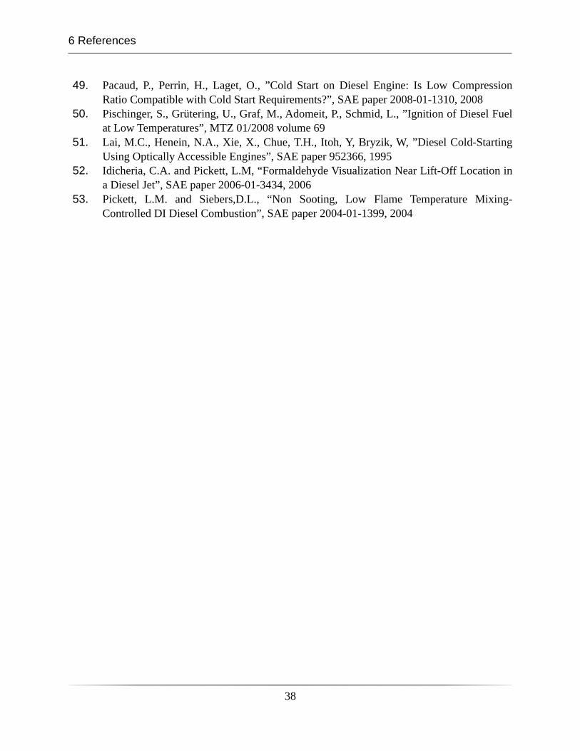
49. Pacaud, P., Perrin, H., Laget, O., ”Cold Start on Diesel Engine: Is Low Compression Ratio Compatible with Cold Start Requirements?”, SAE paper 2008-01-1310, 2008
50. Pischinger, S., Grütering, U., Graf, M., Adomeit, P., Schmid, L., ”Ignition of Diesel Fuel at Low Temperatures”, MTZ 01/2008 volume 69
51. Lai, M.C., Henein, N.A., Xie, X., Chue, T.H., Itoh, Y, Bryzik, W, ”Diesel Cold-Starting Using Optically Accessible Engines”, SAE paper 952366, 1995
52. Idicheria, C.A. and Pickett, L.M, “Formaldehyde Visualization Near Lift-Off Location in a Diesel Jet”, SAE paper 2006-01-3434, 2006
53. Pickett, L.M. and Siebers,D.L., “Non Sooting, Low Flame Temperature Mixing-Controlled DI Diesel Combustion”, SAE paper 2004-01-1399, 2004
6 References
38
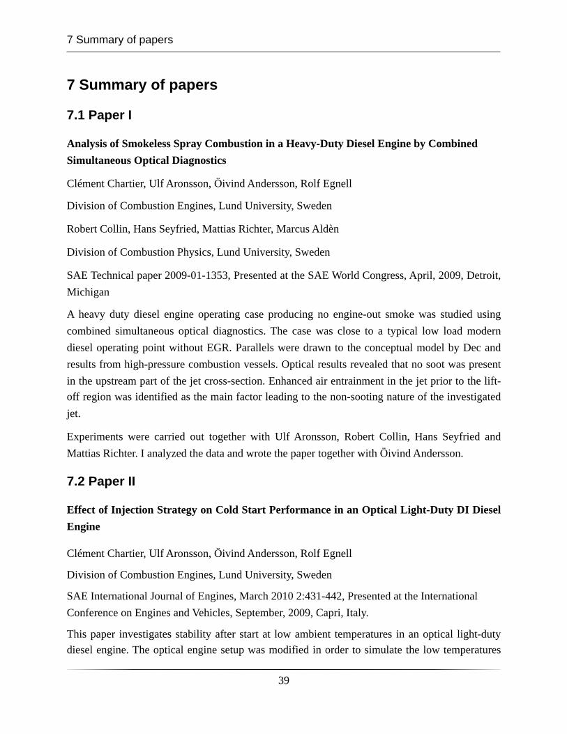
7 Summary of papers
7.1 Paper I
Analysis of Smokeless Spray Combustion in a Heavy-Duty Diesel Engine by Combined Simultaneous Optical Diagnostics
Clément Chartier, Ulf Aronsson, Öivind Andersson, Rolf Egnell
Division of Combustion Engines, Lund University, Sweden
Robert Collin, Hans Seyfried, Mattias Richter, Marcus Aldèn
Division of Combustion Physics, Lund University, Sweden
SAE Technical paper 2009-01-1353, Presented at the SAE World Congress, April, 2009, Detroit, Michigan
A heavy duty diesel engine operating case producing no engine-out smoke was studied using combined simultaneous optical diagnostics. The case was close to a typical low load modern diesel operating point without EGR. Parallels were drawn to the conceptual model by Dec and results from high-pressure combustion vessels. Optical results revealed that no soot was present in the upstream part of the jet cross-section. Enhanced air entrainment in the jet prior to the lift-off region was identified as the main factor leading to the non-sooting nature of the investigated jet.
Experiments were carried out together with Ulf Aronsson, Robert Collin, Hans Seyfried and Mattias Richter. I analyzed the data and wrote the paper together with Öivind Andersson.
7.2 Paper II
Effect of Injection Strategy on Cold Start Performance in an Optical Light-Duty DI Diesel Engine
Clément Chartier, Ulf Aronsson, Öivind Andersson, Rolf Egnell
Division of Combustion Engines, Lund University, Sweden
SAE International Journal of Engines, March 2010 2:431-442, Presented at the International Conference on Engines and Vehicles, September, 2009, Capri, Italy.
This paper investigates stability after start at low ambient temperatures in an optical light-duty diesel engine. The optical engine setup was modified in order to simulate the low temperatures
7 Summary of papers
39
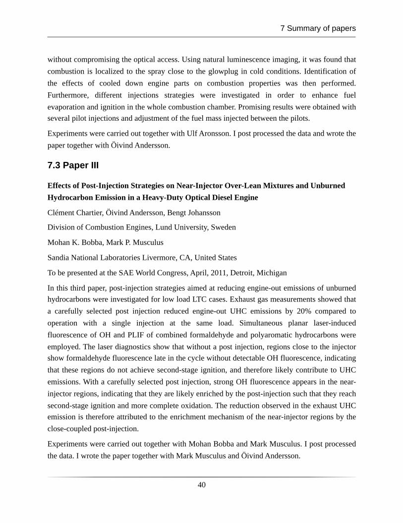
without compromising the optical access. Using natural luminescence imaging, it was found that combustion is localized to the spray close to the glowplug in cold conditions. Identification of the effects of cooled down engine parts on combustion properties was then performed. Furthermore, different injections strategies were investigated in order to enhance fuel evaporation and ignition in the whole combustion chamber. Promising results were obtained with several pilot injections and adjustment of the fuel mass injected between the pilots.
Experiments were carried out together with Ulf Aronsson. I post processed the data and wrote the paper together with Öivind Andersson.
7.3 Paper III
Effects of Post-Injection Strategies on Near-Injector Over-Lean Mixtures and Unburned Hydrocarbon Emission in a Heavy-Duty Optical Diesel Engine
Clément Chartier, Öivind Andersson, Bengt Johansson
Division of Combustion Engines, Lund University, Sweden
Mohan K. Bobba, Mark P. Musculus
Sandia National Laboratories Livermore, CA, United States
To be presented at the SAE World Congress, April, 2011, Detroit, Michigan
In this third paper, post-injection strategies aimed at reducing engine-out emissions of unburned hydrocarbons were investigated for low load LTC cases. Exhaust gas measurements showed that a carefully selected post injection reduced engine-out UHC emissions by 20% compared to operation with a single injection at the same load. Simultaneous planar laser-induced fluorescence of OH and PLIF of combined formaldehyde and polyaromatic hydrocarbons were employed. The laser diagnostics show that without a post injection, regions close to the injector show formaldehyde fluorescence late in the cycle without detectable OH fluorescence, indicating that these regions do not achieve second-stage ignition, and therefore likely contribute to UHC emissions. With a carefully selected post injection, strong OH fluorescence appears in the near-injector regions, indicating that they are likely enriched by the post-injection such that they reach second-stage ignition and more complete oxidation. The reduction observed in the exhaust UHC emission is therefore attributed to the enrichment mechanism of the near-injector regions by the close-coupled post-injection.
Experiments were carried out together with Mohan Bobba and Mark Musculus. I post processed the data. I wrote the paper together with Mark Musculus and Öivind Andersson.
7 Summary of papers
40