Embed Size (px)
Citation preview

Control of spray evaporative cooling in automotive IC engines
Article (Accepted Version)
http://sro.sussex.ac.uk
Jafari, S, Dunne, J, Langari, M, Yang, Z, Pirault, J, Long, C and Thalackottore Jose, J (2018) Control of spray evaporative cooling in automotive IC engines. Journal of Thermal Science and Engineering Applications, 10 (4). pp. 1-11. ISSN 1948-5085
This version is available from Sussex Research Online: http://sro.sussex.ac.uk/id/eprint/73266/
This document is made available in accordance with publisher policies and may differ from the published version or from the version of record. If you wish to cite this item you are advised to consult the publisher’s version. Please see the URL above for details on accessing the published version.
Copyright and reuse: Sussex Research Online is a digital repository of the research output of the University.
Copyright and all moral rights to the version of the paper presented here belong to the individual author(s) and/or other copyright owners. To the extent reasonable and practicable, the material made available in SRO has been checked for eligibility before being made available.
Copies of full text items generally can be reproduced, displayed or performed and given to third parties in any format or medium for personal research or study, educational, or not-for-profit purposes without prior permission or charge, provided that the authors, title and full bibliographic details are credited, a hyperlink and/or URL is given for the original metadata page and the content is not changed in any way.

American Society of
Mechanical Engineers
ASME Accepted Manuscript Repository
Institutional Repository Cover Sheet
First Last
ASME Paper Title: CONTROL OF SPRAY EVAPORATIVE COOLING IN AUTOMOTIVE IC ENGINES
Authors: S. Jafari, J. F. Dunne, M. Langari, Z. Yang J-P Pirault, C. A. Long, and J. Thalackottore Jose
ASME Journal Title: Journal of Thermal Science and Engineering Applications
Volume/Issue _________10/4___________________ Date of Publication (VOR* Online) 7th May 2018
ASME Digital Collection URL: https://doi.org/10.1115/1.4039701
DOI: 10.1115/1.4039701
*VOR (version of record)

TSEA-17-1087 DUNNE 1 ©ASME
CONTROL OF SPRAY EVAPORATIVE COOLING IN AUTOMOTIVE IC ENGINES
by
S. Jafari, J. F. Dunne*, M. Langari, Z. Yang$
J-P Pirault, C. A. Long, and J. Thalackottore Jose
Department of Engineering and Design School of Engineering and Informatics
University of Sussex, Falmer, Brighton, BN1 9QT, UK.
$Department of Engineering, College of Engineering and Technology, University of Derby, Derby DE22 3AW, UK.
* Corresponding author: E-mail: [email protected]

TSEA-17-1087 DUNNE 2
Abstract
A novel approach is proposed for precise control of two-phase spray evaporative cooling for thermal management of road vehicle internal combustion engines. A reduced-order plant model is first constructed by combining published spray evaporative cooling correlations with approximate governing heat transfer equations appropriate for IC engine thermal management. Control requirements are specified to allow several objectives to be met simultaneously under different load conditions. A control system is proposed and modelled in abstract form to achieve spray evaporative cooling of a gasoline engine, with simplifying assumptions made about the characteristics of the coolant pump, spray nozzle, and condenser. The system effectiveness is tested by simulation to establish its ability to meet key requirements, particularly concerned with precision control during transients resulting from rapid engine load variation. The results confirm the robustness of the proposed control strategy in accurately tracking a specified temperature profile at various constant load conditions, and also in the presence of realistic transient load variation.
Keywords: engine cooling, road vehicles, evaporative sprays, precision control, robustness.
17 main-section pages (double spaced) 58 references Figures 1 – 13 No appendices

TSEA-17-1087 DUNNE 3
Nomenclature
A area
Bo boiling number (defined in Equation 3)
C specific heat capacity
D diameter
d32 Sauter mean diameter
hfg specific enthalpy of vaporisation
H nozzle exit to wall distance
Ja Jakob number (defined in Equation 5)
k thermal conductivity
K three-way mixing valve constant
m mass
p pressure
q heat flux
Q heat flow
t time
T temperature
U velocity
w plate thickness
We Weber number (defined in Equation 4)
, and constants in Equation 2
∆p pressure difference
∆T temperature difference
dynamic viscosity
density
surface tension
Subscripts
c pertaining to the coolant
L, v pertaining to the liquid and vapour phases, respectively
in, out pertaining to inlet and outlet conditions, respectively
o pertaining to the nozzle exit
w,c, w,g pertaining to wall coolant side and gas side, respectively

TSEA-17-1087 DUNNE 4
1. INTRODUCTION
The development of new cooling strategies across a range of different application areas has
resulted in a high degree of functionality for both component hardware and cooling systems.
This includes applications within the automotive sector, aerospace, electronics, and the
nuclear industry. In the electronics industry for example, the ever-demanding requirements
of the ‘lab-on-a-chip’, has made thermal management a major challenge. And of particular
relevance in the automotive sector, thermal management of ‘highly-boosted’ internal
combustion engines is placing a serious limit on the ability to improve engine efficiency by
‘downsizing’. Temperature control of complex systems in these sectors plays a vital role in
achieving consistent system performance. This may mean either tracking a prescribed
temperature profile or maintaining values within very carefully specified thermal limits. And
although further advances in cooling technology may overcome the current limitations of
existing cooling methods, precise thermal management may not be possible with existing
control strategies. The focus of this paper is to find an appropriate control strategy to realise
the full benefits of spray evaporative cooling for combustion engines that will mainly be used
for automotive vehicle propulsion in the light-duty sector.
The design of any cooling system requires careful consideration of several interrelated
factors: e.g. the maximum permissible heat flux and temperature, thermally-induced
stresses, tolerances, reliability, parasitic energy consumption (of the cooling system), and
the operating environment. As shown in figure 1 [1], spray evaporative cooling offers great
potential for heat removal because the heat transfer coefficient is an order of magnitude
greater than in nucleate boiling, and two orders of magnitude greater than single phase
forced-convection with water. This enhancement in heat transfer over more-conventional
cooling systems is a result of the complete evaporation of small (sub-millimetre diameter)
droplets which impinge onto the heated surface.

TSEA-17-1087 DUNNE 5
The first experimental evidence of spray cooling on solid surfaces was reported in 1966
[2][3] - the result of carefully examining the spray cooling mechanism and the associated
boiling curves generated in [4]. The first empirical spray cooling correlations were obtained
4 years later [5-7]. But it took another 20 years to understand the principal concepts involved
and to derive correlations for single (liquid) phase spray cooling. The milestones for this
(single-phase) period are summarised in Table 1.
Table 1 – Milestones in spray cooling research (1966-1985)
Main achievement Year
1 Surface temperature and coolant temperature play are important in spray cooling effectiveness [2].
1966
2 Specific water impact density implies a specific boiling curve [3]. 1966
3 There is a strong relationship between the heat transfer coefficient and the spray mass flux [5-7].
1970
4 Different regions needs different correlations to analyse [8-9]. 1972 1974
5 Strong dependency of the heat transfer coefficient on the coolant temperature [10-11].
1979 1980
6 The heat transfer effectiveness is a function of the inverse of the square root of droplet diameter [12].
1982
7 The spray cooling behaviour on a flat surface is hypothesized [13]. 1984
In the late 1980s, detailed studies on two-phase spray cooling were undertaken to
understand and establish the effects on heat transfer of droplet size and velocity, mass flow
rate, injector nozzle geometry, and the amount of sub-cooling [13-17]. It was in this period
that a maximum heat flux of around 12 MW/m2 was shown to be achievable with
‘superheating’ of only 20C (where here the term ‘superheat’ refers to the difference between
the temperature of the target surface and the coolant saturation temperature). This
confirmed the dramatic improvement in heat transfer possible using spray evaporative

TSEA-17-1087 DUNNE 6
cooling [19-21]. But it also confirmed that it is possible to avoid the undesirable transition
boiling phenomenon that occurs for high excess temperature differences in both the pool
and flow boiling regimes.
The first practical application of spray evaporative cooling was reported in 1994 in an
application to a computer processor [22], where miniature atomisers were used to spray a
dielectric coolant. Other notable achievements in the development of spray cooling
technology were the experimental studies on generating single-phase spray correlations
[23-24]; the work on two-phase spray correlations [25-28]; and the spray parameter
correlations (i.e. the ‘Sauter Mean Diameter’, and the ‘critical heat flux’) [29-30]. Finally, the
notable achievements in studying the sensitive effect that spray parameters have on the
heat transfer characteristics are reported in [31-35].
In the past decade, research has focused mainly on the challenges of implementing spray
cooling in practical applications. The main challenge is that of control, in particular how the
system parameters (coolant temperature and nozzle pressure difference) can be regulated
to effectively control surface temperatures. Rybicki and Mudawar [36] undertook
experimental studies to assess the effects of spray orientation on cooling performance,
developing general correlations for single-phase heat transfer, nucleate boiling, and the
critical heat flux. They showed that regulation of spray mass flow rate, and Sauter mean
diameter, are the key hydrodynamic parameters that influence spray cooling performance.
The results of the numerical modelling of multiphase flow spray cooling by Selvan et al. [37],
showed that regulating spray parameters (in order to maintain a thin film over the heated
surface, and its interaction with impinging liquid droplets) is very important for heat removal
at high heat flux values [37].
Three comprehensive, theoretical and experimental studies on spray evaporative cooling
(and its application) were published in 2008 and 2009 by Mudawar and Visaria [38-40]. They
showed that the onset of nucleate boiling, critical heat flux, the evaporation efficiency, and

TSEA-17-1087 DUNNE 7
the magnitude of heat flux could all be changed by varying the amount of sub-cooling and
mass flow. In 2009, Mudawar et al. [41] explored the viability and implementation of spray
cooling for hybrid vehicle electronics, demonstrating that spray cooling is feasible for thermal
management of hybrid vehicle electronics. However, despite proposing a viable system
design, the control problem was not discussed. In 2010, Tilton and Tilton [42] patented a
design for a thermal management system using spray evaporative cooling of
microprocessors and other electronic devices. They did not propose any particular type of
control strategy but suggested a passive solution involving sloped-surfaces and drain-
channels to direct coolant across the surface in order to manage the surface temperature.
In 2016 Cheng et al. [43] published a comprehensive review of both spray and flash
evaporation cooling, in which the challenges for future development and applications were
discussed. Different applications of spray cooling were examined for supercomputers [44],
spacecraft [45], automotive engineering [41], and reactor pressure vessels [46]. The
challenges identified in these publications were: i) development of a suitable control
strategy, ii) the adoption of good spray tactics to avoid droplet rebound from the heated
surface, and iii) the improvement of droplet distribution. ‘Good tactics’ ultimately means: i)
the proper match between the frequency and duration of consecutive injection cycles
needed to control heat transfer, ii) the homogeneous dispersion of droplets, and iii) control
of the liquid deposited to avoid excessive secondary atomization or pre-impingement-
evaporation.
In this paper, a control strategy and control system are proposed for a spray evaporative
cooling of highly-boosted light-duty automotive engines. This control strategy and system,
potentially offer a highly-effective cooling method accruing benefits of reduced fuel
consumption and carbon emissions, reduced engine mass, better knock control, and more
uniform cylinder head temperatures. The proposed control strategy has been developed to
meet two main requirements: performance and robustness.

TSEA-17-1087 DUNNE 8
The paper is structured as follows: in Section 2 a plant model is constructed to describe
the physics associated with spray evaporative cooling of an engine. This combines a
lumped-parameter conductive and convective heat transfer modelling approach with
published spray correlations. Section 3 describes the development of the control strategy
which is then implemented in the form of a simulation model. Section 4 gives the results of
three different types of simulation test involving a i) compatibility test, ii) a robustness test,
and iii) steady and transient engine tests at part- and full-load. These simulated tests are
designed to demonstrate the effectiveness of the proposed methodology in satisfying
system requirements. The objective of the paper is to confirm the potential of the proposed
cooling control methodology for spray evaporative cooling of highly-boosted automotive
engines.
2. A MODEL FOR SPRAY EVAPORATIVE COOLING
This section describes the construction of a reduced-order mathematical model to represent
the physical ‘plant’ associated with spray evaporative cooling of an internal combustion
engine. This plant model will ultimately be controlled to demonstrate its effectiveness in
thermal management. First, the empirical equations needed to model spray evaporative
heat transfer physics are adapted, and the key dimensionless parameters established. A
reduced-order model is then obtained in the form of a lumped-parameter heat-balance
model which is followed by an iterative parameter selection procedure to enable a specific
plant model to be constructed. This is achieved by selecting a particular nozzle type, and
obtaining associated nozzle parameters. An overall (specific) plant model is thus obtained
which has sufficient accuracy to allow a controlled version of the system model to be
simulated. The controller, and the simulation model, will be developed in Section 3,

TSEA-17-1087 DUNNE 9
2.1 Empirical correlations and nozzle selection for spray evaporative cooling
To model temperature control of conventional IC engine cooling systems, several
experimentally-validated, lumped-parameter models have been cited in the literature, such
as Wagner et al. [47-49] , Eberth et al. [50], Henry et al. [51], Setlur et al. [52], and Page et
al. [53]. The governing equation used in all of these studies stems from a simple heat
balance which assumes that the engine can be represented as a single mass m, with
sections of spatially-uniform (but time-varying) temperature T:
𝑚 𝐶�̇� = �̇�𝑖𝑛 − �̇�𝑜𝑢𝑡 (1)
where �̇�𝑖𝑛 is the rate of heat-release from the combustion process to the engine block (a
function of engine load), �̇�𝑜𝑢𝑡 is the heat dissipation rate to the cooling system, C is the
engine block specific heat capacity. The heat input: �̇�𝑖𝑛, and the temperature T, are set by
design, since the engine wall temperatures depend on the duty cycle. A cooling control
system must therefore not only be able to deal with a prescribed variation in heat load but
must also be able to track variations in engine temperature (specified as set-points).
For spray evaporative cooling, with a nozzle-to-wall distance H, and a surface-to-coolant
temperature difference ∆T, �̇�𝑜𝑢𝑡 can be calculated using established correlations [27-28,
54-55]. To be specific: for a fluid of density L , dynamic viscosity , surface tension , and
specific enthalpy of vaporisation hfg, the spray cooling heat flux outout qQ can be obtained
using a non-dimensional correlation [27] expressing the Boiling Number Bo as a function of
the Weber Number We, and the Jakob Number Ja. This takes the form:
𝐵𝑜 = 𝛼 (𝑊𝑒)𝛽(𝐽𝑎)𝛾 (2)
where the Boiling Number is defined as:
𝐵𝑜 =�̇�𝑜𝑢𝑡𝐻
𝜇𝐿 ℎ𝑓𝑔 (3)
the Weber Number defined as:

TSEA-17-1087 DUNNE 10
𝑊𝑒 =𝜌𝐿𝑢0
2𝑑32
𝜎 (4)
and the Jakob Number defined as:
𝐽𝑎 =𝐶𝐿 𝛥𝑇
ℎ𝑓𝑔 (5)
The constant parameters in equation (2) for water are: = 15.6, = 0.59 and = 1.68. Also,
the exit velocity Uo operating with a pressure difference ∆p, and a discharge coefficient of
unity, is given by the usual expression:
𝑈𝑜 = (2 ∆𝑝
𝜌𝐿)1/2
(6)
The Sauter Mean Diameter (SMD) of the spray droplets (needed in equation (4)) for a nozzle
of exit diameter do, is obtained from the correlation [26, 29]:
𝑑32
𝑑0= 3.07 [
𝜌𝑣1/2
∆𝑃 𝑑03/2
𝜎1/2𝜇𝐿]−0.259
(7)
where 𝜌𝑣 is the vapour density.
2.2 Explicit plant model design procedure
To construct an explicit plant model, it is necessary to consider a specific set of conditions
because the model must be obtained iteratively. A schematic diagram of the reduced order
model is shown in figure 2. The cooled surface is represented by area A, of thickness w,
thermal conductivity k, and with respective wall temperatures on the coolant and gas side
as Tw,c and Tw,g. By substituting equations (2) - (7) into equation (1) setting outout qQ , the
model for the coolant-side wall temperature is given as:
𝑚𝐶�̇�𝑤,𝑐 = �̇�𝑖𝑛(𝑡) − 30.236𝐴𝜇𝐿ℎ𝑓𝑔
𝐻[𝐶𝐿𝛥𝑇
ℎ𝑓𝑔]1.68
[ 𝜌𝐿 𝑢02 𝑑0[
𝜌𝑣1/2
∆𝑃 𝑑03/2
𝜎1/2𝜇𝐿]
−0.259
𝜎
] 0.59
(8)
Considering a heat balance condition from the gas-side to the coolant-side, the heat transfer
rate can be expressed either in terms of conductive or convective heat transfer. By using a
lumped-mass approximation of conductive heat transfer (from the gas-side to the coolant

TSEA-17-1087 DUNNE 11
wall), and a convective heat transfer model (from the coolant-wall to the coolant) two
independent expressions can be constructed allowing elimination of the heat transfer
coefficient associated with coolant-wall-to-coolant heat transfer. This results in an
expression for the gas-side wall temperature as follows:
𝑚𝐶�̇�𝑤,𝑔 = �̇�𝑖𝑛(𝑡) − 𝐴 [𝑇𝑤,𝑔−𝑇𝑐
𝑤
𝑘 +𝐴
𝑇𝑤,𝑐−𝑇𝑐
�̇�𝑜𝑢𝑡(𝑡)
] (9)
Since the objective is to use heat transfer simulations to assess a proposed engine cooling
control system, the design space must be constrained within the boundaries set by the
applicability of the correlations used, and also within the limitations of the specified
hardware. To meet these design requirements various combinations of control system
configuration and nozzle option have been examined (but only the outcome is discussed
here). This best spray nozzle selection outcome culminates in a step-by-step iterative
procedure as follows:
Step-by-step spray nozzle selection procedure
Step-1: Set the chamber pressure 𝑃𝑐ℎ𝑎𝑚𝑏𝑒𝑟 and coolant temperature, Tc.
Step-2: Obtain tabulated values of coolant thermodynamic properties (liquid phase density ,
surface tension , liquid phase viscosity , specific and latent heats, C and hfg). Step-3: Select values of wall temperature, Tw,c, nozzle pump pressure Pnozzle, and nozzle-to-wall
distance, H and diameter d0. Obtain the heat flux from the following relationships: ∆𝑃 =𝑃𝑁𝑜𝑧𝑧𝑙𝑒 − 𝑃𝑐ℎ𝑎𝑚𝑏𝑒𝑟 and ∆𝑇 = 𝑇𝑤,𝑐 − 𝑇𝑐. Step-4: Obtain SMD, d32, from equation (7). Step-5: Obtain droplet velocity from equation (6). Step-6: Calculate Weber number from equation (4). Step-7: Calculate Jacob number from equation (5). Step-8: Calculate the boiling number from equation (3). Step-9: Obtain heat flux q, from Bo. If this value is unacceptable, go back to Step 3 and iterate.

TSEA-17-1087 DUNNE 12
The acceptable designed value for q is set to 1.6 MW/m2, which is considered to be the
largest value of local heat flux in a state-of-the-art boosted gasoline engine cylinder head at
full-load. The optimum spray-to-the-wall distance (i.e. parameter H in figure 2) is calculated
for the condition where the spray just spans the heated area to achieve the largest heat flux
as confirmed in [30]. As an example, the heated surface, as shown in figure 2, is modelled
as a circular block with diameter D = 30 mm, thickness w = 10 mm, and thermal conductivity
k = 205 W/(mK).
Following through this step-by-step spray nozzle selection procedure, the parameters
associated with the selected nozzle (i.e.: a Bete JP8 [56]), are shown in Table 2. The
calculated coolant mass flow rate of 0.77 gm/s corresponds to a mass flow rate of 81.41
gm/s for spray cooling of a 100 kW engine (which represents just 3.5% of the required 2280
gm/s coolant flow needed for a conventional cooling system). And although this is achieved
at the expense of a much higher coolant pump discharge pressure (i.e. 11.5 bar instead of
the 1.0 bar gauge pressure in a conventional system), spray evaporative cooling of an IC
engine still offers a 60% reduction in the cooling power consumption. This is expected to
bring significant benefits in improved fuel economy and reduced CO2 emissions. However,
these benefits can only be realised with a precise control and management strategy. The
development of an appropriate control and management strategy is therefore discussed in
Section 3.
Table 2. Spray nozzle specification
Spray cone angle
Nozzle injector
diameter (mm)
Droplet SMD, d32 (µm)
Mean impact velocity (m/s)
Nozzle to
Surface distance
(mm)
ΔP (bar)
Coolant Temp
(C)
Wall Temp
(C)
Weber number
We
Jacob number
Ja
Boiling number
Bo
Mass flow (g/s)
90 0.15 33 47 15 11.5 90 140 2338 0.093 28.28 1.46

TSEA-17-1087 DUNNE 13
3. CONTROL SYSTEM DESIGN FOR SPRAY EVAPORATIVE COOLING OF ENGINES
The ultimate objective of an engine cooling control system is to maintain the gas-side wall
temperature 𝑇𝑤,𝑔(𝑡) within pre-defined limits under all operating conditions. An engine
cooling controller should therefore be able to precisely track engine temperature set-points
while compensating for both cyclic and progressive variations in the combustion heat
release which is effectively a heat input �̇�𝑖𝑛(𝑡) to the cooling jacket of the engine block.
Equations 8 and 9 show that the control parameters in a spray evaporative cooling system
are: the coolant temperature 𝑇𝐿, and the pressure difference ∆p across the spray nozzle.. It
is practically impossible to measure gas-side metal temperatures of a running engine but
the coolant-side wall temperature, and the vapour chamber pressure, can be easily
measured (for example, respectively using a thermocouple and a pressure sensor).
Assuming the system parameters, such as the engine jacket mass m, the specific heat
capacity 𝐶 of the jacket metal, and relevant dimensions, are known constants, the control
problem can be considered in terms of regulating the coolant-side metal temperatures rather
than the gas-side metal temperatures. To be specific, the requirement is to precisely track
a desired coolant-side wall temperature with the aim of keeping the gas-side wall
temperature within a reasonable pre-defined range for all operating conditions. The
operating conditions for the highest heat flux regions of the cylinder head are intended to
replicate engine behaviour under both part- and full-load conditions corresponding to
respective heat flux levels of �̇�𝑖𝑛 = 0.2 MW/m2 and �̇�𝑖𝑛 = 1.5 MW/m2. A control structure is
proposed in figure 3, which will be shown by simulation to precisely achieve the desired
temperature tracking for these load conditions. This contains two control loops and a
regulating mechanism as now explained in the following sub sections:

TSEA-17-1087 DUNNE 14
The spray coolant pump pressure control loop
First, a coolant pump pressure PID control loop is designed (i.e. the dashed line shown in
figure 3). The purpose is to regulate the coolant supply pump pressure upstream of the spray
nozzle to enable the pressure difference ∆𝑝 in equation (8) to be set. The difference between
the coolant-side wall temperature, and the desired wall temperature, is used as the error
signal in the controller to regulate the nozzle pressure.
The spray coolant temperature control loop
The coolant temperature control loop is shown as a dotted line in figure 3. This loop
regulates the coolant temperature using the chamber pressure, and a pre-defined degree
of ‘sub-cooling’ (where the term ‘sub-cooling’ here refers to the difference between the
coolant temperature, and the coolant-side metal temperature. This loop calculates the
coolant saturation temperature from the chamber pressure by using a simple look-up-table,
and then sets the coolant temperature to the pre-defined level of sub-cooling.
The mechanism for integrating the pressure and temperature control loops
Initial simulation tests on the pressure and temperature control loops showed that the control
system worked well in the part-load condition. However it was not able to successfully deal
with sudden changes of load of the sort typically expected in a road vehicle. In particular,
the transient response from part- to full-load conditions was not acceptable. It became
evident that changes in the pressure difference across the spray nozzle alone were not
sufficient to provide the required degree of precision control. As a result of exploring various
approaches to address this problem, it was found that the best results were obtained using
a small additional coolant reservoir and a 3-way valve. The coolant in this additional
reservoir is at lower temperature than the bulk of the coolant. A schematic diagram of the

TSEA-17-1087 DUNNE 15
main coolant supply and the injected lower-temperature coolant path is shown in figure 3.
The governing equation for this 3-way valve is:
Tc = KTr + (1 − K) 𝑇𝑚 (10)
where Tr is the temperature of the small reservoir of coolant, Tc is the (previously defined)
temperature of the coolant sprayed into the chamber, and Tm is the temperature of the main
coolant line. The temperature of the coolant sprayed into the jacket will be somewhere
between the condensate temperature of the main mass of coolant and the temperature of
the small reservoir. Parameter K in equation (10) is an additional control gain to regulate the
mass fraction of total sprayed coolant taken from reservoir. This gain value is assigned using
feedback from the engine load level, indicated as a solid line in figure 3. Different assumed
expressions for K as a function of engine load and reservoir temperature were examined,
the best being found to be a linear function, taking values between 0 and 1 corresponding
to a range of loads with corresponding flux densities of 0.3 MW/m2 to 1.5 MW/m2, and with
the reservoir temperature at a constant lower temperature of 40C. For (low) engine loads
that require cooling power densities less than 0.3 MW/m2, the value of K is set to zero, which
effectively switches-off the supply from the low temperature reservoir.
To summarise the control structure, measurements are assumed to be available of the
coolant-side wall temperature, the spray chamber pressure, and the engine load level. The
nozzle pressure and coolant temperature are then calculated (as described) to satisfy the
required control modes for all heat flux ranges. A Simulink model of this strategy is shown
in figure 4. Tuning of the 3 PID controller gains is achieved using a modified Ziegler–Nichols
method [58]. The value of the mass fraction gain K to give the best evaporative cooling
performance was found by trial and error. This was achieved by setting the degree of ‘sub-
cooling’ in the range 5C to 10C for part load conditions.

TSEA-17-1087 DUNNE 16
4. TESTING THE SPRAY COOLING CONTROL MODEL USING SIMULATION
The control strategy described in Section 3 is now tested on three different scenarios: i) a
compatibility test, ii) a robustness test, and iii) a varying engine load test. For each case, a
predetermined variation of coolant-side wall temperature and load-dependent heat flux is
specified as a function of time. The success of the control strategy is judged on its ability to
track the prescribed coolant-side wall temperature within acceptable limits, in the presence
of heat flux variation. Moreover, the boundary conditions for all simulations are defined as
shown in Table 3 to be representative of the duty cycle of a highly boosted IC engine based
on experimental results and benchmarking data [47-49, 52].
Table 3 – Defined Boundary Conditions for Control Strategies
Parameter Value
1 Coolant side metal temperature limit (degC) 160
2 Gas side metal temperature limit (degC) 225
3 Thermal management system response time to step change Less than 4 sec
4 Main line Coolant temperature (degC) 95-128
5 Chamber pressure (bar) 1 - 2.4
6 Load level (MW/m^2) (part-load to full-load) 0.2-1.6
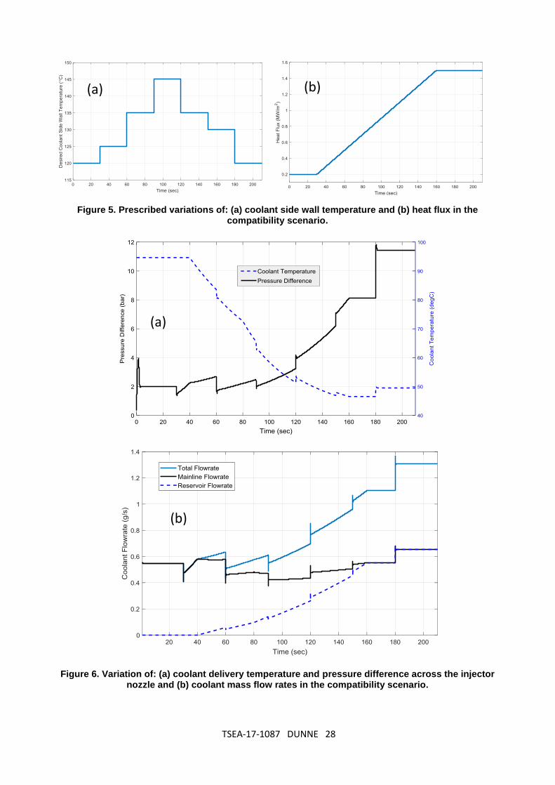
Scenario i): Compatibility Test
The first scenario examines the compatibility of the control system to manage the
temperature at part- and full-load, and also an instantaneous transition between these two
conditions. Figure 5 shows the prescribed variation of coolant-side wall temperature, and
the heat flux over a duration of 210 seconds. As can be seen from figure 5, for t ≤ 30 s, the
heat flux through the wall is constant at 0.2 MW/m2; it then increases linearly to the full-load
conditions of 1.5 MW/m2 at t = 160 s, and remains at this heat flux level for a further 30 s.
The coolant-side wall temperature is varied in seven piece-wise linear steps each of 30 s
duration as follows: i) 120C for 0 ≤ t ≤ 30s; ii) an increase to 125C at t = 30s, then
constant for 30s; iii) an increase to 135C at t = 60s, then constant for 30s; iv) an increase

TSEA-17-1087 DUNNE 17
to 145C at t = 90s, then constant for 30s; v) a decrease to 135C at t = 120s, then constant
for 30s; vi) a decrease to 130C at t = 150s, then constant for 30s; and finally vii) a decrease
to 120C at t = 180s, then constant for 30s. The results of this compatibility simulation are
shown in figures 6 and 7. Figure 6 (a) shows the variation of coolant delivery temperature
and pressure difference across the spray nozzle; figure 6(b) shows the fractional breakdown
of the coolant mass flow, and the total flow. Figure 7 shows both the coolant-side and gas-
side wall temperatures.
Discussion of Scenario i) results
As can be seen from figure 6 the control inputs (i.e. the coolant temperature, coolant flow
rates, and the pressure difference) are all used to achieve the required degree of control.
As would be expected, to accommodate the gradual increase in heat flux, there is an overall
reduction in coolant temperature. This is achieved by injecting water from the low-
temperature reservoir, and from an overall increase in the total coolant mass flow - a
consequence of the change in the pressure difference ∆p. In addition to this overall reduction
in coolant temperature, and the overall increase in mass flow, there are short-term variations
in these parameters that affect control of the coolant-side wall temperature profile as shown
in figure 5. Also shown in figure 5 is that the relatively large value of heat flux of 1.5 MW/m2
is successfully dissipated by spray evaporative cooling using a coolant mass flow rate of 1.4
gm/s, which is very low compared with the use of single-phase liquid-coolant. The benefit of
this very low flow requirement is that the pumping power is significantly lower than for a
conventional engine cooling system. And because pumping power is a parasitic loss, its
reduction translates into a corresponding reduction in fuel consumption and CO2 emissions.
As shown in the insert in figure 7, the control strategy is successful in tracking the
prescribed coolant-side wall temperature without steady-state error. But also within
acceptable response time of less than 2 s. The value of the overshoot in the coolant-side

TSEA-17-1087 DUNNE 18
temperature is within acceptable engineering limits (i.e. ≤ 3C) over the entire duration of
210 seconds. Finally, as shown in figure 7, the gas-side metal temperature remains below
200C over the entire cycle, and this is well within the safe thermal limits for the aluminium
alloys typically used for engine manufacture. This is important for structural integrity since
the gas-side wall temperature must not be allowed to exceed predetermined limits.
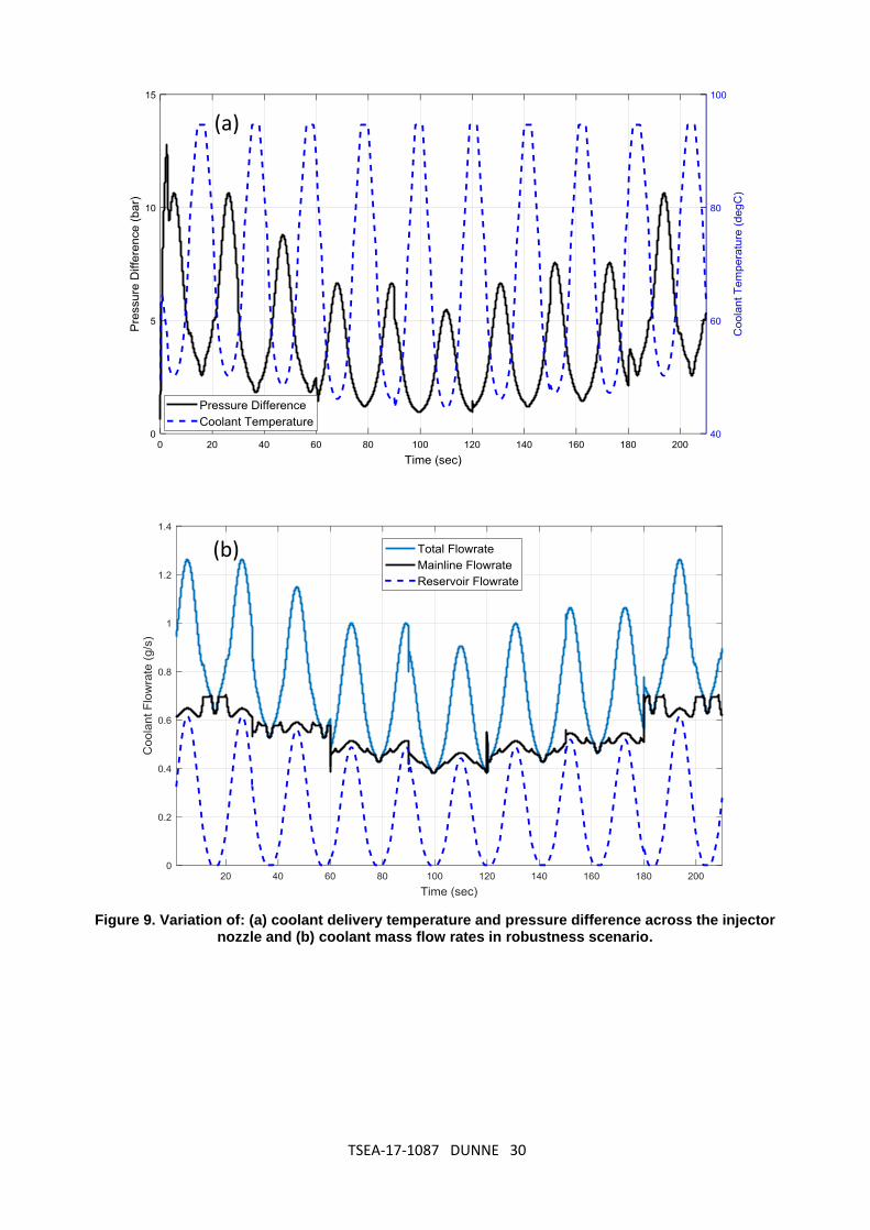
Scenario II: Robustness test
The robustness of the proposed control strategy is now tested in its ability to track the
prescribed coolant side wall temperature shown in figure 5 in the presence of a sinusoidal
variation in the wall heat flux. This variation of heat flux is shown in figure 8, where there are
10 complete heat flux cycles over a duration of 210 second, each having a period of 21
second, with a minimum of 0.25 MW/m2 and a maximum of 1.45 MW/m2. The pressure
difference across the nozzle, and coolant delivery temperature, are treated as control inputs
as shown in figure 9(a). The individual contributions, also the total mass flow rates, are
shown in figure 9(b).
Discussion of Scenario ii) results
Figure 9(b) shows that a pump supplying 12 bar pressure with a flow rate less than 1.5 gm/s,
will allow the controller to manage the thermal behaviour of the system even in the presence
of significant periodic heat flux variations. Figure 9(b) also shows that although there are
changes in the mass flow rate in the main coolant line, most of the control comes from
modulation of the flow from the low-temperature reservoir. This is an important finding as it
clearly demonstrates the need for a low-temperature reservoir and a 3-way valve. Moreover,
the control command (i.e. the pump voltage), is smooth enough to implement in a practical
context to provide the coolant mass flow rate shown in figure 9(b). Smoothness avoids
erratic fluctuations and severe disturbances in the signal that could undermine the controller.
As shown in figure 10, the results of the simulation for this scenario clearly confirm
robustness of the proposed approach. In particular, the temperature tracking control is

TSEA-17-1087 DUNNE 19
achieved with high accuracy and reasonable response time. The fluctuation of temperature
in this scenario is very low, falling within an acceptable operational range i.e. within ±1.5C.
However between 65 seconds and 150 seconds, when the coolant-side wall temperature
exceeds 135C, the gas-side wall temperature does exceed 200C.
Scenario III: An engine test
The final test is to examine the proposed approach for engine cooling in an automotive
vehicle application. This scenario corresponds to a critical situation where the level of heat
flux suddenly jumps from a minimum (part-load) condition to maximum level (full-load). An
example of this scenario is in rapid acceleration of a vehicle from rest. The heat flux profile,
together with the prescribed variation in coolant-side wall temperature, is shown in figure
11. It would appear from this figure that changes in the heat flux and coolant-side wall
temperature have an inverse relation to each other. Closer examination of the scale however
shows that in relation to the 7-fold difference between the maximum and minimum heat flux,
the coolant-side wall temperature is almost constant. An additional requirement is that the
coolant-side wall temperature can, during the sudden increase, respond fully to the desired
change in less than 3 seconds, and in less than 5 seconds, during a sudden decrease of
heat flux.
Discussion of Scenario iii) results
The test results for Scenario iii) in figures 12 and 13, clearly demonstrate the ability of the
proposed control approach to deal with realistic variations in engine load. Figure 12 shows
that both the pressure difference across the nozzle, and the coolant flow rate, are within a
feasible range for practical implementation. In this instance, the pump and nozzle
combination are able to provide 11 bar differential pressure, and 1.6 gm/s of coolant. The
temperatures for the engine test are shown in figure 13. The variation of gas-side wall
temperature remains below 200C, and is considered to be wholly acceptable. Tracking of

TSEA-17-1087 DUNNE 20
the coolant-side wall temperature is also satisfied without unacceptable over- and under-
shoot (i.e. less than 8C). The inserts in figure 11 show that the control, during a sudden
transition of less 3 seconds duration, is able to track the wall temperature from part-load to
full-load, and during a transition of less than 5 seconds, is successfully able to track
temperature during a change from full-load to part-load.
The test results for these three scenarios confirm the potential of spray evaporative cooling
together with the proposed control structure for an automotive engine application. The
proposed cooling system is expected to provide improved engine efficiency. Successful
management of heat flux from the engine block has also been demonstrated, with
significantly lower coolant flow rates using a smaller coolant pump. The control system
design issues to be examined in a realistic implementation are: i) selection of cost-effective
sensors, ii) considerations of power and weight; iii) experimental verification, and iv)
adoption of cooling system anti-erosion standards.
Finally, it is evident that since the simulations assume a rapid response of 4 seconds and
a cool reservoir temperature of 50˚C, rapid response at this reservoir temperature would
not be suitable for operation in very warm climates where the response time would need to
be lengthened (as appropriate for the IC engine in a Hybrid Electric Vehicle).
5. CONCLUSIONS
A new control structure is proposed for the thermal management of road vehicle internal
combustion engines using spray evaporative cooling. The cooling methodology and control
system are shown by simulation to have very good potential in the practical automotive
propulsion application identified. The proposed controller is tested in three different
scenarios to examine compatibility, robustness, and the thermal demands of rapid vehicle
acceleration from rest. The physical model that underpins these simulations is based on a
combination of lumped-parameter modelling, and published correlations associated with

TSEA-17-1087 DUNNE 21
spray evaporative heat transfer. The proposed control methodology and corresponding
control system is shown to track the desired temperature profile with very acceptable
precision and with wholly acceptable transient response performance. A vital design feature
established for the proposed control system is the use of a three-way mixing valve, which
regulates the injected flow of coolant from a separate low temperature reservoir into the
main coolant line. Without this three-way valve and the low temperature reservoir, simulation
results confirm that it would not be possible to achieve the degree of precision control
needed for automotive engine cooling.
Acknowledgements The authors wish to acknowledge funding support for this project from the EPSRC under Contract Number: EP/M005755/1. The technical support is also acknowledged of colleagues at Ford Dunton UK and Dearborn USA, Denso Italy, and the Ricardo Technical Centre Shoreham, UK.

TSEA-17-1087 DUNNE 22
References [1] Incropera, F. P. and DeWitt, D. P., 2002, Fundamentals of heat and mass transfer, John Wiley & Sons, Australia. [2] Gaugler, R.E., 1966, “An Experimental Study of Spray Cooling of High Temperature Surfaces,” PhD thesis, Department of Mechanical Engineering, Carnegie Institute of Technology, Pittsburg, PV. [3] Nukiyama, S., 1966, “Maximum and minimum values of heat Q transmitted from metal to boiling water under atmospheric pressure,” International Journal of Heat and Mass Transfer, 9, (12), pp. 1419-1433. [4] Wachters, L. H. J., and Westerling, N. A. J., 1966, “The Heat Transfer from a Hot Wall to Impinging Water Drops in the Spheroidal State,” Chem. Eng. Sci.,21, pp.1047–1056. [5] Eugene, A., and Mizikar, A., 1970, “Spray cooling investigation for continuous casting of billets and blooms,” Iron Steel Eng. 47 (6) pp. 53–60. [6] Pederson, C. O., 1970, “An Experimental Study of the Dynamic Behavior and Heat Transfer Characteristics of Water Drops Impinging upon a Heated Surface,” International Journal of Heat and Mass Transfer,13, pp. 369–381. [7] Hoogendorn, C. J., and den Hond, R., 1974, “Leidenfrost Temperature and Heat-Transfer Coefficients for Water Sprays Impinging on a Hot Surface,” Proc. 5th Int. Heat Transfer Conf., vol. 4, pp. 135–138. [8] Toda, S., 1972, “A Study of Mist Cooling (First Report: Investigation of Mist Cooling), Heat Transfer: Japanese Research,” 1, pp. 39–50. [9] Toda, S., 1974, “A Study of Mist Cooling (Second Report: Theory of Mist Cooling and Its Fundamental Experiments), Heat Transfer: Japanese Research,” 3, pp. 1–44, [10] Sasaki, K., Sugatani, Y., Kawasaki, M., 1979, “Heat transfer in spray cooling on hot surface,” Tetsu-to-Hagane (J. Iron Steel Inst. Jpn.), 65, pp. 90–96. [11] Monde, M., Kusuda, H., and Uehara, H., “Burnout heat flux in saturated forced convection boiling with two or more impinging jets,” Transactions of the JSME, 46, pp. 1834–1843, 1980. [12] Bolle, L., and Moureau, J. C., 1982, “Spray Cooling of Hot Surfaces,” Multiphase Science and Technology, Hemisphere, Washington, DC. [13] Shoji, M., Wakunaga, T., and Kodama, K., 1984, “Heat Transfer from a Heated Surface to an Impinging Subcooled Droplet (Heat Transfer Characteristics in the Non-wetting Regime),” Trans Jpn. Soc. Mech. Eng., 50(451), pp. 716–722. [14] Yao, S. C., and Choi, K. J., 1987, “Heat Transfer Experiments of Mono-dispersed Vertically Impacting Sprays,” Int. J. Multiphase Flow, 13(5), pp. 639–648. [15] Choi, K. J., and Yao, S. C., 1987, “Mechanisms of Film Boiling Heat Transfer of Normally Impacting Spray, International Journal of Heat and Mass Transfer,” 30(2), pp. 311–318. [16] Katto, Y., and Yokoya, S., 1988, “Critical Heat Flux on a Disk Heater Cooled by a Circular Jet of Saturated Liquid Impinging at the Center”, International Journal of Heat and Mass Transfer, 31(2), pp. 219– 227. [17] Deb, S., and Yao, S.C., 1989, Analysis on film boiling heat transfer of impacting sprays, International Journal of Heat and Mass Transfer, 32(11), pp. 2099–2112,. [18] Mudawar, I. and Valentine, W. S., 1989, Determination of the Local Quench Curve for Spray-Cooled Metallic Surface, Journal of Heat Treatment, 7, pp. 107–121. [19] Pais, M., Tilton, D. Chow, L., and Mahefky, E., 1989, “High heat flux, low superheat evaporative spray cooling,” Proceedings of the 27th AIAA Aerospace Sciences Meeting, Reno, NV. [20] Tilton, D. E., 1989, “Spray cooling”. Ph.D. Dissertation, University of Kentucky. [21] Sehmbey, M.S., Pais, M. R. and Chow, L.C., 1990, “Effect of surface material properties and surface characteristics in evaporative spray cooling,”. AIAA/ASME 5th Joint Thermophysics and Heat Transfer Conference, AIAA 90, 1728, Seattle, WA.
TSEA-17-1087 DUNNE 23
[21] Klinzing, W.P., Rozzi, J.C., and Mudawar, I., 1992, “Film and transition boiling correlations for quenching of hot surfaces with water sprays,” J. Heat Treat, 9(2), pp. 91–103. [22] Tilton, D. E., Tilton, C. L., Moore, C. J., and Ackerman, R. E., 1994, “Spray cooling for the 3-D cube computer. In: Intersociety Conference on Thermal Phenomena in Electronic Systems, Washington, DC, USA. [23] Yao, S.C., and Cox, T.L., 2002, “A general heat transfer correlation for impacting water sprays on high-temperature surfaces,” Exp. Heat Transfer 15(4), pp. 207–219. [24] Nasr, G.G., Sharief, R., James, D.D., and Jeong, J.R., 1999, “Studies of high pressure water sprays from full cone atomizers,” ILASS-Europe’99, Toulouse, pp. 1–6. [25] Yang, J., Chow, L.C., and Pais, M.R., 1996, “Nucleate boiling heat transfer in spray cooling,” Journal of Heat Transfer, 188, pp. 668-671. [26]. Bernardin, J. D., and Mudawar, I., 1997, “Film Boiling Heat Transfer of Droplet Streams and Sprays, Int. J. Heat Mass Transfer,” 40(11), pp. 2579–2593. [27] Hsieh, S-S., Fan, T-C, and Tsai, H-H., 2004, “Spray cooling characteristics of water and R-134a. Part-I: nucleate boiling,” International Journal of Heat and Mass Transfer; 47, pp. 5703-5712. [28] Hsieh, S-S, Fan, T-C., and Tsai, H-H, 2004, Spray cooling characteristics of water and R-134a. Part-II: transient cooling. International Journal of Heat and Mass Transfer; 47, pp. 5713–5724. [29] Estes, K. A., and Mudawar, I., 1995, “Correlation of Sauter mean diameter and critical heat flux for spray cooling of small surfaces,” International Journal of Heat and Mass Transfer, 38, pp. 2985–2996. [30] Mudawar, I., and Estes, K.A., 1996, “Optimizing and predicting CHF in spray cooling of a square surface,” Journal of Heat Transfer, 118, pp. 672–679. [31] Aguilar, G., Majaron, B., Verkruysse, W., Zhou, Y., Nelson J.S., and Lavernia, E.J., 2001, Theoretical and experimental analysis of droplet diameter, temperature, and avaporation rate evolution in cryogenic sprays, International Journal of Heat and Mass Transfer 44(17), pp. 3201-3211. [32] Rini, D.P., Chen, R-H., and Chow, L. C., 2002, “Bubble behavior and nucleate boiling heat transfer in saturated FC-72 spray cooling,” J Heat Transf, 124, pp. 63-72. [33] Di Marzo, M., Tartarini, P., Liao, Y., Evans, D., and Baum, H., 1993, Evaporative cooling due to a gently deposited droplet,” International Journal of Heat and Mass Transfer, 36, pp. 4133–4139. [34] Inada, S., and Yang, W-J., 1994, “Film Boiling Heat Transfer for Saturated Drops Impinging on a Heated Surface,” International Journal of Heat and Mass Transfer, 37(16), pp. 2588–2591. [35] Milke, J. A., Tinker, S. C., and di Marzo, M., 1997, “Effect of dissolved gases on spray evaporative cooling with water,” Fire Technology, 2nd Quarter, 33(2), pp. 99-114. [36] Rybicki, J. R., and Mudawar, I., 2006, “Single-phase and two-phase cooling characteristics of upward-facing and downward-facing sprays,” International Journal of Heat and Mass Transfer, 49(1-2), pp. 5-16. [37] Selvam, R. P. , Lin, L., and Ponnappan, R., 2006, “Direct Simulation of Spray Cooling: Effect of Vapour Bubble Growth and Liquid Droplet Impact on Heat Transfer,” International Journal of Heat and Mass Transfer, 49(23–24) pp. 4265–4278. [38] Visaria, M., and Mudawar, I., 2008, “Effects of high subcooling on two-phase spray cooling and critical heat flux,” IntJ Heat Mass Transf, 51, pp. 5269–5278. [39] Visaria, M., and Mudawar, I., 2008, “Theoretical and experimental study of the effects of spray inclination on two-phase spray cooling and critical heat flux,” International Journal of Heat and Mass Transfer, 51, pp. 2398-2410. [40] Visaria, M., and Mudawar, I., 2009, “Application of two-phase spray cooling for thermal management of electronic devices,” IEEE Trans Compon Packag Technol, 32, pp. 784–793.

TSEA-17-1087 DUNNE 24
[41] Mudawar, I., Bharathan, D., Kelly, K., and Narumanchi, S., 2009, “Two-Phase Spray Cooling of Hybrid Vehicle Electronics,” IEEE Transactions on Components and Packaging Technologies, 32(2). [42] Tilton, D. E., and Tilton, C. L., 2010, “Thermal Management System for Evaporative Spray Cooling,” US Patent US 7,836,706 B2. [43] Cheng, Wen-Long., Zhang, Wei-Wei., Chen, Hua., and Hu, Lei., 2016, “Spray cooling and flash evaporation cooling: The current development and application,” Renewable and Sustainable Energy Reviews, 55, pp. 614–628. [44] Cader, T., Westra, L.J., and Eden, R.C., 2004,”Spray cooling thermal management for increased device reliability,” IEEE Trans Device Mater Reliab, 4, pp. 605–613. [45] Silk, E.A., Golliher, E.L. and Paneer Selvam, R., 2008, Spray cooling heat transfer: Technology overview and assessment of future challenges for micro-gravity application, Energy Convers Manag, 49, pp. 453–468. [46] Anglart, H., Alavyoon, F., and Novarini, R., 2010, Study of spray cooling of a pressure vessel head of a boiling water reactor, Nuclear Eng Des, 240, pp. 252–257. [47] Wagner, J., Marotta, E., and Paradis, I., 2001, “Thermal Modeling of Engine Components for Temperature Prediction and Fluid Flow Regulation,” SAE Tech. Paper 2001-01-1014. [48] Wagner, J., Ghone, M., Dawson, D., and Marotta, E., 2002, “Coolant Flow Control Strategies for Automotive Thermal Management Systems,” SAE Tech. Paper 2002-01-0713. [49] Wagner, J., Srinivasan, V., and Dawson, D., 2003, “Smart Thermostat and Coolant Pump Control for Engine Thermal Management Systems,” SAE Tech. Paper 2003-01-0272. [50] Eberth, J., Wagner, J., Afshar, B., and Foster, R., 2004, “Modeling and Validation of Automotive ‘Smart’ Thermal Management System Architecture,” SAE Tech. Paper 2004-01-0048. [51] Henry, R. , Koo, J., and Richter, C., 2001, “Model Development, Simulation and Validation, of Power Train Cooling System for a Truck Application,” SAE Paper 2001-01-1731,. [52] Setlur, P., Wagner, J., Dawson D., and Marotta, E., 2005, “An advanced engine thermal management system: Nonlinear control and test,” IEEE/ASME Trans. Mechatron., 10(2), pp. 210–220. [53] Page, R., Hnatczuk, W., and Kozierowski, J., 2005, “Thermal Management for the 21st Century—Improved Thermal Control & Fuel Economy in an Army Medium Tactical Vehicle,” SAE Paper 2005-01-2068. [54]. Kim, J., 2007, “Spray Cooling Heat Transfer: The State of the Art”, International Journal of Heat and Fluid Flow, 28(4), pp. 753-767. [55] Ghodbane, M., and Holman, J.P., 1991, “Experimental study of spray cooling with freon-113,” Int. J. Heat Mass Transfer 34, pp. 1163–1174. [56] http://www.bete.com/pdfs/BETE_PJ-metric.pdf (Date accessed: 21st March 2017) [57] Jafari, S., Dunne, J.F., Langari, M., Yang, Z., Pirault, J-P, Long, C. A., and Thalackottore-Jose, J., 2017, “A review of evaporative cooling system concepts for engine thermal management in motor vehicles,” Proceedings of the Institution of Mechanical Engineers, Part D: Journal of Automobile Engineering, 231 (8). pp. 1126-46. [58] Tajjudin, M., Rahiman, M. H. F., Arshad, N. M., and Adnan, R., 2013, “Robust Fractional-Order PI Controller with Ziegler-Nichols Rules,” World Academy of Science, Engineering and Technology International Journal of International Journal of Electrical and Computer Engineering, 7(7), pp. 1034-1041.

TSEA-17-1087 DUNNE 25
FIGURE CAPTIONS
Figure 1. Values of heat transfer coefficient in different cooling techniques, taken from [1]. Figure 2. Schematic diagram of a spray cooling system and relevant parameters. Figure 3. Schematic diagram of the spray cooling control structure. Figure 4. Simulink model for the spray cooling system with associated controller. Figure 5. Prescribed variations of: (a) coolant-side wall temperature and (b) heat flux in the compatibility scenario. Figure 6. Variation of: (a) coolant delivery temperature and pressure difference across the injector nozzle and (b) coolant mass flow rates in the compatibility scenario. Figure 7. Variations with time of the coolant-side and gas-side wall temperatures in the compatibility scenario. Figure 8. Prescribed variation of heat flux with time in the robustness scenario. Figure 9. Variation of: (a) coolant delivery temperature and pressure difference across the injector nozzle and (b) coolant mass flow rates in robustness scenario. Figure 10. Variations with time of the coolant-side and gas-side wall temperatures in the robustness scenario. Figure 11. Prescribed variation with time of the coolant-side wall temperature and heat flux in the engine test scenario. Figure 12. Variations with time of (a) coolant delivery temperature and pressure difference across the injector nozzle and (b) coolant mass flow rates in the engine test scenario. Figure 13. Variations with time of the coolant-side and gas-side wall temperatures in the engine test scenario.

TSEA-17-1087 DUNNE 26
LIST OF FIGURES
Figure 1. Values of heat transfer coefficient in different cooling techniques, taken from [1].
Figure 2. Schematic diagram of a spray cooling system and relevant parameters.
Target surface (w, K, A)
𝑇𝑤,𝑔
D
T𝑐
𝑇𝑤,𝑐
𝐻
𝑃𝑐ℎ𝑎𝑚𝑏𝑒𝑟
{
𝑇𝑤,𝑔: 𝐺𝑎𝑠 𝑠𝑖𝑑𝑒 𝑚𝑒𝑡𝑎𝑙 𝑡𝑒𝑚𝑝𝑒𝑟𝑎𝑡𝑢𝑟𝑒
𝑃𝑐ℎ𝑎𝑚𝑏𝑒𝑟: 𝐶ℎ𝑎𝑚𝑏𝑒𝑟 𝑝𝑟𝑒𝑠𝑠𝑢𝑟𝑒 𝐻 = 𝑁𝑜𝑧𝑧𝑙𝑒 𝑡𝑜 𝑠𝑢𝑟𝑓𝑎𝑐𝑒 𝑑𝑖𝑠𝑡𝑎𝑛𝑐𝑒 𝑤 = 𝑇𝑒𝑠𝑡 𝑝𝑖𝑒𝑐𝑒 𝑡ℎ𝑖𝑐𝑘𝑛𝑒𝑠𝑠 𝑘 = 𝑇𝑒𝑠𝑡 𝑝𝑖𝑒𝑐𝑒 𝑡ℎ𝑒𝑟𝑚𝑎𝑙 𝑐𝑜𝑛𝑑𝑢𝑐𝑡𝑖𝑣𝑖𝑡𝑦 𝐷 = 𝑇𝑒𝑠𝑡 𝑝𝑖𝑒𝑐𝑒 𝑑𝑖𝑎𝑚𝑒𝑡𝑒𝑟
Heat

TSEA-17-1087 DUNNE 27
Figure 3. Schematic diagram of the spray cooling control structure.
Figure 4. Simulink model for the spray cooling system with associated controller.
TSEA-17-1087 DUNNE 28
Figure 5. Prescribed variations of: (a) coolant side wall temperature and (b) heat flux in the compatibility scenario.
Figure 6. Variation of: (a) coolant delivery temperature and pressure difference across the injector nozzle and (b) coolant mass flow rates in the compatibility scenario.
(a)
(b)
(b) (a)

TSEA-17-1087 DUNNE 29
Figure 7. Variations with time of the coolant-side and gas-side wall temperatures in the compatibility scenario.
Figure 8. Prescribed variation of heat flux with time in the robustness scenario.
TSEA-17-1087 DUNNE 30
Figure 9. Variation of: (a) coolant delivery temperature and pressure difference across the injector nozzle and (b) coolant mass flow rates in robustness scenario.
(b)
(a)

TSEA-17-1087 DUNNE 31
Figure 10. Variations with time of the coolant-side and gas-side wall temperatures in the robustness scenario.
Figure 11. Prescribed variation with time of the coolant-side wall temperature and heat flux in the engine test scenario.

TSEA-17-1087 DUNNE 32
Figure 12. Variations with time of (a) coolant delivery temperature and pressure difference across the injector nozzle and (b) coolant mass flow rates in the engine test scenario.
(b)
(a)

TSEA-17-1087 DUNNE 33
Figure 13. Variations with time of the coolant-side and gas-side wall temperatures in the engine test scenario.